IKVM-210-16 - KVM Planet - Free user manual and instructions
Find the device manual for free IKVM-210-16 Planet in PDF.


| Product Type | KVM Switch |
| Model | IKVM-210-16 |
| Number of Ports | 16 |
| Supported Computers | Up to 16 computers |
| Video Resolution | Up to 1920x1440 |
| Console Ports | 1x VGA, 1x PS/2 or USB keyboard/mouse |
| Dimensions (W x D x H) | 440 x 185 x 44 mm (19-inch 1U) |
| Weight | 2.5 kg |
| Power Supply | AC 100-240V, 50/60Hz, external adapter |
| Power Consumption | 12W maximum |
| Control Methods | Front panel buttons, hotkey commands, OSD menu |
| Supported Operating Systems | Windows, Linux, macOS |
| Security | Password protection for OSD access |
| Maintenance | Clean with a dry, soft cloth; avoid liquids |
| Spare Parts / Repairability | No user-serviceable parts; contact support for repairs |
| Package Contents | KVM switch, power adapter, user manual |
Frequently Asked Questions - IKVM-210-16 Planet
User questions about IKVM-210-16 Planet
0 question about this device. Answer the ones you know or ask your own.
Ask a new question about this device
Download the instructions for your KVM in PDF format for free! Find your manual IKVM-210-16 - Planet and take your electronic device back in hand. On this page are published all the documents necessary for the use of your device. IKVM-210-16 by Planet.
USER MANUAL IKVM-210-16 Planet
natural_image
Black PLANNET network interface device with multiple ports and control buttons (no readable text or symbols beyond branding)8-/16-port Combo KVM 8-/16-port Combo IP KVM
IKVM/KVM-210 Series
natural_image
Woman in pink shirt using a computer in an office setting (no visible text or symbols)Copyright
Copyright © 2017 by PLANET Technology Corp. All rights reserved. No part of this publication may be reproduced, transmitted, transcribed, stored in a retrieval system, or translated into any language or computer language, in any form or by any means, electronic, mechanical, magnetic, optical, chemical, manual or otherwise, without the prior written permission of PLANET.
PLANET makes no representations or warranties, either expressed or implied, with respect to the contents hereof and specifically disclaims any warranties, merchantability or fitness for any particular purpose. Any software described in this manual is sold or licensed "as is". Should the programs prove defective following their purchase, the buyer (and not PLANET, its distributor, or its dealer) assumes the entire cost of all necessary servicing, repair, and any incidental or consequential damages resulting from any defect in the software. Further, PLANET reserves the right to revise this publication and to make changes from time to time in the contents hereof without obligation to notify any person of such revision or changes.
All brand and product names mentioned in this manual are trademarks and/or registered trademarks of their respective holders.
Federal Communication Commission Interference Statement
This equipment has been tested and found to comply with the limits for a Class B digital device, pursuant to Part 15 of FCC Rules. These limits are designed to provide reasonable protection against harmful interference in a residential installation. This equipment generates, uses, and can radiate radio frequency energy and, if not installed and used in accordance with the instructions, may cause harmful interference to radio communications. However, there is no guarantee that interference will not occur in a particular installation. If this equipment does cause harmful interference to radio or television reception, which can be determined by turning the equipment off and on, the user is encouraged to try to correct the interference by one or more of the following measures:
- Reorient or relocate the receiving antenna.
- Increase the separation between the equipment and receiver.
- Connect the equipment into an outlet on a circuit different from that to which the receiver is connected.
- Consult the dealer or an experienced radio technician for help.
FCC Caution
To assure continued compliance, use only shielded interface cables when connecting to computer or peripheral devices. Any changes or modifications not expressly approved by the party responsible for compliance could void the user's authority to operate the equipment.
This device complies with Part 15 of the FCC Rules. Operation is subject to the following two conditions:
(1) This device may not cause harmful interference, and (2) this device must accept any interference received, including interference that may cause undesired operation.
Federal Communication Commission (FCC) Radiation Exposure Statement
This equipment complies with FCC radiation exposure set forth for an uncontrolled environment. In order to avoid the possibility of exceeding the FCC radio frequency exposure limits, human proximity to the antenna shall not be less than 20 cm (8 inches) during normal operation.
Safety
This equipment is designed with the utmost care for the safety of those who install and use it. However, special attention must be paid to the dangers of electric shock and static electricity when working with electrical equipment. All guidelines of this and of the computer manufacture must therefore be allowed at all times to ensure the safe use of the equipment.
CE Mark Warning
This is a Class B product. In a domestic environment, this product may cause radio interference, in which case the user may be required to take adequate measures.
WEEE Regulation

To avoid the potential effects on the environment and human health as a result of the presence of hazardous substances in electrical and electronic equipment, end users of electrical and electronic equipment should understand the meaning of the crossed-out wheeled bin symbol. Do not dispose of WEEE as unsorted municipal waste and have to collect such WEEE separately.
Revision
User's Manual of PLANET 8-/16-port Combo KVM
Model: KVM-210-08 / KVM-210-16 / IKVM-210-08 / IKVM-210-16
Rev: 1.00 (January, 2017)
Part No. EM-KVM_IKVM-210 Series_v1.0.doc
Table of Contents
Chapter 1. Product Introduction ....5
1.1 Package Contents....5
1.2 Overview 6
1.3 Features....9
1.4 Specifications ....10
Chapter 2. Hardware Interface ......12
2.1 Physical Descriptions....12
2.2 Hardware Installation ....14
Chapter 3. Operations....17
3.1 Manual Key 17
3.2 Switch Hotkey 17
3.3 OSD (On Screen Display)....18
3.3.1 GOTO 19
3.3.2 SCAN....19
3.3.3 LIST 20
3.3.4 QV (Quick View) 21
3.3.5 EDIT....21
3.3.6 SET 22
Chapter 4. IPKVM Software (For IKVM Series)....24
4.1 System Requirements....24
4.2 IPKVM Software Installation....24
Chapter 5. Web-based Management (For IKVM Series) ......27
5.1 Mouse settings....27
5.2 Network connection....31
5.3 Web Management....32
5.3.1 Console....32
5.3.2 User 34
5.3.3 Log 35
5.3.4 Network....35
5.3.5 System 37
Appendix A: Frequently Asked Questions....38
Chapter 1. Product Introduction
1.1 Package Contents
The package should contain the following:
- Combo KVM Switch x 1
- Quick Guide x 1
IP installation Guide x 1 (For IKVM Series) - KVM Cable x 1
- Rack-mounting Kit x 1
● Power Adapter x 1

If any of the above items are missing, please contact your seller immediately.
1.2 Overview
Easily Control Servers with Flexibility
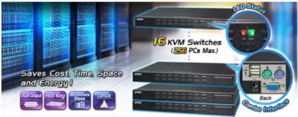
PLANET offers an ideal enterprise 8-/16-port KVM switch solution for company server room or testing facilities. The KVM-210-08/16 features the patented design of the availability of USB and PS/2 interface connection, user-friendly OSD utility and daisy-chain function. The KVM switch solution frees up more table and rack space for users in addition to saving the cost of multiple keyboards, mice and monitors.
Remotely Access your Servers from Anywhere (For IKVM Series)
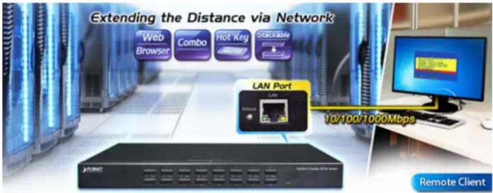
PLANET offers an ideal enterprise 8-/16-port KVM switch solution for company server room or testing facilities. With the innovative IP-based technology, PLANET has turned the traditional KVM switches into true networking devices. The IKVM-210-08/16 captures, digitizes and compresses video signal, and then transmits it with keyboard and mouse signals through IP network. Multiple remote sites can monitor the same PC server simultaneously.
Remote Key Combination (For IKVM Series)
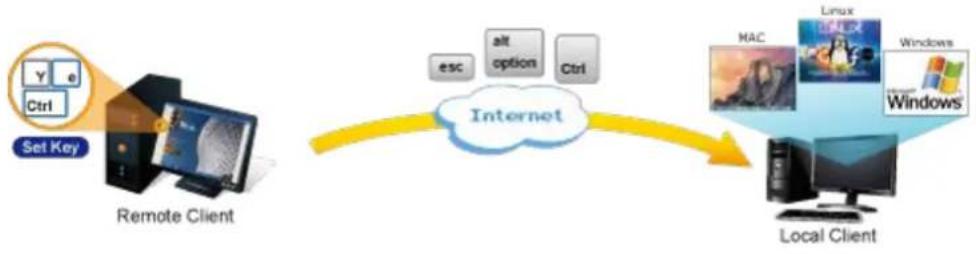
You could set the multiple key combinations at IKVM Series. When you open IKVM software at remote client, you could use these key combinations to control these local PCs with a different OS via the internet.
flowchart
graph LR
    A["Set Key"] --> B["Remote Client"]
    B --> C["Internet"]
    C --> D["Local Client"]
    subgraph Internet
        E["esc"] --> F["alt option"]
        G["Ctrl"] --> H["mac"]
        I["Linux"] --> J["Windows"]
    end
Computer Switching
There are three convenient methods to access any computer connected to the installation:
- Port select button
● Hotkeys on keyboard - OSD (on screen display) at local client and remote client
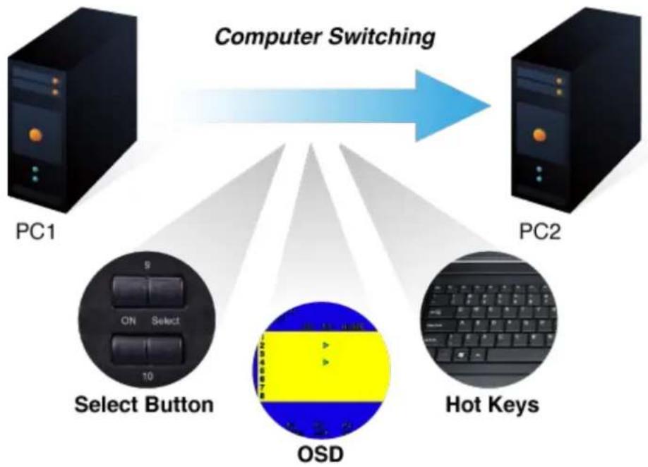
flowchart
graph TD
    A["PC1"] --> B["Select Button"]
    B --> C["OSD"]
    C --> D["Hot Keys"]
    D --> E["PC2"]
    style A fill:#000,stroke:#fff,color:#fff
    style E fill:#000,stroke:#fff,color:#fff
    style B fill:#999,stroke:#333
    style C fill:#ff9,stroke:#333
    style D fill:#999,stroke:#333
    style E fill:#ccc,stroke:#333
Perceptive LED Display
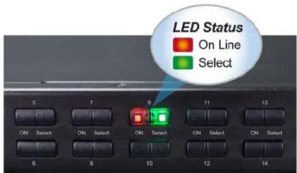
You could check the computer status on the front LED of the IKVM/KVM-210 Series. "Red" indicates that a computer is connected to the corresponding port and "Green" indicates that the computer connected to the corresponding port has focus.
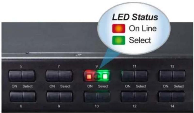
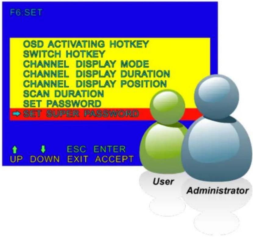
Security Protection
Two level password security only authorizes up to one user and an administrator with a separate profile for each user.
Powerful Mouse/Keyboard Support
In the present computer applications, a mouse has become an indispensable device. The IKVM/KVM-210 Series fully supports all models of PS/2 mice on the market. The KVM also supports the PS/2 keyboard port of code set 1/2/3 and further allows you to use the KVM for all kinds of servers, computers or their combination.
1.3 Features
Hardware
■ 1U rack-mount size and desktop design
■ Standalone machine controls up to 8 sets of computers
■ Up to 2 levels can be cascaded and up to 64 computers can be controlled
■ Front panel status LEDs give a clear indication of the active computers
Security
■ Two-layer password security protection
■ DES, AES and 3DES for data encryption (For IKVM Series)
Management
■ Auto scan mode for monitoring computers
■ Requires no additional software or hardware
■ Computer selection via Port Select Button, Hotkey and On Screen Display (OSD)
■ Hot pluggable: Add or remove computers without having to power down the switch
■ QVS (Quick View Setting): Quickly select your computer by naming or SN number
Remote Access (For IKVM Series)
■ Remotely control PC via TCP/IP and a built-in 10/100/1000Mbps Ethernet port
■ High Video Quality: Resolution up to 2048 x 1536 (local side) or 1920 x 1080 (remote side)
■ Sends the key combinations to a remote computer
■ Administrator and multiple users with password protection
■ Use of the absolute synchronistical technology of mouse to ensure the accuracy of the Windows operating system
■ Expedient bandwidth control
Compatibility
■ Multiplatform support -- Windows, Linux and Sun
■ Multibrowser support (IE, Chrome, Firefox) (For IKVM Series)
■ Supports Microsoft Intellmouse, Logitech Net Mouse and other third-party's PS/2 mice
1.4 Specifications
KVM-210 Series Specifications
| Product | KVM-210-08 | KVM-210-16 | |
| Hardware | |||
| Number of Ports | 8 D-sub ports (15-pin) | 16 D-sub ports (15-pin) | |
| Maximum | 64 by 2-tier star-type cascading (KVM-210-08 x 8) | 256 by 2-tier star-type cascading (KVM-210-16 x 16) | |
| PC Ports | Keyboard | PS/2 female + USB Type A female | |
| Mouse | PS/2 female + USB Type A female | ||
| Video | 8 D-sub ports (15 female) | 16 D-sub ports (15 female) | |
| Console Ports | Keyboard | PS/2 female + USB Type A female | |
| Mouse | PS/2 female + USB Type A female | ||
| Video 1 D-sub port (15 female) | |||
| LED | On Line | 8 (Red) | 16 (Red) |
| Selected | 8 (Green) | 16 (Green) | |
| Button | 1 reset button8 select button | 1 reset button16 select button | |
| Video Resolution | 2048 x 1536 | ||
| Housing | Metal | ||
| Dimensions (W x D x H) | 432 x 155 x 44 mm | ||
| Weight | 2.22kg | ||
| Power Requirement | 9V DC, 1A | ||
| Installation | 1U rack-mountable, desktop | ||
| Management | |||
| PC Selection | Port select buttonHotkeys on keyboardOSD (on screen display) | ||
| Scan Interval | 5~60 seconds | ||
| Security | User password andsuper password | ||
| Environment & Certification | |||
| Operating Temperature | -10 ~ 50 degrees C | ||
| Operating Humidity | 0 ~ 90% | ||
| Regulatory | CE, FCC | ||
IKVM-210 Series Specifications
| Product | IKVM-210-08 | IKVM-210-16 | |
| Hardware | |||
| Number of Ports | 8 D-sub ports (15-pin) | 16 D-sub ports (15-pin) | |
| Maximum Control of PCs | 64 by 2-tier star-type cascading (KVM-210-08 x 8) | 256 by 2-tier star-type cascading (KVM-210-16 x 16) | |
| PC Ports | Keyboard | PS/2 female + USB type A female | |
| Mouse | PS/2 female + USB type A female | ||
| Video | 8 D-sub ports (15 female) | 16 D-sub ports (15 female) | |
| Console Ports | Keyboard | PS/2 female + USB type A female | |
| Mouse | PS/2 female + USB type A female | ||
| Video | 1 D-sub port (15 female) | ||
| LED | On Line | 8 (Red) | 16 (Red) |
| Selected | 8 (Green) | 16 (Green) | |
| Button | 1 reset button8 select buttons | 1 reset button16 select buttons | |
| Remote Console | 1 RJ45 port for 10/100/1000BASE-T | ||
| Video Resolution | Local side: 2048 x 1536 (max)Remote side: 1920 x 1080 (max) | ||
| Housing | Metal | ||
| Dimensions (W x D x H) | 432 x 155 x 44 mm | ||
| Weight | 2.22kg | ||
| Power Requirement | 9V DC, 1A | ||
| Installation | 1U rack-mountable, desktop | ||
| Management | |||
| Supported Protocol | TCP, IP, HTTP | ||
| Client Software | IPKVM Software | ||
| PC Selection | Port select buttonHotkeys on keyboardOSD (on screen display) | ||
| Scan Interval | 5~60 seconds | ||
| Security | User password and super passwordDES, AES and 3DES | ||
| Environment & Certification | |||
| Operating Temperature | -10 ~ 50 degrees C | ||
| Storage Temperature | -20 ~ 60 degrees C | ||
| Operating Humidity | 0 ~ 90% | ||
| Regulatory | CE, FCC | ||
Chapter 2. Hardware Interface
2.1 Physical Descriptions
IKVM/KVM-210 Series Front Panel
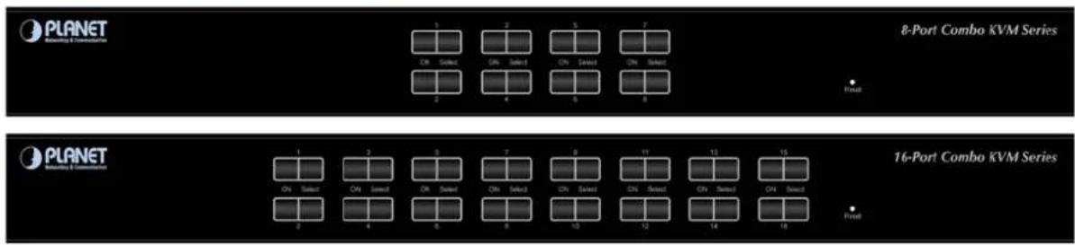
LED and button definitions
| LED Color Function | ||
| On Line | Red | Lights to indicate that the PC is operating. |
| Select | Green | Press this button to select a PC port. |
| Button Function | |
| Reset | This button is hidden in the pinhole. Please hold the reset button for about 5 seconds to load default. |
KVM-210 Series Rear Panels
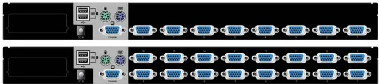
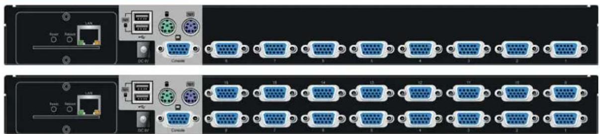
IKVM-210 Series Rear Panels
natural_image
Front and back view of a network device rack with multiple connected ports (no visible text or labels)| Interface Description | ||
| Power Jack | The input power is 9V DC. | |
 | Use the power adapter included in the package; otherwise, it may damage the unit and result in danger. | |
| USB Port Plug | USB keyboard and mouse in this port. | |
| Computer Port | Install the KVM cable connected to a PC here. | |
| Console Ports | ◆ In the Master KVM, connect the monitor, keyboard and mouse here.◆ In the Slave KVM, connect the cable from the Master computer port here. | |
IP Module
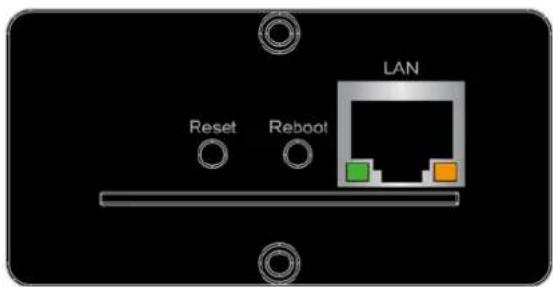
| Interface Description | |
| LAN Port | One 10/100/1000BASE-T RJ45 auto-MDI/MDI-X port. |
| Reboot | Press and release to restart the system. |
| Reset | Press for 5 seconds to reset to default. |
2.2 Hardware Installation
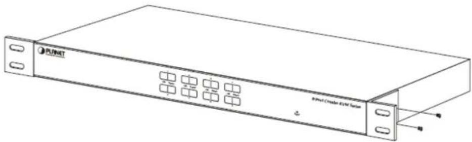
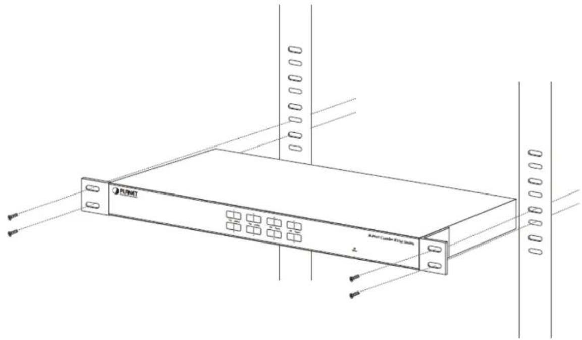
The Switch KVM provides a standard 19-inch rack for the installation of devices. Please use the rack installation accessories attached with the product package. First install the accessories to the device and then the device to the rack.
Step 1. Place your KVM Switch on a hard flat surface, with the front panel positioned towards your front side.
Step 2. Attach a rack-mount bracket to each side of the KVM Switch with supplied screws attached to the package.
natural_image
Line drawing of a PUNET server rack with indicator lights and ports (no text or symbols on the device itself)
Note
1) You must use the screws supplied with the mounting brackets. Damage caused to the parts by using incorrect screws would invalidate your warranty.
2) Please make sure computer and switch KVM are turned off.
Step 3. Secure the brackets tightly.
Step 4. Follow the same steps to attach the second bracket to the opposite side.
Step 5. After the brackets are attached to the Web Smart Switch, use suitable screws to securely attach the brackets to the rack.
natural_image
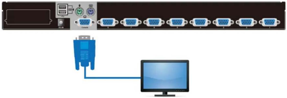
Line drawing of a PUNET server rack with ventilation slots and ports, no text or symbols presentStep 6. Connect the monitor to the KVM Switch. Using the attached cable, or the one included with your monitor, connect it to the HDB-15 female port on the back of the KVM unit labeled with the monitor symbol at the CONSOLE port connector.
natural_image
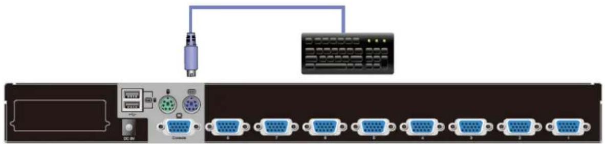
Diagram showing a network device connected to a computer via a blue USB port (no text or symbols present)Step 7. Connect the keyboard to the KVM Switch, via PS/2 or USB interface.
natural_image
Front view of a network device with connected ports and a keyboard (no visible text or symbols)
Note
The console section does not support hot plugging of PS/2 mouse and keyboard.
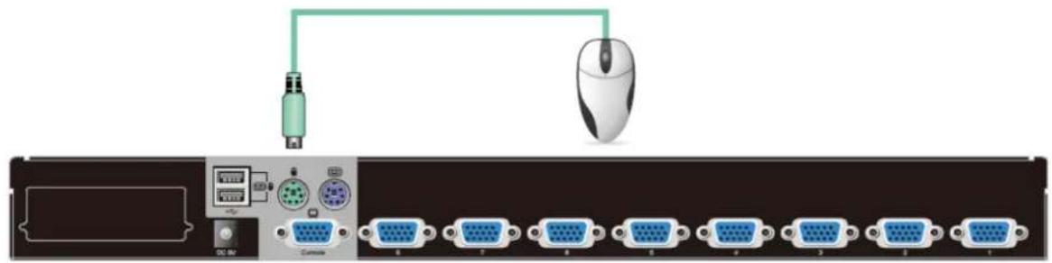
Step 8. Connect the mouse to the KVM Switch, via PS/2 or USB interface.
natural_image
Diagram of a computer setup with connected ports and a mouse, showing no text or symbols on the device itself.
Note
The console section does not support hot plugging of PS/2 mouse and keyboard.
Step 9. Install the Master KVM to the 3-in-1 cable (same as the cable for connecting the KVM to the PC) in the middle of the Slave KVMs.
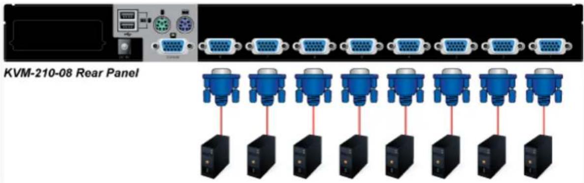
Step 10. Double-check all of the connections. You can check the color of keyboard and mouse connector to make sure the keyboard and mouse cables go to the correct ports.
Step 11. Attach the power supply to the KVM unit and plug the other end into an electrical receptacle. Now you will see the LED for Port 1 light up. Switch on your monitor.

Note
It is not necessary to power down the whole system for installing a new PC or KVM thereafter. All you need is to make sure that the new PC or KVM is OFF during the installation. If the KVM powers down due to external Factors (such as power failure or the power of the KVM is turned off), we recommend you to reinstall the whole system.
Chapter 3. Operations
There are three ways to switch PC. Please see the operation instructions below for more understanding.
3.1 Manual Key
You just need to press the Port Select Button on the front panel of the KVM. The Selection LED (Green) is on, indicating that you are switching to the corresponding port.
3.2 Switch Hotkey
You can use the numeric keys to enter the direct switch. For example, if you want to switch to PC port 2, you could press Ctrl + Ctrl + 2 and switch to PC port 2.
| Scroll + Scroll + Num (Default setting) |
| Ctrl + Ctrl + Num |
| Alt + Alt + Num |
| Shift + Shift + Num |
![SWITCH HOTKEY [SCRLL] + [SCRLL] + [NUM] [CTRL] + [CTRL] + [NUM] [ALT] + [ALT] + [NUM] → [SHIFT] + [SHIFT] + [NUM]](/content/2026/05/940511/images/2af13aec76447a954934ed342cd7b9b9d70aa4a22a700b321b14bb894de29c21.jpg)
3.3 OSD (On Screen Display)
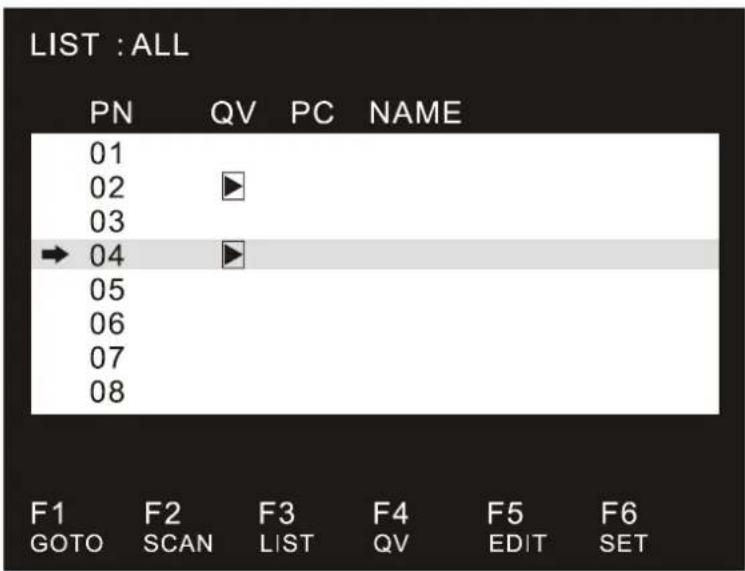
Press the Ctrl on the keyboard twice to start the OSD. Use the key Up, Down and Enter keys on the keyboard to switch or directly move the mouse to the target PC, and then double-click the left button.
| Ctrl + Ctrl (Default setting) |
| Scroll + Scroll |
| Alt + Alt |
| Shift + Shift |
| Parameters Description | |
| PN | This column lists the port numbers for all the CPU ports on the installation. The simplest method to access a particular computer is to move the highlight bar to it, and then press [Enter]. |
| QV | If a port has been selected for Quick View scanning, an arrowhead symbol would display in this column to indicate so. |
| PC | The computers that are powered on and are on-line have an arrowhead symbol in this column to indicate so. |
| NAME | If a port has been given a name, its name would appear in this column. |
3.3.1 GOTO
GOTO allows you to switch directly to a port either by keying in the port's name or its port number.
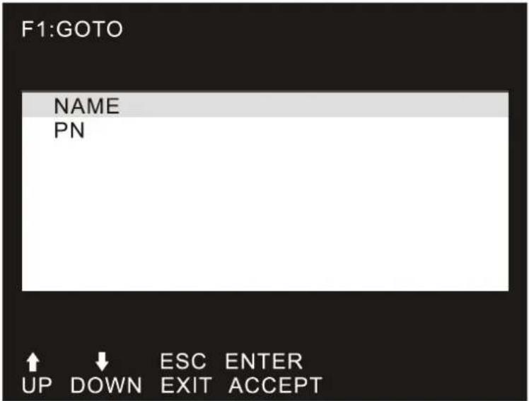
NAME: Move highlight bar to "NAME", press [Enter], input name of a port, and then press [Enter] to confirm.
PN: Move highlight bar to "PN", press [Enter], input port number, and then press [Enter] to switch. If the port number is invalid, it will remind the user to input again.
3.3.2 SCAN
The SCAN function can automatically scan from the currently selected port; the scan interval can be set by users. When scanning, a small window on the screen indicates the current port number. Press [Space] to stop scanning, and the KVM switches to the port last scanned.
3.3.3 LIST
The LIST function lets you broaden or narrow the scope of which port the OSD displays on the main screen.
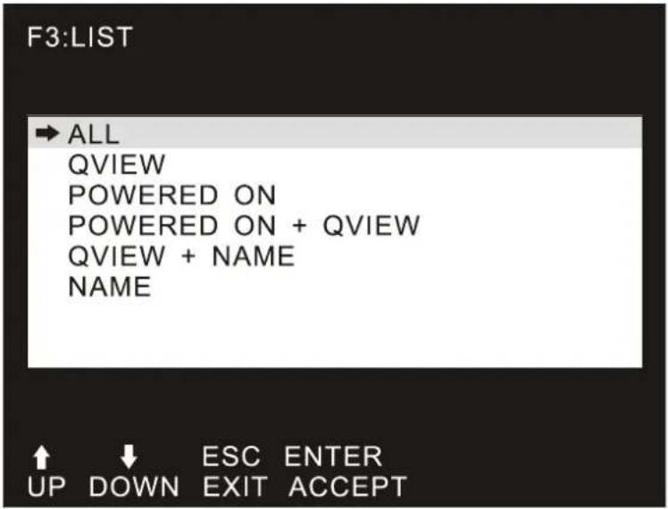
| Parameters Description | |
| ALL | Lists all of the ports on the installation. |
| QVIEW | Lists only the ports that have been selected as Quick View Ports. |
| POWERED ON | Lists only the ports that have their attached computers powered on. |
| POWERED ON + QVIEW | Lists only the ports that have their attached computers powered on and have been selected as Quick View Ports. |
| QVIEW + NAME | Lists only the ports that have been selected as Quick View Ports and have name. |
| NAME | Lists only the ports that have names. |
3.3.4 QV (Quick View)
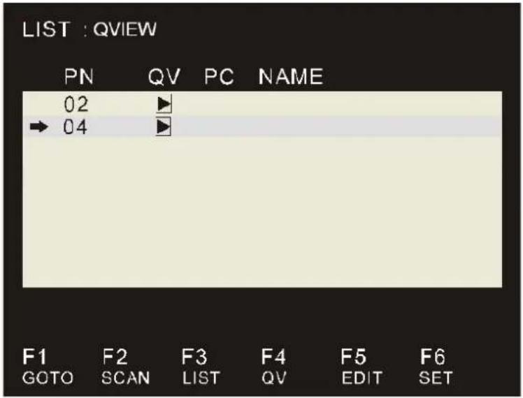
QV function can select port as Quick View. Move the highlight bar to a port, press [F4], an icon of up triangle appears. Press [F4] again, the icon disappears.
3.3.5 EDIT
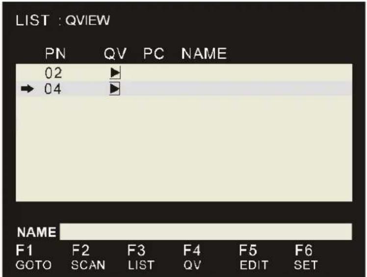
EDIT function creates or edits the name of a port. Press [F5], a pink edit box will appear on the screen. Input name, and then press [Enter], the port is set a name and it will also appear on the screen.
3.3.6 SET
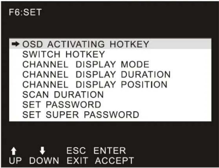
SET function configures the OSD menu. Move the highlight bar to an option, and press [Enter] to enter a setting option.
| Parameters Description | |
| OSD ACTIVATING HOTKEY | Select OSD activating hotkey. |
| SWITCH HOTKEY | Select the switch hotkey to switch PC. |
| CHANNEL DISPLAY MODE | Mode of small tip window. Choices and meanings are below:PN + NAME / PN / NAMEMove the highlight bar to an option and press [Enter] to select it. |
| CHANNEL DISPLAY DURATION | Time the tip window last. Options are following:3 SECOND The tip window lasts for 3seconds.ALWAYS ON The tip window always on the screen.Move the highlight bar to an option and press [Enter] to select it. |
| CHANNEL DISPLAY POSITION | Position of the tip window.A small blue window appears on the screen. Use arrow key to move it, then press [Enter] to specify the position. |
| SCAN DURATION | Duration for scanning one portOptions are 3 seconds, 5 seconds, 10 seconds, 15 seconds, 20 seconds, 30 seconds, 40 seconds, 60 seconds. Move the highlight bar to an option and press [Enter] to select it. |
| SET PASSWORD | Set new password. The password permission is for user.First enter old password, then enter new password and confirm it.The new password is set. If error occurs, the screen will remind users. |
| SET SUPER PASSWORD | Set new password. The password permission is for administrator.First enter old password, then enter new password and confirm it.The new password is set. If error occurs, the screen will remind users. |
| CLEAR THE NAME LIST | Clear the names of port list.You need to enter password to clear the names of port list. |
| RESTORE DEFAULT VALUE | Restore settings to default value.You need to enter password to Restore settings to default value. |
| LOCK CONSOLE | Lock the console.You cannot switch or scan after you lock the console (including switch by pressing the button on the panel or OSD). You need to enter password to set. |
Chapter 4. IPKVM Software (For IKVM Series)
PLANET IKVM Series provides an IPKVM utility to remotely control the server.
4.1 System Requirements
The following are required for further management:
| CPU: | Intel Dual Core 2.0GHz or higher |
| RAM: | 2GB or above recommended |
| Video RAM: | 128MB or above recommended |
| Operating System: | Windows XP / 7 / 10 |
| Video Resolution: | 800 x 600, 1024 x 768, 1280 x 720, 1280 x 800, 1280 x 1024, 1920 x 1080 |
| Browser version | ■ IE10.0 or higher■ Firefox 48.0.2 or higher■ Google Chrome 23.0.1271.97m or higher |

Note
- The video resolution is based on the monitor and display card. Please select Full HD monitor and display card for IKVM Series.
- The maximum video resolution of LCD is 1280 x 1024 with IKVM-210-08M/16M, so remote video solution only supports 1280 x 1024 or lower.
4.2 IPKVM Software Installation
Please refer to the steps below to install the IPKVM software.
Step 1. Insert the bundled CD disk into the CD-ROM drive to launch the autorun program. Once completed, a welcome screen will appear.
Click the "Utility (IPKVM Software)" button and the InstallShield Wizard dialog box will appear as shown below.

Note
If the PC or workstation is not equipped with CD-ROM driver, please download the IKVM software from the PLANET website.
http://www.planet.com.tw/en/support/download.php?view=8184&key=IKVM-210#list
Step 2. Once the Setup program starts running, please click the "Next" button for starting installation.
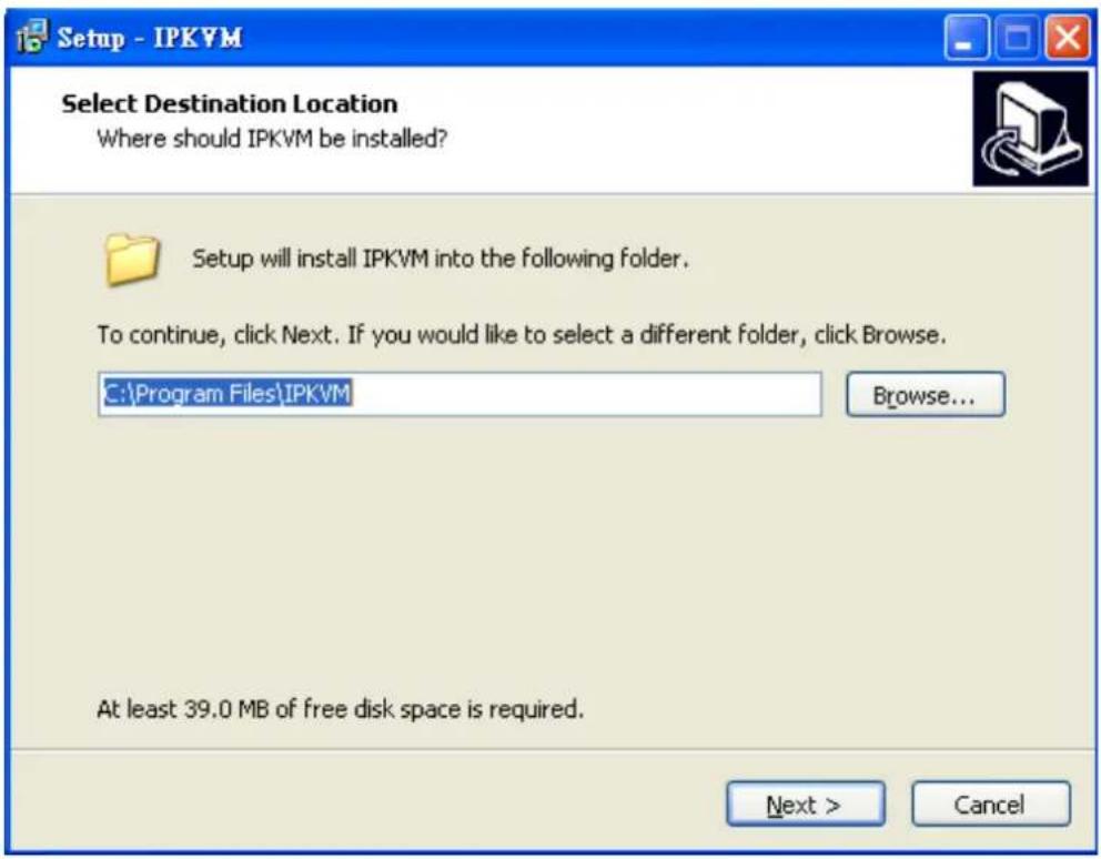
Step 3. Click "Install" for starting installation.
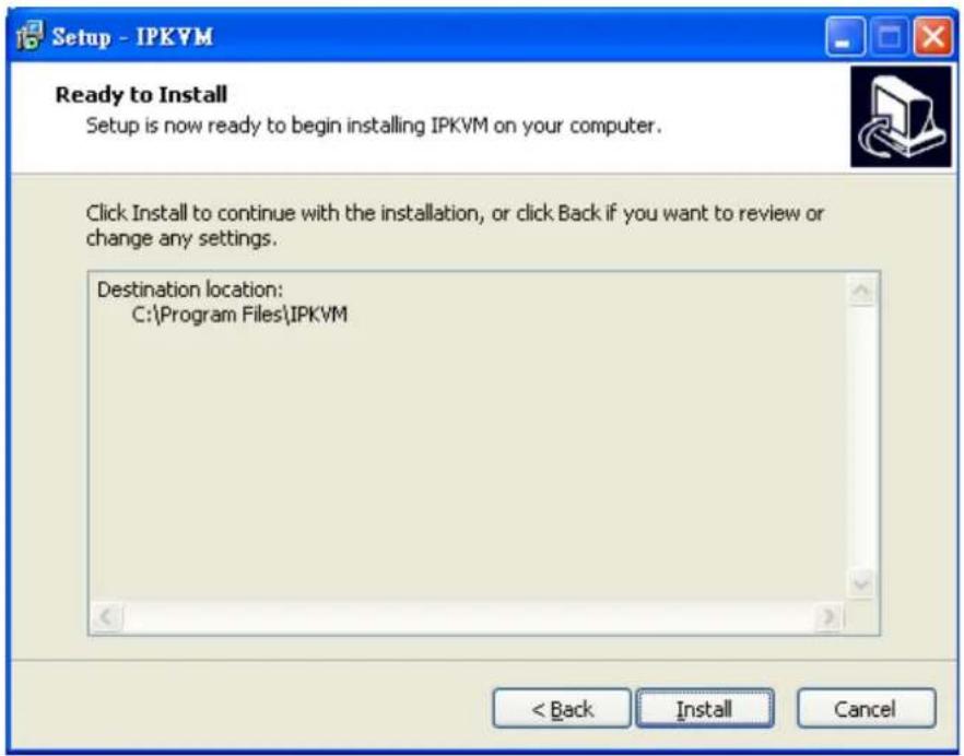
Step 4. Click the "Finish" button for completing the IPKVM Setup.
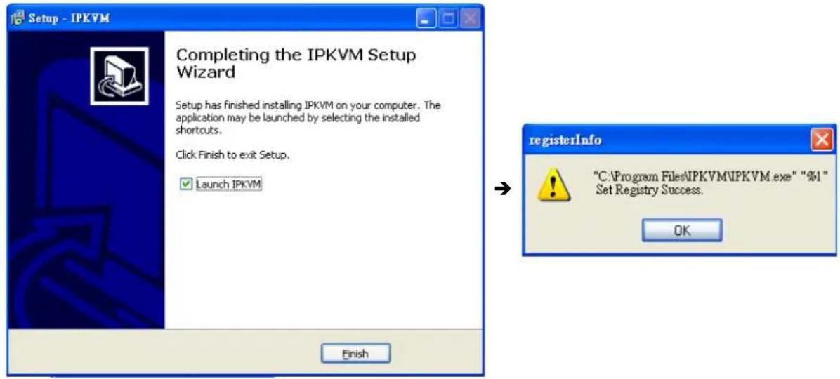

Note
Please do not disable the Launch IPKVM. The IKVM needs registry to initiate the IPKVM software to enable to remotely control PC.
Chapter 5. Web-based Management (For IKVM Series)
This section provides instructions about how to use the web interface to configure and control the PC remotely.
5.1 Mouse settings
A different OS has a different mouse setting. Please refer to the steps below to set the mouse setting of PC before logging to Web.
Windows XP, Windows 2003 and Windows 2008 Settings
To configure KVM target servers running Microsoft Windows XP, Windows 2003 or Windows 2008 operating system:
i. Choose Start > Control Panel > Mouse.
ii. Click the Pointer Options tab.
iii. In the Motion group.
iv. Set the mouse motion speed setting to exactly the middle speed.
v. Disable the "Enhance pointer precision" option.
vi. Disable the Snap To option.
vii. Click OK.
Windows Vista Settings
To configure KVM target servers running Windows Vista operating system:
i. Choose Start > Settings > Control Panel > Mouse.
ii. Select "Advanced system settings" from the left navigation panel. The System Properties dialog opens.
iii. Click the Pointer Options tab.
iv. In the Motion group
v. Set the mouse motion speed setting to exactly the middle speed.
vi. Disable the "Enhanced pointer precision" option.
vii. Click OK.
To configure KVM target servers running Windows 7 operating system:
i. Choose Start > Control Panel > Hardware and Sound > Mouse.
ii. Click the Pointer Options tab.
iii. In the Motion group
iv. Set the mouse motion speed setting to exactly the middle speed.
v. Disable the "Enhanced pointer precision" option.
vi. Click OK.
Windows 2000 Settings
To configure KVM target servers running Microsoft Windows 2000 operating system:
i. Choose Start > Control Panel > Mouse.
ii. Click the Motion tab.
iii. Set the acceleration to None.
iv. Set the mouse motion speed setting to exactly the middle speed.
v. Click OK.
To configure KVM target servers running Linux (graphical user interface):
i. Choose Main Menu > Preferences > Mouse. The Mouse Preferences dialog appears.
ii. Click the Motion tab.
iii. Within the Speed group, set the Acceleration slider to the exact center.
iv. Within the Speed group, set the Sensitivity towards low.
v. Within the Drag & Drop group, set the Threshold towards small.
vi. Close the Mouse Preferences dialog.

Note
If these steps do not work, issue the xset mouse 1 1 command as described in the Linux command line instructions.
To configure KVM target servers running Linux (command line):
i. Set the mouse acceleration to exactly 1 and set the threshold to exactly 1. Enter this command: xset mouse 1 1. This should be set for execution upon login.
To configure Red Hat servers using USB CIMs:
i. Locate the configuration file (usually /etc/modules.conf) in your system.
Using the editor of your choice, make sure that the alias usb-controller line in the modules.conf file is as follows:
alias usb-controller usb-uhci.

Note
If there is another line using usb-uhci in the /etc/modules.conf file, it needs to be removed or commented out
ii. Save the file.
iii. Reboot the system in order for the changes to take effect.
Linux Settings (for Standard Mouse Mode)
To configure KVM target servers running Linux (graphical user interface):
i. Red Hat 5 users, choose Main Menu > Preferences > Mouse, Red Hat 4 users, choose System > Preferences > Mouse. The Mouse Preferences dialog appears.
ii. Click on the Motion tab.
iii. Within the Speed group, set the Acceleration slider to the exact center.
iv. Within the Speed group, set the Sensitivity towards low.
v. Within the Drag & Drop group, set the Threshold towards small.
vi. Close the Mouse Preferences dialog.

Note
-
The settings below are optimized for Standard Mouse mode only.
-
If these steps do not work, issue the xset mouse 11 command as described in the Linux command line instructions.
SUSE Linux 10.1 Settings
To configure the mouse settings:
i. Choose Desktop > Control Center. The Desktop Preferences dialog appears.
ii. Click Mouse. The Mouse Preferences dialog appears.
iii. Open the Motion tab.
iv. Within the Speed group, set the Acceleration slider to the exact center position.
v. Within the Speed group, set the Sensitivity slider to low.
vi. Within the Drag & Drop group, set the Threshold slider to small.
vii. Click Close.

Note
Do not attempt to synchronize the mouse at the SUSE Linux login prompt. You must be connected to the target server to synchronize the mouse cursor.
Sun Solaris Settings
To configure KVM target servers running Sun Solaris:
i. Set the mouse acceleration value to exactly 1 and the threshold to exactly 1. This can be performed from:
The graphical user interface.
To configure the mouse settings (Sun Solaris 10.1):
ii. Choose Launcher. Application Manager - Desktop Controls opens.
iii. Choose Mouse Style Manager. The Style Manager - Mouse dialog appears.
iv. Set the Acceleration slider to 1.0.
v. Set the Threshold slider to 1.0.
vi. Click OK.
IBM AIX 5.3 Settings
Follow these steps to configure KVM target servers running IBM. AIX. 5.3.
To configure the mouse
i. Go to Launcher
ii. Choose Style Manager.
iii. Click Mouse. The Style Manager - Mouse dialog appears.
iv. Use the sliders to set the Mouse acceleration to 1.0 and Threshold to 1.0.
v. Click OK.
5.2 Network connection
Step 1. Connect manager PC to RJ45 LAN port to enable to remotely manage a PC. The default IP address of the IKVM-210 Series is 192.168.0.10, then the manager PC should be set to 192.168.0.x (where x is a number between 1 and 254, except 10), and the default subnet mask is 255.255.255.0.
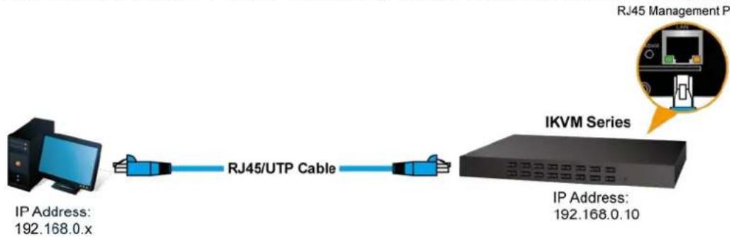
flowchart
graph LR
    A["IP Address: 192.168.0.x"] --> B["RJ45/UTP Cable"]
    B --> C["IKVM Series"]
    C --> D["RJ45 Management P"]
    C --> E["IP Address: 192.168.0.10"]
| Default DHCP Client | N/A |
| Default IP Address | 192.168.0.10 |
| Default Port | 80 |
| Default Login User Name | admin |
| Default Login Password | admin |
| Search Tools | PLANET Smart Discovery Lite |
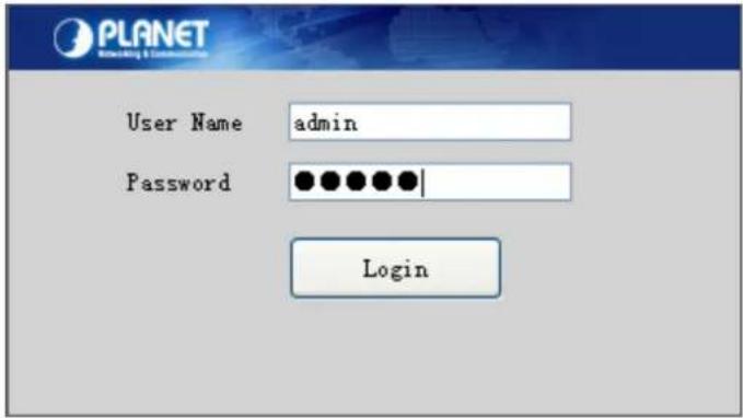
Step 2. Login the Web Management. The username and password are both admin.
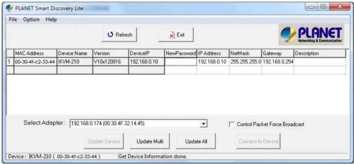
Step 3. If you cannot login the web, please use PLANET Smart Discovery Lite to search IKVM Series.
5.3 Web Management
5.3.1 Console
The Console is the redirected screen, keyboard and mouse of the remote host system that IP-KVM controls.
Online Console
| Modify | PortID | Name | Type | Group | UID | Status | Client |
| 1 | IKVM-210 | usb | C1USB10000000000; | idle |
| Parameters Description | |
| Console | Modify equipment description or register information |
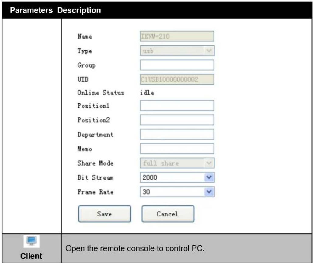
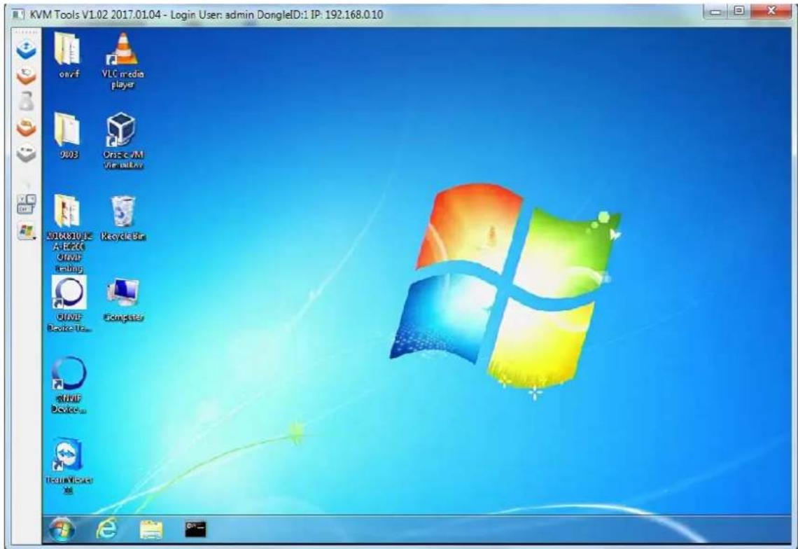
When you click "Client" and link the IPKVM.exe, then open the remote console. Please see the picture below for more understanding.
| Parameters Description | |
 Full Screen Full Screen | Press the Full Screen to make display in full screen. |
 Align Mouse Align Mouse | After login, system will automatically calibrate mouse. If it fails, please click Align Mouse on the left to operate manually. Note A different OS has a different mouse setting. Please refer to the user manual for setting the mouse first. Note A different OS has a different mouse setting. Please refer to the user manual for setting the mouse first. |
 Video Config Video Config | Adjusting display area of screen. |
 Mouse Show Mouse Show | The mouse can appear or hide by clicking it. |
 Set Key Set Key | Remote hot-key edit button -- hot-key operation can be added in the pop-up dialog with the button clicked. |
 Show Key Show Key | Choose the remote shortcut key directly to operate the controlled machine. |
5.3.2 User
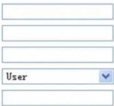
Mainly for user management, which includes three grades: Super Administrator (only one and couldn't be deleted), Administrator and User. User system includes three groups which can be made based on actual using condition. Higher grade user can add, delete or modify lower grade user. It can be done by modifying the tables as shown below.
Group and User
Group
| Level | Group | Query | Modify | |
| super | SuperAdmin | |||
| administrator | Administrat | |||
| normal | User |
| Name | Group | Name2 | Status | Memo | Query | Modify | Delete |
| admin | SuperAdmin | ADMIN | online |
Insert user
Base Parameter
Name
Password
Password Confirm
Group
Memo
Name2
Home Addr
Company Addr
Phone
Memo2
natural_image
Five identical empty rectangular boxes arranged horizontally (no text or symbols)Console Privilege
IKVII-210

Modify
Save
Cancel
| Parameters Description | |
| Super Administrator | With all the permissions of setting operation |
| Administrator | Can edit the Console option setting of authorizationCan add, delete, modify the user rights of the user operation; you can edit the level of user-related settingsCan do the relevant inquiries of Log partCannot do the part of the set operation of Network and System |
| User | Can edit the Console option setting of authorizationCannot do any user rights to add and delete operations; can only do their own user-related settingsCannot do the part of the set operation of Network and System |
5.3.3 Log
Many kinds of log queries and log details are supported as shown below.
Log query

| User Name | Time | Ip | Type | Query |
5.3.4 Network
Some information of server like IP address, UID, name, etc, which can be modified.
Network
Base Parameter
| MAC | 00:50:56:C2:00:06 |
| Name | KMDVM2 |
| Encrypt | 3des |
Network Parameter
| IP | 192.168.0.10 | KeyMouse Port | 5168 |
| Subnet Mask | 255.255.255.0 | Video Port | 6968 |
| Gateway | 192.168.0.254 | WEB port | 80 |
Update
| Parameters Description | |
| MAC | Display the Ethernet MAC address of the device. Note that user cannot change it. |
| Encrypt | DES, AES and 3DES. |
| IP | This address is a unique number that identifies a computer or device on the WAN or LAN. These numbers are usually shown in groups separated by periods, for example, 192.168.0.10. |
| Subnet Mask | Subnets allow network traffic between hosts to be separated based on the network's configuration. In IP networking, traffic takes the form of packets. IP subnets advance network security and performance to some level by organizing hosts into logical groups. Subnet masks contain four bytes and usually appear in the same "dotted decimal" data. For example, a very common subnet mask in its binary demonstration 11111111 11111111 11111111 00000000 will usually be shown in the corresponding, more readable form as 255.255.255.0. |
| Gateway | A gateway is a piece of software or hardware that passes information between networks. You'll see this term most often when you either log in to an Internet site or when you're transient email between different servers. |
| KeyMouse Port | Choose the KeyMouse port. The default value is 5168. |
| Video Port | Choose the Video port. The default value is 6968. |
| Web Port | Choose the Web port. The default value is 80. |
5.3.5 System
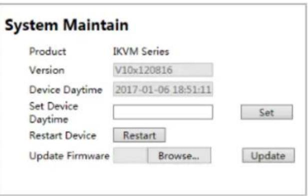
| Parameters Description | |
| Version | This information shows the software version in the device. |
| Device Daytime | Displays the date and time of the device. |
| Set Device Daytime | Click this option to set time and date manually. |
| Restart | The device is restarted without changing any of the settings. |
| Update Firmware | To update the firmware online, click “Browse...” to select the firmware. Then click “Update” to proceed. |
Appendix A: Frequently Asked Questions
Q1. [KVM-210-08/KVM-210-16] What should we do if the keyboard/mouse has no response?
Step 1. Reinstall the keyboard/mouse by unplugging the keyboard/mouse from the control end and then plugging it back.
Step 2. Reboot the PC.
Step 3. In the Auto Scan mode, press [Esc] to exit.
Step 4. If this issue continues, please hold the reset button for about 5 seconds to load default.
Step 5. Try another keyboard/mouse
![Planet IKVM-210-16 - Q1. [KVM-210-08/KVM-210-16] What should we do if the keyboard/mouse has no response? - 1](/content/2026/05/940511/images/5187e2e97cef14dbb5be35e8a9ae88f12c5908c28a8f18b38a02002d3b739424.jpg)
If you are using a special mouse, we recommend you to install the mouse driver provided by the original manufacturer to maximize its functionality.
Q2. [KVM-210-08/KVM-210-16] What should we do if the OSD does not display normally?
Please check the settings below to solve this issue:
1) Check whether the power adapter is the right one or not. The input power is 9V DC,1A.
2) If the setting for the resolution exceeds 2048 x 1536, 350MHz, then set the resolution within the specified range.
3) If the KVM switch is a standalone, then power off the PC. Unplug the special cable of the KVM switch and then power on the KVM switch. Connect the special cable of the KVM switch and power on the PC.
4) If the KVM switch is connected in series, then power off the PC. Unplug the special cable of the KVM switch. Power on the master KVM switch and then start the slave KVM switch. Connect the special cable to the KVM switch and power on the PC.
Q3: [KVM-210-08/KVM-210-16] What should we do if there is a video problem?
Please check the settings below to solve this issue:
5) Check whether or not the setting of the resolution is too high. The maximum video resolution is up to 2048 x 1536, 350MHz.
6) The quality of cable is not good enough. Please use high-quality Smart View cables.
Q4. [KVM-210-08/KVM-210-16] There are foggy images on the external monitor. Why?
The distance between the external console and the KVM-210-08/KVM-210-16 is too long. The maximum VGA cable distance should not exceed 20m and, in some cases, may need to be shorter.
Replace the VGA cable with the one that is appropriately short.
Q5. [IKVM-210-08/IKVM-210-16] Why does the remote console cannot display the screen at Full HD?
Please check the settings below to solve this issue:
1) Please check whether the cable from the switch to the computer is properly connected.
2) IKVM will detect the video resolution of LCD at console port. If the LCD cannot support Full HD that the remote console cannot display, please replace another Full HD LCD.
Q6. [IKVM-210-08/IKVM-210-16] What's the maximum number of users? How many users can be online at the same time?
The maximum is 50 users. Five users can be online at the same time.
- 8-/16-port Combo KVM 8-/16-port Combo IP KVM
- Copyright
- Federal Communication Commission Interference Statement
- FCC Caution
- Federal Communication Commission (FCC) Radiation Exposure Statement
- Safety
- CE Mark Warning
- WEEE Regulation
- Revision
- Table of Contents
- Chapter 1. Product Introduction ....5
- Chapter 2. Hardware Interface ......12
- Chapter 3. Operations....17
- Chapter 4. IPKVM Software (For IKVM Series)....24
- Chapter 5. Web-based Management (For IKVM Series) ......27
- Appendix A: Frequently Asked Questions....38
- Chapter 1. Product Introduction
- Package Contents
- Overview
- Easily Control Servers with Flexibility
- Remotely Access your Servers from Anywhere (For IKVM Series)
- Remote Key Combination (For IKVM Series)
- Computer Switching
- Perceptive LED Display
- Security Protection
- Powerful Mouse/Keyboard Support
- Features
- Hardware
- Security
- Management
- Remote Access (For IKVM Series)
- Compatibility
- Specifications
- Chapter 2. Hardware Interface
- Physical Descriptions
- IP Module
- Hardware Installation
- Chapter 3. Operations
- Manual Key
- Switch Hotkey
- OSD (On Screen Display)
- GOTO
- SCAN
- LIST
- QV (Quick View)
- EDIT
- SET
- Chapter 4. IPKVM Software (For IKVM Series)
- System Requirements
- IPKVM Software Installation
- Chapter 5. Web-based Management (For IKVM Series)
- Mouse settings
- Windows XP, Windows 2003 and Windows 2008 Settings
- Windows Vista Settings
- To configure KVM target servers running Windows 7 operating system:
- Windows 2000 Settings
- To configure KVM target servers running Linux (graphical user interface):
- To configure KVM target servers running Linux (command line):
- To configure Red Hat servers using USB CIMs:
- Linux Settings (for Standard Mouse Mode)
- SUSE Linux 10.1 Settings
- Sun Solaris Settings
- IBM AIX 5.3 Settings
- Network connection
- Web Management
- Console
- User
- Group and User
- Insert user
- Base Parameter
- Console Privilege
- Log
- Network
- Network
- Network Parameter
- System
- Appendix A: Frequently Asked Questions
- Q1. [KVM-210-08/KVM-210-16] What should we do if the keyboard/mouse has no response?
- Q2. [KVM-210-08/KVM-210-16] What should we do if the OSD does not display normally?
- Q3: [KVM-210-08/KVM-210-16] What should we do if there is a video problem?
- Q4. [KVM-210-08/KVM-210-16] There are foggy images on the external monitor. Why?
- Q5. [IKVM-210-08/IKVM-210-16] Why does the remote console cannot display the screen at Full HD?
- Q6. [IKVM-210-08/IKVM-210-16] What's the maximum number of users? How many users can be online at the same time?
Brand : Planet
Model : IKVM-210-16
Category : KVM