
RT-PL-82 - Planer TAURUS - Free user manual and instructions
Find the device manual for free RT-PL-82 TAURUS in PDF.


User questions about RT-PL-82 TAURUS
0 question about this device. Answer the ones you know or ask your own.
Ask a new question about this device
Download the instructions for your Planer in PDF format for free! Find your manual RT-PL-82 - TAURUS and take your electronic device back in hand. On this page are published all the documents necessary for the use of your device. RT-PL-82 by TAURUS.
USER MANUAL RT-PL-82 TAURUS
natural_image
Black and silver electric plow with visible branding (no text or symbols on the device itself)INSTRUCTION MANUAL
MODEL NUMBER RT-PL 82
AFTER SALES SUPPORT TEL: 1300 922 271 EMAIL: service.australia@einhell.com

N26704
1
Electric Planer
What your 3 year warranty means
Great care has gone into the manufacture of this product and it should therefore provide you with years of good service when used properly. In the event of product failure within its intended use over the course of the first 3 year after the date of purchase, we will remedy the problem as quickly as possible once it has been brought to our attention. In the unlikely event of such an occurrence, or if you require any information about the product, please contact us via our after sales support services, details of which can be found in this manual and on the product itself.
Welcome Section
Congratulations on choosing to buy a TAURUS TITANIUM® product.
All products brought to you by TAURUS TITANIUM® are manufactured to the highest standards of performance and safety, and, as part of our philosophy of customer service and satisfaction, are backed by our comprehensive 3 Year Warranty.
We hope you will enjoy using your purchase for many years to come.
Table of Contents
- General Safety Rules Pg. 6
- Layout Pg. 7
- Proper Use Pg. 7
- Technical Data Pg. 7
- Sound and Vibration Pg. 8
- Before Starting the Equipment Pg. 8
- Operation Pg. 9
- Replacing the Power Cable Pg. 9
- Cleaning, Maintenance and Order of Spare Parts Pg. 9
- Disposal and Recycling Pg. 10
3
natural_image
Technical line drawing of a robotic car interior with labeled parts (a and 6), no readable text or symbols beyond labels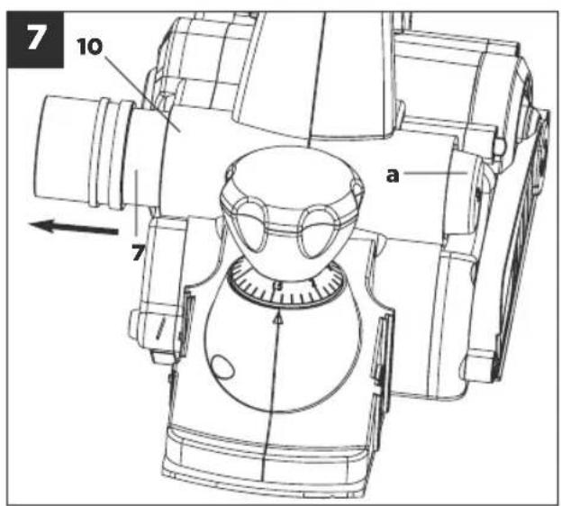
5
flowchart
graph TD
    A["1"] --> B["2"]
    B --> C["3"]
    C --> D["4"]
    D --> E["8"]
    E --> F["5"]
    style A fill:#f9f,stroke:#333
    style B fill:#f9f,stroke:#333
    style C fill:#f9f,stroke:#333
    style D fill:#f9f,stroke:#333
    style E fill:#ccf,stroke:#333
    style F fill:#ccf,stroke:#333
1. GENERAL SAFETY RULES
WARNING! Read all instructions Failure to follow all instructions listed below may result in electric shock, fire and/or serious injury. The term "power tool" in all of the warnings listed below refers to your mains-operated (corded) power tool or battery-operated (cordless) power tool.
SAVE THESE INSTRUCTIONS
1. Work area
a. Keep work area clean and well lit. Cluttered and dark areas invite accidents.
b. Do not operate power tools in explosive atmospheres, such as in the presence of flammable liquids, gases or dust. Power tools create sparks which may ignite the dust or fumes.
c. Keep children and bystanders away while operating a power tool. Distractions can cause you to lose control.
2. Electrical safety
a. Power tools plugs must match the outlet. Never modify the plug in any way. Do not use any adapter plugs with earthed (grounded) power tool. Unmodified plugs and matching outlets will reduce risk of electric shock.
b. Avoid body contact with earthed or grounded surfaces such as pipes, radiators, ranges and refrigerators. There is an increased risk of electric shock if your body is earthed or grounded.
c. Do not expose power tools to rain or wet conditions. Water entering a power tool will increase the risk of electric shock.
d. Do not abuse the cord. Never use the cord for carrying, pulling or unplugging the power tool. Keep cord away from heat, oil, sharp edges or moving parts. Damaged or entangled cords increase the risk of electric shock.
e. When operating a power tool outdoors, use an extension cord suitable for outdoor use. Use of a cord suitable for outdoor use reduces the risk of electric shock.
f. If operating a power tool in a damp location is unavoidable, use a residual current device (RCD) protected supply. Use of an RCD reduces the risk of electric shock.
3. Personal safety
a. Stay alert, watch what you are doing and use common sense when operating a power tool. Do not use a power tool while you are tired or under the influence of drugs, alcohol or medication. A moment of inattention while operating power tools may result in serious personal injury.
b. Use safety equipment. Always wear eye protection. Safety equipment such as dust mask, non-skid safety shoes, hard hat, or hearing protection used for appropriate conditions will reduce personal injuries.
c. Avoid accidental starting. Ensure the switch is in the off-position before plugging in. Carrying power tools with your finger on the switch or plugging in power tools that have the switch on invites accidents.
d. Remove any adjusting key or wrench before turning the power tool on. A wrench or a key left attached to rotating part of the power tool may result in personal injury.
e. Do not overreach. Keep proper footing and balance at all times. This enables better control of the power tool in unexpected situations.
f. Dress properly. Do not wear loose clothing or jewellery. Keep your hair, clothing and gloves away from moving parts. Loose clothes, jewellery or long hair can be caught in moving parts.
g. If devices are provided for the connection of dust extraction and collection facilities, ensure these are connected and properly used. Use of these devices can reduce dust-related hazards.
4. Power tool use and care
a. Do not force the power tool. Use the correct power tool for your application. The correct power tool will do the job better and safer at the rate for which it was designed.
b. Do not use the power tool if the switch does not turn it on and off. Any power tool that cannot be controlled with the switch is dangerous and must be repaired.
c. Disconnect the plug from the power source and/ or the battery pack from the power tool before making any adjustments, changing accessories, or storing power tools. Such preventive safety measures reduce the risk of starting the power tool accidentally.
d. Store idle power tools out of the reach of children and do not allow persons unfamiliar with the power tool or these instructions to operate the power tool. Power tools are dangerous in the hands of untrained users.
e. Maintain power tools. Check for misalignment or binding of moving parts, breakage of parts and any other condition that may affect the power tools operation. If damaged, have the power tool repaired before use. Many accidents are caused by poorly maintained power tools.
f. Keep cutting tools sharp and clean. Properly maintained cutting tools with sharp cutting edges are less likely to bind and are easier to control.
g. Use the power tool, accessories and tool bits etc. in accordance with these instructions and in the manner intended for the particular type of power tool, taking into account the working conditions and the work to be performed. Use of the power tool for operations different from those intended could result in a hazardous situation.
7 5. Service
a. Have your power tool serviced by a qualified repair person using only identical replacement parts. This will ensure that the safety of the power tool is maintained.
6. Recommendation
We recommend that the tool always be supplied via a residual current device with a rated residual current of 30 mA or less.
Planer Safety Warnings
a. Wear ear protectors when planing. Exposure to noise can cause hearing loss.
b. Use auxiliary handle(s), if supplied with the tool. Loss of control can cause personal injury.
c. Hold power tool by insulated gripping surfaces, when performing an operation where the cutting accessory may come in contact with hidden wiring or its own cord. Sanding accessory contacting a "live" wire may make exposed metal parts of the power tool "live" and could give the operator an electrical shock.
Walt for the cutter to stop before setting the tool down. An exposed cutter may engage the surface leading to possible loss of control and serious injury. Do not lose this safety information.

"Caution - Read the operating instructions to reduce the risk of injury."

Wear ear-muffs.
The impact of noise can cause damage to hearing.

Wear a breathing mask.
Dust which is injurious to health can be generated when working on wood and other materials. Never use the device to work on any materials containing asbestos!

Wear safety goggles.
Sparks generated during working or splinters, chips and dust emitted by the device can cause loss of sight.
Important!
When using equipment, a few safety precautions must be observed to avoid injuries and damage. Please read the complete operating manual with due care. Keep this manual in a safe place, so that the information is available at all times. If you give the equipment to any other person, give them these operating instructions as well. We accept no liability for damage or accidents which arise due to non-observance of these instructions and the safety information.
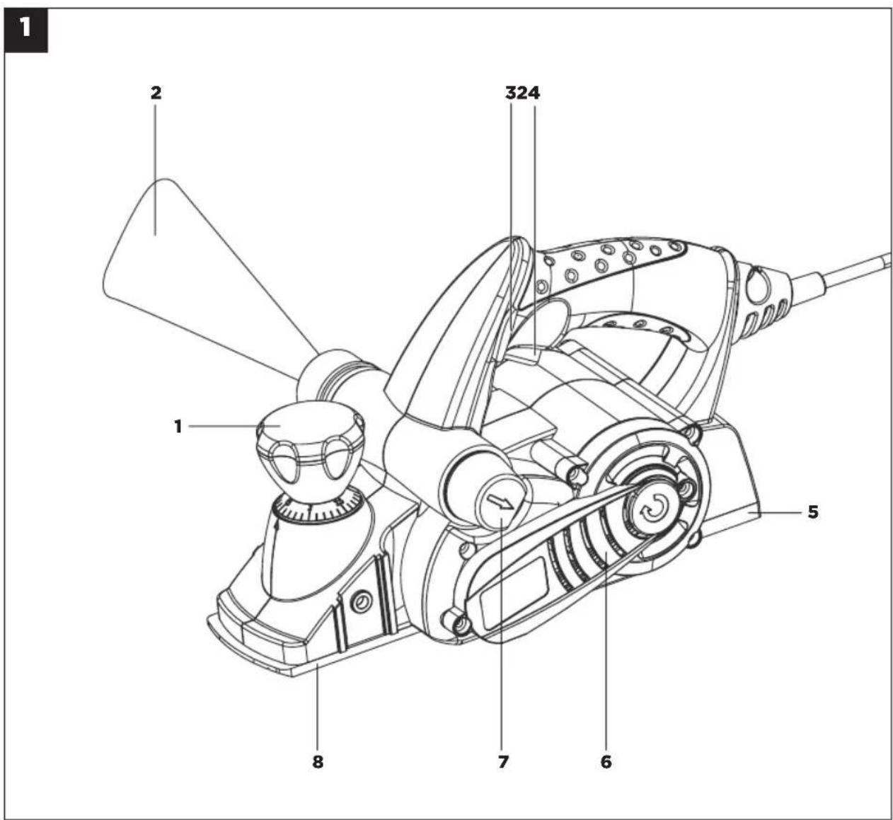
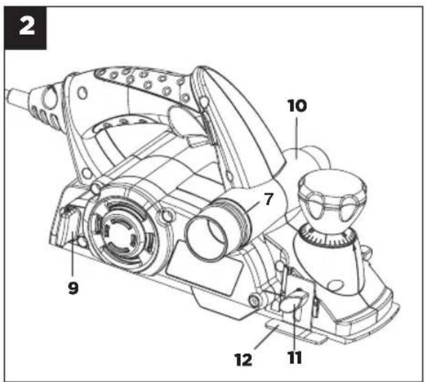
2. Layout
-
Setting knob for the chip depth
-
Dust bag
-
Safety lock-off
-
ON/OFF switch
-
Rear base plate
-
Belt cover
-
Adapter for chip ejector
-
Front base plate
-
Storage compartment for accessories
-
Mount for chip ejector adapter
-
Thumb screw for step depth scale
-
Step depth scale
-
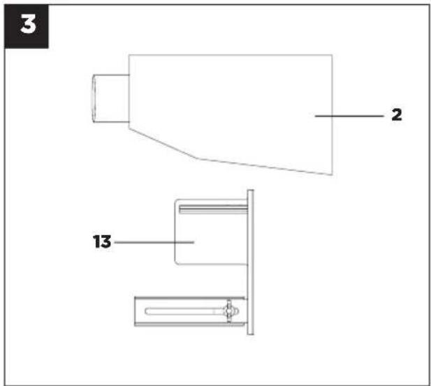
Parallel stop
3. Proper Use
The hand-held electric planer is designed for planing, rabating and chamfering pieces of wood.
The machine is to be used only for its prescribed purpose. Any other use is deemed to be a case of misuse. The user / operator and not the manufacturer will be liable for any damage or injuries of any kind caused as a result of this.
Please note that our equipment has not been designed for use in commercial, trade or industrial applications. Our warranty will be voided if the machine is used in commercial, trade or industrial businesses or for equivalent purposes.
4. Technical Data
Mains voltage: 230 V \~ 50 Hz
Power input: 850 W
Idling speed: 15,000 min -1
Chip depth: 0-3 mm
Rebate depth: 0-18 mm
Plane width: 82 mm
Protection class: II / ☐
Weight: 3.2 kg
5. Sound and Vibration
Sound and vibration values were measured in accordance with EN 60745.
LpA sound pressure level 94 dB(A)
K_pA uncertainty 3 dB
LWA sound power level 105 dB(A)
Kwa uncertainty 3 dB
Wear ear-muffs.
The impact of noise can cause damage to hearing.
Total vibration values (vector sum of three directions)
determined in accordance with EN 60745.
Vibration emission value a_h = 3.61 m/s^2
K uncertainty = 1.5 m/s ^4

IMPORTANT!
The vibration value changes according to the area of application of the electric tool and may exceed the specified value in exceptional circumstances.
Keep the noise emissions and vibrations to a minimum.
- Only use appliances which are in perfect working order.
• Service and clean the appliance regularly. - Adapt your working style to suit the appliance.
- Do not overload the appliance.
- Have the appliance serviced whenever necessary.
- Switch the appliance off when it is not in use.
- Wear protective gloves.
6. Before Starting the Equipment
Before you connect the equipment to the mains supply make sure that the data on the rating plate are identical to the mains data.
Always pull the power plug before making adjustments to the equipment.

IMPORTANT!
For safety reasons, the electric planer must not be operated with the storage compartment for accessories (Fig. 2/Item 9) inserted.
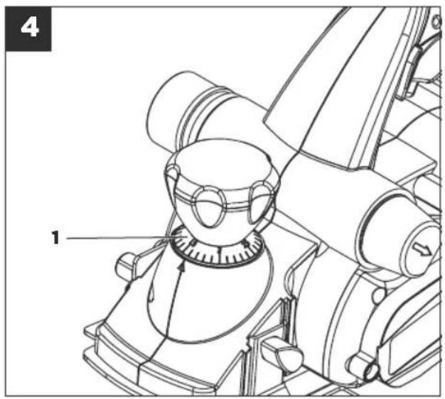
6.1 Adjusting the chip depth (Fig. 4/Item 1)
You can adjust the chip depth in steps of 0.1 mm from 0 to 3 mm by turning the setting knob for the chip depth (1).
Turn the setting knob for the chip depth (1) in a clockwise direction to set a greater chip depth.
Greater chip depth
Turn the setting knob for the chip depth (1) in a counter-clockwise direction to set a lower chip depth.
Lower chip depth
After finishing work, set the chip depth so that the knives are lowered and thus protected from damage. Turn the setting knob for the chip depth to position "0" for this purpose.
6.2 Sawdust extraction (Fig. 5-8)
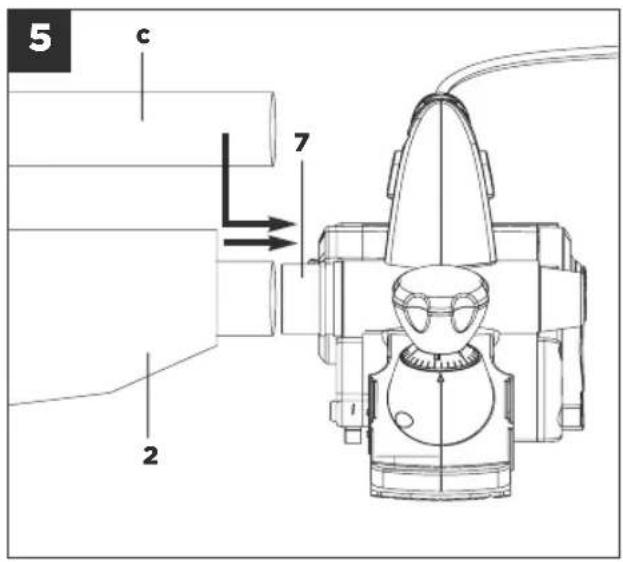
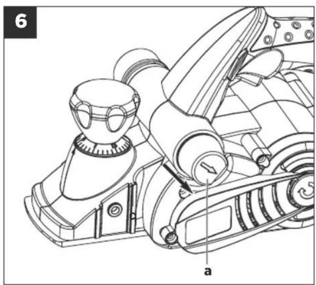
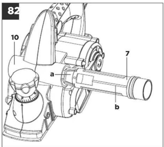
For an optimal sawdust extraction you can connect the supplied dust bag (2) to the hand-held electric plane. To do so, slide the dust bag (2) into the adaptor for the chip ejector (7). The dust bag (2) can be connected optionally on either the left or right. This requires the chip ejector adapter (7) to be fitted accordingly. To remove the chip ejector adapter from the mount, first press the locking knob (a) and then pull the adapter (7) out of the mount (10). Plug the adapter (7) with the required eject direction into the mount (10). As you do so, make sure that the guide (b) of the adapter (7) coincides with the slot of the mount (10). When the locking knob (a) engages correctly it makes an audible click. Check that the adapter is secure. Alternatively you can connect the equipment to a vacuum cleaner. To do so, insert the vacuum cleaner tube (c) into the chip ejector adapter (7). Check that all the parts are properly connected.

IMPORTANT!
The vacuum cleaner you use for the extraction work must be suitable for the workpiece material.
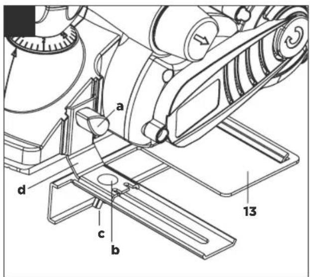
6.3 Parallel stop (Fig. 9/Item 13)
Use the parallel stop (13) when you want to plane parallel to the edge of the workpiece.
Fitting the parallel stop (Fig. 9)
- Fasten the mount (d) of the parallel stop to the left side of the tool using the supplied thumb screw (a).
- Now connect the mount (d) to the slide of the parallel stop (13).
- The guide rail must always be aligned in downward direction.
- Fix the distance required between the parallelstop and the edge of the workpiece.
- Fasten the parts with the carriage bolt (b) and the wing nut (c).
9 7. Operation
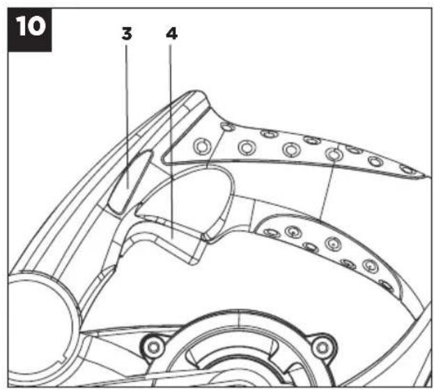
7.1 ON/OFF switch (Fig. 10)
- The hand-held electric planer comes with a safety switch which is designed to prevent accidents.
- To switch on the tool press the safety lockoff (3) and press the ON/OFF switch. (4) The safety lock off (3) can be pressed from the left and right.
- Release the ON/OFF switch (4) to switch off the electric planer. The ON/OFF switch (4) jumps back into its starting position.
7.2 Practical tips
IMPORTANT!
Only ever bring the hand-held electric planer towards the workpiece while switched on.
7.2.1 Planing surfaces
Adjust the desired chip depth. Equip the front base plate and place the hand-held electric plane onto the piece of wood you whish to plane. Then switch on the planer. Push to electric plane over the surface with both hands and make sure that the both the front and the rear base plate lie flat on the workpiece.
Use a low chip depth for finishing surfaces and complete several passes over the surface.
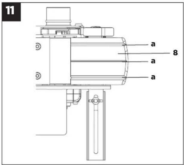
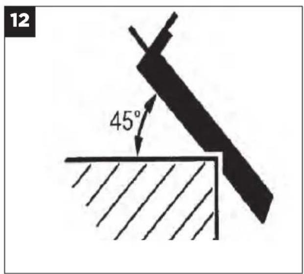
7.2.2 Chamfering edges (Fig. 11-12)
- There are three V-shaped grooves (a) in the front base plate that enable you to plane edges at an angle of 45^ for a smooth finish. You can choose from three different sizes of V-shaped grooves (a).
- Switch on the tool and wait until it reaches full speed. Place the required V-shaped groove (a) on the edge of the workpiece at an angle of 45^ .
- Now move the electric planer along the edge of the workpiece.
- To achieve a good quality result you should keep the feed speed and angle constant.
7.2.3 Planing steps (Fig. 9/13)
- The planing of steps is possible with the help of the parallel stop (13).
- Mount the parallel stop (13) on the left side of the tool (see section 6.3).
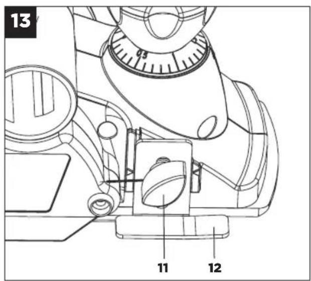
- To mount the depth stop fasten the step depth scale (12) to the front right side of the plane housing with the locking screw (11) (see Fig. 13).
- Release the locking screw (11) and position the step depth scale (12) so that the required step depth is displayed. Tighten the locking screw (11) again.
Width of step:
You can set the width of the step with the parallel stop (13).
Depth of step:
We recommend you to set a cutting depth of 2 mm and to keep planing the workpiece until the required depth of step is reached.
8. Replacing the Power Cable
If the power cable for this equipment is damaged, it must be replaced by the manufacturer or its aftersales service or similarly trained personnel to avoid danger.
9. Cleaning, Maintenance and Ordering of Spare Parts
Always pull out the mains power plug before starting any cleaning work.
9.1 Cleaning
- Keep all safety devices, air vents and the motor housing free of dirt and dust as far as possible.
- Wipe the equipment with a clean cloth or blow it with compressed air at low pressure.
• We recommend that you clean the device immediately each time you have finished using it. - Clean the equipment regularly with a moist cloth and some soft soap. Do not use cleaning agents or solvents; these could attack the plastic parts of the equipment. Ensure that no water can seep into the device.
9.2 Carbon brushes
In case of excessive sparking, have the carbon brushes checked only by a qualified electrician. Important! The carbon brushes should not be replaced by anyone but a qualified electrician.
9.3. Changing the planing knives (Fig. 14-16)
IMPORTANT!
Always pull the plug out of the power socket before doing any work on the equipment.
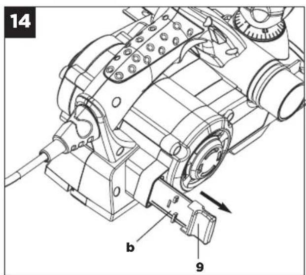
To change the planing knives, use the supplied wrench (a). The wrench (a) is kept in the storage compartment for accessories (9). If required, take the wrench (a) and the planing knife (b) out of the storage compartment for accessories (9) (see Fig. 14).
IMPORTANT!
For safety reasons, the electric planer must not be operated with the storage compartment for accessories (9) inserted.
The hand-held electric planer comes with two carbide metal reversible knives. Reversible knives have two cutting edges and can be reversed. The guide slot on the reversible knives ensures the
same height setting after a change. Replace a worn, blunt or damaged knife.
Carbide metal reversible knives cannot be resharpened.
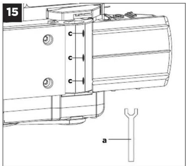
Undo the three hexagonal screws (c) using the wrench (a) supplied and push the carbide metal reversible knife out of the planing shaft using a piece of wood. (see Fig. 15).
Clean the knife seat before fitting. Install the knives in reverse order. Check that the planing knife conforms with both ends of the planing shaft. Always replace both knives to ensure a uniform chip depth.

IMPORTANT!
Before using the hand-held electric planer make sure the knives are installed securely and in the right place.
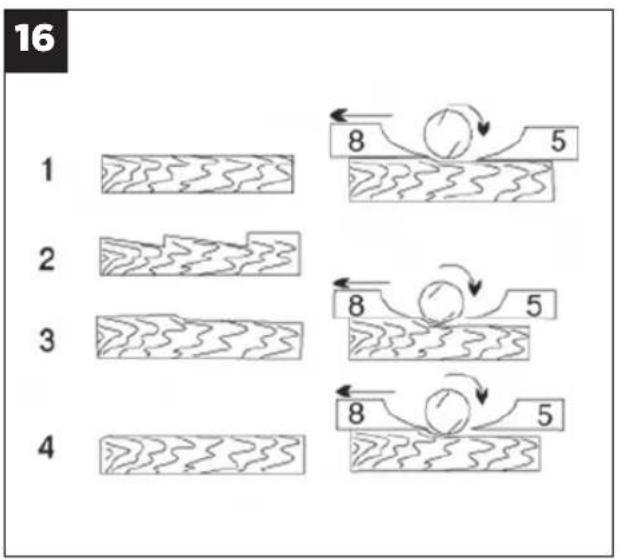
Check the correct setting (Fig. 16)
(8) Front base plate (moving plane shoe)
(5) Rear base plate (fixed plane shoe)
1. Correct adjustment
Result: Smooth planed surfaces
2. Notches in the surface
Problem: The cutting edge on the planing knife (or both planing knives) is not parallel to the height of the rear base plate.
3. Furrows at the start of the planed surface
Problem: The cutting edge on the planing knife (or both planing knives) is below the height of the rear base plate.
4. Furrows at the end of the planed surface
Problem: The cutting edge on the planing knife (or both planing knives) is above the height of the rear base plate.
9.4 Replacing the drive belt (Fig. 17-18)
- The belt should be replaced by a trained expert.
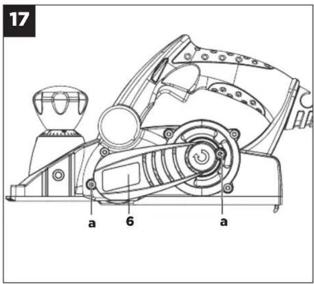
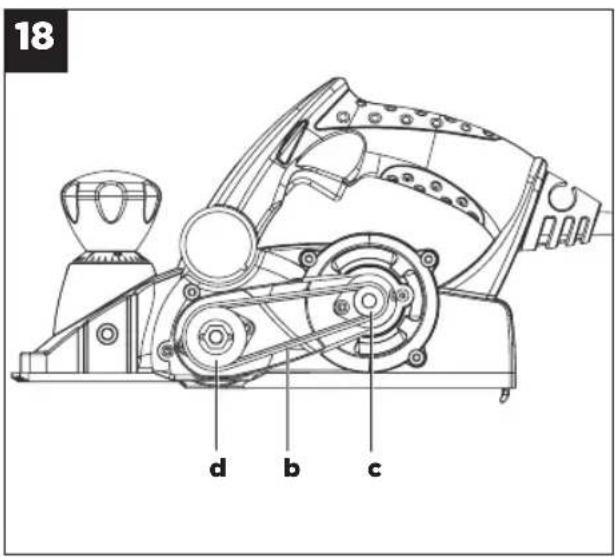
• The drive belt (b) must be replaced if it is worn. - Undo the screws (a) and remove belt cover at the sides (6).
- Remove the worn belt drive (b) and clean the two belt pulleys (c/d). Place the new drive belt on the small belt pulley (c) and pull the belt onto the large belt pulley (d) whilst turning the planing shaft.
- Ensure that the longitudinal grooves on the drive belt are in the guide grooves on the drive wheels.
- Fit the belt cover (6) and secure it with the screws (a).
9.5 Maintenance
There are no parts inside the equipment which require additional maintenance.
9.6 Ordering spare parts
Contact our After Sales Support on 1300 922 271 and quote the following data when ordering spare parts:
- Type of machine
• Article number of the machine
• Identification number of the machine
• Replacement part number of the part required
10. Disposal and Recycling
The unit is supplied in packaging to prevent its being damaged in transit. This packaging is raw material and can therefore be reused or can be returned to the raw material system.
The unit and its accessories are made of various types of material, such as metal and plastic.
Defective components must be disposed of as special waste. Ask your local council.
06/2012
- Electric Planer
- What your 3 year warranty means
- Welcome Section
- Table of Contents
- GENERAL SAFETY RULES
- SAVE THESE INSTRUCTIONS
- Work area
- Electrical safety
- Personal safety
- Power tool use and care
- 5. Service
- Recommendation
- Planer Safety Warnings
- Wear ear-muffs.
- Wear a breathing mask.
- Wear safety goggles.
- Important!
- Layout
- Proper Use
- Technical Data
- Sound and Vibration
- Keep the noise emissions and vibrations to a minimum.
- Before Starting the Equipment
- Adjusting the chip depth (Fig. 4/Item 1)
- Sawdust extraction (Fig. 5-8)
- Parallel stop (Fig. 9/Item 13)
- Fitting the parallel stop (Fig. 9)
- 7. Operation
- ON/OFF switch (Fig. 10)
- Practical tips
- Planing surfaces
- Chamfering edges (Fig. 11-12)
- Planing steps (Fig. 9/13)
- Width of step:
- Depth of step:
- Replacing the Power Cable
- Cleaning, Maintenance and Ordering of Spare Parts
- Cleaning
- Carbon brushes
- Changing the planing knives (Fig. 14-16)
- Check the correct setting (Fig. 16)
- Correct adjustment
- Notches in the surface
- Furrows at the start of the planed surface
- Furrows at the end of the planed surface
- Replacing the drive belt (Fig. 17-18)
- Maintenance
- Ordering spare parts
- Disposal and Recycling
Brand : TAURUS
Model : RT-PL-82
Category : Planer