AC-MX1616-AUHD-GEN2 - Router AVPro Edge - Free user manual and instructions
Find the device manual for free AC-MX1616-AUHD-GEN2 AVPro Edge in PDF.


| Type of Product | 16x16 HDMI 2.0 Matrix Router (4K UHD) |
| Model | AC-MX1616-AUHD-GEN2 |
| Brand | AVPro Edge |
| Dimensions (W x D x H) | 17.2 x 8.3 x 1.7 inches (rackmount, 1U) |
| Weight | Approx. 8 lbs (3.6 kg) |
| Power Supply | 100-240V AC, 50/60Hz, internal |
| Video Inputs | 16 x HDMI Type A (4K@60Hz 4:4:4, HDR10, Dolby Vision) |
| Video Outputs | 16 x HDMI Type A (same as inputs) |
| Supported Resolutions | Up to 4K@60Hz 4:4:4 8-bit, 4K@60Hz 4:2:0 10-bit, 1080p@120Hz |
| HDCP Support | HDCP 2.2 and 1.4 compliant |
| Audio Support | Up to 7.1 LPCM, Dolby Digital, DTS 5.1, bitstream pass-through |
| Control Interfaces | Front panel buttons, IR remote, RS-232, TCP/IP (Web GUI) |
| EDID Management | Internal EDID library and pass-through |
| Scaling / Switching | No scaling (seamless switching, zero frame delay) |
| Rackmount | 1U height, rack ears included |
| Cooling | Internal fan, side venting |
| Operating Temperature | 32°F to 104°F (0°C to 40°C) |
| Cleaning & Maintenance | Wipe exterior with dry microfiber cloth; do not use liquids or solvents |
| Safety Precautions | Do not expose to moisture; ensure proper ventilation; unplug before cleaning |
| Spare Parts & Repairability | Replaceable power supply unit, rack ears; contact AVPro Edge for service |
| General Information | Professional-grade 16x16 HDMI matrix for AV distribution, supports KVM extension |
Frequently Asked Questions - AC-MX1616-AUHD-GEN2 AVPro Edge
User questions about AC-MX1616-AUHD-GEN2 AVPro Edge
0 question about this device. Answer the ones you know or ask your own.
Ask a new question about this device
Download the instructions for your Router in PDF format for free! Find your manual AC-MX1616-AUHD-GEN2 - AVPro Edge and take your electronic device back in hand. On this page are published all the documents necessary for the use of your device. AC-MX1616-AUHD-GEN2 by AVPro Edge.
USER MANUAL AC-MX1616-AUHD-GEN2 AVPro Edge
The AC-MX1616-AUHD-GEN2 is a true high bandwidth powerhouse. Supporting the full HDMI 2.0a/b specification and supporting every flavor of HDR, this matrix will ensure you can get the most out of any system. This unit supports uncompressed HDR formats Including HDR, HDR10, HDR10+, Dolby Vision, HLG, BBC and NHK. All of them are supported in up to 4K 60Hz and up to 12 Bit Deep Color. All color space compression is compatible.
Our unique design has allowed us to improve high bandwidth switching speeds. Average speeds of less than 3 seconds – this is an industry best for this advanced level of actual uncompressed, high bandwidth w/ HDR switching. Maximum compatibility and speed improve the customer experience immensely.
The sleek, low-profile and high-density design make for a sleek machine that saves you valuable space in the rack room. This combined with a OLED setup screen on the front that makes setup and management a breeze will make this a staple in your large demanding installations!
Features:
- HDMI 2.0(a/b)
• 18Gbps Bandwidth Support
• 4K60 4:4:4 Support
• Ultimate HDR Support (HDR 10 & 12 Bit)
• Dolby Vision, HDR10+ and HLG Support
• HDCP 2.2 (and all earlier versions supported) - Simple setup with front panel control screen
- WebOS for simple connectivity and control/management
• Ultra-Low Profile (1U)
- Fast Switching
• Advanced EDID Management
• IR, RS-232 and LAN Control Options
• Digital Coax Audio Out (6CH PCM, DD, DTS)
- Driver Support for Crestron, C4, RTI, ELAN and more!!!
- Extracted Audio Now Has 3 Operating Modes. Bound to Input, Bound to Output, or Independent Matrix
Easy to use:
- Feature rich
- Fast Switching
- Setup screen
- IR Remote
• IR & RS-232 Control
• LAN Control
In The Box:
• AC-MX1616-AUHD-GEN2 Matrix
- IR Remote Control
- IR Extension Cable
• 12V/5A Power Supply
- Mounting Brackets
- 5 pin terminal connectors for extracted Audio
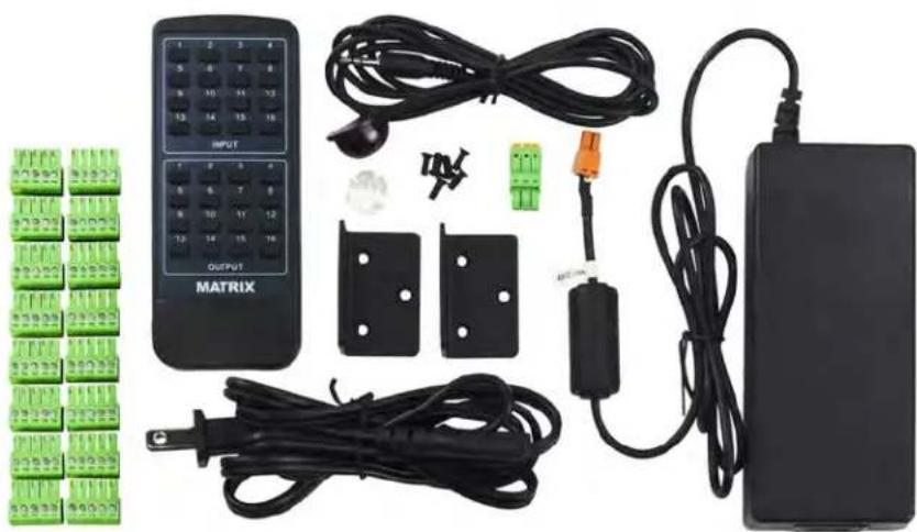
natural_image
Electrical circuit components including a multi-connector keypad, connector blocks, and power adapter (no visible text or symbols)| VIDEO: | |
| VIDEO RESOLUTIONS | UP TO 4K 60HZ 4:4:4 |
| VESA RESOLUTIONS | UP TO DCI 4K (4096X2160) |
| HDR FORMATS/RESOLUTIONS | 420, 422, 444 (10 AND 12 DEEP COLOR)HDR10, HDR10+, DOLBY VISION (24/30 FRAMES), HLG |
| COLOR SPACE | YUV (COMPONENT), RGB(CSC: REC. 601, REC. 709, BT2020, DCI, P3 D6500) |
| CHROMA SUBSAMPLING | 4:4:4, 4:2:2, 4:2:0 SUPPORTED |
| DEEP COLOR | UP TO 16 BIT (1080), UP TO 12 BIT (4K) |
| AUDIO: | |
| AUDIO FORMATS SUPPORTED HDMI | PCM 2.0 CH, LPCM 5.1 & 7.1, DOLBY DIGITAL, DTS 5.1, DOLBY DIGITAL PLUS, DOLBY TRUEHD, DTS-HD MASTER AUDIO, DTS-X, DOLBY ATMOS |
| AUDIO FORMATS SUPPORTED EXTRACTED (COAX) | PCM 2 CH, LPCM 6 CH, LPCM 7 CH, DOLBY DIGITAL, DOLBY DIGITAL PLUS, DTS-HD MASTER AUDIO |
| AUDIO EXTRACTION LOCATION | BIND TO INPUT, BIND TO OUTPUTOR MATRIX (INDEPENDENT) |
| DISTANCE: | |
| HDMI IN/OUT (4K60 4:4:4) | UP TO 50 FEET (USING BULLET TRAIN HDMI) |
| HDMI IN/OUT (W/ AOC CABLE) (4K60 4:4:4) | UP TO 130 FEET (USING BULLET TRAIN AOC) |
| OTHER: | |
| BANDWIDTH | 18 GBPS |
| HDCP | HDCP 2.2 AND EARLIER |
| CONTROL: | |
| PORTS | LAN, RS232, IR, MICR USB |
| DRIVERS | C4, RTI, ELAN, CRESTRON, URC (FOR MORE - SEE DRIVERS PAGE) |
| PC SOFTWARE | YES |
| LAN WEBOS | YES |
| PORTS: | |
| HDMI | TYPE A |
| LAN | RJ45 W/ WEB INTERFACE/CONTROL |
| AUDIO (EXTRACTED DIGITAL) | 5 PIN TERMINAL BLOCK |
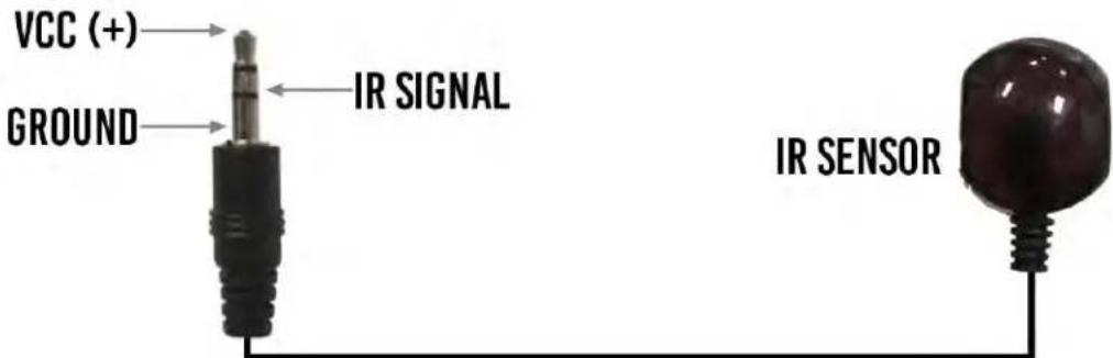
| IR RX | 3.5MM STEREO (3 CONDUCTOR) |
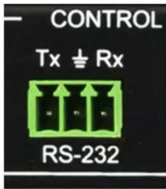
| RS232 | 3 PIN TERMINAL BLOCK |
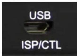
| USB | MICRO - FOR UART COMMUNICATION/CONTROL |
| ENVIRONMENTAL: | |
| OPERATING TEMPERATURE | 23 TO 125°F (-5 TO 51°C) |
| STORAGE TEMPERATURE | -4 TO 140°F (-20 TO 60°C) |
| HUMIDITY RANGE | 5-90% RH (NO CONDENSATION) |
| POWER: | |
| POWER CONSUMPTION (TOTAL) | 92 WATTS MAX |
| POWER SUPPLY - MATRIX | INPUT: AC 100-240V ~ 50/60HZOUTPUT: DC 48V 3A |
| DIMENSIONS: | |
| DIMENSIONS (UNIT ONLY HEIGHT/DEPTH/WIDTH) | MM: 50.8 X 260.35 X 441.33INCH: 2 X 10.25 X 17.375 |
| DIMENSIONS (PACKAGED HEIGHT/DEPTH/WIDTH) | MM: 88.9 X 444.5 X 495.3INCH: 3.5 X 17.5 X 19.5 |
| RACK UNITS | 1 UNIT |
| WEIGHT (UNIT) | 11 LBS /5 KG |
| WEIGHT (PACKAGED) | 15 LBS/7 KG |
| *SPECIFICATIONS SUBJECT TO CHANGE WITHOUT NOTICE. MASS & DIMENSIONS ARE APPROXIMATE | |
Table of Contents
Introduction, Features, In the Box 2
Specifications 3
Device Overview 5
Front Panel Control 6
Navigating the Control Screen 7
Control Screen - EDID Management 8
Control Screen - Audio Settings 9
Control Screen - Network Settings 10
IR Details 11
RS-232 and TCP/IP Commands.... 12
Setting DCHP Command Example.... 13
Command List.... 14-15
Using Multiple Units in One System...... 16
Extracted Audio.... 17-18
PC Control Software - Side Bar.... 19
PC Control Software - Matrix Tab.... 20-21
PC Control Software - EDID Tab.... 22
PC Control Software - IP Config Tab.... 23
Web Interface - Sense Switch.... 24
Web Interface - Audio Matrix.... 25
Web Interface - EDID Manage.... 26
Web Interface - System Config.... 27
Common Usage Diagram.... 28
Maintenance & Support.... 29
Warranty.... 30
Device Feature Overview:
Uncompressed \~ Uncompressed base-band video means that what you put in it what comes out. This allows the integrator ultimate control to use any infrastructure they want. Use pure fiber like Cleerline, Bullet Train Cables (Long Haul, Shout Haul), or 18Gbps HDBaseT Extenders (AC-EX40-444) to get the full bandwidth and full picture!
Ultimate HDR Support \~ This matrix supports all flavors of HDR in all formats. Including HDR, HDR10, HDR10+, Dolby Vision, HLG, BBC and NHK. All of them are supported in up to 4K 60Hz and up to 12 Bit Deep Color. All color space compression are compatible.
Extreme EDID Management \~ With 29 on board EDID's, including HDR EDID's, not getting a picture is simply a thing of the past. You can manage the input side of the switch by selecting a preloaded EDID. It also has the ability to INSTANTLY read an EDID from any connected display and apply it to the desired input, all with the push of a button. Goodbye EDID problems...
Front Panel Screen \~ Make setup a breeze! The front panel allows you to do basic setup including; EDID, Audio, Matrixing and network. All without connecting a PC or hooking anything up. This additional mode of control is a welcome resource on the job site.
WebOS\~ Full matrix control is available on the internal WebOS - Simply plug the matrix into the network and punch in the default IP (192.168.1.239) or use DHCP to connect to a full control system! The WebOS is designed with mobile devices in mind, so feel free to use you phone or tablet for real-time control.
Fast Switching \~ Our unique design has allowed us to improve high bandwidth switching speeds. Average speeds of less than 3 seconds – this is an industry best for this advanced level of actual uncompressed, high bandwidth w/ HDR switching.
Audio De-Embedding \~ Our unique Audio De-Embedding allows 3 modes - Bind to Input, Bind to Output, or Matrix.
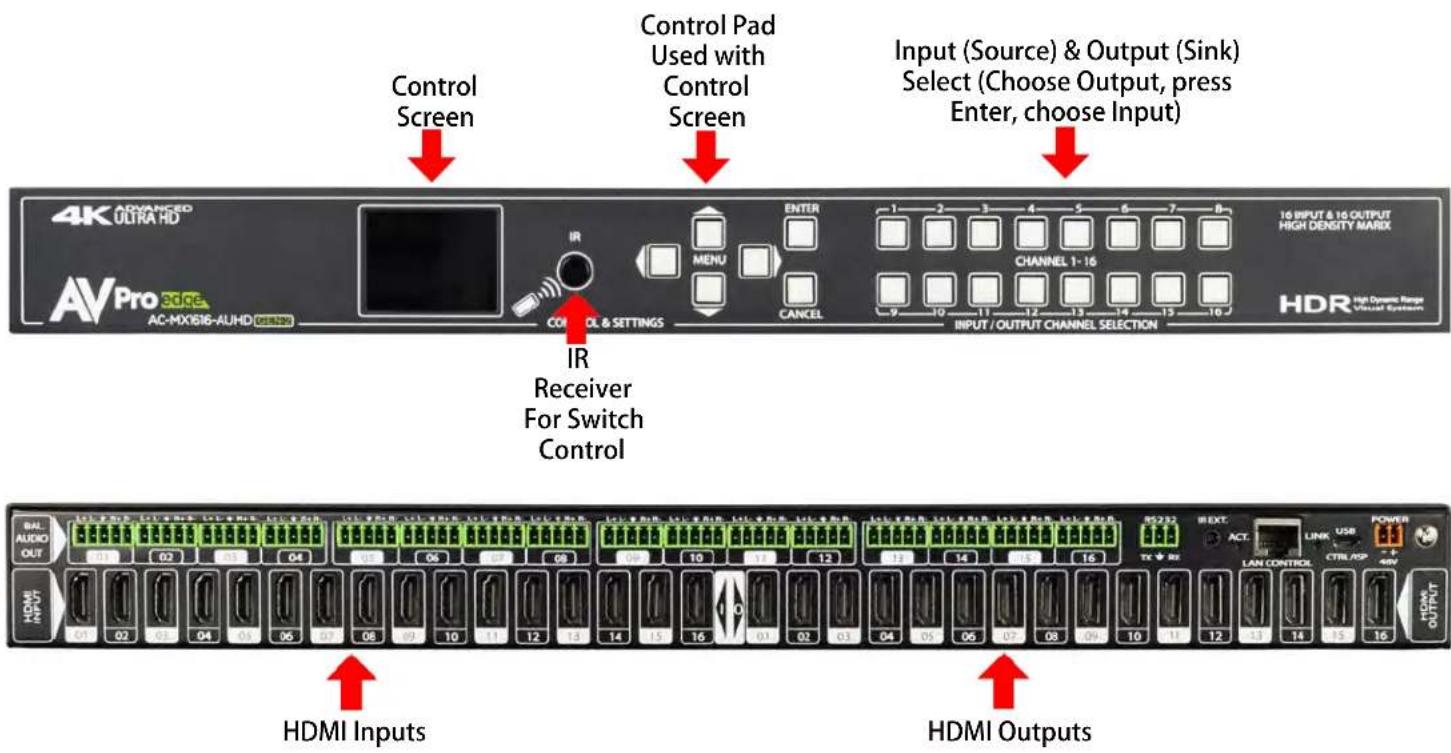
Basic Setup:
Quick Setup:
- Connect the HDMI input sources (Blu-ray, Set Top Box, etc...) to the AC-MX1616-AUHD-GEN2
- Connect the HDMI output devices (AVR, Display, Distribution Amplifier, Extender) to the AC-MX1616-AUHD-GEN2
- Power on the sources
- Connect the power supply's into the AC-MX1616-AUHD-GEN2 (You need to plug in both supply's)
- Turn on output devices/displays
- You may now use the front panel controls, supplied IR remote or free PC software to control the switch.
Front Panel Control
Switching:
The AC-MX1616-AUHD-GEN2 can be switched from the front panel by selecting the OUTPUT, Press ENTER, then select the INPUT:
- Press the button (1 through 16) that corresponds with the OUTPUT (Display, or Sink Device) you would like to send a source.
- Press ENTER
- Now select the desired INPUT on (1 through 16)
- The route is now set.
- You may also navigate to the "Switch" Menu on the Control Screen to manage the routes (See "Switch Routing" below)
STEP 2: Press ENTER STEP 1: Select the desired OUTPUT
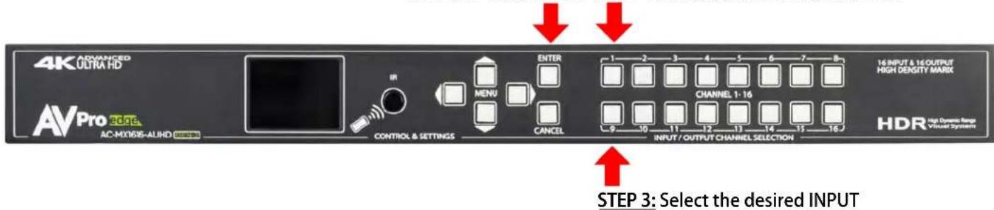
Switching with the front panel controls.
NOTE: Select the OUTPUT, press ENTER, and then select the INPUT
Navigating the Control Screen:
You can use the control screen to setup/control several key features including:
- Matrix Switch Routing \~ Control switching or view the current routing
• EDID Management \~ View, adjust EDID Configuration - Audio Setup & Routing \~ Set the default extracted audio mode to Bind to Input, Bind to Output or Matrix - When in Matrix, audio route can be selected.
- Network Setup \~ View/Setup IP Address (Host/device, Gateway, Subnet), Toggle DHCP, set port number and view MAC Address
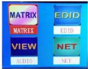
Home Screen
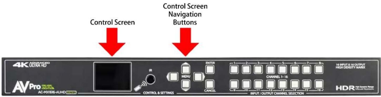
To navigate the control screen you have a 6-button control panel that control the "Control" Screen.
- "Menu" area consists of UP, DOWN, LEFT and RIGHT - These are your navigation buttons. Press these buttons to move through them menus to your desired selections. Your desired selection will be bordered or highlighted
- "Enter" Selects the highlighted item and advances to the next set of options or sets your selection
- "Cancel" Stops what you are doing and takes you back one menu or to the home screen.
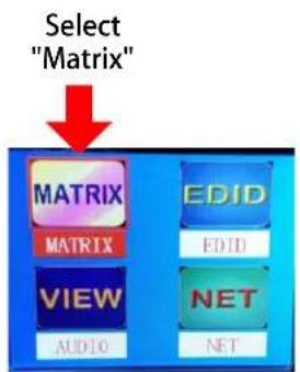
Control Screen - Switch Routing:
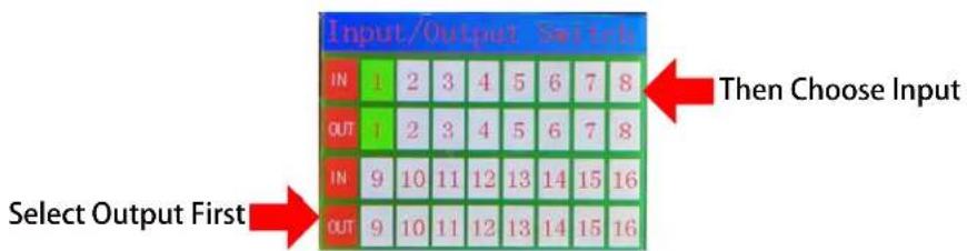
Once you select the "Matrix" option, you have 2 primary functions:
- View the current rout settings so you can verify that your system is working properly and the routes are correct
- Set new matrix routes. You can change the matrix routes here as well, this is good for demonstrating switching. NOTE: When setting a new route, select OUTPUT first then INPUT
flowchart
graph TD
    A["Select "Matrix""] --> B["MATRIX"]
    A --> C["VIEW"]
    A --> D["AUDIO"]
    A --> E["EDID"]
    A --> F["NET"]
    A --> G["NET"]
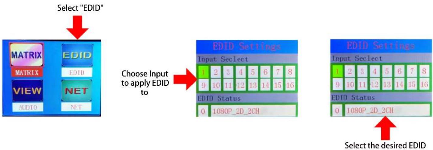
Control Screen - EDID Management:
Instantly and easily set and manage EDID functions right from the front screen. EDID management will help you get the right signal from the source device adding additional security that nothing unsupported will be mistakenly fed into the system.
EDID effectively tells the source what the system is capable of handling, devices without robust EDID control just have to hope the source behaves how we want it to. With the AC-MX1616-AUHD you control the sources:
To Set the EDID, just choose EDID from the "Home Screen" and then select the INPUT you want to set. Finally toggle through the EDIDs until you get the one you want. For the most plug and play compatibility, we recommend using "1080P 2CH" (Which is the default setting). This is ideal for bars, restaurants, and homes. There is also the ability to upload a custom EDID is desired (Has to be done in Serial Control Software).
Available EDID options are listed below. Additionally, you can copy an EDID from a display using Serial (more later in this manual) - This is recommended for advanced users doing HDR distribution.
flowchart
graph TD
    A["Select "EDID""] --> B["Choose Input to apply EDID to"]
    B --> C["EDID Settings"]
    C --> D["EDID Settings"]
    D --> E["Select the desired EDID"]
Available EDID's:
- 1080P_2CH
- 1080P_6CH
- 1080P_8CH
- 1080P_3D_2CH
- 1080P_3D_6CH
- 1080P_3D_8CH
- 4K30HZ_3D_2CH
- 4K30HZ_3D_6CH
- 4K30HZ_3D_8CH
10.4K60HzY420_3D_2CH - 4K60HzY420_3D_6CH
- 4K60HzY420_3D_8CH
- 4K60HZ_3D_2CH
- 4K60HZ_3D_6CH
- 4K60HZ_3D_8CH
- 1080P_2CH_HDR
-
1080P_6CH_HDR
-
1080P_8CH_HDR
- 1080P_3D_2CH_HDR
- 1080P_3D_6CH_HDR
- 1080P_3D_8CH_HDR
- 4K30HZ_3D_2CH_HDR
- 4K30HZ_3D_6CH_HDR
- 4K30HZ_3D_8CH_HDR
- 4K60HzY420_3D_2CH_HDR
- 4K60HzY420_3D_6CH_HDR
- 4K60HzY420_3D_8CH_HDR
- 4K60HZ_3D_2CH_HDR
- 4K60HZ_3D_6CH_HDR
- 4K60HZ_3D_8CH_HDR
- User EDID 1
- User EDID 2
- User EDID 3
Control Screen - Audio Settings
Audio Settings has two functions:
Function 1 - Set the default extracted audio mode. There are three options:
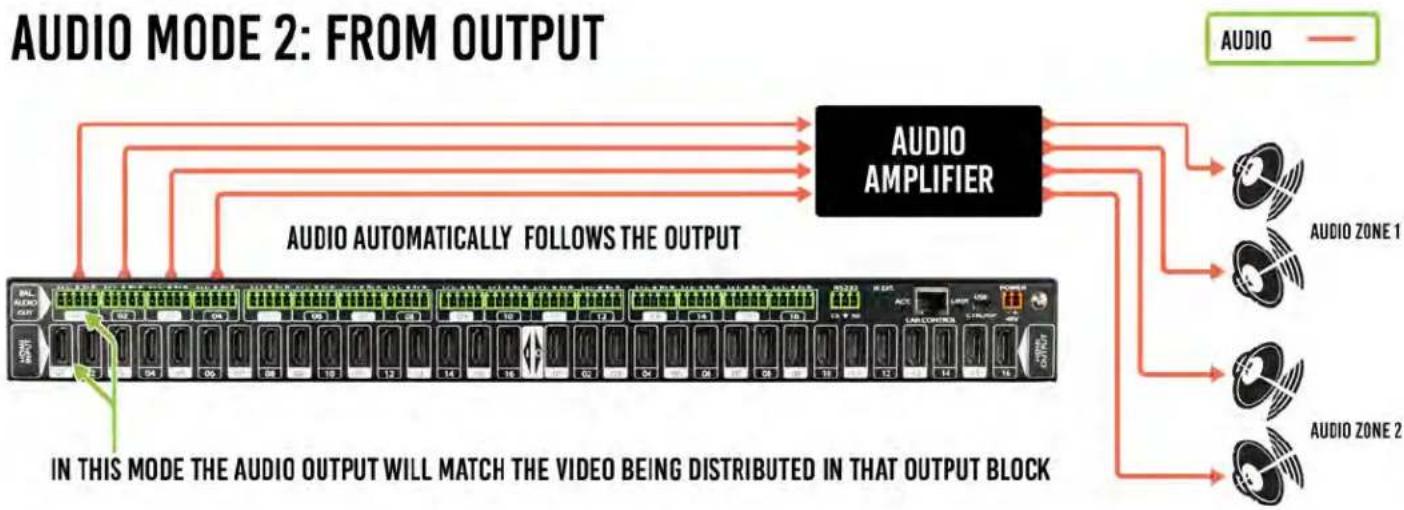
- Bind to output (extracted audio witches with the video, this is the default mode)
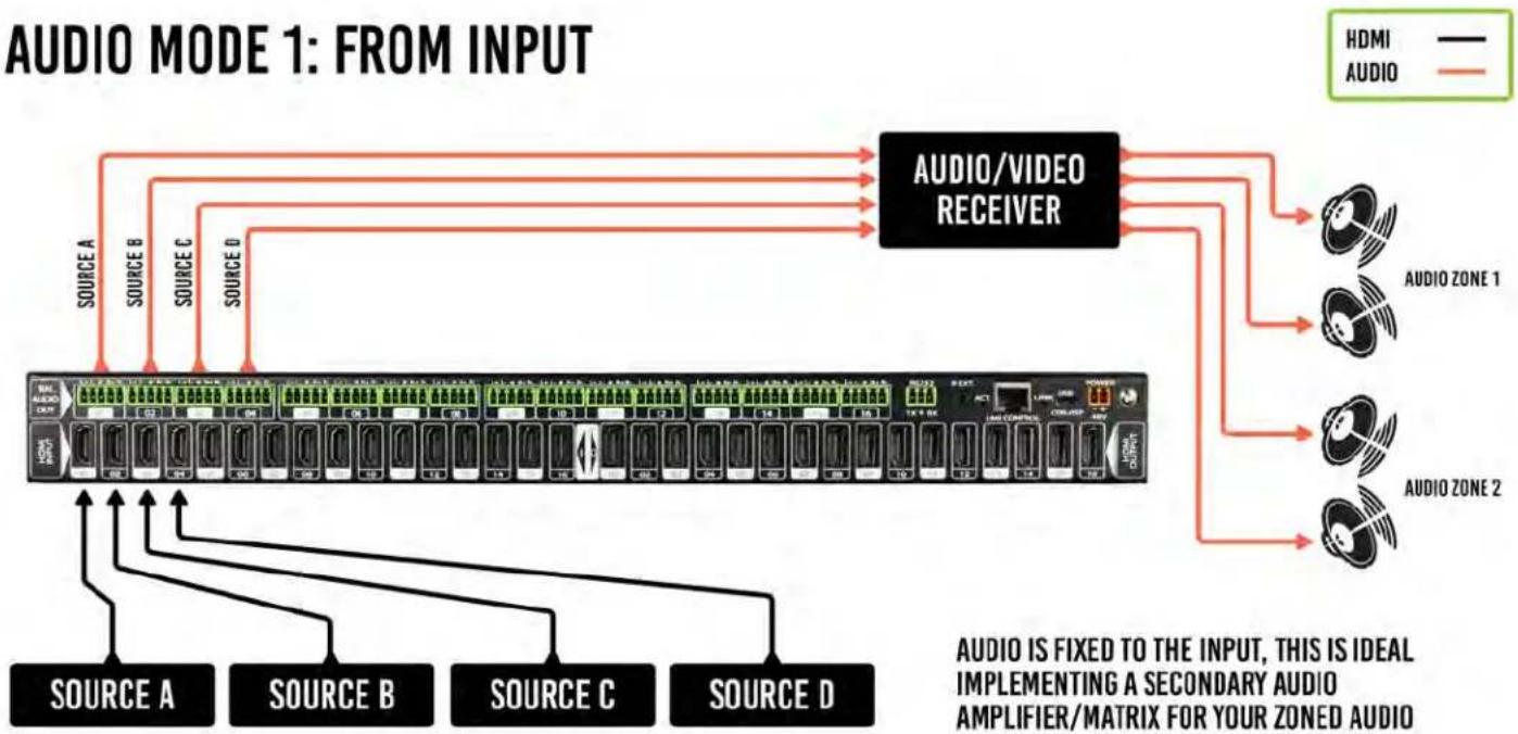
- Bind to input (extracted audio is fixed to the corresponding input by the same number)
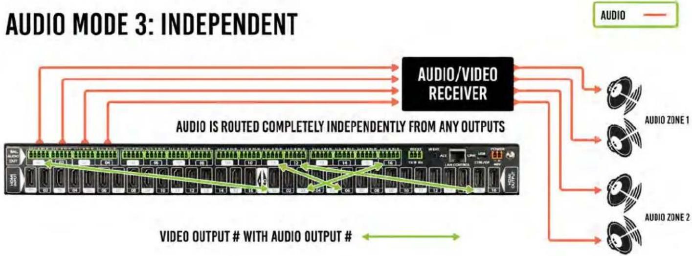
- Independent/Matrix (extracted audio can be routed however you like and there are commands to allow it to function as a separate matrix)
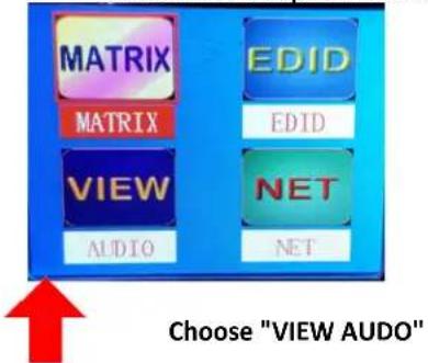
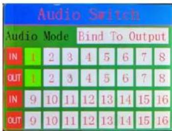

Highlight this area and press "ENTER". You can now toggle up and down to select the mode.
Function 2 - View/Route Extracted Audio Matrix. (NOTE: you can only route the audio if "MATRIX" mode is selected above. To route audio, follow the same logic as video switching in this menu:
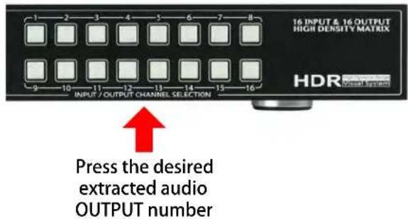
- Select the extracted audio OUTPUT first by pressing the number or navigating to it
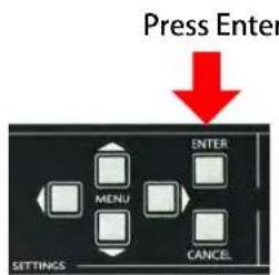
- Press ENTER to set the selection
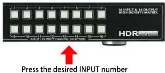
- Select the desired INPUT by toggling to it with UP/DOWN or simply selecting the number on the keypad.
- Press ENTER (This only applies if you used up/down to toggle to your desired input)
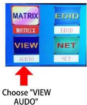
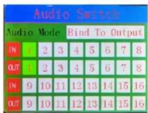

Make sure this area says MATRIX
Control Screen - Network (IP) Setting
Here you can setup the Matrix with your preferred network settings. From the front panel you can:
• View the current IP Settings and MAC address
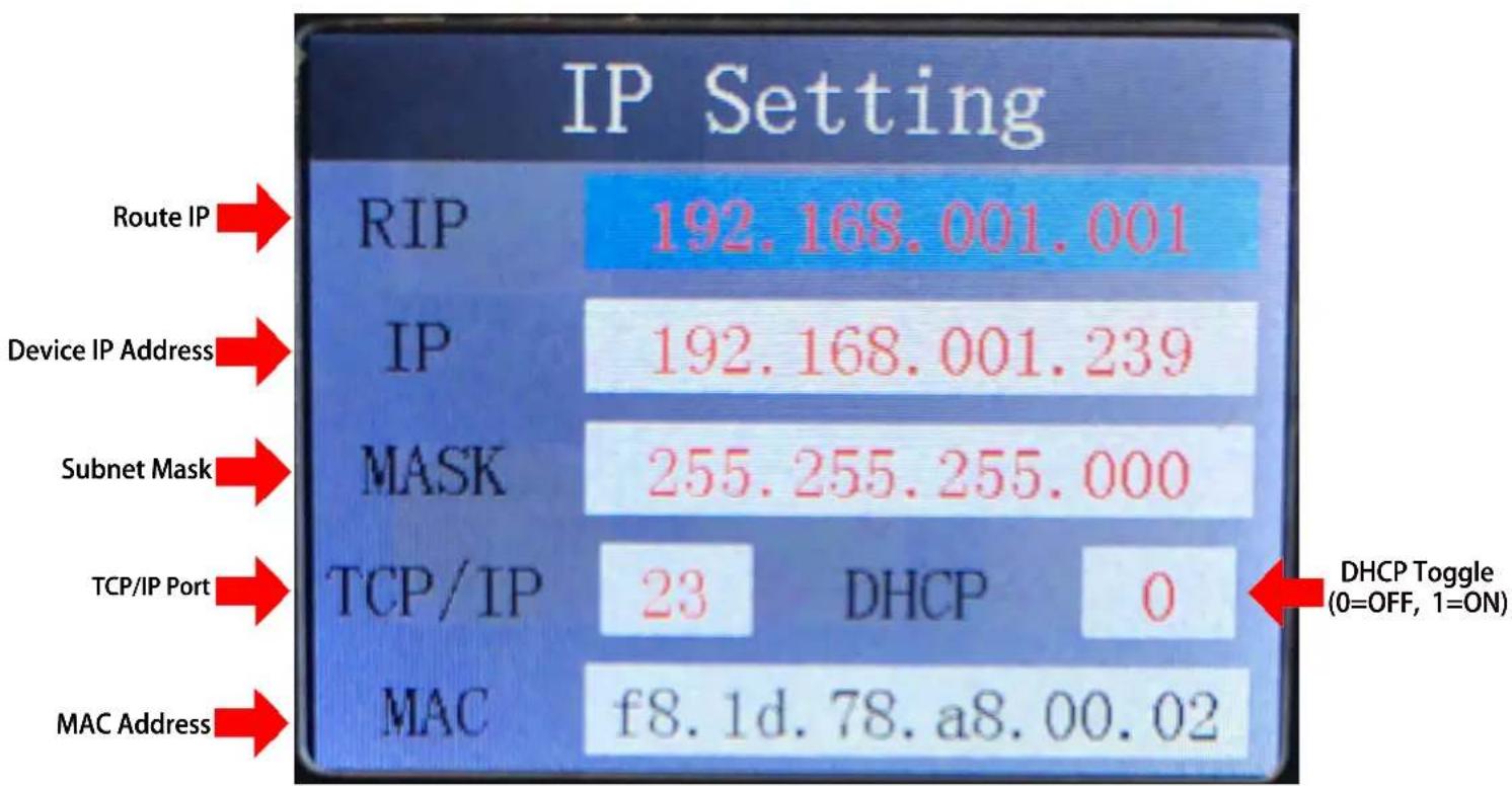
- Set static Route IP (Default is 192.168.001.001)
- Set static Device IP (Device Default is 192.168.001.239)
- Set Static Net Mask (Default is 255.255.255.0)
- Change the TCP/IP Port (Default is Port 23)
- Toggle DHCP (Default condition is DHCP OFF) (0=OFF, 1=ON)
To navigate the IP Setting Screen:
- Navigate up and down to select (Use Enter Button) the option you want to address (RIP, IP, Mask, TCP.IP, DHCP)
- Once selected you can use up and down to to change the first number or press enter to skip it and continue to the next.
- Once you set the last possible number (Or complete the IP) it will back you to the main screen to make another selection
NOTE: You can send Telnet commands to the machine by IP, the commands are the same commands used for RS232 listed in the "Command List"
other
IP Setting | Protocol | IP | Value | | :--- | :--- | :--- | | Route IP | RIP | 192.168.001.001 | | Device IP Address | IP | 192.168.001.239 | | Subnet Mask | MASK | 255.255.255.000 | | TCP/IP Port | TCP/IP | 23 DHCP 0 | | MAC Address | MAC | f8.1d.78.a8.00.02 | DHCP Toggle (0=OFF, 1=ON)IR Details:
IR IN on this machine is for controlling the AC-MX1616-AUHD, RS232 or IP Control are the recommended methods, but IR can be used in some circumstances. The IR INPUT is for an IR Receiver EYE only. The IR Receiver Eye below can plug into the IR Ext. port.
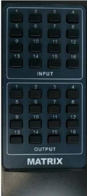
- Use the supplied IR Remote (Pictured) and select the OUTPUT then INPUT
- Lear IR Codes from the supplied remote
- Use discreet NEC/HEX IR Codes to program a 3rd party control system or IR remote. Check www.avproedge.com for discreet IR codes, or contact us to get them.
IR Remote Control:
The Matrix can be switched with IR Commands (Remote or other) in several ways:
RS-232 and TCP/IP Commands:
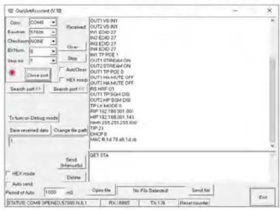
The AC-MX1616-AUHD-GEN2 can be controlled with either RS-232 or TCP/IP commands. Certain switching or format configurations can only be done using these commands. We recommend using either the MyUART (RS-232 - free) or Hercules (TCP/IP - free) apps as they are very easy to use for sending commands to the machine.
For TCP/IP control commands use Telnet Port 23.
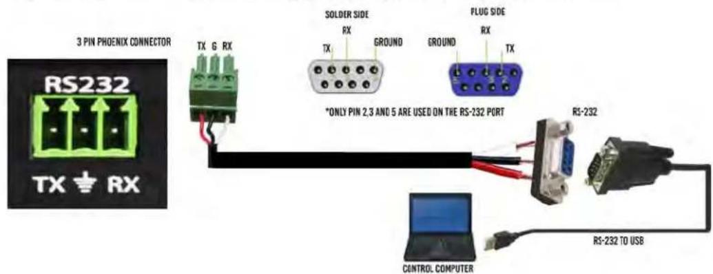
For RS-232, use a null modem serial cable adapter and set the serial communications to: 57600,n,8,1 (baud: 57600, no parity, 8 data bits and 1 stop bit) with no handshaking.
Please add a return (Enter key) after each command when using direct commands.
The unified command list (ASCII) is listed below.
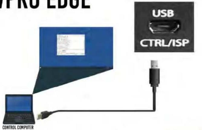
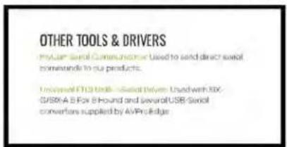
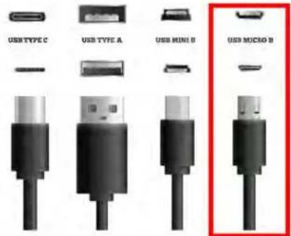
USB CONTROL FOR AVPRO EDGE
WWW.AVPROEDGE.COM/DRIVERS
RS-232 CABLE FOR AVPRO EDGE
RS-232 and TCP/IP Commands:
The Matrix can be controlled with either RS-232 or TCP/IP commands. Certain switching or format configurations can only be done using these commands. We recommend using either the MyUART (RS-232 - free) or Hercules (TCP/IP - free) apps as they are very easy to use for sending commands to the machine.
For TCP/IP control commands use Telnet Port 23.
For RS-232, use a null modem serial cable adapter and set the serial communications to:
57600,n,8,1 (baud: 57600, no parity, 8 data bits and 1 stop bit) with no handshaking.
Please add a return (Enter key) after each command when using direct commands. The unified command list (ASCII) is listed on the next page.
Command Example: DHCP and setting the IP Address
- Connect your computer to one of the control ports (Micro USB/3pin Terminal)
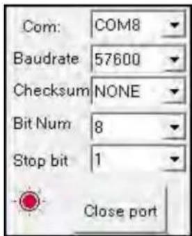
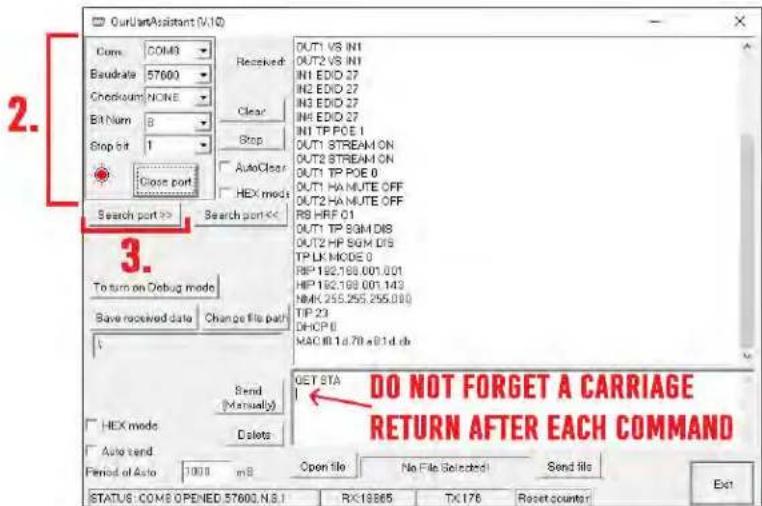
- Open up MyUart and verify the correct settings
a. Baudrate: 57600, no parity, 8 data bits and 1 stop bit) with no handshaking. - On MyUart click Search Port>> (you will see a red indicator once connected)
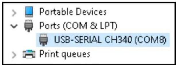
a. You can verify the COM port by using Windows Device Manger. Both USB and 3pin connections should show up as a COM#. - Send "GET DHCP" with a carriage return (no " " and hit Enter/Return on keyboard).
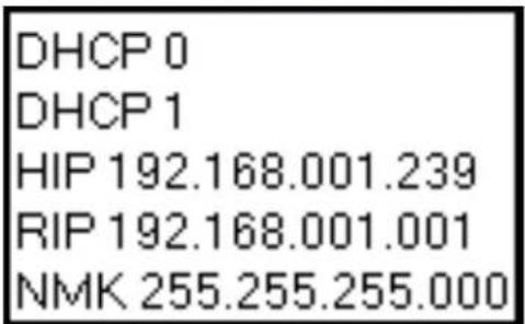
a. Default is OFF so the return message should be "DHCP 0" (0=Off, 1=On) - Send "SET DHCP 1", the return message should read "DHCP 1"
a. This will also return the current IP Settings. If there is no connection it will reply with the Default Settings. - You can now connect to the WebUI by typing in the HIP address into a web browser. There you can alter the IP address of the Matrix to one of your choosing.
- You can also set the address of the matrix by sending the following command
a. "SET HIP xxx.xxx.xxx.xxx" (SET HIP 192.168.1.143) -
Once configured it is recommended to turn DHCP back off so the settings are set to Static and will not change (this can also be done from the WebUI).
a. "SET DHCP 0" -
You can verify the settings by getting the status of the matrix
a. "GET STA"
RS-232andTCP/IPCommands:
| Command | Action |
| H | : Help |
| STA | : Show Global System Status |
| SET RST | : Reset to Factory Defaults |
| SET RBT | : System Reset to Reboot |
| SET ADDR xx | : Set System Address to xx {xx=[00-99](00=Single)} |
| SET EMG MODE EN/DIS | : Set Emergency Mode Enable/Disable |
| SET LCD ON Tx | : Set LCD Remain On Time{x=[0~3](0=Always ON,1=15,2=30,3=60Sec)} |
| SET KEY LOCK ON/OFF | : Set Key Lock On/Off |
| GET ADDR | : Get System Address |
| GET EMG MODE | : Get Emergency Mode Status |
| GET STA | : Get System System Status |
| GET INx SIG STA | : Get Input x Signal Status{x=[0~8](0=ALL)} |
| GET INx VID FMT INF | : Get Input x Video Format Info{x=[0-16](0=ALL)} |
| GET LCD ON T | : Get LCD Remain On Time |
| GET KEY LOCK | : Get Key Lock Status |
| Output Setup Commands: | (Note:output number(x)=HDMI(x),x=1-16) |
| SET OUTx VS INy | : Set Output x To Input y {x=[0~16](0=ALL), y=[1~16]} |
| SET OUTx EXA EN/DIS | : Set Ex-Audio Output Enable/Disable{x=[0~16](0=ALL)} |
| SET OUTx EXADL PHY | : Set Ex-Audio Delay{x=[0~16](0=ALL), y=[0~7](0=Bypass,1~7=90,180,270,360,450,540,630MS)} |
| SET EXAMX MODEx | : Set Ex-Audio Matrix Mode{x=[0~2](0=Bind To Output,1=Bind To Input,2=Matrix} |
| SET OUTx AS INy | : Set Ex-Audio Output x To Input y{x=[0~16](0=ALL), y=[1~16]} |
| SET OUTx EXAUD LEVy | : Set Output x EQ-Audio Volume Level{x=[0-16](0=all),y=[0~20]} |
| SET OUTx STREAM ON/OFF | : Set Output x Stream ON/OFF{x=[0~16](0=ALL), y=[1~16]} |
| SET OUTx SGM EN/DIS | : Set Output x Signal Generator Enable/Disable{x=[0~16](0=ALL)} |
| GET OUTx VS | : Get Output x Video Route {x=[0~16](0=ALL)} |
| GET OUTx EXA | : Get Ex-Audio Output Enable/Disable Status{x=[0~16](0=ALL)} |
| GET OUTx EDID DATA | : Get Output x EDID DATA{x=[1~16]} |
| GET EXAMX MODE | : Get Ex-Audio Matrix Mode |
| GET OUTx AS IN | : Get Output x Ex-Audio Route{x=[0~16](0=ALL)} |
| GET OUTx EXAUD LEV | : Get Output x EQ-Audio Volume Level{x=[0-16](0=all)} |
| GET OUTx STREAM | : Get Output x Stream ON/OFF Status{x=[0~16](0=ALL)} |
| GET OUTx SGM | : Get Output x Signal Generator Status{x=[1-16](0=ALL)} |
Command List cont:
Settings: Baud Rate 57600, Data Bits 8, No Parity, 1 Stop Bit
NOTE - Visit www.avproedge.com to get the Notepad version of the command list for easy copy/past access.
| Input Setup Commands: | (Note:input number(x)=HDMI(x),x=1-16) | |
| SET INx EDID y | : Set Input x EDID {x=[0~16](0=ALL),y=[0~32]} | |
| 0:1080P_2CH(PCM) | 1:1080P_6CH | 2:1080P_8CH |
| 3:1080P_3D_2CH(PCM) | 4:1080P_3D_6CH | 5:1080P_3D_8CH |
| 6:4k30Hz_3D_2CH(PCM) | 7:4k30Hz_3D_6CH | 8:4k30Hz_3D_8CH |
| 9:4K60Hz(Y420)_3D_2CH(PCM) | 10:4K60Hz(Y420)_3D_6CH | 11:4K60Hz(Y420)_3D_8CH |
| 12:4K60HZ_3D_2CH | 13:4K60HZ_3D_6CH | 14:4K60HZ_3D_8CH |
| 15:1080P_2CH(PCM)_HDR | 16:1080P_6CH_HDR | 17:1080P_8CH_HDR |
| 18:1080P_3D_2CH(PCM)_HDR | 19:1080P_3D_6CH_HDR | 20:1080P_3D_8CH_HDR |
| 21:4K30Hz_3D_2CH(PCM)_HDR | 22:4K30Hz_3D_6CH_HDR | 23:4K30Hz_3D_6CH_HDR |
| 24:4K60Hz(Y420)_3D_2CH(PCM)_HDI | 25:4K60Hz(Y420)_3D_6CH_HDR | 26:4K60Hz(Y420)_3D_8CH_HDR |
| 27:4K60Hz_3D_2CH(PCM)_HDR | 28:4K60Hz_3D_6CH_HDR | 29:4K60Hz_3D_8CH_HDR |
| 30:USER1_EDID | 31:USER2_EDID | 32:USER3_EDID |
| SET INx EDID CY OUTy | : Copy Output y EDID To Input x(USER1 BUF){x=[0~16](0=ALL),y=[1~16]} | |
| SET INx EDID Uy DATAz | : Write EDID To User y Buffer of Input x{x=[0~16](0=ALL),y=[1~3],z=[EDID Data]} | |
| SET INx TMDS ON/OFF | : Set Input x Port Power Status ON/OFF {x=[0~16](0=ALL) | |
| GET INx EDID | : Get Input x EDID Index{x=[0~16](0=ALL)} | |
| GET INx EDID y DATA | : Get Input x EDID y Data{x=[1~16],y=[0~32]} | |
| GET INx TMDS | : Get Inputx Port Power Status{x=[0~16](0=ALL) | |
| Preset Group Command: | (Note:Output number(x)=HDMI(x),x=1-16) | |
| SET VS PSMx | : Set Preset Mode x {x=[1~10]} | |
| SET VS SSMx | : Set Current State to Preset Mode x {x=[1~10]} | |
| SET GUP PSMx OUT zz | : Set Preset Mode Group x All Output To Input{x=[1~10],z1-z1 6[Input]} | |
| : zz={z1.z2.z3.z4.z5.z6.z7.z8.z9.z10.z11.z12.z13.z14.z15.z16} | ||
| GET VS PSMx | : Get Preset Mode x Status{x=[1~10]} | |
| GET GUP PSMx OUT | : Get Preset Mode Group x All Output Status {x=[0~10](0=ALL)} | |
| Network Setup Command: | :(xxx=[000-255],zzzz=[0001~9999] | |
| SET RIP xxx.xxx.xxx.xxx | : Set Route IP Address to xxx.xxx.xxx.xxx | |
| SET HIP xxx.xxx.xxx.xxx | : Set Host IP Address to xxx.xxx.xxx.xxx | |
| SET NMK xxx.xxx.xxx.xxx | : Set Net Mask to xxx.xxx.xxx.xxx | |
| SET TIP zzzz | : Set TCP/IP Port to zzzz | |
| SET DHCP y | : Set DHCP {y=[0~1](0=Dis,1=Enable)} | |
| GET RIP | : Get Route IP Address | |
| GET HIP | : Get Host IP Address | |
| GET NMK | : Get Net Mask | |
| GET TIP | : Get TCP/IP Port | |
| GET DHCP | : Get DHCP Status | |
| GET MAC | : Get MAC Address | |
| IR Code Setup: | ||
| SET IR SYS xx yy | : Set IR System Code {xx=[00~FFH],yy=[00~FFH]} | |
| SET IR OUTx INy CODE zz | : Set IR Data Code {x=[1~16],y=[1~16],zz=[00~FFH]} | |
| GET IR SYS | : Get IR System Code | |
| GET IR OUTx INy CODE | : Get IR Data Code {x=[0~16](0=All),y=[1~16]} | |
Using Multiple Units In One System:
Device Addresses When Using Serial Communication:
NOTE: Only set device address when cascading multiple units together and using RS232 as your control method! You also have to send the device address when doing advanced routing while sending commands by serial (next page) even if it is default "A00". You NEVER use device addresses when using IP control or TELNET
When using serial communication it is good to be aware of the devices "Address" You will want to know the device address as this will determine which AC-MX1616-AUHD will receive a command. All of the drivers are built so that if you use serial communication you will use ONE instance of the driver and select the size. i.e 9x18, 9x27 etc...
All AC-MX1616-AUHD are address "A00" by default and if you are using just one device you do not need to place this in front of the serial command.
EX1: If you have a standalone unit and are using serial control you can just send a command without the address:
"SET OUT5 VS IN3" ----This will set Output 5 to Input 3
EX2: If you have two units in a system you have to label them A01 and A02, so a command will look like:
"A02SET OUT5 VS IN3" ----This will set Output 5 to Input 3 ON SWITCH TWO. Also, please note that there is no "space" between the address and the command
To set and device address you can use the PC Control Software or send the command "SET ADDR xx" (xx = 01 through 99)
Cascading with IP Control:
With IP you have to have a direct IP connection to each unit, and regard them as individual matrices. So for a 9 units in a system with IP control, you have to connect Ethernet to all 9 matrices. If you are using a 3rd party control driver, install 9 instances of the drivers, and regard them all as individual 16x16 matrices.
When using IP DO NOT use serial system addresses, as the IP addresses will serve the same purpose. While it can be done if one so desires, it complicates the programming.
A best practice is to set a static IP address for each unit, rather than DHCP.
Extracted Audio:
The extracted audio ports have distinct operating modes. Your desired mode can be set to suite your particular installation. The 3 modes are:
From Input \~ This is the default configuration. In this mode the audio port number corresponds to the INPUT signal. This is ideal for systems where audio is matrixed separately in a zoned amplifier.
From Output \~ This configuration will automatically have the audio follow OUTPUT, so the audio from the extracted port always matches the HDMI output. This is ideal for systems that use local AVR's for some of the zones.
Independent/Matrix \~ This mode allows you matrix the extracted audio outputs independent of HDMI. In this mode a new set of commands becomes available to be able to route audio however you want. This can be used as a separate zoned audio matrix with only using an amplifier.
Setting up Extracted Audio Routing:
You can set up Extracted Audio Routing in the PC Software, Driver or by sending the following command:
SET EXA MODEy -- Where (y=0-2) 0=From Input, 1=From Output, 2=Independent.
If you set to "Independent" a new set of commands is available to you to matrix the ports:
SET OUTx EAS INy -- Where (x=0-16) 0=ALL, 1-16=Desired Output & (y=1-16) 1-16=Desired Input
NOTE: Extracted Audio Ports are PCM 2CH audio up to LPCM 6 CH, Dolby Digital 5.1 & DTS. No down-mix.
flowchart
graph TD
    A["Input Source"] --> B["Source A"]
    A --> C["Source B"]
    A --> D["Source C"]
    A --> E["Source D"]
    B --> F["Audio/Video Receiver"]
    C --> F
    D --> F
    E --> F
    F --> G["Output Zone 1"]
    F --> H["Output Zone 2"]
    F --> I["Output Zone 3"]
    style A fill:#f9f,stroke:#333
    style F fill:#ccf,stroke:#333
Extracted Audio cont:
Audio Diagrams:
flowchart
graph TD
    A["Audio"] --> B["Audio AMPLIFIER"]
    B --> C["IN THIS MODE THE AUDIO OUTPUT WILL MATCH THE VIDEO BEING DISTRIBUTED IN THAT OUTPUT BLOCK"]
    C --> D["AUDIO ZONE 1"]
    C --> E["AUDIO ZONE 2"]
    C --> F["AUDIO"]
    style A fill:#f9f,stroke:#333
    style B fill:#ccf,stroke:#333
    style C fill:#cfc,stroke:#333
    style D fill:#fcc,stroke:#333
    style E fill:#fcc,stroke:#333
    style F fill:#fcc,stroke:#333
flowchart
graph TD
    A["Audio"] --> B["Audio/Video Receiver"]
    B --> C["Audio Zone 1"]
    B --> D["Audio Zone 2"]
    B --> E["Video Output #"]
    F["Video Output #"] --> G["Audio OUTPUT #"]
    H["Audio is Routed Completely Independently from any Outputs"] --> B
    style A fill:#f9f,stroke:#333
    style F fill:#ccf,stroke:#333
    style G fill:#cfc,stroke:#333
    style H fill:#fcc,stroke:#333
PC Control Software - Side Bar:
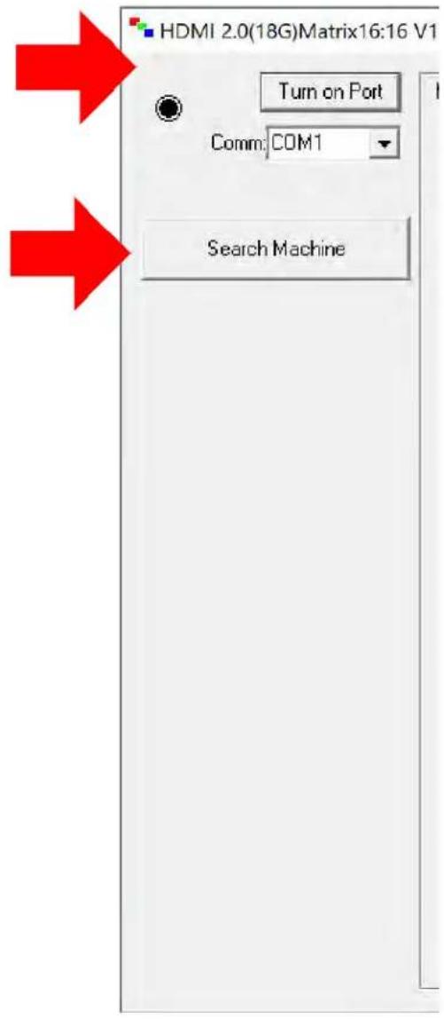
Note: PC Control Software can be used when connected to the RS232 or Mini USB Port.
Connection Area - Use the drop down to select the COM Port or press "Search Machine" to search your computer for open COM Ports. The light will be red if there is a successful connection.
Select/Manage Addresses - Use the drop down to select the Address of the device you want to control (If cascading multiple units). Press "Address Management" to set the Addresses. View "Address Management" Tab later for more.
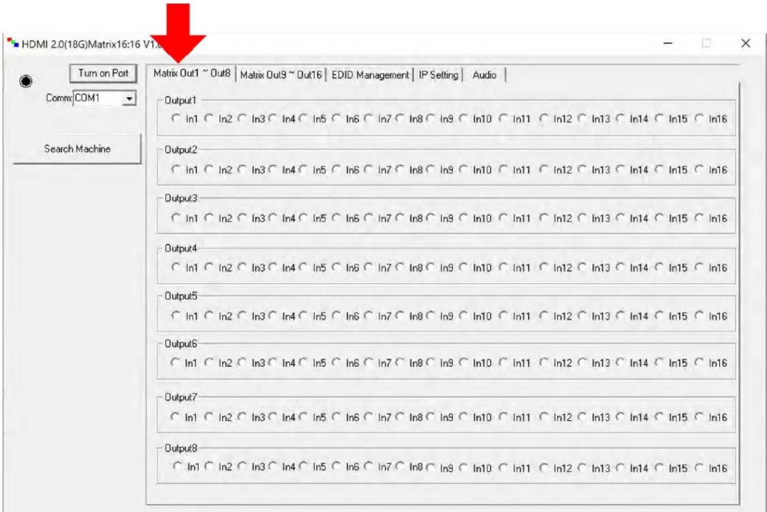
PC Control Software - Matrix Tab (OUTPUT 1-8):
Note: PC Control Software can be used when connected to the RS232 or Mini USB Port.
Switching - Simply choose the INPUT radio button you want to see on each output.
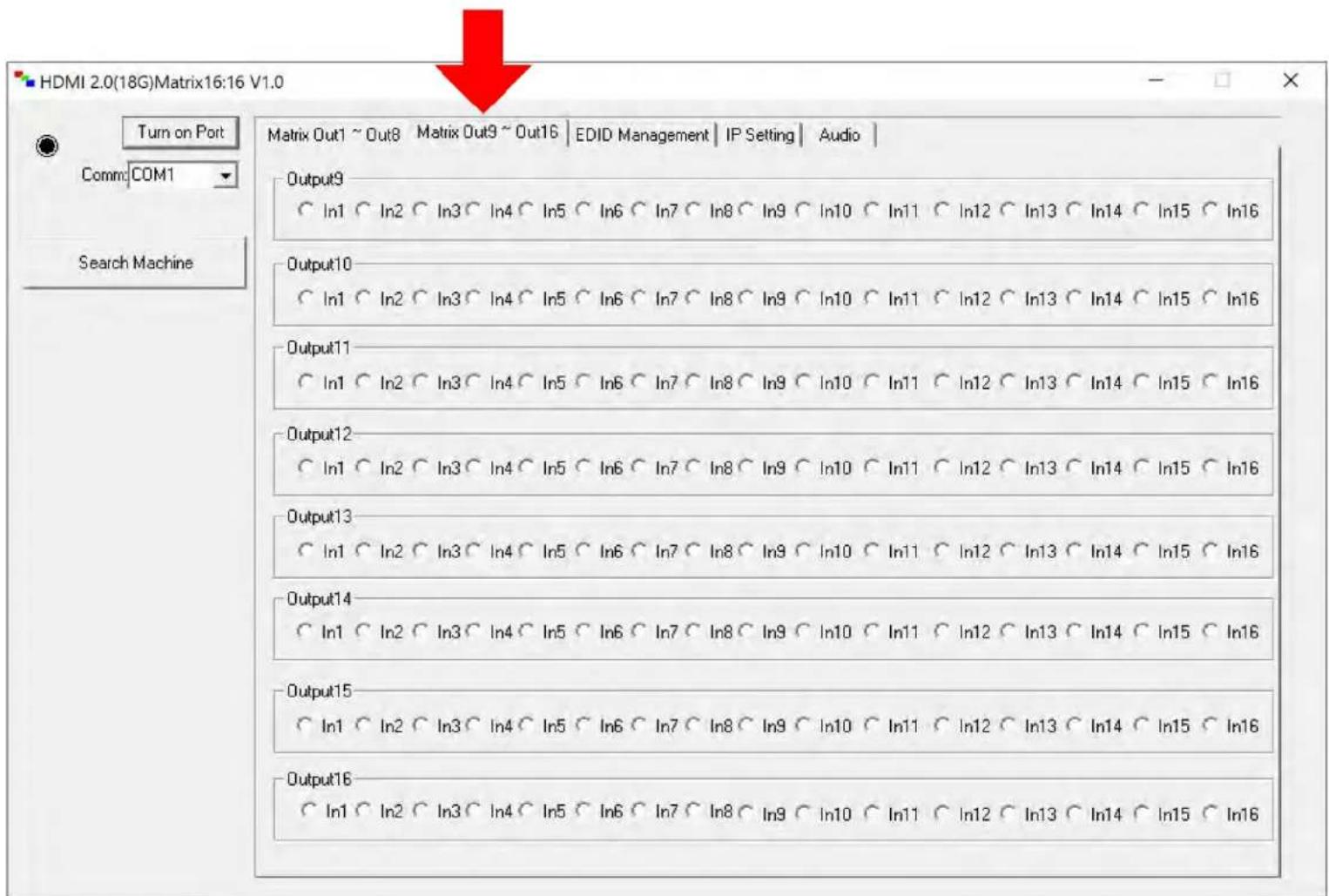
PC Control Software - Matrix Tab (OUTPUT 9-16):
Note: PC Control Software can be used when connected to the RS232 or Mini USB Port.
Switching - Simply choose the INPUT radio button you want to see on each output.
PC Control Software - EDID Tab:
Note: PC Control Software can be used when connected to the RS232 or Mini USB Port.
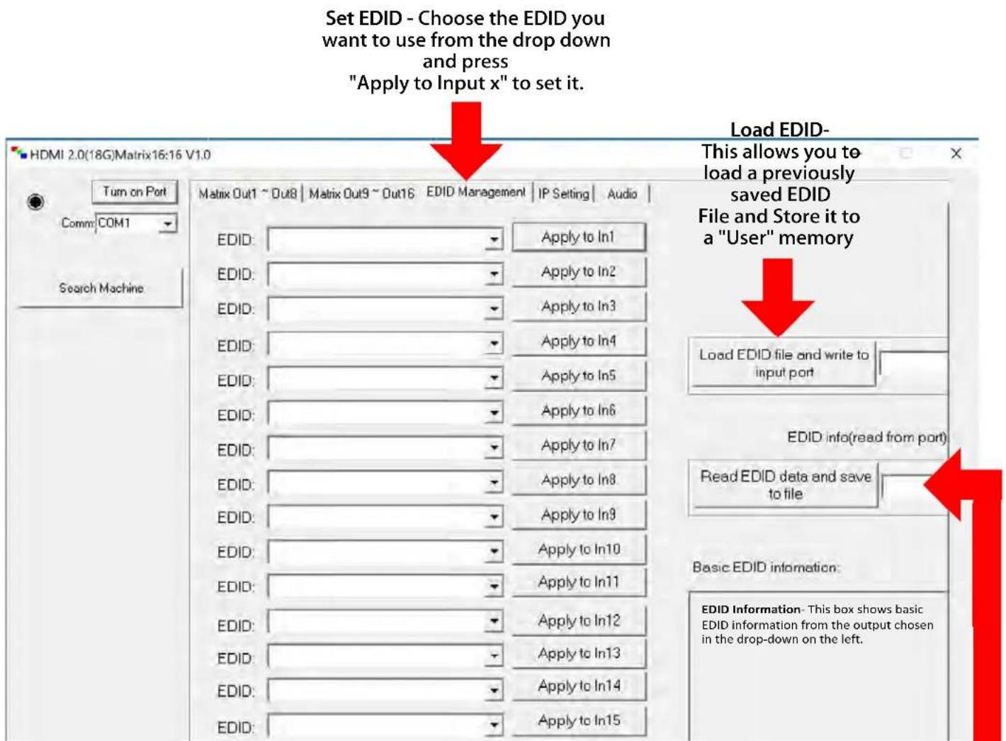
Read EDID and save as file- Select the Output from the drop-down and click the button to save the EDID as a file, you can upload the EDID later and apply it to one of the "USER" EDIDs. You can then apply that USER EDID to one or more of the inputs.
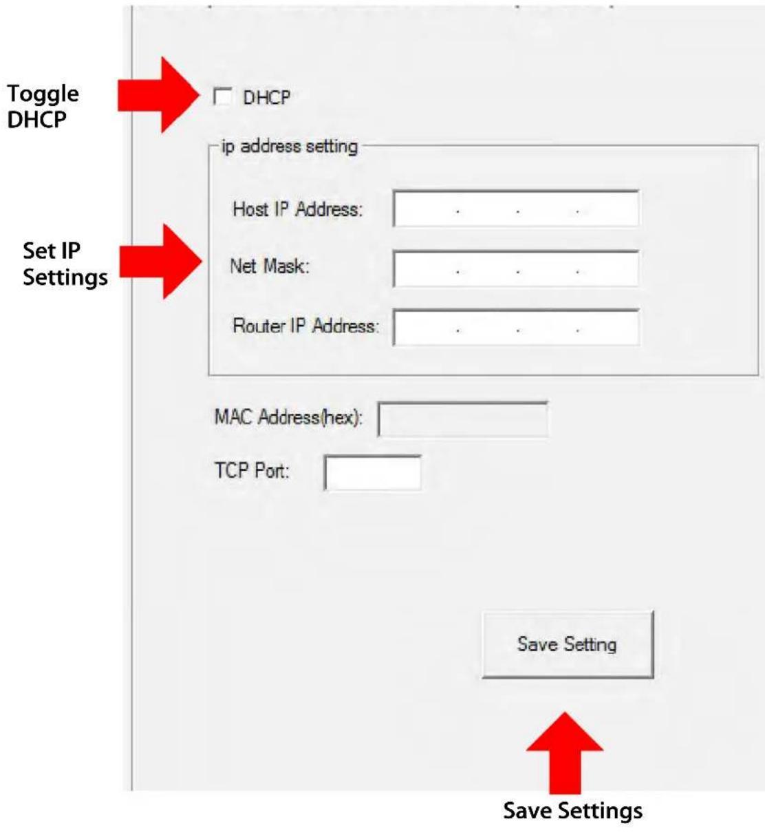
PC Control Software - IP Config Tab:
Note: PC Control Software can be used when connected to the RS232 or Mini USB Port.
flowchart
graph TD
    A["Toggle DHCP"] --> B["DHCP"]
    C["Set IP Settings"] --> D["ip address setting"]
    D --> E["Host IP Address: . . . ."]
    D --> F["Net Mask: . . . ."]
    D --> G["Router IP Address: . . . ."]
    H["MAC Address(hex): "] --> I["TCP Port: "]
    J["Save Setting"] --> K["Save Settings"]
Web Interface: Sense Switch
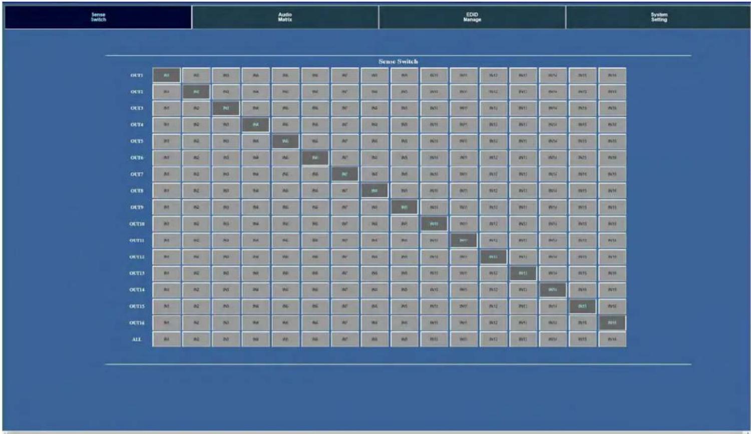
To access the Web Interface, simply type in the IP address of the device. The default IP address 192.168.001.239, if you have setup a different IP or are not sure simply view the "Net" section on the control screen on the front panel. If you enable DHCP, you will want to find the IP address by looking on the setup screen.
The Sense Switch page is the main page of the Web Interface. Here you can easily control switching of the matrix.
NOTE: The inputs and outputs can be labeled in the "System Config" Tab.
Web Interface: Audio Matrix
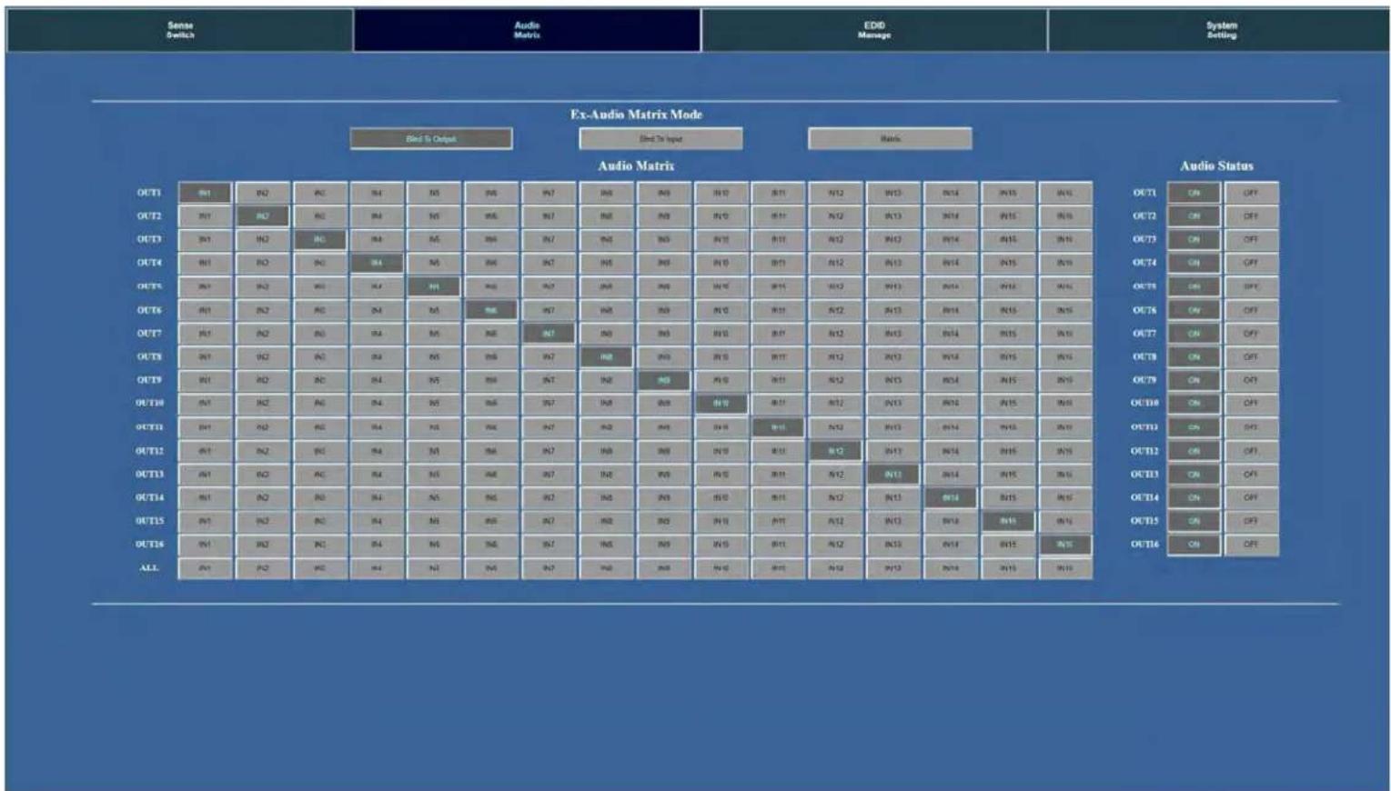
The Audio Setting tab allows to:
1 - Select the Ex-Audio Matrix Mode:
- Bind To Output (Default) \~ Extracted audio will switch with the corresponding HDMI Output of the same number
- Bind To Input \~ Extracted audio will be fixed to the corresponding HDMI Input of the same number (Audio will never switch)
- Matrix \~ Extracted audio can be routed independently of the HDMI Matrix (NOTE: You can only use the "Audio Matrix" control grid when this mode is selected.
2 - Audio Matrix \~ This grid allows you to control the extracted audio route independently of the HDMI route. This function is only available if the Ex-Audio Mode is "Matrix".
3 - Audio Status \~ You can turn each extracted audio port ON or OFF (Mute)
Web Interface: EDID Manage
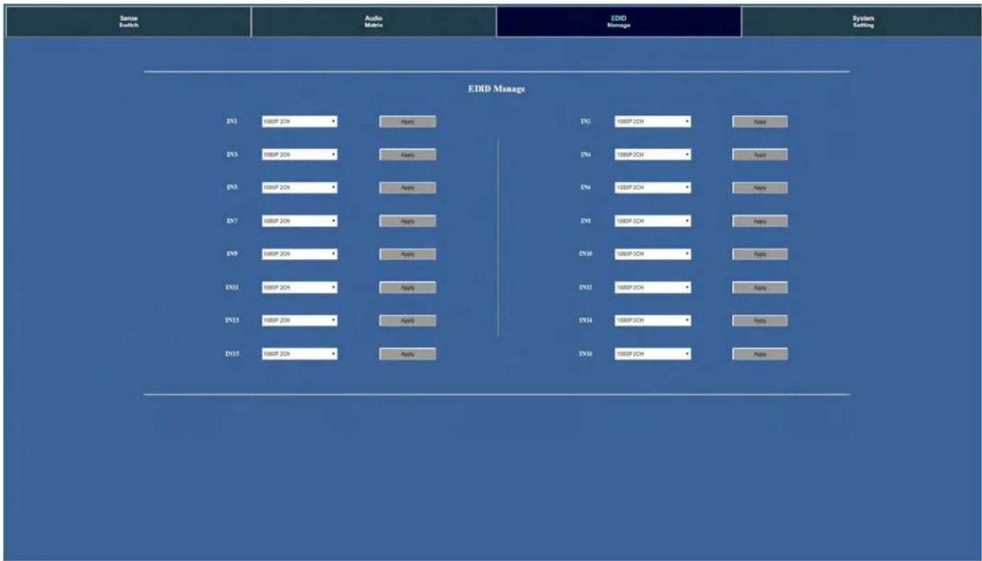
The EDID Manage tab allows you to set the EDID for each input. To set the EDID:
-
Select the desired EDID form the drop down menu of the input you want.
-
Press Apply
flowchart
graph TD
    A["Sense Switch"] --> B["EDID Manage"]
    B --> C["IOF 2OH"]
    B --> D["APN"]
    C --> E["MOF 2OH"]
    C --> F["APN"]
    D --> G["MOF 2OH"]
    D --> H["APN"]
    E --> I["MOF 2OH"]
    E --> J["APN"]
    F --> K["MOF 2OH"]
    F --> L["APN"]
    G --> M["MOF 2OH"]
    G --> N["APN"]
    H --> O["MOF 2OH"]
    H --> P["APN"]
    I --> Q["MOF 2OH"]
    I --> R["APN"]
    J --> S["MOF 2OH"]
    J --> T["APN"]
    K --> U["MOF 2OH"]
    K --> V["APN"]
    L --> W["MOF 2OH"]
    L --> X["APN"]
    M --> Y["MOF 2OH"]
    M --> Z["APN"]
    N --> AA["MOF 2OH"]
    N --> AB["APN"]
    O --> AC["MOF 2OH"]
    O --> AD["APN"]
    P --> AE["MOF 2OH"]
    P --> AF["APN"]
    Q --> AG["MOF 2OH"]
    Q --> AH["APN"]
    R --> AI["MOF 2OH"]
    R --> AJ["APN"]
    S --> AK["MOF 2OH"]
    S --> AL["APN"]
    T --> AM["MOF 2OH"]
    T --> AN["APN"]
    U --> AO["MOF 2OH"]
    U --> AP["APN"]
    V --> AQ["MOF 2OH"]
    V --> AR["APN"]
    W --> AS["MOF 2OH"]
    W --> AT["APN"]
    X --> AU["MOF 2OH"]
    X --> AV["APN"]
    Y --> AW["MOF 2OH"]
    Y --> AX["APN"]
    Z --> AY["MOF 2OH"]
    Z --> AZ["APN"]
Available EDID's:
| 0. 1080P_2CH | 17. 1080P_8CH_HDR |
| 1. 1080P_6CH | 18. 1080P_3D_2CH_HDR |
| 2. 1080P_8CH | 19. 1080P_3D_6CH_HDR |
| 3. 1080P_3D_2CH | 20. 1080P_3D_8CH_HDR |
| 4. 1080P_3D_6CH | 21. 4K30HZ_3D_2CH_HDR |
| 5. 1080P_3D_8CH | 22. 4K30HZ_3D_6CH_HDR |
| 6. 4K30HZ_3D_2CH | 23. 4K30HZ_3D_8CH_HDR |
| 7. 4K30HZ_3D_6CH | 24. 4K60HzY420_3D_2CH_HDR |
| 8. 4K30HZ_3D_8CH | 25. 4K60HzY420_3D_6CH_HDR |
| 9. 4K60HzY420_3D_2CH | 26. 4K60HzY420_3D_8CH_HDR |
| 10. 4K60HzY420_3D_6CH | 27. 4K60HZ_3D_2CH_HDR |
| 11. 4K60HzY420_3D_8CH | 28. 4K60HZ_3D_6CH_HDR |
| 12. 4K60HZ_3D_2CH | 29. 4K60HZ_3D_8CH_HDR |
| 13. 4K60HZ_3D_6CH | 30. User EDID 1 |
| 14. 4K60HZ_3D_8CH | 31. User EDID 2 |
| 15. 1080P_2CH_HDR | 32. User EDID 3 |
| 16. 1080P_6CH_HDR |
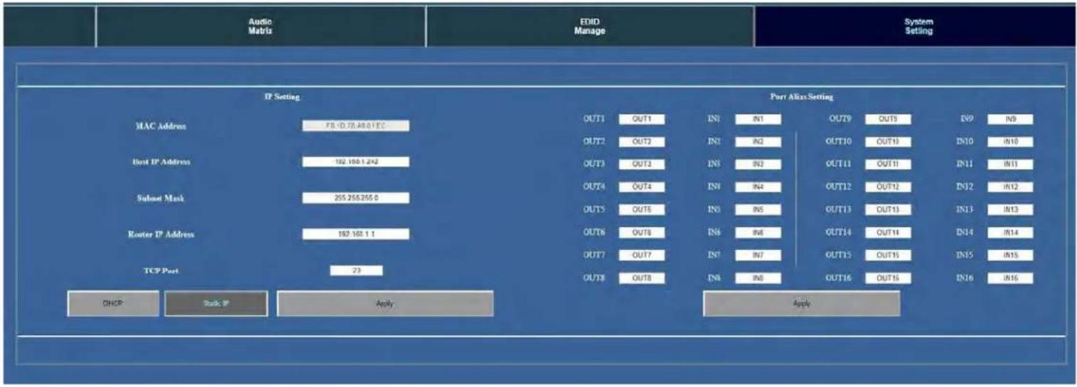
Web Interface: System Config
The System Config tab let you achieve two functions.
- Setting up your network (IP) settings
- Labeling the Inputs and Outputs for the "Sense Switch" Tab
flowchart
graph TD
    A["Audio Matrix"] --> B["IP Setting"]
    B --> C["MAC Address"]
    C --> D["Host IP Address"]
    D --> E["Subnet Mask"]
    E --> F["Router IP Address"]
    F --> G["TCP Port"]
    G --> H["DHCP"]
    G --> I["Back IP"]
    G --> J["Apply"]

    K["Port Alias Setting"] --> L["OUT1 OUT1 IN1 IN1 OUT10 OUT10 IN10 IN10"]
    K --> M["OUT2 OUT2 IN1 IN2 OUT11 OUT11 IN11 IN11"]
    K --> N["OUT3 OUT3 IN1 IN3 OUT12 OUT12 IN12 IN12"]
    K --> O["OUT4 OUT4 IN1 IN4 OUT13 OUT13 IN13 IN13"]
    K --> P["OUT5 OUT5 IN1 IN5 OUT14 OUT14 IN14 IN14"]
    K --> Q["OUT6 OUT6 IN1 IN7 OUT15 OUT15 IN15 IN15"]
    K --> R["OUT7 OUT7 IN1 IN8 OUT16 OUT16 IN16"]

    S["Apply"] --> T["Out8 OUT8 IN3 IN0 OUT16"]
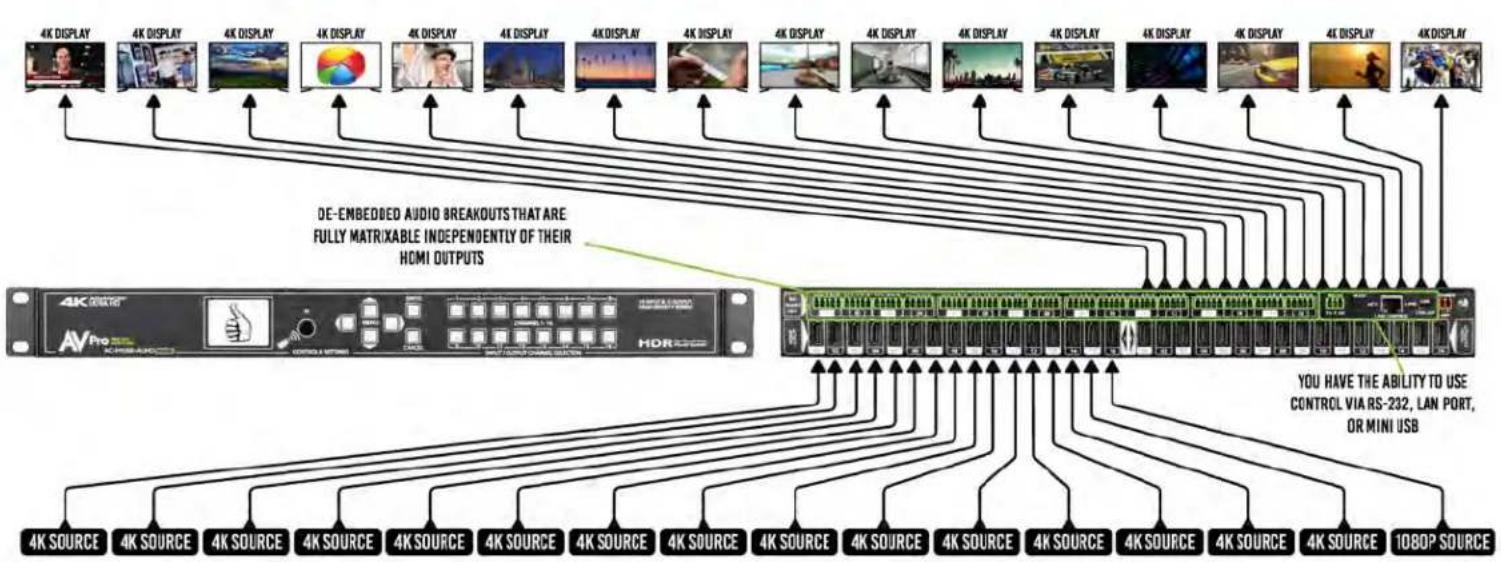
Common Usage Diagram
flowchart
graph TD
    A["4K DISPLAY"] --> B["4K DISPLAY"]
    B --> C["4K DISPLAY"]
    C --> D["4K DISPLAY"]
    D --> E["4K DISPLAY"]
    E --> F["4K DISPLAY"]
    F --> G["4K DISPLAY"]
    G --> H["4K DISPLAY"]
    H --> I["4K DISPLAY"]
    I --> J["4K DISPLAY"]
    J --> K["4K DISPLAY"]
    K --> L["4K DISPLAY"]
    L --> M["4K DISPLAY"]
    M --> N["4K DISPLAY"]
    N --> O["4K DISPLAY"]
    O --> P["4K DISPLAY"]
    P --> Q["4K DISPLAY"]
    Q --> R["4K DISPLAY"]
    R --> S["4K DISPLAY"]
    S --> T["4K DISPLAY"]
    T --> U["4K DISPLAY"]
    U --> V["4K DISPLAY"]
    V --> W["4K DISPLAY"]
    W --> X["4K DISPLAY"]
    X --> Y["4K DISPLAY"]
    Y --> Z["4K DISPLAY"]
    Z --> AA["4K DISPLAY"]
    AA --> AB["4K DISPLAY"]
    AB --> AC["4K DISPLAY"]
    AC --> AD["4K DISPLAY"]
    AD --> AE["4K DISPLAY"]
    AE --> AF["4K DISPLAY"]
    AF --> AG["4K DISPLAY"]
    AG --> AH["4K DISPLAY"]
    AH --> AI["4K DISPLAY"]
    AI --> AJ["4K DISPLAY"]
    AJ --> AK["4K DISPLAY"]
    AK --> AL["4K DISPLAY"]
    AL --> AM["4K DISPLAY"]
    AM --> AN["4K DISPLAY"]
    AN --> AO["4K DISPLAY"]
    AO --> AP["4K DISPLAY"]
    AP --> AQ["4K DISPLAY"]
    AQ --> AR["4K DISPLAY"]
    AR --> AS["4K DISPLAY"]
    AS --> AT["4K DISPLAY"]
    AT --> AU["4K DISPLAY"]
    AU --> AV["4K DISPLAY"]
    AV --> AW["4K DISPLAY"]
    AW --> AX["4K DISPLAY"]
    AX --> AY["4K DISPLAY"]
    AY --> AZ["4K DISPLAY"]
    AZ --> BA["4K DISPLAY"]
    BA --> BB["4K DISPLAY"]
    BB --> BC["4K DISPLAY"]
    BC --> BD["4K DISPLAY"]
    BD --> BE["4K DISPLAY"]
    BE --> BF["4K DISPLAY"]
    BF --> BG["4K DISPLAY"]
    BG --> BH["4K DISPLAY"]
    BH --> BI["4K DISPLAY"]
    BI --> BJ["4K DISPLAY"]
    BJ --> BK["4K DISPLAY"]
    BK --> BL["4K DISPLAY"]
    BL --> BM["4K DISPLAY"]
    BM --> BN["4K DISPLAY"]
    BN --> BO["4K DISPLAY"]
    BO --> BP["4K DISPLAY"]
    BP --> BQ["4K DISPLAY"]
    BQ --> BR["4K DISPLAY"]
    BR --> BS["4K DISPLAY"]
    BS --> BT["4K DISPLAY"]
    BT --> BU["4K DISPLAY"]
    BU --> BV["4K DISPLAY"]
    BV --> BW["4K DISPLAY"]
Maintenance & Support
To ensure reliable operation of this product as well as protecting the safety of any person using or handling this device while powered, please observe the following instructions.
- Use the power supplies provided. If an alternate supply is required, check voltage, polarity and that it has sufficient power to supply the device it is connected to.
- Do not operate these products outside the specified temperature and humidity range given in the above specifications.
- Ensure there is adequate ventilation to allow this product to operate efficiently.
- Repair of the equipment should only be carried out by qualified professionals as these products contain sensitive components that may be damaged by any mistreatment.
- Only use this product in a dry environment. Do not allow any liquids or harmful chemicals to come into contact with these products.
- Clean this unit with a soft, dry cloth. Never use alcohol, paint thinner or benzene to clean this unit.
Damage Requiring Service
The unit should be serviced by qualified service personnel if:
• The DC power supply cord or AC adaptor has been damaged
- Objects or liquids have gotten into the unit
• The unit has been exposed to rain
- The unit does not operate normally or exhibits a marked change in performance
• The unit has been dropped or the housing damaged
Support
Should you experience any problems while using this product, first, refer to the Troubleshooting section of this manual before contacting Technical Support. When calling, the following information should be provided:
• Product name and model number
• Product serial number
- Details of the issue and any conditions under which the issue is occurring
- Warranty
If your product does not work properly because of a defect in materials or workmanship, AVProEdge (referred to as “the warrantor”) will, for the length of the period indicated as below, (Parts/Labor (10) Years), which starts with the date of original purchase (“Limited Warranty period”), at its option either (a) repair your product with new or refurbished parts, or (b) replace it wit new or a refurbished product. The decision to repair or replace will be made by the warrantor. During the “Labor” Limited Warranty period there will be no charge for labor. During the “Parts” warranty period, there will be no charge for parts. You must mail-in your product during the warranty period. This Limited Warranty is extended only to the original purchaser and only covers product purchased as new. A purchase receipt or other proof of original purchase date is required for Limited Warranty service.
This warranty extends to products purchased directly from AVPro or an authorized dealer. AVPro is not liable to honor this warranty if the product has been used in any application other than that for which it was intended, has been subjected to misuse, accidental damage, modification or improper installation procedures, unauthorized repairs or is outside of the warranty period. Please direct any questions or issues you may have to your local dealer before contacting AVPro.
Thank you for choosing AVProEdge!
Please contact us with any questions, we are happily at your service!

CE


AVProEdge
2222 E 42nd St N \~ Sioux Falls, SD 57104
1-877-886-5112 \~ 605-274-6055
- Features:
- Easy to use:
- In The Box:
- Table of Contents
- Device Feature Overview:
- Basic Setup:
- Quick Setup:
- Front Panel Control
- Switching:
- Navigating the Control Screen:
- Control Screen - Switch Routing:
- Control Screen - EDID Management:
- Available EDID's:
- Control Screen - Audio Settings
- Control Screen - Network (IP) Setting
- IR Details:
- IR Remote Control:
- RS-232 and TCP/IP Commands:
- Command Example: DHCP and setting the IP Address
- Command List cont:
- Using Multiple Units In One System:
- Device Addresses When Using Serial Communication:
- Cascading with IP Control:
- Extracted Audio:
- Extracted Audio cont:
- PC Control Software - Side Bar:
- PC Control Software - Matrix Tab (OUTPUT 1-8):
- PC Control Software - Matrix Tab (OUTPUT 9-16):
- PC Control Software - EDID Tab:
- PC Control Software - IP Config Tab:
- Web Interface: Sense Switch
- Web Interface: Audio Matrix
- - Select the Ex-Audio Matrix Mode:
- Web Interface: EDID Manage
- Web Interface: System Config
- Maintenance & Support
- Damage Requiring Service
- Support
- - Warranty
Brand : AVPro Edge
Model : AC-MX1616-AUHD-GEN2
Category : Router