
IP-A1PC580R - Pregnant TOA - Free user manual and instructions
Find the device manual for free IP-A1PC580R TOA in PDF.


| Product Type | IP Ceiling Mount Speaker |
| Model | IP-A1PC580R |
| Brand | TOA |
| Power Supply | PoE (IEEE802.3af Class 3) |
| Network Interface | LAN Port (RJ45, Cat5 or greater) |
| Broadcast Modes | SIP, VMS, Multicast, Internal Sound Source |
| Control Input | 2 channels, No-voltage make contact |
| Control Output | 1 channel, Open collector output |
| Audio Input | Line/Mic input (removable terminal plug) |
| Audio Output | Line output (same as speaker output) |
| Internal Sound Sources | Up to 20 files |
| Multicast Ports | Up to 20 |
| Mounting | Ceiling mount (requires safety wire, not supplied) |
| Accessories | Pattern paper, 2x removable terminal plugs (6-pin), 4x machine screws 5x38 |
| Safety | Indoor use only; attach safety wire; do not expose to water |
| Compliance | FCC Class A |
| Default Login | Username: admin, Password: guest |
Frequently Asked Questions - IP-A1PC580R TOA
User questions about IP-A1PC580R TOA
0 question about this device. Answer the ones you know or ask your own.
Ask a new question about this device
Download the instructions for your Pregnant in PDF format for free! Find your manual IP-A1PC580R - TOA and take your electronic device back in hand. On this page are published all the documents necessary for the use of your device. IP-A1PC580R by TOA.
USER MANUAL IP-A1PC580R TOA
IP CEILING MOUNT SPEAKER
IP SQUARE SPEAKER
IP-A1PC580R
IP-A1PC580S
Thank you for purchasing TOA's IP Speaker.
Please carefully follow the instructions in this manual to ensure long, trouble-free use of your equipment.
TABLE OF CONTENTS
- SAFETY PRECAUTIONS ...... 2
- SUMMARY AND FEATURES 4
- ABOUT SECURITY MEASURES ...... 4
- DIMENSIONAL DRAWINGS .... 5
- NOMENCLATURE AND FUNCTIONS ...... 6
- SYSTEM EXAMPLE 8
6.1. SIP Broadcasting/Two-way Communication 8
6.2. VMS Broadcasting 8
- HANDLING PRECAUTIONS 8
- INSTALLATION PRECAUTIONS 9
- INSTALLATION 9
9.1. IP-A1PC580R 9
9.2.IP-A1PC580S 10
- CONNECTIONS 10
10.1. Connections to Line/Mic Input and Line Output Terminals 10
10.2. Connections to Control Input and Output Terminals 11
10.3. Removable Terminal Plug Connections 12
- SETTINGS 13
11.1. System Settings Summary 13
11.2. System Requirements 13
11.3. Connection with Browser 14
- INITIALIZATION OF SETTINGS 15
- CAUTIONS REGARDING THE AVC/H.264 PATENT LICENSE 16
- OPEN SOURCE SOFTWARE 16
- ACCESSORIES 16
1. SAFETY PRECAUTIONS
- Before installation or use, be sure to carefully read all the instructions in this section for correct and safe operation.
- Be sure to follow all the precautionary instructions in this section, which contain important warnings and/or cautions regarding safety.
• After reading, keep this manual handy for future reference.

WARNING
Indicates a potentially hazardous situation which, if mishandled, could result in death or serious personal injury.

CAUTION
Indicates a potentially hazardous situation which, if mishandled, could result in moderate or minor personal injury, and/or property damage.

WARNING
When Installing the Speaker
- Do not expose the speaker to rain or an environment where it may be splashed by water or other liquids, as doing so may result in fire or electric shock.
• Install the speaker only in a location that can structurally support the weight of the speaker and the mounting bracket. Doing otherwise may result in the speaker falling down and causing personal injury and/or property damage. - Since the speaker is designed for indoor use, do not install it outdoors. The speaker is to be connected only to PoE networks without routing to the outside plant. If installed outdoors, the aging of parts causes the speaker to fall off, resulting in personal injury. Also, when it gets wet with rain, there is a danger of electric shock.
- Do not mount the speaker in locations exposed to constant vibration. The mounting bracket can be damaged by excessive vibration, potentially causing the speaker to fall, which could result in personal injury.
When the Speaker is in Use
- Should the following irregularity be found during use, immediately cut off the power supply from a PoE switching hub and contact your nearest TOA dealer. Make no further attempt to operate the speaker in this condition as this may cause fire or electric shock.
- If you detect smoke or a strange smell coming from the unit
- If water or any metallic object gets into the speaker
- If the speaker falls, or the speaker case breaks
- If the LAN cable is damaged (exposure of the core, disconnection, etc.)
-
If the speaker suddenly stops producing sound
-
To prevent a fire or electric shock, never open nor remove the speaker case as there are high voltage components inside the speaker. Refer all servicing to qualified service personnel.
- To prevent the electromagnetic wave from badly influencing medical equipment, make sure to switch off the speaker's power when placing it in close proximity to the medical equipment.

CAUTION
When Installing the Speaker
- Attach the safety wire to the speaker. If not attached, the speaker could fall off, resulting in personal injury.
- Avoid installing the speaker in humid or dusty locations, in locations exposed to the direct sunlight, near the heaters, or in locations generating sooty smoke or steam as doing otherwise may result in fire or electric shock.
- Avoid touching the speaker's sharp metal edge to prevent injury.
When the Speaker is in Use
- Do not operate the speaker for an extended period of time with the sound distorting. Doing so may cause the speaker to heat, resulting in a fire.
- Have the speaker checked periodically by the shop from where it was purchased. Failure to do so may result in corrosion or damage to the speaker or its mounting bracket that could cause the unit to fall, possibly causing personal injury.

The IP-A1PC580R and IP-A1PC580S IP speakers are capable of delivering extremely high volume sound output. Therefore, close proximity to the speaker over time could present the danger of hearing impairment. Be sure to follow the instructions below when conducting performance tests:
- Turn down the sound volume before adjusting the volume.
- Do not position one's ear close to the speaker.
- Point the speaker in a direction where no people are present.
- Avoid listening to high-volume output for prolonged periods of time.
FCC REQUIREMENTS
Note
This equipment has been tested and found to comply with the limits for a Class A digital device, pursuant to Part 15 of the FCC Rules. These limits are designed to provide reasonable protection against harmful interference when the equipment is operated in a commercial environment. This equipment generates, uses, and can radiate radio frequency energy and, if not installed and used in accordance with the instruction manual, may cause harmful interference to radio communications.
Operation of this equipment in a residential area is likely to cause harmful interference in which case the user will be required to correct the interference at his own expense.
Modifications
Any modifications made to this device that are not approved by TOA Corporation may void the authority granted to the user by the FCC to operate this equipment.
This equipment is not suitable for use in locations where children may be present.
2. SUMMARY AND FEATURES
The IP-A1PC580R/A1PC580S IP speakers are equipped with a built-in power amplifier and sound source memory.
It can be connected to and used over a local network.
- Power is supplied by way of PoE switching hubs.
- The IP speakers are compatible with the following broadcasting modes:
| Internal sound source broadcasting mode | Enables broadcast of up to 20 internal sound source files by means of control input or Remote API (HTTP). |
| VMS broadcasting mode Enables backchannel audio broadcast from the VMS (Video management system) software using the common protocol for IP cameras. | |
| SIP broadcasting mode Enables SIP broadcasts from any voice communications device that utilizes the SIP protocol, such as SIP or IP telephone (IP-PBX) systems. | |
| Multicast broadcasting mode | Allows up to 20 multicast ports to be set up, for 20 multicast audio stream paging groups. |
- Orders of priority can be set among the various broadcasting modes, meaning higher priority broadcasts can interrupt and override lower priority broadcasts.
- Since the speaker is equipped with individual offset adjustable volumes for each broadcasting modes and patterns (internal sound source), actual broadcasting volume can be normalized or optimized.
- Broadcasts can be controlled using Remote API or control inputs from connected external equipment.
- Connected external equipment can be controlled by control outputs in synchronization with speaker broadcasts.
3. ABOUT SECURITY MEASURES
- Ensure that sufficient security measures are taken on the customer's own responsibility.
• TOA Corporation takes no responsibility for damage or loss caused by security-related problems, such as illegal access. - To help prevent illegal access to the unit, be sure to change the user ID and password from those used for initial setup. For setting methods and other details, please refer to the separate setup manual which can be downloaded from the TOA DATA Library (https://www.toa-products.com/international/).
- Take utmost care in the management of the unit's communications password.
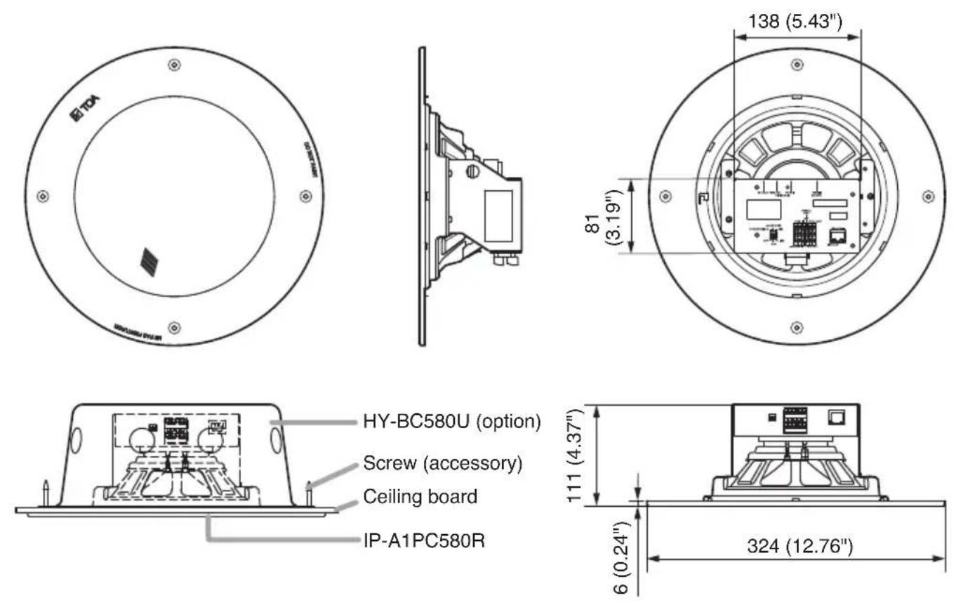
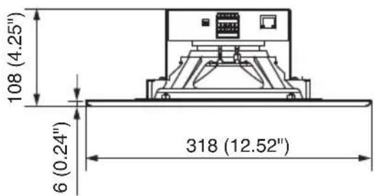
4. DIMENSIONAL DRAWINGS
Unit: mm
[IP-A1PC580R]
[IP-A1PC580S]
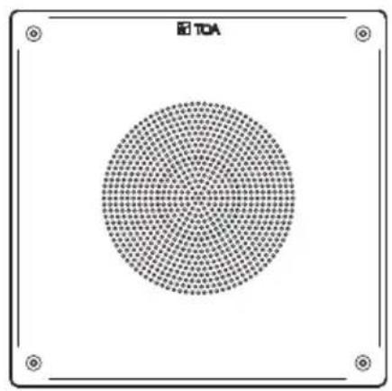
natural_image
Circular grid pattern with no text or symbols, centered on a white background (no readable text or symbols)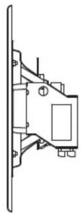
natural_image
Technical line drawing of a mechanical bracket or bracket assembly (no text or symbols)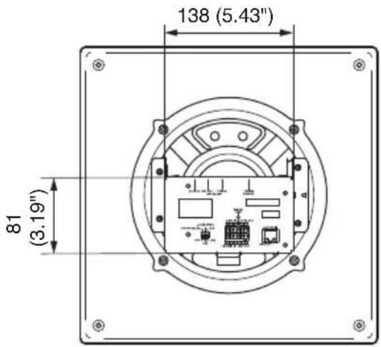
5. NOMENCLATURE AND FUNCTIONS
[IP-A1PC580R] [IP-A1PC580S]
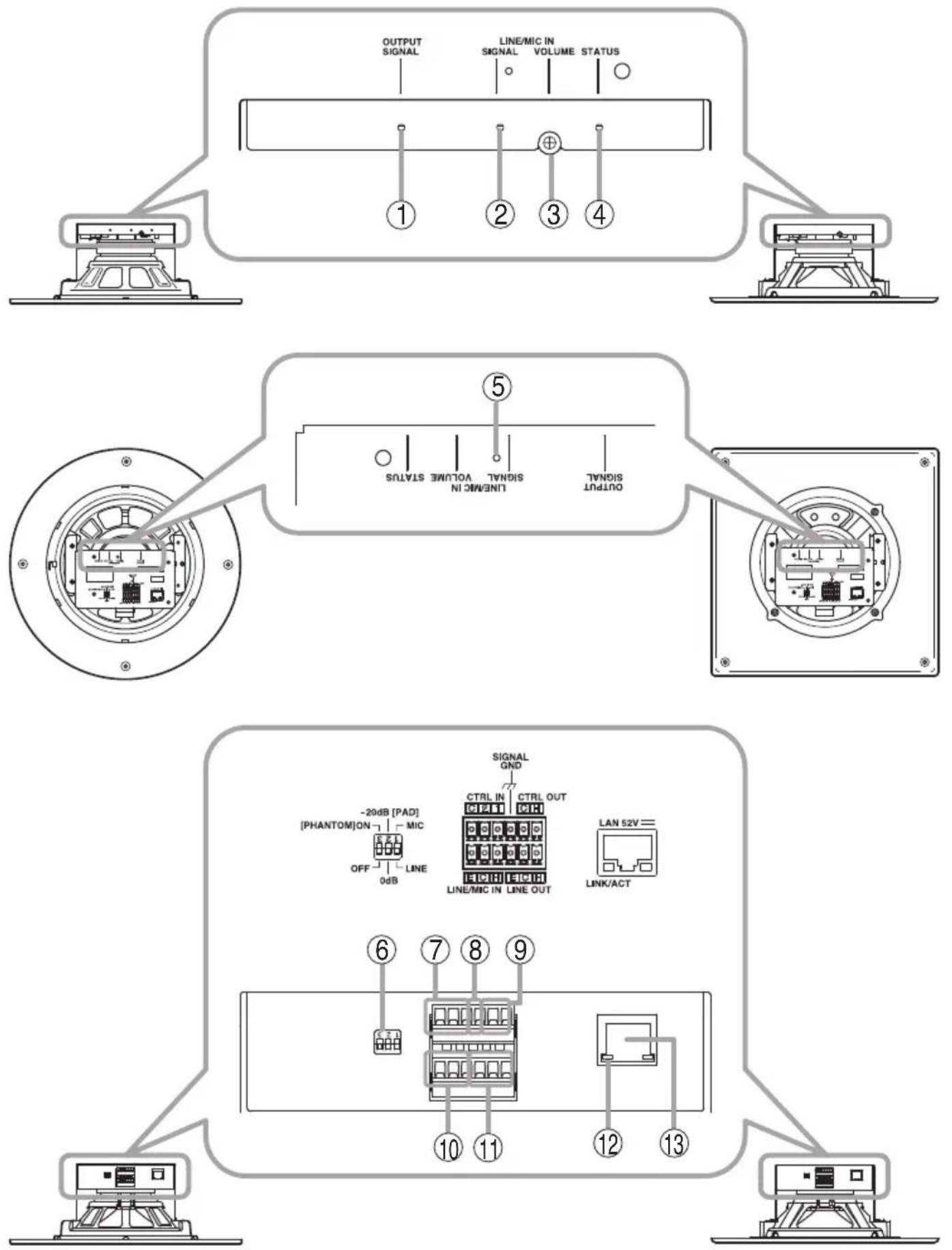
1. Line output signal indicator (green)
Lights green when a signal is outputting from this speaker or Line output.
2. Line/Mic input signal indicator (green, red)
Lights green when a signal is input to Line/Mic input. Lights red when the input signal level is too high.
3. Line/Mic input volume control
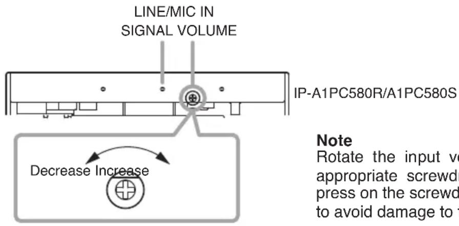
Adjusts the volume level of the Line/Mic input. Rotate this volume control clockwise to increase the volume level and counterclockwise to decrease it.
Set this volume not to make the Line/Mic input signal indicator (2) light up in red.
4. Status indicator (green, blue, yellow, red)
Indicates the speaker's operating status.
| Unit Operation Status Indicator | |
| System startup Flashing green | |
| Broadcast standby Continuously lit green | |
| Broadcasting Continuously lit blue | |
| System mute* Flashing red | |
| Initialization or firmware updating | Continuously lit yellow |
* System mute is a state in which this speaker is muted by the control from the transmitting device.
5. Reset key
The speaker begins to restart when this key is clicked.
Hold down this key until the Status indicator (4) lights yellow to initialize the speaker's settings.
6. DIP switch
• Line/Mic switch (Switch 1)
Set this switch to MIC when connecting a microphone, and to LINE when connecting a general sound source device other than a microphone.
Default setting: LINE
• PAD switch (Switch 2)
Enables or disables the microphone input pad. When the input level is high, set the PAD to -20 dB. Default setting: 0 dB
- Phantom switch (Switch 3)
Set whether or not to supply phantom power to the microphone connected to Line/Mic input terminals (10). Phantom power is a 12 V DC.
Default setting: OFF
7. Control input terminals
Allows input of control signals from connected external equipment to enable actions set in the Event settings.
8. Functional ground terminal
If excessive noise is produced when the speaker is connected to external equipment, connect this terminal to the external equipment's functional ground terminal, potentially minimizing the noise level.
Note
This terminal is not for protective ground.
9. Control output terminals
Allows control of external equipment in synchronization with the unit operation.
10. Line/Mic input terminals
Connects with a microphone or sound source device. This can be used as an audio input during SIP calls, or for monitoring VMS broadcast.
Adjust with the switches of the DIP switch according to the output level of the connected device.
11. Line output terminals
Connects with an external amplifier etc. and outputs the same audio as the speaker output.
12. LINK/ACT indicator (green)
Flashes when data is being sent or received over a network.
13. LAN port
Connect to a PoE switching hub using a LAN cable.
6. SYSTEM EXAMPLE
6.1. SIP Broadcasting/Two-way Communication
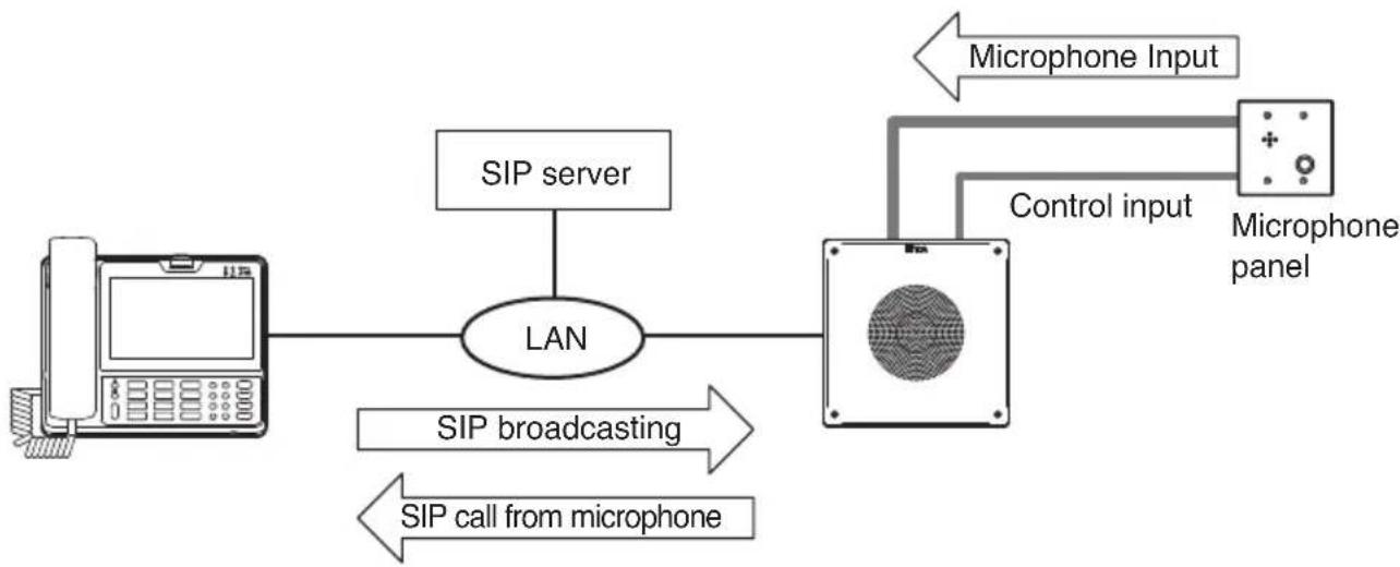
flowchart
graph TD
    A["Telephone"] --> B["LAN"]
    B --> C["Microphone panel"]
    C --> D["Control input"]
    D --> E["Microphone Input"]
    B --> F["SIP server"]
    B --> G["SIP broadcasting"]
    B --> H["SIP call from microphone"]
6.2. VMS Broadcasting
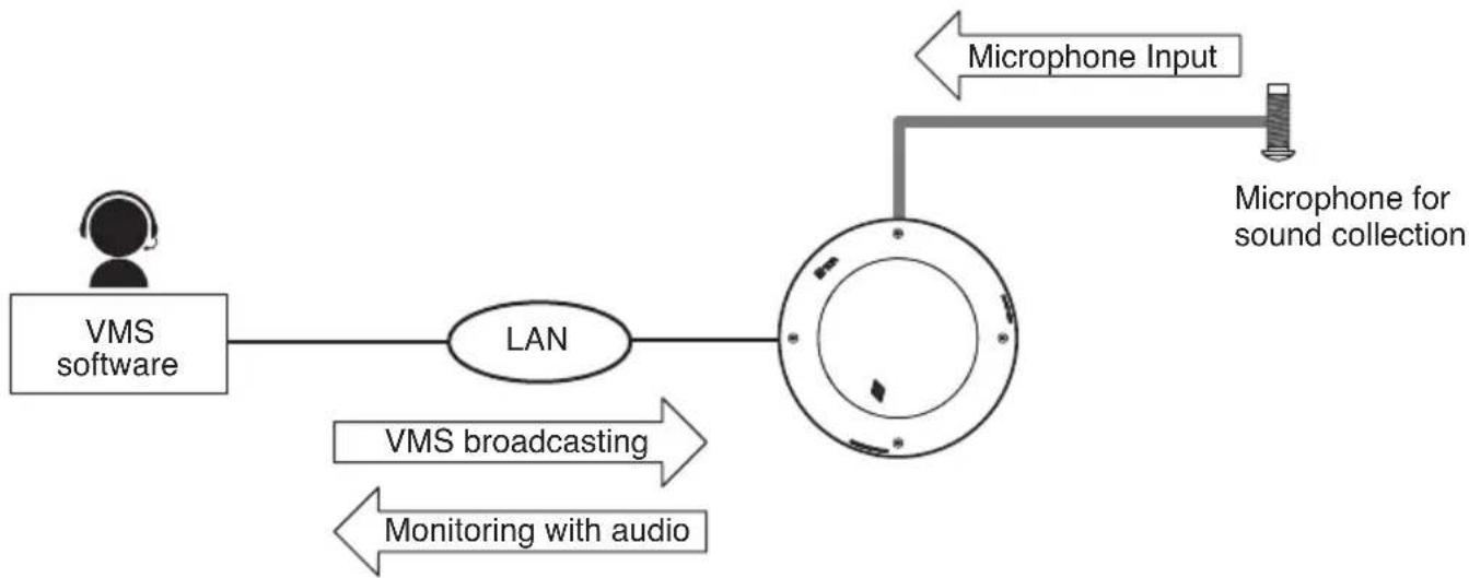
flowchart
graph LR
    A["VMS software"] --> B["LAN"]
    B --> C["Microphone for sound collection"]
    C --> D["Microphone Input"]
    B --> E["VMS broadcasting"]
    B --> F["Monitoring with audio"]
7. HANDLING PRECAUTIONS
- Please apply the latest firmware version to this product. The latest version is available at the TOA DATA Library (https://www.toa-products.com/international/).
- As this product is IP-based, a slight time lag between actual and broadcast may happen.
- Broadcast audio may sometimes break up due to packet loss or network failure.
- Periodic inspection and manual rebooting are needed to extend the product life.
- This product may reboot automatically to keep the stable operation.
8. INSTALLATION PRECAUTIONS

CAUTION
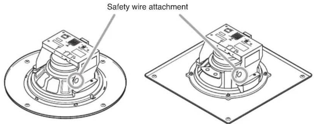
Observe the following instructions when attaching the safety wire. Failure to do so could result in the speaker falling, potentially resulting in personal injury.
- Select a safety wire that is strong enough to withstand the total weight of the unit being mounted.
- Use a wire with a diameter larger than 1.5 mm or 0.06".
- Attach the safety wire so that it does not become slack.
Notes
- Since the safety wire is not supplied with the IP speaker, be sure to prepare it separately.
- When attaching the safety wire, be sure that it is fastened securely to the safety wire attachment ring.
9. INSTALLATION
9.1. IP-A1PC580R
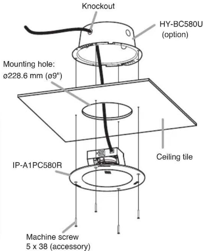
Use back can HY-BC580U if UL 2043 (use in air handling spaces) is required.
All wire entry knockouts should use metal conduit and metal fitting only. No rubber bushings on back can.
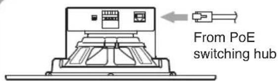
Connect the IP speaker to the PoE Switching hub using a LAN cable (straight UTP or STP cable, both rated at Category 5 or greater and fitted with RJ45 connectors).
Compatible switching hubs: Switching hubs conforming to PoE (IEEE802.3 af Class 3) specifications.
9.2. IP-A1PC580S
Note
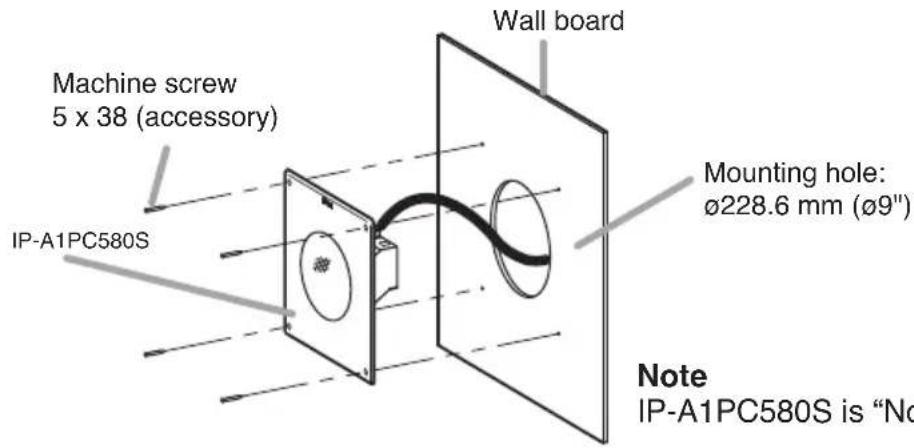
IP-A1PC580S is "Not for use in air handling spaces."
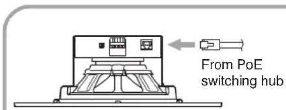
Connect the IP speaker to the PoE Switching hub using a LAN cable (straight UTP or STP cable, both rated at Category 5 or greater and fitted with RJ45 connectors).
Compatible switching hubs:
Switching hubs conforming to PoE (IEEE802.3 af Class 3) specifications.
10. CONNECTIONS
10.1. Connections to Line/Mic Input and Line Output Terminals
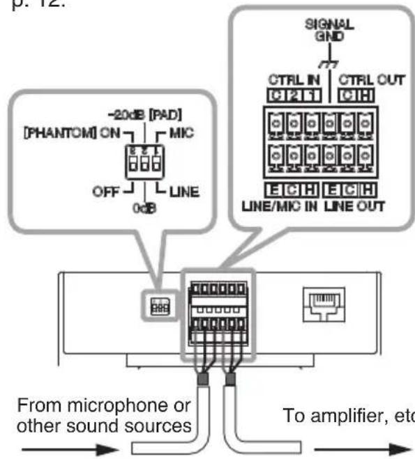
Use the supplied removable terminal plugs (6 pins) for connection. Use a 2-core shielded cable to connect the audio device. Also, set the DIP switches according to the audio device to be connected. For connection of the removable terminal plugs, see "Removable Terminal Plug Connections" on p. 12.
flowchart
graph TD
    A["From microphone or other sound sources"] --> B["Microcontroller"]
    B --> C["Signal GND"]
    C --> D["CTRL IN"]
    C --> E["CTRL OUT"]
    B --> F["Line/MIC IN"]
    B --> G["Line OUT"]
    B --> H["OFF"]
    B --> I["MINIC"]
    B --> J["-20dB PAD"]
    B --> K["PHANTOM ON"]
[DIP switch settings]
| Input device DIP switch settings | ||
| Line level sound source | 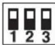 | 1: LINE2: 0 dB [PAD]3: OFF [PHANTOM](Default settings) |
| Dynamic microphone | 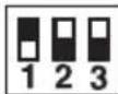 | 1: MIC2: 0 dB [PAD]3: OFF [PHANTOM] |
| Electret condenser microphone | 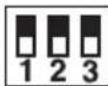 | 1: MIC2: -20 dB [PAD]3: ON [PHANTOM] |
Tip
Change the DIP switch settings while the power is off.
When the connected unit has an unbalanced input, make the connections as follows:

[LINE/MIC IN level adjustment]
Set roughly the volume of individual connected devices by DIP switch.
After that, use the Line/Mic input volume control for fine volume adjustments. Adjust the level so that the Line/Mic signal indicator lights green, not red.
Note
Rotate the input volume control screw using an appropriate screwdriver. When rotating, do not press on the screwdriver with too much force, so as to avoid damage to the adjuster.
10.2. Connections to Control Input and Output Terminals
Use the supplied removable terminal plugs (6 pins) for connection.
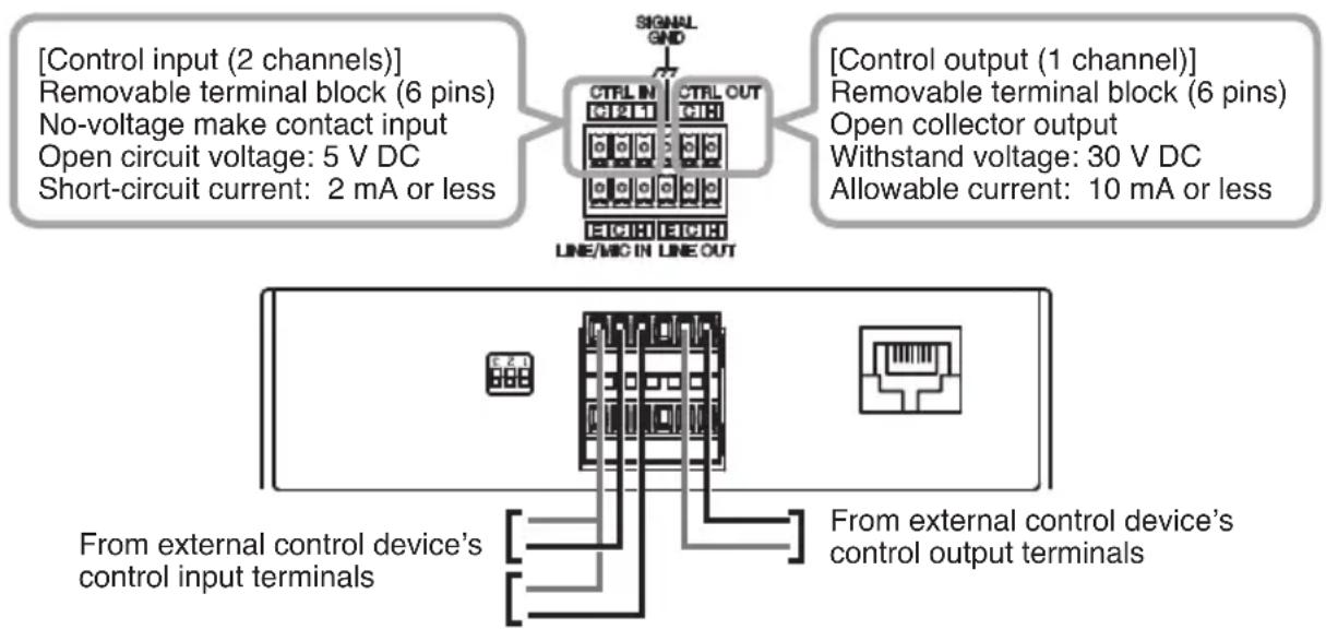
Connect a control line of 2 channels control input and 1 channel control output from the external control device to the IP speaker control input or control output terminal.
For connection of the removable terminal plugs, see “Removable Terminal Plug Connections” on p. 12.
The following functions can be assigned to the control input and control output terminals by browser settings:
| Assignable Functions | |
| Control Input terminals | • SIP device calls• Internal sound source broadcasting• Change the broadcasting volume (Mute or Offset) |
| Control Output terminals | • SIP broadcast in progress output• VMS broadcast in progress output• Multicast broadcast in progress output• Internal sound source broadcast in progress output |
flowchart
graph TD
    A["Signal GND"] --> B["CTRL IN CTRL OUT"]
    B --> C["Line/MIC IN LINE OUT"]
    D["Control input (2 channels)"] --> E["Removable terminal block (6 pins)"]
    E --> F["No-voltage make contact input"]
    F --> G["Open circuit voltage: 5 V DC"]
    G --> H["Short-circuit current: 2 mA or less"]
    I["Control output (1 channel)"] --> J["Removable terminal block (6 pins)"]
    J --> K["Open collector output"]
    K --> L["Withstand voltage: 30 V DC"]
    L --> M["Allowable current: 10 mA or less"]
    N["From external control device's control input terminals"] --> O["External Control Device"]
    P["From external control device's control output terminals"] --> Q["External Control Device"]
For settings, please refer to the separate setup manual. The latest version of the setup manual is available on the TOA DATA Library (https://www.toa-products.com/international/).
10.3. Removable Terminal Plug Connections
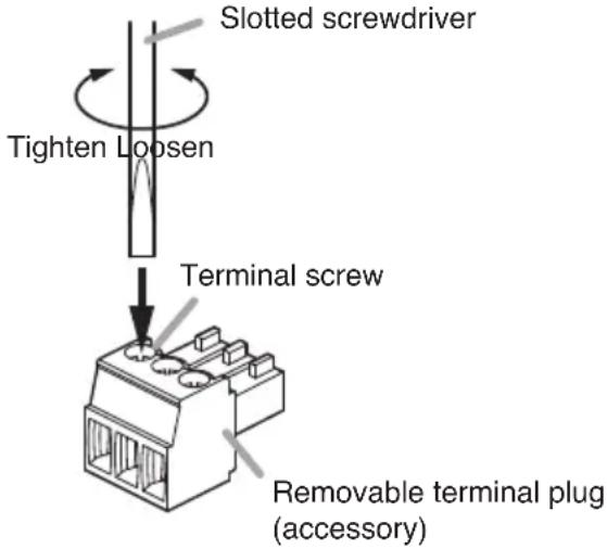
Please note the following points when making connections to the control input or output terminals using the supplied removable terminal plugs:
- Do not tin stripped wire ends with solder. Soldered wire ends will be crushed when the terminal plug screws are tightened, leading to higher contact resistance and potentially resulting in an abnormal rise in the temperature of the connected parts.
- Use AWG 28 – 22 wire ( 0.32 - 0.64 mm solid wire or multi-stranded wire with a cross-sectional area of 0.08 - 0.32 mm^2 ).
- Strip the wire end back about 7 mm (0.28").
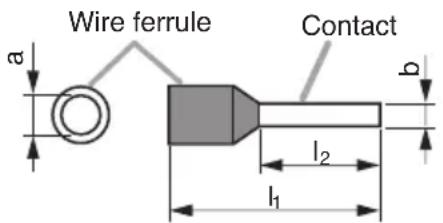
- When connecting 2 wires or a signal cable to a single terminal, crimp them in an insulated (twin) wire ferrule to prevent their core wires from being separated from one another. Use a ferrule of the dimensions shown in the figure as below.
Note
b: 0.8–1.1 mm (0.03" – 0.04")
l2: 8 mm (0.31")
Select dimensions “a” and “l1” depending on the wires to be used.
11. SETTINGS
11.1. System Settings Summary
The following settings can be performed using a PC browser connected to the same network as the IP speaker.
| Setting Name Setting Item | |
| Status Confirmation of current firmware version, network settings, volume setting | |
| Network Network settings such as IP address | |
| SIP Settings of SIP | connection enable/disable, SIP server address, authentication information, and audio codec |
| VMS Broadcasting Settings of VMS connection enable/disable and authentication information, connection port settings | |
| Multicast | Settings of multicast reception enable/disable, multicast address and port, and control output during multicast broadcast |
| Audio Settings of speaker volume and input volume for individual broadcast classifications | |
| Media | Uploading/downloading or deletion of sound source files such as messages to or from the internal memory |
| Pattern | Registration of sound source playback to be associated with events as patterns |
| Event | Settings of operations to be synchronized with the control input and control output |
| Priority | Settings of priority order for each broadcast mode; SIP broadcast, VMS broadcast, multicast broadcast and internal sound source broadcast |
| User | Changing username and password |
| Maintenance | Download and upload the configuration file, initialization, firmware update, hardware reboot and downloading action logs |
| System | Date and time settings, NTP server settings, time zone settings |
For more information, please refer to the separate setup manual.
The latest version of the setup manual is available on the TOA DATA Library. (https://www.toa-products.com/international/)
11.2. System Requirements
Connectable system requirements are as follows:
| Display | Resolution: 1366 × 768 or greater |
| OS | Windows 10 Pro (64-bit), Windows 10 Home (64-bit), Windows 11 Pro, Windows 11 Home |
| Browser Microsoft Edge, Google Chrome | |
Notes
- Windows and Microsoft Edge are registered trademarks of Microsoft Corporation of the United States in the United States and other countries.
- Google Chrome is a trademark of Google LLC of the United States in the United States and other countries.
11.3. Connection with Browser
11.3.1. Connection presets
The IP speaker is factory-preset as follows:
Username: admin
Password: guest
IP address: 192.168.14.1
Subnet mask: 255.255.255.0
Default gateway: 0.0.0.0
Before connecting a PC to the IP speaker and changing its setting, it will be necessary to set the PC's network settings so that it can operate on the same network as the IP speaker. Take care that no IP addresses are duplicated in the same network. For example, if the IP speaker's IP address is 192.168.14.1, set the PC's IP address to 192.168.14.10.
11.3.2. Making connection
Notes
- Avoid simultaneously connecting to the IP speaker from multiple PCs.
- Avoid simultaneously connecting to the IP speaker from a single PC using multiple browsers.
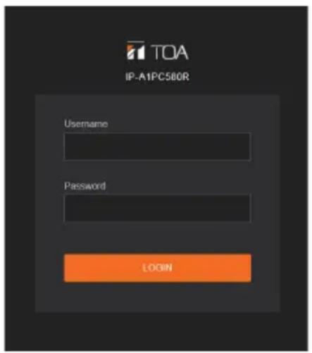
Step 1. Start the browser and enter the speaker's IP address in the address field. The Login screen is displayed.
Step 2. Enter the username and password, and click the LOGIN button.
The Status screen is displayed, enabling a range of settings.
Note
For details regarding the setting method, please refer to the separate setup manual. The latest version of the setup manual is available on the TOA DATA Library. (https://www.toa-products.com/international/)
12. INITIALIZATION OF SETTINGS
Follow the procedure below to return all IP speaker settings to their default:
Tip
When initialized with the Reset key, the IP speaker's sound source files are left in "Media", not deleted. Initialization to factory defaults, including deletion of sound source files, should be performed using the browser settings menu.
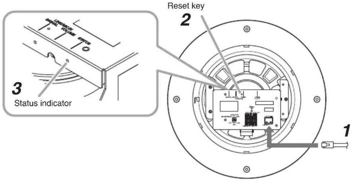
Step 1. Connect he unit to the PoE switching hub using a LAN cable. The IP speaker will be started.
Step 2. Hold down the Reset key located on the top panel using a pointed tool. The IP speaker automatically restarts and settings initialization begins.
Tip
Clicking on the Reset key causes the IP speaker to be restarted.
If pressure on the Reset key is released part way through the initialization process, only unit restart will be performed, and the settings will not be initialized.
To click on the Reset key, use a tool that is thinner than 1.5mm (0.06") and longer than 5mm (0.2").
Step 3. When the status indicator lights yellow, release the reset key.
When initialization is complete, the status indicator lights green and all settings will be initialized to their default settings.
[Default Settings]
Username: admin
Password: guest
IP address: 192.168.14.1
Subnet mask: 255.255.255.0
Default gateway: 0.0.0.0
13. CAUTIONS REGARDING THE AVC/H.264 PATENT LICENSE
TOA's IP-A1PC580R/A1PC580S IP speakers employ MPEG technology (AVC/H.264 Standard) regarding the handling of image information. TOA Corporation has received approval to use this technology from MPEG LA, LLC, the patent management group.
Please note that the use of this product is prohibited except the following cases:
The use of the product is intended for personal use of a user of the MPEG technology and also for nonprofit use, which includes (i) video encoding conforming to the AVC/H.264 Standard (hereinafter referred to as “AVC/H.264”) and/or (ii) personal use and decoding of AVC/H.264 encoded by an MPEG technology user engaged in non-profit activities and/or AVC/H.264 furnished by a video provider who is granted a license by MPEG LA, LLC.
Regarding use for sales promotion or commercial purposes, or additional licensing information, please contact MPEG LA, LLC (https://www.mpegla.com).
14. OPEN SOURCE SOFTWARE
This product uses software based on open source software license(s).
If you need further information about the original open source software including source code, please download it from the TOA DATA Library (https://www.toa-products.com/international/).
Please note that we cannot answer any questions about the contents of the original source code.
This product includes software developed by the OpenSSL Project for use in the OpenSSL Toolkit (http://www.openssl.org/).
This product includes cryptographic software written by Eric Young (eay@cryptsoft.com).
15. ACCESSORIES
Pattern paper 1
Removable terminal plug (6 pins) 2
Machine screw 5 x 38 4
Tip
The specifications of this product are available in TOA DATA Library (https://www.toa-products.com/international/).
Scan the QR Code at right with your mobile phone camera to access the WEB site and search for this product number (IP-A1PC580R or IP-A1PC580S).
Note: "QR Code" is a registered trademark of DENSO WAVE INCORPORATED.

Traceability Information for USA
Manufacturer:
TOA Corporation
7-2-1, Minatojima-Nakamachi, Chuo-ku, Kobe, Hyogo, Japan
Authorized representative:
TOA Electronics, Inc.
1 Harmon Plaza, Suite 700 Secaucus, New Jersey 07094, USA
- IP CEILING MOUNT SPEAKER
- IP SQUARE SPEAKER
- IP-A1PC580R
- IP-A1PC580S
- TABLE OF CONTENTS
- SAFETY PRECAUTIONS
- WARNING
- CAUTION
- When Installing the Speaker
- When the Speaker is in Use
- FCC REQUIREMENTS
- Note
- Modifications
- SUMMARY AND FEATURES
- ABOUT SECURITY MEASURES
- DIMENSIONAL DRAWINGS
- NOMENCLATURE AND FUNCTIONS
- Line output signal indicator (green)
- Line/Mic input signal indicator (green, red)
- Line/Mic input volume control
- Status indicator (green, blue, yellow, red)
- Reset key
- DIP switch
- • Line/Mic switch (Switch 1)
- • PAD switch (Switch 2)
- - Phantom switch (Switch 3)
- Control input terminals
- Functional ground terminal
- Control output terminals
- Line/Mic input terminals
- Line output terminals
- LINK/ACT indicator (green)
- LAN port
- SYSTEM EXAMPLE
- SIP Broadcasting/Two-way Communication
- VMS Broadcasting
- HANDLING PRECAUTIONS
- INSTALLATION PRECAUTIONS
- Notes
- INSTALLATION
- IP-A1PC580R
- IP-A1PC580S
- CONNECTIONS
- Connections to Line/Mic Input and Line Output Terminals
- Tip
- [LINE/MIC IN level adjustment]
- Connections to Control Input and Output Terminals
- Removable Terminal Plug Connections
- SETTINGS
- System Settings Summary
- System Requirements
- Connection with Browser
- Connection presets
- Making connection
- INITIALIZATION OF SETTINGS
- CAUTIONS REGARDING THE AVC/H.264 PATENT LICENSE
- OPEN SOURCE SOFTWARE
- ACCESSORIES
- Traceability Information for USA
Brand : TOA
Model : IP-A1PC580R
Category : Pregnant