
ChannelStrip - Audio software Metric Halo - Free user manual and instructions
Find the device manual for free ChannelStrip Metric Halo in PDF.


| Type | Audio plug-in (AU, VST2, VST3, AAX) |
| Version | 4.0.2 |
| Compatibility | 64-bit hosts; macOS 10.9+, Windows 10+ |
| License | PACE iLok (computer, iLok Cloud, 2nd/3rd gen USB key) |
| Processing Blocks | Gate/Expander, Compressor, 6-Band Parametric EQ, Delay (0-255 samples), Limiter |
| Sidechain | Filtered sidechain for Gate and Compressor (6 filter types) |
| Compressor Modes | Smooth, Warm, Fast, MIO (adjustable knee) |
| EQ Band Types | Peaking, Low Shelf, High Shelf, High Cut, Low Cut, Bandpass |
| Metering | SpectraFoo: Input RMS/Peak/PPM, Gain Reduction, Output Peak/RMS/VU, Spectragraph |
| Preset Management | Factory and user presets, A/B snapshots with blend, undo/redo, compare |
| UI Customization | Resizable, knobs styles, colors, background modes, graphs visibility |
| Signal Flow | Configurable: Compressor pre or post EQ |
| Input Controls | Phase invert, input gain (±24 dB) |
| Output Controls | Master fader (±10 dB), limiter threshold (0 to -12 dB) |
| Documentation | Free PDF user manual (63 pages) |
| Maintenance | Automatic update notification via plug-in header |
| Support | Email: support@mhsecure.com, Phone: (727) 725-9555 |
| Manufacturer | Metric Halo |
| Year | 2024 |
Frequently Asked Questions - ChannelStrip Metric Halo
User questions about ChannelStrip Metric Halo
0 question about this device. Answer the ones you know or ask your own.
Ask a new question about this device
Download the instructions for your Audio software in PDF format for free! Find your manual ChannelStrip - Metric Halo and take your electronic device back in hand. On this page are published all the documents necessary for the use of your device. ChannelStrip by Metric Halo.
USER MANUAL ChannelStrip Metric Halo
METRIC HALO
ChannelStrip 4 User's Guide
MH ChannelStrip 4 Users Guide
Metric Halo
Revision: 4.0.2
Publication date April 22, 2024
Copyright © 2024 Metric Halo. MH Production Bundle, MH ChannelStrip, MH Character, MH Dirty Delay, MH HaloVerb, MH Multiband Dynamics, MH Multiband Expander, MH Precision DeEsser, MH Sonic EQ, MH SuperGate and MH TransientControl are our trademarks. All other trademarks are the property of their respective owners.
Table of Contents
- ChannelStrip Overview 7
- System Requirements 8
- Installation 9
Mac 9
Windows 17
Update Notification (all platforms) 23
- Plug-In Header Bars 24
Plug-In Header: Top Row 25
Metric Halo Header Icon 25
Plug-in Snapshot Registers: A/B 31
Snapshot Blend 32
Plug-in Undo/Redo 33
Help Button 33
Graph Visible Selector 33
UI Size Selector 33
Compare Button 34
Soft Bypass 34
Plug-In Header: Preset Row 35
Plug-in Hamburger menu 35
Preset Step-Through Buttons 36
Preset Name/selector menu: 36
- Operation 37
Control Knob 37
Toggle Button 38
Fader 38
Filter Type 39
Sidechain Routing Switch 40
Sidechain Listen Button 40
Compressor Character 40
Input Meters 41
Gain Reduction Meter 42
Peak, RMS, VU Output Meter with Peak Hold 42
EQ Transfer Function 44
Transfer Function options 45
Spectragraph Analyzer 46
Dynamics Knee 47
- Processing 48
A Detailed Description 48
Input Conditioning 49
Gate/Expander 49
Theory Of Operation 49
Gate Enable 50
Threshold Control 50
Attack Control 50
Release Control 50
Using The Sidechain Key Input w/Selectable Filter 50
Sidechain Listen Button 50
Sidechain Routing Button 50
Sidechain Filter Enable 50
Filter Type Button 51
Filter Band Boost/Cut Control 51
Filter Band Frequency 51
Filter Bandwidth 51
Compressor 52
Theory Of Operation 52
Audio Dynamics 53
Compressor Enable 53
Post EQ 53
Auto Gain 53
Compressor Knee Control 54
Manual Make-Up Gain 55
Compressor Character 55
Threshold Control 55
Ratio Control 55
Attack Control 55
Release Control 56
Using The Sidechain Key Input w/Selectable Filter 56
Sidechain Listen Button 56
Sidechain Routing Button 56
Sidechain Filter Enable 56
Filter Type Button 56
Filter Band Boost/Cut Control 56
Filter Band Frequency 56
Filter Bandwidth 57
Equalizer 58
Theory Of Operation 58
Master Enable Button 59
Filter Type Button 59
Filter Band Color Swatch 60
Filter Enable Button 60
Filter Band Boost/Cut Control 60
Filter Band Frequency 60
Filter Bandwidth 60
Controlling The EQ With The Transfer Function 60
Master Gain 60
Delay Section 61
Limiter 61
A. Key Commands 62
B. Service and Support 63
List of Figures
3.1. MH Production Bundle Installer 17
3.2. Welcome Dialog 17
3.3. License Agreement 18
3.4.Custom Setup 19
3.5. Ready to Install 20
3.6. Final installer verification and permission to execute 21
3.7. Installation in Progress 22
3.8. Installation Complete 23
3.9. Plug-in Update Alert 23
4.1. MH Plug-in header (default setting: eq and dynamics graph display closed) 24
4.2. Preferences tab (example shown is SuperGate with sidechain filter graph closed) 25
4.3. Plug-in control pane tabs 25
4.4. standard plug-in UI Preferences 26
4.5. About tab (ChannelStrip shown) 28
4.6. Current Release Notes example 29
4.7. Update tab with new version release notes header(text from update release notes omitted from above for brevity) 30
4.8. Plug-in Header: Snapshot Registers: A/B 31
4.9. Plug-in Header: Snapshot Blend 32
4.10. Plug-in Header: Undo/Redo 33
4.11.Help Button 33
4.12. Graphs Closed 33
4.13. Graphs Open 33
4.14. UI Size Selector 33
4.15. Compare Button (inactive) 34
4.16. Compare Button (active) 34
4.17. Soft Bypass Button (not bypassed - plug-in is processing) 34
4.18. Soft Bypass Button (bypassed - plug-in is not processing) 34
4.19.MIOConsole3d ChannelStrip header 34
4.20.Preset Step-Through Buttons 36
4.21. Plug-in Header: Preset selector menu (ChannelStrip shown) 36
4.22. Preset selector menu: Audition on select 36
5.1. Swept Knob 37
5.2. Plus/Minus Knob 37
5.3. Spread Knob 37
5.4. Limiter Knob 37
5.5. Toggle Buttons 38
5.6. Master Fader 38
5.7.Peaking/Parametric 39
5.8.Low Shelf 39
5.9. High Shelf 39
5.10. High Cut 39
5.11.Low Cut 39
5.12.Bandpass 39
5.13.Sidechain Routing Switch 40
5.14. Compressor Character Switch 40
5.15. Gate/Expander Peak Meter 41
5.16. Compressor Peak Meter 41
5.17. Gain Reduction Meter 42
5.18. Output Meter (mono / enlarged) 42
5.19.EQ Transfer Function 44
5.20. Spectragraph Display 46
5.21. Dynamics Knee 47
6.1. Signal Flow: Compressor is Pre-EQ 48
6.2. Signal Flow: Compressor is Post-EQ 48
6.3. Gate/Expander 49
6.4. Compressor 52
6.5. Knee Control at 0 54
6.6. Knee Control at 1 54
6.7. Knee Control at -0.5 54
6.8.EQ Section 58
6.9.Peaking/Parametric 59
6.10. Low Shelf 59
6.11. High Shelf 59
6.12. High Cut 59
6.13.Low Cut 59
6.14.Bandpass 59
6.15.Delay 61
6.16. Limiter 61
1. ChannelStrip Overview
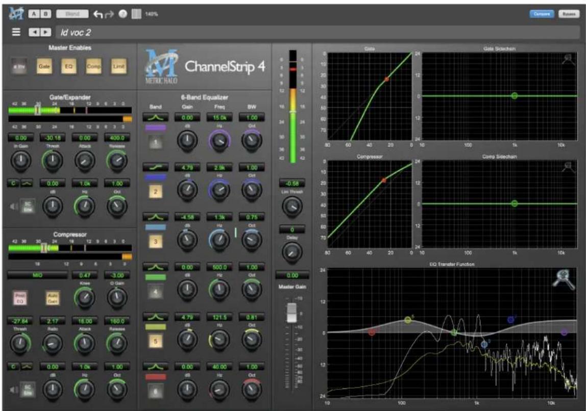
ChannelStrip is a plug-in for digital audio workstations which provides the essential basic channel processing found in the channel strip of a modern mixing console.
Processing functions include:
- Input level control
- Phase Invert
- Expander/Gate with filtered sidechain
- Compressor with filtered sidechain
• 6 band Parametric EQ - Channel delay
- Limiter
ChannelStrip 4 has several notable new features:
- MH Logo Details view
- New look, including skin choice and preferences
- Software update tracking
- Quick Links to product pages, manuals, and tech support
- Undo/Redo
• A/B snapshots, and snapshot Blend - More flexible resizability
- Common controls in the header bar (Help, Resize, Pane Disclosure)
- Enhanced multi-function Spectrafoo dynamics processor and output level metering
2. System Requirements
Hosts:
- Pro Tools™ (Mac): Pro Tools 11 or higher running on a Macintosh computer. The v4 software currently supports Native AAX operation only.
- Pro Tools™ (Windows): Pro Tools 10 or higher running on a Windows computer. The v4 software currently supports Native AAX operation only.
- Native (Mac): Any Intel or Apple Silicon-native Mac DAW (64-bit) that supports AU, VST2, VST3 or AAX plug-ins.
- Native (Windows): Any Intel Windows (64-bit) DAW that supports VST2, VST3 or AAX plug-ins.
Please Note: All v4 plug-ins are 64-bit (as were v3). If you have a need to work with an old 32-bit host, please contact MH Support and ask for the 32-bit Production Bundle v2 installer.
Operating System:
• Mac: Any Apple Silicon (ARM) or Intel-based Mac running Mac OS X 10.9 or newer
- Windows: Any Intel-based Windows PC running Windows 10 or newer.
Licensing:
- A PACE iLok.com account. You can authorize your v4 license to your computer, iLok Cloud or any 2nd or 3rd generation iLok USB key.
The first generation blue-green iLok USB keys are no longer supported by PACE for new product authorizations.
Please note that prior v2 and v3 licenses are separate and remain valid: you do not have to trade in your old iLok license. Production Bundle v3 and earlier plug-ins will continue to serve on older systems in addition to the v4 installations on newer platforms, with full preset compatibility between v3 and v4.
- One license authorizes the software on any platform.
- The most recent iLok License Manager installer can be found here: iLok License Manager application and driver installers.
Older operating systems may require a specific version of the iLok driver, which can be found here: Legacy iLok application and driver installers.
3. Installation
For both Mac and Windows, there is a single standard installer for the Production Bundle that allows you to decide which plug-ins to install to your computer, depending on what individual plug-in licenses you own and what formats you use.
IMPORTANT: Please make sure you have your license installed and available before you first launch your host after running the installer. Otherwise, you will receive a message on launch that the software is not licensed, asking you to "Buy" or "Quit". There are some hosts that will not rescan for your plug-ins on the next launch after the license is installed, and some hosts do not provide a user menu preference to rescan.
Mac
Please note— The following graphics show installation on a macOS 12 system; the process may be slightly different in other versions of the OS, but the basic concepts are the same. Small details such as file sizes shown may vary with subsequent releases.
- Double-click the "MH Production Bundle.pkg" application

MHProductionBundleInstaller_v4.0.2.157.pkg
- The first window requests permission for the installer program to scan for the presence of earlier versions of Metric Halo plug-ins. Clicking "Cancel" will quit the installer. Click "Allow" to proceed:

Click "Allow" to proceed...
- The installer dialog will appear, detailing the plug-in formats and system requirements to be installed:

Click "Continue"...
- Now you will see the Metric Halo License Agreement:
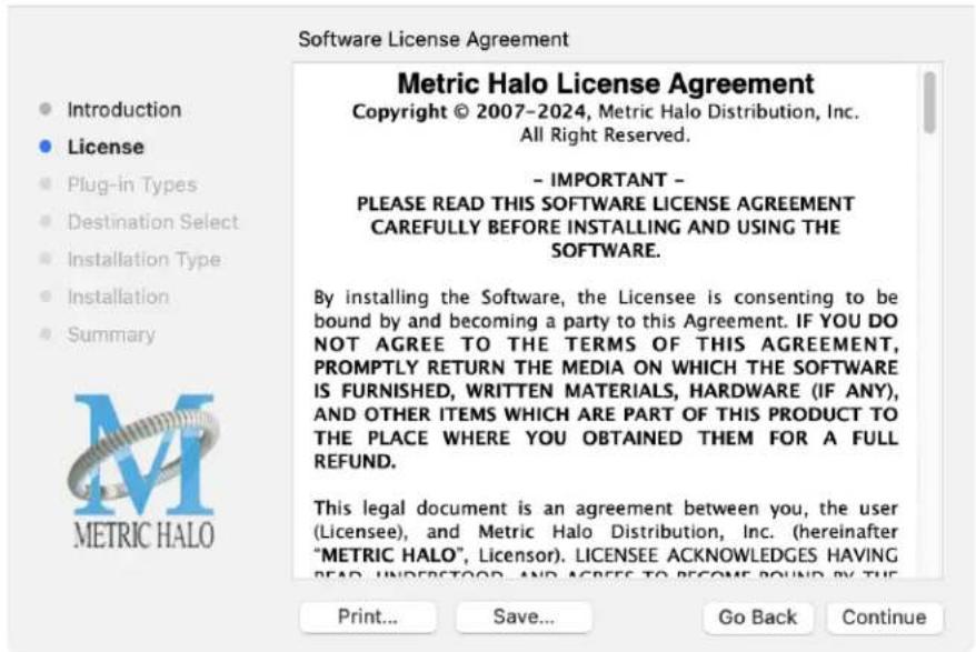
After you have read it, click "Continue"...
- Next, click "Agree" to accept the License Agreement:

- The Choose Plug-in Types selector window defaults to no plug-ins selected, so that you may choose just the plug-in formats you wish to install. Checking All Plug-In Types will install Audio Unit, VST2, VST3 and AAX plug-ins to their respective folders in the root Library directory:
• AU to /Library/Audio/Plug-Ins/Components
• VST 2 to /Library/Audio/Plug-Ins/VST
• VST 3 to /Library/Audio/Plug-Ins/VST3
- AAX to /Library/Application Support/Avid/Audio/Plug-Ins
Selecting any one or more specific plug-in types will install or upgrade only those formats, leaving older plug-ins in unselected format types untouched.
Your plug-in format selection will be saved as a preference and pre-set automatically for future Metric Halo family plug-in installations on this computer. Of course you may change your selections at that time.
Choose Plug-in Types to Install
Introduction
License
Plug-in Types
Destination Select
Installation Type
- Installation
Summary
METRIC HALO
The plug-ins are available for AAX (Pro Tools), AU (Audio Units), VST 2, and VST 3. Please select the plugin types you wish to install below:
All Plug-In types
AAX
AU
VST 3
VST 2
Go Back
Continue
- Important note for Pro Tools users
Version 4 of the AAX plugins will install alongside v3, so both will remain available in your system. There are two reasons for this:
- The v4 plug-ins are currently Native only and do not provide DSP executables for HDX/Carbon DSP chips.
- At the request of many Pro Tools users, we have made changes to the AAX v4 plug-ins to provide finer and more consistent behavior of EQ parameters when controlled by EuCon control surfaces and Pro Tools automation.
In some specific workflow cases, these changes have the potential to affect automation playback of older sessions, so the safe route would be to keep older automated sessions running on v3, and using v4 for new sessions.
For specifics on these changes, please see the latest release notes within the v4 plug-in UI by clicking on the Metric Halo logo in the upper left corner of the plug-in window.
Existing sessions will recall with the v3 instances for both Native/DSP, and you can continue to add new instances of the v3 plugins (for example, if you want to be able to use DSP versions for tracking).
You can add v4 instances as you wish to take advantage of the new features and new plug-ins.
You can switch v3 instances to v4, and your settings will be preserved.
If you load sessions with v3 instances, but only have v4 installed, Pro Tools will automatically migrate the instances to v4 Native with the parameter settings intact.
- "Select a Destination" lets you install the plugs for all users (if you are logged in as an admin), only your user, or to another volume entirely.

We recommend that you use the standard installation location unless you have a specific reason not to.
- The "Custom Install" selector window defaults to no plug-ins selected, so that you may choose exactly the plug-ins you wish to install.
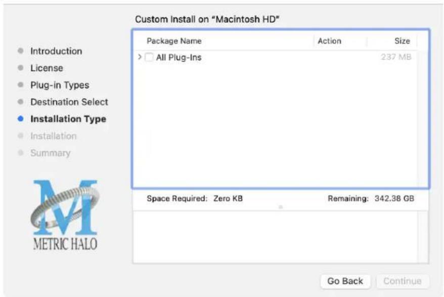

Clicking the disclosure triangle opens the selection list of the individual plug-ins. Make your selections and click "Continue" to proceed.
- The final confirmation window displays the total size of the selected installation. Hit "Install" to proceed.

- If present, Touch ID/Face ID will execute the installation once it recognizes your biometrics:

Otherwise, enter your login password as usual and click "Install Software".
- Once the installer has finished, you'll see this dialog:
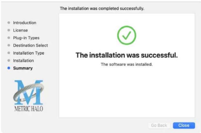
If you do not see the "Installation Successful" message, contact MH Support.
- The final step is to go to https://www.ilok.com/ and ensure you are up to date with the latest version of the iLok License Manager. Use the iLok License Manager to install the software license to your iLok key or directly to your computer.
That's it! Enjoy using Metric Halo plug-ins!
Windows
Please note – The following graphics show installation on an Windows 10 system; the process may be slightly different in other versions of the OS, but the basic concepts are the same. Small details such as file sizes shown may vary with subsequent releases.
- Double-click the "MHProductionBundleInstaller_v4.x.x.xxx" application

MH Production Bundle Installer
• The installer dialog will appear:

Welcome Dialog
Click "Next" to proceed.
- Read the Metric Halo License Agreement:

License Agreement
After you have read it, click next to "I accept the terms of the License Agreement" and click "Next".
- Custom Setup Options
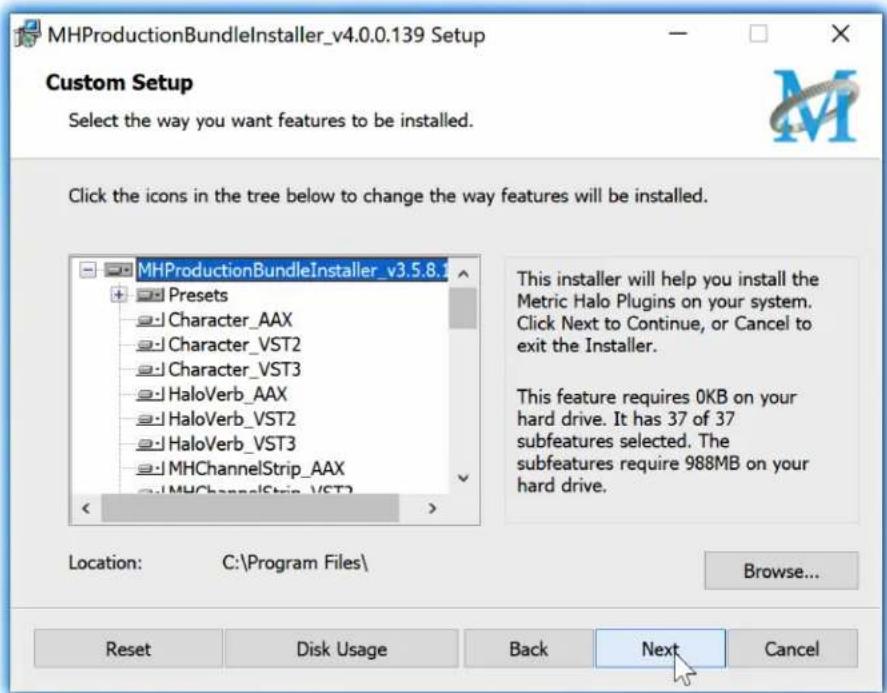
Custom Setup
The Windows installer Custom Setup page allows you to refine the features to be installed and their location.
By default, the full bundle with VST2, VST3 and AAX will be selected for installation to the C:\Program Files\ folder. Click Browse to change the installation target folder.
We recommend that you use the file path that will allow your host software to recognize the plugins. See your host software documentation.
When you have made your selections, click "Next" to continue.
- The next page is a confirmation to continue, offering a last chance to go back and review your selections from the previous window:

Ready to Install
Click "Back" to return to the Setup page, "Cancel" to cancel the installation, or click "Next" to continue.
- A final dialog before executing the installation process is a security confirmation, providing a verification of the location of the installer executable and information regarding the publisher of the installer package and its contents:

Final installer verification and permission to execute
Clicking "Show Details" and digging through the ensuing submenus will reveal signing credentials and other data for confirming the legitimacy of the installer executable.
Click "Yes" to proceed with the installation.
- The Setup Wizard will install and register the files:

Installation in Progress
- Once the installer has finished, you will see this dialog:
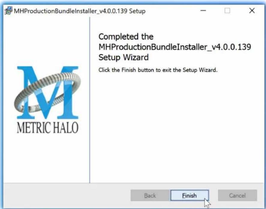
Installation Complete
If you do not see this installation "Completed" dialog, contact MH Support.
- The final step is to go to https://www.ilok.com/ and ensure you are up to date with the latest version of the iLok License Manager. Use the iLok License Manager to install the software license to your iLok key or directly to your computer.
That's it! Enjoy using the Metric Halo Production Bundle!
Update Notification (all platforms)
All Metric Halo Production Bundle plug-ins will automatically check for newer version availability (if your computer is connected to the internet).

Plug-in Update Alert
If a new version is found, the Metric Halo icon in the plug-in header bar will sport a lovely red dot. Click on the dotted icon and check the Update Notification tab for release notes and download instructions.
4. Plug-In Header Bars
All Metric Halo family plug-ins display the MH control bar directly above the processor control UI. This control bar is very helpful for organizing your MH presets, as it allows you to organize and access all your presets across all supported plug-in formats on Mac, Windows and our hardware DSP via MIOConsole3d.
It is especially useful in that, regardless of platform, it provides a straightforward, powerful and consistent processing workflow wherever you might be working.
With the constant evolution of computer capabilities opening the door to new production techniques and music delivery formats, the differences between DAW software workflows have become ever more diverse. Many of the major DAWs provide their own plug-in headers within every plug-in instance window, providing their own feature set catering specifically to their internal workflow.
Conversely, other equally popular DAWs provide no added feature support for plug-ins (such as plug-in parameter Undo/Redo), opting instead to insert plugs as a straight processing block.
The MH family plug-in header bar bridges that gap by offering the most asked for plug-in functions in a simple GUI, making all of our plug-ins functions and their presets available to every user on every platform.
The plug-in header bar has two rows of controls, with the Metric Halo logo icon at the top row left.
The top row handles plug-in operations, including update notification and download, access to MH online resources, GUI preferences, tooltip help, A/B parameter snapshots, snapshot Blend, plug-in Undo/Redo, Compare and soft Bypass.

MH Plug-in header (default setting: eq and dynamics graph display closed)
The lower row (with the 'hamburger' menu icon at the left) is all about preset management.
The menu includes organizational and preset import/export features for sharing saved preset files with the outside world, and restoring presets from early days MIO and MH plug-in versions.
Plug-In Header: Top Row

Metric Halo Header Icon
Clicking the MH icon expands the entire plug-in window to the right and opens a multi-function control sidebar with the Preferences tab in focus:

Preferences tab (example shown is SuperGate with sidechain filter graph closed)
This sidebar has context-sensitive tabs across the top for GUI Preferences (shown above), About, and Current Release Notes.

Plug-in control pane tabs
When updates are available for download from Metric Halo, the MH icon will sport a blatant red dot (shown in the header map at the top of this page) and an Update tab is added to the sidebar. These tabs are dynamic by design, and additional tabs may appear as new content becomes available.
To close the sidebar, click the MH icon again, or the "X" at the right edge of the tab bar.
Preferences tab
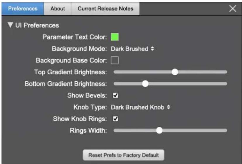
standard plug-in UI Preferences
The Preferences tab provides controls to modify the color scheme of text and graphical elements.
Initially added in response to requests from users with various visual impairments, in practice the ability to match the color of the plug-in to the mixer strip where it resides makes for a nice improvement in workflow.
Shown above are the basic parameter controls used by the majority of Production Bundle plug-ins.
More complex processors, such as ChannelStrip with multiband EQ and dynamics graph grids, will have additional preferences to further customize those UI elements. Processors with simpler graphics will have fewer UI preference controls.
UI parameter changes are live, so you can see changes to the plug-in graphics as you make them. This includes colors, gradients, graphic element show/hide, knob types and bevels.
Clicking color selection swatches opens the standard OS color pickers window with the eyedropper tool for sampling any color visible on your display.
UI Preferences functions are listed on the next page.
Note: The color scheme you set will be saved to the computer and automatically applied to the next instance of that plug-in type of whatever native format, even on another DAW.
You can always revert to the factory default settings by clicking the Reset Prefs to Factory Default button at the bottom of the Preferences pane.
Complete Plug-in Preferences List
The following is a list of all the preferences available across all of the plug-ins. They don't all apply to every plug-in, but you can refer here to find the documentation for the prefs that that are displayed in the actual plug-in.
- UI Preferences
- Parameter Text Color: sets the text color of all click-to-enter numeric readouts.
- Background Mode: selects the background type and texture.
Brushed background modes place an uncolored textured metal graphic behind the control elements. Color and Gradient controls will not affect the Light and Dark Brushed backgrounds.
- Light Brushed: a light brushed metallic facing with mild gradient lighting (the "vintage" Production Bundle faceplate).
- Dark Brushed: a dark neutral brushed metal facing with a stronger gradient and lighting effect
- Flat Color: select the background color with the Background Base Color picker.
- Gradient Color: select the background color with the Background Base Color picker and adjust Top Gradient Brightness and Bottom Gradient Brightness to taste
-
Grad w/Hits: same as Gradient Color with two mild rack light sources from above and one centered below
-
Background Base Color: when in color background modes, sets the background color
- Top Gradient Brightness: when in gradient background modes, sets the top gradient brightness
- Bottom Gradient Brightness: when in gradient background modes, sets the bottom gradient brightness
- Show Bevels: show/hide shaded edge and processor section separator bevels
- Knob Type: select from six "physical" knob types, or no knob at all
- Show Knob Rings: show/hide the colored rings surrounding parameter knobs
- Rings Width: widen/narrow the colored rings surrounding parameter knobs
- Show Band Swatches: show/hide the color swatches above each EQ band enable switch (used to set the color of each EQ band)
- Swatch Alpha: opacity control for the band color swatch buttons (does not affect Band Color selection)
- Show Graph Grids: show/hide the numeric grids in dynamics and EQ graph displays
- Graph Grid Color: set the color of the numeric grids in dynamics and EQ graph displays
- Graphs Background Color: set the background color of the dynamics and EQ graph displays
- Fill EQ Curves: shades the area of deviation of each eq band from 0dB reference (makes it easier to see the effect of each filter band amongst multiple active filters)
• EQ Colors
- Overall EQ Curve Color: sets the color of the aggregate EQ energy curve (the total sum effect of all active bands)
- Band 1 Color: sets the color of filter band 1 UI elements
- Band 2 Color: sets the color of filter band 2
- Band 3 Color: sets the color of filter band 3
- Band 4 Color: sets the color of filter band 4
- Band 5 Color: sets the color of filter band 5
- Band 6 Color: sets the color of filter band 6
- Sidechain EQ Colors
- Gate EQ Color: sets the color of Gate Sidechain filter band
- Comp EQ Color: sets the color of Comp Sidechain filter band
About tab
![Preferences About METRIC HALO ChannelStrip v.4.0.0.137 Metric Halo Website Metric Halo Tech Support Metric Halo FAQs ChannelStrip Product Page ChannelStrip Users Guide [PDF] Reveal Plug In File... Copyright © 2001-2024, Metric Halo. All rights reserved. Built: Feb 27 2024](/content/2026/05/940298/images/a5f77d80162c313765cebf5741fec8b74759cdf02f3bfa3d2b497d859497cca3.jpg)
About tab (ChannelStrip shown)
The About tab reveals the current plug-in version information and provides convenient web links to product info, support pages and the current manual on the Metric Halo main website.
Clicking the "...Users Guide [PDF]" link will open and display the plug-in manual version in your default web browser.
Reveal Plug-In File... will open the folder containing the current plug-in file, with the plug-in file itself selected. Very handy for troubleshooting on the fly.
Current Release Notes

Current Release Notes example
Current Release Notes lists a synopsis of major changes (a snippet of which is shown above), with feature and bugfix revisions for the most recent software releases listed below.
Please note that on Windows, the release notes will not be displayed in the pane, and a link to the release notes will be displayed instead. You can click the link to view the release notes using your current default web browser.
Update notification tab

Update tab with new version release notes header (text from update release notes omitted from above for brevity)
The Update tab will contain a link to download the new installer package in the header at the top of the pane.
Below the download link header, you will see new version information with a synopsis of the of major changes included in the update, and bugfix revisions for the most recent software releases listed further below. As with the Current Release Notes tab, Windows users will see a link to view the release notes using your current default web browser.
Click the Installer link to download, unzip and run the installer manually, preferably when your audio software is inactive so it can properly scan the new versions at launch.
Plug-in Snapshot Registers: A/B

Plug-in Header: Snapshot Registers: A/B
The A and B buttons control the A and B state registers. The A/B registers are used to store modified parameter snapshots in addition to the original saved preset called up by Compare.
The Blend function can be used to smoothly morph between the parameters set in the A and B registers, and Blend is a mappable parameter so it can be operated with external MIDI control. Details of the A/B Snapshot Blend feature follow on the next page.
For each of the A and B buttons the visual display tells you the state of the register:
• Light Grey means the register is empty
• Dark Grey means it has settings, but is unselected
- Blue means it has settings and is selected
You can perform the following actions:
- Clicking on an empty register takes a snapshot of the current settings and saves them to the register.
- Clicking on an unselected filled register copies the register parameters to the current active plugin settings.
- Clicking on a selected register toggles to the other register; this lets you toggle between the register settings without having to move the mouse
- Changing settings when a register is selected will update the settings in the register to reflect the change.
Snapshot Blend
The Blend button allows you to interpolate (or morph) between the parameter snapshots stored in the A and B registers. It becomes active when both A and B have a parameter set stored.
Blend is a MIDI-mappable parameter so it can be operated in realtime with external MIDI control and/or automated in the DAW. This allows you to automate a transition from the A → B register, the B → A register or any setting between the two.
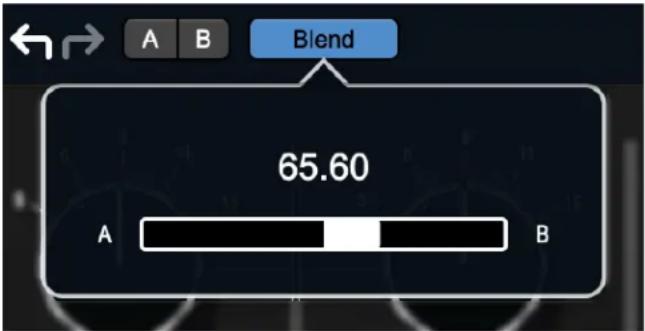
Plug-in Header: Snapshot Blend
The Blend button's visual display tells you the state of the register:
• Light Grey means it is empty
- Dark Grey means it has settings, but is unselected
- Blue means it has settings and is selected
Click on Blend to popup the blend control. Slide all the way to the left to apply the settings in the A register. Slide all the way to the right to apply the settings in the B register. Intermediate settings for blend will give you intermediate settings for any parameter that is different in register A and B. The blend control does not change the state of Bypass.
Note that the Blend is not a parallel processing mode where two instances of the processor are running the A and B settings and the output is a parallel blend of the two settings. Rather, Blend interpolates the parameter settings of the two registers to one instance of the processor. You can see the parameter controls move between A and B settings as you slide the Blend control.
The A/B and Blend settings are stored and recalled as part of the plug-in state, but are not saved as individual presets in the preset bar.
While you can use the blend with arbitrary A and B settings we find it works best when you craft the settings in the two registers in such a way as they are related to each other. Specifically, if an indexed (stepped) parameter is different between the two settings, the interpolated value will snap to one of the indexes between the two settings, which can be jarring.
It is best if the parameters that you blend are smooth parameters (e.g. gains, frequencies) and make sure the indexed parameters (enables, modes, band types) are set the same for both registers.
The easiest way to do this is to load the same setting into both registers and then tweak the settings of one of the registers.
This works especially well if you make one of the registers be the basic settings with all the gains or thresholds flattened out so that you can smoothly interpolate between a setting and effectively bypassed - we have found that this allows you to zero in a perfect configuration between too much and too little.
Plug-in Undo/Redo
All the plug-ins provide support for undo/redo from the plug-in header bar.

Plug-in Header: Undo/Redo
The left and right curved arrows represent Undo (Left) and Redo (Right). These arrows are grey when there is nothing to Undo or Redo.
The arrows are white when it is possible to Undo (Left) or Redo (Right). Clicking the left arrow when it is white will undo the last action you made in the plug-in. When you undo something that change is placed on the redo stack, and the Redo button will turn white.
Clicking the Redo button (when it is white) will restore the state that the last Undo changed.
If the Redo button is white and you make a change in the plug-in, the Redo button will go grey as the redo buffer will be cleared.
Help Button

Help Button
This button toggles the tooltip display. When enabled, tooltips will be shown when the mouse hovers over a control. When the tooltip display is disabled, you may still see tooltips by holding down the ? key and hovering over a control.
Graph Visible Selector

Graphs Closed

Graphs Open
This button toggles visibility of various response graphs. This button allows you to maximize screen real-estate while still providing details on the processing when they are needed. Not all MH family plug-ins will have this button, and on some plug-ins the button will have three panes. Clicking the button will step through the available views, with hidden panes shown darker in the button graphic.
UI Size Selector

UI Size Selector
This pull-down menu lets you set the plug-in UI size to taste.
The last selected setting for a plug-in processor will be applied to the next new instance you create of that same plug-in. For example, if you open an instance of ChannelStrip and set it to 80%, the next instance of ChannelStrip you create will also open at 80%.
Compare Button

Compare Button (inactive)

Compare Button (active)
To use the compare button, a preset must first be loaded. The compare button will be lit up when the current settings differ from the selected preset. If you click this button while it is lit, the preset settings will be restored, but you can still return to the changes you made by clicking on the button again. It is important to note that any changes you make to activate the compare light are always for comparison to the last loaded preset.
Soft Bypass

Soft Bypass Button (not bypassed - plug-in is processing)

Soft Bypass Button (bypassed - plug-in is not processing)
When glowing yellow, this button will maintain the time delay through the channel and will continue to show metering, but will cleanly disable the processing.
For MH 3d hardware users: A note regarding plug-in Sidechains
In host-based DAWs, the mechanism for routing signals to plug-in sidechain inputs is handled within the DAW itself in a separate routing UI from the plug-in.
In MIOConsole3d, plug-ins which support external sidechain inputs are assigned from within the plug-in UI (as shown below).

MIOConsole3d ChannelStrip header
In MIOConsole3d, sidechain inputs may be routed from any input or bus available in the system, except for the Main bus. These routes are naturally going to be different from what would be assigned in a DAW session.
For this reason, external sidechain assignments are the one parameter which can not translate between a host-based DAW preset and the same preset opened within MIOConsole3d.
Plug-In Header: Preset Row

"Hamburger" menu: Preset operations
Plug-in Hamburger menu
The preset and parameter functions within the hamburger menu break down as follows:

- Save Parameters saves the current plug-in parameters to the current preset.
- Save Parameters As... opens a dialog box where you can name and choose a category to save your current plug-in settings.
- Rename Current Preset... lets you rename the current preset.
- Delete Current Preset... deletes the current preset.
- Create New Category... lets you create a new preset category for the current plug-in type.
- Delete Current Category... deletes the current preset category.
- Copy Parameters copies the current parameter set so you can paste them to another instance of the same type plug-in.
- Paste Parameters pastes the copied parameters. Note that pasting a parameter set over an existing named preset will change the preset name field to: [No Preset].
- Factory Default loads the factory default settings for this plug-in.
- Reveal In Finder opens the folder in which the current preset is saved.
Preset Step-Through Buttons

Preset Step-Through Buttons
These buttons step through Factory and User Presets in succession, as they are listed in the Preset Selector window. The left arrow chooses the previous preset. The right arrow chooses the next preset.
Preset Name/selector menu:
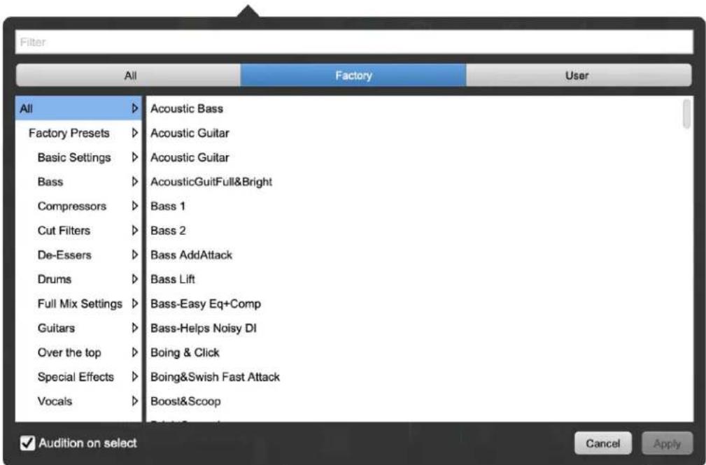
Plug-in Header: Preset selector menu (ChannelStrip shown)
The Preset selector will open to show all the available preset categories, and the presets within those categories.

Preset selector menu: Audition on select
With "Audition on select" enabled at the bottom of the window, selecting a preset will temporarily load those parameters so you can hear the effect on the audio you are playing, without actually committing to the preset.
Click Cancel to revert to your previous settings and close the selector window.
Hit Apply to commit the new preset parameters and close the preset selector window.
5. Operation
As with most channel strips, ChannelStrip provides many copies of controls that are all operated in a similar manner. The ChannelStrip user interface uses a few different control elements to control all of the processing. These elements are:
Control Knob
Control Knobs are used to control the value of various continuous parameters of a process. Examples of these types of parameters include: Attack time, Release Time, Threshold, etc. There are four styles of encoders:

Swept Knob
The rings around these encoders sweep from a minimum to maximum value, normally from left to right. One exception is the compressor threshold, which sweeps from right to left.
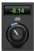
Plus/Minus Knob
The rings around these encoders start at 12 o'clock and sweep to either side. These knobs are used for gain control, where straight up is no gain change, turning to the left cuts the signal and turning to the right boosts it.

Spread Knob
The rings around these encoders start at 12 o'clock and spread to both sides equally as the control is increased. These knobs are used for bandwidth controls.

Limiter Knob
The ring around this encoder displays the amount of gain reduction from the limiter. The display sweeps around the encoder from right to left, with a fully left display indicating 12dB of gain reduction.
Control tips
You can change the value of each knob in a number of different ways.
- Click and drag the knob to change the value continuously.
- Dragging up or to the right will increase the value, while dragging down or to the left will decrease the value.
Hint: If you hold down the ⌘ (Command) key when you click, you will be able to adjust the value with finer precision.
- ∨ (Option)-click to reset any knob to its default value. You may also double-click a knob to reset it.
- Rapid parameter entry
- Double-click the numeric readout of the knob to type in a number directly. The text-entry field will remain active until you dismiss it by clicking somewhere else or hitting the return, enter, tab, or ⌘. (Command + .) keys.
- Hit return or enter to confirm the value and dismiss the pop-up.
- Hit the tab key to confirm the value and immediately activate the entry field for the next control. - -tab (Shift + tab) will display the entry field for the previous control.
- Hit ♜. (Command + .) or ESC (Escape) to dismiss the pop-up and cancel the change.
- When you enter a number into the pop-up entry, you can use a couple of abbreviations: "k" multiplies the number by 1000 and "m" divides the number by 1000. So if you want to enter 16,500 Hz you can just type 16.5k.
Toggle Button

Toggle Buttons
Toggle buttons are simple on/off switches. They light up when they are on and are dark when they are off. You toggle the state of the button by clicking on it. These buttons are used to enable processor sections, select keying sources and to switch the order of processing within ChannelStrip.
Fader
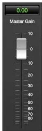
Master Fader
The fader is unique in that only one fader is used in the interface for ChannelStrip. It works in much the same fashion as the control knobs. Instead of dragging up/right or down/left to change the value, you
directly drag the fader knob. The other "tricks" described for the knobs also work with the fader. The fader is used to control the master output gain of the plug-in before the limiter stage.
Filter Type
Each filter band in the strip (6 EQ bands and 2 Side-chain bands) has a filter type control that allows you to choose the shape of the filter applied by that band. Each band provides 6 different types of filter shapes:
- Peaking/Parametric – a second order bell-shaped parametric boost/cut filter. The Gain control has a boost/cut range of ±24 dB. When the boost is greater than +15 dB the filter gains a resonant quality. The center frequency of the filter can be any frequency between 20 Hz and 20 kHz. The bandwidth of the filter is continuously variable between 0.1 octaves and 2.5 octaves.

Peaking/Parametric
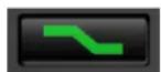
- Low Shelf – a shelving filter that applies boost/cut to low frequencies. Boost/cut has a range of ± 24 dB. The bandwidth controls the dip/peak that is added at the end of the transition band.
Low Shelf
- High Shelf – a shelving filter that applies boost/cut to high frequencies. Boost is limited to +12 dB (reflected in the EQ Transfer Function display) whereas cut goes to -24dB. The bandwidth controls the dip/peak that is added at the end of the transition band.

High Shelf
- High Cut – a 12 dB/octave high cut filter with a -3dB point that is continuously adjustable between 20 Hz and 20 kHz.

High Cut
- Low Cut – a 12 dB/octave low cut filter with a -3dB point that is continuously adjustable between 20 Hz and 20 kHz.

Low Cut
- Bandpass – a bandpass filter with 6dB per octave skirt on the high and low ends of the pass band. The width of the pass band can be adjusted between 0.1 octaves and 2.5 octaves and the center of the pass band is continuously adjustable between 20 Hz and 20 kHz.

Bandpass
You can select from these types via three different methods. Each time you click on the Filter Type control, the band will switch to the next type in the list (and wrap to the beginning when you hit the end of the list). If you click and hold the mouse button, a pop-up menu listing all of the types will appear after about
1/4 of a second. You can select the type directly from this pop-up menu. If you want to access the menu without having to wait, hold down the Mac ^ (Control) key when you click or right-click (Mac/Win).
Sidechain Routing Switch

Sidechain Routing Switch
Each sidechain routing switch allows you to control the signal sent to the sidechain input of its associated gate or compressor. By default, the level detectors in the dynamics processors key off of the signal that they are processing. Under some circumstances, you may want to use a different signal to open the gate or compress the signal. Most DAWs allow you to specify an input or bus as the source for ChannelStrip's sidechain input. The Sidechain routing switches allow you to choose the input to the level detector from the sidechain (key) input or the signal being processed. To toggle the state, click the Sidechain routing switch.
Sidechain Listen Button

Sidechain Listen (Disabled)

Sidechain Listen
(Enabled)
The sidechain listen button allows you to listen to the signal being sent to the gate or compressor sidechain input. This allows you to monitor the audio being routed from the key input, and hear the effect of sidechain filtering.
Compressor Character
Compressor Character Switch
The compressor character controls the time constants of the compressor section. It functions identically to the Filter Type control, except there are only four choices: Smooth, Warm, Fast and MIO. See the section on the compressor for more information.
ChannelStrip also uses a number of standard visual representations to give you feedback about what is happening within the processor. These elements are:
Input Meters

Gate/Expander Peak Meter
Compressor Peak Meter
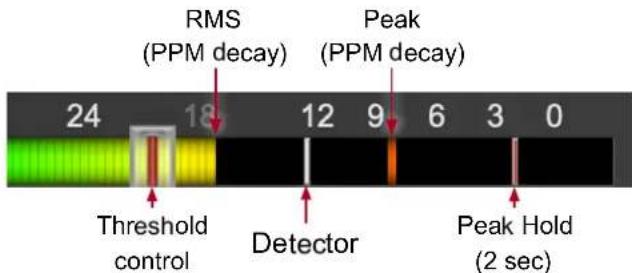
SpectraFoo™ multi-function metering is provided at the input stage of ChannelStrip's Gate/Expander and Compressor processing blocks.
- RMS level is indicated by the colored solid bar, which transitions from green at "safe" high-headroom levels to yellow at -18dBFS, then to orange and finally red approaching -6dBFS. The RMS meter uses the fast PPM standard for decay time (0.9 seconds per 20 dB) and the digital PPM standard legend for calibration.
- Instantaneous Peak is displayed by the floating colored pip which follows the RMS level bar color and decay standard as above.
- Temporary Peak Hold is show as a floating red pip with a hold time of 2 seconds.
-
On the dynamics sections (gate and compressor), the white floating pip indicates the current detector level. Detector display is after the Sidechain filter in the signal path, and the detector behavior itself varies depending on the mode of the dynamics processor:
-
The Gate/Expander uses a fast peak detector, with Attack and Release applied at the gain reduction stage.
- With the Compressor in MIO mode, the attack and release are applied to the envelope detector, and the gain reduction is driven directly from the detector. This is why, in MIO mode, the detector pip response visually slows down following the Attack and Release controls.
- The Smooth, Warm and Fast compressor modes employ the fast peak detector, with gain reduction controlled by Attack and Release as applied by each individual compression mode characteristic.
- For the dynamics sections the processor threshold is indicated by the red slider over the input peak meter. This slider can be manipulated directly with the mouse and tracks along with changes made by the Threshold knob.
- The top segment of the meter (above 0dB) is used as a clip indicator and is illuminated red if the input section of the processor detects an over. The clip light remains illuminated until you click on the meter. Option/Alt-click any meter to reset the clip lights on all of the meters in ChannelStrip.
When ChannelStrip is running in stereo mode, both the Gate/Expander and Compressor input meters show the higher of the two input levels and will detect digital clipping on either input channel.
Gain Reduction Meter

Gain Reduction Meter
The gain reduction meter, which has an orange bar and grows down from 0 dB, shows the amount of attenuation being applied by its associated dynamics processor. If you right-click on the meter, you may set the scale of the gain reduction meter to any of the following values:
54 dB, 24 db, 12 db, 6 db, 3 db
Peak, RMS, VU Output Meter with Peak Hold
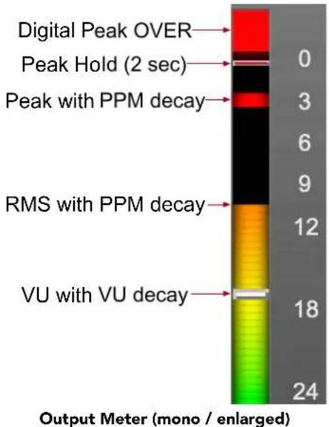
For the main output stage of ChannelStrip we have provided meters driven with SpectraFoo™ metering technology. These meters show digital Peak, Peak Hold, RMS level and VU level.
Both the Peak and RMS level are represented with fast PPM ballistics.
The instantaneous Peak level is represented by the floating colored pip. Peak Hold is 2 seconds, indicated as a red floating marker pip.
The RMS level is the solid colored bar which transitions from green at "safe" high-headroom levels to yellow at -18dBFS, then to orange and finally red approaching -6dBFS.
The VU meter is the white floating marker pip showing IEEE standard 300 ms RMS average level.
When ChannelStrip is on a mono insert there will be a single meter.
The output section clip lights activate if there is an over in the output stage or in any of the processing section input stages. It is reset by clicking on the meter; Option/Alt-click any meter to reset the clip lights on all of the meters.
A Note About Clipping Indicators:
The clip lights do not mean that the plug-in is clipping; it means that the audio level in the DSP is currently over 0 dBFS. If you do not lower the signal level you run the risk of actually clipping the input of another processor or D/A convertor.
EQ Transfer Function
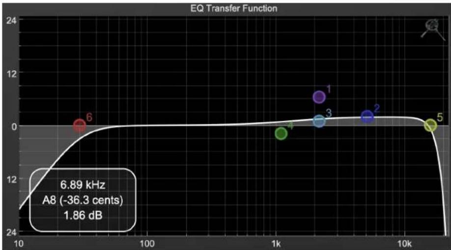
EQ Transfer Function
The following information on the EQ Transfer Function and Spectragraph Analyzer apply to the EQ processing block as well as the sidechain filter displays of the gate and compressor.
The horizontal axis provides frequency calibration in Hertz (Hz). The vertical axis provides level calibration in decibels (dBr). The heavy line (white by default) indicates the relative change in level at each frequency that is created by the combined effects of all of the active filter bands in the equalizer.
Each EQ band is represented by a colored dot in the transfer function. The color of the dot matches the color of the knob rings for the corresponding EQ band.
The dot represents the center frequency or knee of the filter band, and acts as a control handle for the band within the transfer function field.
The band that is currently being edited will be highlighted and displayed along with the overall response curve. If the associated band is a symmetrical filter (parametric) there will also be two smaller colored dots that can be used to control the Q of the filter.
Clicking on a band handle dot and dragging will allow you to adjust the frequency and gain of the associated band.
- Ⓧ (Command)—click or double-click the dot to toggle the band enable (single-click to disable a band when Auto Enable Bands is turned on).
- Click and drag the smaller dots associated with a larger dot to adjust the filter Q. You can also (Option)-click the dot to adjust the Q (dragging left increases the Q, right decreases the Q).
- ⌘ (Command + Option)-click the dot to switch the band filter type.
In the transfer function field, multiple filter bands may be temporarily grouped by shift-click or click-drag selection of the filter control handles.
To dismiss the filter curve, click anywhere in the black area of the transfer function. This will deselect the filter, and the only trace displayed will be the master eq curve.
Transfer Function options
Right-clicking the EQ transfer function background brings up an EQ functions control menu.
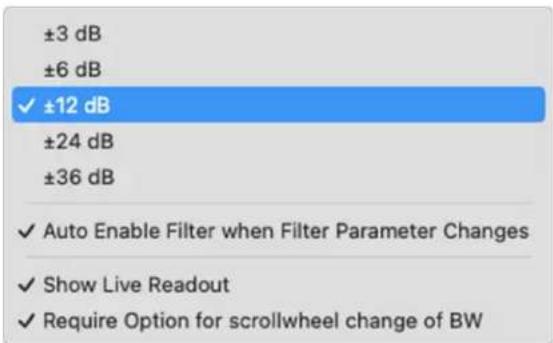
- EQ display scale: Sets the EQ curve dB scale from ± 3 to ± 36 dB.
- Auto Enable Bands when band parameter changes: Automatically enables a filter band when one of its parameters is adjusted within the EQ Transfer Function. This preference will apply to all instances of Sonic EQ.
Note that the Auto-Enable applies only to the filter band enables, and does not affect the master plug-in Bypass state. Auto Enable does not apply to the 6-Band EQ control knobs or the Special filters.
- Show Live Readout (shown on the previous page): Enables an overlay in the lower left corner of the transfer function which displays the relative amplitude of the master EQ curve at the frequency indicated by your mouse cursor. Moving the cursor off the EQ display hides the readout. Live Readout control is enabled per instance.
- Require Option for scrollwheel change of BW: Enabled by default, this control requires the Option modifier key to change the Q parameter using a mouse scrollwheel. Scrollwheel filter width control works for filter band knobs (one at a time) and selected filters in the transfer function display (multiple selections supported).
Spectragraph Analyzer
Clicking the SpectraFoo™ logo in the upper right hand corner of the transfer function will activate the spectragraph, showing the realtime frequency analysis of your signal overlaid on the Transfer Function EQ curve:

The traces are:
- White: Left channel instantaneous display
• Red: Right channel instantaneous display
• Yellow: Left channel average display
• Blue: Right channel average display
The instantaneous trace updates in real-time, allowing you to see the immediate peak level of your audio. The average trace displays the level as averaged over a short period, giving you a more general view.
The spectragraph analyses the signal post-filter, allowing you to see the effect of your EQ filters.
To disable the spectragraph entirely, click the active Spectrafoo icon.
If you right-click or ^ (Control) click on the Spectrafoo icon, you will see a menu to set options for the spectragraph:

• Show Instantaneous Trace: Toggles the instant response traces for both channels.
• Show Average Trace: Toggles the averaged response traces for both channels.
• Show Left Channel: Toggles the left channel spectragraph display.
• Show Right Channel: Toggles the right channel spectragraph display.
These settings are stored independently for each instance of ChannelStrip.
Note that just the Left channel display is shown by default.
Controls for Left and Right channel will only be available in stereo instances of ChannelStrip.
Dynamics Knee
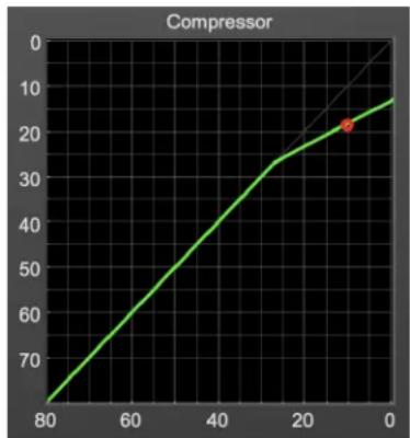
Dynamics Knee
ChannelStrip contains a Dynamics Knee diagram for the gate and compressor processing sections. The diagram provides feedback on the response of the associated dynamics processor. Both the horizontal and vertical axes are calibrated in dBFS. The horizontal axis corresponds to the input level and the vertical axis represents the output level. The heavy line shows the dynamic of the associated processing block. This means that if you sent in a sine wave at a given input level, the output level would be equal to the level shown on the graph. When the processor is working with real dynamic signals, the graph is a good approximation of the response when the attack is fast and the release is slow.
In most cases, however, the dynamic response of the processor will not match its static response. In order to represent this, we have included a "bouncing ball" meter for both the gate and the compressor. This metering is shown as a red circle that is overlaid on the knee diagram. The red circle is placed so its horizontal position is equal to the instantaneous input level and its vertical level is equal to the instantaneous output level. Examining this meter while you are adjusting the dynamics controls will provide you with a great deal of information about how the processor is operating and how the controls interact.
6. Processing
A Detailed Description
In this chapter we'll discuss what each processing block does and how the controls work.
![graph TD A["Input"] --> B["Phase Invert"] B --> C["Input Gain"] C --> D["Delay"] D --> E["Gate"] E --> F["Comp"] F --> G["EQ"] G --> H["Gain"] H --> I["Limiter"] subgraph Inputs J["Key Input"] K["Sidechain Select "SC""] L["Gate SC EQ"] M["SpectraFoo"] N["Output"] end subgraph Gates O["Comp…](/content/2026/05/940298/images/157de1645ff0049a95465e919f2aeec4814864c274d04625274e34007f0c0bec.jpg)
Signal Flow: Compressor is Pre-EQ
![graph TD A["Input"] --> B["Phase Invert"] B --> C["Input Gain"] C --> D["Delay"] D --> E["Gate"] E --> F["EQ"] F --> G["Comp"] G --> H["Gain"] H --> I["Limiter"] subgraph Sidechain Select J["C"] --> K["Gate SC EQ"] end subgraph Spectragraph Toggle L["SpectraFoo"] --> M["Output"] end N["Key Input"] -…](/content/2026/05/940298/images/505da7176918eab4d09b6f0391463f73bd3a3ab75087dac712a1c7c65c6601af.jpg)
Signal Flow: Compressor is Post-EQ
The block diagrams above illustrate the overall structure of the processing system provided by ChannelStrip. The diagrams do not indicate the various metering blocks. The configuration is controlled by the "Post EQ" button in the compressor and it changes the path of the signal through the processor. The internal signal switching provided by ChannelStrip allows you to explore the various effects of re-ordering processing blocks without having to waste time stopping the transport, removing and reinserting plug-ins and then finally restarting the transport.
Now lets examine the various processing blocks indicated in the diagram.
Input Conditioning
After the signal is routed to ChannelStrip it runs through the phase invert block. This block is controlled by the "ø Inv" switch. When the phase invert is enabled the polarity of the signal will be flipped. The signal is cross-faded between the uninverted and inverted states so the signal level will drop briefly when you flip the state of the phase invert switch, but it will not introduce a glitch or click into your audio.
After the phase invert block the audio is routed through an input gain block that provides input gain of up to +24 dB. You can use this gain to condition signals that are low in level.
This input gain may also be used to pad out signals by up to -24 dB. While you may find this attenuation useful to just bring down the level through the strip simply and quickly, you must realize that this gain is applied after the signal reaches ChannelStrip and will not pad out any clipping that occurs in the A/D converters or in a plug-in that is inserted before ChannelStrip.
The input gain is controlled by the "In Gain" knob.
Gate/Expander
The next processing block is the Gate. The gate is used to adjust the low level dynamics of the signal being processed. Through the use of the external side-chain the gate can be used to do acoustic triggers. In addition, the side chain filter may be used to make the control of the dynamics frequency sensitive. This can be useful when you are trying to gate out a noisy signal that has a specific, very strong signal in a limited frequency range when you want the gate to open.

Gate/Expander
Theory Of Operation
Based upon your setting for the sidechain routing switch, either the Pro Tools sidechain input signal or the channel signal is fed to the sidechain filter. The sidechain filter provides one band of equalization that may be used to accentuate or cut certain frequencies (parametric or shelf filters) or limit the key to a certain range of frequencies (cut or bandpass filters). You control the filter type and the filter parameters with the filter type button and the "dB", "Hz" and "BW" knobs.
You can enable the side chain filter with the green "SC Ena" button.
After the sidechain signal has been processed by the sidechain filter it is measured by a level detector that determines the instantaneous level of the signal (in the case that ChannelStrip is running in stereo mode the detector is linked with the other channel in the stereo pair and the higher level of the two channels is used).
When the gate is enabled the signal will be attenuated based on how much the detected level is below the threshold you set with the "Thresh" knob.
The dynamic behavior of the opening and closing of the gate is controlled with the "Attack" and "Release" knobs.
Gate Enable
This button is in the Master Enables section. When this button is off, the gate will not change the signal.
Threshold Control
The "Thresh" knob controls the level at which the gate opens and closes. When the detector level is above the threshold level the gain through the gate is 0 dB. When the detector level is below the threshold level, the gain is reduced at a ratio of 1:2. This means that if the detector is 3dB below the threshold the signal output will be 6dB below the threshold or 3dB below the input level.
The gate threshold level is also indicated by the red bar above the gate input meter. You can adjust the threshold level using this indicator as well as by using the "Thresh" knob.
Attack Control
The "Attack" knob allows you to adjust how quickly the gain reduction is decreased to 0 dB when the detector level goes above the threshold level. When this control is set to Auto, the attack rate is controlled by how much the detector level is above the threshold. When you set the attack to another value other than "Auto" that value, measured in milliseconds, will control how quickly the gate opens. The maximum value is 100 milliseconds. Attack times other than auto are especially useful when using the gate as a trigger. If the key signal is a little early you can use the attack to delay the trigger slightly. It is also useful to remove the initial transients of impulsive sounds.
Release Control
The "Release" knob controls the release time of the gate. This parameter is measured in milliseconds and can range from 5 ms to 5 sec. The release time controls how quickly the gate closes after the detector drops below the threshold value. For settings below 90 ms or so the gate closes pretty abruptly and may introduce unwanted artifacts into your audio, depending on the signal.
Using The Sidechain Key Input w/Selectable Filter
The gate provides a sidechain that processes audio before the detector determines the current level. The sidechain can process either the channel signal or some external side chain input signal.
Sidechain Listen Button
This button (the speaker icon next to the Sidechain Enable) allows you to monitor the audio being sent to the gate's detector. This will allow you to listen to external audio that is being routed to the sidechain, and also hear the effect of the sidechain filter. When you are done listening to the sidechain, click this button again to hear ChannelStrip's normal output.
Sidechain Routing Button
This button (labeled "C" in the illustration) is used to control the routing of the input signal to the gate sidechain. When the button is in the "C" state, the signal used by the sidechain is the signal being processed by ChannelStrip. When the button is in the "SC" state, the signal used by the sidechain is the input or bus selected in the "side chain input" pop-up in your DAW's plug-in window header. If nothing is selected in that pop-up, the input to the sidechain will be silence and the gate will never open.
Sidechain Filter Enable
This button (labeled "SC Ena") allows you to toggle the sidechain filter in and out of the audio path to the detector.
Filter Type Button
This button (indicating a peaking/parametric filter in the illustration) is used to select the filter type of the single band of side chain EQ. You may choose from the 6 different types of filters detailed in the filter type section in "Operating the Strip".
Filter Band Boost/Cut Control
Use this knob (labeled "dB" in the illustration) to adjust the gain of the filter band for the peaking, high and low shelf filter types. This parameter is ignored for the other filter types. In the shelving filters the maximum boost is +12 dB and the maximum cut is -24 dB. In the peaking filters the maximum boost/cut is ± 24 dB. When you increase the boost for a filter band above 15 dB, the filter gets nicely aggressive and resonant.
Filter Band Frequency
Use this knob (labeled "Hz" in the illustration) to adjust the characteristic frequency of the filter. For the peaking and bandpass filter types this controls the center frequency of the filter. For the high and low cut filter types this control adjusts the 3 dB point of the filter. For the shelving filters this control adjusts the shelf transition point.
Filter Bandwidth
Use this knob (labeled "BW" in the illustration) to adjust the characteristic width of the filter. This control only has effect for peaking, shelving and bandpass filter types. Please note that this parameter controls the bandwidth (measured in octaves), not the quality factor (or "Q"). If you have been using Q controls, the numbers will be backwards from what you are used to. Small numbers mean narrow filters and large numbers mean wide filters. For peaking and bandpass filter types, this parameter controls the bandwidth of the filter in octaves. For the high and low shelving filter types this parameter adjusts the amount of dip/peak and the slope of the shelf. When this parameter is set to 0.1 you will get the largest dip/slope available and when the parameter is 2.5, you will get a classic first order shelf (which has a transition band that is about 1 decade wide; e.g. if it is a high shelf with a frequency of 10 kHz and a gain of 10 dB, the gain will be at 0 dB near 1 kHz).
Compressor
Depending on the state of the "Post EQ" button (the default state is for the compressor to come first in the signal chain), the next block in the signal processing chain is the compressor. The compressor is used to adjust the high-level dynamics of a signal. As with the gate, the sidechain can be used to make the compressor frequency sensitive (so it can be used like a de-esser) or to reduce the gain of the signal in response to some external event (this allows the compressor to be used like a ducker or for other creative effects).

Compressor
Often, you will want to compress the signal before you equalize it. Sometimes you will need to equalize the signal before you compress it. ChannelStrip provides that flexibility with the "Post EQ" button. This is a very important part of ChannelStrip because it allows you to test different processing scenarios quickly and easily. It also allows you to compare the two different approaches without having to stop the transport so you can get a much more visceral comparison.
Theory Of Operation
The operation of the compressor is very similar to the gate. Based upon your setting for the sidechain routing switch, either the sidechain input signal or the channel signal is fed to the sidechain filter. The sidechain filter provides one band of equalization that may be used to accentuate or cut certain frequencies (parametric or shelf filters) or limit the key to a certain range of frequencies (cut or bandpass filters). You control the filter type and the filter parameters with the filter type button and the "dB", "Hz" and "BW" knobs.
You can enable the sidechain filter with the enable button. After the sidechain signal has been processed by the sidechain filter it is measured by a level detector that determines the instantaneous level of the signal (in the case that ChannelStrip is running in stereo mode the detector is linked with the other channel in the stereo pair and the higher level of the two channels is used).
When the compressor is enabled the signal will be attenuated based on how much the detected level is above the threshold you set with the "Thresh" knob and what compression ratio is set with the "Ratio" knob.
The dynamic behavior of the opening and closing of the gate is controlled with the "Attack" and "Release" knobs and the compressor character switch.
Audio Dynamics
Compressors are important in controlling the dynamic range of the source material you are working with. While the instruments, your ears, the microphones and your digital audio workstation all have dynamic ranges that are greater than 100 dB, most reproduction and delivery media have significantly reduced dynamic ranges. Compression is used, in its simplest form, to help reduce the dynamic range of your project or elements of the project to a range that is reproducible. It does this by making the soft material louder and the loud material softer. This type of processing can also be used to change the character of the sound instead of just adjusting the dynamic range. The compressor in ChannelStrip excels at both types of processing.
Compressor Enable
This button is in the Master Enables section. When this button is off, the compressor section will not change the signal. The order of this button will change depending on whether the compressor is set to "Post EQ".
Post EQ
The "Post EQ" button places the compressor section after the equalizer in the signal chain. By providing the capability to switch the routing on the fly, ChannelStrip allows you to determine the most effective routing for your particular signal quickly and easily.
Auto Gain
When the "Auto Gain" button is enabled the compressor automatically adjusts the makeup gain in the compressor output stage so that if the manual "O Gain" knob is set to 0 dB the static gain reduction for a 0 dB input level will be about 7 dB. This number was chosen because it works well with the default settings of the "Attack" and "Release" knobs to provide enough pad to not clip fast transients. The "O Gain" knob will apply additional trim to the internal automatic gain. If the threshold is set very low (e.g. -60 dB) and auto gain is enabled, you will not be able to add very much manual gain (only about 1 – 2 dB) even though the readout on the knob will go up to +30 dB. This is an internal limitation of the compressor.
Compressor Knee Control
The "Knee" knob allows you to adjust shape of the compressor transfer function when the Compressor Character is set to MIO (the Knee control has no effect for the other compressor character algorithms and will not be visible in those modes).
When the Knee control is set to 0, the transfer function of the compressor is a classic "hard-knee" in which the compressor applies no gain reduction when the detector is below the threshold, and the gain is reduced by the ratio when the detector level is above the threshold.

Knee Control at 0
When you increase the Knee parameter from 0 to 1 the knee of the transfer function gradually softens until the compressor functions as a soft-knee compressor when the Knee parameter is 1.

Knee Control at 1
You can also adjust the Knee parameter to negative values, which has the effect introducing a "kink" in the compressor transfer function at the threshold. This can yield useful results on percussive material.

Knee Control at -0.5
Manual Make-Up Gain
The "O Gain" knob allows you to manually adjust the makeup gain applied to the signal after the gain reduction applied by the compressor. If the Auto Gain switch is off, this is the amount of makeup gain applied. If the Auto Gain switch is on, then this parameter is a trim added to the internally computed makeup gain. The makeup gain is enabled and disabled along with the rest of the compressor.
Compressor Character
Use the compressor character button to determine the overall dynamic characteristics of the compressor. There are three "classic" ChannelStrip settings to choose from:
- Smooth – appropriate for full mixes or single instruments that do not have big transients. Provides very smooth compression with few artifacts, no distortion and limited transient control.
- Warm – the most versatile setting for the compressor. Balances transient control with audibility of the compression. Appropriate for a wide range of signals including harmonic instruments with large transients (e.g. Plucked bass).
- Fast – provides significant transient control at the expense of transparency and added distortion. Appropriate for impulsive signals with significant transients. Supports very fast (e.g. 1 sample) gain reduction attacks.
- MIO – provides the compressor characteristics from the MIOStrip compressor that runs on our interfaces. This compressor algorithm is very different from the other three.
The MIO compressor generates its gain reduction directly from the detector level. The Attack and Release parameters directly control the measurement of the detector level. This allows the MIO compressor to function as a limiter as well as a compressor and a leveling amplifier.
The MIO compressor algorithm also supports an adjustable Knee. In general, the MIO algorithm is more flexible and controllable than the other algorithms, and as a result, we have made it the factory default for ChannelStrip.
Threshold Control
The "Thresh" knob controls the level at which the compressor begins to reduce the gain applied to the signal. When the detector level is below the threshold level, no gain reduction is applied. As the detector level increases above the threshold level, the gain is reduced as indicated by the knee diagram associated with the compressor. The compressor knee is soft. The ratio increases as the difference between the detector level and the threshold increases.
The compressor threshold level is also indicated by the red bar above the gate input meter. You can adjust the threshold level using this indicator as well as by using the "Thresh" knob.
Ratio Control
The "Ratio" knob controls the 'terminal' ratio used to compute the gain reduction of the compressor. When the ratio associated with the soft knee hits the ratio specified by the ratio knob, the knee 'hardens' and remains at the same constant ratio. If you set the ratio to 1000:1 the compressor will have a soft knee for all input levels and thresholds. This makes the compressor work like a classic all tube limiter/compressor.
Attack Control
The "Attack" knob allows you to adjust how quickly the gain reduction is increases when the detector level goes above the threshold level. This control is calibrated in milliseconds and values range from 0 to 500 ms. The compressor has an 8 sample look-ahead buffer that allows it to have an "instant attack" when you set the attack time to 0. Fast attack times will control the transients of impulsive sounds. Use longer attack times to let the transients through but control the sustains.
Release Control
The “Release” knob controls the release time of the compressor. This knob is calibrated in milliseconds and can range from 5 ms to 5 sec. The release time controls how quickly the gain reduction returns to zero after the detector drops below the threshold value. For settings below 40 ms or so the compressor releases pretty abruptly and may introduce unwanted artifacts into your audio, depending on the signal. In addition, be careful making the release time faster than the attack time.
Using The Sidechain Key Input w/Selectable Filter
The compressor provides a sidechain that processes audio before the detector determines the current level. The sidechain can process either the channel signal or some external side chain input signal.
Sidechain Listen Button
This button (the speaker icon next to the Sidechain Enable) allows you to monitor the audio being sent to the compressor's detector. This will allow you to listen to external audio that is being routed to the sidechain, and also hear the effect of the sidechain filter. When you are done listening to the sidechain, click this button again to hear ChannelStrip's normal output.
Sidechain Routing Button
This button (labeled "C" in the illustration) is used to control the routing of the input signal to the compressor sidechain. When the button is in the "C" state, the signal used by the sidechain is the signal being processed by ChannelStrip. When the compressor is in the "SC" state, the signal used by the sidechain is the input or bus selected in the "side chain input" pop-up in your DAW's plug-in window header. If nothing is selected in that pop-up, the input to the sidechain will be silence and the compressor will never compress.
You can use the filter to achieve a de-essing effect by using the bandpass filter to only compress when the "ess" is present. You can also achieve a combined compression/de-essing effect by using a peaking filter to accentuate the "ess" frequencies and adjusting the threshold and ratio to perform compression when the "ess" is not present and limiting when the "ess" is present. Take a look a the presets for examples.
Sidechain Filter Enable
This button (labeled "SC Ena") allows you to toggle the sidechain filter in and out of the audio path to the detector.
Filter Type Button
This button (indicating a peaking/parametric filter in the illustration) is used to select the filter type of the single band of side chain EQ. You may choose from 6 different types of filters detailed in the filter type section in "Operating the Strip".
Filter Band Boost/Cut Control
Use this knob (labeled "dB" in the illustration) to adjust the gain of the filter band for the peaking, high and low shelf filter types. This parameter is ignored for the other filter types. In the shelving filters the maximum boost is +12 dB and the maximum cut is -24 dB. In the peaking filters the maximum boost/cut is ± 24 dB. When you increase the boost for a filter band above 15 dB, the filter gets very aggressive and resonant.
Filter Band Frequency
Use this knob (labeled "Hz" in the illustration) to adjust the characteristic frequency of the filter. For the peaking and bandpass filter types this controls the center frequency of the filter. For the high and low cut filter types this control adjusts the 3 dB point of the filter. For the shelving filters this control adjusts the shelf transition point.
Filter Bandwidth
Use this knob (labeled "BW" in the illustration) to adjust the characteristic width of the filter. This control only has effect for peaking, shelving and bandpass filter types. Please note that this parameter controls the bandwidth (measured in octaves), not the quality factor (or "Q"). If you have been using Q controls, the numbers will be backwards from what you are used to. Small numbers mean narrow filters and large numbers mean wide filters. For peaking and bandpass filter types, this parameter controls the bandwidth of the filter in octaves. For the high and low shelving filter types this parameter adjusts the amount of dip/peak and the slope of the shelf. When this parameter is set to 0.1 you will get the largest dip/slope available and when the parameter is 2.5, you will get a classic first order shelf (which has a transition band that is about 1 decade wide; e.g. if it is a high shelf with a frequency of 10 kHz and a gain of 10 dB, the gain will be at 0 dB near 1kHz).
Equalizer
The next processing section is the Equalizer. The equalizer may appear in the signal chain before the compressor section depending on the state of the "Post EQ" button in the compressor. The equalizer in ChannelStrip is a very flexible, fully parametric 6 band equalizer. Each band in the equalizer can be configured as any of the six available filter types. Each parameter in the equalizer is continuously adjustable throughout its entire range, so you can set the exact EQ that you need.

EQ Section
Theory Of Operation
The equalizer in ChannelStrip work just like every other EQ under the sun with the exceptions that it is more flexible, more efficient and sounds better. By adjusting the various parameters associated with each band in the EQ you can control the tonal and timbral balance of the signal. The resonance effect of the peaking filters provides a facility to recreate acoustic resonances that are lacking in the source material with which you are working. One of the nicest aspects of the filters in ChannelStrip is their time domain performance. These filters ring significantly less than comparable filters in other signal processors. This allows you equalize signals without the normal time smearing that you encounter with other equalizers.
Master Enable Button
This button is in the Master Enables section. When this button is off, the EQ section will not change the signal. The order of this button will change depending on whether the compressor is set to "Post EQ".
Filter Type Button
This button (indicating a peaking/parametric filter in the illustration) is used to select the filter type of the single band of side chain EQ. You may choose from 6 different types of filters:
- Peaking/Parametric – a second order bell-shaped parametric boost/cut filter. The Gain control has a boost/cut range of ±24 dB. When the boost is greater than +15 dB the filter gains a resonant quality. The center frequency of the filter can be any frequency between 20 Hz and 20 kHz. The bandwidth of the filter is continuously variable between 0.1 octaves and 2.5 octaves.

Peaking/Parametric
- Low Shelf – a shelving filter that applies boost/cut to low frequencies. Boost/cut has a range of ± 24 dB. The bandwidth controls the dip/peak that is added at the end of the transition band.

Low Shelf
- High Shelf – a shelving filter that applies boost/cut to high frequencies. Boost is limited to +12 dB (reflected in the EQ Transfer Function display) whereas cut goes to -24dB. The bandwidth controls the dip/peak that is added at the end of the transition band.

High Shelf
- High Cut – a 12 dB/octave high cut filter with a -3dB point that is continuously adjustable between 20 Hz and 20 kHz.
High Cut
- Low Cut – a 12 dB/octave low cut filter with a -3dB point that is continuously adjustable between 20 Hz and 20 kHz.
Low Cut
- Bandpass – a bandpass filter with 6dB per octave skirt on the high and low ends of the pass band. The width of the pass band can be adjusted between 0.1 octaves and 2.5 octaves and the center of the pass band is continuously adjustable between 20 Hz and 20 kHz.

Bandpass
Filter Band Color Swatch
Clicking the color swatch below the Filter Type button will open the OS color picker where you can change the color elements of that band. The swatch duplicates the EQ Colors controls found in the Plug-in Preferences pane.
De-selecting "Show Band Swatches" in the Plug-in Preferences will hide them from the EQ UI.
Filter Enable Button
Use this toggle button to enable each filter band. When the filter band is turned off the signal will pass through the filter unchanged.
Filter Band Boost/Cut Control
Use this knob (labeled "dB" in the illustration) to adjust the gain of the filter band for the peaking, high and low shelf filter types. This parameter is ignored for the other filter types. In the shelving filters the maximum boost is +12 dB and the maximum cut is -24 dB. In the peaking filters the maximum boost/cut is ± 24 dB. When you increase the boost for a filter band above 15 dB, the filter gets very aggressive and resonant. You can use this feature to good effect when you need to reconstruct a resonance for a recorded instrument that lacks one. For example, you could place a narrow +24 dB peaking filter between 60 and 80 Hz on a kick drum track that lacked a "belly" for the drum.
Filter Band Frequency
Use this knob (labeled "Hz" in the illustration) to adjust the characteristic frequency of the filter. For the peaking and bandpass filter types this controls the center frequency of the filter. For the high and low cut filter types this control adjusts the 3 dB point of the filter. For the shelving filters this control adjusts the shelf transition point.
Filter Bandwidth
Use this knob (labeled "BW" in the illustration) to adjust the characteristic width of the filter. This control only has effect for peaking, shelving and bandpass filter types. Please note that this parameter controls the bandwidth (measured in octaves), not the quality factor (or "Q"). If you have been using Q controls, the numbers will be backwards from what you are used to. Small numbers mean narrow filters and large numbers mean wide filters. For peaking and bandpass filter types, this parameter controls the bandwidth of the filter in octaves. For the high and low shelving filter types this parameter adjusts the amount of dip/peak and the slope of the shelf. When this parameter is set to 0.1 you will get the largest dip/slope available and when the parameter is 2.5, you will get a classic first order shelf (which has a transition band that is about 1 decade wide; e.g. if it is a high shelf with a frequency of 10 kHz and a gain of 10 dB, the gain will be at 0 dB near 1kHz).
Controlling The EQ With The Transfer Function
As described in the operation guide earlier in this manual, you can control each band of the EQ directly from the EQ transfer function display associated with the 6 band equalizer.
Master Gain
The one fader in ChannelStrip's user interface controls the master gain of the plug-in. This fader is not shown in the illustration of the EQ section, but it is shown in the overall processor illustration at the beginning of this manual. The "Master Gain" fader allows you to add up to +10 dB of gain or up to -160 dB of attenuation to the output signal from the EQ processor or compressor block (depending on the processor order) before going to the limiter.
Delay Section

Delay
You can add up to 255 samples of delay to the output of ChannelStrip. This is useful for dynamically slipping tracks, doing acoustical time alignment or compensating for the delay of other plug-ins in your mix.
You can use automation on the delay to create interesting dynamic flanging effects. Simply duplicate a track and enable automation on the delay control for one of the copies. As you change the delay through one of the copies you will create a nice, controllable phasey flanging sound.
Limiter

Limiter
The final processing block in ChannelStrip is a limiter. The limiter can be used to ensure that the final output of ChannelStrip doesn't distort due to extreme EQ boosts. This also makes it very easy to use ChannelStrip as a mastering plug-in on your final mix bus.
The limiter threshold may be set between 0 and -12 dB using the Limiter Threshold knob. The gain reduction is displayed via the ring around the encoder, sweeping from right to left.
The limiter applies autogain to the audio when engaged; as the threshold is lowered, the output gain is increased a complementary amount.
A. Key Commands
There are several key commands used as modifiers combined with mouse actions:
| Command Mac Key Sequence Windows Key Sequence | |
| Show tooltips Hold ? down Hold ? down |
Table A.1. Tooltip Control
| Command Mac Key Sequence Windows Key Sequence | ||
| Fine control ⌘ (Command)-click and drag Control-click and drag | ||
| Reset to default value | (Option)-click or double-click | Alt-click or double-click |
Table A.2. Control Knob Modifiers
| Command Mac Key Sequence Windows Key Sequence | ||
| Confirm & dismiss numeric pop-up | return, enter return, enter | |
| Confirm & move to next entry tab | tab | |
| Confirm & move to previous entry | -tab (Shift + tab) | -tab (Shift + tab) |
| Dismiss numeric pop-up & cancel change | ※ . (Command + .), ESC Control. (Control + .), ESC | |
Table A.3. Numeric Field Modifiers
| Command Mac Key Sequence Windows Key Sequence | |
| Reset Clip √ (Option)-click the meter Alt-click the meter |
Table A.4. Meters
| Command Mac Key Sequence Windows Key Sequence | ||
| Toggle band enable | ※ (Command)-click or double-click frequency dot | Control-click or double-click frequency dot |
| Adjust bandwidth (click then drag) | (Option)-click frequency dot | Alt-click frequency dot |
| Change filter type | ※ (Command + Option)-click frequency dot | Control+Alt-click frequency dot |
| Access EQ TF settings | (Control) or right-click graph | Right-click graph |
Table A.5. EQ Transfer Functions
| Command Mac Key Sequence Windows Key Sequence | ||
| Popup Parameter Menu | ^⌘ (Control + Option + Command)-click | Alt + Control+Windows-click |
| Show Automation Breakpoint | ^⌘ (Control + Command)-click | Control + Windows-click |
| Set Parameter to Default Value | (Option)-click or double-click | Alt-click or double-click |
| Set Parameter to Minimum Value | ^ (Control + Option)-click | Control + Alt-click |
Table A.6. Pro Tools Key Commands
B. Service and Support
Metric Halo takes great pride in the reputation for customer service and support that we have built. If you have any problems, questions, or suggestions please get in touch with us at:
- https://mhsecure.com/support
• support@mhsecure.com
• (727) 725-9555
Please keep us informed about your successes and projects. We love to hear from you!
- CHANNELSTRIP 4 USER'S GUIDE
- MH CHANNELSTRIP 4 USERS GUIDE
- TABLE OF CONTENTS
- LIST OF FIGURES
- CHANNELSTRIP OVERVIEW
- SYSTEM REQUIREMENTS
- HOSTS
- OPERATING SYSTEM
- LICENSING
- INSTALLATION
- MAC
- CHOOSE PLUG-IN TYPES TO INSTALL
- IMPORTANT NOTE FOR PRO TOOLS USERS
- WINDOWS
- INSTALLATION COMPLETE
- UPDATE NOTIFICATION (ALL PLATFORMS)
- PLUG-IN HEADER BARS
- METRIC HALO HEADER ICON
- PREFERENCES TAB
- COMPLETE PLUG-IN PREFERENCES LIST
- UI PREFERENCES
- EQ COLORS
- SIDECHAIN EQ COLORS
- ABOUT TAB
- CURRENT RELEASE NOTES
- UPDATE NOTIFICATION TAB
- PLUG-IN SNAPSHOT REGISTERS: A/B
- SNAPSHOT BLEND
- PLUG-IN UNDO/REDO
- HELP BUTTON
- GRAPH VISIBLE SELECTOR
- UI SIZE SELECTOR
- COMPARE BUTTON
- SOFT BYPASS
- FOR MH 3D HARDWARE USERS: A NOTE REGARDING PLUG-IN SIDECHAINS
- MIOCONSOLE3D CHANNELSTRIP HEADER
- PLUG-IN HEADER: PRESET ROW
- PLUG-IN HAMBURGER MENU
- PRESET STEP-THROUGH BUTTONS
- PRESET NAME/SELECTOR MENU
- OPERATION
- CONTROL KNOB
- CONTROL TIPS
- TOGGLE BUTTON
- FADER
- FILTER TYPE
- SIDECHAIN ROUTING SWITCH
- SIDECHAIN LISTEN BUTTON
- COMPRESSOR CHARACTER
- INPUT METERS
- GAIN REDUCTION METER
- PEAK, RMS, VU OUTPUT METER WITH PEAK HOLD
- A NOTE ABOUT CLIPPING INDICATORS
- EQ TRANSFER FUNCTION
- TRANSFER FUNCTION OPTIONS
- SPECTRAGRAPH ANALYZER
- DYNAMICS KNEE
- PROCESSING
- A DETAILED DESCRIPTION
- INPUT CONDITIONING
- GATE/EXPANDER
- THEORY OF OPERATION
- GATE ENABLE
- THRESHOLD CONTROL
- ATTACK CONTROL
- RELEASE CONTROL
- USING THE SIDECHAIN KEY INPUT W/SELECTABLE FILTER
- SIDECHAIN ROUTING BUTTON
- SIDECHAIN FILTER ENABLE
- FILTER TYPE BUTTON
- FILTER BAND BOOST/CUT CONTROL
- FILTER BAND FREQUENCY
- FILTER BANDWIDTH
- COMPRESSOR
- AUDIO DYNAMICS
- COMPRESSOR ENABLE
- POST EQ
- AUTO GAIN
- COMPRESSOR KNEE CONTROL
- MANUAL MAKE-UP GAIN
- RATIO CONTROL
- EQUALIZER
- MASTER ENABLE BUTTON
- PEAKING/PARAMETRIC
- LOW SHELF
- HIGH SHELF
- HIGH CUT
- LOW CUT
- BANDPASS
- FILTER BAND COLOR SWATCH
- FILTER ENABLE BUTTON
- CONTROLLING THE EQ WITH THE TRANSFER FUNCTION
- MASTER GAIN
- DELAY SECTION
- LIMITER
- KEY COMMANDS
- SERVICE AND SUPPORT
Brand : Metric Halo
Model : ChannelStrip
Category : Audio software