
MXD-1001 - Wall touchscreen AMX - Free user manual and instructions
Find the device manual for free MXD-1001 AMX in PDF.


User questions about MXD-1001 AMX
0 question about this device. Answer the ones you know or ask your own.
Ask a new question about this device
Download the instructions for your Wall touchscreen in PDF format for free! Find your manual MXD-1001 - AMX and take your electronic device back in hand. On this page are published all the documents necessary for the use of your device. MXD-1001 by AMX.
USER MANUAL MXD-1001 AMX
MXD-1001 10.1" Modero X Series® G5 Wall Mount Touch Panels feature the G5 Graphic Engine as well as a Quad Core Processor. These panels feature edge-to-edge capacitive touch glass with multi-touch capabilities. They feature advanced technology empowering users to operate AV equipment seamlessly, while providing the ultimate in audio and video quality. The MXD-1001 Is available in Portrait and Landscape layouts:
| Portrait MXD-100 | 1-P FG5968-48 | |
| Landscape MXD- | 001-L FG5968-49 |

FIG. 1 MXD-1001-P/L (PORTRAIT AND LANDSCAPE)
Product Specifications
| MXD-1001 SPECIFICATIONS | |
| Dimensions (HWD) • Landscape: 6 11/16" x 9 7/8" x 2 5/8" (171mm x 252mm x 67mm)• Portrait: 9 7/8" x 6 11/16" x 2 5/8" (252mm x 171mm x 67mm) | |
| Weight 2.0 lbs (0.91 Kg) | |
| Power Consumption • Full-On: 12.95 W maximum• Standby: 5.8 W• Shutdown: 1 W• Start-Up Inrush Current: Not applicable due to PoE standard | |
| External Power Supply Required | Optimal performance requires use of one of the following AMX PoE power supplies (not included):• PS-POE-AF-TC, PoE Injector, 802.3AF Compliant (FG423-83)• NXA-ENET8-2POE, Gigabit PoE Ethernet Switch (FG2178-63) |
| Certifications | • FCC Part 15 Class B• C-Tick CISPR 22 Class B• CE EN 55022 Class B and EN 55024• CB Scheme IEC 60950-1• IC• IEC/EN-60950• UL 60950-1• RoHS/WEEE compliant |
| Environmental | • Temperature (Operating): 32° F to 104° F (0° C to 40° C)• Temperature (Storage): 4° F to 140° F (-20° C to 60° C)• Humidity (Operating): 20% to 85% RH• Humidity (Storage): 5% to 85% RH• Power ("Heat") Dissipation: On: 44.2 BTU/hrStandby: 19.8 BTU/hr |
| Included Accessories | • MXA-USB-C, USB Port Cover Kit (FG5968-18)• MXA-CLK, Modero X/S Series Cleaning Kit (FG5968-16)• Installation Template 10" |
MXD-1001 Installation
- For more detailed installation instructions including important notes on thermal concerns with Rack and Wall Installations, refer to the X-Series-G5 Touch Panels MXD/T-1001 & MXD/T-701 Instruction Manual (available to view/download from www.amx.com).
- Detailed specifications drawings for the MXD-1001 are available to download from www.amx.com.
The MXD-1001 may be installed directly into a solid surface environment, using either solid surface screws or the included locking tabs for different mounting options.
Once installed, the MXD-1001 is contained within a clear outer housing known as the Backbox (FIG. 2). The Backbox is removed to install it into a wall, or when using the optional Rough-In Box accessory (FG039-17).
Note: For typical mounting surfaces, such as drywall, use the locking tabs as the primary method for securing the Backbox to the surface. For thin walls or solid surfaces, use mounting screws (not included).

FIG. 2 MXD-1001 BACKBOX (REAR VIEW)
Installing the MXD-1001 Into a Wall
The MXD-1001 comes with a clear plastic Backbox (designed to attach the panel to most standard wall materials. This Backbox has four locking tabs (two on top and two on bottom) to help lock the Backbox to the wall. These locking tabs are only extended AFTER the Backbox is inserted into the wall (FIG. 3).
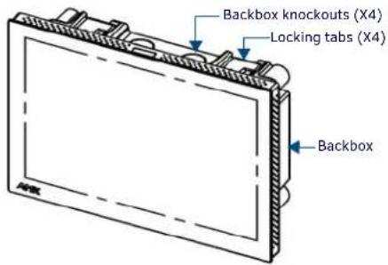
FIG. 3 MXD-1001 (LANDSCAPE)
- When installing the Backbox, make sure that the assembly is in the correct position and in the correct place. Once the locking tabs are extended and locked into place, removing the Backbox may be difficult without having access to the back of the wall or causing damage to the wall.
- In order to ensure a stable installation of the MXD-1001, the thickness of the wall material must be a minimum of .50 inches (1.27cm) and a maximum of .875 inches (2.22cm). The mounting surface should also be smooth and flat.
Installing the Backbox
For best results, use the included Installation Template (68-5968-03) to ensure proper placement. The template is marked on one side with directions for both landscape and portrait installations to ensure that the touch panel and Backbox are properly aligned. WARNING: Using the Installation Template to select the final placement of the Backbox is highly recommended. The outside edges of the template are the same dimensions as the touch panel, which allows you to troubleshoot possible conflicts with wall edges, doors, and other potential obstacles.
- Prepare the area by removing any screws or nails from the drywall before beginning the cutout process.
- After ensuring proper placement, cut out the mounting surface for the Backbox, using the (included) Installation Template as a guide. CAUTION: Making sure the actual cutout opening is slightly smaller than the provided dimensions is highly recommended. This provides a margin of error if the opening needs to be expanded. Too little wall material removed is always better than too much.
- Thread the incoming cables through the surface opening (FIG 4). Leave enough slack in the wiring to accommodate any re-positioning of the panel.
- Remove the Backbox knockouts and thread the incoming wiring through the knockout holes.
- Thread the incoming cables from the mounting surface opening and through the knockouts.
- Push the Backbox into the mounting surface. Insure that the locking tabs lie flush against the Backbox and that the Backbox goes freely into the opening.
- Extend the locking tabs on the sides of the Backbox by tightening the screws inside the box until snug. Apply enough pressure to the screw head to keep the box flush with the wall: this ensures that the locking tabs will tighten up against the inside of the wall. Note: The maximum recommended torque to screw in the locking tabs on the Backbox is 5 IN-LB [56 N-CM]. Applying excessive torque while tightening the tab screws, such as with powered screwdrivers, can strip out the locking tabs or damage the Backbox.
- For additional strength, #4 mounting screws (not included) may be secured via mounting circular holes located at the left and right sides of the MXD-1001 (FIG. 4). In order to prevent damage to the touch panel, make sure that these are flush with the Backbox.
![4X Installation Clamp for Wall Thickness .31 [12.0] to .98 [.25.0] HOLDING FLAMM 4X Knock-Outs Remove for Cable Routing as Needed #4 Screws](/content/2026/05/940181/images/1bc0c789053ecf789f866fbdab858dd87d615ecc132789dda345838a8a0286b0.jpg)
FIG. 4 MXD-1001 BACKBOX INSTALLATION (LANDSCAPE)
- Insert each connector into its corresponding location along the back of the device. To reach the RJ45 connector, gently pull it from beneath the electronics cover. Attach the Ethernet cable and gently push the connection back under the cover. Note: To facilitate connection of the RJ45 connector to the Ethernet cable, press the RJ45's cable into the RJ45 cable clip to hold it in a stable position. Make sure to remove the cable from the cable clip before continuing the rest of the installation.
- Test the incoming wiring by attaching the panel connections to their terminal locations and applying power. Verify that the panel is receiving power and functioning properly to prevent repetition of the installation. Note: Do not disconnect the connectors from the touch panel. The unit must be installed with the attached connectors before being inserted into the mounting surface. Remove power before continuing with the installation.
- Latch the panel onto the top hooks on the Backbox and push it down (Landscape) onto the bottom snaps or on the left side and push it to the right (Portrait) (FIG. 5). Press gently but firmly on the ends until the snaps "click" to lock it down.

FIG. 5 INSTALLING THE MXD-1001
WARNING: If you see a gap between the panel and the Backbox, or feel any binding while locking down the panel, stop immediately and verify that no cables or other items are in the way. Do not force the panel into position, as this can cause damage to the touch screen or the panel electronics.
- Reconnect the terminal Ethernet and USB to their respective locations on the Ethernet port.
Powering On/Off X Series G5 Panels
Modero X Series G5 touch panels may be powered on by touching and holding the Sleep button. To power off the panel, press and hold the Sleep button, and select Power Off on the on-screen menu (FIG. 6):

FIG. 6 SLEEP BUTTON - PRESS AND HOLD TO ACCESS POWER OFF/SETTINGS OPTIONS
Configuration and Programming
X Series G5 touch panels are equipped with a Settings menu that provides the ability to configure various features on the panels. To access the Settings menu, press and hold the Sleep button, and select Settings.
Note: Information on the Settings menu, panel configuration, and programming is provided in the Modero X Series G5 Programming Guide, available at www.amx.com.
Setting the Panel's Device Number and Device Name
- In the Settings menu, select NetLinx. This opens a password keypad.
- Enter the panel password into the keypad (the default is 1988) and select OK to access the NetLinx page.
- Press Device Number to open the NetLinx editing window.
- Enter a unique Device Number assignment for the panel and press OK.
- Enter a unique Device Name assignment for the panel and press OK.
Configuring the Panel's IP Address
These steps configure the panel to communicate with a network; it is still necessary to connect to the NetLinx Master (see Connecting to a NetLinx Master below).
Network Communication via DHCP
- In the Ethernet page, press DHCP/Static field to open the DHCP/Static window. Note that DHCP is the default setting.
- Select Host Name, enter the new host name
- Press OK to save changes.
Network Communication via Static Address
- In the Ethernet page, press DHCP/Static to open the DHCP/Static window.
- Select Static to open the Static IP window.
- Press any field to open a keypad or keyboard (depending on the field), and enter the appropriate network address information.
- Press OK to save your changes and return to the Ethernet page.
Connecting to a NetLinx Master
To establish the type of connection to make between the panel and the NetLinx Master:
1. In the NetLinx page, press Mode to choose the connection mode (URL, Listen or Auto):
CONNECTION MODES
| Mode Description Procedures | ||
| URL The | device connects to the target Master's IP address via a TCP connection. | 1) Select URL in the Mode menu.2) Enter the Master IP/URL, Master Port Number, and Username/Password (if required by the Master).3) Press OK to save changes. |
| Listen This mode allows the panel to "listen" for the Master's communication signals. Note that in this mode, the System Number and Master IP/URL fields are read-only. | 1) Select Listen in the Mode menu.2) Confirm the panel's IP address is on the Master's URL list (via NetLinx Studio).3) Press OK to save changes. Note: The Host Name (set on the Ethernet page), can be used to locate the panel on the Master (particularly useful for DHCP connections where the IP address can change). | |
| Auto Use this mode when both the panel and the NetLinx Master are on the same Subnet. | 1) Select Auto in the Mode menu.2) Enter the System Number and Username and Password (if applicable).3) Press OK to save changes. | |
- If password security is enabled on the target Master, enter the Username and Password:
a. Select Username to open the NetLinx window.
b. Enter the Username and Password required by the Master.
c. Press OK to save changes and return to the NetLinx page.
Related Software and Additional Documentation (at www.amx.com)
- Programming the Modero X Series G5 touch panels requires the use of the latest versions of NetLinx Studio and TPDesign5, both available to download at www.amx.com. Refer to the NetLinx Studio and TPDesign5 online help for information.
- For information on designing touch panel pages intended to optimize the Modero X Series G5 experience, refer to the G5 Considerations Guide.
- For additional information on the MXD-1001 panel, refer to the X-Series-G5 Touch Panels MXD/T-1001 & MXD/T-701 Instruction Manual.
- For detailed information on the Settings menu as well programming information and instructions on upgrading firmware, refer to the Modero X Series G5 Programming Guide.

Last Revised: 6/22/2015
© 2015 Harman. All rights reserved. Modero X and Modero X Series, AMX, AV FOR AN IT WORLD, and HARMAN, and their respective logos are registered trademarks of HARMAN. Oracle, Java and any other company or brand name referenced may be trademarks/registered trademarks of their respective companies.
AMX does not assume responsibility for errors or omissions. AMX also reserves the right to alter specifications without prior notice at any time. The AMX Warranty and Return Policy and related documents can be viewed/downloaded at www.amx.com.
3000 RESEARCH DRIVE, RICHARDSON, TX 75082 AMX.com | 800.222.0193 | 469.624.8000 | +1.469.624.7400 | fax 469.624.7153 AMX (UK) LTD, AMX by HARMAN - Auster Road, Clifton Moor, York, Y030 4GD United Kingdom • +44 1904-343-100 • www.amx.com/eu/
93-5968-48 REV: E
- MXD-1001 Installation
- Installing the MXD-1001 Into a Wall
- Installing the Backbox
- Powering On/Off X Series G5 Panels
- Configuration and Programming
- Setting the Panel's Device Number and Device Name
- Configuring the Panel's IP Address
- Network Communication via DHCP
- Network Communication via Static Address
- Connecting to a NetLinx Master
- Related Software and Additional Documentation (at www.amx.com)
Brand : AMX
Model : MXD-1001
Category : Wall touchscreen