
CD7SG1 - Cooker ARC - Free user manual and instructions
Find the device manual for free CD7SG1 ARC in PDF.


User questions about CD7SG1 ARC
0 question about this device. Answer the ones you know or ask your own.
Ask a new question about this device
Download the instructions for your Cooker in PDF format for free! Find your manual CD7SG1 - ARC and take your electronic device back in hand. On this page are published all the documents necessary for the use of your device. CD7SG1 by ARC.
USER MANUAL CD7SG1 ARC
60cm / 70cm / 90cm Gas Cooktop USER MANUAL

natural_image
Black-and-white photo of a bowl of soup with visible ingredients like vegetables, meatballs, and shredded vegetables (no text or symbols)ICD6SG4 60cm, 4 burner, cast iron trivets, s/steel
ICD9SG6 90cm, 5 burner, cast iron trivets, s/steel
CD6SG1 60cm, 4 burner, cast iron trivets, s/steel
CD7SG1 70cm, 5 burner, cast iron trivets, s/steel
CD9SG1 90cm, 5 burner, cast iron trivets, s/steel
GFC60 60cm, 4 burner, enamel trivets, s/steel

HOME APPLIANCES
For all product enquires, including warranty support,
please contact our Customer Care team
1800 444 357
or email
customercare@hapl.com.au
Dear Customer,
We thank you and congratulate you on granting us your preference, by purchasing one of our products. We are sure that this new appliance, manufactured with quality materials, will meet your requirements in the best possible way.
The use of this new equipment is easy. However, we invite you to read this booklet carefully, before installing and using the appliance. This booklet gives the right information on the installation, use and maintenance, as well useful advice.
THE MANUFACTURER
GENERAL NOTICE

We invite you to read this instruction booklet carefully, before installing and using the equipment. It is very important that you keep this booklet together with the equipment for any future consultation.
If this equipment should be sold or transferred to another person, make sure that the new user receives the booklet, so that he can learn how to operate the appliance and read the corresponding notice.
This is a Class 3 appliance.
This appliance complies with the following Directives:
EEC 90/396 (Gas)
EEC 73/23 e 93/68 (Low Voltage)
EEC 89/336 (Electromagnetic Compatibility)
EEC 89/109 (Contact with foods)
- The installation must be carried out by authorised personnel, in conformity with the regulations in force.
- This equipment has been designed to be used by adults.
- Therefore, make sure that children do not go near the equipment to play with it.
- This appliance is not intended for use by young children or infirm persons unless they have been adequately supervised by a responsible person to ensure that they can use the appliance safely.
- Before powering the equipment, check that it is properly adjusted for the type of gas at disposal (see the "installation" paragraph).
- Before carrying out the maintenance or cleaning the equipment, cut power supply off and make it cool down.
- Make sure that air circulates around the gas equipment. Insufficient ventilation produces a lack of oxygen.
- In case of an intense or prolonged use of the equipment, it may be necessary to improve aeration, for example by opening a window or increasing the mechanical suction power, if it exists.
- The products of combustion must be discharged outside through a suction hood or an electric fan (see the "installation" paragraph).
- For any possible operation or modification, apply to an authorized Technical Assistance Centre and demand original spare parts.
- Where this appliance is installed in marine craft or in caravans, it shall not be used as a space heater.
Servicing shall be carried out only by authorised personnel.
The product label, with the serial number, is sticked under the hob.
The manufacturer refuses all responsibility for possible damages to things or people, resulting from a wrong installation or from an improper, incorrect or unreasonable use of this equipment.
INSTRUCTIONS FOR THE USER

It is necessary that all the operations regarding the installation, adjustment and adaptation to the type of gas available are carried out by authorised personnel, in conformity with the regulations in force. The specific instructions are described in the booklet section intended for the installer.
USING THE BURNERS
The symbols silk-screen printed on the side of the knob indicate the correspondence between the knob and the burner.
Start-up without valves
Turn the corresponding knob anticlockwise up to the maximum position (large flame, fig. 1) and press the knob.
Using the burners
In order to obtain the maximum yield without waste of gas, it is important that the diameter of the pot is suitable for the burner potential (see the following table), so as to avoid that the flame goes out of the pot bottom (fig. 2).
Use the maximum capacity to quickly make the liquids reach the boiling temperature, and the reduced capacity to heat food or maintain boiling. All of the operating positions must be chosen between the maximum and the minimum ones, never between the minimum position and the closing point.
The gas supply can be interrupted by turning the knob clockwise up to the closing position. If there is no power supply, it is possible to light the burners with matches, setting the knob to the start-up point (large flame, fig. 1).
| BURNERS | Power (MJ/h) | ∅ of pots | |
| NG LPG | |||
| Auxiliary | 4.5 | 4.1 195 mm | |
| Semi-rapid | 6.0 | 6.0 | 195 mm |
| Rapid | 10.5 | 10.5 | 230 mm |
| Wok | 13.3 | 12.75 | 270 mm |
Notice
- When the equipment is not working, always check that the knobs are in the closing position (see fig.1).
- While cooking with fat or oil, pay the utmost attention as these substances can catch fire when overheated.
- Do not spray aerosols in the vicinity of the appliance while it is in operation.
- Do not store or use flammable liquids or items in the vicinity of this appliance.
- Do not place unstable or deformed pots on the
burner, so as to prevent them from overturning or overflowing.
- Make sure that pot handles are placed properly.
- When the burner is started up, check that the flameis regular and, before taking pots away, always lower the flame or put it out.
ABNORMAL OPERATION
Any of the following are considered to be abnormal operation and may require servicing:
- Yellow tipping of the hob burner flame.
- Sooting up of cooking utensils.
- Burners not igniting properly.
- Burners failing to remain alight.
- Burners extinguished by cupboard doors.
- Gas valves, which are difficult to turn.
- In case the appliance fails to operate correctly, contact the authorised service provider in your area.
CLEANING
Before any operation, disconnect the appliance from the electric grid.
It is advisable to clean the appliance when it is cold.
Enamelled parts
The enamelled parts must be washed with a sponge and soapy water or with a light detergent.
Do not use abrasive or corrosive products.
Do not leave substances, such as lemon or tomato juice, salt water, vinegar, coffee and milk on the enamelled surfaces for a long time.
Stainless steel parts
Stainless steel can be stained if it remains in contact with highly calcareous water or aggressive detergents for an extended period of time.
The stainless steel parts should also be cleaned with soapy water and then dried with a soft cloth.
Burners and racks
These parts can be removed to make cleaning easier. The burners must be washed with a sponge and soapy water or with a light detergent, wiped well and placed in their housing perfectly. Make sure that the flame-dividing ducts are not clogged. Check that the feeler of the safety valve and the start-up electrode are always perfectly cleaned, so as to ensure an optimum operation.
The racks can be washed in the dishwasher.
Gas taps
The possible lubrication of the taps must be carried out by authorised personnel, exclusively.
In case of hardening or malfunctions in the gas taps, apply to the Customer Service.
DO NOT MODIFY THIS APPLIANCE
INSTRUCTIONS FOR THE INSTALLER

IMPORTANT NOTICE:
THE OPERATIONS INDICATED BELOW MUST BE FOLLOWED BY AUTHORISED PERSONNEL EXCLUSIVELY, IN CONFORMITY WITH THE REGULATIONS IN FORCE.
THE MANUFACTURING FIRM REFUSES ALL RESPONSIBILITY FOR DAMAGES TO PEOPLE, ANIMALS OR THINGS, RESULTING FROM THE FAILURE TO COMPLY WITH SUCH PROVISIONS. THIS APPLIANCE SHALL BE INSTALLED ONLY BY AUTHORISED PERSONS AND IN ACCORDANCE WITH THE MANUFACTURER'S INSTALLATION INSTRUCTIONS, LOCAL GAS FITTING REGULATIONS, MUNICIPAL BUILDING CODES, ELECTRICAL WIRING REGULATIONS, AS 5601 - GAS INSTALLATIONS AND ANY OTHER STATUTORY REGULATIONS.
INSTALLATION
Installing the top
The appliance is designed to be embedded into heat-resistant pieces of furniture.
The walls of the pieces of furniture must resist a temperature of 75^ C besides the room one.
The equipment must not be installed near inflammable materials, such as curtains, cloths, etc. Make a hole in the top of the piece of furniture, with the dimensions indicated in fig.3, at a distance of at least 200 mm from the burner edge to the adjacent walls.
| MODELS | L (mm) | P (mm) |
| 60 cm & 70cm | 552mm | 470mm |
| 90cm | 830mm | 472mm |
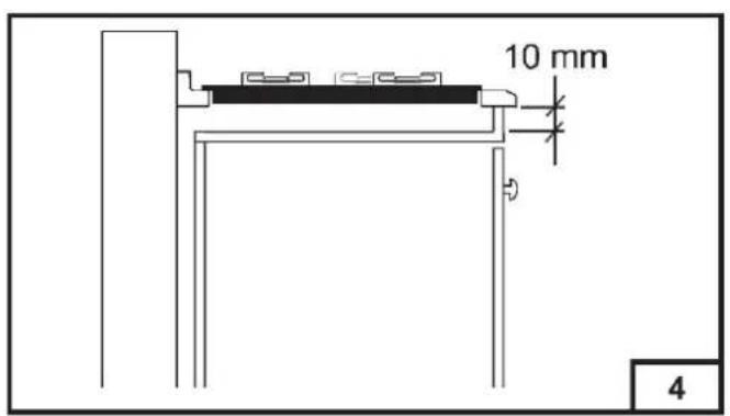
Any possible wall unit over the cook-top must be placed at a distance of at least 600 mm from the top. It is advisable to isolate the appliance from the piece of furniture below with a separator, leaving a depression space of at least 10 mm (fig. 4).
If the hob is going to be installed on the top of an oven, precautions must be taken to guarantee an installation in accordance with current accident prevention standards. Pay particular attention to the position of the electric cable and gas pipe: they must not touch any hot parts of the oven.
Moreover, if the hob is going to be installed on the top of a built in oven without forced cooling ventilation, proper air vents must be installed to guarantee an adequate ventilation, with the lower air entering with a cross section of at least 200cm ^2 , and the higher air exiting with a cross section of at least 60 cm ^2 .
Fastening the top
Every cook-top is equipped with a special washer. A set of hooks is also supplied for mounting the cook-top.
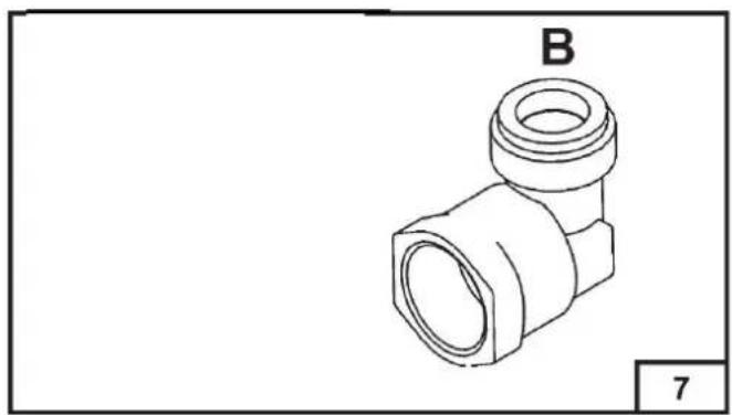
Depending on the type of mounting surface, the suitable type of mounting hook is supplied (hook A or hook B).
For the installation proceed as follows:
- Remove the racks and burners from the top.
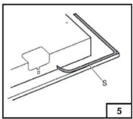
- Turn the appliance upside down and lay the washer S along the external border (fig. 5).
- Introduce and place the cook-top in the hole made in the piece of furniture, then block it with the V screws of the fastening hooks (fig.6 / 6A).
Installation room
This appliance is not provided with a device for exhausting the products of combustion.
Therefore, it is necessary to discharge these smokes outside.
The room where this appliance is installed must ave a natural air inflow, so as to ensure a regular gas combustion and room ventilation: the necessary air volume must not be lower than 20m ^3 .
Air must come from permanent openings made on the room walls that communicate with the outside.
The section of these openings shall correspond to at least 200 cm ^4 .
Gas Connection
Make sure that the appliance is adjusted for the gas type available (see the label under the appliance). Follow the instructions indicated in the chapter "gas transformations and adjustments" for the possible adaptation to different gases.
There are two ways to carry out the connection to the main gas line:
A. The hotplate can be connected with rigid pipe as specified in AS5601 table 3.1.
B. The hotplate can be connected with a Flexible Hose, which complies with AS/NZS 1869 (AGA Approved), 10mm ID, class B or D, no more than 1.2m long and in accordance with AS5601. Ensure that the Hose does not contact the hot surfaces of the hotplate, oven, dishwasher or other appliance that may be installed underneath or next to the hotplate. WARNING: Ensure that the hose
INSTRUCTIONS FOR THE INSTALLER
assembly is restrained from accidental contact with the flue or flue outlet of an underbench oven. The hose should not be subjected to abrasion, kinking or permanent deformation and should be able to be inspected along its entire length. Unions compatible with the hose fittings must be used and connections tested for gas leaks. The supply connection point shall be accessible with the appliance installed.
Please select the type which is correct for the supply concerned.
Once the installation is complete, check all connections for gas leaks with soap and water. DO NOT use a naked flame for detecting leaks. Ignite all burners both individually and concurrently to ensure correct operation of gas valves, burners and ignition. Turn gas taps to low flame position and observe stability of the flame for each burner individually and concurrently. When satisfied with the hotplate, please instruct the user on the correct method of operation. In case the appliance fails to operate correctly after all checks have been carried out, refer to the authorised service provider in your area.
Electric connection
The connection to the electric grid must be carried out by qualified personnel and in conformity with the regulations in force.
The voltage of the electric system must correspond to the value indicated in the label under the appliance. Make sure that the electric system is provided with an effective ground connection in compliance with the regulations and provisions of the law. Grounding is compulsory.
GAS TRANSFORMATIONS AND ADJUSTMENTS
Data Label
A duplicate Data Label is supplied to adhere in an accessible area next to the appliance.
This appliance is suitable for Natural Gas and Propane LPG; ensure that the available gas supply matches the Data Label.
When converting from Natural Gas to Propane LPG ensure that the NG regulator is removed and replaced with the Test Point Assembly. An approved gas regulator suitable for a supply pressure of 2.75kPa should be part of the gas tank supply and the test point pressure should be adjusted to 2.75kPa.
Replacing the nozzles
If the equipment is adjusted for a type of gas that is different from the one available, it is necessary to replace the burner nozzles.
The choice of the nozzles to replace must be made according to the table of the "technical characteristics" as enclosed.
Act as follows:
- remove the racks and burners.
- by means of a straight spanner L, unscrew the nozzle U (fig. 8) and substitute it with the corresponding one.
- tighten the nozzle strongly.
Adjusting the burners
The lowest flame point must always be properly adjusted and the flame must remain on even if there is an abrupt shift from the maximum to the minimum position.
If this is not so, it is necessary to adjust the lowest flame point as follows:
- start the burner up
- turn the tap up to the minimum position (small flame)
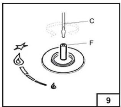
– remove the knob from the tap rod - introduce a flat-tip screwdriver C in the hole F of the tap (fig. 9) and turn the by-pass screw up to a proper adjustment of the lowest flame point.
Turndown screw set point:
Natural gas - 1/8 turn anti clockwise
Propane LPG - 1/12 turn anti clockwise
OVERALL COOKTOP DIMENSIONS
Maintenance Schedule
No regular maintenance is required for the hotplates except cleaning.
Replacing the power supply cable
If the power supply cable should be replaced, it is necessary to use a cable with a section of 3 × 0.75 mm^2 , type H05VV-F or H05RR-F, complying with the regulations in force.
The connection to the terminal board must be effected as shown in fig.10 - 10/A:
| brown cable L | (phase) |
| blue cable N | (neutral) |
| green-yellow cable | (ground) |


natural_image
Two cooking pots on a stove, one crossed out by a diagonal line (no text or symbols)
natural_image
Technical line drawing of a mechanical component with labeled parts S and 5 (no text or symbols beyond labels)

natural_image
Technical line drawing of a pipe fitting with labeled component B (no text or symbols beyond labels)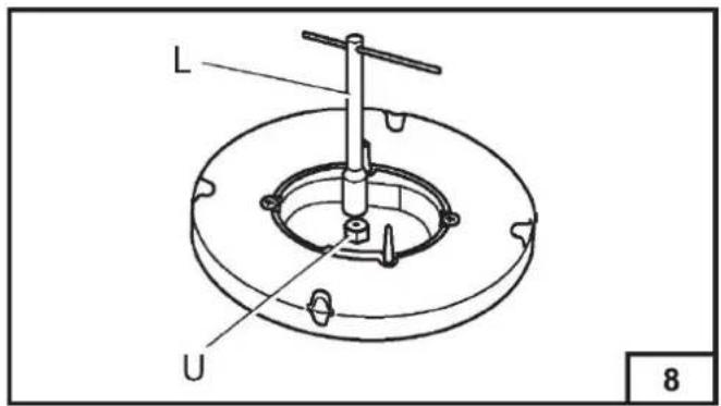


TECHNICAL CHARACTERISTIC TABLES
| BURNERS | GAS | NORMAL PRESSURE DIAMETER | TA PE BY PASS DIAMETER | NOMINAL HEAT INPUT (MJ/h) | |||
| KPa | 1/100 mm | 1/100 mm Max. Min. | |||||
| N^o | DESCRIPTION | ||||||
| 1 | RAPID | Propane LPG 2 Natural | 75 | 90 | 40 | 10.5 | 2.63 |
| 1.00 | 140 | Adjust. | 10.5 2 | 63 | |||
| 2 | SEMI-RAPID | Propane LPG Natural | 2.75 | 70 | 31 | 6.0 | 1.50 |
| 1.00 | 110 | Adjust. | 6.0 | 1.50 | |||
| 3 | AUXILIARY | Propane LPG Natural 1.00 | 2.75 | 55 | 27 | 4.1 | 1.08 |
| 90 | Adjust. | 4.5 | 1.13 | ||||
| 4 | Wok | Propane LPG Natural | 2.75 | 98 | 60 | 12.75 | 6.4 |
| 1.00 | 170 | Adjust. | 13.3 | 7.0 | |||
The manufacturing firm refuses all responsibility for any possible imprecision in this booklet, due to misprints or clerical errors. It reserves the right to make all the changes that it will consider necessary in its own products, without effecting the essential characteristics of functionality and safety.
7KLV□SDJH□KDV□EHHQ□OHIW□EODQN□LQWHQWLRQD00
7KLV□SDJH□KDV□EHHQ□CHI□E□DQN□LQWHQWLRQD00
7KLV□SDJH□KDV□EHHQ□OHIW□EODQN□LQWHQWLRQD00


- 60cm / 70cm / 90cm Gas Cooktop USER MANUAL
- Dear Customer,
- GENERAL NOTICE
- INSTRUCTIONS FOR THE USER
- USING THE BURNERS
- Start-up without valves
- Notice
- ABNORMAL OPERATION
- CLEANING
- Enamelled parts
- Stainless steel parts
- Burners and racks
- Gas taps
- INSTRUCTIONS FOR THE INSTALLER
- IMPORTANT NOTICE:
- INSTALLATION
- Installing the top
- Fastening the top
- Installation room
- Gas Connection
- Electric connection
- GAS TRANSFORMATIONS AND ADJUSTMENTS
- Data Label
- Replacing the nozzles
- Adjusting the burners
- OVERALL COOKTOP DIMENSIONS
- Maintenance Schedule
- Replacing the power supply cable
Brand : ARC
Model : CD7SG1
Category : Cooker