
VAM500FCVE - Heat exchanger DAIKIN - Free user manual and instructions
Find the device manual for free VAM500FCVE DAIKIN in PDF.


| Brand | Daikin |
| Model | VAM500FCVE |
| Product Type | Total Heat Exchanger (HRV) |
| Installation Type | Ceiling mounted duct type |
| Modes | Heat Exchange mode, Bypass mode, Automatic mode, Fresh Up mode |
| Airflow Rate Settings | Low, High, Low Fresh Up, High Fresh Up |
| Air Filter Type | Long life filter (replaceable) |
| Heat Exchange Element Cleaning | Use vacuum cleaner with brush; do not wash with water |
| Air Filter Cleaning Frequency | At least every 2 years (general office use) |
| Remote Controller | BRC301B61 (optional), also compatible with VRV remote controllers |
| Operation Temperature Range | -15°C to 50°C (ambient) |
| Maximum Humidity | 80% RH or less |
| Safety Features | Automatic shut-off, filter cleaning indicator, error code display |
| Duct Connection Flanges | Included (EA, OA, RA, SA ports) |
| Maintenance Access | Maintenance cover for filter and heat exchange element removal |
| Spare Parts Available | Replacement air filters |
| Compliance | CE, RoHS (implied) |
| Weight | Approximately 25 kg (estimate) |
Frequently Asked Questions - VAM500FCVE DAIKIN
User questions about VAM500FCVE DAIKIN
0 question about this device. Answer the ones you know or ask your own.
Ask a new question about this device
Download the instructions for your Heat exchanger in PDF format for free! Find your manual VAM500FCVE - DAIKIN and take your electronic device back in hand. On this page are published all the documents necessary for the use of your device. VAM500FCVE by DAIKIN.
USER MANUAL VAM500FCVE DAIKIN
Total Heat Exchanger HRV (Heat Reclaim Ventilation) (Ceiling mounted duct type)
VAM350FC
VAM500FC
VAM650FC
VAM800FC
VAM1000FC
VAM1500FC
VAM2000FC
1
2
3
natural_image
Simple line drawing of a vacuum cleaner next to a notepad (no text or symbols)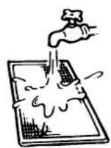
4
natural_image
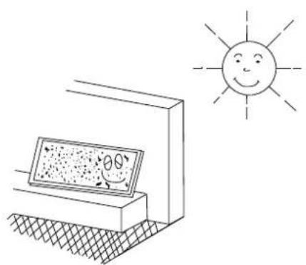
Simple line drawing of a solar panel with a smiling sun and angle markings (no text or symbols)5
natural_image
Illustration of a hand inserting a tool into a grid-patterned building (no text or symbols)6
7
Contents Page
一
Safety cautions.... 1
Names of parts....2
Operation 2
Maintenance....4
Trouble and countermeasure 5
Disposal requirements 6
Thank you for purchasing this Daikin HRV.
The original instructions are written in English. All other languages are translations of the original instructions.

HRV – Heat Reclaim Ventilation
Before using the DAIKIN HRV, be sure to read this operation manual thoroughly. If you have any problems or there is a malfunction, please refer to this operation manual. Please keep this manual for your future reference whenever you do not understand how to use it when something is wrong with the unit during the operation.
Safety cautions
Read the following cautions carefully and use your equipment properly.
Meaning of warning and caution symbols:

WARNING Failure to follow these instructions properly may result in personal injury or loss of life.

CAUTION Failure to observe these instructions properly may result in property damage or personal injury, which may be serious depending on the circumstances.
NOTE

These instructions will ensure proper use of the equipment.
Be sure to follow these important safety cautions.
Keep these warning sheets handy so that you can refer to them if needed.
Also, if this equipment is transferred to a new user, make sure to hand over this user's manual to the new user.

WARNING + ELECTRIC SHOCK

■ Before servicing the unit always shut off power, otherwise electric shock may occur.
■ Never inspect or service the unit by yourself.
Ask a qualified service person to perform this work.
■ Always use the air filter.
If the air filter is not used, heat exchange elements will be clogged, possibly causing poor performance and subsequent failure.
■ Do not change operations suddenly. It can result not only in malfunction but also failure of switches or relays in the body.
This appliance is intended to be used by expert or trained users in shops, in light industry and on farms, or for commercial use by lay persons.
This appliance is not intended for use by persons (including children) with reduced physical, sensory or mental capabilities, or lack of experience and knowledge, unless they have been given supervision or instruction concerning use of the appliance by a person responsible for their safety. Children should be supervised to ensure that they do not play with the appliance.
■ Do not use an HRV or an air suction/discharge grille in the following places:
- Places such as machinery plants and chemical plants where gas, which contains noxius gas or corrosive components of materials such as acid, alkali, organic solvent and paint, is generated.
- Places where combustible gas leakage is likely. Such gas can cause fire.
- Places such as bathrooms subjected to moisture. Electric leak or electric shock and other failure can be caused.
- Places subjected to high temperature or direct flame. Avoid a place where the temperature near the HRV unit and the air suction/discharge air grille exceeds 50°C. If the unit is used at high temperature, deformed air filter and heat exchange element or burned motor result. Unit ambient temperature conditions should be between -15°C and 50°C (80% relative humidity or less)
- Places subjected to much carbon black. Carbon black attaches to air filter and heat exchange element, disabling them.
Names of parts
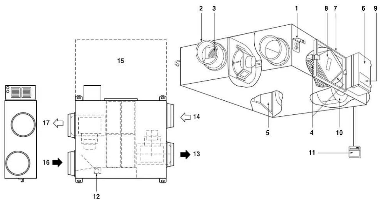
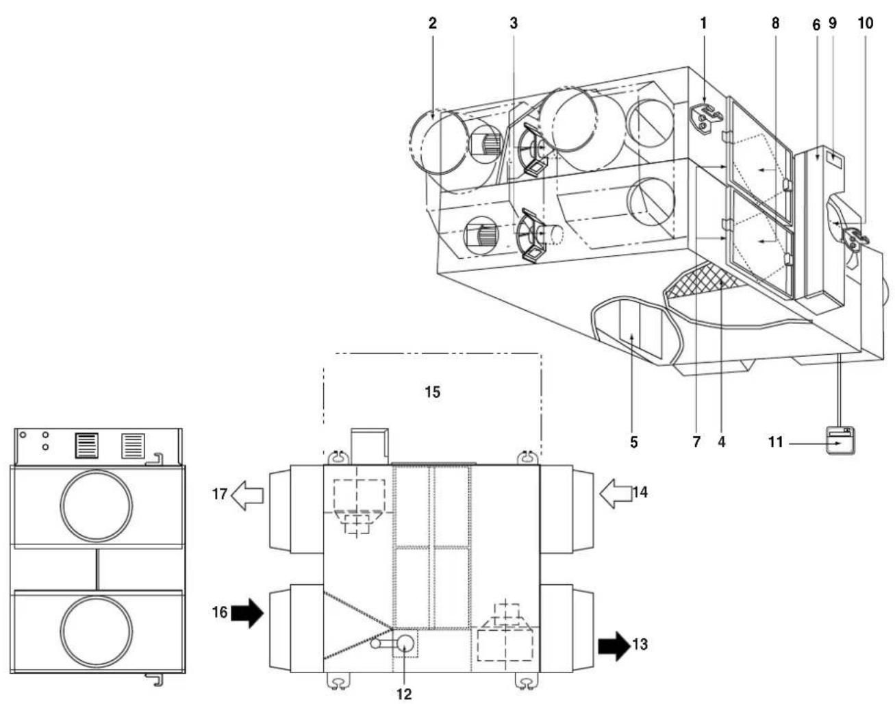
Refer to figure 1 (models VAM350\~1000F) and figure 2 (models VAM1500\~2000F)
1 Ceiling hook
2 Duct connection flange
3 Exhaust fan
4 Air filter (Long life filter)
5 Damper
6 Switch box
7 Maintenance cover
8 Heat exchange elements
9 Name plate
10 Air supply fan
11 Remote controller (Option parts)
12 Damper motor
13 EA (Exhaust air) (Exhaust air to outdoor)
14 OA (Outdoor air) (Fresh air from outdoor)
15 Maintenance space for the air filters, the heat exchange elements and Switch box
16 RA (Return air) (Exhaust air from room)
17 SA (Supply air) (Feed air to room)
Operation
Explanation for systems
This product is operated differently depending on the system configuration.
For the operation of the remote controller for indoor unit and of the centralized controller, refer to the instruction manual provided with each unit.
Operation for each system
Independent system
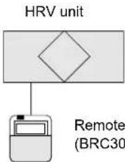
flowchart
graph TD
    A["HRV unit"] --> B["Remote (BRC30)"]
Operation method
The remote controller turns the HRV unit on and off (refer to the section "Operation with the remote control exclusively for Air conditioning operation HRV units (BRC301B61)" on page 3).
Combined operation system with VRV systems and Sky-air series
Combination 1
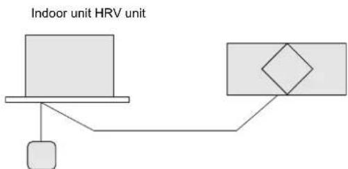
flowchart
graph TD
    A["Indoor unit HRV unit"] --> B["Device"]
    B --> C["Sensor"]
    C --> D["Ground"]
Remote controller for indoor unit
Operation method
The remote controller for air conditioner turns the air conditioner and HRV unit on and off.
If only the HRV unit is used without operating the air conditioner, set the unit in the "VENTILATION mode. (Refer to the section "Operating the HRV unit using the remote controller of the VRV-system air conditioner" on page 4)
Combination 2
Operation method
The ON/OFF and timer operation can not be performed using the HRV remote controllers.
(The indication of centralized control "appears on the display.)
Other operations can be performed using the HRV remote controllers.
Starting and stopping operations of the indoor unit and the HRV unit can be performed using the indoor remote controllers.
(Refer to the section "Operation with the remote control exclusively for Air conditioning operation HRV units (BRC301B61)" on page 3)
Centralized system
Centralized controller HRV unit
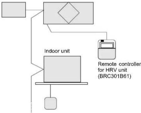
flowchart
graph TD
    A["Indoor unit"] --> B["Remote controller for HRV unit (BRC301B61)"]
    B --> C["Indoor unit"]
    C --> D["Indoor unit"]
    D --> E["Indoor unit"]
    E --> F["Indoor unit"]
    F --> G["Indoor unit"]
Remote controller for indoor unit
Operation method
When the HRV remote controllers is not connected, the Centralized controller controls the operation of the HRV unit. (Refer to the section "Independent operation of the HRV unit using the centralized controller (DCS302C51)" on page 4)
When the HRV remote controllers is connected, operation can be started and stopped using the centralized controller or the indoor and the HRV remote controllers.
During the indication of centralized control "appears on the display, the ON/OFF and timer operation may not be possible with the HRV remote controllers.
Other operations can be performed using the HRV remote controllers. (Refer to the next sections)
Operation with the remote control exclusively for Air conditioning operation HRV units (BRC301B61)
For non-independent systems, starting/stopping operation and timer operation may not be possible.
Use the air conditioner remote control or the Centralized controller in such cases.
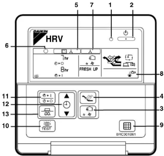
BRC301B61: Remote controller for HRV
- Operation lamp
This pilot lamp (red) lights up while the unit is in operation.
- Operation/Stop button
When pushed once, the unit starts operating.
When pushed again, the unit stops.
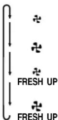
- Air flow rate changeover button
Air flow rate can be changed over to "♣" Low mode or
“♣” High mode,
“♣ FRESH UP” Low FRESH UP mode,
“ FRESH UP” High FRESH UP mode.
For "FRESH UP" operation
When this indication does not show: The volume of outdoor air supplied into the room and that of the room air exhausted outdoors is equivalent.
For "FRESH UP" operation
- If it is set to "Fresh up air supply": The volume of outdoor air supplied into the room is larger than that of room air exhausted outdoors.
(This operation prevents the odor and moisture from kitchens and toilets from flowing into the rooms.)
This is the factory setting.
- If it is set to "Fresh up air exhaust": The volume of room air exhausted outdoors is larger than that of outdoor air supplied into the room.
(This operation prevents the hospital odor and floating bacteria from flowing out to the corridors.)
To change the setting, refer to chapter "Local settings" in the installation manual.
- Ventilation mode changeover button
“(☐)” Automatic mode.
The temperature sensor of the unit automatically changes the ventilation of the unit in Bypass mode and Heat Exchange mode.
" Heat Exchange mode.
In this mode, the air passes through the heat exchanger element to effect Total Heat Exchanging ventilation.
" Bypass mode.
In this mode, the air does not pass through the heat exchange element but by passes it to effect Bypass ventilation.
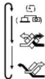
- Indication of operation control method:
When the operation of HRVs are linked with the air conditioners, this indication may be shown.
While the indication is shown, the ON/OFF of HRVs cannot be operated by the HRV remote controller.
- Indication of operation standby:
It indicates the precooling/preheating operation. This unit is at stop and will start operation after the precooling/preheating operation is over.
Precooling/preheating operation means the operation of HRVs is delayed during the startup operation of linked air conditioners, for example before the office hours.
During this period the cooling or heating load is reduced to bring the room temperature to the set temperature in a short time.
- Indication of centralized control:
When a remote controller for air conditioners or devices for centralized control are connected to the HRVs, this indication may show.
When this indication appears on the display, the ON/OFF and timer operation may not be possible with the HRV remote controllers.
- Indication of air filter cleaning
When the indication " 🔍" appears on the display, clean the filter.
-
Filter signal reset button
-
Inspection button
This button is to be used only for service. It is not to be used normally.
How to operate with timer
- Schedule timer button " 0+1 / 0"
This button enables or disables the schedule timer.
-
Push the time adjust button " ▲" to set the time.
-
Push the programming button "☐" / "◇"
Then, the reservation is finished.
Operating the HRV unit using the remote controller of the VRV-system air conditioner
Please read the manual supplied with the remote controller for more detailed instructions (optional controllers: BRC1D52 or BRC1E52).
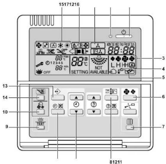
BRC1D52: Remote controller for VRV
1 Operation lamp
2 Operation/stop button
3 Fan speed icon
4 Air filter cleaning time icon
5 Element cleaning time icon
6 Air conditioner fan speed button
7 Air filter cleaning time icon reset button
8 Air conditioner operation mode
9 Inspection button
10 Air flow rate changeover button
11
12 See "How to operate with timer" on page 3
13
14 Ventilation mode button
15 Operation mode display
16 Defrost/hotstart mode icon
17 Indication of centralized control
When the VRV-system air conditioner is connected with the HRV unit with a direct duct, the remote controller of the air conditioner cannot be used to select the VENTILATION mode. To use the HRV unit without operating the air conditioner, set the air conditioner in the FAN VENTILATION mode and select the low fan speed.
■ Every time the operation mode selector is pressed, the operation mode display changes as shown below.
Example
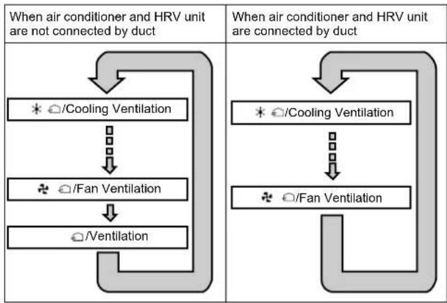
flowchart
graph TD
    A["When air conditioner and HRV unit are not connected by duct"] --> B["* /Cooling Ventilation"]
    B --> C["↓"]
    C --> D["✿ /Fan Ventilation"]
    D --> E["○/Ventilation"]
    F["When air conditioner and HRV unit are connected by duct"] --> G["* /Cooling Ventilation"]
    G --> H["↓"]
    H --> I["✿ /Fan Ventilation"]
When the ☐ "FILTER" indication appears on the display, clean the filter of the HRV unit. (Refer to the section "Maintenance" on page 4)
■ For adjusting the installation settings, contact your installer.
Independent operation of the HRV unit using the centralized controller (DCS302C51)
■ After selecting the zone where only the HRV operation is desired, press the operation mode selector and select " VENTILATION. The HRV unit can then be operated independently from the air conditioner.
When the ☐ "FILTER" indication appears on the display, clean the filter of the HRV unit. (Refer to the section "Maintenance" on page 4)
Maintenance
(for a qualified service person only)

WARNING
■ Be sure to turn off the OPERATION switch and disconnect the power.
■ Only a qualified service person is allowed to perform maintenance.
During operation, never check or clean the HRV. It may cause electrical shock and it is very dangerous to touch the rotating part.
Maintenance for the air filter
Cleaning frequency
At least once every two years (for general office use) (clean more frequently if necessary.)
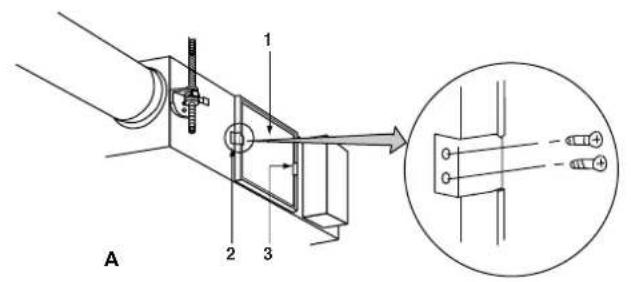
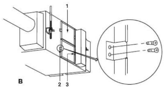
1 Go into the ceiling through the inspection hole, remove binding metal of maintenance cover and take it off. (Refer to figure 3 (A = Models VAM350\~1000F, B = Models VAM1500\~2000F))
1 Maintenance cover
2 Binding metal
3 Hanging metal
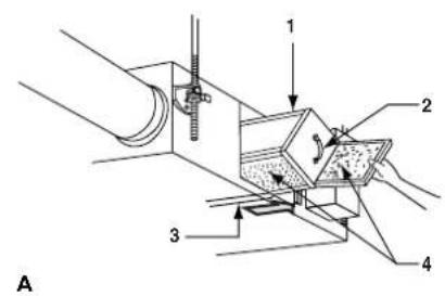
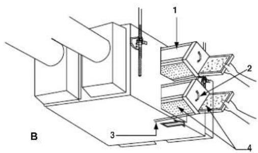
2 Take out the heat exchange elements from the unit body. (Refer to figure 4 (A = Models VAM350\~1000F, B = Models VAM1500\~2000F))
1 Heat exchange element
2 Handle
3 Rail
4 Filter
3 To clean the air filter, lightly pat it with hand or remove dust with a vacuum cleaner. If excessively dirty, wash it in water. (Refer to figure 5)
4 If the air filter is washed, remove water completely and allow to dry for 20 to 30 minutes in the shade. When dried completely, install the air filter back in place. (Refer to figure 6)
5 Install the maintenance cover securely in place. Maximum allowed torque on the screws is 2,17 Nm.

CAUTION
■ Do not wash the air filter in hot water.
■ Do not dry the air filter over a fire.
■ Do not subject the air filter to direct sunlight.
■ Do not use organic solvent such as gasoline and thinner on the air filter.
■ Be sure to install the air filter after servicing.
(Missing air filter causes clogged heat exchange element.)
Replacement air filters are available.
Maintenance for the heat exchange element
Cleaning frequency
At least once every two years (for general office use) (clean the element more frequently if necessary.)
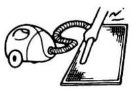
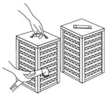
1 Use a vacuum cleaner to remove dust and foreign objects on the surface of the heat exchange element. (Refer to figure 7)
- Use the vacuum cleaner equipped with a brush on the tip of the suction nozzle.
- Lightly contact the brush on the surface of the heat exchanging element when cleaning.
(Do not crush the heat exchange element while cleaning.)
2 Install the air filter securely in place.
3 Put the heat exchange element on the rail and insert it securely in place.
4 Install the maintenance cover securely in place.

CAUTION
Never wash the heat exchanger element with water.
Trouble and countermeasure
If your unit does not operate properly, check the following items
| Conditions Causes Corrective actions | ||
| The unit does not operate at all. | Check if there is a power failure. | After power has been restored, start operation again. |
| Check if the fuse has blown or breaker has worked. Change the fuse or set the breaker. | ||
| Check if the indication of operation control method on remote controller (BRC301B61) is shown. | This is normal. Operate the unit using the air conditioner remote control or centralized controller. (Refer to "Operation" on page 2) | |
| Check if the indication of operation stand by on remote controller (BRC301B61) is shown. | It indicates the precooling/preheating operation. This unit is at stop and will start operation after the precooling/preheating operation is over. (Refer to "Operation" on page 2) | |
| Amount of discharged air is small and the discharging sound is high. | Check if the air filter and heat exchange element are clogged. | Refer to "Maintenance" on page 4. |
| Amount of discharged air is large and so is the sound. | Check if the air filter and heat exchange element are installed. | Refer to "Maintenance" on page 4. |
If the following occurs, consult the dealer where the unit was purchased
List of malfunction codes of remote controller of the HRV-system air conditioner
| Operation lamp | Inspection indicator | Unit No. | Malfunction code | Description |
| On | Off | Blinking | 64 | Indoor air thermistor malfunction |
| On | Off | Blinking | 65 | Outdoor air thermistor malfunction |
| On | Off | Blinking | 6A | Damper-related malfunction |
| Blinking | Blinking | Blinking | 6A | Damper-related malfunction + thermistor |
| Blinking | Blinking | Blinking | A6 | Locked rotor |
| Blinking | Blinking | Blinking | C1 | Fan communication error |
| Blinking | Blinking | Blinking | U5 | Transmission error between the unit and remote controller |
| Off | Blinking | Off | U5 | Printed circuit board error or setting error of remote controller |
| Off | Blinking | Off | U8 | Transmission error between main remote controller and sub remote controller |
| Off | Blinking | Blinking | UA | Wrong remote controller installed |
| On | Off | On | UC | Repeated central address |
| Blinking | Blinking | Blinking | UE | Transmission error between the unit and centralized controller |
In case of malfunction with the code in white letters on black background, the unit still operates.
However, be sure to have it inspected and repaired as soon as possible.
Disposal requirements
Dismantling of the unit must be done in accordance with relevant local and national legislation.

natural_image
Blank grid paper with no text, numbers, or symbols

natural_image
Blank grid paper with no text, numbers, or symbols- Contents Page
- HRV – Heat Reclaim Ventilation
- Safety cautions
- WARNING + ELECTRIC SHOCK
- Names of parts
- Operation
- Explanation for systems
- Independent system
- Combined operation system with VRV systems and Sky-air series
- Combination 1
- Combination 2
- Operation method
- Centralized system
- Operation with the remote control exclusively for Air conditioning operation HRV units (BRC301B61)
- Operating the HRV unit using the remote controller of the VRV-system air conditioner
- Independent operation of the HRV unit using the centralized controller (DCS302C51)
- Maintenance
- (for a qualified service person only)
- WARNING
- Maintenance for the air filter
- Cleaning frequency
- CAUTION
- Trouble and countermeasure
- If the following occurs, consult the dealer where the unit was purchased
- Disposal requirements
Brand : DAIKIN
Model : VAM500FCVE
Category : Heat exchanger