
D24281B-2NA4-E - Video recorder Lorex - Free user manual and instructions
Find the device manual for free D24281B-2NA4-E Lorex in PDF.


| Product Type | 8-channel 1080p HD DVR Video Recorder |
| Model | D24281B-2NA4-E |
| Dimensions (W × D × H) | 12.9 × 9.6 × 2.1 inches (328 × 245 × 53 mm) |
| Weight (without HDD) | 2.75 lbs (1.26 kg) |
| Power Supply | 12V DC, 2A adapter (included), consumption <15W (excl. HDD) |
| Video Compression | H.265 / H.264 |
| Recording Resolution | 1080p, 720p, 960H, D1, CIF |
| Recording Frame Rate | 1080p@15fps (NTSC); 720p/960H/D1/CIF@25/30fps (PAL/NTSC) |
| Hard Drive Bay | 1 SATA port, supports up to 16 TB |
| Video Outputs | 1 × HDMI, 1 × VGA |
| Audio | 1 × RCA Audio In, 1 × RCA Audio Out |
| Network Interface | 10/100 Base-TX RJ45 Ethernet |
| USB Ports | 2 × USB 2.0 (front and back) |
| Smart Motion Detection | Person and Vehicle detection on all channels |
| Active Deterrence Support | Yes (compatible cameras required) |
| Smart Home Compatible | Amazon Alexa, Google Assistant, Apple TV, Chromecast |
| Remote Viewing App | Lorex Home for iOS and Android |
| Backup Media | USB flash drive or USB HDD (formats: FAT32, NTFS) |
| Playback | Up to 4 channels simultaneously, variable speed up to 16x |
| Operating Temperature | 14°F to 131°F (-10°C to 55°C) |
| Humidity | 10% to 90% RH |
| Package Contents | DVR, power adapter, Ethernet cable, USB mouse, HDMI cable |
| Safety & Maintenance | Use surge protector; clean with damp cloth; no user-serviceable parts |
| Warranty | See lorex.com/warranty for details |
Frequently Asked Questions - D24281B-2NA4-E Lorex
User questions about D24281B-2NA4-E Lorex
0 question about this device. Answer the ones you know or ask your own.
Ask a new question about this device
Download the instructions for your Video recorder in PDF format for free! Find your manual D24281B-2NA4-E - Lorex and take your electronic device back in hand. On this page are published all the documents necessary for the use of your device. D24281B-2NA4-E by Lorex.
USER MANUAL D24281B-2NA4-E Lorex
Package contents and dimensions....1
Back panel overview....2
Setup
Step 1: connect cameras....3
Step 2: connect router......5
Step 3: connect mouse....6
Step 4: connect monitor/TV....7
Step 5: connect power....8
Step 6: Lorex Setup Wizard....9
Using the mouse....10
Using the quick menu....11
Motion and smart motion detection....12
Using deterrence features....13
Changing the recorder's output resolution....17
Playback and search....18
Backup....19
Remote viewing
Before you start....20
Connect to the app....21
Lorex Home app live view....22
Package contents and dimensions
• 1080p HD Security DVR
- Power adapter
- Ethernet cable
- USB mouse
- HDMI cable

Back panel overview

Note: The 8 channel DVR recorder in this guide is for illustration only. Your recorder may appear different, with all the same ports in different locations.

-
Video Inputs: Connect cameras*
-
VGA Port: Connect monitor*
-
Audio In/Out: Connect microphone/speaker*
-
USB Port: Connect mouse or USB stick*
-
HDMI port: Connect monitor*
-
Power Port: Connect power
-
LAN Port: Connect router* 9. Power Switch: Power on/off
-
RS-485: Connect Pan-Tilt-Zoom cameras*
*Not included/sold separately.
Setup step 1 — Connect cameras

IMPORTANT: Test your cameras prior to selecting a permanent mounting location by rarely connecting the cameras and cables to your DVR.
To connect cameras directly to the DVR:
- Connect the extension cable's male power head and BNC connector to the camera.
- Then connect the other end of the BNC connector to a video input on your DVR.
- Connect the female power head to the included power adapter.
![graph LR A["Power adapter"] --> B["Switch"] C["BNC connector Video input"] --> B B --> D["Output"] style A fill:#f9f,stroke:#333 style C fill:#f9f,stroke:#333 style D fill:#ccf,stroke:#333](/content/2026/05/938670/images/017aac2144a14d25913f9f72c10666df953270c8c48d16bf08f5af1211cc0008.jpg)

Notes:
- The extension cable must be a single stretch of cable between the recorder and camera. You cannot connect multiple extension cables to each other.
- This guide covers connecting cameras to your security recorder only. For full instructions on installing your cameras and mounting tips, please refer to your camera's documentation at lorex.com.
Setup step 2 — Connect router
Connect the recorder to your router using the included Ethernet cable.



Note: To receive automatic firmware updates and access your system remotely with mobile apps, a high speed Internet connection is required. A minimum upload speed of 3.5Mbps is required. All other system features can be used without an Internet connection.
Setup step 3 — Connect mouse
Connect the included USB mouse to the USB port on the recorder.

To copy your video recordings and to perform a firmware upgrade, connect a USB stick or flash drive to the USB port on the front panel of the recorder.

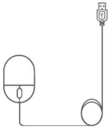
Setup step 4 — Connect monitor/TV
Connect the recorder to a monitor/TV using the included HDMI cable or a VGA cable (not included).

Note: To optimize picture quality, set the recorder's video output to match the resolution of your monitor. See 'Changing the recorder's output resolution' page 17 for details.

Setup step 5 — Connect power
Connect the recorder to a nearby outlet using the included power adapter.
Then flip the power switch on.
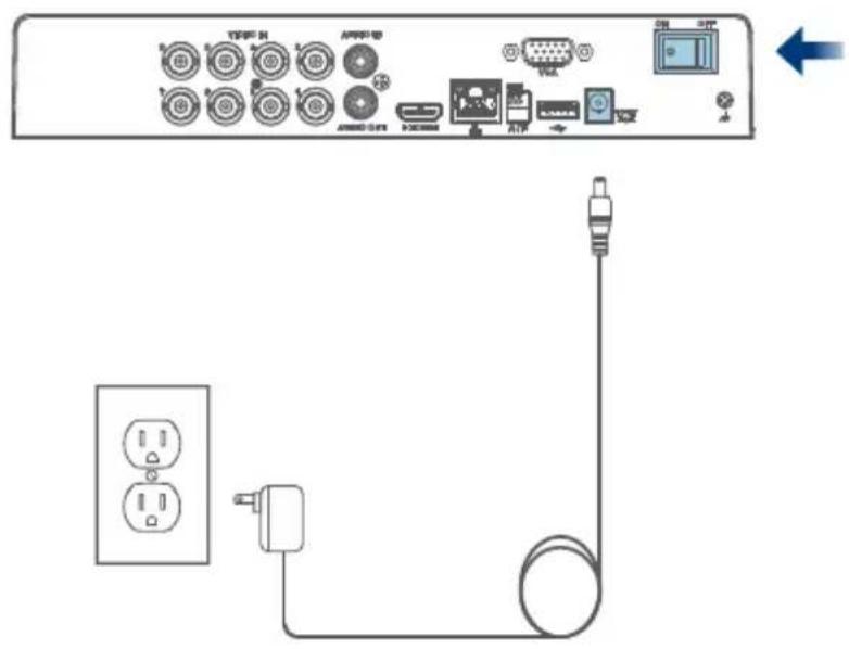
Setup step 6 — Lorex Setup Wizard
When you first power up your recorder, the Lorex Setup Wizard will begin. The Wizard will help you to configure core system settings.
You will also create a secure password. This password will be used to login to your system and connect to the Lorex Home app.
Record your password below:

Quick access to system information
To quickly open a window that displays vital system information such as device ID, model number, firmware version, and IP address:
- Tap the information button on the front panel of the recorder, or
• Right-click to open the Quick Menu and then click i Info
Using the mouse

- During split-screen display: Click an individual channel to view in full-screen. Click again to return to the split-screen display mode.
- While navigating menus: Click to open a menu option.
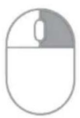
- During live view: Click • During live view: Use anywhere on the screen the scroll wheel to zoom to open the Quick Menu. in/out.
• While navigating menus: Click to exit menus.

Using the quick menu
Right-click anywhere on the live viewing screen to open the Quick Menu.
| Main Menu |
| Playback |
| Pan/Tilt/Zoom |
| View 1 |
| View 4 |
| View 8 |
| View 9 |
| Previous Channel(s) |
| Next Channel(s) |
| Info |
| Sequence |
| Disable Beep |
| Manual Record |
| Image Settings |
- Main Menu: Open the Main Menu.
• Playback: Search and playback recordings.
• Pan/Tilt/Zoom: Control PTZ cameras.*
• View 1-9: Select camera/live display view.
• Previous/Next Channel(s): View the previous or next channel(s).
• Info: View system information.
• Sequence: Start or stop sequence mode.
- Disable Beep:
Temporarily disable all current audible warnings.
- Manual Record: Open manual recording controls.
• Image Settings: Adjust camera color and image settings.
*Compatible with select cameras only. Visit lorex.com/compatibility for details.
Motion and smart motion detection
Set preferences for motion including setup of person and/or vehicle detection.
To configure motion and smart motion detection settings:
- From the camera's live view, right-click and then click Main Menu.
- Enter the system user name (default: admin) and password.
- Click EVENTS > Event Settings > Motion Detection.
- Configure the following:
a. Select a connected smart motion detection camera.
b. Check Enable.
c. Click Setup > Area to set the active areas.
d. Click Setup > Schedule to set the weekly schedule.
e. Set preferences for how the system reacts to motion.
f. Click Smart Motion Detection to enable person or vehicle detection (see next page).

Motion and smart motion detection
g. Check Enable.
h. Select a Sensitivity level (a higher sensitivity value will detect smaller objects than a low value).
i. Check Person and/or Vehicle to disable or enable each type of smart detection.
j. Click OK, then Apply to save.

Using deterrence features
Set preferences for automatic warning light on deterrence cameras. For a complete list of compatible cameras, visit lorex.com/compatibility.
To configure deterrence settings:
- From the camera's live view, right-click and then click Main Menu.
- Enter the system user name (default: admin) and password.
- Click EVENTS > Event Settings > Deterrence.
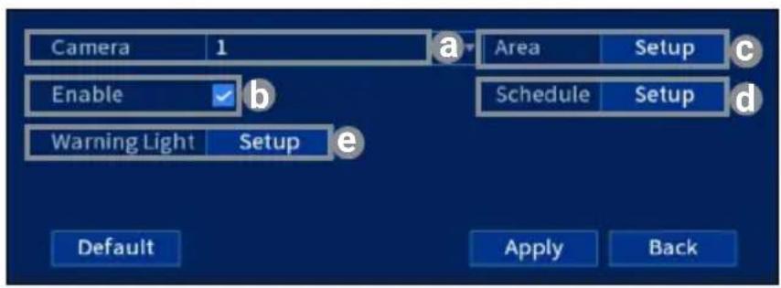
- Configure the following:
a. Select a connected deterrence camera.
b. Check Enable.
c. Click Setup > Area to set an active area for automatic deterrence.
d. Click Set > Schedule to set the weekly schedule for automatic deterrence.
e. Click Setup > Warning Light to configure preferences (see next page).
Using deterrence features
To configure warning light settings:
f. For Duration, choose how long the warning light will stay on when motion is detected.
g. Select Warning Light for a solid white light, or Strobe for a flashing light.
h. If you select strobe, set how quickly the light will flash under Strobe Frequency.
i. Click Apply to save.

To manually activate the warning light and/or siren features:
Prerequisite: Connect to your recorder using the Lorex Home app, see 'Remote viewing' page 20.
- Launch the Lorex Home app and tap your DVR to view connected channels.
- Tap a connected smart deterrence camera to open it in single-channel view.
- Tap to activate the warning light, or tap to activate the siren.
To activate deterrence features on all connected cameras, push and hold the front panel panic button on the DVR for 3 seconds.


Note: For full instructions on using the deterrence features, refer to the DVR's manual on your product page at lorex.com.
Changing the recorder's output resolution
To ensure the best possible picture quality, set the recorder's output resolution to match the highest resolution supported by your monitor (maximum resolution of 1080p).

IMPORTANT: If you need to switch the monitor, make sure you set the recorder to an output ion supported by the new monitor before switching.
To change the recorder's output resolution:
- From the camera's live view, right-click and then click Main Menu.
- Enter the system user name (default: admin) and password.
- Select DISPLAY.
- Configure the following:
a. Set Resolution to match the highest resolution supported by your monitor. For example, select 1920×1080p for 1080p monitors, or 1280×720 for 720p.
b. Click Apply. The recorder will restart before changes take effect.

Playback and search
Search through and play video recordings from the hard drive.
To search for and play recordings:
- From the camera's live view, right-click and then click Playback.
- Enter the system user name (default: admin) and password.
- Configure the following:
a. Use the calendar on the right to select the date to playback.
b. Check channels you want to play back. Click the icon beside each selected channel to select Mainstream (M) or Substream (S).
c. Click inside the video bar to select the playback time. Playback starts immediately at the selected time.

Backup
Back up recordings from the hard drive to a USB flash drive (not included).
To back up recordings:
- Insert a USB flash drive into a free USB port on the recorder.
- From the camera's live view, right-click and then click Main Menu.
-
Enter the system user name (default: admin) and password.
-
Select BACKUP.
-
Configure the following:
a. Select your USB drive and the folder for the backup.
b. Select the channel(s) and recording types to search by.
c. Select a start and end time.
d. Choose a file format.
e. Click Search to see recordings that match your search.
f. Check boxes next to recordings you want to back up.
g. Click Backup.

Remote viewing — Before you start
This section is for users who wish to view their security system remotely using the Lorex Home app for IOS and Android.
Make sure that you have:
- A router and high-speed Internet access (not included).
- Your recorder connected to your router using an Ethernet cable.
- Your recorder up-to-date with the latest firmware version.
• A minimum upload speed of 5Mbps for 4K video or 3.5Mbps for lower resolution. - Located your recorder's Device ID QR code on the side panel of the recorder.

Remote viewing — Connect to the app
- Scan the QR code on this page to download the free Lorex Home app from the App Store or Google Play Store.
- Open the Lorex Home app.
- Sign in or sign up and create an account.
- Tap the + icon to add a device.
- Scan the Device ID QR code on the side panel of the recorder. If your mobile device cannot scan the QR code, tap Manually enter Device ID.
- Enter the password you created for the recorder, see page 9.
- Set the preferred timezone and tap Live View.
Congratulations! You can now view video from your cameras on your mobile device.

Remote viewing — Lorex Home app live view
For a complete overview of controls available in the Lorex Home app, go to lorex.com.

Need help?
Visit help.lorex.com for up-to-date information and resources:
- Register your product
- Download product guides
- Watch how-to-videos
• Find related troubleshooting tips & FAQs
Please see our full Terms of Service and Limited Hardware Warranty Policy at lorex.com/warranty.

This device complies with part 15 of the FCC Rules. Operation is subject to the following two conditions: (1) This device may not cause harmful interference, and (2) This device must accept any interference received, including interference that may cause undesired operation.
Copyright © 2021 Lorex Corporation
As our products are subject to continuous improvement, Lorex reserves the right to modify product design, specifications and prices, without notice and without incurring any obligation. E&OE. All rights reserved.
D242B_QSG_TRILINGUAL_R1
User Manual D242 Series

User Manual D242 Series
Thank you for purchasing this product. Lorex Corporation is committed to providing our customers with a high quality, reliable security solution.
This manual refers to the following models:
D242A81B
For the latest online manual, downloads and product updates, and to learn about our complete line of accessory products, please visit our website at;
lorex.com

WARNING
RISK OF ELECTRIC SHOCK DO NOT OPEN

WARNING: TO REDUCE THE RISK OF ELECTRIC SHOCK DO NOT REMOVE COVER. NO USER SERVICEABLE PARTS INSIDE.
REFER SERVICING TO QUALIFIED SERVICE PERSONNEL.

The lightning flash with arrowhead symbol, within an equilateral triangle, is intended to alert the user to the presence of uninsulated "dangerous voltage" within the product's enclosure that may be of sufficient magnitude to constitute a risk of electric shock.

The exclamation point within an equilateral triangle is intended to alert the user to the presence of important operating and maintenance (servicing) instructions in the literature accompanying the appliance.
WARNING: TO PREVENT FIRE OR SHOCK HAZARD, DO NOT EXPOSE THIS UNIT TO RAIN OR MOISTURE.
CAUTION: TO PREVENT ELECTRIC SHOCK, MATCH WIDE BLADE OF THE PLUG TO THE WIDE SLOT AND FULLY INSERT.
Table of contents
1 Important Safeguards .... 1
1.1 General Precautions....1
1.2 Installation .... 1
1.3 Service 2
1.4 Use 3
2 Package Contents....4
3 Recorder Overview 5
3.1 Front Panel 5
3.2 Back Panel 5
4 Basic System Setup....6
4.1 STEP 1: Connect cameras....6
4.2 STEP 2: Connect router ....6
4.3 STEP 3: Connect mouse....6
4.4 STEP 4: Connect monitor....6
4.5 STEP 5: Connect power....7
4.6 STEP 6: Lorex Setup Wizard....7
4.7 STEP 7: Upgrade Firmware to Latest Version (If Available) 8
4.8 Quick Access to System Information....8
5 Camera Installation....10
5.1 Installation Tips ....10
5.2 Ensuring Accurate Person and Vehicle Detection 10
5.3 Installing Cameras ....11
5.4 Connecting Camera Extension Cables .....11
6 Using the Mouse ....13
7 Using the On-Screen Display....14
7.1 Navigation Bar....14
7.2 Quick Menu....14
7.3 Camera Toolbar....15
7.4 On-Screen Keypads....16
8 Recording....17
8.1 Video Recording Types....17
8.2 Configuring Recording Quality ....17
8.3 Setting the Recording Schedule....18
8.4 Setting up Scheduled or Manual Recording .....19
8.5 Configuring Hard Drive Overwrite....20
9 Playback....22
9.1 Playing Back Video from the Hard Drive....22
9.2 Playback Controls....22
9.3 Playing Back Video from a USB Drive 24
9.4 Smart Search....25
9.5 Video Clip Backup....26
10 Backup....28
10.1 Formatting the USB Flash Drive....28
10.2 Backing Up Video....28
10.3 Using Video Clip Backup....29
10.4 Viewing Backed Up Files....29
10.4.1 Viewing Backed Up Files on PC 29
10.4.2 Viewing Backed Up Files on Mac....30
10.4.3 Lorex Player Controls....31
11 Motion Detection ....33
11.1 Configuring Motion Detection 33
11.2 Search for Person and Vehicle Detection Events 35
12 Active Deterrence....37
12.1 Automatic Deterrence Settings....37
12.2 Manually Activate Deterrence Features....39
13 Managing Passwords and User Accounts ....40
13.1 User Accounts 40
13.1.1 Changing Passwords 40
13.1.2 Adding Users....41
13.1.3 Modifying Users....42
13.1.4 Deleting Users 42
13.2 Account Groups 42
13.2.1 Adding Groups....42
13.2.2 Modifying Groups....43
13.2.3 Deleting Groups 44
14 Using the Main Menu....45
14.1 Main Menu's Navigation Bar....45
14.2 Playback....46
14.3 Events....46
14.3.1 Video Loss....46
14.3.2 System Warnings 47
14.3.3 Searching Event Logs....48
14.4 Backup....49
14.5 Display....49
14.5.1 Setting the Recorder's Output Resolution....49
14.5.2 Listen-In Audio....49
14.5.3 Menu Transparency 50
14.5.4 General Display Settings 51
14.5.5 Configuring Sequence Mode....51
14.6 Camera....52
14.6.1 Adjusting Camera Image Settings....52
14.6.2 Configuring Snapshot Recording....53
14.6.3 Changing On-Screen Overlay....54
14.6.4 Configuring Privacy Masking 54
14.6.5 Connecting Multi-Format Cameras (Cable Type)....55
14.6.6 Camera Firmware Upgrade (CVI Upgrade) 56
14.7 Network 57
14.7.1 Selecting DHCP or Static IP Address (TCP/IP) 57
14.7.2 Configuring System Ports (Connection)....57
14.7.3 Configuring Email Alerts....58
14.7.4 P2P Setting 59
14.8 System....60
14.8.1 Configuring General System Settings 60
14.8.2 Setting Date & Time 61
14.8.3 Configuring Holidays....62
14.8.4 Configuring IP Filter....63
14.8.5 Configuring IP Filter — Sync Time ....64
14.9 Storage....65
14.9.1 Configuring Hard Drive Overwrite 65
14.9.2 Configuring Recording File Length....65
14.9.3 Configuring Pre-Recording 66
14.9.4 Setting the Snapshot Schedule....66
14.9.5 Formatting the Hard Drive 67
14.9.6 Configuring Hard Drive Type....68
14.9.7 Recording Calculator (REC Estimate)....68
14.9.8 FTP (Advanced) 69
14.10 Account....70
14.11 Information....70
14.11.1 Version....70
14.11.2 Disk....70
14.11.3 BPS....71
14.11.4 Log 71
14.11.5 Alarm Status....72
14.11.6 Online User....73
14.11.7 Network Load....73
14.11.8 Test 74
14.11.9 Restoring Default Settings 74
14.11.10 Upgrading Firmware Manually....74
14.11.11 Automatic Firmware Upgrades....75
14.11.12 Save System Settings to a USB Flash Drive....75
14.11.13 Import System Settings from a USB Flash Drive 76
14.12 Copying Settings to Another Channel....77
15 Connecting Remotely using the Lorex Home Mobile App....78
16 Smart Home & Voice Assistance....79
17 Pan/Tilt/Zoom (PTZ) Cameras....80
17.1 Connecting PTZ Cameras to the Recorder....80
17.2 Basic PTZ Controls 81
17.3 Advanced PTZ Controls....81
17.4 Presets 82
17.5 Tours 83
17.6 Patterns ....83
17.7 AutoScan 83
18 Connecting Audio Devices....84
19 Replacing the Hard Drive 87
19.1 Removing the Hard Drive....87
19.2 Installing a New Hard Drive....89
20 DDNS Setup (Advanced)....93
20.1 STEP 1: Port Forwarding .....93
20.2 STEP 2: Create a Lorex Account .....93
20.3 STEP 3: Activate Your Warranty .....94
20.4 STEP 4: Sign Up for a DDNS Account ....94
20.5 STEP 5: Enable DDNS on the Recorder....95
21 Troubleshooting....96
22 Technical Specifications....98
22.1 General 98
22.2 Inputs/Outputs 98
22.3 Display....98
22.4 Recording 98
22.5 Playback....98
22.6 Storage....98
22.7 Special Features 98
22.8 Smart Home....99
22.9 Connectivity 99
22.10 Additional Specifications 99
23 Notices....100
23.1 FCC/IC 100
23.2 CE....100
23.3 Modification 100
23.4 RoHS....100
23.5 ICES-003....100
1 Important Safeguards
In addition to the careful attention devoted to quality standards in the manufacturing process of your product, safety is a major factor in the design of every instrument. However, safety is your responsibility too. This sheet lists important information that will help to ensure your enjoyment and proper use of the product and accessory equipment. Please read them carefully before operating and using your product.
1.1 General Precautions
- All warnings and instructions in this manual should be followed.
- Remove the plug from the outlet before cleaning. Do not use liquid aerosol detergents. Use a water-dampened cloth for cleaning.
- Do not use this product in humid or wet places.
- Keep enough space around the product for ventilation. Slots and openings in the storage cabinet should not be blocked.
- It is highly recommended to connect the product to a surge protector to protect from damage caused by electrical surges. It is also recommended to connect the product to an uninterruptible power supply (UPS), which has an internal battery that will keep the product running in the event of a power outage.

CAUTION
Maintain electrical safety. Power line operated equipment or accessories connected to this product should bear the UL listing mark or CSA certification mark on the accessory itself and should not be modified so as to defeat the safety features. This will help avoid any potential hazard from electrical shock or fire. If in doubt, contact qualified service personnel.
1.2 Installation
- Read and Follow Instructions: All the safety and operating instructions should be read before the product is operated. Follow all operating instructions.
- Retain Instructions: The safety and operating instructions should be retained for future reference.
- Heed Warnings: Comply with all warnings on the product and in the operating instructions.
- Polarization: Do not defeat the safety purpose of the polarized or grounding-type plug. A polarized plug has two blades with one wider than the other.

A grounding type plug has two blades and a third grounding prong.

The wide blade or the third prong are provided for your safety.
If the provided plug does not fit into your outlet, consult an electrician for replacement of the obsolete outlet.
-
Power Sources: This product should be operated only from the type of power source indicated on the marking label. If you are not sure of the type of power supplied to your location, consult your video dealer or local power company. For products intended to operate from battery power, or other sources, refer to the operating instructions.
-
Overloading: Do not overload wall outlets or extension cords as this can result in the risk of fire or electric shock. Overloaded AC outlets, extension cords, frayed power cords, damaged or cracked wire insulation, and broken plugs are dangerous. They may result in a shock or fire hazard. Periodically examine the cord, and if its appearance indicates damage or deteriorated insulation, have it replaced by your service technician.
-
Power-Cord Protection: Power supply cords should be routed so that they are not likely to be walked on or pinched by items placed upon or against them. Pay particular attention to cords at plugs, convenience receptacles, and the point where they exit from the product.
-
Surge Protectors: It is highly recommended that the product be connected to a surge protector. Doing so will protect the product from damage caused by power surges. Surge protectors should bear the UL listing mark or CSA certification mark.
-
Uninterruptible Power Supplies (UPS): Because this product is designed for continuous, 24/7 operation, it is recommended that you connect the product to an uninterruptible power supply. An uninterruptible power supply has an internal battery that will keep the product running in the event of a power outage. Uninterruptible power supplies should bear the UL listing mark or CSA certification mark.
-
Ventilation: Slots and openings in the case are provided for ventilation to ensure reliable operation of the product and to protect it from overheating. These openings must not be blocked or covered. The openings should never be blocked by placing the product on a bed, sofa, rug, or other similar surface. This product should never be placed near or over a radiator or heat register. This product should not be placed in a built-in installation such as a bookcase or rack unless proper ventilation is provided and the product manufacturer's instructions have been followed.
-
Attachments: Do not use attachments unless recommended by the product manufacturer as they may cause a hazard.
-
Water and Moisture: Do not use this product near water — for example, near a bath tub, wash bowl, kitchen sink or laundry tub, in a wet basement, near a swimming pool and the like.
-
Heat: The product should be situated away from heat sources such as radiators, heat registers, stoves, or other products (including amplifiers) that produce heat.
-
Accessories: Do not place this product on an unstable cart, stand, tripod, or table. The product may fall, causing serious damage to the product. Use this product only with a cart, stand, tripod, bracket, or table recommended by the manufacturer or sold with the product. Any mounting of the product should follow the manufacturer's instructions and use a mounting accessory recommended by the manufacturer.

-
Camera Extension Cables: Check the rating of your extension cable(s) to verify compliance with your local authority regulations prior to installation.
-
Mounting: The cameras provided with this system should be mounted only as instructed in this guide or the instructions that came with your cameras, using the provided mounting brackets.
-
Camera Installation: Cameras are not intended for submersion in water. Not all cameras can be installed outdoors. Check your camera environmental rating to confirm if they can be installed outdoors. When installing cameras outdoors, installation in a sheltered area is required.
1.3 Service
-
Servicing: Do not attempt to service this product yourself, as opening or removing covers may expose you to dangerous voltage or other hazards. Refer all servicing to qualified service personnel.
-
Conditions Requiring Service: Unplug this product from the wall outlet and refer servicing to qualified service personnel under the following conditions:
-
When the power supply cord or plug is damaged.
• If liquid has been spilled or objects have fallen into the product.
• If the product has been exposed to rain or water.
• If the product has been dropped or the cabinet has been damaged - If the product does not operate normally by following the operating instructions. Adjust only those controls that are covered by the operating instructions. Improper adjustment of other controls may result in damage and will often require extensive work by a qualified technician to restore the product to its normal operation.
-
When the product exhibits a distinct change in performance. This indicates a need for service.
-
Replacement Parts: When replacement parts are required, have the service technician verify that the replacements used have the same safety characteristics as the original parts. Use of replacements specified by the product manufacturer can prevent fire, electric shock, or other hazards.
- Safety Check: Upon completion of any service or repairs to this product, ask the service technician to perform safety checks recommended by the manufacturer to determine that the product is in safe operating condition.
1.4 Use
- Cleaning: Unplug the product from the wall outlet before cleaning. Do not use liquid cleaners or aerosol cleaners. Use a damp cloth for cleaning.
- Product and Cart Combination: When product is installed on a cart, product and cart combination should be moved with care. Quick stops, excessive force, and uneven surfaces may cause the product and cart combination to overturn.
- Object and Liquid Entry: Never push objects of any kind into this product through openings as they may touch dangerous voltage points or "short-out" parts that could result in a fire or electric shock. Never spill liquid of any kind on the product.
- Lightning: For added protection of this product during a lightning storm, or when it is left unattended and unused for long periods of time, unplug it from the wall outlet and disconnect the antenna or cable system. This will prevent damage to the product due to lightning and power line surges.
2 Package Contents
Your security recorder package includes the following components:

| NOTE |
| Hard drive size, number of channels, and camera configuration may vary by model. Please refer to your package for specific details. Check your package to confirm that you have received the complete system, including all components shown above. |
3 Recorder Overview
3.1 Front Panel

1. LED Indicators:
• HDD: Glows to indicate hard drive is in normal state. Turns off when there is a hard drive error.
• ⏻ POWER: Glows to indicate the system is on.
- NETWORK: Glows when network is in normal state. Turns off when there is a network error.
2. Info / Panic Button:
- From live view, press once to open the System Information screen.
-
Press and hold for 3 seconds to activate the warning lights and sirens on all connected deterrence cameras.
-
USB Port: Connect a USB mouse (included) to control the system, or a USB flash drive (not included) for data backup or manual firmware updates.
3.2 Back Panel
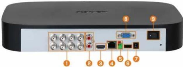
- Video Inputs: Connect Lorex HD or standard analog cameras to the system. For a full list of compatible cameras, visit lorex.com/compatibility.
- Audio IN/Audio OUT: Connect an external microphone for single-channel audio recording, or an external speaker for system audio. For details on connecting external audio devices, see 18 Connecting Audio Devices, page 84.
- HDMI: Connect to an HDMI monitor or TV (not included) to view the system interface.
- LAN: Connect an RJ45 Ethernet cable for local and remote connectivity.
- A/B: Connect RS485 cables.

NOTE
For full details on connecting PTZ cameras, see 17.1 Connecting PTZ Cameras to the Recorder, page 80.
- USB Port: Connect a USB mouse (included) to control the system, or a USB flash drive (not included) for data backup or manual firmware updates.
- DC 12V: Connect the included power adapter.
- VGA: Connect a VGA monitor (not included) to view the system interface.
- ON/OFF Switch: Turns the DVR on/off.
Basic System Setup
4.1 STEP 1: Connect cameras
Test your cameras prior to selecting a permanent mounting location by connecting the cameras and cables to your recorder locally. Push and twist the BNC connector clockwise to secure it to the BNC port.

NOTE
This step is for verification of the camera image only. It is recommended to connect cameras to a nearby power adapter for this step. The Lorex Setup Wizard that runs at startup will assist you in naming and organizing your cameras, so it is also recommended to leave cameras connected until the wizard asks you to install cameras in their permanent mounting location.


NOTE
- Before selecting a permanent mounting location for your cameras, see 5 Camera Installation, page 10 for important notes and installation tips.
- The extension cable must be a single stretch of cable between the recorder and camera. You cannot connect multiple extension cables to each other.
4.2 STEP 2: Connect router
Connect the recorder to your router using the included Ethernet cable.


NOTE
To receive automatic firmware updates and enable remote viewing with mobile apps, a high speed Internet connection is required (minimum upload speed of 3.5Mbps for remote viewing). All other system features can be used without an Internet connection.
4.3 STEP 3: Connect mouse
Connect the included mouse to a USB port on the recorder.
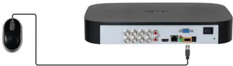
4.4 STEP 4: Connect monitor
Connect the recorder to a monitor using the included HDMI cable.

OR
Connect the recorder to a monitor using a VGA cable (not included).


CAUTION
The system will automatically match the resolution of the connected monitor the first time you use the recorder. If you need to switch monitors, make sure you set the recorder to an output resolution supported by the new monitor BEFORE switching. See 14.5.1 Setting the Recorder's Output Resolution, page 49 for details.
4.5 STEP 5: Connect power
Use the included power adapter to connect the recorder to a nearby outlet. Turn the recorder on using the power switch on the back panel.

4.6 STEP 6: Lorex Setup Wizard
When you first power up your recorder, the Lorex Setup Wizard will begin. The Wizard will help you configure core system settings and set up your cameras. It is recommended to review 5 Camera Installation, page 10 before choosing a permanent mounting position for your cameras.

NOTE
For detailed mounting instructions for your particular camera model, refer to your camera's documentation on lorex.com.
![graph TD A["Local Setup"] --> B["Network Setup"] B --> C["High-speed Internet Connection"] style A fill:#f9f,stroke:#333 style B fill:#ccf,stroke:#333 style C fill:#fff,stroke:#333](/content/2026/05/938670/images/fe6d0ec7cfb7e47c4214f9bc20b7197bdf65b534f0035f372a9069825cc04643.jpg)
You will also create a password that will be used to access the unit from now on. For future reference, it is recommended that you record your password in a secure location.
4.7 STEP 7: Upgrade Firmware to Latest Version (If Available)
If a firmware upgrade is available, you will be asked to install it once the system starts up. It is required to upgrade your system firmware and client software or mobile apps to the latest version to enable remote connection to the system.

NOTE
You must connect your recorder to a router with Internet access in order to get automatic firmware upgrades.
If a firmware upgrade is available:
- After startup, a notification will appear asking you to upgrade the firmware. Click OK to upgrade.
- Enter the system user name (default: admin) and your secure password, then click OK. Wait for the firmware update to complete. The system will restart once the firmware has been upgraded.

CAUTION
DO NOT POWER OFF THE SYSTEM OR DISCONNECT THE POWER CABLE DURING FIRMWARE INSTALLATION.
4.8 Quick Access to System Information
Perform one of the following actions to bring up the system information window. This window contains vital system information including the model number, serial number, and device ID.

NOTE
The QR code shown on this screen can be scanned during mobile setup to enter the system's device ID.

To quickly open a window that displays important system information:
- From the Live View display, right-click to open the Quick Menu, then click Info. OR
- Press the front panel button on the recorder.

NOTE
Do not press and hold the button. The front panel button doubles as a panic button that activates warning lights and sirens for deterrence cameras if held for 3 seconds.
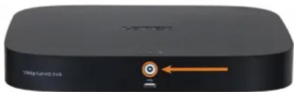
Camera Installation
The following chapter provides general setup instruction and installation tips for security cameras. Ensure that you review 5.2 Ensuring Accurate Person and Vehicle Detection, page 10 for channels you are planning to use Person and Vehicle detection.

NOTE
Cameras differ in terms of mounting instructions. Please see your camera's documentation at lorex.com for specific installation instructions.
5.1 Installation Tips
General camera installation tips that apply to all camera models. Please review before selecting a permanent mounting location for your cameras.
- Test the cameras before permanent installation. Plan where you will route the wiring for the camera and where you will aim the camera.
- Point the camera where there is the least amount of obstructions (e.g., tree branches).
- Mount the camera where the lens is away from direct and intense sunlight.
- Plan your cable wiring so that it does not interfere with power lines or telephone lines.
- Secure cabling so that it is not exposed or easily cut.
- Mount the camera in an area that is visible, but out of reach.
- Avoid pointing the camera at a glass window to see outside. This may result in a bright white ring in the night vision image, as the light from the night vision LEDs may reflect off the glass.
- Adjust the camera angle so that it covers an area with high traffic.
- In "high-risk" locations, have multiple cameras point in the same area. This provides camera redundancy if a vandal attempts to damage one of your cameras.
- For outdoor rated cameras, installation in a sheltered location is recommended to ensure the camera lens remains clear of rainwater and other precipitation.
5.2 Ensuring Accurate Person and Vehicle Detection
The following are important camera installation notes to ensure accurate Person & Vehicle detection. Refer to the documentation that came with your camera or search for your camera model number at lorex.com for full mounting instructions.
- Choose a location where objects of interest will be no further than 50ft (\~15m) from the camera.
• Install the camera between 8-16ft (2.5-5m) off the ground.
• Angle the camera between 30-60° down from the level position. - Optimal accuracy for objects of interest appear in the bottom 1/3 of the camera image.
- Point the camera where there is the least amount of obstructions (i.e. tree branches).


NOTE
Accuracy of Person and Vehicle detection will be influenced by multiple factors, such as the object's distance from the camera, the size of the object, and the height and angle of the camera. Night vision will also impact the accuracy of detection.
5.3 Installing Cameras
- Mount the cameras to the desired mounting surface according to the instructions that came with the cameras (visit lorex.com for the most up-to-date documentation). Choose a firm mounting surface that can support the full weight of the camera.

NOTE
If you wish to mount cameras to drywall, it is recommended to use the included drywall anchors.
- Adjust the camera stand to ensure that the camera has a satisfactory view of the area you would like to monitor. Stand configuration depends on the mounting surface you have chosen (see below for suggested stand configurations).


NOTE
Counter / table top mounting is not recommended if you are planning to utilize Person and Vehicle detection due to limited accuracy.
5.4 Connecting Camera Extension Cables
The extension cable must be a single stretch of cable between the recorder and camera. You cannot connect multiple extension cables to each other. For all extension cable options, including maximum extension cable length, refer to your camera's documentation at lorex.com.
![graph LR A["Input"] --> B["Port 1"] B --> C["Port 2"] C --> D["Port 3"] D --> E["Output"] C --> F["Power Supply"] F --> G["Port 4"]](/content/2026/05/938670/images/77e0627a64feb6f5545f063071e3a9946a65e6314c1ead383dbd3459545c600e.jpg)
- Connect the male power connector on the BNC extension cable to the female power connector on the camera. Connect the BNC connector to the camera.
- Connect the female power connector on the BNC extension cable to the power adapter.
-
Connect the BNC connector to one of the Video Input ports on the rear panel of the recorder.
-
Plug the camera power adapter to a power outlet.
6 Using the Mouse
The mouse is the primary control device for the system. Connect the included mouse to the USB port on the front or rear panel.

1. Left-button:
- In live view, while in a split-screen display mode, click an individual channel to view it in full-screen. Click again to return to the split-screen display mode. - While navigating menus, click to open a menu option.
2. Right-button:
- During live view, right-click anywhere on the screen to open the Quick Menu. - Within system menus, right-click to exit menus.
- Scroll wheel: In live view, use the scroll wheel to zoom in/out.
Using the On-Screen Display
Use the system's on-screen display to navigate menus and configure options and settings.
| NOTE |
| To access the on-screen display, you must connect the included mouse and a monitor (not included) to the recorder. See 4 Basic System Setup, page 6 for full instructions. |
7.1 Navigation Bar
The Navigation Bar along the bottom of the recorder's Live View display allows you to access the Main Menu and control basic functions of the recorder.
To show the Navigation Bar:
• Hover the mouse pointer near the bottom of the Live View screen.
| NOTE |
| You can also lock the Navigation Bar to have it displayed at all times. See below for details. |

- Main Menu: Select for quick access to main operational settings, such as playback, backup, network, and shutdown. See 14 Using the Main Menu, page 45 for full instructions on using the Main Menu.
- Viewing Modes: Select how many channels are shown on screen during live viewing.
- Previous / Next Channel(s): Display previous / next channel(s) in single or quad channel viewing mode.
- Sequence Mode: Start or stop Sequence Mode. In Sequence Mode, the system display will automatically cycle through connected channels every few seconds.
- Playback: Opens the Playback Menu. This allows you to search for video recordings saved on the recorder's hard drive. For details on using the Playback menu, see 9 Playback, page 22.
- Information: Displays system information, such as model number, device ID, IP address, etc.
- Network: View and configure network options, including setting a dynamic or static IP address. For full instructions on configuring network options, see 14.7.1 Selecting DHCP or Static IPAddress (TCP/IP), page 57.
- Hard Drive Manager: Configure hard drive read/write options (see 14.9.6 Configuring Hard Drive Type, page 68 for details) or format drives (see 14.9.5 Formatting the Hard Drive, page 67 for details).
- Updates: Check for available firmware updates — requires an Internet connection.
- Warning Light & Siren — Deterrence Cameras Only: Click to activate warning lights and sirens for all connected deterrence cameras. Click again to deactivate.
- System Date & Time
- Lock Navigation Bar: Choose to always show the Navigation Bar on screen (☐) or hide it until the mouse pointer is near the bottom of the screen (☐).
7.2 Quick Menu
The Quick Menu gives you quick access to functions which can also be accessed using the Navigation Bar.
To open the Quick Menu:
• Right-click anywhere on the Live View screen.
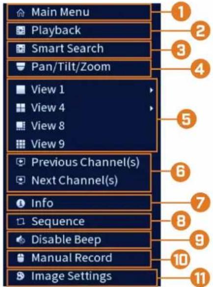
- Main Menu: See 14 Using the Main Menu, page 45 for full instructions on using the Main Menu.
- Playback: Opens the Playback Menu. This allows you to search for video recordings saved on the recorder's hard drive. For details on using the Playback menu, see 9 Playback, page 22.
- Smart Search: Filter through recorded video when searching.
- Pan/Tilt/Zoom: Control and configure settings for Pan-Tilt-Zoom (PTZ) cameras. For full instructions on connecting and using PTZ cameras, see 17.1 Connecting PTZ Cameras to the Recorder, page 80.
- Viewing Modes: Select how many channels are shown on screen during live viewing.
- Previous / Next Channel(s): Change the display to the previous / next channel(s).
- Info: Displays system information, such as model number, device ID, IP address, etc.
- Sequence: Start or stop Sequence Mode. In Sequence Mode, the system display will automatically cycle through connected channels every few seconds.
- Disable Beep: Temporarily disable the current audible warning.

NOTE
Audible warnings can be given for a wide range of events, such as hard drive issues, network connectivity, motion detection events and more. Disabling the current audible alarm using the Quick Menu will silence the recorder only for a short time, then audible warnings will continue.
-
Manual Record: Select manual recording and snapshot options. See 8.4 Setting up Scheduled or Manual Recording, page 19 for details.
-
Image Settings: Configure camera image settings per channel, such as brightness, contrast, etc. For full details on configuring camera image settings, see 14.6.1 Adjusting Camera Image Settings, page 52.
7.3 Camera Toolbar
The Camera Toolbar lets you perform quick functions for a specific channel on the recorder.
To use the Camera Toolbar:
• Hover the mouse near the top of a channel with a connected camera.

- Instant Playback: Plays back recent video from the selected channel. By default, instant playback is set to play the last 5 minutes of recorded video. See 14.8.1 Configuring General System Settings, page 60 to set a custom playback length.
- Digital Zoom: Click to enable digital zoom. Click-and-drag over the camera image to zoom in on the selected area. Right-click to return to the full camera image. You can then repeat to zoom in on a different area, or click the icon again to disable zoom.
- Real-time Backup: Click to start recording the current channel manually. Click again to stop recording and save the video file to a USB flash drive (not included).
- Snapshot: Save a snapshot of the current camera image to a USB flash drive (not included).
- Mute/Unmute: Click to mute/unmute listen-in audio.
- Warning Light — Deterrence Cameras Only: Click to manually turn on the camera's warning light for 10 seconds.
- Siren — Deterrence Cameras Only: Click to manually turn on the camera's siren for 10 seconds.
7.4 On-Screen Keypads
The Full Keypad is used to input alphanumeric characters, such as in user name or password fields. The Number Keypad is used to input numeric characters only, such as in the time or date fields.
To use the Full Keypad:
- Using the mouse, click on a field where alphanumeric characters are entered, such as the user name and password fields.
• The Full Keypad opens:

- Click Shift to switch between uppercase and lowercase characters.
• Right-click to close the Full Keypad.
To use the Number Keypad:
- Using the mouse, click on a field where numeric characters are entered, such as the date or time fields.
• The Number Keypad opens:

• Right-click to close the Number Keypad.
Recording
By default, the system is set to immediately record video from connected cameras continuously, 24 hours a day. You can customize the recording settings according to your needs.
8.1 Video Recording Types
The system supports the following recording types:
- Continuous recording: Normal, continuous recording. A C icon is shown in the bottom left-hand corner of the camera image when continuous recording is in progress.
- Motion recording: Motion-triggered video recording. An M icon is shown in the bottom left-hand corner of the camera image when motion is detected.
8.2 Configuring Recording Quality
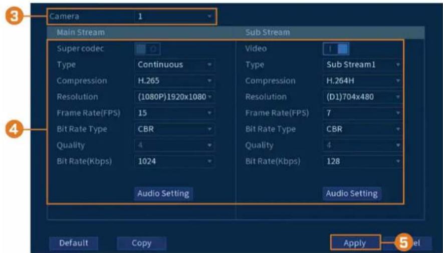
The system uses two video recording streams: a Main Stream and a Sub Stream. The Main Stream records high quality video to your system's hard drive. The Sub Stream records lower resolution video for efficient streaming to devices over the Internet. You can customize the video quality settings for these streams according to your needs.
To configure recording quality:
-
From the Live View display, right-click to open the Quick Menu, then click Main Menu.
-
Click CAMERA . Click the Recording tab on the side panel, then Recording on the top panel.
-
Select the camera you want to configure.
-
Configure the following settings. Except where noted, options for Main Stream and Sub Stream are the same:
- Super Codec: (Main Stream only) Click to enable (I) / disable (O) Super Codec. This setting will help reduce system requirements for unimportant recordings to maximize hard drive storage.
- Video: (Sub Stream only) Click to enable (I) / disable (O) Substream video.

CAUTION
Disabling Substream video will prevent you from viewing the system remotely over the Internet. You should disable the Substream only if you plan on viewing and configuring the system locally.
- Type: For the Main Stream, you can set different recording quality settings for Continuous, MD (Motion Detect), and Alarm recording. Select the type of recording you want to configure.
- Resolution: Select the resolution the selected camera will be recorded at. Higher resolutions create a more detailed image, but take up more hard drive space to record and require more bandwidth to stream to connected computers or mobile devices.
- Frame Rate (FPS): Select the frame rate in Frames Per Second (FPS) that each stream will record at. A higher frame rate provides a smoother picture, but will require more storage and bandwidth.
- Bit Rate Type: Select CBR (Constant Bit Rate) or VBR (Variable Bit Rate) to determine the bit rate type. If you select VBR, select the Quality from 1 (lowest) to 6 (highest).
- Bit Rate (Kbps): Select the bit rate for each recording stream. Higher bit rates provide better image quality, but will require more storage and bandwidth.
5. Click Apply.
- (OPTIONAL) Click Copy to apply the settings for the current channel to one or more other channels (see 14.12 Copying Settings to Another Channel, page 77 for full instructions on using the copy function).
8.3 Setting the Recording Schedule
You can set a custom recording schedule according to your needs. For example, you can set the system to record continuously during business hours and record on motion detection only outside of business hours.
A custom recording schedule helps reduce the amount of hard drive space required, increasing the time your system can retain recordings.
To configure the recording schedule:
-
From the Live View display, right-click to open the Quick Menu, then click Main Menu.
-
Click STORAGE. Click the Schedule tab on the side panel, then Record on the top panel.

-
Under Camera, select the channel you would like to configure or select All.
-
Configure the schedule as needed:
- Check Continuous, Motion (Motion Detection), or Alarm to select the recording type you would like to configure. - Click-and-drag on each day to customize the recording schedule. The schedule is set up as a grid, which each block representing one hour.
- Click beside 2 or more days to link schedules ( ) . This allows you to quickly change multiple schedules at once.
- To make fine adjustments to a schedule, click 📄. This will allow you to set exact start and end times for a schedule.
• To disable all recording of the selected type on the selected day, click
-
Click Apply.
-
(OPTIONAL) Click Copy to apply the settings for the current channel to one or more other channels (see 14.12 Copying Settings to Another Channel, page 77 for full instructions on using the copy function).
8.4 Setting up Scheduled or Manual Recording
You can set the system to record based on a schedule or you can manually turn recording on and off. By default, the system is set to always record on a schedule.
To configure the recording schedule, see 8.3 Setting the Recording Schedule, page 18.
To set options for manual recording:
- From the Live View display, right-click to open the Quick Menu, then click Manual Record.

-
Under Main Stream, select how the system will record the Main Stream for each channel:
-
Auto: Main Stream recording will follow the recording schedule.
- Manual: The system will record the Main Stream continuously as long as this option is checked.
-
Off: The system will not record the Main Stream for this channel. This option is not recommended.
-
Under Sub Stream, select how the system will record the Sub Stream for each channel.
• Auto: Sub Stream recording will follow the recording schedule.
- Manual: The system will record the Sub Stream continuously as long as this option is checked.
- Off: The system will not record the Sub Stream for this channel. This option is not recommended.
-
Under Snapshot, select On to enable snapshot recording on each channel. Or, select Off to disable snapshot recording.
-
Click Apply.
8.5 Configuring Hard Drive Overwrite
When the hard drive is full, the system will overwrite the oldest recordings by default. This is recommended, as it makes sure that your system will continue to record without any input from you. You can also set the system to stop recording once the hard drive is full.
To configure hard drive overwrite:
- From the Live View display, right-click to open the Quick Menu, then click Main Menu.
- Click STORAGE, then click the Basic tab.

- Ensure HDD Full is set to Overwrite to overwrite the oldest recordings when the hard drive is full.
| NOTE |
| Select Stop Record for the system to stop recording when the hard drive is full. |
- Click Apply.
Playback
Search through and playback recorded video files on the system.
9.1 Playing Back Video from the Hard Drive
To play back recorded video:
- From the Live View display, right-click to open the Quick Menu, then click Playback.

-
Use the calendar on the right to select the day to playback.
-
Check the channels you want to play back. Click the icons to the right of each channel name to choose the video quality (M for Main Stream, S for Sub Stream).
-
Click inside the video bar to select the playback time. The system will begin playing back video from the selected time.
9.2 Playback Controls

-
Select Playback Device: Choose between searching the recorder's hard drive or a USB flash drive (not included).
-
Calendar: Select the date to playback.
-
Channel Selection: Select channels and video quality for playback.
4. Viewing Modes:
- Bookmark List: Shows all bookmarked recordings for a single channel on the selected date.
- File List: Shows all available recordings for the selected date and channel(s) in list format.
-
Fullscreen: Shows video in fullscreen. Right-click to return to split-screen viewing.
-
Zoom Playback Bar: Select the scope of the playback bar.
- Recording Type Filters: Click to show/hide recording types.
- Playback Bar: Click inside the bar to select a playback time.
8. Playback Controls:
• / Play / Pause
- Stop
• Play Backwards
• Previous Frame: Go to the previous frame when video is paused.
• Next Frame: Go to the next frame when video is paused.
- Slow Playback: Click repeatedly to slow the video down by half speed up to 16× slower than normal. Click again to return to regular speed.
- Fast Playback: Click repeatedly to double the speed of the video up to 16 × faster than normal. Click again to return to regular speed.
• Volume / Mute: Hover over to reveal the volume bar, where you can set the volume for audio in playback. Click to mute/unmute.

NOTE
Audio recording must be enabled to capture audio in playback recordings. For full instructions on enabling audio recording, see 18 Connecting Audio Devices, page 84.
To hear recorded audio, you must be viewing an audio-enabled camera in single channel. You must also be using an HDMI monitor with built-in speakers, or connect an external speaker to the recorder in order to hear audio.
Digital Zoom: Click to enable digital zoom. Click-and-drag over the camera image to zoom in on the selected area. Right-click to return to the full camera image. You can then repeat to zoom in on a different area, or click the icon again to disable zoom.
Smart Search: Click to select an area of the camera image and play back all recordings with motion in the selected area. For full details on Smart Search, see 9.4 Smart Search, page 25.
Person and Vehicle Filter: Hover over to reveal Person checkbox or Vehicle checkbox. Click to filter recordings on selected channels to show only Person and/or Vehicle detection events.
Snapshot: Save a snapshot of the current camera image to a USB flash drive (not included).
Add Bookmark: Shows.
Video Clip: Back up a custom video clip to a USB flash drive (not included). For full instructions, see 9.5 Video Clip Backup, page 26.
9.3 Playing Back Video from a USB Drive
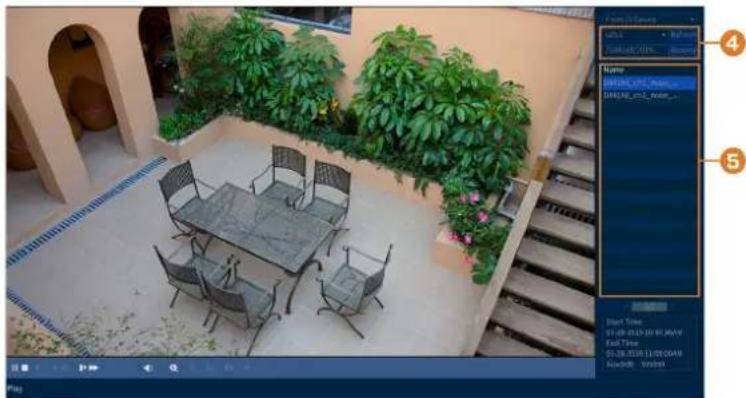
If you have video files saved to a USB flash drive (not included), you can play them back using the system.
For full instructions on backing up video to a USB flash drive, see 10 Backup, page 28.
To play back video from a USB flash drive:
-
Connect the USB thumb drive (not included) with video files on it into a free USB port on the recorder.
-
From the Live View display, right-click to open the Quick Menu, then click Playback.

- Click the dropdown and select From IO Device.
-
Click Browse to locate the video file on your USB flash drive.
-
Double-click the video file you want to open from the file list to start playback.
9.4 Smart Search
Play back all recordings from a single channel with motion in a specific area of the camera image.
To perform a Smart Search:
- From the Live View display, right-click to open the Quick Menu, then click Playback.

- Use the calendar on the right to select the day to playback.
- Check a single channel you want to play back. Click the icon to the right of the channel name to choose the video quality (M for Main Stream, S for Sub Stream).
- Click inside the video bar to select the playback time. The system will begin playing back video from the selected time.
- Click to configure an area for Smart Search.
- The camera image appears with a grid overlay. Click or click-and-drag to add / remove squares from the grid. Solid blue areas mark the area of the image that will be searched for motion events.
- Click to begin Smart Search.
9.5 Video Clip Backup
Video clip backup allows you to select a duration of video during playback mode and save it to a USB device (not included).
To use video clip backup:
- Connect the USB thumb drive (not included) to a free USB port on the recorder.
- From the Live View display, right-click to open the Quick Menu, then click Playback.

-
Use the calendar on the right to select the day to playback.
-
Check the channels you want to play back. Click the icons to the right of each channel name to choose the video quality (M for Main Stream, S for Sub Stream).
-
Click inside the video bar to select the playback time. The system will begin playing back video from the selected time.

-
Click ☒ to mark the beginning of the video clip, then click again to mark the end of the video clip.
-
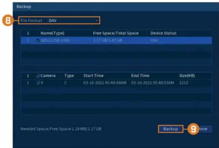
Click ☐ to open the backup menu.
-
Select a filetype for your backup file.
-
Click Backup.
Backup video files to external USB flash drive (not included).
10.1 Formatting the USB Flash Drive
It is recommended to format your USB thumb drive (not included) before using it with the system.

Formatting the USB device will permanently erase all data. This step cannot be undone.
Prerequisite:
- Connect a USB flash drive (not included) to a free USB port on the unit.
To format a USB flash drive:
- From the Live View display, right-click to open the Quick Menu, then click Main Menu.
- Click BACKUP.

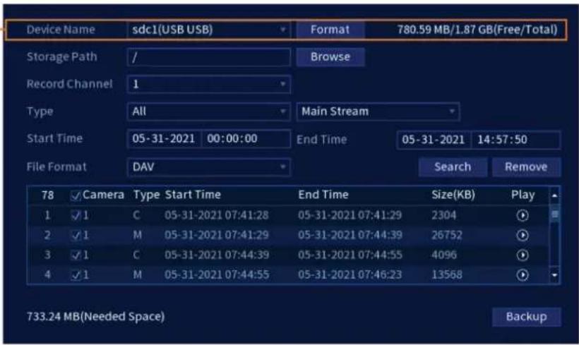
- Click Format next to the Device Name.
-
Select a format mode:
-
FAT32: Recommended — offers the greatest compatibility with other devices.
-
NTFS: Advanced users only — should only be used on drives larger than 32GB where file sizes will be larger than 4GB.
-
Click OK.
10.2 Backing Up Video
You can save video recordings from your system to a USB flash drive. Ensure you format new drives before backing up video (see 10.1 Formatting the USB Flash Drive, page 28 for details).
To backup video:
- From the Live View display, right-click to open the Quick Menu, then click Main Menu.
2. Click BACKUP.

3. Configure the following:
• Device Name: Select the USB device you would like to back up files to.
- Storage Path: Click Browse to locate a folder path on the USB drive to save your files to.
- Record Channel: Select the channel you would like to search or select All to search all channels.
- Type: Select the recording type you would like to search for or select All to search all recording types.
- Start Time / End Time: Select the start and end time for your search.
- File Format: Select DAV to save files to save files to .dav format. You can playback .dav files using the Lorex video player software.
- Click Search . A list of files that match your search criteria appears.
- Check files you would like to backup.
- Click Backup

NOTE
HD video files saved on the system may take up a large amount of disk space. The size of video files selected and the amount of free space on your USB device is shown on screen.
10.3 Using Video Clip Backup
Video clip backup allows you to select a duration of video during playback mode and save it to a USB device (not included). For full instructions on video clip backup, see 9.5 Video Clip Backup, page 26.
10.4 Viewing Backed Up Files
Use the free Lorex Player to play back .dav files.
10.4.1 Viewing Backed Up Files on PC
-
Download and install the Lorex Player for PC from the recorder's product page at lorex.com
-
Double-click one of the files on the left to begin playback.

OR
Click to open a back up video file in another location
- Use the Lorex Player controls to control playback or select other files for playback.
| NOTE |
| For a full overview of Lorex Player controls, see 10.4.3 Lorex Player Controls, page 31. |
10.4.2 Viewing Backed Up Files on Mac
-
Download and install the Lorex Player for Mac from the recorder's product page at lorex.com
-
Double-click the downloaded file in Safari to extract the Lorex Player app file.
-
Drag the Lorex Player app to your Desktop or Applications list. Double-click Lorex Player to open the application.
-
Double-click one of the files on the left to begin playback.

OR
Click to open a back up video file in another location
- Use the Lorex Player controls to control playback or select other files for playback.
| NOTE |
| For a full overview of Lorex Player controls, see 10.4.3 Lorex Player Controls, page 31. |
10.4.3 Lorex Player Controls

- File List: Double-click to open a file.
- Viewing Mode: Select between single-channel viewing and various split-screen options.
- Hide/Show File List
4. Playback Controls:
• : Playback files in sequence.
• : Synchronize playback times.
• : Play/pause playback.
• : Stop playback.
• : Previous frame.
• : Next frame.
• 1X : Playback speed.
• : Volume control.
5. Zoom Timeline
- Display Area: Double-click a video file to expand. Click the controls inside the display area to do the following:
• View information about the video file.
• Start/stop a manual recording from the video file.
• Take a snapshot from the video file.
- ✗: Close the video file.
- Add Files: Click to open backed up video files.
-
Export Files: Export a video file to a different format.
-
Digital Zoom: Click, then click-and-drag over a camera image to zoom in. Right-click to return to the full image.
-
Drag: Click, then click-and-drag to move around a camera image that has been digitally zoomed in.
-
Fullscreen: Click to open the player in full screen. Press ESC to exit full screen.
-
Settings: Click to open the configuration menu for the player. From here you can control the default file formats and save locations for snapshots and control the aspect ratio.

11 Motion Detection
In addition to general motion detection, the system supports smart Person and Vehicle detection. Both types of detection can be configured using the menu shown below.
11.1 Configuring Motion Detection
Set preferences for motion detection on each channel, and select channels you want to enable smart Person and Vehicle detection on.
To configure motion detection:
- From the Live View display, right-click to open the Quick Menu, then click Main Menu.
- Click EVENTS. Click the Event Settings tab on the side panel, then Motion Detect on the top panel.

-
Select a camera to configure motion detection for.
-
Click to enable (1) / disable (0) motion detection on the selected channel.
-
Click Setup next to Area to configure which areas of the image will be enabled for motion detection. A grid will appear on the monitor:

- The camera image appears with a red grid overlay. This means the entire image is enabled for motion detection.
- Click or click-and-drag to add / remove boxes from the active area. Cells that have been removed from the active area appear green.
-
Hover near the top of the image to reveal zone selection. You can set up to 3 different zones with different sensitivity and threshold values.
• Right-click when finished. -
Click Setup next to Schedule to choose which days and times of the week to enable motion detection:

- Click or click-and-drag along the each of the yellow timelines to quickly add or remove time from each day's schedule in 15-minute segments.
- Click beside 2 or more days to link schedules (☐). This allows you to quickly change multiple schedules at once.
-
To make fine adjustments to a schedule, click 📄 This will allow you to set exact start and end times for a schedule.
-
Choose how the system will react when motion is detected:
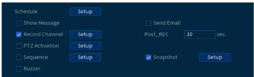
- Show Message: Check to enable an on-screen pop-up when one of your cameras detects motion. On-screen pop-up shows the channels an event occurred on and the type of event.
- Send Email: Check to enable email alerts. You must configure email alerts before you will be able to receive them (see 14.7.3 Configuring Email Alerts, page 58).
- Record Channel: Select the channels that will record when motion is detected on the selected channel. Set the length of recording following a video loss event in the Post_REC field.
- PTZ Activation: Set connected PTZ cameras to start a tour, pattern, or go to a preset location.
- Sequence: Sequence mode will begin. Select the numbered tiles next to this option to include the corresponding channels in the sequence.
- Snapshot: Select the numbered tiles next to this option to save a snapshot of the corresponding channels.
-
Buzzer: Check to enable the system buzzer.
-
Click Smart Motion Detection to enable Person and Vehicle detection:
| NOTE |
| See 5 Camera Installation, page 10 for important camera installation notes related to channels with Person and Vehicle detection enabled. |
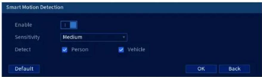
- Click Enable to activate Person and Vehicle detection on the selected channel.
- Select a Sensitivity level (a high sensitivity value will detect smaller objects than a low value).
- Check Person or check Vehicle.
- Click OK when finished.
9. Click Apply.
- (OPTIONAL) Click Copy to apply the settings for the current channel to one or more other channels (see 14.12 Copying Settings to Another Channel, page 77 for full instructions on using the copy function).
11.2 Search for Person and Vehicle Detection Events
Search for Person and Vehicle detection on a specific channel or the entire system. You can also choose to back up events (USB flash drive required - not included).
To search for Person and Vehicle detection events:
- From the Live View display, right-click to open the Quick Menu, then click Main Menu.
- Click EVENTS . Click the Smart Search tab on the side panel, then click on Smart Motion located underneath.
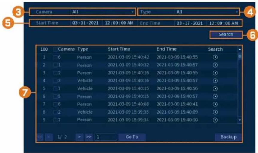
- Select the channel to search for events from, or select All.
- Choose the type of smart motion you want to search for.
- Choose a start and end time for your search.
-
Click Search . Events that match your search criteria appear below.
-
Click 📋 in the Playback column to view the event. If you want to back up events, check the events you want to back up, then click Backup.
12 Active Deterrence
Lorex Active Deterrence cameras feature bright, customizable warning lights and remote-triggered sirens. The recorder allows you to customize automatic light-triggering when motion is detected to deter intruders (see 12.1 Automatic Deterrence Settings, page 37). You can also trigger the lights and sirens manually using the recorder or the Lorex Home app (see 12.2 Manually Activate Deterrence Features, page 39).
For a complete list of compatible deterrence cameras, navigate to your recorder series at lorex.com/compatibility.

12.1 Automatic Deterrence Settings
Set preferences for automatic warning light triggering on compatible Lorex deterrence cameras.
To configure deterrence settings:
-
From the Live View display, right-click to open the Quick Menu, then click Main Menu.
-
Click EVENTS . Click the Event Settings tab on the side panel, then Deterrence on the top panel.

-
Select the channel of a connected deterrence camera.
-
Check Enable
-
Click Setup next to Warning Light to configure preferences:
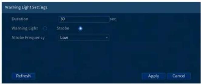
- Duration: Choose how long the warning light will stay on when motion is detected. - Select Warning Light for a solid white light, or Strobe for a flashing light. If you select Strobe, set how quickly the light will flash under Strobe Frequency.
- Click Setup next to Area to set an active area for automatic deterrence.

- The camera image appears with a grid overlay. The green area is the active area for deterrence.
- Click or click-and-drag to add / remove boxes from the active area.
- In the example image above, only motion around the garage or on the porch will trigger the warning light.
-
Right-click when finished.
-
Click Setup next to Schedule to set the weekly schedule for automatic deterrence.

• The default schedule is active during the night, between 5pm and 7am.
- Click on the icon to change the schedule for the corresponding day of the week.
- Click OK when finished.
12.2 Manually Activate Deterrence Features
The system has multiple options for activating deterrence features.
To activate deterrence features on a single camera:
- Hover the mouse pointer near the top of the camera image in Live View to reveal the Camera Toolbar. Click 📄 to activate the warning light, or 🏠 to activate the siren.

- Activate deterrence features using the Lorex Home app. For details, see 15 Connecting Remotely using the Lorex Home Mobile App, page 78.
To activated deterrence features on all connected cameras:
- Push and hold the front panel panic button on the recorder for 3 seconds.

- From the Live View display, click 📋 on the Navigation Bar.

Managing Passwords and User Accounts
Passwords are enabled by default and are required to access the Main Menu or connect to the system using a computer or mobile device. You will be prompted to create a custom password after you connect for the first time.
| NOTE |
| If you forget the password to the system, contact technical support to have it reset. |
13.1 User Accounts
The system includes the following default accounts:
- admin: The administrator account has full access to the system, may configure all system settings, and can manage user accounts.
- user: User accounts are secondary accounts which can be assigned limited access to system settings and camera feeds.
13.1.1 Changing Passwords
You can change the system password of the administrator and user accounts.
To change an account password:
- From the Live View display, right-click to open the Quick Menu, then click Main Menu.
- Click ACCOUNT, then click the User tab.
- Click next to the account you want to change the password for.

4. Configure the following:
- Modify Password: Click to enable (1) password modification.
- Old Password: Enter the current password.
- New Password: Enter the new password you want to use for the system.

NOTE
Passwords for the system must be a minimum of 8 characters, and must include at least 2 of the following character types: lowercase, uppercase, numeric, and special characters.
- Confirm Password: Re-enter the new password.
5. Click OK.
13.1.2 Adding Users
You can allow multiple users to log in to the system. When adding different users, you can assign what menus they have access to. For example, you may want your friend to monitor your system while you are away, while not giving full access to your system.
To add a user:
- From the Live View display, right-click to open the Quick Menu, then click Main Menu.
- Click ACCOUNT, then click the User tab.

3. Click Add User.

4. Configure the following:
- Username: Enter a name for the user account.
- Password: Enter a password for the user account. Enter the password again under Confirm Password.
- Remarks: (Optional) Enter a description of the user account.
- Group: Select the group you would like to assign to this user account. A user account cannot be given permissions its group does not have.
- Period: Setup a schedule for when the added user can access the system.
- Authority: Check the permissions you would like the user account to have. Under the System tab, select the menus the user account may access. Under the Playback tab, select which channels the user account may access recorded video from. Under the Covert tab, select the channels the user account may view live video from.
- User MAC: Not supported — leave blank.
5. Click OK.

NOTE
Now, you can log in to the system locally, or remotely using the user name and password you created. When logging into the system with a user account, the user will only have access to the menus you assigned.
13.1.3 Modifying Users
Modify account details, such as account username or permissions.
To modify a user:
- From the Live View display, right-click to open the Quick Menu, then click Main Menu.
- Click ACCOUNT, then click the User tab.

next to the account you want to modify.
-
Click next to the account you want to modify.
-
Update account details as needed, then click OK.
13.1.4 Deleting Users
Remove a user from the system.
To remove a user:
- From the Live View display, right-click to open the Quick Menu, then click Main Menu.
- Click ACCOUNT, then click the User tab.

next to the account you want to delete.
-
Click 📄 next to the account you want to delete.
-
Click OK.
13.2 Account Groups
Account groups can be used to easily manage permissions for multiple user accounts. User accounts can be given all the permissions of a group, but cannot be given permissions that the group does not have.
The system includes the following groups by default:
- admin: Accounts in the admin group are system administrators. They have full access to the system, may configure all system settings, and can manage user accounts.
- user: Accounts in the user group are normal users. They have limited access to system menus.
13.2.1 Adding Groups
Add a new group with unique system permissions.
To add a group:
-
From the Live View display, right-click to open the Quick Menu, then click Main Menu.
-
Click ACCOUNT, then click the Group tab.

- Click Add Group.

-
Configure the following:
-
Group Name: Enter a name for the group.
- Remarks: (Optional) Enter a description of the group.
-
Authority: Check the permissions you would like the user account to have. Under the System tab, select the menus the user account may access. Under the Playback tab, select which channels the user account may access recorded video from. Under the Covert tab, select the channels the user account may view live video from.
-
Click OK.
13.2.2 Modifying Groups
Change an existing group's name or permissions.
To modify a group:
- From the Live View display, right-click to open the Quick Menu, then click Main Menu.
- Click ACCOUNT, then click the Group tab.
- Click next to the group you want to modify.
- Update group details as needed, then click OK.
13.2.3 Deleting Groups
Remove a group.
To delete a group:
- From the Live View display, right-click to open the Quick Menu, then click Main Menu.
-
Click ACCOUNT, then click the Group tab.
-
Click next to the group you want to delete.
-
Click OK.
Using the Main Menu
To access the main menu:
- From the Live View display, right-click to open the Quick Menu, then click Main Menu. OR
- Click on the Navigation Bar, then click Main Menu.

14.1 Main Menu's Navigation Bar
The Main Menu's Navigation Bar can be found along the top of the settings display which allows easy access to different settings within the Main Menu.
To show the Main Menu Navigation Bar:
- Click on any of the main menu's settings.

- Playback: Opens the Playback Menu. This allows you to search for video recordings saved on the recorder's hard drive. For details on using the Playback menu, see 9 Playback, page 22
- Events: Set preferences for events such as video loss, motion detection, Person/Vehicle detection, Face Detection, Face Recognition, and system warnings. The Events menu is also used to set preferences for deterrence cameras.
- Backup: Backup video files to external USB flash drive (not included).
- Display: Set the system's monitor resolution, configure Sequence mode, and other display settings.
- Camera: Configure image settings, recording parameters, channel overlay, and privacy masking.
- Network: View and configure network options, including setting a dynamic or static IP address. For full instructions on configuring network options, see 14.7.1 Selecting DHCP or Static IP Address (TCP/IP), page 57.
- System: Configure general system settings, such as date & time, time zone, and DST.
- Storage: Configure recording schedule and set preferences for hard drives connected to the system.
- Account: Modify account details, such as account username or permissions.
14.2 Playback
See chapter 9 Playback, page 22 for details.
14.3 Events
Set preferences for events such as video loss, motion detection, Person/Vehicle detection, Face Detection, Face Recognition, and system warnings. The Events menu is also used to set preferences for deterrence cameras.
14.3.1 Video Loss
Configure video loss settings and how the system reacts to a video loss event. Video loss means that video from one or more cameras was interrupted or disabled. It could be caused by a number of factors, such as a loose or damaged connection, loss of power to a camera, or a blocked camera lens.
To configure video loss settings:
-
From the Live View display, right-click to open the Quick Menu, then click Main Menu.
-
Click EVENTS. Click the Event Settings tab on the side panel, then Video Loss on the top panel.

-
Select a channel to configure.
-
Click to enable (I) / disable (O) video loss events for the selected channel.
-
Click to set a weekly schedule for video loss events. By default, video loss events are enabled at all times.
- Click or click-and-drag along the each of the yellow timelines to quickly add or remove time from each day's schedule in 15-minute segments.
- Click beside 2 or more days to link schedules (☐). This allows you to quickly change multiple schedules at once.
- To make fine adjustments to a schedule, click the icon 📋 This will allow you to set exact start and end times for a schedule.
-
Choose how the system will react when video loss occurs:
-
Show Message: Video loss error message will appear on the recorder's display.
- Record Channel: Select the numbered tiles next to this option to record video from the corresponding channels. Set the length of recording following a video loss event in the Post REC field.
- PTZ Activation: Set connected PTZ cameras to start a tour, pattern, or go to a preset location.
- Sequence: Sequence mode will begin. Select the numbered tiles next to this option to include the corresponding channels in the sequence.
- Snapshot: Select the numbered tiles next to this option to save a snapshot of the corresponding channels.
- Buzzer: The recorder will sound an audible alarm.
- Send Email: Send an email notification with details on the event (requires email configuration — see 14.7.3 Configuring Email Alerts, page 58 for details).
7. Click Apply.
- (OPTIONAL) Click Copy to apply the settings for the current channel to one or more other channels (see 14.12 Copying Settings to Another Channel, page 77 for full instructions on using the copy function).
14.3.2 System Warnings
The system is set to provide warnings for various events and issues. The warning menu is broken into 2 event types: hard drive events and network events.
To set preferences for hard drive events:
- From the Live View display, right-click to open the Quick Menu, then click Main Menu.
- Click EVENTS. Click the Warning tab on the side panel, then HardDisk on the top panel.

-
Choose the event type you want to set preferences for:
-
No Disk: No hard drive detected.
- Disk Error: A hard drive error has been detected.
-
Disk Full: The hard drive is full or almost full. Enter the percentage of disk space remaining that will trigger a warning next to Less Than. Disk Full warnings will not occur if hard drive overwrite is enabled.
• All: Configure warnings for all hard drive events. -
Click to enable (I) / disable (O) the selected event type.
-
Choose how the system will react when the selected event occurs:
-
Show Message: Error message will appear on the recorder's display.
- Buzzer: The recorder will sound an audible alarm.
- Send Email: Send an email notification with details on the event (requires email configuration — see 14.7.3 Configuring Email Alerts, page 58 for details).
6. Click Apply.
To set preferences for network events:
-
From the Live View display, right-click to open the Quick Menu, then click Main Menu.
-
Click EVENTS. Click the Warning tab on the side panel, then Network on the top panel.
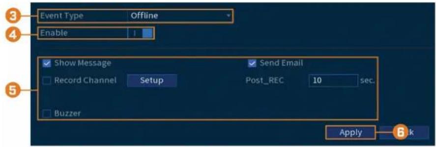
-
Choose the event type you want to set preferences for:
-
Offline: The system has lost connection to the network.
- IP Conflict: More than one device on your network has the same IP address.
- MAC Conflict: More than one device on your network has the same MAC address.
-
All: Configure warnings for all network events.
-
Click to enable (I) / disable (O) the selected event type.
-
Choose how the system will react when the selected event occurs:
-
Show Message: Error message will appear on the recorder's display.
- Record Channel: For Offline events only. Select the numbered tiles next to this option to record video from the corresponding channels. Set the length of recording following a network disconnection event in the Post_REC field.
- Buzzer: The recorder will sound an audible alarm.
-
Send Email: Send an email notification with details on the event (requires email configuration — see 14.7.3 Configuring Email Alerts, page 58 for details).
-
Click Apply.
14.3.3 Searching Event Logs
Search all channels for events, including motion detection and video loss.
To search for events:
- From the Live View display, right-click to open the Quick Menu, then click Main Menu.
- Click Events, then click the Event Log tab.

- Select an event type to search for.
- Enter a start and end time for your search.
-
Click Search.
-
Events that match your search criteria are displayed:
-
The Type column is formatted to show <|Event Type|: |Channel Number|> .
- Click Details to see more information on the selected event.
- Motion events have more options than other events. You can view the event by clicking
in the Playback column, or back up the video clip to a USB flash drive (not included) by clicking Backup.
14.4 Backup
See chapter 10 Backup, page 28 for details.
14.5 Display
Set the system's monitor resolution, configure Sequence mode, and other display settings.
14.5.1 Setting the Recorder's Output Resolution
The first time you power up the system and complete the Lorex Setup Wizard, the system will automatically match the resolution of the connected monitor. You can set the recorder to a different output resolution at any time.

CAUTION
If you need to switch the monitor used with the system, make sure you set the recorder to an output resolution supported by the new monitor before switching.
To change the output resolution:
- From the Live View display, right-click to open the Quick Menu, then click Main Menu.
- Click DISPLAY, then click the Display tab.

- Set the resolution to match the highest resolution supported by your monitor. For example, select 3840 × 2160 for 4K monitors, or 1920 × 1080 for 1080p.
- Click Apply. The recorder will restart before changes take effect.
14.5.2 Listen-In Audio
Enable and set volume for camera audio feeds in the Live View display.

NOTE
Audio will only be heard if you are viewing an audio-enabled camera in single-channel view. You will also need an HDMI monitor with built-in speakers, or an external speaker connected to the recorder's Audio Out port (see 18 Connecting Audio Devices, page 84 for details).
To set preferences for listen-in audio:
- From the Live View display, right-click to open the Quick Menu, then click Main Menu.
- Click DISPLAY, then click the Display tab.
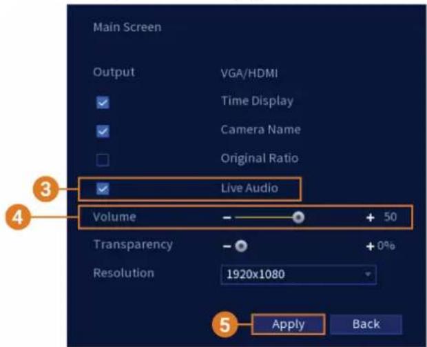
- Check Live Audio.
- Set the desired volume for live audio.
- Click Apply.
14.5.3 Menu T transparency
Set the level of transparency for system menus.
To set menu transparency:
- From the Live View display, right-click to open the Quick Menu, then click Main Menu.
- Click DISPLA Y, then click the Display tab.

- Set the desired transparency value. The transparency of the current menu will update instantly to show how other menus will be affected.
- Click Apply.
14.5.4 General Display Settings
Configure miscellaneous display settings.
To configure general display settings:
- From the Live View display, right-click to open the Quick Menu, then click Main Menu.
- Click DISPLAY, then click the Display tab.

- Check to display system time during Live View.

NOTE
Disabling time display will not affect timestamps in recorded video.
-
Check to display channel names during Live View.
-
Check Original Rate to display camera images in their original proportions.
-
Click Apply.

NOTE
You can also adjust where the time and channel name overlays are positioned on screen. See 14.6.3 Changing On-Screen Overlay, page 54 for details.
14.5.5 Configuring Sequence Mode
Sequence mode cycles through connected channels to give you an overview of what is happening on all cameras. You can customize the order that channels appear in Sequence mode, as well as configure which viewing modes should be used.
To configure Sequence mode:
-
From the Live View display, right-click to open the Quick Menu, then click Main Menu.
-
Click DISPLAY, then click the Sequence tab.

- Click to enable (I) / disable (O) Sequence mode.

- Enter the time in seconds to remain on each channel or split screen during Sequence mode.
- Choose how many channels will appear on screen when Sequence mode is triggered by motion detection (must be configured separately — see 11 Motion Detection, page 33 for details).
- Select a viewing mode to configure. It is recommended to start with View 1 and make your way to View 9. By default, all viewing modes are included in the Sequence mode cycle.
- Configure the order of channels shown on screen for each viewing mode. Uncheck channels / channel groups that you want to remove from the Sequence mode cycle.
- Click Apply.
14.6 Camera
Configure image settings, recording parameters, channel overlay, and privacy masking.
14.6.1 Adjusting Camera Image Settings
Adjust the color and image quality settings of your cameras.
-
From the Live View display, right-click to open the Quick Menu, then click Main Menu.
-
Click CAMERA, then click the Image Settings tab.

- Select the channel you want to configure.
- Select COAXIAL for cameras connected using BNC cabling, or UTP for balun installations.
- Configure the color settings for the selected channel.
- Click Apply.
14.6.2 Configuring Snapshot Recording
The system can be set to record snapshot images when a camera detects motion. These snapshots can be viewed through the Playback menu or attached to email alerts and push notifications. The Snapshot tab in the Recording menu controls the quality and recording parameters for each camera.
To configure snapshot recording:
- From the Live View display, right-click to open the Quick Menu, then click Main Menu.
- Click CAMERA . Click the Recording tab on the side panel, then Snapshot on the top panel.
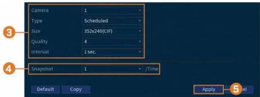
-
Configure the following settings for snapshots saved automatically from motion detection or the snapshot schedule:
-
Camera: Select the camera you would like to configure.
- Type: Select Schedule for the system to take snapshots according to the snapshot schedule (see 14.9.4 Setting the Snapshot Schedule, page 66). Select Event for the system to take snapshots according to the event schedule.
• Size: Select the resolution for snapshots.
• Quality: Select the snapshot image quality between 1 (lowest) and 6 (highest). -
Interval: Enter the interval between snapshots in seconds.
-
Under Snapshot, select the number of snapshots the system will take when the snapshot button is pressed.
- Click Apply.
- (OPTIONAL) Click Copy to apply the settings for the current channel to one or more other channels (see 14.12 Copying Settings to Another Channel, page 77 for full instructions on using the copy function).
14.6.3 Changing On-Screen Overlay
Remove or change the location of the date/timestamps and channel names. You can also change channel names from this menu.
To change the on-screen overlay:
- From the Live View display, right-click to open the Quick Menu, then click Main Menu.
- Click CAMERA. Click the Overlay tab on the side panel, then Overlay on the top panel.

- Select the camera you want to configure.
- Click-and-drag the blue boxes on the camera image to adjust the location of the date/time and channel name.
- Use the checkboxes to enable/disable overlays. If needed, use the text field next to Camera Name to adjust the camera name.
- Click Apply.
- (OPTIONAL) Click Copy to apply the settings for the current channel to one or more other channels (see 14.12 Copying Settings to Another Channel, page 77 for full instructions on using the copy function).
14.6.4 Configuring Privacy Masking
A privacy mask blocks out a portion of the camera image with a black box, letting you have privacy in certain parts of a camera image. You can configure up to 4 privacy zones per channel.
To configure privacy masking:
-
From the Live View display, right-click to open the Quick Menu, then click Main Menu.
-
Click CAMERA. Click the Overlay tab on the side panel, then Privacy Masking on the top panel.

-
Select the camera you want to configure.
-
Configure the following settings:
-
Preview: Check to set and preview privacy masks.
- 1–4: Click the numbered boxes to create a corresponding privacy mask on the camera image.
-
Record: Check to include privacy masks in video recordings. Leave unchecked if you would like privacy masks only to show during Live View.
-
Active privacy masks are shown on the camera image. Click-and-drag to move a privacy mask, or click-and-drag the edge of a privacy mask to resize it.
-
Click Apply.
14.6.5 Connecting Multi-Format Cameras (Cable Type)
The recorder works with multiple types of HD analog cameras. By default, the system is set to automatically detect the type of camera so it works instantly with the recorder. If you experience issues with image clarity or camera performance, you can set certain channels to a specific HD standard.
To manually change the camera format:
-
From the Live View display, right-click to open the Quick Menu, then click Main Menu.
-
Click CAMERA, then click the Cable Type tab.
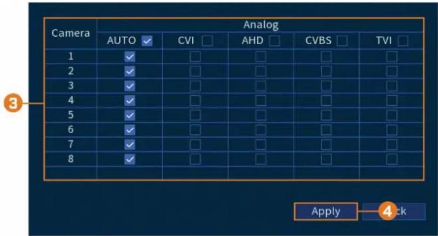
- By default, all channels are set to AUTO to automatically detect the camera's format. Change the selection for each channel as needed.
- Click Apply.
14.6.6 Camera Firmware Upgrade (CVI Upgrade)
Manually upgrade camera firmware. This is typically only necessary if directed to do so by Lorex technical support.
Prerequisite:
- Connect a USB flash drive (not included) to the recorder with the .bin camera firmware file (s) preloaded.
To manually upgrade camera firmware:
- From the Live View display, right-click to open the Quick Menu, then click Main Menu.
- Click CAMERA, then click the CVI Upgrade tab.
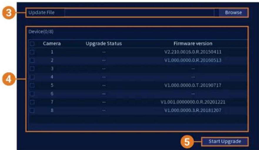
- Click Browse to search for the .bin firmware file on the USB flash drive.
- Check cameras you would like to upgrade using the selected firmware file.
- Click Start Upgrade.
14.7 Network
Configure network parameters for your system.
14.7.1 Selecting DHCP or Static IP Address (TCP/IP)
The TCP/IP menu allows you to configure IP address settings.
To configure basic networking settings:
- From the Live View display, right-click to open the Quick Menu, then click Main Menu.
- Click NETWORK, then click the TCP/IP tab.
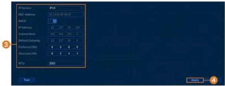
3. Configure the following settings:
• IP Version: Select IPv4 or IPv6.
- DHCP: Click to enable (I) / disable (O) DHCP. It is recommended to enable DHCP to let the system automatically obtain an IP address from the router. If you are an advanced user, disable DHCP to assign a static IP address to the system. To assign a static IP address, configure the following:
- IP Address: Enter the IP address you would like to assign to the system. Make sure that no other device on your network is using the same IP address.
- Subnet Mask: Enter the subnet mask for your network.
Default Gateway: Enter the gateway address for your network.
• Preferred DNS: Enter the address of your primary DNS server.
• Alternate DNS: Enter the address of your secondary DNS server.
- MTU: (Advanced users only) Enter the value for the network card.
4. Click Apply.
14.7.2 Configuring System Ports (Connection)
Configure ports used by the system. If you are using DDNS connectivity, port forwarding is required for the HTTP Port (default: 80) and TCP Port (Client Port) (default: 35000).

NOTE
Port forwarding is not required unless you are using DDNS for remote access. Using mobile apps does not require port forwarding or DDNS setup.
To configure system ports:
-
From the Live View display, right-click to open the Quick Menu, then click Main Menu.
-
Click NETWORK, then click the Port Number tab.

- Configure the port numbers as needed.
- Click Apply.
14.7.3 Configuring Email Alerts
You can configure the system to send out email alerts for motion detection or other events.

NOTE
To send out motion detection alerts, you must enable the Send Email option for motion detection on each camera you would to receive alerts from. For details, see 11 Motion Detection, page 33.
To configure email alerts:
- From the Live View display, right-click to open the Quick Menu, then click Main Menu.
- Click NETWORK, then click the Email tab.


- Click to enable (1) email alerts.
4. Configure the following:
If you want to use Lorex's email server (recommended):
- Mail Select: Select Lorex Mail.
- Receiver: Select up to 3 email addresses that will receive alerts. Enter each email address into the field Email Address below.
- Subject: Enter a subject line for email alerts.
- Attachment: Enable (1) to include a image attachment of the camera.

NOTE
You must enable the Snapshot option for motion detection on each camera you would to receive attachments. For details, see 11 Motion Detection, page 33.
- Sending Interval: Enter the interval in minutes between email alerts.
- Health: Check to enable health check emails. Health check emails will be sent periodically to ensure that the system is functioning normally.
- Sending Interval: Enter the interval in minutes for health check emails.
If you want to use your own email server (advanced):
- Mail Select: Select the mail server you want to use, or select Customize to use your own.
- SMTP Server: Enter the SMTP server address.
• Port: Enter the port used by the SMTP server. - Username: Enter the SMTP user name.
- Password: Enter the SMTP password.
- Email Schedule: Click to setup a weekly schedule for email alerts.
- Receiver: Select up to 3 email addresses that will receive alerts. Enter each email address into the field Email Address below.
- Sender: Enter the sender's email address.
- Subject: Enter a subject line for email alerts.
- Attachment: Enable (1) to include a image attachment of the camera.

NOTE
You must enable the Snapshot option for motion detection on each camera you would to receive attachments. For details, see 11 Motion Detection, page 33.
- Encrypt Type: Select SSL or TLS if your server uses encryption. Select None if your server does not use encryption.
- Sending Interval: Enter the interval in minutes between email alerts.
- Health: Check to enable health check emails. Health check emails will be sent periodically to ensure that the system is functioning normally.
-
Sending Interval: Enter the interval in minutes for health check emails.
-
Click Test to send a test email to ensure settings are configured properly.
- Click Apply.
14.7.4 P2P Setting
The P2P Setting menu is used only to enable / disable remote access to the system using a P2P connection.

CAUTION
P2P connection is the primary method used for remote access to your security system using the Lorex IHome app. If you disable P2P connectivity, you will only be able to access your system over the Internet using DDNS. See 20 DDNSSetup (Advanced), page 93 for details.
To change P2P setting:
-
From the Live View display, right-click to open the Quick Menu, then click Main Menu.
-
Click NETWORK, then click the P2P tab.

- Click Apply.
14.8 System
Configure general system settings, such as date & time, time zone, and DST. It also allows you to check for firmware updates over the Internet and restore the system to default settings.
14.8.1 Configuring General System Settings
Configure miscellaneous system settings.
To configure general system settings:
- From the Live View display, right-click to open the Quick Menu, then click Main Menu.
- Click SYSTEM, click the General tab, then General on the top panel.
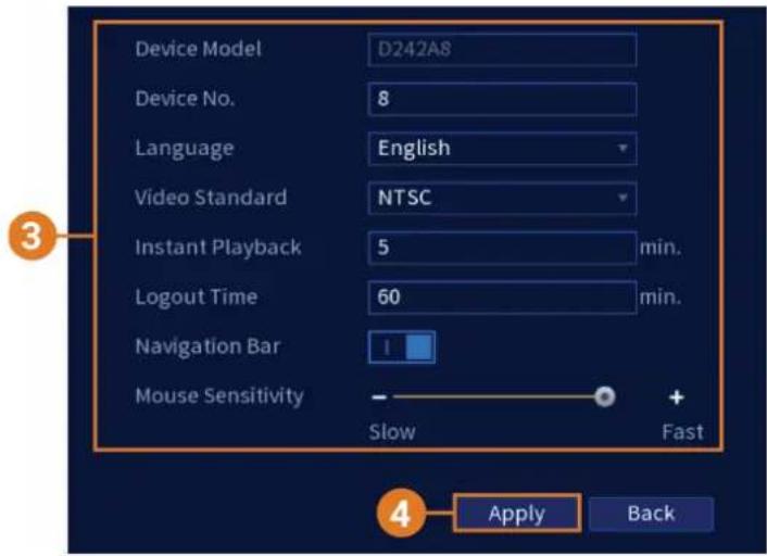
3. Configure the following:
• Device Model: Shows the model number of your system.
• Device No.: Select the remote control address of the system.
• Language: Set the system languages. Available options are English, French, and Spanish.
• Video Standard: Select NTSC (North America) or PAL (Europe).
- Instant Playback: Select the amount of time (in minutes) the system will go back when instant playback is activated in live view.
- Logout Time: Select the idle time (in minutes) before the system will logout the current user.
- Navigation Bar: Check to enable the Navigation Bar that comes up when you left click in live view.
- Mouse Pointer Speed: Use the slider to adjust the mouse speed.
4. Click Apply.
14.8.2 Setting Date & Time
As part of the initial setup, you will set the system date & time. This menu allows you to adjust the date & time, and configure settings for Daylight Savings Time (DST) and Network Protocol Time (NTP).

CAUTION
It is important to always ensure your system date and time are accurate. Inaccurate time stamps may render your footage unusable for court evidence.
To set system date and time:
-
From the Live View display, right-click to open the Quick Menu, then click Main Menu.
-
Click SYSTEM, then click the General tab, then Date&Time on the top panel.

3. Configure system time:
- System Tim e: Set the current date and time.
• Time Zone: Select your system time zone. - Date Format: Choose how the date and time appear.
-
Date Separator: Choose the symbol that separates date from time.
• Time Format: Choose from 12-hour or 24-hour time. -
Configure Daylight Savings Time (DST) settings:
-
DST: Click to enable ( I ) / disable ( O ) Daylight Savings Time.
- Select Week to set the start and end time based on a day and week (e.g., 2nd Sunday of March), or select Date to set the start and end time to a specific date.
-
Start Time / End Time: Set start and end times for DST. Format will change depending on your selection for either Week or Date.
-
Configure Network Time Protocol (NTP) settings:
| NOTE |
| Your system must have a constant connection to the Internet to use NTP. |
- NTP: Click to enable (1) / disable (0) Network Protocol Time.
• Server Address: (Advanced users only) Enter a custom NTP server.
- Port: (Advanced users only) Enter a custom NTP port.
- Interval: Select how often the system will sync time with the NTP server.
- Click Apply.
14.8.3 Configuring Holidays
You can set certain days as holidays. Holidays have a special recording schedule.
| NOTE |
| Ensure you adjust the holiday recording schedule to your preferences. See 8.3 Setting the Recording Schedule, page 18 for details. |
To configure holidays:
- From the Live View display, right-click to open the Quick Menu, then click Main Menu.
- Click SYSTEM, click the General tab, then Holiday on the top panel.
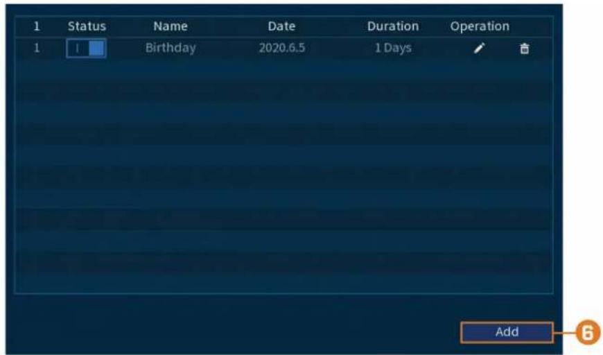
3. Click Add.

4. Configure the following:
• Name: Enter a name for this holiday.
- Effective Mode: Select Once for the holiday to occur only this year or Always for the holiday to be repeated each year.
- Period: Select Date to select a specific date, or select Week to select holidays based on which week they fall on.
- Start Time / End Time: Set the start and end time for this holiday.
- Add More: Enable to add another holiday after you click OK.
5. Click OK.
14.8.4 Configuring IP Filter
Configure permissions for external IP addresses attempting to access the unit.
To configure the IP filter:
- From the Live View display, right-click to open the Quick Menu, then click Main Menu.
- Click SYSTEM, click the Security tab, then click Firewall on the top panel.
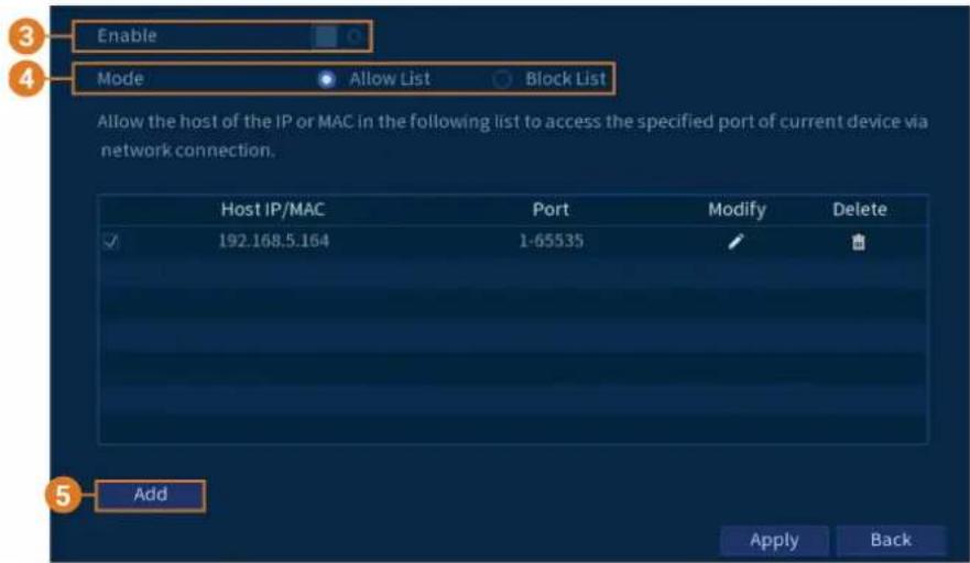
- Click to enable (I) / disable (O) the selected filter type.
- Under Mode, select which type of filter to apply:
- Allow List: IP addresses that are permitted to access the recorder.
- Block List: IP addresses that are not permitted to access the recorder.
- Click Add to enter an IP address.
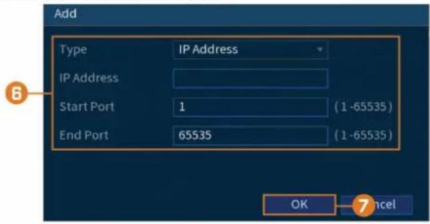
-
Configure the following:
-
Type: Select the address type.
- IP Address: Enter a single IP address for the selected filter type.
-
Start Port: The port you want to open.
• End Port: The port you want to end at. -
Click OK
-
Click Apply.
14.8.5 Configuring IP Filter — Sync Time
Configure permissions for external IP addresses that are permitted to sync the recorder's time.
To configure the IP filter:
- From the Live View display, right-click to open the Quick Menu, then click Main Menu.
- Click SYSTEM, click the Security tab, then click Sync Time-Allowlist on the top panel.
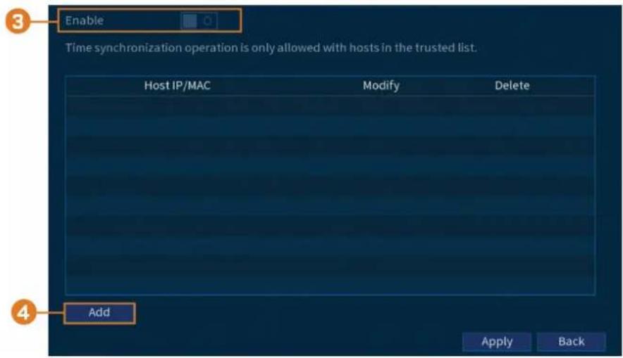
- Click to enable (1) / disable (0) the selected filter type.
- Click Add.
5. Configure the following:

• Type: Select the address type.
- IP Address: Enter a single IP address for the selected filter type.
6. Click OK.
7. Click Apply.
14.9 Storage
Configure recording schedule and set preferences for hard drives connected to the system.
14.9.1 Configuring Hard Drive Overwrite
When the hard drive is full, the system will overwrite the oldest recordings by default. This is recommended, as it makes sure that your system will continue to record without any input from you. You can also set the system to stop recording once the hard drive is full.
To configure hard drive overwrite:
- From the Live View display, right-click to open the Quick Menu, then click Main Menu.
- Click STORAGE, then click the Basic tab.

- Ensure HDD Full is set to Overwrite to overwrite the oldest recordings when the hard drive is full.
| NOTE |
| Selecting Stop for the system to stop recording when the hard drive is full. |
4. Click Apply.
14.9.2 Configuring Recording File Length
Select how the system will store video files.
To configure recording length:
-
From the Live View display, right-click to open the Quick Menu, then click Main Menu.
-
Click STORAGE, then click the Basic tab.

- Next to Package Mode, select Time Length for the system to package recording files based on recording length, or File Size to package based on file size. The field next to the drop-down will change between minutes and megabytes (MB) depending on your selection.
| NOTE |
| Selecting Stop for the system to stop recording when the hard drive is full. |
- Click Apply.
14.9.3 Configuring Pre-Recording
The system can pre-record video when motion detection events occur.
To configure pre-recording:
- From the Live View display, right-click to open the Quick Menu, then click Main Menu.
- Click STORAGE. Click the Schedule tab on the side panel, then Record on the top panel.

- Under Channel, select the channel you would like to configure or select All.
- Set the duration for pre-recording in seconds.
- Click Apply.
- (OPTIONAL) Click Copy to apply the settings for the current channel to one or more other channels (see 14.12 Copying Settings to Another Channel, page 77 for full instructions on using the copy function).
14.9.4 Setting the Snapshot Schedule
You can set a schedule for recording snapshots from the cameras.
To set the snapshot schedule:
-
From the Live View display, right-click to open the Quick Menu, then click Main Menu.
-
Click STORAGE. Click the Schedule tab on the side panel, then Snapshot on the top panel.

-
Under Camera, select the channel you would like to configure or select All.
-
Configure the schedule as needed:
- Check Continuous, Motion (Motion Detection), or Alarm to select the recording type you would like to configure.
- Click-and-drag on each day to customize the recording schedule. The schedule is set up as a grid, which each block representing one hour.
- Click beside 2 or more days to link schedules ( ) . This allows you to quickly change multiple schedules at once.
- To make fine adjustments to a schedule, click 📋. This will allow you to set exact start and end times for a schedule.
• To disable all recording of the selected type on the selected day, click
-
Click Apply.
-
(OPTIONAL) Click Copy to apply the settings for the current channel to one or more other channels (see 14.12 Copying Settings to Another Channel, page 77 for full instructions on using the copy function).
14.9.5 Formatting the Hard Drive
If you install a new hard drive, you must format the hard drive using the system before you will be able to record.

Formatting the hard drive erases all data on the hard drive. This step cannot be undone.
To format hard drives:
-
From the Live View display, right-click to open the Quick Menu, then click Main Menu.
-
Click STORAGE, then click the HDD Manager tab.
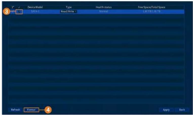
-
Check the hard drive you want to format.
-
Click Format. The system will restart to complete the formatting process.
14.9.6 Configuring Hard Drive Type
The system supports the following hard drive types:
- Read-write HDD: Normal recording hard drive.
- Read-only HDD: The system can playback data from this hard drive, but it will not record to it.
To configure hard drive types:
-
From the Live View display, right-click to open the Quick Menu, then click Main Menu.
-
Click STORAGE, then click the HDD Manager tab.

-
Under Type next to the hard drive you want to configure, select Read/Write or Read only.
-
Click Apply.
14.9.7 Recording Calculator (REC Estimate)
Use the recording calculator to get an estimate of your maximum recording time in days for the installed hard drive, or how much hard drive space would be required to retain a specific amount of days.
To obtain a recording estimate:
-
From the Live View display, right-click to open the Quick Menu, then click Main Menu.
-
Click STORAGE, then click the Rec Estimate tab.

- Select Recording Days for the total number of days worth of recordings your hard drive can store, or select Disk Requirement for the total storage needed to record for a specific number of days.
- For Recording Days mode, click Select to choose your hard drive from a list to output the total number of days your hard drive can store. For Disk Requirement mode, enter a number of days to output the total amount of storage required.
14.9.8 FTP (Advanced)
Send recordings and/or snapshots to an FTP server.
To configure FTP settings:
- From the Live View display, right-click to open the Quick Menu, then click Main Menu.
- Click STORAGE, then click the FTP tab.

- Click to enable (I) / disable (O) FTP connection, and select either FTP or SFTP depending on your configuration.
4. Configure the following:
- Server Address: Enter the FTP server's address.
• Port: Enter the FTP port. - Username: Enter your FTP username.
- Password: Enter your FTP password.
- Anonymous: Enable if your FTP server supports anonymous login.
- Storage Path: Enter the path to save recordings and/or snapshots to...
- File Size: Enter the recording file length in minutes.
- Camera: Select a camera to set FTP recording preferences for.
- Day: Select a day of the week to configure FTP recording settings for, or select All to apply to all days of the week.
- Period 1 \~ Period 2: Select up to 2 periods of time where the system will save recordings to the FTP. Check Alarm, MD (Motion Detection), or Continuous beside each period to determine which recording type will be uploaded to the FTP.
• Image Upload Interval: Enter the interval between snapshots in seconds. - Camera: Setup a camera to set the snapshots for.
5. Click Apply.
14.10 Account
See chapter 13 Managing Passwords and User Accounts, page 40 for details.
14.11 Information
Menus that show you different types of system information.
14.11.1 Version
The Version sub-menu allows you to view information about the current firmware installed on the system.
| Device ID | LHVZ7276F0998F2 |
| Device Model | D242A8 |
| Firmware Version | 00004 |
| IE Version | 3.2.7.83177 |
| Build Date | 05-21-2021 |
| SN | ND012102077739 |
| IP Address | 192.168.5.165 |
| MAC Address | 00:1f:54:5e:ad:f9 |
| Domain Name | DDNS setup is not available |
| HDD Capacity | 0G/1862G |
| Video Format | NTSC |
| Client Port | 35000 |
| HTTP Port | 80 |
| P2P Status | Online |
To access the Version menu:
- From the Live View display, right-click to open the Quick Menu, then click Main Menu.
- Click INFORMA TION, then click the System Info tab, then Version on the top panel.
14.11.2 Disk
Information related to the hard drives installed in the system, including capacity, status, and type.

To access the disk menu:
- From the Live View display, right-click to open the Quick Menu, then click Main Menu.
- Click INFORMA TION, then click the System Info tab, then click Disk on the top panel.
14.11.3 BPS
The BPS menu shows the bitrates of connected cameras. The bitrate is the amount of data the camera is sending to the system.

To access the BPS menu:
- From the Live View display, right-click to open the Quick Menu, then click Main Menu.
- Click INFORMA TION, click the System Info tab, then click BPS on the top panel.
14.11.4 Log
The Log menu allows you to search for system logs.
![Type System Start Time 04-08-2021 12:00:00 AM End Time 04-10-2021 12:00:00 AM Search 7 Time Type 1 2021-04-09 11:14:02 Sync System Time 2 2021-04-08 11:13:51 Reboot with Flag [0x00] 3 2021-04-08 11:13:51 Shutdown [04-08-2021 11:12:10AM] 4 2021-04-08 11:10:36 Reboot with Flag [0x00] 5 2021-04-08 11:1…](/content/2026/05/938670/images/dda7042221e51bbda3843290054f07183683e7b83d3def6cfe4c7ccdb9a31808.jpg)
To search for system logs:
- From the Live View display, right-click to open the Quick Menu, then click Main Menu.
- Click INFORMA TION, then click the Log tab.
- Under T ype, select the type of event to search for, or select All.
- Enter a start and end time for your search.
- Click Search.
14.11.5 Alarm Status
Shows you a complete summary of system events. Additional info such as channels that are currently detecting motion is also shown.
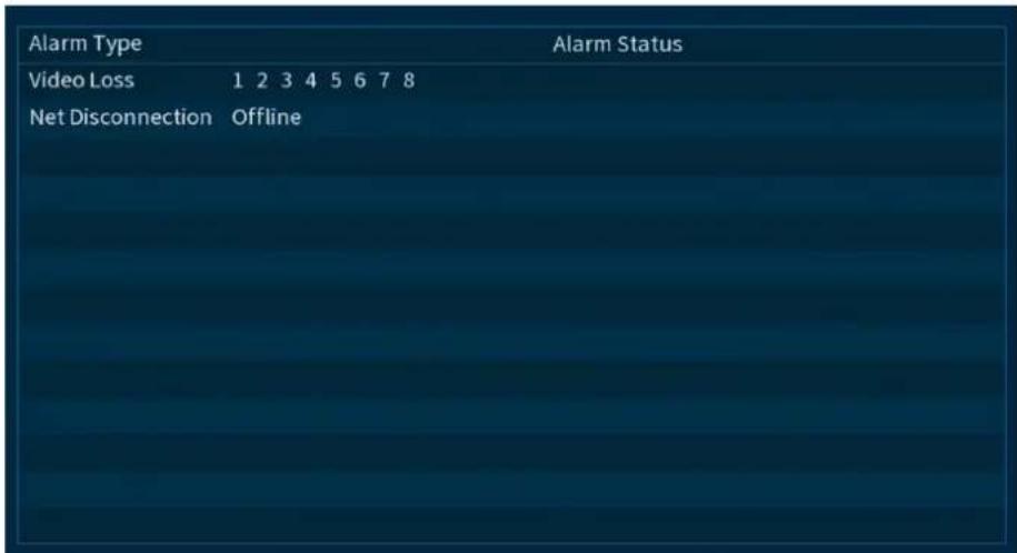
To access the Alarm Status menu:
- From the Live View display, right-click to open the Quick Menu, then click Main Menu.
- Click INFORMA TION, then click the Alarm Status tab.
The following alarms are shown in the Alarm Status menu:
• No HDD: No Hard drive is detected.
- Disk Error: Hard drive error detected.
- Disk Full: Hard drive is full.
- Net Disconnection: System is not connected to the network (offline).
- IP Conflict: More than one device on the network is using the same IP address.
• MAC Conflict: More than one device on the network is using the same MAC address.
• Video Loss: Shows disconnected channels.
• Motion: Shows channels with active motion alarms.
14.11.6 Online User
The Online User menu shows a list of users connected to the system using computers or mobile devices.

To access the Online User menu:
- From the Live View display, right-click to open the Quick Menu, then click Main Menu.
- Click INFORMA TION. Click the Network tab on the side panel, then Online User on the top panel.
14.11.7 Network Load
The Load menu shows you the network traffic your system is sending and receiving.
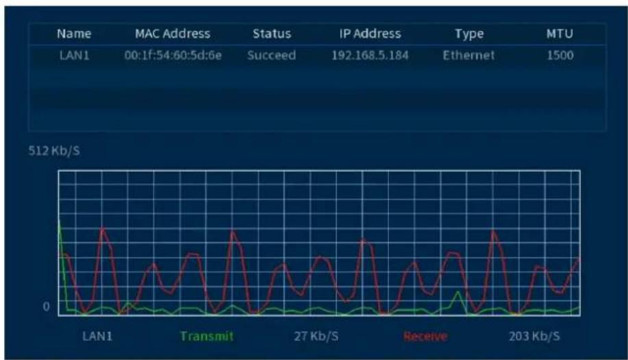
To access the Load menu:
- From the Live View display, right-click to open the Quick Menu, then click Main Menu.
- Click INFORMATION. Click the Network tab on the side panel, then Network Load on the top panel.
14.11.8 Test
The Test menu allows you to test if your system can connect to other devices over the LAN or Internet. You can enter the IP address of a device and click Test to determine if your system can connect to it.
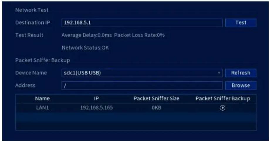
To access the Network Test menu:
- From the Live View display, right-click to open the Quick Menu, then click Main Menu.
- Click INFORMA TION. Click the Network tab on the side panel, then Test on the top panel.
14.11.9 Restoring Default Settings
Reset the system to default settings.
To restore default settings:
- From the Live View display, right-click to open the Quick Menu, then click Main Menu.
- Click INFORMA TION, click the Update/Reset tab, then click Default on the top panel.

- Click Default to reset all parameters to default settings, except for network, user management, and so on.
- Click Factory Default to reset the unit to its out-of-box state. The system will restart automatically. Do not power down the unit or disconnect the power cable.
14.11.10 Upgrading Firmware Manually
The primary method for upgrading system firmware is automatically over the Internet. The system also supports firmware upgrades from a USB thumb drive (not included).
Prerequisite:
- Save the .bin firmware file for your unit onto a USB flash drive (not included), and connect the drive to one of the system's free USB ports.
To upgrade firmware manually:
-
From the Live View display, right-click to open the Quick Menu, then click Main Menu.
-
Click INFORMATION, click the Update/Reset tab, then click Update on the top panel.
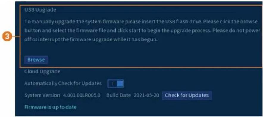
- Click Browse.
- Click on the .bin firmware file for your recorder.
- Click Start.
14.11.11 Automatic Firmware Upgrades
Firmware upgrades provide enhanced functionality. The system will automatically check for firmware upgrades if it is connected to the Internet.
To configure automatic firmware upgrade:
- From the Live View display, right-click to open the Quick Menu, then click Main Menu.
- Click INFORMA TION, click the Update/Reset tab, then click Update on the top panel.
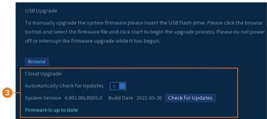
- Ensure Automatically Check for Updates is enabled (☐). Click Check for Updates to check if a newer version is available.
- If a newer version is found, click Upgrade Now to upgrade the system.
14.11.12 Save System Settings to a USB Flash Drive
The system allows you to save your current system configuration to a USB flash drive (not included). This is useful if you want to backup your current settings.

NOTE
This function only saves settings created in system menus. It does not save or backup any video.
Prerequisite:
- Connect a USB flash drive (not included) to a free USB port on the unit.
To save system settings:
- From the Live View display, right-click to open the Quick Menu, then click Main Menu.
- Click INFORMATION, click the Update/Reset tab.
- Click the Import/Export tab from the top panel.

- Under Device Name, select the USB device where you would like to save the configuration.
- Click Export to save your current system configuration.
14.11.13 Import System Settings from a USB Flash Drive
If you have backed up your system configuration, you can import it to apply all your saved menu settings.
Prerequisite:
- Connect a USB flash drive (not included) to a free USB port on the unit with an exported system configuration (see 14.11.12 Save System Settings to a USB Flash Drive, page 75 for full details).
To import system settings:
- From the Live View display, right-click to open the Quick Menu, then click Main Menu.
- Click INFORMA TION, click the Update/Reset tab, then click Import/Export on the top panel.
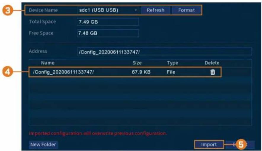
- Under Device Name, select the USB device where a system configuration has been saved.
- Click the folder with the configuration files you would like to restore. Configuration file folders are labeled Config and then the time and date the configuration was saved (e.g., Config_20200611133747).
- Click Import to save your current system configuration.
14.12 Copying Settings to Another Channel
Some areas of the main menu allow you quickly copy over the settings from one channel to one or multiple other channels on the system.
To copy channel settings:
- Configure at least one channel to your preference.
- Click Apply to save the settings for that channel.
- Click Copy.

- Click the numbered boxes to indicate the channels you want to copy settings to, or click All to copy to all channels.
- Click OK.
Connecting Remotely using the Lorex Home Mobile App
You can connect to your security system over the Internet using our free Lorex Home app for iOS and Android devices. Securely connect to your system from anywhere with no recurring fees for live viewing.

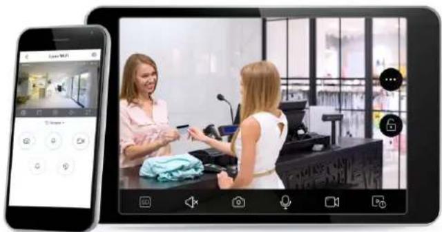
The Lorex Home app allows you to:
• View live video from cameras
- Play back recorded video from the hard drive
- Manually record video clips or take a snapshot of live video
- Activate deterrence features including warning lights and sirens*
- Set preferences for push notifications, informing you of motion detection and other system events
For full setup instructions and advanced support for the app, click here to open the Lorex Home instruction manual.
* On supporting devices.
Smart Home & Voice Assistance
The recorder is compatible with third-party smart home solutions, including Amazon Alexa® and Google Assistant®. You can use these services to take your security experience to the next level, with smart home options that make accessing your system even easier.
For compatibility information, as well as full instructions on setup and use, visit lorex.com/SmartHome.
To enable Smart Home services on the recorder:
- From the Live View display, right-click to open the Quick Menu, then click Main Menu.
- Click CAMERA, then click the Voice Assistance tab.

-
Click to enable (I) / disable (O) voice assistance.
-
Check channels you would like to enable for use with smart home services.

CAUTION
Channels enabled for use with smart home services will automatically enable the channel's audio functions, and will activate audio recording on audio-enabled cameras. Audio recording and / or use of listen-in audio without consent is illegal in certain jurisdictions. Lorex Corporation assumes no liability for use of its products that does not conform with local laws.
- Click Apply.
Pan/Tilt/Zoom (PTZ) Cameras
Pan/Tilt/Zoom (PTZ) cameras are specialty cameras that move according to commands given by the recorder. You can move PTZ cameras manually using the recorder's on-screen display, or create preset locations and patterns for the camera to follow automatically.

17.1 Connecting PTZ Cameras to the Recorder
Lorex HD PTZ cameras connect to your recorder just like any other camera with no need to run special wiring — these cameras can accept PTZ commands directly through the video cable.
If you are using a standard definition PTZ camera, you will need to run the camera's RS485 cabling to the recorder in order to send PTZ commands.
To connect standard definition PTZ cameras:
STEP 1: Physical connection
- Connect the BNC video cable to one of the video inputs on the recorder.
- Connect the RS485 cables. Connect the A (TX+) cable to the positive (+) terminal, and connect the B (TX-) cable to the negative (-) terminal.
- Connect the PTZ camera's power adapter to a power outlet.

CAUTION
When the PTZ camera powers on, it will perform an initial diagnostics check. The camera will move around during this process, so ensure the camera module is not resting against another object or surface.
STEP 2: Camera configuration
- From the Live View display, right-click to open the Quick Menu, then click Main Menu.
- Click CAMERA, then click the IMAGE SETTINGS tab.

-
Select the camera you want to configure.
-
Configure the highlighted fields as needed.

NOTE
For Lorex HD PTZ cameras, there is no need for configuration — leave all fields at their default values. For third-party PTZ cameras, select Serial next to Control Mode. For the correct settings to use in the remaining fields, please reference your camera documentation.
-
Click Apply.
-
(OPTIONAL) Click Copy to apply the settings for the current channel to one or more other channels (see 14.12 Copying Settings to Another Channel, page 77 for full instructions on using the copy function).

NOTE
If you copy settings over to connect multiple PTZ cameras, please note that each camera requires a unique address. You cannot use the same address for 2 different cameras.
17.2 Basic PTZ Controls
Controlling PTZ cameras.

NOTE
Ensure you have completed initial setup of your PTZ camera in order to control the camera using the recorder. See for more details.
To access the PTZ controls:
- Open the Live View screen for your PTZ camera in single-channel view (fullscreen). Right-click to open the Quick Menu, then click Pan/Tilt/Zoom.
• Right-click again to close PTZ controls.
To use the PTZ controls:

- Navigation Controls: Click the directional arrows to move the PTZ camera manually.
- Zoom-to-Area: Click, then click-and-drag to draw a box on the camera image. The PTZ camera will zoom in to the selected area.
- Mouse T racking: Click to enable/disable mouse tracking. When enabled, click-and-drag in the direction you would like the PTZ camera to move. The camera will follow the path of the mouse cursor.
- PTZ Settings:
- Speed: The speed of PTZ camera movement. A higher value means the camera will move faster.
- Zoom: Optical zoom level. Click + to zoom in, and - to zoom out.
- Focus: Manually control focus level. Click + to focus on objects further from the camera, or – to focus on objects closer to the camera.
- Iris: Controls the amount of light coming through the lens. Click + to allow more light, or – for less.
- Advanced: Expand to show advanced options. For a full overview, see 17.3 Advanced PTZ Controls, page 81.
17.3 Advanced PTZ Controls
Using advanced options for PTZ cameras, including presets, tours, patterns, etc.

NOTE
Ensure you have completed initial setup of your PTZ camera in order to control the camera using the recorder. See for more details.
To access the advanced PTZ controls:
- Open the Live View screen for your PTZ camera in single-channel view (fullscreen). Right-click to open the Quick Menu, then click Pan/Tilt/Zoom.
- Click the arrow on the far-right side of the PTZ control panel to access advanced options.
• Right-click again to close PTZ controls.
To use the PTZ controls:

- No.: Enter the ID number for a preset, tour, or pattern you want to activate.
- Preset: Move the camera to the preset number specified in the No. field. For instructions on setting up preset locations, see 17.4 Presets, page 82.
- AutoPan: Set the camera to rotate 180° back and forth.
- Tour: Perform the tour number specified in the No. field. For instructions on creating a tour, see 17.5 Tours, page 83.
- Flip: Rotate the camera 180° from its current position.
- Pattern: Perform the pattern number specified in the No. field. For instructions on creating a pattern, see 17.6 Patterns, page 83.
- Reset: Move the camera to the home position.
- AutoScan: Move the camera between a predetermined left and right point. For instructions on creating an autoscan, see 17.7 AutoScan, page 83.
- Configuration: Click to open the configuration menu, where you can configure presets, tours, patterns and autoscans.
- OSD Menu: Click to open the camera's OSD menu. This may not be supported on all camera models.
- Auxiliary Settings: Not supported.
17.4 Presets
Presets will save a camera position for quick retrieval.
To add preset locations:
- From the Live View display of your PTZ camera, right-click to open the Quick Menu, then click Pan/Tilt/Zoom.
- The PTZ controls open. Click ▶ to open advanced PTZ controls, then click
- Click the Preset tab.
- Enter the number of the preset you want to create under Preset.
- Move the camera to the desired position and click Set.
To go to a preset location:
• Under No., select the number of the preset you want to go to, then click

17.5 Tours
Tours will cycle through a set of presets.
To add tours:
- From the Live View display of your PTZ camera, right-click to open the Quick Menu, then click Pan/Tilt/Zoom.
- The PTZ controls open. Click ▶ to open advanced PTZ controls, then click
- Click the Tour tab.
- Under Patrol No., enter the number of the tour you want to create.
- Under Pre set, select a preset you want to add to the tour.
- Click Add Preset.
- Repeat steps 5 & 6 to add additional presets to the tour.
To run a tour:
• Under No., select the number of the tour you want to go to, then click
17.6 Patterns
Patterns automatically move the camera according to manually-entered movements.
To add patterns:
- From the Live View display of your PTZ camera, right-click to open the Quick Menu, then click Pan/Tilt/Zoom.
- The PTZ controls open. Click ▶ to open advanced PTZ controls, then click
- Click the Pattern tab.
- Under Pattern, enter the number of the pattern you want to create.
- Move the camera to the desired starting position, then click Start.
- Using the on-screen controls, move the camera in any pattern you wish. When finished, click End.
To run a pattern:
- Under No., select the number of the pattern you want to go to, then click

17.7 AutoScan
An autoscan automatically cycles between a left and right point.
To configure autoscan:
- From the Live View display of your PTZ camera, right-click to open the Quick Menu, then click Pan/Tilt/Zoom.
- The PTZ controls open. Click ▶ to open advanced PTZ controls, then click
- Click the Border tab.
- Move the camera into the desired left position and click Left.
- Move the camera into the desired right position and click Right.
To run autoscan:
- Click

Connecting Audio Devices
The system supports Lorex HD audio cameras, which transmit audio through the same coax cable used for video connection. The system can also record one audio channel using the AUDIO IN port on the rear panel. You must have a self-powered microphone or an audio camera with an RCA-type audio connection to use this port.

NOTE
Use of an external microphone allows you to record audio on Channel 1 of the system. It cannot be moved to a different channel.
The second RCA-type connector on the back panel is the AUDIO OUT port, which can be used to connect a self-powered speaker that will play audio from the system (requires audio-capable camera or self-power microphone).
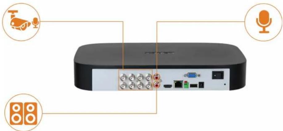
To enable audio recording using a Lorex HD audio camera:
- From the Live View display, right-click to open the Quick Menu, then click Main Menu.
- Click CAMERA . Click the RECORDING tab on the side panel, then Recording on the top panel.

-
Select the channel where the audio camera is connected.
-
Click Audio Setting, then configure the following:

- Audio Recording: Click to enable (I) / disable (O) audio recording.

CAUTION
Audio recording and / or use of listen-in audio without consent is illegal in certain jurisdictions. Lorex Corporation assumes no liability for use of its products that does not conform with local laws.
- Audio Format: Choose the desired format for audio recording (G711a or AAC recommended).
• Audio Source: Select HDCVI. -
Click OK.
-
Click Apply.
-
(OPTIONAL) Click Copy to apply the settings for the current channel to one or more other channels (see 14.12 Copying Settings to Another Channel, page 77 for full instructions on using the copy function).
To enable audio recording using an external microphone:
- From the Live View display, right-click to open the Quick Menu, then click Main Menu.
- Click CAMERA. Click the RECORDING tab on the side panel, then Recording on the top panel.
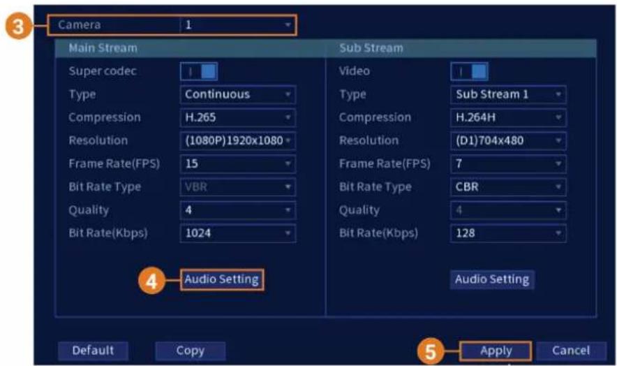
- Select Camera 1.

NOTE
Use of an external microphone allows you to record audio on Channel 1 of the system. It cannot be moved to a different channel.
- Click Audio Setting, then configure the following:
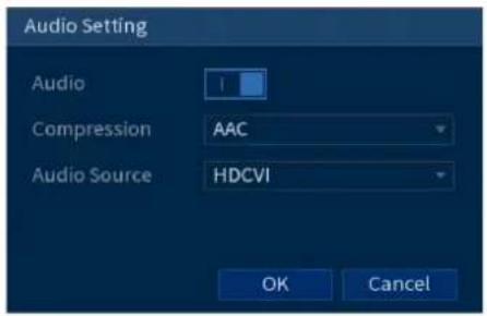
- Audio Recording: Click to enable (I) / disable (O) audio recording.

CAUTION
Audio recording and / or use of listen-in audio without consent is illegal in certain jurisdictions. Lorex Corporation assumes no liability for use of its products that does not conform with local laws.
- Audio Format: Choose the desired format for audio recording (G711a or AAC recommended).
• Audio Source: Select NORMAL. -
Click OK.
-
Click Apply.
Replacing the Hard Drive
The system comes with a pre-installed 3.5" SATA hard drive. You can replace the hard drive with one up to a maximum size of 16TB.
19.1 Removing the Hard Drive

CAUTION
Make sure that the system is OFF and the power adapter is disconnected before removing/installing a hard drive.
To remove the hard drive:
- Power off the system, and unplug all cabling from the system.
- Turn the recorder over. Remove the bottom panel screws (6×).

- Turn the recorder over carefully, then remove the top panel.

CAUTION
The wiring to the front panel button and USB port runs along the top panel of the recorder. When separating the top panel, rest it carefully beside the bottom panel as shown below.
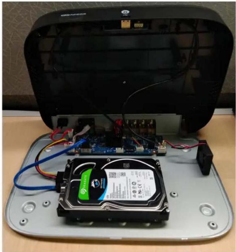
- Remove the power and SATA cables from the hard drive.
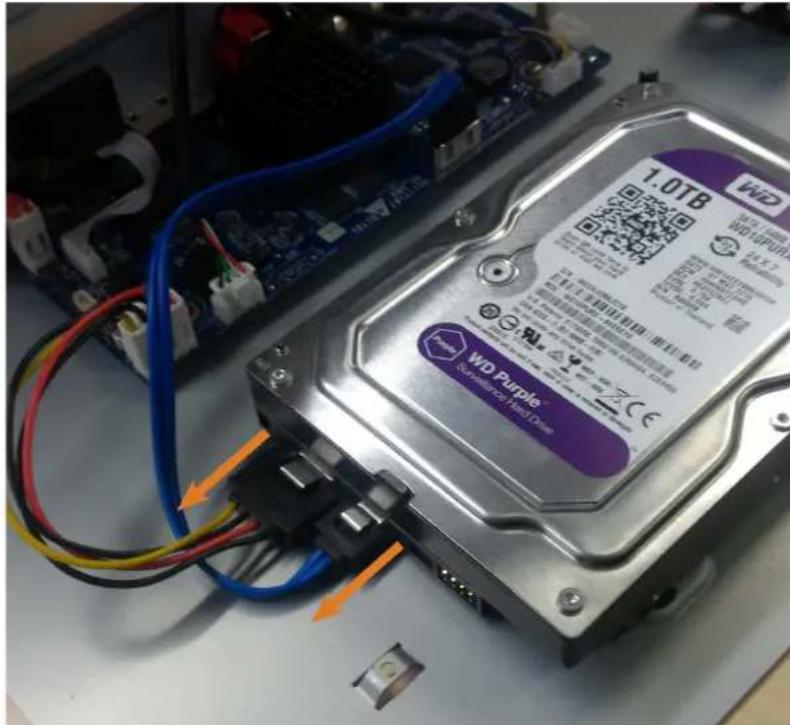
- Carefully pick up the hard drive to lift the bottom panel, being mindful of the sharp edges of the bottom panel. Remove the hard drive screws (4×) from the bottom panel. Hold onto the hard drive so it remains in place when all screws have been removed.

- If you are not immediately going to install a new hard drive, replace the top panel and the 6 bottom panel screws.
19.2 Installing a New Hard Drive
CAUTION
Make sure that the system is OFF and the power adapter is disconnected before removing/installing a hard drive.
To install a new hard drive:
- Insert the 2 hard drive screws closest to the SATA and power ports on the hard drive and tighten them half way.

-
Power off the system, and unplug all cabling from the system.
-
Turn the recorder over. Remove the bottom panel screws (6×).
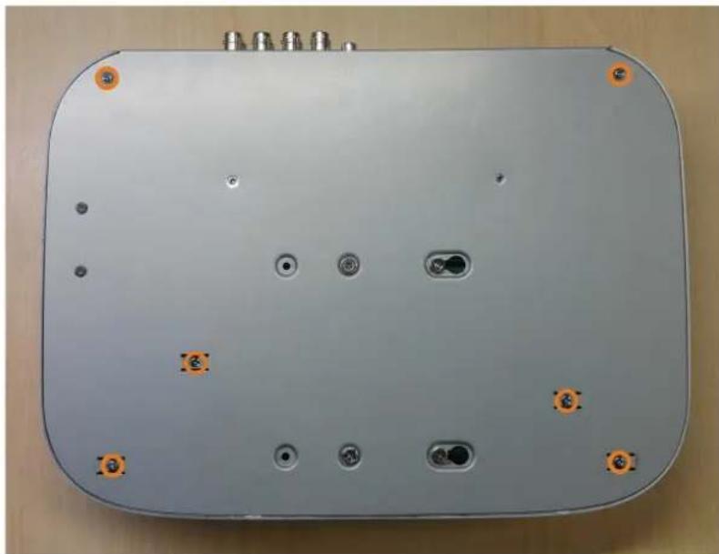
- Turn the recorder over carefully, then remove the top panel.

CAUTION
The wiring to the front panel button and USB port runs along the top panel of the recorder. When separating the top panel, rest it carefully beside the bottom panel as shown below.
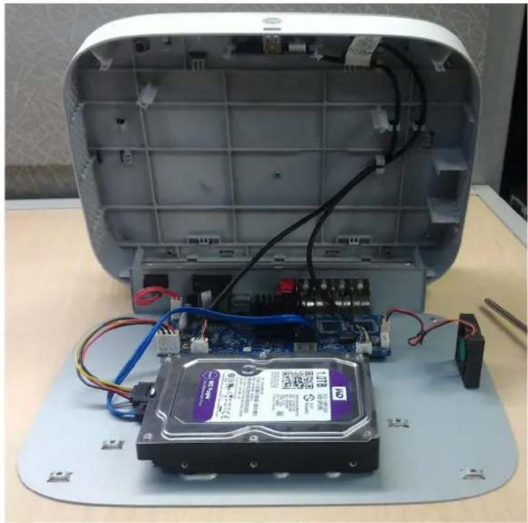
- Line the 2 half-inserted hard drive screws with the 2 holes shown below.

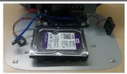
- Carefully pick up the bottom panel with the hard drive, being mindful of the sharp edges of the bottom panel. Slide the 2 pre-inserted screws into the locked position, then tighten the screws. Insert and tighten the 2 remaining hard drive screws.

- Connect the power and SATA cables to the hard drive.

- Replace the top panel and the 6 bottom panel screws.
DDNS Setup (Advanced)
Setting up DDNS connectivity allows you to view your recorder from any computer or compatible mobile device with Internet access.

NOTE
The primary connectivity option for the recorder uses the Lorex Home app to connect to your system over the Internet without the need for port forwarding or DDNS registration.
- For instructions on using the Lorex Home app for mobile devices, see 15 Connecting Remotely using the Lorex Home Mobile App, page 78.
20.1 STEP 1: Port Forwarding
If you are using DDNS, you must port forward the HTTP and Client Ports (default: 80 and 35000) on your router to your recorder's IP address before you can remotely connect to your system:
- Manually port forward the required ports on your router to your recorder's IP address by following your router manufacturer's instructions. For more information on port forwarding, see the reference guides on lorex.com.
20.2 STEP 2: Create a Lorex Account

- Visit lorex.com and click Login at the top of the page.

- Select Create an Account.
| NOTE |
| If you have already set up an account, select I Have a LOREX Account and log in. |
- Enter basic information for account setup.
- Click Create an Account.
20.3 STEP 3: Activate Your Warranty
Activate the manufacturer's warranty on your recorder.
To activate your product warranty:
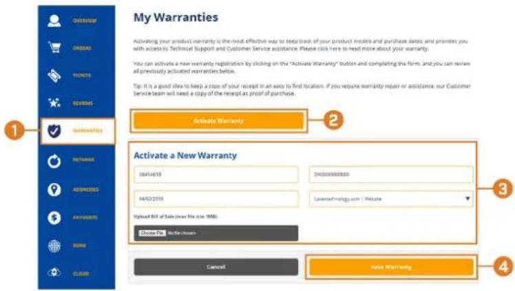
- From your Lorex account, click the WARRANTIES tab.
- Click Activate Warranty.
- Enter your product information (attaching bill of sale optional).
- Click Save Warranty.
Once submitted, your warranty information will be summarized under My Warranties.
20.4 STEP 4: Sign Up for a DDNS Account
Activate the manufacturer's warranty on your recorder.
To sign up for a DDNS account:

- From your Lorex account, click the DDNS tab.
-
Click Set up a New DDNS.
-
Select your recorder warranty from the dropdown next to Warranty. Enter the rest of your product information.

NOTE
- The Device Name can be any name of your choice (for example, "Store Security System").
- You can find your recorder's MAC Address in the system information window on the recorder. From
the Live View display, right-click and click Info, or click
on the Navigation Bar.

4. Click Add Device.
Once submitted, your DDNS account information will be summarized under My DDNS Devices. Make a note of your DDNS URL, Username and Password, as they will be needed to complete DDNS setup.
20.5 STEP 5: Enable DDNS on the Recorder
Enter your DDNS information into the menu of your recorder. You can find the information referenced below on your My Lorex account, or on the confirmation email sent to you after registering for DDNS service.
To configure DDNS in the recorder:
- From the Live View display, right-click to open the Quick Menu, then click Main Menu.
- Click NETWORK, then click the DDNS tab.

- Click to enable (1) DDNS connectivity.
- Configure the following:
• DDNS Type: Select Lorex DDNS.
- Domain Name: Enter the first part of the DDNS domain that you requested during setup.
- User ID: Enter the username provided in the DDNS confirmation email.
- Password: Enter the password provided in the DDNS confirmation email.
5. Click Apply.
You will now be able to access your system remotely using DDNS. Enter the full domain name into a web browser (e.g., http://www.tomsmithsecurity.lorexddns.net) and login using the provided credentials.

NOTE
If your system uses an IITTP port other than 80, you will need to add a colon to the end of your DDNS domain name and enter the port number (e.g., http://www.tomsmithsecurity.lorexddns.net:81)
21 Troubleshooting
When a malfunction occurs, it may not be serious or difficult to correct. The following chart contains solutions to most common problems. Please refer to the topics below before calling Lorex Technical Support.
| Error | Possible Causes | Solutions |
| System is not receiving power, or is not powering up. | Cable from power adapter is loose or is unplugged. | Confirm that all cables are connected correctly.Confirm that the power adapter is securely connected to the back of the unit. |
| Cables are connected, but system is not receiving sufficient power. | Confirm that the system is powered on (LED indicators on the front should be ON).If the unit is connected through a power bar or surge protector, try bypassing the bar and connecting the power directly to the wall outlet.Confirm that there is power at the outlet:Connect the power cable to another outlet.Test the outlet with another device (such as a lamp or phone charger). | |
| Hard drive is not detected by the system. | Hard drive cables are loose or not properly connected. | Remove the housing and check that hard drive cables are firmly connected. |
| There is no hard drive in the system. | Open the housing and install compatible hard drive. Make sure to format the drive after installing. For details, see 14.9.5 Formatting the Hard Drive, page 67. | |
| Hard drive is full (0%) and the unit is no longer recording. | Overwrite is not enabled. | If hard drive overwrite is not enabled, the system will stop recording when the hard drive is full. For instruction on enabling hard drive overwrite, see 8.5 Configuring Hard Drive Overwrite, page 20. |
| There is no picture on monitor/TV after connecting it to the recorder. | Monitor/TV not detected by recorder. | Power off the monitor/TV and the recorder. Power on the monitor/TV, and then power on the recorder. |
| Input channel for recorder not selected on monitor/TV. | Ensure that the monitor/TV is set to the input channel that the recorder is connected to. | |
| Video cable is loose or has become disconnected. | Check the video cable connection to the recorder and the monitor/TV. | |
| Camera is not compatible with the recorder. | Visit lorex.com/compatibility and navigate to D242 Series for a list of all compatible cameras. | |
| Mouse not detected by system. | Mouse cable is not firmly connected to the system, or the mouse is not connected to the system. | Firmly connect the mouse cable to one of the USB ports. |
| System needs to be reset. | Power off the system (disconnect power cable). Firmly connect a USB mouse to one of the USB ports. Reconnect the power cable to the 12V DC port on the rear panel. | |
| There is no picture on selected channels / camera picture is not being displayed. | Camera cables are loose or have become disconnected. | Check the camera video cable and connections.Disconnect and reconnect the cable at the system and at the camera.Try moving the camera to another channel or use another cable. |
| The image on the recorder appears, but does not have sound. | Cameras do not feature a microphone for audio recording. | The recorder supports audio recording, but requires audio-enabled cameras with a built-in microphone, or an external microphone to be connected. See 18 Connecting Audio Devices, page 84 for details on using audio-enabled devices. |
| The system beeps during motion detection. | Motion detection is enabled and the buzzer is activated. | See 11 Motion Detection, page 33 for full instructions on configuring motion detection options. You will need to uncheck the Buzzer option to prevent the recorder from beeping every time motion is detected. |
| I am not receiving email notifications. | Email notification is disabled. | Ensure you have configured email notification. For full instructions, see 14.7.3 Configuring Email Alerts, page 58. |
| Email notification is enabled, but you have not entered your own SMTP information. | If you want to use your own SMTP server, you must enter your SMTP server address, SMTP port, username, and password in the appropriate fields. For full instructions, see 14.7.3 Configuring Email Alerts, page 58. | |
| Smart home / voice assistance not working. | Voice assistance has not been enabled on the recorder. | Ensure you have enabled voice assistance on the recorder. See 16 Smart Home & Voice Assistance, page 79 for full instructions.If the issue persists, visit lorex.com/SmartHome for complete setup instructions, FAQs, and a list of available voice commands. |
22 Technical Specifications
22.1 General
| Video Transmission Technology | HD Analog |
| Channels 8 Channels |
22.2 Inputs/Outputs
| Video Input(s) | 16 × 1Vp-p, CVBS, 75ohms, BNC Type |
| Video Outputs(s) | 1 × VGA, 1 × HDMI |
| Audio Input(s) | 1 ch: RCA |
| Audio Output(s) | 1 ch: RCA |
22.3 Display
| Display Output Resolution | 1080p |
| Live Display | 1, 4, 8 |
| Live Display Speed (Max) | 480fps NTSC, 400fps PAL |
| OSD On/Off | |
| System Navigation | USB Mouse |
22.4 Recording
| Recording Resolution | 1080p, 720p 960H, D1, CIF |
| Recording Frame Rate | 1080p@15fps (NTSC); 720p/960/ D1/CIF@25/30fps (PAL/NTSC)2 |
| Recording Schedule | Per Channel by Continuous/Motion/Smart Motion (Person and Vehicle)/Alarm/Day/Hour |
| Back-up File Format | DAV / AVI / MP4 file |
| Video Compression | H.265 / H.264 |
22.5 Playback
| Simultaneous Playback | Up to 4 Channels |
| Playback Speed | Variable Max 16× |
| Search | By Time/Date, All Motion Events or Smart Motion (Person and Vehicle), (Smart Search) |
22.6 Storage
| Hard Drive Bays | 1 Bay |
| Hard Drive Capacity | Up to 1 × 16TB (SATA) |
| Backup Media | USB Flash Drive & USB IIDD |
22.7 Special Features
| Smart Motion Detection | Person and Vehicle Motion Detection (All Channels) |
| Smart Search | Yes |
| Active Deterrence Support | Yes |
| Panic Button Yes |
22.8 Smart Home
| Voice Control | Amazon AlexaTM, Google AssistantTM |
| Streaming Options | ChromecastTM, Apple TVTM Amazon Echo ShowTM, Google Home HubTM |
22.9 Connectivity
| Mobile Viewing | Android, iOS |
| Compatible App | Lorex HomeTM |
| PC/MAC Remote Viewing | Yes/Lorex CloudTM |
| Email Notification | Text and Snapshot |
| Network Interface | 10/100 Base-TX, RJ45 |
| DDNS | Yes (Optional) |
| USB Interface | USB 2.0 × 2 |
22.10 Additional Specifications
| FW Upgrade USB/Network | |
| Watchdog Function | Yes |
| Power Consumption | < 15W (without HDD) |
| Supply Voltage 12V/2A | |
| Unit Dimensions (W × D × H) | 12.9 × 9.6 × 2.1" (328× 245 × 53mm) |
| Unit Weight | 2.75lbs (1.26kg) (without HDD) |
| Operating Temperature | 14° ~ 131°F / -10° ~ 55°C |
| Humidity | 10 ~ 90% RH |
23 Notices
This product has been certified and found to comply with the limits regulated by FCC, EMC, and LVD. Therefore, it is designated to provide reasonable protection against interference and will not cause interference with other appliance usage. However, it is imperative that the user follows the guidelines in this manual to avoid improper usage, which may result in damage to the product, electrical shock and fire hazard injury.
23.1 FCC/IC
This equipment has been tested and found to comply with the limits for a digital device, pursuant to Part 15 of the FCC Rules. These limits are designed to provide reasonable protection against harmful interference in a residential or commercial installation. This equipment generates, uses, and can radiate radio frequency energy and, if not installed and used in accordance with the instruction manual, may cause harmful interference to radio communications.
23.2 CE
This product and the supplied accessories are marked with "CE" and comply with the applicable harmonized European standards listed under Low Voltage Directive 2006/95/EC and the EMC Directive 2004/108/EC.
23.3 Modification
Any changes or modifications not expressly approved by the grantee of this device could void the user's authority to operate the device.
This product is fully compliant with the European Union Restriction of the Use of Certain Hazardous Substances in Electrical and Electronic Equipment ("RoHS") Directive (2002/95/EC). The RoHS directive prohibits the sale of electronic equipment containing certain hazardous substances such as lead, cadmium, mercury, and hexavalent chromium, PBB, and PBDE in the European Union.
23.5 ICES-003
This device meets the CAN ICES-3 (A) / NMB-3 (A) standards requirements.
Website
www.lorextechnology.com
Copyright
© 2021, Lorex Corporation
All rights reserved worldwide. Names and marks appearing herein are either registered trademarks or trademarks of Lorex Corporation and/or its subsidiaries. All other trademarks, trade names or company names referenced herein are used for identification only and are the property of their respective owners.
Legal disclaimer
As our product is subject to continuous improvement, Lorex Corporation & subsidiaries reserve the right to modify product design, specifications & prices without notice and without incurring any obligation.E&OE.
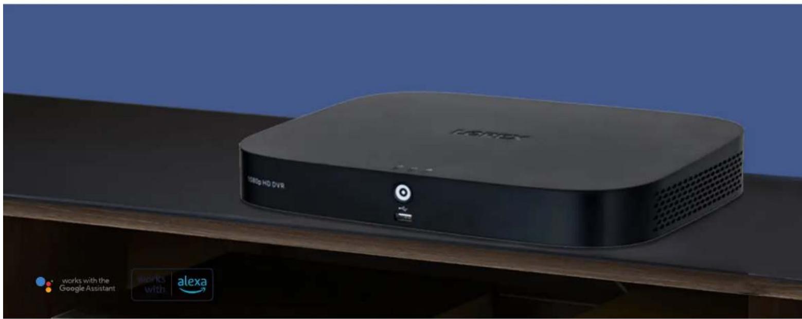
1080p Recording with Smart Motion Detection Technology
Record and view clear 1080p video with this powerful 8-channel recorder, providing Full HD resolution with impressive definition and detail. This recorder also features Smart Motion Detection, so you only receive alerts when someone is on your property. With convenient voice control and smart home compatibility, 1080p resolution and Smart Motion Detection, this recorder covers all the bases.
Resolution You Can Look Up To
High definition 1080p resolution
- Capable of recording up to 1080p Full HD Resolution on all cameras 1
• Digitally zoom in on distant objects for better clarity
Smart Motion Detection
Be alerted when a person or vehicle is on your property
- Reduce unnecessary alerts and false alarms with Smart Motion Detection 5
- Get smart push notifications when motion from a person or vehicle has been detected
- Use Smart Search to filter motion events for reviewing footage quickly and easily
- A panic button is located on the recorder to activate all lights and sirens with compatible cameras 9
No Fee Local Video Storage
Keep your footage private and secure
- Local built-in security-grade hard drive ensures only you can access your footage
• Supports up to an 8TB hard drive with no hidden monthly cloud fees - Heavy-duty hard drive designed to handle the workload of 24/7 monitoring
Operate with smart home features
Enjoy the convenience and control of smart home compatibility and voice control features
- Quickly access footage and features with simple voice commands (compatible with: Amazon Alexa™ and Google Assistant™) 4
• View live or recorded video directly on your TV with smart home compatibility (Compatible with: Apple TV™ and Chromecast™) 4 - Get push notifications through the Lorex Home app when motion from a person or vehicle has been detected
Features

1080p
Resolution

Person & Vehicle Local Private Smart Motion Detection Storage


Active Deterrence Support
Smart Home/Voice Control Compatible
Product Specifications
General
Video Transmission HD Analog Technology
Channels 8 Channels
Inputs/Outputs 7
Video Input(s) 8 × 1Vp-p, CVBS, 75ohms, BNC Type
Video Outputs(s) 1 × VGA, 1 × HDMI
Audio Input(s) 1 ch: RCA
Audio Output(s) 1 ch: RCA
Display
Display Output Resolution 1080p
Live Display 1,4,8
Live Display Speed (Max) 2 480fps NTSC, 400fps PAL
OSD On/Off
System Navigation USB Mouse
Recording
Recording Resolution 1080p, 720p 960H, D1, CIF
Recording Frame Rate 1080p@15fps (NTSC); 720p/960/D1/CIF@25/30fps (PAL/NTSC) 4
Recording Schedule Per Channel by, Continuous, Motion, Smart Motion (Person & Vehicle), Alarm, Day, Hour
Back-up File Format DAV/AVI/MP4 file
Video Compression H.265/H.264
Playback
Simultaneous Playback Up to 4 Channels
Playback Speed Variable Max 16×
Search By Time/Date, All Motion Events or Smart Motion (Person and Vehicle), (Smart Search)
Storage
Hard Drive Bays 1 Bay
Hard Drive Capacity 1 SATA port, up to 16 TB
Backup Media USB Flash Drive & USB HDD
Special Features
Smart Motion Detection Person and Vehicle Motion Detection (All Channels)
Smart Search Yes
Active Deterrence Yes Support
Panic Button Yes
Smart Home 8
Voice Control Amazon Alexa™, Google Assistant™
Streaming Options Chromecast™, Apple TV,™ Amazon Echo Show™, Google Home Hub™
Connectivity
Mobile Viewing Android, iOS
Compatible APP Lorex Home™
PC/Mac Remote Viewing Yes/Lorex Cloud™
Email Notification Text and Snapshot
Network Interface 10/100 Base-TX, RJ45
DDNS Yes (Optional)
USB interface USB 2.0 × 2
Additional Specifications
FW Upgrade USB/Network
Watchdog Function Yes
Power Consumption < 15W (Excl. HDD)
Supply Voltage 12V/2A
Unit Dimensions 12.9 × 9.6 × 2.1" / (W × D × H) 328 × 245 × 53mn
Unit Weight 2.75 lbs / 1.26Kg (Excl. HDD)
Operating Temperature 14° 131°F / -10° 55°C
Humidity 10 \~ 90% RH

Lorex Home

Model Information
D242A81B 8-channel 1080p DVR 6-95529-03518-5 with 1TB HDD
Dimensions
Package Plain Box
Package Weight 6.97lb / 3.16kg
Package Dimensions 15.43 × 13.07 × 5.31" / (W × D × H) 391 × 331 × 134mm
Package Cube 0.62cbf / 0.017cbm
Back Panels
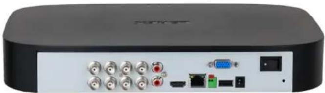
8 Channel Model
What's in the box

1 × 1080p DVR with 1 × HDMI Cable pre-installed 1TB HDD Adapter


1 × Ethernet cable

1 × DVR Power

1 × USB Mouse

Quick Setup Guide
Disclaimers:
-
Recording time may vary based on recording resolution & quality, lighting conditions and movement in the scene.
-
Accuracy of Smart Motion Detection or Person and Vehicle Detection will be influenced by multiple factors, such as the object's distance from the camera, the size of the object, and the height and angle of the camera. Night vision will also impact the accuracy of detection.
-
Compatible with select Lorex cameras only. For a list of compatible cameras, please visit www.lorex.com/compatibility
-
Controlling certain features in your security system requires a compatible smart device. Availability and performance of certain features and services are smart device dependent and may not be available.
-
Requires a high speed internet connection and a router (not included) for remote access. A minimum upload speed of 7.5Mbps is required for the best video performance. Up to 3 devices may connect to the system at the same time. For the latest list of supported apps and devices, please visit: www.lorex.com/support
-
Both firmware and software must be updated to latest version to ensure remote connectivity in all areas or networks. For compatibility, features, instructions visit: www.lorex.com/smarthome
-
HDMI output supports 1080p HD for high definition multi-channel live or recorded video viewing. Image quality and resolution is dependent on the type of camera connected to the DVR, as well as TV/monitor resolution
-
Apple TV ™ or Chromecast ™ need to be connected to the same network as your recorder. Requires Apple TV Gen 4 or newer with Lorex Home Apple TV APP or Chromecast ™ device connected to the TV that you want to view the system on.
All trademarks belong to their respective owners. No claim is made to the exclusive right to use the trademarks listed, other than the trademarks owned by Lorex Corporation. We reserve the right to change models, configurations or specifications without notice or liability. Product may not be exactly as shown.
Apple, the Apple logo and AppleTV are trademarks of Apple Inc., registered in the U.S. and other countries. App Store is a service mark of Apple Inc.
Google, Google Home, Google Play, Google Play logo, Google Assistant logo and Chromecast are trademarks of Google Inc.
Amazon, Alexa and all related logos are trademarks of Amazon.com, Inc. or its affiliates.
LOREX®
1080p MPX Bullet Security Camera
Quick Start Guide
English Version 1.0

LBV2531U SERIES
Package Contents
• 1080p MPX Bullet Security Camera
- Mounting Kit*
• BNC / Power Extension Cable*
- Power Adapter**
* Per camera in multi-camera packs.
** A multi-camera power adapter that provides power to multiple cameras or individual power adapters may be provided depending on product configuration.
ATTENTION:
A REGULATED UL / CSA APPROVED power supply is REQUIRED for use with this camera (included). Use of a non-regulated, non-conforming power supply can damage this product and voids the warranty.
Safety Precautions
- Read this guide carefully and keep it for future reference.
- Follow all instructions for safe use of the product and handle with care.
- Use the camera within given temperature, humidity and voltage levels noted in the camera's specifications.
- Do not disassemble the camera.
- Do not point the camera directly towards the sun or a source of intense light.
- Use only the supplied regulated power supply provided with the product. Use of a non-regulated, non-conforming power supply can damage the product and void the warranty.
- Periodic cleaning may be required. Use a damp cloth only. Do not use any harsh, chemical-based cleaners.
- The supplied cable is rated for surface mounting only. Cables for in-wall and floor-to-floor installations are sold separately (CMR type). These and other cables are available at lorex.com
Installation Tips
- Point the camera where there is the least amount of obstructions (i.e., tree branches).
• Install the camera where vandals cannot easily reach. - Secure cabling so that it is not exposed or easily cut.
- This camera is rated for outdoor use. Installation in a sheltered location is recommended.
Disclaimers
- For a full list of compatible recorders, visit lorex.com/compatibility
- Not intended for submersion in water. Installation in a sheltered location recommended.
Installing the Camera
ATTENTION:
Test your camera prior to selecting a permanent mounting location by temporarily connecting the camera and cable to your DVR.
Before Installing the Camera
- Decide whether to run the cables through the wall / ceiling (drilling required) or along the wall / ceiling.
- If you run the cables along the wall / ceiling, you must run the cable through the cable notch on the base. This will keep the camera base flush to the surface when mounted.
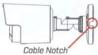
To install your camera:
- Set the camera in the desired mounting position and mark holes for screws through the camera base.
- Drill the holes, then feed the cable through the mounting surface or cable notch.
NOTE: Insert the included drywall anchors if you are mounting the camera onto drywall. - Mount the camera stand to the mounting surface using the provided screws. Make sure all screws are fastened tightly.
- Adjust the camera as shown below:

A. ROTATING THE ARM: Loosen the adjustment ring by turning it counter-clockwise. Rotate the arm of the camera up to 360°, then tighten the adjustment ring against the base.
B. BENDING THE ARM: Use a Phillips head screwdriver [not included] to loosen the adjustment screw closest to the camera base. Bend the arm of the camera up to 90°, then tighten the screw.
C. LEVELING THE CAMERA: Use the screwdriver to loosen the adjustment screw furthest from the camera base. Rotate the camera until it is level with the viewing area, then tighten the screw.
ATTENTION:
This camera includes an Auto Mechanical IR Cut Filter. When the camera changes between Day/Night viewing modes, an audible clicking noise may be heard from the camera. This clicking is normal, and indicates that the camera filter is working.
Connecting the Camera

Camera

Connect the male power head and the BNC connector to the camera.
Connect the BNC connector to a video input on your DVR.
DVR
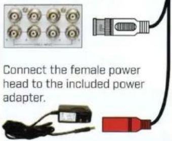
* Images for representation only.
Power Adapter Types
A multi-camera power adapter that provides power to multiple cameras or individual power adapters may be provided, depending on product configuration.
Individual Power Adapter*

* Images for representation only.
Multi-Camera Power Adapter*

Setup Diagram

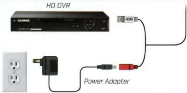
Cable Extension Options
Extend the cable run for your camera depending on the cable type used. Additional extension cables sold separately. See table below:
| Option | Cable Type | Max Cable Run Distance |
| 1 | BNC cable included with the camera | 60ft (18m) |
| 2 | ‘RG59’ or ‘Coax’ or ‘Coaxial BNC’ Siamese [Video and Power] | 300ft (92m) |
| 3 | ‘RG59’ or ‘Coax’ or ‘Coaxial BNC’ [Video Only] 2 | 800ft (242m) |
Notes:
- The extension cable must be a single stretch of cable between the DVR and camera. You cannot connect multiple extension cables to each other.
- For cable runs above 300ft / 92m (option 3), you must connect the power adapter directly to the camera, rather than at the end of the extension cable.
- Indicators that your cable run may be too long:
• Camera loses video when switching to night vision
• Video is permanently black & white (even during day time)
• Video is unclear, soft, or distorted - For more information on extension cables, visit lorex.com
Troubleshooting
| Problem | Solution |
| No picture / signal | The cameras are only compatible with certain Lorex HD DVRs. For the full list of compatible recorders, visitlorex.com/compatibilityEnsure your TV or monitor is on the correct input channel. Common terms for input channels: INPUT, AV CHANNEL, LINE1, LINE2, AUX.Ensure your DVR is properly connected to your TV or monitor.Ensure connections are properly connected.Ensure the camera power supply is plugged in.Ensure that you only use the included power cable. |
| Picture is too bright | Ensure your camera isn't pointed directly at a source of light (e.g., sun or spot light).Check the brightness settings of the DVR and monitor.Move your camera to a different location. |
| Picture is too dark | Check the brightness and contrast settings of the DVR and monitor. |
| Night vision is not working | The night vision activates when light levels drop. The area may have too much light. |
| Picture is not clear | Check the camera lens for dirt, dust, spiderwebs. Clean the lens with a soft, clean cloth.Make sure that the cable run is within the limitations specified in the section 'Cable Extension Options'. |
| Bright spot in video when viewing camera at night | Night vision reflects when pointing a camera through a window. Move the camera to a different location. |
Resources
Need Help?
Visit us online for up-to-date software and complete instruction manuals

1
Visit lorex.com
2
Search for the model number of your product
3
Click on your product in the search results
4
Click on the Downloads tab
Dimensions


Copyright © 2018 Lorex Corporation
As our products are subject to continuous improvement, Lorex reserves the right to modify product design, specifications and prices, without notice and without incurring any obligation. E&OE. All rights reserved.
LOREX®
Thank you for purchasing a Lorex product.
Please see our full Terms of Service and Limited Hardware Warranty Policy at:
The regulatory information herein might vary according to the model you purchased. Some information is only applicable for the country or region where the product is sold.
FCC Information

CAUTION
Changes or modifications not expressly approved by the party responsible for compliance could void the user's authority to operate the equipment.
FCC conditions:
This device complies with part 15 of the FCC Rules. Operation is subject to the following two conditions:
• This device may not cause harmful interference.
- This device must accept any interference received, including interference that may cause undesired operation.
FCC compliance:
This equipment has been tested and found to comply with the limits for a digital device, pursuant to part 15 of the FCC Rules. This equipment generates, uses, and can radiate radio frequency energy and, if not installed and used in accordance with the instructions, may cause harmful interference to radio communication.
- For class A device, these limits are designed to provide reasonable protection against harmful interference in a commercial environment. Operation of this equipment in a residential area is likely to cause harmful interference in which case the user will be required to correct the interference at his own expense.
- For class B device, these limits are designed to provide reasonable protection against harmful interference in a residential installation. However, there is no guarantee that interference will not occur in a particular installation. If this equipment does cause harmful interference to radio or television reception, which can be determined by turning the equipment off and on, the user is encouraged to try to correct the interference by one or more of the following measures:
• Reorient or relocate the receiving antenna.
- Increase the separation between the equipment and receiver.
- Connect the equipment into an outlet on a circuit different from that to which the receiver is connected.
- Consult the dealer or an experienced radio/TV technician for help.
Declaration of Conformity UKCA
UKCA
This device complies with UKCA relevant directives and standards. UK Declaration of Conformity (DoC) can be downloaded from: https://www.lorex.com/pages/ukca-compliance
Lorex Technology UK Limited
1 Georges Square, Bath Street, Bristol, United Kingdom, BS1 6BA.
Battery Replacement and Disposal
Applicable to products with battery.

CAUTION
Risk of explosion if battery is replaced by an incorrect type. Dispose of used batteries according to the instructions.
Privacy Protection Notice
As the device user or data controller, you might collect personal data of others such as face, fingerprints, car plate number, Email address, phone number, GPS and so on. You need to be in compliance with the local privacy protection laws and regulations to protect the legitimate rights and interests of other people by implementing measures include but not limited to: providing clear and visible identification to inform data subject the existence of surveillance area and providing related contact
For full FCC compliance declarations, visit https://www.lorex.com/pages/fcc-compliance
- SETUP
- REMOTE VIEWING
- PACKAGE CONTENTS AND DIMENSIONS
- BACK PANEL OVERVIEW
- SETUP STEP 1 — CONNECT CAMERAS
- TO CONNECT CAMERAS DIRECTLY TO THE DVR
- NOTES
- SETUP STEP 2 — CONNECT ROUTER
- SETUP STEP 3 — CONNECT MOUSE
- SETUP STEP 4 — CONNECT MONITOR/TV
- SETUP STEP 5 — CONNECT POWER
- SETUP STEP 6 — LOREX SETUP WIZARD
- QUICK ACCESS TO SYSTEM INFORMATION
- USING THE MOUSE
- USING THE QUICK MENU
- MOTION AND SMART MOTION DETECTION
- TO CONFIGURE MOTION AND SMART MOTION DETECTION SETTINGS
- USING DETERRENCE FEATURES
- TO CONFIGURE DETERRENCE SETTINGS
- TO MANUALLY ACTIVATE THE WARNING LIGHT AND/OR SIREN FEATURES
- CHANGING THE RECORDER'S OUTPUT RESOLUTION
- TO CHANGE THE RECORDER'S OUTPUT RESOLUTION
- PLAYBACK AND SEARCH
- TO SEARCH FOR AND PLAY RECORDINGS
- BACKUP
- TO BACK UP RECORDINGS
- REMOTE VIEWING — BEFORE YOU START
- MAKE SURE THAT YOU HAVE
- REMOTE VIEWING — CONNECT TO THE APP
- REMOTE VIEWING — LOREX HOME APP LIVE VIEW
- NEED HELP
- USER MANUAL D242 SERIES
- WARNING
- TABLE OF CONTENTS
- 1 IMPORTANT SAFEGUARDS .... 1
- 2 PACKAGE CONTENTS....4
- 3 RECORDER OVERVIEW 5
- 4 BASIC SYSTEM SETUP....6
- 5 CAMERA INSTALLATION....10
- 6 USING THE MOUSE ....13
- 7 USING THE ON-SCREEN DISPLAY....14
- 8 RECORDING....17
- 9 PLAYBACK....22
- 10 BACKUP....28
- 11 MOTION DETECTION ....33
- 12 ACTIVE DETERRENCE....37
- 13 MANAGING PASSWORDS AND USER ACCOUNTS ....40
- 14 USING THE MAIN MENU....45
- 1 IMPORTANT SAFEGUARDS
- 1.1 GENERAL PRECAUTIONS
- CAUTION
- 1.2 INSTALLATION
- 1.3 SERVICE
- 1.4 USE
- 2 PACKAGE CONTENTS
- 3 RECORDER OVERVIEW
- 3.1 FRONT PANEL
- LED INDICATORS
- INFO / PANIC BUTTON
- 3.2 BACK PANEL
- NOTE
- BASIC SYSTEM SETUP
- 4.1 STEP 1: CONNECT CAMERAS
- 4.2 STEP 2: CONNECT ROUTER
- 4.3 STEP 3: CONNECT MOUSE
- 4.4 STEP 4: CONNECT MONITOR
- OR
- 4.5 STEP 5: CONNECT POWER
- 4.6 STEP 6: LOREX SETUP WIZARD
- 4.7 STEP 7: UPGRADE FIRMWARE TO LATEST VERSION (IF AVAILABLE)
- IF A FIRMWARE UPGRADE IS AVAILABLE
- 4.8 QUICK ACCESS TO SYSTEM INFORMATION
- CAMERA INSTALLATION
- 5.1 INSTALLATION TIPS
- 5.2 ENSURING ACCURATE PERSON AND VEHICLE DETECTION
- 5.3 INSTALLING CAMERAS
- 5.4 CONNECTING CAMERA EXTENSION CABLES
- 6 USING THE MOUSE
- LEFT-BUTTON
- RIGHT-BUTTON
- USING THE ON-SCREEN DISPLAY
- 7.1 NAVIGATION BAR
- TO SHOW THE NAVIGATION BAR
- 7.2 QUICK MENU
- 7.3 CAMERA TOOLBAR
- 7.4 ON-SCREEN KEYPADS
- TO USE THE FULL KEYPAD
- TO USE THE NUMBER KEYPAD
- RECORDING
- 8.1 VIDEO RECORDING TYPES
- 8.2 CONFIGURING RECORDING QUALITY
- TO CONFIGURE RECORDING QUALITY
- CLICK APPLY
- 8.3 SETTING THE RECORDING SCHEDULE
- TO CONFIGURE THE RECORDING SCHEDULE
- 8.4 SETTING UP SCHEDULED OR MANUAL RECORDING
- TO SET OPTIONS FOR MANUAL RECORDING
- 8.5 CONFIGURING HARD DRIVE OVERWRITE
- TO CONFIGURE HARD DRIVE OVERWRITE
- PLAYBACK
- 9.1 PLAYING BACK VIDEO FROM THE HARD DRIVE
- TO PLAY BACK RECORDED VIDEO
- 9.2 PLAYBACK CONTROLS
- VIEWING MODES
- PLAYBACK CONTROLS
- 9.3 PLAYING BACK VIDEO FROM A USB DRIVE
- TO PLAY BACK VIDEO FROM A USB FLASH DRIVE
- 9.4 SMART SEARCH
- TO PERFORM A SMART SEARCH
- 9.5 VIDEO CLIP BACKUP
- TO USE VIDEO CLIP BACKUP
- 10.1 FORMATTING THE USB FLASH DRIVE
- PREREQUISITE
- TO FORMAT A USB FLASH DRIVE
- 10.2 BACKING UP VIDEO
- TO BACKUP VIDEO
- CLICK BACKUP
- CONFIGURE THE FOLLOWING
- 10.3 USING VIDEO CLIP BACKUP
- 10.4 VIEWING BACKED UP FILES
- 10.4.1 VIEWING BACKED UP FILES ON PC
- 10.4.2 VIEWING BACKED UP FILES ON MAC
- 10.4.3 LOREX PLAYER CONTROLS
- ZOOM TIMELINE
- 11 MOTION DETECTION
- 11.1 CONFIGURING MOTION DETECTION
- TO CONFIGURE MOTION DETECTION
- 11.2 SEARCH FOR PERSON AND VEHICLE DETECTION EVENTS
- TO SEARCH FOR PERSON AND VEHICLE DETECTION EVENTS
- 12 ACTIVE DETERRENCE
- 12.1 AUTOMATIC DETERRENCE SETTINGS
- 12.2 MANUALLY ACTIVATE DETERRENCE FEATURES
- TO ACTIVATE DETERRENCE FEATURES ON A SINGLE CAMERA
- TO ACTIVATED DETERRENCE FEATURES ON ALL CONNECTED CAMERAS
- MANAGING PASSWORDS AND USER ACCOUNTS
- 13.1 USER ACCOUNTS
- 13.1.1 CHANGING PASSWORDS
- TO CHANGE AN ACCOUNT PASSWORD
- CLICK OK
- 13.1.2 ADDING USERS
- TO ADD A USER
- CLICK ADD USER
- 13.1.3 MODIFYING USERS
- TO MODIFY A USER
- 13.1.4 DELETING USERS
- TO REMOVE A USER
- 13.2 ACCOUNT GROUPS
- THE SYSTEM INCLUDES THE FOLLOWING GROUPS BY DEFAULT
- 13.2.1 ADDING GROUPS
- TO ADD A GROUP
- 13.2.2 MODIFYING GROUPS
- TO MODIFY A GROUP
- 13.2.3 DELETING GROUPS
- TO DELETE A GROUP
- USING THE MAIN MENU
- TO ACCESS THE MAIN MENU
- 14.1 MAIN MENU'S NAVIGATION BAR
- TO SHOW THE MAIN MENU NAVIGATION BAR
- 14.2 PLAYBACK
- 14.3 EVENTS
- 14.3.1 VIDEO LOSS
- TO CONFIGURE VIDEO LOSS SETTINGS
- 14.3.2 SYSTEM WARNINGS
- TO SET PREFERENCES FOR HARD DRIVE EVENTS
- TO SET PREFERENCES FOR NETWORK EVENTS
- 14.3.3 SEARCHING EVENT LOGS
- TO SEARCH FOR EVENTS
- 14.4 BACKUP
- 14.5 DISPLAY
- 14.5.1 SETTING THE RECORDER'S OUTPUT RESOLUTION
- TO CHANGE THE OUTPUT RESOLUTION
- 14.5.2 LISTEN-IN AUDIO
- TO SET PREFERENCES FOR LISTEN-IN AUDIO
- 14.5.3 MENU T TRANSPARENCY
- TO SET MENU TRANSPARENCY
- 14.5.4 GENERAL DISPLAY SETTINGS
- TO CONFIGURE GENERAL DISPLAY SETTINGS
- 14.5.5 CONFIGURING SEQUENCE MODE
- TO CONFIGURE SEQUENCE MODE
- 14.6 CAMERA
- 14.6.1 ADJUSTING CAMERA IMAGE SETTINGS
- 14.6.2 CONFIGURING SNAPSHOT RECORDING
- TO CONFIGURE SNAPSHOT RECORDING
- 14.6.3 CHANGING ON-SCREEN OVERLAY
- TO CHANGE THE ON-SCREEN OVERLAY
- 14.6.4 CONFIGURING PRIVACY MASKING
- TO CONFIGURE PRIVACY MASKING
- 14.6.5 CONNECTING MULTI-FORMAT CAMERAS (CABLE TYPE)
- TO MANUALLY CHANGE THE CAMERA FORMAT
- 14.6.6 CAMERA FIRMWARE UPGRADE (CVI UPGRADE)
- TO MANUALLY UPGRADE CAMERA FIRMWARE
- 14.7 NETWORK
- 14.7.1 SELECTING DHCP OR STATIC IP ADDRESS (TCP/IP)
- TO CONFIGURE BASIC NETWORKING SETTINGS
- CONFIGURE THE FOLLOWING SETTINGS
- 14.7.2 CONFIGURING SYSTEM PORTS (CONNECTION)
- TO CONFIGURE SYSTEM PORTS
- 14.7.3 CONFIGURING EMAIL ALERTS
- TO CONFIGURE EMAIL ALERTS
- IF YOU WANT TO USE LOREX'S EMAIL SERVER (RECOMMENDED)
- IF YOU WANT TO USE YOUR OWN EMAIL SERVER (ADVANCED)
- 14.7.4 P2P SETTING
- TO CHANGE P2P SETTING
- 14.8 SYSTEM
- 14.8.1 CONFIGURING GENERAL SYSTEM SETTINGS
- TO CONFIGURE GENERAL SYSTEM SETTINGS
- 14.8.2 SETTING DATE & TIME
- TO SET SYSTEM DATE AND TIME
- CONFIGURE SYSTEM TIME
- 14.8.3 CONFIGURING HOLIDAYS
- TO CONFIGURE HOLIDAYS
- CLICK ADD
- 14.8.4 CONFIGURING IP FILTER
- TO CONFIGURE THE IP FILTER
- 14.8.5 CONFIGURING IP FILTER — SYNC TIME
- 14.9 STORAGE
- 14.9.1 CONFIGURING HARD DRIVE OVERWRITE
- 14.9.2 CONFIGURING RECORDING FILE LENGTH
- TO CONFIGURE RECORDING LENGTH
- 14.9.3 CONFIGURING PRE-RECORDING
- TO CONFIGURE PRE-RECORDING
- 14.9.4 SETTING THE SNAPSHOT SCHEDULE
- TO SET THE SNAPSHOT SCHEDULE
- 14.9.5 FORMATTING THE HARD DRIVE
- TO FORMAT HARD DRIVES
- 14.9.6 CONFIGURING HARD DRIVE TYPE
- TO CONFIGURE HARD DRIVE TYPES
- 14.9.7 RECORDING CALCULATOR (REC ESTIMATE)
- TO OBTAIN A RECORDING ESTIMATE
- 14.9.8 FTP (ADVANCED)
- TO CONFIGURE FTP SETTINGS
- 14.10 ACCOUNT
- 14.11 INFORMATION
- 14.11.1 VERSION
- TO ACCESS THE VERSION MENU
- 14.11.2 DISK
- TO ACCESS THE DISK MENU
- 14.11.3 BPS
- TO ACCESS THE BPS MENU
- 14.11.4 LOG
- TO SEARCH FOR SYSTEM LOGS
- 14.11.5 ALARM STATUS
- TO ACCESS THE ALARM STATUS MENU
- THE FOLLOWING ALARMS ARE SHOWN IN THE ALARM STATUS MENU
- 14.11.6 ONLINE USER
- TO ACCESS THE ONLINE USER MENU
- 14.11.7 NETWORK LOAD
- TO ACCESS THE LOAD MENU
- 14.11.8 TEST
- TO ACCESS THE NETWORK TEST MENU
- 14.11.9 RESTORING DEFAULT SETTINGS
- TO RESTORE DEFAULT SETTINGS
- 14.11.10 UPGRADING FIRMWARE MANUALLY
- TO UPGRADE FIRMWARE MANUALLY
- 14.11.11 AUTOMATIC FIRMWARE UPGRADES
- TO CONFIGURE AUTOMATIC FIRMWARE UPGRADE
- 14.11.12 SAVE SYSTEM SETTINGS TO A USB FLASH DRIVE
- TO SAVE SYSTEM SETTINGS
- 14.11.13 IMPORT SYSTEM SETTINGS FROM A USB FLASH DRIVE
- TO IMPORT SYSTEM SETTINGS
- 14.12 COPYING SETTINGS TO ANOTHER CHANNEL
- TO COPY CHANNEL SETTINGS
- CONNECTING REMOTELY USING THE LOREX HOME MOBILE APP
- THE LOREX HOME APP ALLOWS YOU TO
- SMART HOME & VOICE ASSISTANCE
- TO ENABLE SMART HOME SERVICES ON THE RECORDER
- PAN/TILT/ZOOM (PTZ) CAMERAS
- 17.1 CONNECTING PTZ CAMERAS TO THE RECORDER
- STEP 1: PHYSICAL CONNECTION
- STEP 2: CAMERA CONFIGURATION
- 17.2 BASIC PTZ CONTROLS
- TO ACCESS THE PTZ CONTROLS
- 17.3 ADVANCED PTZ CONTROLS
- TO ACCESS THE ADVANCED PTZ CONTROLS
- TO USE THE PTZ CONTROLS
- 17.4 PRESETS
- TO ADD PRESET LOCATIONS
- TO GO TO A PRESET LOCATION
- 17.5 TOURS
- TO ADD TOURS
- TO RUN A TOUR
- 17.6 PATTERNS
- TO ADD PATTERNS
- TO RUN A PATTERN
- 17.7 AUTOSCAN
- TO CONFIGURE AUTOSCAN
- TO RUN AUTOSCAN
- CONNECTING AUDIO DEVICES
- TO ENABLE AUDIO RECORDING USING A LOREX HD AUDIO CAMERA
- TO ENABLE AUDIO RECORDING USING AN EXTERNAL MICROPHONE
- REPLACING THE HARD DRIVE
- 19.1 REMOVING THE HARD DRIVE
- TO REMOVE THE HARD DRIVE
- 19.2 INSTALLING A NEW HARD DRIVE
- TO INSTALL A NEW HARD DRIVE
- DDNS SETUP (ADVANCED)
- 20.1 STEP 1: PORT FORWARDING
- 20.2 STEP 2: CREATE A LOREX ACCOUNT
- 20.3 STEP 3: ACTIVATE YOUR WARRANTY
- 20.4 STEP 4: SIGN UP FOR A DDNS ACCOUNT
- CLICK ADD DEVICE
- 20.5 STEP 5: ENABLE DDNS ON THE RECORDER
- TO CONFIGURE DDNS IN THE RECORDER
- 21 TROUBLESHOOTING
- 22 TECHNICAL SPECIFICATIONS
- 23 NOTICES
- 23.1 FCC/IC
- 23.2 CE
- 23.3 MODIFICATION
- 23.5 ICES-003
- WEBSITE
- COPYRIGHT
- LEGAL DISCLAIMER
- 1080P RECORDING WITH SMART MOTION DETECTION TECHNOLOGY
- RESOLUTION YOU CAN LOOK UP TO
- HIGH DEFINITION 1080P RESOLUTION
- SMART MOTION DETECTION
- BE ALERTED WHEN A PERSON OR VEHICLE IS ON YOUR PROPERTY
- NO FEE LOCAL VIDEO STORAGE
- KEEP YOUR FOOTAGE PRIVATE AND SECURE
- OPERATE WITH SMART HOME FEATURES
- ENJOY THE CONVENIENCE AND CONTROL OF SMART HOME COMPATIBILITY AND VOICE CONTROL FEATURES
- FEATURES
- PRODUCT SPECIFICATIONS
- GENERAL
- INPUTS/OUTPUTS 7
- DISPLAY
- STORAGE
- SPECIAL FEATURES
- SMART HOME 8
- CONNECTIVITY
- ADDITIONAL SPECIFICATIONS
- MODEL INFORMATION
- DIMENSIONS
- BACK PANELS
- WHAT'S IN THE BOX
- LOREX®
- PACKAGE CONTENTS
- ATTENTION
- SAFETY PRECAUTIONS
- INSTALLATION TIPS
- DISCLAIMERS
- INSTALLING THE CAMERA
- BEFORE INSTALLING THE CAMERA
- TO INSTALL YOUR CAMERA
- POWER ADAPTER TYPES
- CABLE EXTENSION OPTIONS
- RESOURCES
- FCC INFORMATION
- FCC CONDITIONS
- FCC COMPLIANCE
- DECLARATION OF CONFORMITY UKCA
- UKCA
- BATTERY REPLACEMENT AND DISPOSAL
- PRIVACY PROTECTION NOTICE
Brand : Lorex
Model : D24281B-2NA4-E
Category : Video recorder