PC20 - Multimeter Sanwa - Free user manual and instructions
Find the device manual for free PC20 Sanwa in PDF.


| Product Type | Digital Multimeter |
| Brand | Sanwa |
| Model | PC20 |
| Display | 4000 counts LCD |
| Measurement Functions | DCV, ACV, DCA, ACA, Resistance, Diode test, Continuity, Capacitance, Temperature (with optional T-300PC) |
| DC Voltage Ranges | 400 mV, 4 V, 40 V, 400 V, 1000 V |
| AC Voltage Ranges | 4 V, 40 V, 400 V, 750 V |
| DC Current Ranges | 400 µA, 4000 µA, 40 mA, 400 mA, 4 A, 10 A |
| AC Current Ranges | 400 µA, 4000 µA, 40 mA, 400 mA, 4 A, 10 A |
| Resistance Ranges | 400 Ω, 4 kΩ, 40 kΩ, 400 kΩ, 4 MΩ, 40 MΩ |
| Capacitance Ranges | 50 nF, 500 nF, 5 µF, 50 µF, 100 µF (auto range only) |
| Temperature Range (with optional probe) | -50°C to 300°C |
| Power Supply | 2 x R6 (AA) dry batteries |
| Battery Life | Approx. 150 hours (DCV) |
| Dimensions | 167 (H) x 90 (W) x 48 (D) mm |
| Weight | Approx. 330 g (with holster) |
| Fuse Ratings | 0.5 A/250 V (5x20 mm), 12.5 A/250 V (6.3x32 mm) |
| Safety Specifications | Max input: DC 1000 V, AC 750 V; Pollution degree 2; Indoor use |
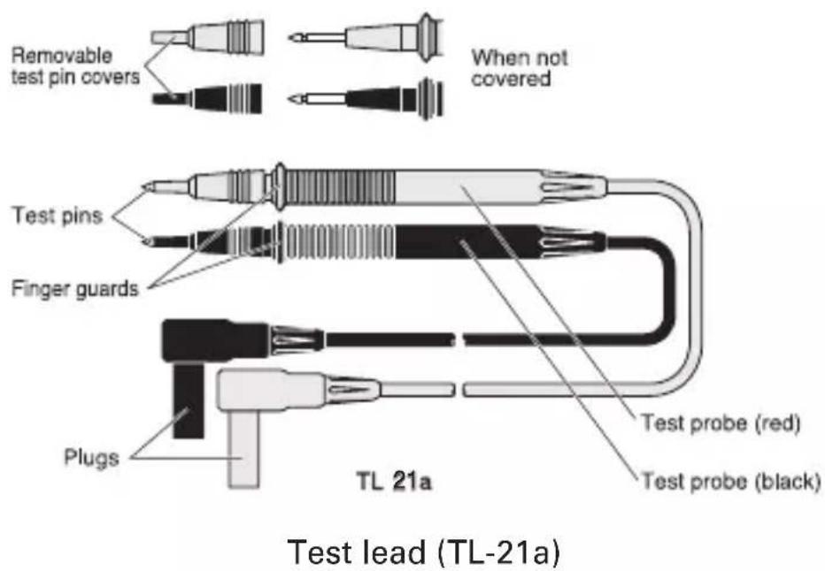
| Accessories Included | Test leads (TL-21a), Holster (H-70), Instruction manual |
| Optional Accessories | AC adapter (AD-71AC-2), USB optical unit (KB-USB20), PC Link7 software, Clamp probes (CL3000, CL-22AD, CL33DC), Temperature probe (T-300PC), Soft case (C-SP) |
| PC Connectivity | Via optional KB-USB20 interface |
| Operating Temperature | 0°C to 40°C, ≤80% RH |
| Storage Temperature | -10°C to 50°C, ≤70% RH |
| Altitude | ≤2000 m |
Frequently Asked Questions - PC20 Sanwa
User questions about PC20 Sanwa
0 question about this device. Answer the ones you know or ask your own.
Ask a new question about this device
Download the instructions for your Multimeter in PDF format for free! Find your manual PC20 - Sanwa and take your electronic device back in hand. On this page are published all the documents necessary for the use of your device. PC20 by Sanwa.
USER MANUAL PC20 Sanwa
【1】 SAFETY PRECAUTIONS: Before use, read the following safety precautions
1-1 Explanation of Warning Symbols 29
1-2 Warning Instruction for safe use.... 29
1-3 Maximum Overload Protection Input.... 30
3-1 Display 31
3-2 Multimeter, Test leads 32
【4】 Description of Functions
4-1 Switch and description 33
4-2 Connection with the personal computer 34
4-3 Use of the AC adapter 35
5-8 How to use optional products 43
5-8-1 Measurement using the AC flexible clamp sensor (CL3000) ... 43
5-8-2 DC·AC Clamp Probe (CL-22AD) 43
5-8-3 DC Clamp Probe (CL33DC) 44
5-8-4 Temperature probe (T-300PC) 44
【6】 MAINTENANCE
6-1 Maintenance and inspection 45
6-2 Calibration.... 45
6-3 How to Replace Battery and Fuse 46
6-4 Cleaning and Storage 47
【7】 SPECIFICATIONS
7-1 Measurement Range and Accuracy.... 48
7-2 General Specifications 49
7-3 Optional accessories General Specifications.... 50
8-1 Warranty and Provision.... 50
8-2 Repair 51
8-3 SANWA web site.... 51
【1】 SAFETY PRECAUTIONS : Before use, read the following safety precautions
This instruction manual explains how to use your multimeter PC20 safely. Before use, please read this manual thoroughly. After reading it, keep it together with the product for reference to it when necessary.
Using the product in a manner not specified in this manual may cause damage to the protection function of the product.
The instruction given under the heading "WARNING" "CAUTION" must be followed to prevent accidental burn or electrical shock.
1-1 Explanation of Warning Symbols
The meaning of the symbols used in this manual and attached to the product is as follows.
: Very important instruction for safe use.
- The warning messages are intended to prevent accidents to operating personnel such as burn and electrical shock.
- The caution messages are intended to prevent damage to the instrument.
: Dangerous voltage (Take care not to get an electric shock in voltage measurement.)
1-2 Warning Instruction for safe use
WARNING
To ensure that the meter is used safely, Be sure to observe the instruction when using the instrument.
- Never use meter on the electric circuit that exceed 6 kVA.
- Pay special attention when measuring the voltage of AC 33 Vrms (46.7 Vpeak) or DC 70 V or more to avoid injury. Also use insulating protective equipment as required.
- Never apply an input signals exceeding the maximum rating input value.
- Never use meter for measuring the line connected with equipment (i.e. motors) that generates induced or surge voltage since it may exceed the maximum allowable voltage.
- Never use meter if the meter or test leads are damaged or broken.
-
Never use uncased meter.
-
Be sure to use a fuse of the specified rating or type. Never use a substitute of the fuse or never make a short circuit of the fuse.
- Always keep your fingers behind the finger guards on the probe when making measurements.
- Be sure to disconnect the test pins from the circuit when changing the function or range.
- Never use meter with wet hands or in a damp environment.
- Never open tester case except when replacing batteries or fuse. Do not attempt any alteration of original specifications.
- To ensure safety and maintain accuracy, calibrate and check the tester at least once a year.
- Indoor use.
CAUTION
- Correct maesurement may not be performed when using the meter in the ferromagnetic / intense electric field such as places near a transformer, a high-current circuit, and a radio.
- The meter may malfunction or correct measurement may not be performed when measuring special waveform such as that of the inverter circuit.
1-3 Maximum Overload Protection Input
| Function Input | Maximum rating input value | Maximum overload protection value | |
| DCV | COM(—) | * DC 1000 V | DC 1000 V, AC 750 V or peak max. 1000 V |
| ACV | * AC 750 V | ||
| Ω/→+/-● | V, Ω,- | Voltage and current input prohibited | DC 500 V, AC 500 V or peak max.700 V |
| ..- | |||
| DC / AC400 · 4000 μA | μA, mA(+) | DC, AC4000 μA | 0.5 A/250 V Fuse protection |
| DC / AC40 · 400 mA | DC, AC400 mA | ||
| DC / AC4 · 10 A | COM (—):4 · 10 A | DC, AC10 A | 12.5 A/250 V Fuse protection |
* The maximum rating input voltage in the time that connected to the personal computer does to DC 300 V, AC 220 V (peak max. 310 V)
* The maximum rating input voltage in the time that used the AC adapter does to DC 300 V, AC 220 V (peak max. 310 V)
[2] APPLICATION AND FEATURES
2-1 Application
This instrument is portable multimeter designated for measurement of weak current circuit.
2-2 Features
• 4000 counts disply.
- With the capacity measurement function.
• The current function is the semi auto ranges.
- KB-USB20 interface (option)
- Main unit case and the circuit board is made of fire retarding materials.
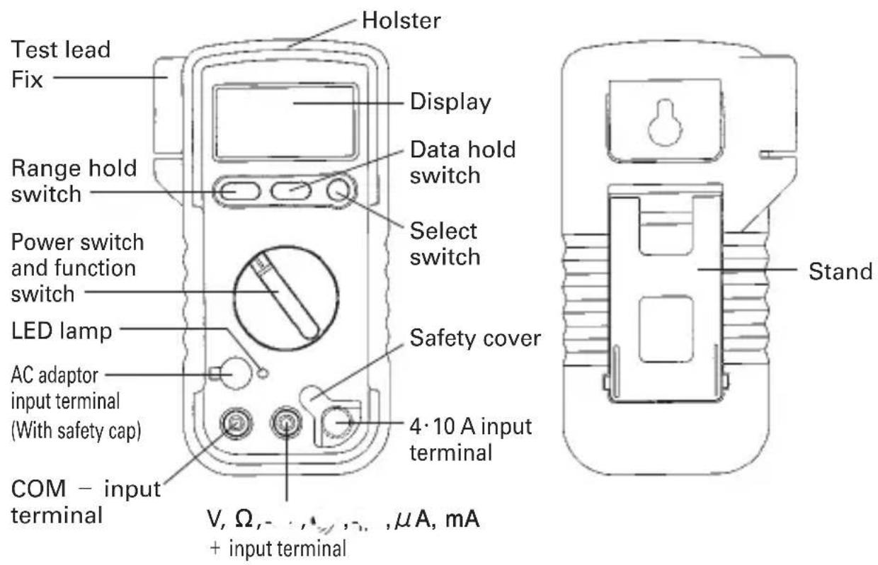
3-2 Multimeter, Test leads
[Fig 2]
【4】 Description of Functions
4-1 Switch and description
○ Power switch and function switch
Turn this switch to turn on and off the power and to select the functions of V, /- , , A , mA, A.
○ Range hold switch
Pressing this switch once sets the manual mode and the range is fixed. ("AUTO" on the display disappears)
Once the manual mode is set, the range moves each time this switch is pressed. Checking the unit on the display and the place of the decimal point, select a desired range. To return to the auto mode, keep pressing this switch until "AUTO" on the display appears.
○ Data hold switch
When this switch is pressed, the data display at that time continues ("DH" lights on the display). When the measuring input changes, the display will not change.
When this switch is pressed again, the hold status is canceled you can return to the measuring status. ("DH" on the display disappears.)
○Select switch
When this switch is pressed ( ), the each modes change as follows.
| V= /~ | == → ~ => |
| Ω/ - /• | Ω → . . → ↗ → Ω |
| - | (See 5-6 Capacity Measurement) |
| 400 · 4000μA :/~ | == → ~ => |
| 40 · 400 mA :/~ | |
| 4 · 10 A :/~ |

WARNING
Do not change over the function switch with a voltage applied to the measuring terminals.
● The PC20 does not have the auto power-off function.
When measurement is finished, be sure to return the function switch to the OFF position.
4-2 Connection with the personal computer
WARNING
Maximum input voltage in the event that is connect with computer is DC 300 V, AC 220 V (AC voltage is regulated by rms value of sinusoidal wave. Peak max. 310 V)
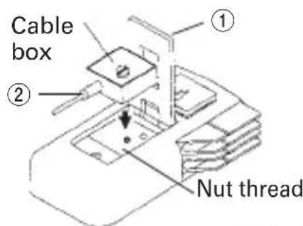
The multimeter is capable of DMM data communication using the RS232C / USB interface. When the multimeter on which the optional USB optical communication unit (KB-USB20) is mounted is connected to a PC, the multimeter will output data to the PC. It is required to purchase the optional PC link software (PC Link7) for this operation. For details, refer to the Help for the optional PC link software (PC Link7).
① The stand that is in the reverse side of a multimeter is opened.
② Attach the box part of cable to the multimeter.
③ The opposite side of cable is connected to the computer.
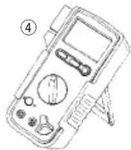
④ Please use and please set up the stand when use it.
natural_image
Line drawing of a digital multimeter with control panel and display (no text or symbols)[Fig 3]
● Data transfer speed to PC through KB-USB20 cable
| Function | Data transfer speed | Remarks | |
| except following functions Apporox. 0.5 s/times | |||
| 50 nF max. Apporox. 1.4 s/times | Data transfer speed is changed for each range when capacitance measurement. | ||
| ~ + | 500 nF Apporox. 1.7 s/times | ||
| ~ 5 μF | Apporox. 2 s/times | ||
| ~ 50 μF | Apporox. 5 s/times | ||
| ~ 100 μF | Apporox. 9 s/times | ||
| Ω, | Apporox. 0.7 s/times | ||
Note:
DMM stops Data transfer to PC while range is shifting.
4-3 Use of the AC adapter (AD-71AC-2)
WARNING
-
Maximum input voltage in the event that is connect with AC adapter is DC 300 V, AC 220 V (AC voltage is regulated by rms value of sinusoidal wave. Peak max. 310 V)
-
Do not use the AC adapter other than designated devices.
-
Do not use the AC adapter other than AC 100 V for the home.
① Pull up the safety cap from the AC adaptor input terminal of the multimeter.
② The plug of the AC adapter into the terminal of the multimeter.
③ The AC adapter into the outlet for the home (AC 100 V).
④ Turning the function switch of the multimeter and turn on the power supply.
![Outlet ③ AC adapter ① ② ③' ④ [Fig 4]](/content/2026/05/938556/images/aaaee7b52284c39c8d3e66ff127ce78b2ddd04450b03a89592807e4b4630391f.jpg)
●The incorporated battery and the AC adapter may be used together. Note, however, when the PC20 is used with the AC adapter only, the buzzer will not sound with such functions as the continuity check ( ^4 ).
●Insert the plug perpendicularly.
●Be sure to insert the plug to the position where the LED for confirmation of AC adapter connection illuminates.
5-1 Start-up Inspection

WARNING
- Never use meter if the meter or test leads are damaged or broken.
- Make sure that the test leads are not cut or otherwise damaged.
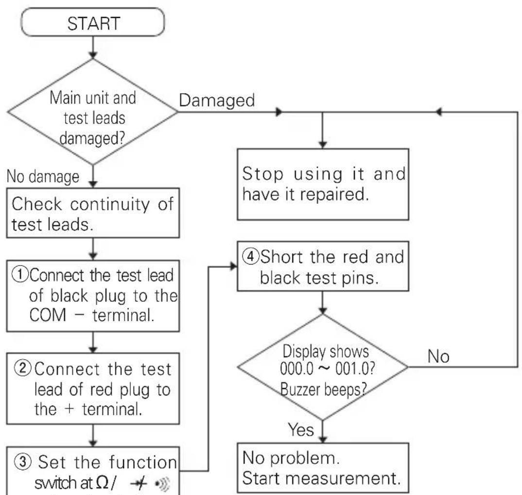
flowchart
graph TD
    A["START"] --> B{Main unit and test leads damaged?}
    B -->|No damage| C["Check continuity of test leads."]
    B -->|Damaged| D["Stop using it and have it repaired."]
    C --> E["①Connect the test lead of black plug to the COM - terminal."]
    E --> F["②Connect the test lead of red plug to the + terminal."]
    F --> G["③Set the function switch at Ω/ →"]
    G --> H{Display shows 000.0 ~ 001.0? Buzzer beeps?}
    H -->|No| I["Stop using it and have it repaired."]
    H -->|Yes| J["No problem. Start measurement."]
[Fig 5]
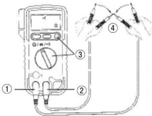
5-2 Voltage Measurement Maximum rating input value 1000 VDC or 750 VAC
WARNING
- Never apply an input signals exceeding the maximum rating input value.
- Be sure to disconnect the test pins from the circuit when changing the function.
- Always keep your fingers behind the finger guards on the probe when making measurements.
1) Applications
DCV : Measures batteries and DC circuits.
ACV : Measures sine-wave AC voltage as lighting voltages.
2) Measuring ranges
DCV : 400 mV \~ 1000 V (5 ranges)
ACV: 4 V \~ 750 V (4 ranges)
3) Measurement procedure (See Fig 6 or 7, page 10)
① Connect the black plug of the test lead to the COM - input terminal and the red plug to the + input terminal.
② Set the function switch at "V == / \~" function.
③ Select the select switch at "---" (DC) or "\~" (AC).
④ Apply the black test pin to the negative potential side of the circuit to measure and the red test pin to the positive potential side.
⑤ Read the value on the display.
⑥ After measurement, remove the red and black test pins from the circuit measured.
⑦ Turn the function switch to the position of OFF.
- In the AC 4 V range, a figure of about 3\~9 counts will stay on even if no input signal is present. But it is not malfunction.
- In the manual mode of the ACV function, the PC20 can be set to the 400 mV range and shows an approximate value. But its accuracy is not guaranteed.
- Since this instrument employs the means value system for its AC voltage measurement circuit, AC waveform other than sine wave may cause error.
5-3 Resistance Measurement ( )
WARNING
Never apply voltage to the input terminals.
1) Application
Resistance of resistors and circuits are measured.
2) Measuring ranges
400 Ω \~ 40 MΩ (6 ranges)
3) Measurement procedure (See Fig 8, page 11)
① Connect the black plug of the test lead to the COM - input terminal and the red plug to the + input terminal.
② Set the function switch at "Ω/→/•" function.
③ Select the select switch at "Ω" (MΩ).
④ Apply the black and red test pin to measured circuit.
⑤ Read the value on the display.
⑥ After measurement, remove the red and black test pins from the circuit measured.
⑦ Turn the function switch to the position of OFF.
- If measurement is likely to be influenced by noise, shield the object to measure with negative potential (test lead black).
- If a test pin is touched by a finger during measurement, measurement will be influenced by the resistance in the human body to result in measurement error.
● The input terminals release voltage is about 0.4 V.
● The reading may vary because of external inductance when measuring high resistance value.
5-4 Testing Diode ( )
WARNING
Never apply voltage to the input terminals.
1) Application
The quality of diodes is tested.
2) Measurement procedure (See Fig 9, page 12)
① Connect the black plug of the test lead to the COM - input terminal and the red plug to the + input terminal.
② Set the function switch at //· " function.
③ Select the select switch at "→".
④ Apply the black test pin to the cathode of the diode and the red test pin to the anode.
⑤ Make sure that the display shows a diode forward voltage drop.
⑥ Replace the red and black test pins, make sure that the display is the same as that when the test leads are released.
⑦ After measurement, release the red and black test pins from the object measured.
⑧ Turn the function switch to the position of OFF.
Judgement
When the items ⑤ and ⑥ are normal, the diode is good.
● The input terminals release voltage is about 1.5 V.
- If the diode forward voltage exceeds the release voltage, O.L is displayed even in a test in the forward direction.
5-5 Checking Continuity (●)

WARNING
Never apply voltage to the input terminals.
1) Application
Checking the continuity of wiring and selecting wires.
2) Measurement procedure (See Fig 10, page 13)
① Connect the black plug of the test lead to the COM - input terminal and the red plug to the + input terminal.
② Set the function switch at "Ω/→/•" function.
③ Select the select switch at "●●" .
④ Apply the red and black test pins to a circuit or conductor to measure.
⑤ The continuity can be judged by whether the buzzer sounds or not.
⑥ After measurement, release the red and black test pins from the object measured.
⑦ Turn the function switch to the position of OFF.
● The buzzer sounds when the resistance in a circuit to measure is less than 10 120 .
● Even if the buzzer does not sound, a resistance value up to 10 \~ 120 Ω will be displayed.
● The input terminals release voltage is about 0.4 V.
● The buzzer will not sound if the incorporated battery is removed from the PC20 and it is operated with the power supply of the AC adapter only.
- When a resistance value is in a range of 10 120 , noise will be mixed in the buzzer sound. But it is not malfunction.
5-6 Capacity Measurement (HV)
WARNING
- Never apply voltage to the input terminals.
- Be sure to discharge the capacitor prior to measurement.
1) Application
Measures capacitance of capacity.
2) Measuring ranges
50 nF* \~ 100 μ F (5 ranges) * 1000 nF = 1 μ F
3) Measurement procedure (See Fig 11, page 14)
① Connect the black plug of the test lead to the COM - input terminal and the red test lead to the + input terminal.
② Set the function switch at -1" function.
③ Press the SELECT switch to make the display show 00.00 nF. (The "REL" mark illuminates in the upper right area of the display.)
[CAUTION] If the SELECT switch is pressed immediately after the function switch has been set at "-H", the display may be locked, making measurement impossible. Should this be the case, set the function switch to a different range once, then back to "-H" and wait for more than 2 seconds before pressing the SELECT switch again.
④ Apply the red and black test pins to capacitor.
⑤ Read the value on the display.
⑥ After measurement, release the red and black test pins from the object measured.
⑦ Turn the function switch to the position of OFF.
● The "-H" function can be set to the auto range, but not to the manual range.
- In 5 nF and 50 nF ranges, large value is left, especially when disconnecting measuring terminals. This is not malfunction.
- For measurement of 100 nF (0.1 F) or below, the display will not stabilize due to the influence of ambient noise and floating capacity. It is therefore recommended that an object to measure (capacitor) be directly connected between the (+) and (-) measuring terminals of the PC20.
● As the capacitance increases, the measuring time becomes longer. Example: 2 to 4 seconds at 10 F 5 to 8 seconds at 50 F 13 to 16 seconds at 100 F
5-7 Current Measurement (μA, mA, A)
WARNING
- Never apply voltage to the input terminals.
- Be sure to make a series connection via load. (please see to above drawing)
- Do not apply an input exceeding the maximum rated current to the input terminals.
![Power Power Load Load [×] Wrong connection Right connection [○] Fig 6](/content/2026/05/938556/images/b0f2e755353391f83b116a5ec792391874d054acc0d0e3d98edf6c5b46d91c95.jpg)
5-7-1 Current Measurement ( A, mA)
Maximum rating input value DC/AC 4000 μA · 400 mA
1) Applications
Current in DC and AC circuit is measured.
2) Measuring ranges
DCA:400·4000 μA, 40·400 mA (4 ranges)
ACA:400·4000 μA, 40·400 mA (4 ranges)
3) Measurement procedure (See Fig 13, page 16)
① Connect the black plug of the test lead to the COM - input terminal and the red plug to the + input terminal.
② Set the function switch at "400·4000 μA" or "40·400 mA" function.
③ Select the select switch at "==" (DC) or "\~" (AC).
④ Apply the black test pin to the negative potential side of the circuit to measure and the red test pin to the positive potential side.
⑤ Read the value on the display.
⑥ After measurement, remove the red and black test pins from the circuit measured.
⑦ Turn the function switch to the position of OFF.
- If the display will not change when an input signal is applied (measurement is not possible), a probable cause is a blown fuse.
- Since this instrument employs the means value system for its AC voltage measurement circuit, AC waveform other than sine wave may cause error.
5-7-2 Current Measurement (A) Maximum rating input value DC/AC 10 A
WARNING
- Never apply voltage to the input terminals.
- Finish measurement within 45 seconds to prevent heat generation.
- Provide intervals 2 minutes or longer between measurements to prevent heat generation. (Continuous measurement:max 5 A)
- Perform measurement with the leads kept straight to prevent overheat.
1) Applications
Current in DC and AC circuit is measured.
2) Measuring ranges
DCA: 4·10 A (2 ranges), ACA: 4·10 A (2 ranges)
3) Measurement procedure (See Fig 14, page 17)
① Slide the safety cover of the PC20 to the left and insert the red plug of the test leads to the 4·10 A measuring terminal and the black plug to the COM (−) terminal.
② Set the function switch at "4·10 A == / \~" function.
③ Select the select switch at "==" (DC) or "\~" (AC).
④ Apply the black test pin to the negative potential side of the circuit to measure and the red test pin to the positive potential side.
⑤ Read the value on the display.
⑥ After measurement, remove the red and black test pins from the circuit measured.
⑦ Turn the function switch to the position of OFF.
- If the display will not change when an input signal is applied (measurement is not possible), a probable cause is a blown fuse.
- Since this instrument employs the means value system for its AC voltage measurement circuit, AC waveform other than sine wave may cause error.
5-8 How to use optional products

WARNING
Never apply an input signals exceeding the maximum rating input value of optional products.
5-8-1 Measurement using the AC flexible clamp sensor (CL3000) Maximum measurable current: AC 3000 A
1) Measurement target
AC sine wave of 50-60 Hz, such as the current consumption of a home appliance or power supply equipment.
2) Measurement ranges
Three ranges of AC 30 A, AC 300 A and AC 3000 A.
3) Measurement procedure
① Connect the red plug of the current probe to the + measurement terminal and the black plug to the COM (−) terminal.
② Set the function switch of this instrument (PC20) to "ACV".
③ Set the range hold button to the 6 V range.
④ Set the range setting knob of the current probe to the 30 A, 300 A or 3000 A range.
⑤ Clamp the measurement target conductor with the current probe.
⑥ If the range of the current probe is 30 A, read the displayed value
by multiplying it by 10. Similarly, multiply it by 100 with the 300 A range and multiply by 1000 with the 3000 A. The unit of the obtained value is A (ampere).
⑦ After the measurement, disconnect the current probe from the measurement target conductor.
⑧ Set the power switches of this instrument (PC20) and probe (CL3000) to OFF.
![⑥ ② ⑧ ACV OFF ① ③ ⑤ ④ [Fig 7]](/content/2026/05/938556/images/7a82f4666da6f56feb553bdc6b677fb7760ea8d9e9d051133d34363ff5796ae7.jpg)
5-8-2 DC·AC Clamp Probe (CL-22AD) Maximum measurement value DC/AC 200 A
① Connect the black plug of the current probe to the COM - terminal and the red plug to the + terminal.
② Set the function switch at "V==/\~" function.
③ Select the select switch at "==" (DC) or "\~" (AC).
④ Set the 400 mV range (at DC measurement) or 4 V range (at AC measurement) with range hold switch.
⑤ Select either 20 A or 200 A with selector knob of clamp probe. probe to make the display of the PC20 show "000.0".
⑥ Open the clamp part, have electric wire (one line) clamped.
⑦ Read the value on the display as follows.
DC 20 A : multiplying by 0.1 AC 20 A : multiplying by 100
DC 200 A: multiplying by 1 AC 200 A: multiplying by 1000
⑧ After measurement, open the clamp part and release clamp probe from the electric wire.
⑨ Turn the function switch of multimeter and selector knob of clamp probe to the position of OFF.
5-8-3 DC Clamp Probe (CL33DC) Maximum measurement value DC 300 A
① Connect the black plug of the current probe to the COM - input terminal and the red plug to the + input terminal.
② Set the function switch at "V == / \~" function.
③ Select the select switch at "==" (DC) and set the 400 mV range with the range hold switch.
④ Select either 30 A or 300 A with selector knob of clamp probe.
⑥ Read the value on the display in A unit and when current probe of the 30 A range after multiplying indicated value by 0.1, and the 300 A range after multiplying indicated value by 1.
⑦ After measurement, open the clamp part and release clamp probe from the electric wire.
⑧ Turn the function switch of multimeter and selector knob of clamp probe to the position of OFF.
5-8-4 Temperature probe (T-300PC) Measurement range 300 °C from -50 °C
① Connect the black plug to COM - input terminal and the red plug to + input terminal.
② Set the function switch at "Ω/→/·" function.
③ Select the select switch at "Ω" and set the 4 kΩ range with the range hold switch.
④ Apply the sensor to an object to measure.
⑤ Read the value on the display.
(When measuring temperature, please neglect the value of kΩ indicated on LCD of multimeter. The exact value of measured teperature is shown only on the window of PCLink.)
⑥ After measurement, release the sensor from the object measured.
⑦ Turn the function switch to the position of OFF.
【6】 MAINTENANCE

WARNING
- This section is very important for safety. Read and understand the following instruction fully and maintain your instrument properly.
- The instrument must be calibrated and inspected at least once a year to maintain the safety and accuracy.
6-1 Maintenance and inspection
- Appearance
• Is the appearance not damaged by falling?
- Test leads
• Is the cord of the test leads not damaged?
- Is the core wire not exposed at any place of the test leads?
If your instrument falls in any of the above items, do not use it and have it repaired or replace it with a new one.
● Make sure that the test leads are not cut, referring to the section.
6-2 Calibration
The calibration and inspection may be conducted by the dealer.
For more information, please contact the dealer.
6-3 How to Replace Battery and Fuse (See Fig 19, page 23)
WARNING
-
If the rear case is removed with input applied to the input terminals, you may get electrical shock. Before starting the work, always make ure that no inputs is applied.
-
Be sure to use the fuse is same rating so as to ensure safety and performance of tester.
-
When operator remove the rear case, do not touch the internal parts or wire with hand.
① Remove the holster.
② Remove the rear case screw with a screwdriver.
③ Remove the rear case.
④ Take out the battery and replace it with a new one.
⑤ Attach the rear case and fix it with the the screw.
⑥ Attach the holster.
* Do not use mix new and old batteries together.
Fuse of the Specified Rating and Type
(Fuse with arc-extinguishing agent)
0.5 A/250 V 5×20 mm Blowout capacity:1500 A
12.5 A/250 V 6.3×32 mm Blowout capacity:125 A
① Remove the holster.
② Remove the rear case screw with a screwdriver.
③ Remove the rear case.
④ Pull out the fuse out of holder on the circuit board and replace it.
⑤ Put back rear case where it was and tighten the screw.
⑥ Check and see whether or not indications of respective ranges are normal.
⑦ Attach the holster.
6-4 Cleaning and Storage
CAUTION
- The panel and the case are not resistant to volatile solvent and must not be cleaned with thinner or alcohol.
For cleaning, use dry, soft cloth and wipe it lightly. - The panel and the case are not resistant to heat. Do not place the instrument near heat-generating devices (such as a soldering iron).
- Do not store the instrument in a place where it may be subjected to vibration or from where it may fall.
- For storing the instrument, avoid hot, cold or humid places or places under direct sunlight or where condensation is anticipated.
Following the above instructions, store the instrument in good environment.
【7】 SPECIFICATIONS
7-1 Measurement Range and Accuracy
Accuracy assurance range : 23 ± 5 °C 80 %RH MAX. No condensation.
| Function | Range | Input Resistance | Accuracy Remarks | |
| DCV | 400.0 mV ≧ 100 M Ω | ±(0.5 %rdg+2 dgt) | ||
| 4.000 V | Approx. 11 MΩ | ±(0.9 %rdg+2 dgt) | ||
| 40.00 V | Approx. 10 MΩ | |||
| 400.0 V | ||||
| 1000 V | ±(1.0 %rdg+2 dgt) | |||
| ACV | 4.000 V | Approx. 11 MΩ | ±(1.2 %rdg+9 dgt) | Accuracy in the case of sin wave40 ~ 500 Hz |
| 40.00 V | Approx. 10 MΩ | ±(1.2 %rdg+5 dgt) | ||
| 400.0 V | ||||
| 750 V | ±(1.5 %rdg+5 dgt) | |||
| DCA | 400.0 μA, | Approx. 100Ω | ±(1.5 %rdg+2 dgt) | 10 A range :Continuous measurement :max 5 A |
| 4000 μA | ||||
| 40.00 mA, | Approx. 1Ω | |||
| 400.0 mA | ||||
| 4.000 A, | Approx. 0.01Ω | ±(2.0 %rdg+2 dgt) | ||
| 10.00 A | ||||
| ACA | 400.0 μA, | Approx. 100Ω | ±(1.8 %rdg+5 dgt) | Accuracy in the case of sin wave40 ~ 500 Hz10 A range :Continuous measurement :max 5 A |
| 4000 μA | ||||
| 40.00 mA, | Approx. 1Ω | |||
| 400.0 mA | ||||
| 4.000 A, | Approx. 0.01Ω | ±(2.5 %rdg+5 dgt) | ||
| 10.00 A | ||||
| Ω | 400.0 Ω | ±(1.5 %rdg+5 dgt) | Open voltage Apporox. 0.4 V | |
| 4.000 k Ω | ±(1.2 %rdg+4 dgt) | |||
| 40.00 k Ω | ||||
| 400.0 k Ω | ||||
| 4.000 M Ω | ±(1.8 %rdg+2 dgt) | |||
| 40.00 M Ω | ±(3.0 %rdg+2 dgt) | |||
| ◆ | Open voltage ApproxBuzzer sound at approx. 10 ~ 12Ω max. | |||
| → | Open voltage Approx 1.5 V | |||
| → | 50.00 nF | ±(5.0 %rdg+6 dgt) | Auto range only | |
| 500.0 nF | ||||
| 5.000 μF | ||||
| 50.00 μF | ||||
| 100.0 μF | ||||
| Temp°C | - 50 ~ 300 | ±15 %rdg±4.8°C | Option | |
If there is presence of strong magnetic field generated by conductor fed large current, motors or strong radio wave, a measurement may not be accurate.
Specifications and external appearance of the product described above may be revised for modification without prior notice.
7-2 General Specifications
Measuring Method : △ Σ method
Display : 4000 counts
Range selection : Auto and manual ranges
Over display : "O.L" is displayed
(except DC/AC 10 A, DC 1000 V, AC 750 V ranges)
Polarity : Automatic selection (only " - " is displayed)
Battery discharge display
: If the internal battery has been consumed and the voltage drops, the display shows.
Sampling rate : Approx. 3 times/sec.
Accuracy assurance temperature /humidity range
: 23 ± 5 °C 80 %RH max. No condensation.
Operating temperature /humidity range
: 0 \~ 40 °C 80 %RH max. No condensation.
Storage temperature /humidity range
:-10 \~ 50 °C 70 %RH max. No condensation.
Environmental condition
: Operating altitude <2000 m, pollution degree Ⅱ
Power supply : R6 (IEC) dry battery, 2 pieces
Power consumption : Approx. 7 mW TPY. (at DCV)
Battery life : Approx. 150 hours at DCV
Fuse protection : 0.5 A/250 V Fast acting fuse ( 5×20 mm)
Blowout capacity, 1500 A Fuse with arc-extinguishing agent 12.5 A/250 V Fast acting fuse ( 6.3×32 mm) Blowout capacity, 125 A
Dimension and Mass: 167(H) × 90(W) × 48(D)mm
Approx. 330 g (holster attached.)
Accessories : Instruction manual, Test leads (TL-21a), Holster (H-70)
7-3 Optional accessories
- Current probe : CL3000, CL-22AD, CL33DC
• Temperature probe : T-300PC - Soft case : C-SP
- AC Adaptor : AD-71AC-2 (Input AC 100 V)
• USB optical communication unit : KB-USB20 - PC link software : PC Link7
- Alligator clip : CL-14
[8] After-Sales Service
8-1 Warranty and Provision
Sanwa offers comprehensive warranty services to its end-users and to its product resellers. Under Sanwa's general warranty policy, each instrument is warranted to be free from defects in workmanship or material under normal use for the period of one (1) year from the date of purchase.
This warranty policy is valid within the country of purchase only, and applied only to the product purchased from Sanwa authorized agent or distributor.
Sanwa reserves the right to inspect all warranty claims to determine the extent to which the warranty policy shall apply. This warranty shall not apply to fuses, disposables batteries, or any product or parts, which have been subject to one of the following causes:
- A failure due to improper handling or use that deviates from the instruction manual.
- A failure due to inadequate repair or modification by people other than Sanwa service personnel.
- A failure due to causes not attributable to this product such as fire, flood and other natural disaster.
- Non-operation due to a discharged battery.
- A failure or damage due to transportation, relocation or dropping after the purchase.
8-2 Repair
Customers are asked to provide the following information when requesting services:
- Customer name, address, and contact information
- Description of problem
- Description of product configuration
- Model Number
- Product Serial Number
- Proof of Date-of-Purchase
- Where you purchased the product
1) Prior to requesting repair, please check the following:
Capacity of the built-in battery, polarity of installation and discontinuity of the test leads.
2) Repair during the warranty period:
The failed meter will be repaired in accordance with the conditions stipulated in 8-1 Warranty and Provision.
3) Repair after the warranty period has expired:
In some cases, repair and transportation cost may become higher than the price of the product. Please contact Sanwa authorized agent / service provider in advance.
The minimum retention period of service functional parts is 6 years after the discontinuation of manufacture. This retention period is the repair warranty period. Please note, however, if such functional parts become unavailable for reasons of discontinuation of manufacture, etc., the retention period may become shorter accordingly.
4) Precautions when sending the product to be repaired:
To ensure the safety of the product during transportation, place the product in a box that is larger than the product 5 times or more in volume and fill cushion materials fully and then clearly mark “Repair Product Enclosed” on the box surface. The cost of sending and returning the product shall be borne by the customer.
8-3 SANWA web site
http://www.sanwa-meter.co.jp
E-mail: exp_sales@sanwa-meter.co.jp
sanwa®
三和電気計器株式会社
Dempa Bldg., 4-4 Sotokanda 2-Chome, Chiyoda-ku, Tokyo, Japan
- 【1】 SAFETY PRECAUTIONS: Before use, read the following safety precautions
- 【4】 Description of Functions
- 【6】 MAINTENANCE
- 【7】 SPECIFICATIONS
- 【1】 SAFETY PRECAUTIONS : Before use, read the following safety precautions
- 1-1 Explanation of Warning Symbols
- 1-2 Warning Instruction for safe use
- WARNING
- CAUTION
- 1-3 Maximum Overload Protection Input
- [2] APPLICATION AND FEATURES
- 2-1 Application
- 2-2 Features
- 3-2 Multimeter, Test leads
- 4-1 Switch and description
- ○ Power switch and function switch
- ○ Range hold switch
- ○ Data hold switch
- ○Select switch
- ● The PC20 does not have the auto power-off function.
- 4-2 Connection with the personal computer
- Note:
- 4-3 Use of the AC adapter (AD-71AC-2)
- 5-1 Start-up Inspection
- 5-2 Voltage Measurement Maximum rating input value 1000 VDC or 750 VAC
- 1) Applications
- 2) Measuring ranges
- 3) Measurement procedure (See Fig 6 or 7, page 10)
- 5-3 Resistance Measurement ( )
- 5-4 Testing Diode ( → )
- Judgement
- 5-5 Checking Continuity (●)
- 5-6 Capacity Measurement (HV)
- 5-7 Current Measurement (μA, mA, A)
- 5-7-1 Current Measurement ( A, mA)
- 5-7-2 Current Measurement (A) Maximum rating input value DC/AC 10 A
- 5-8 How to use optional products
- 5-8-1 Measurement using the AC flexible clamp sensor (CL3000) Maximum measurable current: AC 3000 A
- 6-1 Maintenance and inspection
- 6-2 Calibration
- 6-3 How to Replace Battery and Fuse (See Fig 19, page 23)
- Fuse of the Specified Rating and Type
- 6-4 Cleaning and Storage
- 7-1 Measurement Range and Accuracy
- 7-2 General Specifications
- 7-3 Optional accessories
- [8] After-Sales Service
- 8-1 Warranty and Provision
- 8-2 Repair
- 8-3 SANWA web site
- sanwa®
- 三和電気計器株式会社
Brand : Sanwa
Model : PC20
Category : Multimeter