DTX4200XP - Walkie-talkie Oricom - Free user manual and instructions
Find the device manual for free DTX4200XP Oricom in PDF.


| Product Type | UHF CB Radio (Citizen Band) |
| Brand | Oricom |
| Model | DTX4200XP |
| Channels | 80 UHF CB channels (channels 1–80, including repeater channels) |
| Frequency Band | 477 MHz (UHF CB) |
| RF Power Output | 5 Watts (maximum) |
| Dimensions (approx.) | 160 mm (W) x 50 mm (H) x 120 mm (D) (typical for mountable radio) |
| Weight (approx.) | 1.2 kg (including mounting bracket) |
| Power Supply | 12V DC (negative ground) via vehicle battery, 3 Amp fuse |
| Dust/Water Resistance | IP54 (dust and splash resistant) |
| Display | 96-color multi-color backlight LCD, 5-level brightness plus auto |
| Dual Receive | Simultaneous monitoring of main and sub channel (SRX) |
| Scan Modes | Open scan, Group memory scan, Group tone scan |
| Privacy Codes | 38 CTCSS tones and 104 DCS codes |
| Duplex (Repeater) Operation | Yes, on channels 1–8 and 41–48 (with offset to 31–38 and 71–78) |
| Memory Groups | 3 groups (A, B, C) with 16 channels each (total 48 memory channels) |
| External Speaker Jack | 3.5 mm for optional external speaker (SPE85) |
| Microphone | Controller speaker microphone with Jog Wheel control |
| TPI (Transmit Power Indicator) | Real-time VSWR and power level display |
| Safety Features | Auto power off (off/1h/2h/4h), busy channel lock, squelch tail mute |
| Warranty | 5 years (Australia Express Warranty) |
| Accessories Included | Mounting bracket, microphone hanger, DC power cable |
| Optional Accessories | External speaker (SPE85), magnetic microphone holder (MMM100) |
| Country of Origin | Korea |
Frequently Asked Questions - DTX4200XP Oricom
User questions about DTX4200XP Oricom
0 question about this device. Answer the ones you know or ask your own.
Ask a new question about this device
Download the instructions for your Walkie-talkie in PDF format for free! Find your manual DTX4200XP - Oricom and take your electronic device back in hand. On this page are published all the documents necessary for the use of your device. DTX4200XP by Oricom.
USER MANUAL DTX4200XP Oricom
Operating Instructions
DTX4200XP 80 Channel UHF Citizen Band Radio
Keep this user guide for future reference. Always retain your proof of purchase in case of
Warranty service.
www.oricom.com.au
When a narrowband radio receives a transmission from an older wideband radio the speech may sound loud and distorted – simply adjust your radio volume for the best listening performance. When an older wideband radio receives a signal from a new narrowband radio the speech may sound quieter - simply adjust your radio volume for best listening performance. When operating a narrowband radio or Channel 41 - 80 interference is possible from wideband radios transmitting on high power or on adjacent frequency.
The issues described above are not a fault of the radio but a consequence of mixed use of wideband and narrowband radios.

R-NZ
This unit complies with all relevant Australian and New Zealand approval requirements AS/NZS 4365:2011

Introduction 4
Important information ....5
Installation of your Oricom Radio....6
Controls and Indicators 8
Operations....12
UHF CB channels and frequencies 27
Express Warranty (Australia) 31
Need Help?
If you need assistance setting up or using your Oricom product now or in the future, call Oricom Support.
Australia (02) 4574 8888
www.oricom.com.au
Mon-Fri 8am – 6pm AEST
New Zealand 0800 67 42 66
www.oricom.co.nz
Mon-Fri 10am – 8pm NZST
Introduction
Thank you for choosing the Oricom DTX4200XP 5 watt UHF CB Radio.
Oricom is a 100% Australian owned and operated company, engineering radio communication products specifically for the diverse and unique conditions of Australia and New Zealand since 2003. This product was manufactured in Korea under strict quality control.
Key Features
- Dual receive
• IP54 dust and splash resistant
• 3 memory groups of 16 channels per group
• 96 Multi-colour backlight display - Backlight brightness (5 pre-set levels plus auto)
- Fast scanning 80 channels within 3 seconds
- Rotary volume/channel and squelch control
- Duplex
• 38 CTCSS & 104 DCS codes
• Heavy duty diecast metal chassis - Slide-in mounting bracket
• Auto power off (off/1h/2h/4h) - 3.5mm external jack (for optional external speaker (Model No. SPE85))
Optional Accessories (See page 7 for details)
External speaker (SPE85)
Magnetic microphone holder (MMM100)
Please read before installing or operating your Oricom Radio
The operation of your UHF radio in Australia and New Zealand is subject to conditions in the following licenses:
In Australia the ACMA Radio communications (Citizen Band Radio Stations) and in New Zealand by MED the General User Radio License for Citizen Band Radio.
Safety Information and Warnings

Potentially Explosive Atmospheres
Turn your radio OFF when in any area with a potentially explosive atmosphere. Sparks in such areas could cause an explosion or fire resulting in injury or even death.
NOTE: Areas with potentially explosive atmospheres are often, but not always clearly marked. They include fuelling areas such as below deck on boats; fuel or chemical transfer or storage facilities; areas where the air contains chemicals or particles, such as grain, dust, or metal powders; and any other area where you would normally be advised to turn off your vehicle engine.
Blasting Caps and Areas
To avoid possible interference with blasting operations, turn your radio OFF near electrical blasting caps or in a “blasting area” or in areas posted: “Turn off two way radios.” Obey all signs and instructions.
Electromagnetic Interference/Compatibility
Nearly every electronic device is susceptible to electromagnetic interference (EMI). To avoid the possibility of electromagnetic interference and/or compatibility conflicts, turn off your radio in any location where posted notices instruct you to do so such as health care facilities.
CAUTION
When installing your radio in your vehicle, check that during installation you do not damage any wiring or vehicle components that may be hidden around the mounting position. Ensure the installation does not interfere with the operation of the vehicle and meets all regulatory and safety requirements for accessories fitted to your vehicle.
For optimum performance your radio needs to be installed correctly. If you are unsure about how to install your radio, we suggest you have your radio professionally installed by a UHF specialist or Auto electrician. When installing the radio, avoid mounting it close to heaters or air conditioners. Never press the PTT or CALL button before connecting the antenna to the radio.
Wiring Methods
There are two possible wiring configurations for connecting to the vehicles power supply.
A. Radio stays ON when the ignition is switched OFF
Connect the radio's negative (black) lead to the vehicle chassis, or directly to the battery's negative terminal.
Connect the radio's positive (red) lead via the 3 Amp fuse to the battery's positive terminal. Alternatively, the positive lead could be connected at the fuse box at a point that has DC Power continuously available (preferably the battery side of the ignition switch) via the 3 Amp fuse.
B. Radio turns OFF with the ignition switch
Connect the radio's negative (black) lead to the vehicle's chassis, or directly to the battery's negative terminal.
The radio's positive (red) lead should connect to an accessory point in the vehicle's fuse box via the 3 Amp fuse.
Antenna information
The antenna (not supplied) is of critical importance, to maximize your output power and receiver sensitivity.
A poorly installed, inferior quality antenna or one not designed for the correct frequency band will give poor performance. You should only purchase an antenna designed for the 477MHz frequency band.
Antenna installation
- Connect the antenna to the rear antenna socket using a PL259 coaxial connector (not supplied).
- To obtain maximum performance from the radio, select a high quality antenna and mount it in a good location. Never press the PTT or CALL button before connecting the antenna to the radio.
- For best performance always mount your antenna as high as possible and away from all other antennas or poles.
Optional Accessories
The following Oricom accessories can be purchased directly from Oricom. Visit oricom.com.au.
Optional Magnetic Microphone Holder
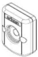
Mounting bracket for easy installation. Model number MMM100.
Optional External Speaker
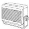
Depending on the installation, it may be necessary to use an external speaker (not supplied) to give improved volume and clarity. This can be plugged into the EXT-SPK socket on the rear of the unit. Model No. SPE85.
Controls and Indicators
Front View
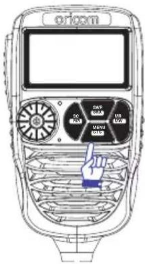
Oricom offer a unique Jog Wheel, which makes using the Controller Speaker Microphone simple and intuitive.
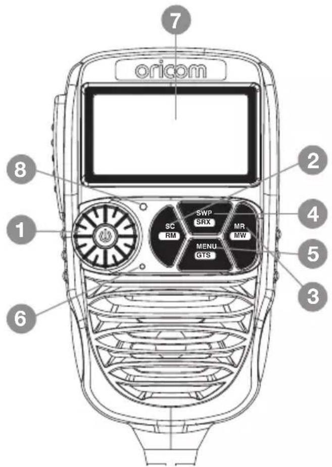
- (Jog Wheel) Power on/off and Volume/channel/squelch and SVL (sub receiver volume)
- Scan (open scan/memory group scan)/scan skip
- Memory recall/memory write
- Main & Sub channel swapping/SRX on/off
- Menu/Group tone scan
- Microphone
- LCD display
- Light sensor
Rear View
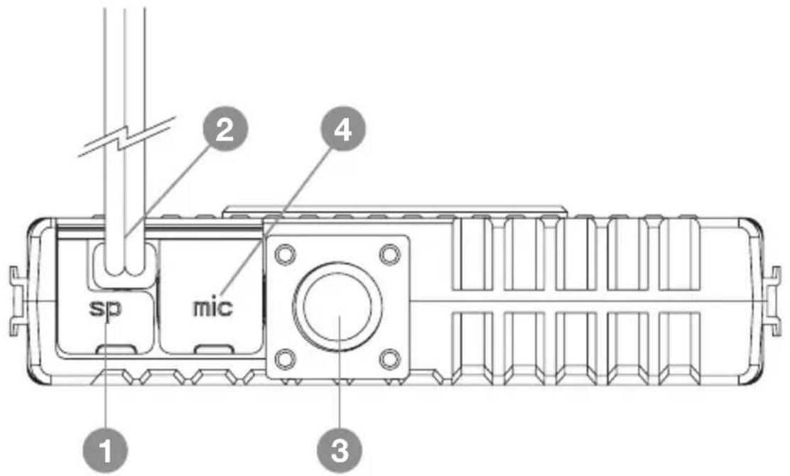
- 3.5mm external jack for optional 8 ohm speaker
- Power supply connection
- Antenna connection
- Microphone Jack
LCD Icons & Indicators
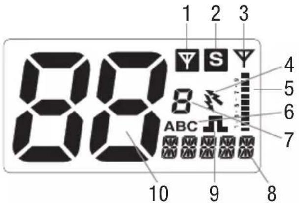
- Sub channel busy 6. Group display (A, B, C groups)
- Sub channel on 7. Group address channel
- Main receiver busy 8. Status display
- Duplex on 9. CTCSS or DCS on
- Signal strength & TX power & SWR meter 10. Channel display
Installation of the DTX4200XP and fitting optional accessories
Mounting the UHF radio
The universal mounting bracket supplied with your UHF radio allows overhead/dash mounting.
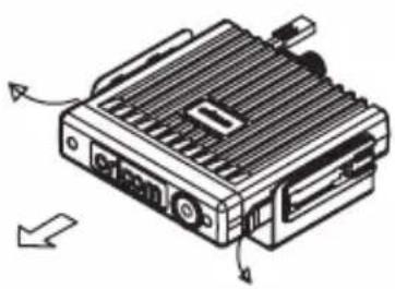
Mount the UHF radio via the bracket, securely with the supplied screws in the desired location, ensuring the surface is sturdy and can support the weight of the radio.
TO MOUNT: SLIDE
INTO UNIVERSAL
MOUNTING BRACKET
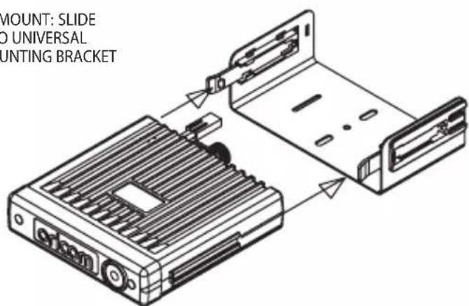
TO REMOVE: SLIDE OUT HOLDING BRACKETS AWAY FROM UHF RADIO
natural_image
Technical line drawing of a mechanical device with ports and mounting holes (no text or symbols)Installation Diagram
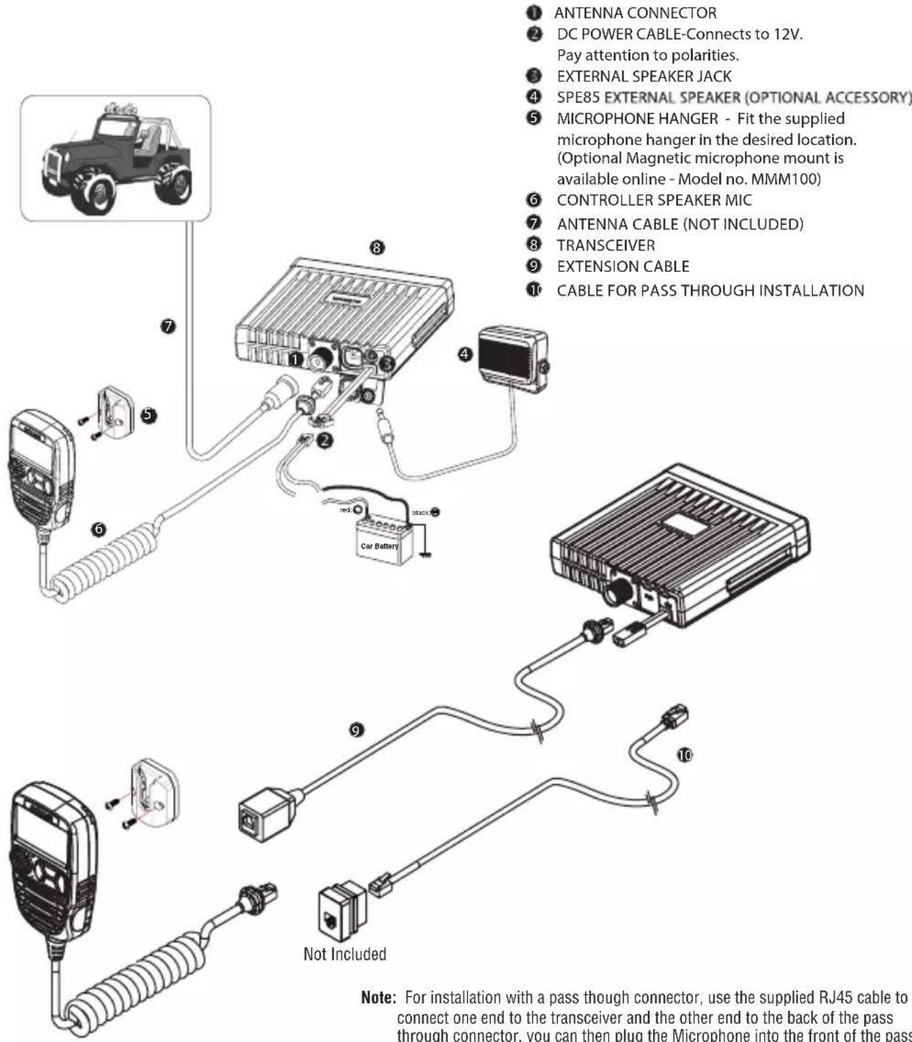
Note: For installation with a pass though connector, use the supplied RJ45 cable to connect one end to the transceiver and the other end to the back of the pass through connector, you can then plug the Microphone into the front of the pass through connector.
Operations
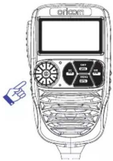
Turning on the Power
Press and hold the Jog Wheel.
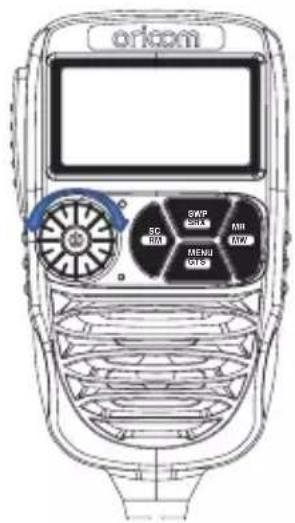
Setting the Volume
Rotate the Jog Wheel clockwise to adjust the sound level for comfortable reception.
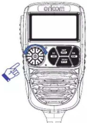
Selecting a channel
Press Jog Wheel once. "CH" will appear on the LCD.
Select the channel by rotating the Jog Wheel. Turn the Jog Wheel clockwise to adjust channel UP. Turn the Jog Wheel anti-clockwise to adjust channel DOWN.
Setting the Squelch Level
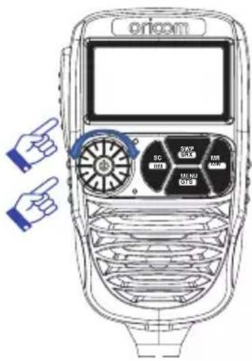
- Press Jog Wheel 2 times. The current squelch level is displayed.
- Select the squelch level by rotating the Jog Wheel.
1 - Max sensitivity (Min. squelch)
15 - Min. sensitivity (Max/Tight squelch)
Off - Squelch open
Setting SRX (Sub Receiver) Volume
- Press Jog Wheel 3 times, then "SVL" is displayed.
- Rotate the Jog Wheel to adjust the SRX volume.
Note :
* If a button is not pressed within 2 seconds the radio will automatically exit the sub display of "VOL" "CH" "SQL" and "SVL".
PTT (Push-To-Talk) button
Pressing the PTT button activates the transmitter.
The RF (radio frequency) level will appear on the LCD display as you are transmitting.
To receive, release the PTT button and then TX will disappear on the LCD display.
When transmitting, hold the Mic two inches (5cm) from your mouth and speak clearly in a normal voice across the front of the Mic area.
Scanning
The Scan feature allows you to search for active channels automatically.
There are 3 scanning modes:
Open Scan, Group Memory Scan and Group tone Scan (a special case of Group Memory Scan).
Open scan
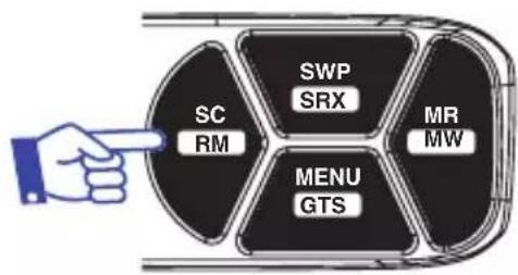
Press SC/RM to start scan. The OS-SC sub menu display will appear on the LCD display.
When a signal is found, scanning will stop at that channel to allow the signal to be heard, then resume scanning when the channel is clear again.
The scan resume time can be set to 5, 10 or 15 seconds of P5 (default).
ch 1-2-3-4-5-6-7 ..... 77-78-79-80
flowchart
graph TD
    A["Hand pointing"] --> B["SC RM"]
    A --> C["SWP SRX"]
    A --> D["MENU GTS"]
    A --> E["MR MW"]
Note: During open scan rotating the Jog Wheel will not change the scan direction.
To stop the scan, press the SC/RM button or press the PTT.
Remove Memory in Scanning
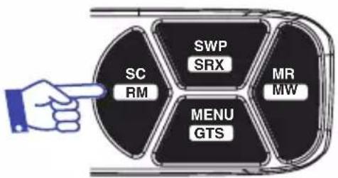
To remove a channel from the scan, press and hold SC/RM button for 2 seconds.
The channel will be removed from the current scan. When the scan stops, the removed channel will be reinstated.
flowchart
graph TD
    A["Hand Icon"] --> B["Central Node"]
    B --> C["SC RM"]
    B --> D["SWP SRX"]
    B --> E["MENU GTS"]
    B --> F["MR MW"]
For example we are removing CH02 from the scan. You may want to remove this channel due to constant noise.
- Press SC/RM button for 2 seconds.
- Scanning will resume.
- Channel 02 is removed from this scan.
Scan 1-2-3-4-5-6-7 ..... 77-78-79-80
RM Scan 1-3-4-5-6-7 ..... 77-78-79-80
Note: Up to 10 channels can be removed for the current scan.
Group Memory Scan
Memory scan must be stored to the memory channels in groups A to C.
Refer to memory recall function on page 16.
- Press MR/MW button to change between A, B, C (A,B,C will start flashing).
When A, B, C are flashing, all groups will be scanned starting with the selected group. When A, B and C are not flashing, then only the selected group will scan.
- Press Scan button to start group scan.
The MS-SC sub menu display appears on the LCD.
- To stop Group memory Scan, press SC/RM button or PTT.
Group Tone Scan
When Group Tone Scan is enabled, it will allow continual communication across congested channels.
Group tone scan channels stored into Group memory scan and only opens the squelch for signals with the correct subcode (38 CTCSS or 104 DCS tone).
To achieve this, all radios in your group must have the same channels in A, B, C memory (group memory channels) and use the same Subcode (38 CTCSS and 104 DCS tone).
By scanning only group channels, radios in the network will be able to detect and receive group transmissions which will be continual communication without interruption. When transmitting in this mode, the radio switches to an unused group channel if it detects another signal with no code/the wrong code, on the channel last used by the group.
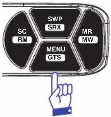
- Press and hold MENU/GTS button to activate Group Tone Scan.
All group tone scan stored into Group memory channel and CTCSS 01 (67Hz) is set for Group Tone Scan.
The group tone code can be changed in the settings menu.
- To stop Group memory Scan, Press MENU/GTS button or PTT.
flowchart
graph TD
    A["SC RM"] --> B["SWP SRX"]
    B --> C["MENU GTS"]
    C --> D["MR MW"]
    D --> E["Hand icon pointing to the center"]
Memory Recall
This feature allows the user to recall the stored channels using the MR button.
To access the stored channels, simply press the "MR" button, and the "A" will appear at the right side on the LCD. Press the MR button again to cycle through A - B - C (A,B,C will start flashing).
When A, B and C are flashing, press SC/RM button to start all memory group scanning.
For scanning A, B or C only, select non flashing preferred group (A, B or C) press SC/RM.
The DTX4200XP has no information stored in the memory channels.
Memory Write
Select the channel you want to store.
For this example we will write CH09 to B group and group channel 8.
- Press and hold the MR/MW button to store a channel.
"A" will appear and the group channel will flash. - Press MR/MW button to select B group.
- Press Jog Wheel to engage CH mode.
- Rotate Jog Wheel until 8 is shown in group channel display.
- Press and hold MR/MW button to save & exit from memory write.
SWP (Swapping Dual RX channel)
The DTX4200XP can receive two channels simultaneously.
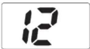
The main receiver default channel is 12 and Sub receiver default channel is 40.
The Sub channel can be turned on and off by pressing and holding the SWP/SRX button. The "S" indicator on the display will be on if the SRX is on.
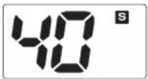
It is not possible to transmit on the SRX channel you must swap the SRX and Main RX to transmit on that channel.
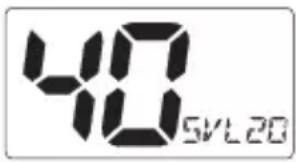
To adjust the volume of the SRX channel, push the channel change selector 3 times, the display will show SVL and the level. Adjust desired volume level by rotating channel change selector, the setting will automatically save, press PTT to exit.

SRX On/Off
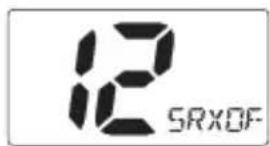
Press and hold SWP/SRX button to turn SWP/SRX off.
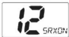
To return to Dual RX mode, press and hold the SRX button for 2 seconds.
Menu list
* Press MENU/GTS button to access menu.
* Use the Jog Wheel to change the value of each setting.
* If a button is not pressed within 8 seconds the radio will automatically exit the menu mode.
* You can exit the menu at any time by briefly pressing PTT button.
* Please see below menu modes.
| Function Step Display Default | |||
| Duplex On/Off | Off | 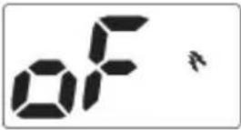 | On |
 |||
| CTCSS and DCS | Off | 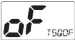 | Offto |
| 104 | |||
| Group Tone Scan | CT1(67Hz) | 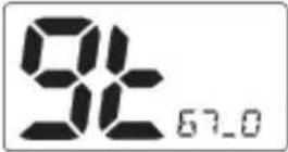 | CT1 (67Hz)to |
| DCS104 | |||
| Backlight LED colour | 0 | 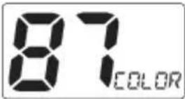 | 87(Sky Blue)to |
| 95 | |||
| Backlight Dimmer | Auto | 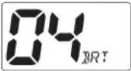 | 4 |
| to | |||
| 5 | |||
| Factory Reset | User | 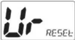 | User reset |
| Factory | |||
| Squelch tail | Off | 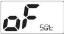 | Off |
| On | |||
| Busy channel lock | Off | 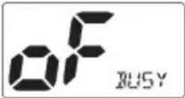 | Off |
| On | |||
| Key Beep | Off | 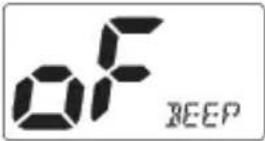 | Off |
| On | |||
| Logo Display | On | 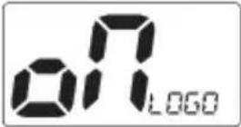 | On |
| Off | |||
| TPI | On | 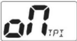 | On |
| Off | |||
| Scan resume time | P5 |  | P5to |
| 5,10,15 | |||
| Auto power Off | Off | 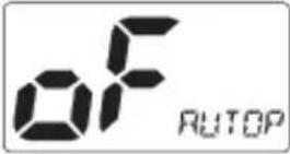 | Offto |
| 1H,2H,4H | |||
| Software version | ver--3 | ||
Duplex
General
Your radio has a Repeater Access function to allow use of local repeater stations (if available in your area). Repeaters are shared radio systems installed by interested parties (clubs, local business etc.) that receive transmissions on specific channels and re-transmit (or repeat) the received signal to another channel.
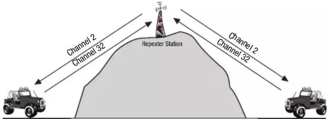
The Repeater Access function can be set (from channel 1 to 8 and 41 - 48) used by local repeater stations. When activated, your radio will receive the Repeater on its specific channel (all repeater outputs are on channel 1 to 8 and 41 to 48) but transmit to the repeater channel 31 through 38 and 71 to 78.
(Factory default is set to On for all repeater channels).
e.g.
CH01 on Duplex mode will receive on CH01 but transmit on CH31.
CH02 on Duplex mode will receive on CH02 but transmit on CH32.
If you transmit on CH01 duplex mode, you are actually transmitting on CH31.
The repeater station receives your signal on CH31 and retransmits on CH01.
Your UHF radio allows you to pre-select Duplex operation individually on each channel.
| CH and Number | Simplex mode Transmit/Receiver | Duplex mode Transmit/Receiver |
| Frequency (MHz) Frequency (MHz) | ||
| 1 476 | 425 477.175 CH31 | |
| 2 476 | 450 477.200 CH32 | |
| 3 476 | 475 477.225 CH33 | |
| 4 476 | 500 477.250 CH34 | |
| 5 476 | 525 477.275 CH35 | |
| 6 476 | 550 477.300 CH36 | |
| 7 476 | 575 477.325 CH37 | |
| 8 476 | 600 477.350 CH38 | |
| 41 476 | 4375 477.1875 CH71 | |
| 42 476 | 4625 477.2125 CH72 | |
| 43 476 | 4875 477.2375 CH73 | |
| 44 476 | 5125 477.2625 CH74 | |
| 45 467 | 5375 477.2875 CH75 | |
| 46 476 | 5625 477.3125 CH76 | |
| 47 476 | 5875 477.3375 CH77 | |
| 48 476 | 6125 477.3625 CH78 | |
For this example we are adopting CH01 as the channel being used for repeater use.
- Press Menu to display Duplex setting.
- Turn the Jog Wheel to change the setting between ON and OFF.
Note: You can only turn Duplex on when you are on a duplex channel. - Press PTT to save & exit from the menu mode.
- Duplex on icon is displayed when a selected channel is set to Duplex mode. See LCD Icons & Indicators on page 10 No.3.
CTCSS and DCS setting
This feature allows you to receive signals only from callers who have selected the same CTCSS and DCS code.
DCS is similar to CTCSS. It provides 104 extra, digitally coded, squelch codes that follow after the 38 CTCSS codes. CTCSS 1 - 38, followed by DCS 1 - 104. (Displays A0 to A4 for 100 to 104)
CTCSS and DCS are not available on CH05 and CH35. For your reference a list of the available channels, corresponding frequencies and guidelines for their use and selection is in the CTCSS and DCS channel list on pages 29 and 30.
For Australia, channel 05 and 35 are reserved for Emergency calls.
Group Tone setting
The group tone scan default tone selected is CTCSS 01 (67Hz).
You can select from CTCC 01 - 38 to DCS 01 to 104 code for Group tone scan.
96 Multi-colour Backlight
You can select from 96 different multi-colour backlighting for the LCD backlight.
Backlight dimmer
You can reduce the brightness of the backlight by selecting levels 1 to 5, off or Auto, which will adjust the level of brightness depending on ambient light.
Factory Reset
To reset your radio, press and hold SC/RM button while turning the power on.
The display "AL-reset" or "User-reset" will indicate reset type.
The reset type can be selected in menu mode.
User reset will not delete any stored memory channels.
AL-reset will clear all memory channels and reset all settings back to factory.
Squelch Tail
Squelch Tail is the noise heard after the transmitting party releases the PTT and is heard by the receiving party.
If Squelch tail is turned on, on both radios this squelch noise will be muted.
Busy channel Lock
If the channel is already in use, you can prevent the UHF CB radio from accidentally transmitting over a channel already in use. This is particularly important when using CTCSS/DCS.
Key Beep
The key beep emits a tone when you press any of the buttons on the microphone (except PTT button).
Logo Display
The logo display function can be enabled or disabled.
TPI
TPI Transmit Power Indicator
VSWR Voltage Standing Wave Ratio is a measurement of how well the antenna (and cable) is matched to the radios output. It is best measured at the antenna as the cable can affect this measurement.
TPI indicates the level of RF power delivered to the antenna connector.
This allows you to see how well the antenna is matched to the UHF radio.
Generally a VSWR of less than 2 is an acceptable match.
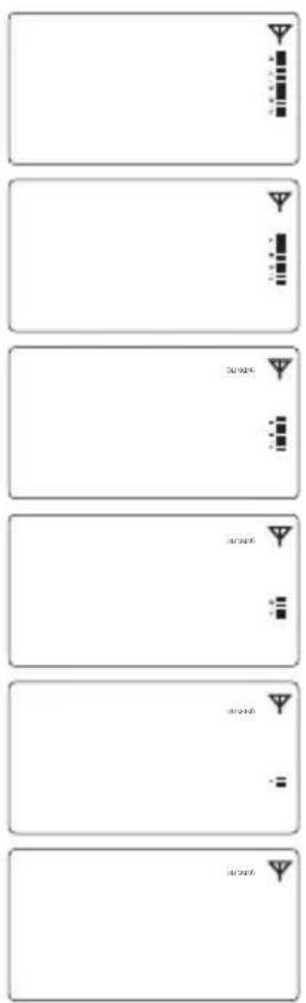
Correct Antenna install with 5W
VSWR 1.2 with 4.5W
VSWR 2.6 with 4W
VSWR 3.5 with 3.5W
VSWR 4.4 with 3W
< 3W
The VSWR and Power test can vary depending on installation conditions. If TPI feature is turned off in the settings menu, the TPI indicator will show 5 bars during TX.
If an incorrect or no antenna is connected and power output is less than 3.5W, “ANT-X” will be displayed when TPI feature is turned on or off. When “ANT-X” is displayed, the radio has enabled protection mode and reduced RF output.
Scan resume time
You can select 5, 10, or 15 sec depending on your selection. SCAN will start again after a 5, 10, or 15 sec pause even though a signal is still present.
If P5 is selected, SCAN will stop on all channels as long as a signal is present. It will then resume SCAN again 5 seconds after no transmission is present.
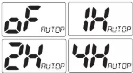
Auto power OFF
The auto power off function is activated when no transmitting and no key function is present for the time selected.
The automatic power off time can be adjusted to OFF, 1, 2, or 4 hours in menu mode.
UHF CB channels and frequencies
| Channel | TxFreqMHZ | RxFreqMHz | Channel | TxFreqMHz | RxFreqMHz | ||
| 01* | 476.4250 | 476.4250 | 21 | 476.9250 | 476.9250 | ||
| 41* | - | 476.4375 | 61‡ | - | - | ||
| 02* | 476.4500 | 476.4500 | 22† | 476.9500 | 476.9500 | ||
| 42* | - | 476.4625 | 62‡ | - | - | ||
| 03* | 476.4750 | 476.4750 | 23† | 476.9750 | 476.9750 | ||
| 43* | - | 476.4875 | 63‡ | - | - | ||
| 04* | 476.5000 | 476.5000 | 24 | 477.0000 | 477.0000 | ||
| 44* | - | 476.5125 | 64 | 477.0125 | 477.0125 | ||
| 05* | 476.5250 | 476.5250 | 25 | 477.0250 | 477.0250 | ||
| 45* | - | 476.5375 | 65 | 477.0375 | 477.0375 | ||
| 06* | 476.5500 | 476.5500 | 26 | 477.0500 | 477.0500 | ||
| 46* | - | 476.5625 | 66 | 477.0625 | 477.0625 | ||
| 07* | 476.5750 | 476.5750 | 27 | 477.0750 | 477.0750 | ||
| 47* | - | 476.5875 | 67 | 477.0875 | 477.0875 | ||
| 08* | 476.6000 | 476.6000 | 28 | 477.1000 | 477.1000 | ||
| 48* | - | 476.6125 | 68 | 477.1125 | 477.1125 | ||
| 9 | 476.6250 | 476.6250 | 29 | 477.1250 | 477.1250 | ||
| 49 | 476.6375 | 476.6375 | 69 | 477.1375 | 477.1375 | ||
| 10 | 476.6500 | 476.6500 | 30 | 477.1500 | 477.1500 | ||
| 50 | 476.6625 | 476.6625 | 70 | 477.1625 | 477.1625 | ||
| 11 | 476.6750 | 476.6750 | 31* | 477.1750 | 477.1750 | ||
| 51 | 476.6875 | 476.6875 | 71* | 477.1875 | - | ||
| 12 | 476.7000 | 476.7000 | 32* | 477.2000 | 477.2000 | ||
| 52 | 476.7125 | 476.7125 | 72* | 477.2125 | - | ||
| 13 | 476.7250 | 476.7250 | 33* | 477.2250 | 477.2250 | ||
| 53 | 476.7375 | 476.7375 | 73* | 477.2375 | - | ||
| 14 | 476.7500 | 476.7500 | 34* | 477.2500 | 477.2500 | ||
| 54 | 476.7625 | 476.7625 | 74* | 477.2625 | - | ||
| 15 | 476.7750 | 476.7750 | 35* | 477.2750 | 477.2750 | ||
| 55 | 476.7875 | 476.7875 | 75* | 477.2875 | - | ||
| 16 | 476.8000 | 476.8000 | 36* | 477.3000 | 477.3000 | ||
| 56 | 476.8125 | 476.8125 | 76* | 477.3125 | - | ||
| 17 | 476.8250 | 476.8250 | 37* | 477.3250 | 477.3250 | ||
| 57 | 476.8375 | 476.8375 | 77* | 477.3375 | - | ||
| 18 | 476.8500 | 476.8500 | 38* | 477.3500 | 477.3500 | ||
| 58 | 476.8625 | 476.8625 | 78* | 477.3625 | - | ||
| 19 | 476.8750 | 476.8750 | 39 | 477.3750 | 477.3750 | ||
| 59 | 476.8875 | 476.8875 | 79 | 477.3875 | 477.3875 | ||
| 20 | 476.9000 | 476.9000 | 40 | 477.4000 | 477.4000 | ||
| 60 | 476.9125 | 476.9125 | 80 | 477.4125 | 477.4125 | ||
* The primary use for these channels is repeater operation using 750 kHz offset. Channels 1-8 inclusive are used for mobile reception and channels 31-38 for mobile transmission. Note that additional channels 41-48 and 71-78 are also available for repeater operation to supplement channels 1-8 and-31-38 respectively as approved by the ACMA CBRS Class Licence in Australia and the MED GURL in New Zealand. In addition, any designated repeater channel may be used for simplex operation in areas where it is not used for repeater operation.
† Speech telephony shall be inhibited on these channels.
‡ At the time of production Channels 61, 62 and 63 are guard channels and are not available for use.
Channels 5 and 35 (paired for Duplex repeaters) are reserved as emergency channels and should be used only in an emergency.
CTCSS and DCS will not operate on these channels.
A list of currently authorised channels can be obtained from the ACMA website in Australia and the MED website in New Zealand. Channel 11 is a calling channel generally used to call others and channel 40 is the customary road vehicle channel.
Once contact is established on the calling channel, both stations should move to another unused "SIMPLEX" channel to allow others to use the calling channel.
UHF CB Radios normally transmit and receive on the same frequency which is known as the simplex operation.
Channels 22 and 23 are for Telemetry and Telecommand use, voice communications are not allowed on these channels by law.
Channel 9 and above are the best choices for general use in Simplex mode.
38 CTCSS CODE LIST
| CODE Frequency(Hz) CODE Frequency(Hz) | |||
| OFF OFF 20 | 131.8 | ||
| 1 67.0 21 | 136.5 | ||
| 2 71.9 22 | 141.3 | ||
| 3 74.4 23 | 146.2 | ||
| 4 77.0 24 | 151.4 | ||
| 5 79.7 25 | 156.7 | ||
| 6 82.5 26 | 162.2 | ||
| 7 85.4 27 | 167.9 | ||
| 8 88.5 28 | 173.8 | ||
| 9 91.5 29 | 179.9 | ||
| 10 94.8 30 | 186.2 | ||
| 11 97.4 31 | 192.8 | ||
| 12 100.0 | 32 203.5 | ||
| 13 103.5 | 33 210.7 | ||
| 14 107.2 | 34 218.1 | ||
| 15 110.9 | 35 225.7 | ||
| 16 114.8 | 36 233.6 | ||
| 17 118.8 | 37 241.8 | ||
| 18 123.0 | 38 250.3 | ||
| 19 127.3 | |||
DCS codes table
| Code NO. | DCS Code (Octal) | Code NO. | DCS Code (Octal) | Code NO. | DCS Code (Octal) |
| 1 | 023 | 36 | 223 | 71 | 445 |
| 2 | 025 | 37 | 225 | 72 | 446 |
| 3 | 026 | 38 | 226 | 73 | 452 |
| 4 | 031 | 39 | 243 | 74 | 454 |
| 5 | 032 | 40 | 244 | 75 | 455 |
| 6 | 036 | 41 | 245 | 76 | 462 |
| 7 | 043 | 42 | 246 | 77 | 464 |
| 8 | 047 | 43 | 251 | 78 | 465 |
| 9 | 051 | 44 | 252 | 79 | 466 |
| 10 | 053 | 45 | 255 | 80 | 503 |
| 11 | 054 | 46 | 261 | 81 | 506 |
| 12 | 065 | 47 | 263 | 82 | 516 |
| 13 | 071 | 48 | 265 | 83 | 523 |
| 14 | 072 | 49 | 266 | 84 | 526 |
| 15 | 073 | 50 | 271 | 85 | 532 |
| 16 | 074 | 51 | 274 | 86 | 546 |
| 17 | 114 | 52 | 306 | 87 | 565 |
| 18 | 115 | 53 | 311 | 88 | 606 |
| 19 | 116 | 54 | 315 | 89 | 612 |
| 20 | 122 | 55 | 325 | 90 | 624 |
| 21 | 125 | 56 | 331 | 91 | 627 |
| 22 | 131 | 57 | 332 | 92 | 631 |
| 23 | 132 | 58 | 343 | 93 | 632 |
| 24 | 134 | 59 | 346 | 94 | 654 |
| 25 | 143 | 60 | 351 | 95 | 662 |
| 26 | 145 | 61 | 356 | 96 | 664 |
| 27 | 152 | 62 | 364 | 97 | 703 |
| 28 | 155 | 63 | 365 | 98 | 712 |
| 29 | 156 | 64 | 371 | 99 | 723 |
| 30 | 162 | 65 | 411 | 100(do0) | 731 |
| 31 | 165 | 66 | 412 | 101(do1) | 732 |
| 32 | 172 | 67 | 413 | 102(do2) | 734 |
| 33 | 174 | 68 | 423 | 103(do3) | 743 |
| 34 | 205 | 69 | 431 | 104(do4) | 754 |
| 35 | 212 | 70 | 432 |
Express Warranty (Australia)
This Express Warranty is provided by Oricom International Pty Ltd ABN 46086 116 369, Unit 1, 4 Sovereign Place, South Windsor NSW 2756, herein after referred to as “Oricom”.
Oricom warrants that the product is free from defects in materials or workmanship during the Express Warranty Period. This Express Warranty does not extend to any product from which the serial number has been removed or was purchased outside of Australia.
The benefits of this Express Warranty are in addition to other rights and remedies you may have under the Australian Consumer Law. Our goods come with guarantees that cannot be excluded under the Australian Consumer Law. You are entitled to a replacement or refund for a major failure and compensation for any other reasonably foreseeable loss or damage. You are also entitled to have the goods repaired or replaced if the goods fail to be of acceptable quality and the failure does not amount to a major failure. In the event of a minor failure, Oricom reserves the right to choose to repair or replace the product.
The Express Warranty Period will be a period of 5 years beginning on the date of purchase of the product evidenced by your dated sales receipt. You are required to provide proof of purchase as a condition of receiving Express Warranty services.
You are entitled to a replacement product or repair of the product at our discretion according to the terms and conditions of this document if your product is found to be faulty within the Express Warranty Period. This Express Warranty extends to the original purchaser only and is not transferable.
Products distributed by Oricom are manufactured using new materials or new and used materials equivalent to new in performance and reliability. Spare parts may be new or equivalent to new. Spare parts are warranted to be free from defects in material or workmanship for thirty (30) days or for the remainder of the Express Warranty Period of the Oricom branded product in which they are installed, whichever is longer. During the Express
Warranty Period, Oricom will where possible repair and if not replace the faulty product or part thereof. All component parts removed under this Express Warranty become the property of Oricom. In the unlikely event that your Oricom product has a recurring failure, Oricom may always, subject to the Competition and Consumer Act 2010, at its discretion, elect to provide you with a replacement product of its choosing that is at least equivalent to your product in performance.
No change to the conditions of this Express Warranty is valid unless it is made in writing and signed by an authorised representative of Oricom.
Oricom will not be liable under this Express Warranty, and to the extent permitted by law will not be liable for any defect, loss, damage or injury arising out of or in connection with a:
- Failure by you to adhere to the warnings and follow the instructions set out in this user guide for the proper installation and use of the product;
- Willful misconduct or deliberate misuse by you of the product;
- Any external cause beyond our control, including but not limited to power failure, lightning or over voltage; or
- Modification to the product or services carried out on the product by anyone other than Oricom or Oricom's authorised service provider.
How to make a claim under your Express Warranty in Australia
Oricom has a simple warranty process for you to follow:
- Please call or email our Customer Support Team, 02 4574 8888 or support@oricom.com.au.
- A Customer Support Team member will verify after troubleshooting with you if your product qualifies under warranty. If so, they will give you a Product Return Authorisation number.
- We will then email a Return Authorisation form and a Repair Notice (if necessary), together with instructions on how to return the product for warranty service.
Please note that if a Customer Support Team member advises that your product does not qualify for return, this warranty does not apply to your product. Products that are authorised to be returned to Oricom in Australia must include all of the following:
• A completed Return Authorisation form
- A copy of your Proof of Purchase (please keep your original copy)
- The faulty product, including all accessories.
Send the approved returns to:
Oricom International Pty Ltd
Locked Bag 658
South Windsor NSW 2756 Australia
Please note that this Express Warranty excludes expenses incurred by you in returning any faulty product to us. You must arrange and pay any expenses incurred (including postage, delivery, freight, transportation or insurance of the product) to return the faulty product to us, however, we will arrange delivery of the repaired or replaced faulty product to you.
Important Information
Repair Notice
Please be aware that the repair of your products may result in the loss of any user-generated data (such as stored telephone numbers, text messages and contact information). Please ensure that you have made a copy of any data saved on your product before sending for repair. Please also be aware that products presented for repair may be replaced by refurbished products or parts of the same type rather than being repaired.
ORICOM CUSTOMER SUPPORT
Oricom have a trained and dedicated team of Customer Support Representatives, each with the knowledge and resources to assist in answering your questions quickly and efficiently.
Oricom Support - Australia
For all product enquiries, troubleshooting or to discuss the range of Oricom products, feel free to contact Oricom or visit our website for answers to frequently asked questions.
(02) 4574 8888
Monday - Friday 8am – 6pm AEST
Email: support@oricom.com.au
www.oricom.com.au
Oricom Support - New Zealand
0800 674 266
Monday - Friday 11am - 7pm NZST
Email: support@oricom.co.nz

Ref:17052023
- Operating Instructions
- R-NZ
- Need Help?
- Introduction
- Key Features
- Optional Accessories (See page 7 for details)
- Please read before installing or operating your Oricom Radio
- Safety Information and Warnings
- Potentially Explosive Atmospheres
- Blasting Caps and Areas
- Electromagnetic Interference/Compatibility
- CAUTION
- Wiring Methods
- Radio stays ON when the ignition is switched OFF
- Radio turns OFF with the ignition switch
- Antenna information
- Antenna installation
- Optional Accessories
- Optional Magnetic Microphone Holder
- Optional External Speaker
- Controls and Indicators
- Front View
- Rear View
- LCD Icons & Indicators
- Installation of the DTX4200XP and fitting optional accessories
- Mounting the UHF radio
- Installation Diagram
- Operations
- Turning on the Power
- Setting the Volume
- Selecting a channel
- Setting the Squelch Level
- PTT (Push-To-Talk) button
- Scanning
- Open scan
- Remove Memory in Scanning
- Group Memory Scan
- Group Tone Scan
- Memory Recall
- Memory Write
- SWP (Swapping Dual RX channel)
- SRX On/Off
- Menu list
- Duplex
- General
- CTCSS and DCS setting
- Group Tone setting
- Multi-colour Backlight
- Backlight dimmer
- Factory Reset
- Squelch Tail
- Busy channel Lock
- Key Beep
- Logo Display
- TPI
- Scan resume time
- Auto power OFF
- Express Warranty (Australia)
- How to make a claim under your Express Warranty in Australia
- Important Information
- Repair Notice
- ORICOM CUSTOMER SUPPORT
- Oricom Support - Australia
- 4574 8888
- 674 266
Brand : Oricom
Model : DTX4200XP
Category : Walkie-talkie