Z-Dim2 - Dimmer Heatit - Free user manual and instructions
Find the device manual for free Z-Dim2 Heatit in PDF.


| Product Type | Z-Wave Rotary Dimmer |
| Brand | Heatit |
| Model | Z-Dim2 |
| Dimensions (L x W x H) | 84 x 84 x 43 mm |
| Flush Mounting Depth | 24 mm |
| Rated Voltage | 230 VAC, 50 Hz |
| Power Rating | 5 W - 250 W (LED) |
| Input Current | 1.1 A |
| Protocol | Z-Wave Plus V2, 868.4 MHz |
| Chip | Z-Wave 700 |
| RF Range | Min. 40 m (indoors) |
| Connection Max. Wire Size | 2.5 mm² |
| IP Code | IP21 |
| Ambient Temperature | 5 °C to 40 °C |
| Color | White RAL 9003 & RAL 9010 |
| Approvals | Z-Wave Plus V2, CE, Nemko |
| Power Metering | Yes (kWh and Watt) |
| SmartStart Support | Yes |
| Firmware Update (OTA) | Yes |
| External Switch Input | Yes (momentary NO) |
| Dimming Curves | Linear or Logarithmic |
| Dimming Edge | Leading or Trailing |
| Protections | Overload, Short Circuit, Surge, Overheat |
| Autocalibration of Max Dim Level | Yes |
| Maintenance | Maintenance-free, do not cover |
Frequently Asked Questions - Z-Dim2 Heatit
User questions about Z-Dim2 Heatit
0 question about this device. Answer the ones you know or ask your own.
Ask a new question about this device
Download the instructions for your Dimmer in PDF format for free! Find your manual Z-Dim2 - Heatit and take your electronic device back in hand. On this page are published all the documents necessary for the use of your device. Z-Dim2 by Heatit.
USER MANUAL Z-Dim2 Heatit
TABLE OF CONTENTS
- Introduction
- Statement regarding products from multiple manufacturers
- Behaviour within the Z-Wave™ network
- Quick Start
- Control
- Illustrations
- Installation and wiring
- External Switch
- Add/Remove
9.1 Method 1: Standard (Manual)
9.2 Method 2: SmartStart (Automatic)
-
Factory Reset
-
Startup
-
LED blinking patterns description
-
QR-Code Placement (DSK)
-
Security
-
Node Information Frame
-
Associations
16.1 Setting and Removing Associations
-
Association Groups
-
Configuration Parameters
-
Autocalibration of maximum dim level
-
Command Classes
20.1 Basic Command Class
20.2 Multilevel Switch Command Class
20.3 Meter Command Class
20.4 Indicator Command Class
20.5 Central Scene Command Class
- Supported Command Classes Product info
1. INTRODUCTION
Heatit Z-Dim2 is a Z-Wave ^™ rotary dimmer for many different types of light fixtures. The Heatit Z-Dim2 works on most low loads without causing flickering.
The dimmer is equipped with an external switch option. This allows you to dim and turn on/off the load from an external switch.
Heatit Z-Dim2 is very well suited for LED, and fits into System 55 frames. When connecting low loads it is recommended to use a bypass.
NB! DIMMING
Dimming may be challenging, and we recommend checking the compatibility of different light sources before installation. We are happy to answer any questions.
2. STATEMENT REGARDING PRODUCTS FROM MULTIPLE MANUFACTURERS
Please read this before installation
This device may be used with all devices certified with the Z-Wave Plus™ certificate and should be compatible with such devices produced by any manufacturer. Every primary controller is different depending on the manufacturer, their target audience and intended use/application. Please review the functionalities implemented by the primary controller you intend to use with our Z-Wave Plus certified device to ensure that it provides the necessary controls to take full advantage of our product's capabilities.
3. BEHAVIOUR WITHIN THE Z-WAVE™ NETWORK
This device may be operated within any Z-Wave network with Z-Wave-certified devices from other manufacturers. All non-battery-operated nodes within the network will act as repeaters regardless of manufacturer to increase the reliability of the network. On delivery, the device does not belong to any Z-Wave network. The device needs to be added to an existing network to communicate with the other devices within it. Devices may also be removed from a network. The add/remove processes are initiated by the primary controller of the Z-Wave network.
4. QUICK START
- Switch off the mains voltage (turn off the fuse).
- Open the junction box.
- Connect according to the wiring diagram as shown in chapter 7 "Installation & wiring".
- After verifying the connections, switch on the mains voltage.
- Set the primary controller in add mode (security/non-security).
- Press the reset button on dimmer 3 times in a rapid sequence. Heatit Z-Dim2 is now included in your Z-Wave network.
5. CONTROL
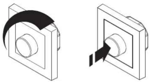
natural_image
Technical illustration of two mechanical components with curved arrows indicating motion (no text or symbols)Increase / decrease On / Off
6. ILLUSTRATIONS
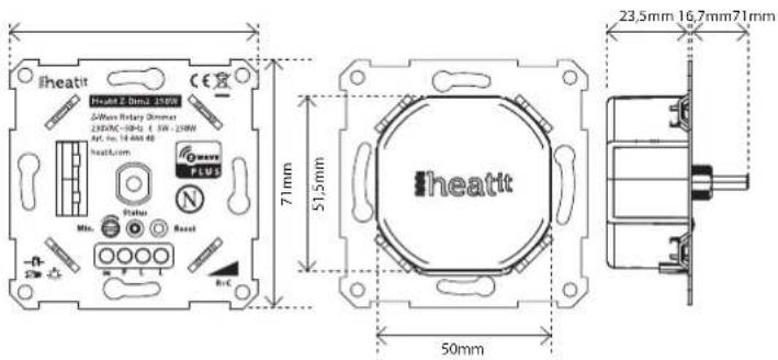
7. INSTALLATION AND WIRING
Installation must be done by a qualified electrical installer in accordance with the national building codes. Before installation, disconnect any power to the dimmer mains. During the installation process, the fuse must be turned off AT ALL TIMES!
NB! Max tightening torque for terminal screws: 2Nm
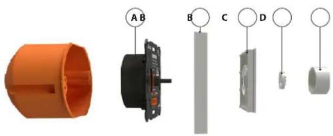
NB! This is a 2-wire dimmer so the Neutral is only connected to the load and not the dimmer itself.
- Turn off the fuse.
- Connect the Live to the dimmer terminal marked "L".
-
Connect the load terminal marked "L" to the dimmer terminal marked
-
Install the dimmer (A) in the wall box. Make sure that no wires are pinched.
-
Attach the cover (B) with the supplied nut (C).
-
Attach the button (D) with a simple push.
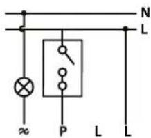
Wiring diagram
S1: Dimmer knob. Can be used as a scene controller.
S2: External switch connected to P. Used for either dimming or scene controller.
8. EXTERNAL SWITCH
Momentary Switch (NO)
When using a momentary switch, the switch functionality can be selected using Parameter 7. The switch must be a normally open switch.
9. ADD/REMOVE
Please read this before installation
The primary controller/gateway has a mode for adding or removing devices. Please refer to your primary controller manual on how to set the primary controller in add/remove mode. The device may only be added or removed from the network if the primary controller is in add/remove mode. When the device is removed from the network, it will NOT revert to factory settings.
There are two ways to add the device to a Z-Wave network.
9.1 Method 1: Standard (Manual)
Add/remove mode is indicated on the device by a blinking green LED. It indicates this for 90 seconds until a timeout occurs, or until the module has been added to/removed from the network.
To start the configuration process press the Reset button, or the external switch connected to P, 3 times in rapid succession. The LED will blink green for 3 seconds if adding/removing is successful. The device is now ready for use with default settings.
NB! When the device is removed from the gateway, the parameters are not reset. To reset the parameters, see Chapter 10 "Factory reset".
If inclusion fails, please perform a "remove device" process and try again. If inclusion fails again, please see Chapter 10 "Factory reset".
9.2 Method 2: SmartStart (Automatic)
SmartStart enabled products may be added to a Z-Wave network by scanning the Z-Wave QR-Code on the product if your primary controller supports SmartStart inclusion. No further action is required and the SmartStart product will be added automatically after being powered on within range of the primary controller.
10. FACTORY RESET
Please read this before installation
Press and hold the reset button. After 3 seconds the LED will start to blink in green. After 20 seconds the LED will shine solid green for 3 seconds. You may now release the button.
Please attempt exclusion before using factory reset.
11. STARTUP
After powering up the device for the first time, all the parameters will have default settings.
12. LED BLINKING PATTERNS DESCRIPTION
The device supports numerous LED blinking patterns to make it as easy as possible to identify what the device is doing.
| Device Not in NetworkThe LED will flash in red when the device is not added to a Z Wave network. | 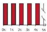 |
| Add/RemoveWhen device enters adult/remove mode the LED will flash green.If successful, the LED will light up in green for 3 seconds.If unsuccessful, the LED will light up in red for 3 seconds. | 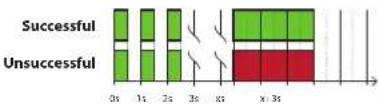 |
| Factory ResetIf the button is pressed for more than 3 seconds, the GREEN LED will start flashing.When the button has been pressed for 20 seconds, the GREEN LED will light up for 3 seconds.Figure 1 (success)Within the 3 second period the button must be released.If the button is released within this period, the device will reset and start flashing because it is not included in a gateway.Figure 2 (fail)If the button is released before the 3 second period, the device will indicate fail by turning RED LED on for 3 seconds.Figure 3 (fail)The button MUST be released between 20 and 23 seconds for local reset to take place. It had longer, the device will grow the command. | Figure 1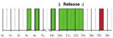 Figure 2 Figure 2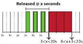 Figure 3 Figure 3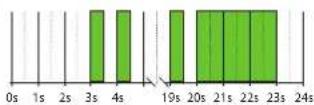 |
13. QR-CODE PLACEMENT (DSK)
The QR-Code is needed when including a device using S2 security or SmartStart. The DSK can be found in the QR-Code and is located;
- On the product.
• On the Quick Guide. - On the gift box.
14. SECURITY
S2 security enhances Z-Wave Plus with an additional layer of AES 128-bit encryption of the wireless Z-Wave communication to prevent hacking and man-in-middle attacks on the home network. This device supports S2 and has a Z-Wave DSK QR-Code label that may be used when the module is added to the Z-Wave home network. The primary controller will ask for a 5-digit code, which can be found underneath the QR-Code. The primary controller will then ask you to confirm the rest of the code that is contained in the QR-Code.
15. NODE INFORMATION FRAME
The node information frame is the "business card" of a Z-Wave device. It contains information about the device type and its technical features. The add and remove procedure of the device is confirmed by sending out a node information frame. Besides this, it may be necessary for certain network operations to send out a node information frame.
16. ASSOCIATIONS
Z-Wave devices interact with other Z-Wave devices. The relationship between one device controlling another device is called an association. In order to control a subordinate device, the controlling device needs to maintain a list of devices that will receive controlling commands. These lists are called "Association Groups". They are always related to the specific event triggered (e.g., sensor reports). In case the event is triggered, all devices stored in the respective association group will receive a joint wireless command.
16.1 Setting and Removing Associations
Associations may be assigned and removed via Z-Wave commands. Please refer to your primary controller/Z-Wave gateway for more information.
- ASSOCIATION GROUPS
| MULTI LEVEL SWITCH DEVICE DESCRIPTION | |
| Group 1Lifeline | Lifetime (Normally used by the Z-Wave Controller) Sends- Switch Multilevel Report- Device Reset Notification- Indicator Report- Meier Report- Central Scene Notification- Configuration ReportMax nodes in group: 5 |
| Group 2Basic Set | -Basic SetSend Basic Set commands representing the status of the dimmer when changed from S1 or S2CH-OR (0x00, 0x1)1.99% (0x01, 0x63)Max nodes in group: 5 |
| Group 3Switch Multilevel | Switch MultilevelWhen S1 or S2 is pressed/heldPress OFF-ON (0x00, 0xFF)Hold Multilevel Switch Start Level Change/Stop Level Change CommandLevel Increase Start / Level Increase StopLevel Decrease Start / Level Decrease StopMax nodes in group: 5 |
18. CONFIGURATION PARAMETERS
Z-Wave products are supposed to work out of the box after inclusion. Some device configuration may, however, alter the functionality to better serve user needs or unlock further enhanced features. All the parameters below do not feature altering capabilities, advanced or read only flag.
| PARA NOA | PARA SIZE (BYTE) NAME | SHORT DESCRIPTION /COMMENT MIN MAX DEFAULT | DESCRIPTION OF VALUE | |||
| 1 ° Power restore | level | The state the dimmer should return to once power is restored after a power failure. | 0.0 100 Off | 1% 99% | ||
| 1.99 | ||||||
| 100 | 100 | |||||
| 0.0 0 Restores last c/m level | Returns to level before power outage (Default) | |||||
| 1.99 | ||||||
| 2 ° Switch ON | level | Det net the dimming level when restored from the OFF state. | 0.0 0 Auto OFF disabled | Default | (Default) | |
| 1.86400 | ||||||
| 0.0 0 Auto Off disabled | Default | 1.86400 seconds | ||||
| 3.4 Automatic | turn Off | Time for the dinner to turn off automatically after turning it on. | 0.0 0 Auto Off disabled | Duration | 1.86400 seconds | |
| 1.86400 | ||||||
| 4.4 Automatic | turn ON | Time for the dinner to turn on automatically after turning it off. | 0.0 0 Auto ON disabled | Duration | 1.86400 seconds | |
| 1.86400 | ||||||
| 5 ° Turn off delay | time | The time it takes before the dinner turns off after turning it off. | 0.0 0 Disabled (Default) | Duration | ||
| 1.60 | ||||||
| 1.60 | ||||||
| PARA NO# | PARA SIZE (BYTE) NAME | SHORT DESCRIPTION/COMMENT MIN MAX DEFAULT | DESCRIPTION OF VALUE | ||||
| 5.1 Rotary | wheel press functionality | Decide the rotary wheel press function. | 3 0 0 Double click to 10% | (Default) | |||
| 1 1 Scene controller function | |||||||
| 2 2 Disabled | |||||||
| 7 1 External | switch functionality | Decide how external switch function. | 3 0 1 Double click to 10% | external switch pair and dimming | |||
| 1 1 Scene controller function | (Default) | ||||||
| 2 2 Disabled | |||||||
| 8 1 Dimming | duration | Define how long it leaves to dim when using the external switch. | 3 0 50 Instantly | sec | |||
| 1 100 1-120=0 1-10 | (Default 5 seconds) | ||||||
| 9 1 Choose the | dimmer curve | Choose if the dimmer uses Linear or Logarithmic dimming. | 3 0 0 Linear dimming (Default) | ||||
| 1 1 Logarithmic dimming | |||||||
| 10 1 Load | dimming mode | Choose the dimming type. 0 | 3 0 Trailing edge (Default) | ||||
| 1 1 Leading edge | |||||||
| 11 1 Maximum | dim level | Highest dim level of the dimmer. | 2 59 90 2% 99% | (Default 90) | |||
| If the dimmer stops working after adjusting this parameter, turn off and on the power to the device and let it recalibrate. | |||||||
| 12 1 Meter report | threshold | Threshold for device to send meter report in W. | 3 0 10 D sales | 10W | |||
| 1 250 1-250W (Default) | |||||||
| 13 2 Meter report | interval | Time interval between consecutive meter reports in seconds. | 30 63535 780 30-805 5 sec. (Default 780) | ||||
19. AUTOCALIBRATION OF MAXIMUM DIM LEVEL
The dimmer supports an autocalibration feature for the maximum dim level. Autocalibration will initiate if the dimmer detects flickering.
The Maximum dim level Parameter (11) will be updated automatically upon completion of the autocalibration. The value will also be reported to the gateway.
20. COMMAND CLASSES
Besides the mandatory command classes, the device has support for the following command classes:
20.1 Basic Command Class
Basic Set commands are mapped to Multilevel Switch and are also used to control the dimming level and associated devices in group 2.
Uses the following values:
$$ 0 \times 0 0 = O F F $$
$$ 0 \times F F = O N $$
$$ 0 \times 01... 0 \times 63 = 1 \% - 99 \% $$
20.2 Multilevel Switch Command Class
Multilevel Switch commands are used to control the dimming level and associated devices in group 3.
Uses the following values:
$$ 0 \times 0 0 = O F F $$
$$ 0 x F F = O N $$
$$ 0 \times 0 1 \dots 0 \times 6 3 = 1 \% - 99 \% $$
20.3 Meter Command Class
The device supports Meter Command Class Get, and the dimmer will only respond on supported electric meter scales:
kWh (accumulated) and Watt (instant).
The device will report when asked:
Rate import: Import (0x01)
Meter type: Electric meter (0x01)
Precision: 2 decimals (0x02)
| PRECISION VALUE | SCALE SUPPORTED (VALUE) | SIZE |
| 2 declines (2x02) | G × 10^40 | 4 |
| 2 declines (2x02) | W × 2 × 02 | 2 |
20.4 Indicator Command Class
The device supports Indicator Command Class.
The indicator Command Class will turn ON/OFF internal LED as wanted as well as turning the load ON/OFF.
20.5 Central Scene Command Class
The device supports the Central Scene Command Class. This command class is used to perform actions chosen in the controller.
To use the Scene controller functionality from the rotary knob, set Parameter 6 (Rotary wheel press functionality) to 1 (Scene controller function).
The following attributes are supported:
| BUTTON | SCENE NUMBER | KEY ATTRIBUTE | DESCRIPTION |
| S1 (Folary knob) 1 | 0x00 | Pressed 1 time | |
| 0x01 | Released (send only after button was held) | ||
| 0x02 | Held down (send only when held for more than 700ms) | ||
| 0x03 | Pressed 2 times | ||
| 0x04 | Pressed 3 times | ||
| 0x05 | Pressed 4 times | ||
| 0x06 | Pressed 5 times | ||
| S2 (External switch) | 2 | 0x00 | Pressed 1 time |
| 0x01 | Released (send only after button was held) | ||
| 0x02 | Held down (send only when held for more than 700ms) | ||
| 0x03 | Pressed 2 times | ||
| 0x04 | Pressed 3 times | ||
| 0x05 | Pressed 4 times | ||
| 0x06 | Pressed2 times | ||
21. SUPPORTED COMMAND CLASSES
The following table lists all Command Classes supported by the Z-Wave device. The device supports S0, S2 Authenticated security and S2 Unauthenticated security.
| VERSION | INSECURE ON SECURE INCLUSION | SECURE ON SECURE INCLUSION | |
| Application Status | 1 | Yes | |
| Association | 2 | Yes | |
| Association Group Information | 3 | Yes | |
| Basic | 2 | Yes | |
| Configuration | 4 | Yes | |
| Device Reset Locally | 1 | Yes | |
| Firmware Update | 5 | Yes | |
| Manufacturer Specific | 3 | Yes | |
| Motor | 3 | Yes | |
| Multichand Association | 3 | Yes | |
| Powerlevel | 1 | Yes | |
| Security | 1 | Yes | |
| Security 2 | 1 | Yes | |
| Supervision | 1 | Yes | |
| Switch Multilevel | 4 | Yes | |
| Indicator | 3 | Yes | |
| Transport Service | 2 | Yes | |
| Version | 3 | Yes | |
| Z-Wave Plus Information | 2 | Yes | |
| Central Score | 3 | Yes |
PRODUCT INFO Heatit Z-Dim2 250W
FEATURES
• Z-Wave rotary dimmer
- 2-wire
- 5W - 250W LED
- Power metering
- SmartStart
- Firmware update (OTA)
- Overload protection
- Short circuit protection
- Surge protection
• Overheat protection
- External switch
- Min. dim level
• Max. dim level auto-calibration
• Supports encryption mode S0, S2 Authenticated Class, S2 Unauthenticated Class
This product is a security-enabled Z-Wave Plus product with encryption. The product must be used with a security-enabled Z-Wave Controller in order to fully utilize the product.
NB! Dimming may be challenging, and we recommend checking the compatibility of different light sources before installation.
TECHNICAL DATA
Protocol Z-Wave, 868.4MHz
Chip Z-Wave 700 chip
Rated voltage 230VAC 50Hz
Power 5W - 250W
Input current 1.1A
Controls Rotary and push dimming
Ambient temperature 5°C to 40°C
Range RF Min. 40 meter
Connection Max. 2.5mm ^4
Flush mounting depth 24mm
IP Code IP 21
Size (LxWxH) 84 x 84 x 43mm
Approvals Z-Wave Plus V2, CE, Nemko
Working frequency 868.4MHz, Max output power 12.49dBm
The distance between user and products should be no less than 20 cm.
MAINTENANCE
The device is maintenance-free, but must never be covered.
Only for indoor installation.
| ART. NO. | PRODUCT | COLOR | FREQUENCY |
| 14 444 40 | Heatit Z-Dim2 250W | White RAL 9003 & RAL 9010 | EU 868.4MHz |
Heatit Controls AB can not be held liable for typographical errors, other errors or omitances in our information. Product specifications may change without further notice. All electrical installations must be carried out by a licensed electrician. The product must be installed in accordance with national building codes and our installers manual.

CONTROLS
- TABLE OF CONTENTS
- INTRODUCTION
- NB! DIMMING
- STATEMENT REGARDING PRODUCTS FROM MULTIPLE MANUFACTURERS
- Please read this before installation
- BEHAVIOUR WITHIN THE Z-WAVE™ NETWORK
- QUICK START
- CONTROL
- ILLUSTRATIONS
- INSTALLATION AND WIRING
- NB! Max tightening torque for terminal screws: 2Nm
- NB! This is a 2-wire dimmer so the Neutral is only connected to the load and not the dimmer itself.
- EXTERNAL SWITCH
- Momentary Switch (NO)
- ADD/REMOVE
- Method 1: Standard (Manual)
- Method 2: SmartStart (Automatic)
- FACTORY RESET
- STARTUP
- LED BLINKING PATTERNS DESCRIPTION
- QR-CODE PLACEMENT (DSK)
- SECURITY
- NODE INFORMATION FRAME
- ASSOCIATIONS
- Setting and Removing Associations
- CONFIGURATION PARAMETERS
- AUTOCALIBRATION OF MAXIMUM DIM LEVEL
- COMMAND CLASSES
- Basic Command Class
- Multilevel Switch Command Class
- Meter Command Class
- Indicator Command Class
- Central Scene Command Class
- SUPPORTED COMMAND CLASSES
- PRODUCT INFO Heatit Z-Dim2 250W
- FEATURES
- TECHNICAL DATA
- MAINTENANCE
Brand : Heatit
Model : Z-Dim2
Category : Dimmer