
DV-18023H - LED Screen Newline - Free user manual and instructions
Find the device manual for free DV-18023H Newline in PDF.


| Product Type | LED Interactive Display |
| Model | DV-18023H |
| Brand | Newline |
| Screen Size | 86 inches (diagonal) |
| Resolution | 3840 x 2160 (4K UHD) |
| Brightness | 350 cd/m² |
| Contrast Ratio | 4000:1 |
| Aspect Ratio | 16:9 |
| Viewing Angle | 178° (horizontal and vertical) |
| Response Time | 8 ms |
| Touch Points | 20 points (projected capacitive) |
| Input Ports | HDMI 2.0 (x3), USB 3.0 (x2), VGA, Audio In |
| Output Ports | HDMI, Audio Out, USB Touch |
| Power Supply | AC 100-240V, 50/60Hz |
| Power Consumption | ≤350 W (typical) |
| Standby Power | <0.5 W |
| Dimensions (W x H x D) | 1957 x 1170 x 88 mm (without stand) |
| Weight | Approx. 55 kg |
| Operating Temperature | 0°C to 40°C |
| Cleaning | Use a soft, dry cloth. Avoid harsh chemicals or abrasive materials. |
| Safety Precautions | Connect to a grounded power outlet. Do not expose to water or high humidity. Do not insert objects into ventilation gaps. |
| Spare Parts & Repairability | Contact authorized Newline service centers for genuine spare parts. Repairs should be carried out by qualified technicians. |
Frequently Asked Questions - DV-18023H Newline
User questions about DV-18023H Newline
0 question about this device. Answer the ones you know or ask your own.
Ask a new question about this device
Download the instructions for your LED Screen in PDF format for free! Find your manual DV-18023H - Newline and take your electronic device back in hand. On this page are published all the documents necessary for the use of your device. DV-18023H by Newline.
USER MANUAL DV-18023H Newline
Newline DV All-in-one Direct View LED Display

newline
Catalogue
Safety Instructions....3
Important Warning....3
Safety Code....4
Warning Signs....4
Documentation....5
Copyright Notice 5
- Product Overview....6
1.1. Product Appearance 6
1.2. Product and Accessories....6
1.3. Product Introduction....7
1.4. Keys and Interfaces Introduction....8
1.5. Remote Control Introduction....9
- Installation Guide....10
2.1. Precautions.... 10
2.2. Installation Dimensions....11
2.3. Installation Steps....11
2.3.1 DV Pedestal installation.... 11
2.3.2 Cabinet Frame and sound bar installation.... 14
2.3.3 Cabinet installation....17
- Function Introduction......25
3.1 Power On/Off....25
3.2 Product Connection....25
3.2.1 HDMI Input Connection....25
3.2.2 USB Connecting....26
3.2.3 Audio Output Connection 26
3.3 System Introduction....27
3.3.1 Home Screen....27
3.3.2 System Settings....29
- Maintenance....34
4.1 Precautions....34
4.2 LED Display Panel Maintenance....34
4.3 LED Display Panel Cleaning 37
4.4 Common Fault Analysis....37
newline
- Transportation and Delivery....38
5.1 Transportation....38
5.2 Storage 38
5.3 Unpacking.... 38 - Warranty 39
- Recycling of Discarded Goods....39
newline
Safety Instructions
Please read this manual carefully and follow the instructions before use.
Please complete the installation according to the installation methods provided in the user manual.
Please cut off the power of the screen during installation and maintenance to prevent electric shock and injury, and avoid short circuit of the live parts of the PCB board against the metal frame.
Do not place the front of the product on an irregular surface to avoid permanent damage to the display surface of the product.
Do not place the product on a tilted or unstable table or pallet to prevent it from falling or tipping, which may cause permanent damage to the product.
Do not place heavy objects on the power cord to avoid damaging the cable and causing electric shock or fire.
Do not bend or move the power or data cables repeatedly to avoid damage and cause electric shock or fire.
Please arrange, tie and fix the power cord and network cable orderly after the installation, and separate the strong and weak current.
Please regularly clean the screen. If you have any questions about cleaning products, please contact customer service.
Please use the screen in a well ventilated environment.
Do NOT expose the product to prolonged exposure or exposure to environments containing a large amount of dust, strong acidic or alkaline substances, as this may cause permanent damage to the product.
DO NOT place fire or any device that gives off high heat around the display.
Please use original newline accessories. If you need to use self purchased accessories, please consult customer service.
✧ Arrange professional personnel to inspect the screen regularly.
Important Warning
Warning: Electric shock hazard.
- Danger of high voltage, Non-professionals are prohibited from opening the panel. It is forbidden to plug and unplug the power cord under working conditions.
Warning: DANGER OF PERSONAL CASUALTIES.
- It is necessary to take corresponding protective measures for high-altitude operators to
newline
avoid accidents.
Warning: KEEP AWAY FROM FLAMMABLES AND/OR EXPLOSIVES.
- Keep the screen away from flammables and explosives.
Attention: STAY AWAY FROM THE AIR CONDITIONING VENT.
- Keep away from the air outlet of the air conditioner and keep the screen dry.
Attention: PAY ATTENTION TO SCREEN GROUNDING.
- Class I equipment, EQUIPMENT, grounding treatment is required.
Attention: POWER ON REGULARLY.
- When not in use for a long time, turn on the screen power regularly to extend the product's service life.
LED display screens cannot be turned off for a long time. In high humidity environments, if the screen has not been used for more than 3 days, it is necessary to check and confirm whether there is water vapor on the surface of the screen before turning it on. If there is moisture, ventilation or dehumidification is necessary. When lighting the screen, preheating and lighting method should be used: turn on the screen for 2 hours with black color, preheat 10-20% brightness for 4-8 hours, and then adjust to normal use brightness (40% -80%) to light the screen, in order to eliminate moisture and avoid abnormalities during use (the normal use brightness can be adjusted by the user according to the usage environment).
Attention: POWER SUPPLY.
- When wiring power supply, please pay attention to load balance, overload is strictly prohibited. Before installation, please ensure that the operating voltage of the display is suitable for the local grid voltage.
Safety Code
- Non-professionals are not allowed to disassemble the product without permission to avoid electric shock of high voltage.
- Please consult the local power supply operator if not clear about the local grid voltage.
● Personnel working at heights shall be provided with safety protections.
● The frame structure of LED display should be designed and constructed by professionals.
● Make sure to take safety measures for grounding the equipment.
Warning Signs
Preventive measures:
For your personal safety and to avoid unnecessary property damage, it is important to pay attention to the prompts in this manual. The reminder for personal safety is indicated
newline
by And the reminder only related to property damage does not include a warning triangle. The warning reminder varies from high to low according to the level of danger, as follows:
Danger: Failure to take appropriate protective measures may result in death or serious personal injury.
Caution: Failure to take appropriate protective measures may result in minor personal injury.
Attention: If corresponding protective measures are not taken, it may lead to unexpected results.
Documentation
Scope of application of this document:
This article is applicable to newline LED all-in-one Direct View LED Display.
Copyright Notice
- Newline reserves the right to make changes to this product manual without prior notice. We are not responsible for any direct, indirect, intentional or unintentional damages or hidden dangers caused by not following the product manual for installation or improper use.
- The ownership of other trademarks involved in this manual belongs to the corresponding product manufacturers.
newline
1. Product Overview
This is a highly integrated, audio-visual integrated LED all-in-one direct view LED display. Adopting a brand-new borderless design, the thinnest frame is only 6mm, and the thinnest thickness of the body is as low as 19.8mm. It has a large screen ratio and meets the aesthetic requirements of the appearance. The product can be lit with one click, quickly entering the usage state, with a full visual experience, clear data, and various oversized sizes. Meet the application requirements of education and teaching, audio and video conferencing, etc.
1.1. Product Appearance

natural_image
Modern flat-screen TV with black screen and stand (no visible text or symbols)Product Front Product Rear

natural_image
Exterior view of a modern black rectangular TV with visible front panels and support legs (no text or symbols)1.2. Product and Accessories
| All-in-one direct view display | x 1 |
| Remote control | x 1 |
| Power cable | x 1 |
| HDMI cable | x 1 |
| Maintenance tools | x 1 |
| LED spare panel | x 2 |
Note: The above product accessories are for reference only, and the specific configuration shall prevail.
newline
1.3. Product Introduction
This product is shown in the following figure. Some features have been simplified.

| No. | Part Name | Description |
| 1 | Backboard | Fixed LED panel |
| 2 | Frame | Protecting LED panel |
| 3 | Power Input | Power supply |
| 4 | Sound bar | Installing control components |
| 5 | Base | Support structure, only for standing mode |
| 6 | Caster | Moving parts, only for standing mode |
| 7 | Loudspeaker | Playing sound |
| 8 | Left cover plate | Protective |
| 9 | Mid cover plate | Protective |
| 10 | Right cover plate | Protective |
1.4. Keys and Interfaces Introduction

| No. | Name | Function Description |
| 1 | Power Key | Used for switching on/off the machine |
| 2 | Brightness adjustment key | Used for brightness adjustment, 5%~100% cycle |
| 3 | volume + | Used for volume increase |
| 4 | volume - | Used for volume reduction |
| 5 | Video channel switch key | Used for switch video channel |
| 6 | Type-C interface | Used for connecting to USB or charging |
| 7 | USB interface | Used for connecting to USB device |
| 8 | Power light | Used to indicate the working status |
| 9/18 | 3.5mm output interface | Used for connecting to 3.5mm audio output devices |
| 10 | SPDIF output interface | Used for connecting to fiber optic speaker |
newline
| 11 | USB2.0 interface | Used for connecting to USB device |
| 12 | RJ45 network interface | Used for networking |
| 13 | HDMI OUT interface | Used for video output,1080p mode |
| 14/16 | HDMI IN interface | Used for external device video access |
| 15/17 | RS232 interface | Used for achieving centralized control |
1.5. Remote Control Introduction


| Key icon | Function Description |
 | Power key, used for switching on/off the machine. |
 | Sound off. |
 | Open default browser. |
 | Menu of brightness, color temperature. |
 | Confirm key, used for confirming selection. |
 | Used for up, down, left, and right selection. |
 | Home key.Short press: return to the homepage; Long press: Enter more applications. |
 | Return key, used to return to the previous le |
 | Turn the air mouse on or off. |
 | PPT up and down. |
 | Volume adjustment key, used for volume adjustment. |
USB Bluetooth transceiver: Before using the remote control, it is necessary to ensure that the USB Bluetooth transceiver is corre installed on the all-in-one USB interface; After installation, the remote control can be used normally.
newline
2. Installation Guide
Before installing, please carefully read the following safety precautions and formulate strict safety assurance measures to ensure construction safety.
2.1. Precautions
After the product is unpacked, please check whether the product is damaged.
At least two people are required to participate in the installation process to ensure safety.
Please take necessary measures to prevent the product from falling during installation.
Operators shall use safety belts and helmets correctly when working at heights.
◆ Ensure that the bracket and support beam of the LED display screen are horizontal.
✨ Be careful not to drop objects on the LED display screen.
It is strictly forbidden to install in the environment where iron filings, wood shavings and paint are produced.
Please install this product in a relatively safe environment (avoid installation under a large amount of dust, strong acid, strong alkaline or diffuse paint).
Do not leave screws, nuts and other metals in the box during the installation process to prevent short circuit when the screen is working.
When moving the cabinet, please do not touch the LED and take anti-static measures to prevent static electricity from damaging the LED or IC device.
Please be careful to prevent the lamp surface from colliding or being compressed.
newline
2.2. Installation Dimensions

| Installation Dimensions | ||||||
| Model | L(mm) | H1(mm) | H2(mm) | W1(mm) | W2(mm) | W3(mm) |
| DV-12023W | 2678 | 1645.5 | 2259 | 20 | 835 | 40 |
| DV-15023W | 3341.5 | 2020 | 2633 | 20 | 835 | 40 |
| DV-18023W | 4010 | 2394.1 | / | 20 | 835 | 40 |
Note: L and H1 are the dimensions of the All-in-one Direct View LED Display, W1 and H1 are the installation dimensions of the ALL-in-one Direct View LED Display, W2 and H2 are the installation dimensions for base-mounting, and W3 are the installation dimensions for wall-mounting.
2.3. Installation Steps
2.3.1 DV Pedestal installation
-
Open the package of the support structure.
-
Remove the box contents.
-
Connect the two upper beams together by the A1(4X) screw, Notice that the direction of two beams, as below:
newline

- Follow the same steps, connect the low beams together, as below:

- Assembly the right side and left side of "A" shape stand with the lower beams
newline

natural_image
Technical line drawing of a long horizontal beam supported by four vertical supports, with a magnified inset showing a cylindrical component labeled A7 (2x) (no text or symbols on the diagram itself)- Connect the right and left upright with the "A" shape stand as below:

- Connect the upper beam to the right and left castor bases, as shown below:
newline

natural_image
Technical line drawing of a metal frame structure with supports and a labeled section A7 (2x), no text or symbols present.2.3.2 Cabinet Frame and sound bar installation
- As s emble rack beams
1). Open the package of cabinet frame and sound bar and remove the contents.
2). Assemble the upper and lower cabinet rack beams
3). Attach the T shape junction plate to the upper rack beam. Notice that the direction of T shape plate.

newline
4). Attach the T shaped junction plate to the lower rack beam. Notice the direction of T shape plate.
5). Connect the right and left vertical bar with the rack beams.

natural_image
Technical line drawing of two structural beams with supports and a circular inset showing a cylindrical component labeled Λ4 (24x), no text or symbols present.6). Repeat the same steps to connect the middle bar with the rack beams.

newline
7). Attach the twelve corner sections to the vertical bars and rack beams.
8). Connect the newly Assembled racking to the support structure with the provided "A6(8X)screws.

- As s emble the sou nd bar
1). Lay down the right and left sound bar before you begin to assemble.
2). Connect the two sound bars with the rectangle connection plate, joining the two halves with the screws. As shown below:

newline
3). Starting at the left and top of the sound bar, gently pull the white 2 pin connection, red power cable, black ground, and cat5 communications cable from the sound bar housing for the first panel column. Note that only the first Column on the far left will have the 2 pin connection. Continue to gently pull the remaining red, black, and cat5 communications cables for the remaining columns.
4). Attach the sound bar to the assembled support structure. Holding the soundbar to the lower beam, make sure that the pulled cables are not pinched and are accessible before tightening the screws that connect the soundbar to the lower beam.

natural_image
Technical line drawing of a structural frame assembly with supports and mounting feet (no text or symbols)2.3.3 Cabinet installation
- LED cabinet frame installation
1). Open the box that contains the Cabinets.
2). The cabinet positions from left to right are A,B,C,D,E. The cabinets in the box are labeled in this manner. (Note: There are 4 columns for 120 inches(A to D), 5 columns for 150 inches(A to E), and 6 columns for 180 inches(A to F).)
3). Remove the middle "C" cabinet from the box first. Notice that on the back of each cabinet there are two stepped screws towards the top. The arrows on the front of the cabinets should be pointing up.
newline
4). Install the C cabinet by lifting the cabinet high enough to seat the stepped screws down - into the upper rack beams - track.

5). Slide the cabinet carefully to the middle of the frame, make sure not to pinch the cables pulled from the top of the soundbar.
6). Repeat the process with cabinet B, install to the left of cabinet C.
7). Repeat the process with cabinet A, install to the left of cabinet B
8). Repeat the process with cabinet D, install to the right of cabinet C.
9). Repeat the process with cabinet E, install to the left of cabinet D.
newline

flowchart
graph TD
    A["Panel A: Panel C"] --> B["Step 1: Assembly panel"]
    B --> C["Step 2: Panel B: Panel C"]
    C --> D["Step 3: Panel D: Panel C"]
    D --> E["Step 4: Panel A: Panel B: Panel C"]
    style A fill:#f9f,stroke:#333
    style B fill:#ccf,stroke:#333
    style C fill:#cfc,stroke:#333
    style D fill:#fcc,stroke:#333
    style E fill:#ffc,stroke:#333

150 inches for example
newline
10). Install a plastic strip between each adjacent cabinet with the wide side to the back and bring the cabinets together to close the space.

11). Fasten the screws to secure the cabinets on the racking beams.

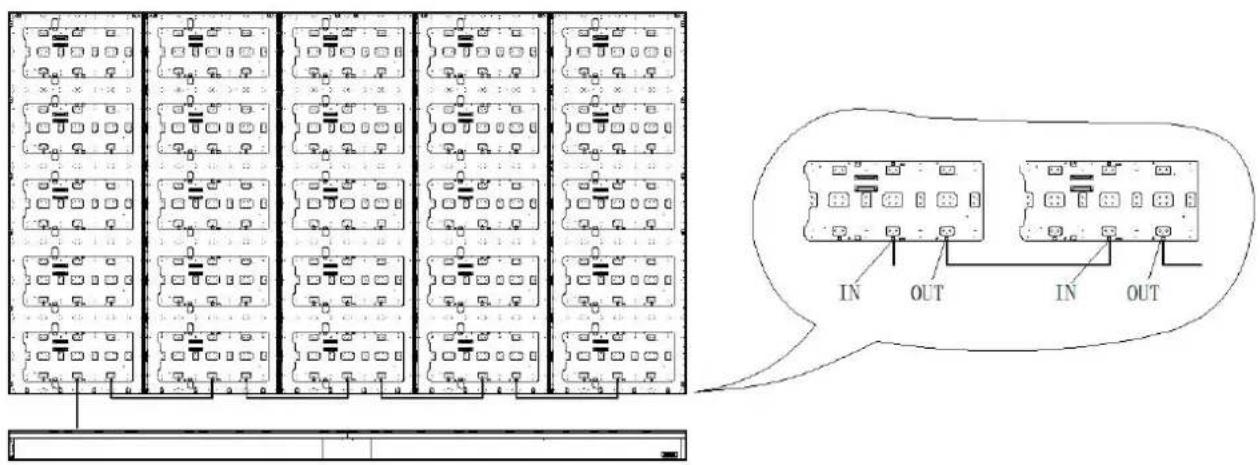
12). Attach the 2 pin connection from the soundbar to the cabinet A - IN connection. Then use the single provided 2 pin cables to connect from cabinet A - OUT to cabinet B - IN,
newline
Cabinet B - OUT to cabinet C - IN, cabinet C - OUT to cabinet D - IN, cabinet D - OUT to call E - IN.
For each cabinet, connect the red wire to the 24v connection point, the black wire to the ground point and the CAT5 connection point.
2 pin cable connection

Red and black cable connection
newline

natural_image
Technical diagram of a mechanical assembly with multiple panel layouts and a magnified inset showing a component (no text or symbols present)CAT5E cable connection
13). Use the provided hardware to attach the left and right upper borders across the cabinets.

Each cabinet frame is labeled with module position labels. Staff can quickly identify the module position through tags, as shown in the following figure.
newline


Explanation :
1) Number: represents the number of the same batch of all-in-one machines of the same model. For example, if there are 10 units of 150 in the same batch, this part is 1, 2, 3... 10.
2) Letter: represents the column number of the all-in-one machine, such as A, B, C, D for 120 inches.
3) Number : represents the number of modules within the same frame well as the module position. The number starts from the top left corner the front and is written in a Z-shape, as shown below. 120 inches: 32 modules/backboards; 150 inches: 40 modules/backboard; 180 inches: 48
modules/backboards.
| 1 | 2 | 3 | >4 |
| 5 | 6 | 7 | >8 |
| 9 | 10 | 11 | >12 |
| 13 | 14 | 15 | >16 |
| ...... |
newline
2. LED Module installation
1) Open the package of modules
2) The back of the module (IC surface) is labeled with module position identification, as shown in the following figure. The position of the module has been indicated in the label on the backboard mentioned above.

3) After installation, If the display is not flat or edges need adjusting, use the suction cup or vacuum tool to carefully remove the modules. Then adjust the magnetic standoffs with a small Philips screw driver to set the depth or height.
4) Attach the cover of the soundbar and then connect power cables to the rear of the soundbar.
newline
3. Function Introduction
3.1 Power On/Off
Panel key operation instructions:
- Short press: the power key: Start or shut down the DV.
- Long press the power key: Long press the 10S power button to restart the display.
Remote control operation instructions:
Click the power key on the remote control to enter the operation selection option. You can choose to enter the shutdown or standby mode.
Status Description:
Shutdown: The display panel is powered off.
Standby: Only cut off the signal.
Power light description:
Blue: Working state.
Red: In shutdown or standby mode
3.2 Product Connection
3.2.1 HDMI Input Connection

natural_image
Line drawing of a laptop connected to a monitor via cable (no text or symbols)Connection instructions:
- Connect the HDMI interface of the computer to the HDMI IN interface of the display using an HDMI cable;
- Use the panel key or remote control to switch channels and switch the display to the HDMI channel.
newline
3.2.2 USB Connecting

natural_image
Diagram showing a monitor setup with icons for keyboard, USB plug, and USB cable (no text or labels)Connection instructions:
Connect USB flash disk, USB mouse, and USB keyboards to the USB interface of the display;
After connection, the mouse and keyboard can be used;
You can view the contents of the USB disk in the file management software "Amaze" installed on the display.
3.2.3 Audio Output Connection

natural_image
Diagram showing a cord connecting two audio equipment units (no text or symbols present)Connection instructions:
- Connect the 3.5mm audio output port with the external audio devices such as power amplifiers and loudspeakers;
- The output volume can be adjusted through the panel volume button or remote control.
newline
3.3 System Introduction
3.3.1 Home Screen

- Video source: When the video source is connected to the all-in-one machine, you can click on the signal source and select the channel HDMI based on the actual connected signal source to display the video image.

newline
- Settings: Click the settings icon to enter the settings page, and adjust the corresponding items according to the needs, including network, display effects, sound, general, system, and other information viewing and settings.

- More applications: Enter more applications and select corresponding functions based on actual needs.

newline
Amaze: File manager, It can be used to browse system files and USB drive files and install apps.
Chromium: Google Browser.
VLC : Media player. It can be used to play audio and video files.
3.3.2 System Settings
1. Network settings
"Network settings": can connect to wireless networks, wired networks, Bluetooth, hotspots, and other connections.
Explanation: The Bluetooth of the all-in-one machine is a Bluetooth host and can only send files to the connected device in one direction.

2. Display Settings
"Display Settings": It is possible to choose different display modes and adjust brightness/contrast/saturation/manual or automatic color temperature
newline
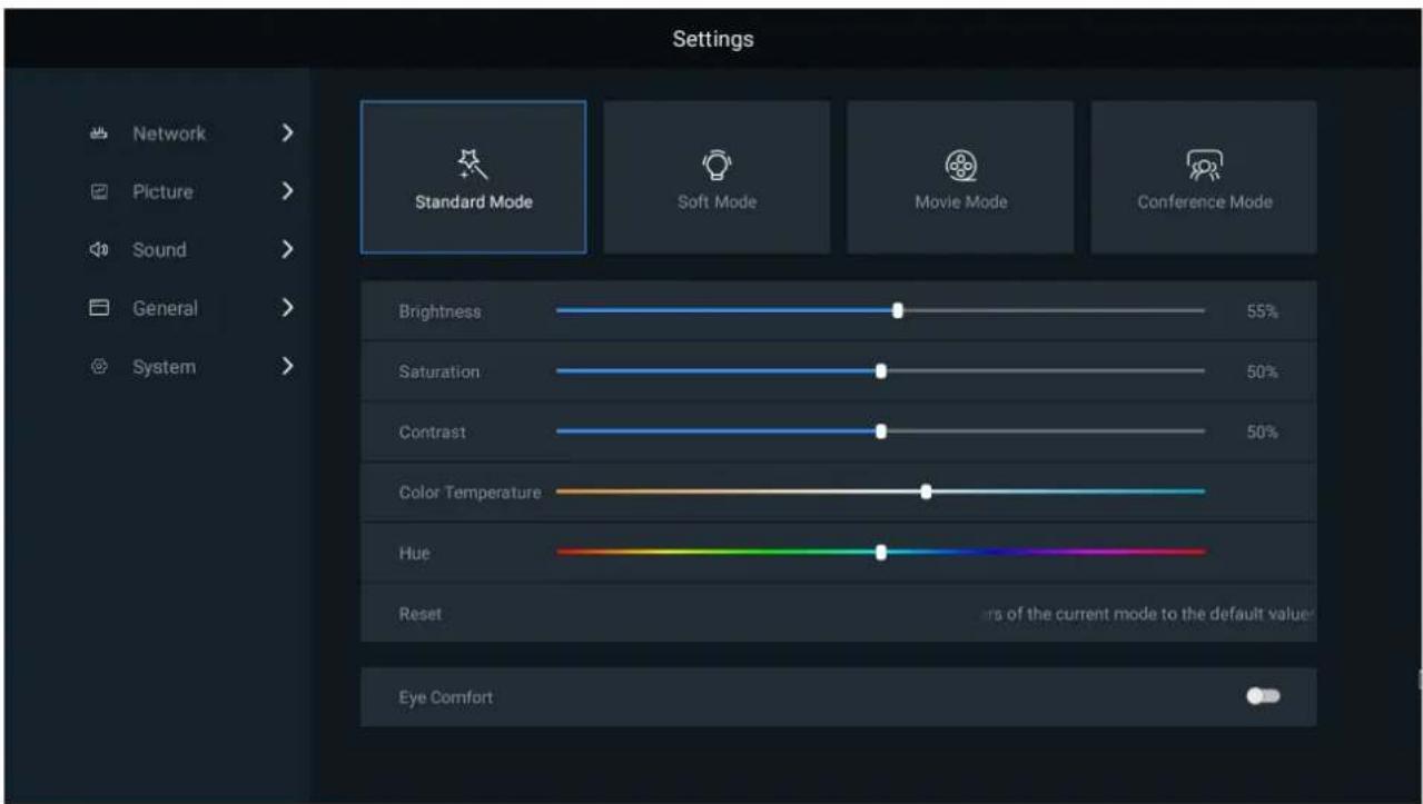
3. Sound settings
Sound Settings: Ability to adjust playback volume. When there is a different priority between the external speaker and the 3.5mm speaker, the 3.5mm audio interface output can be forcibly selected.

newline
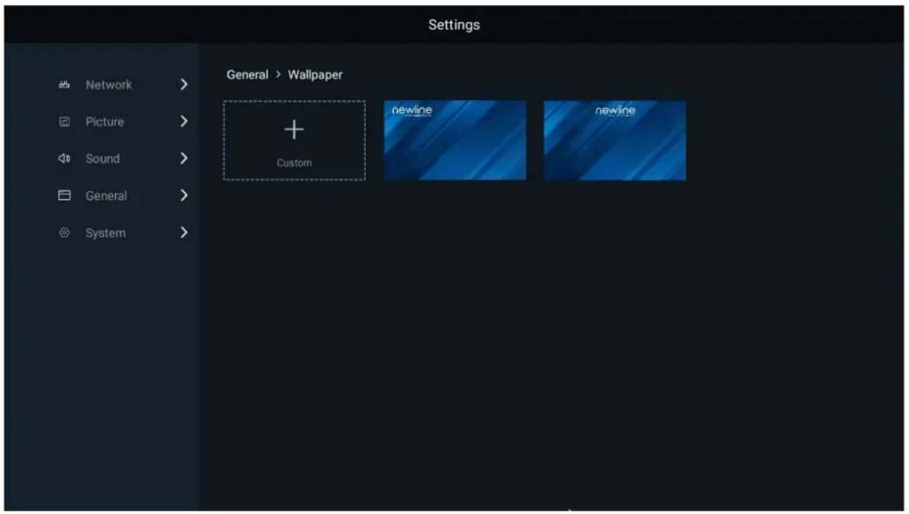
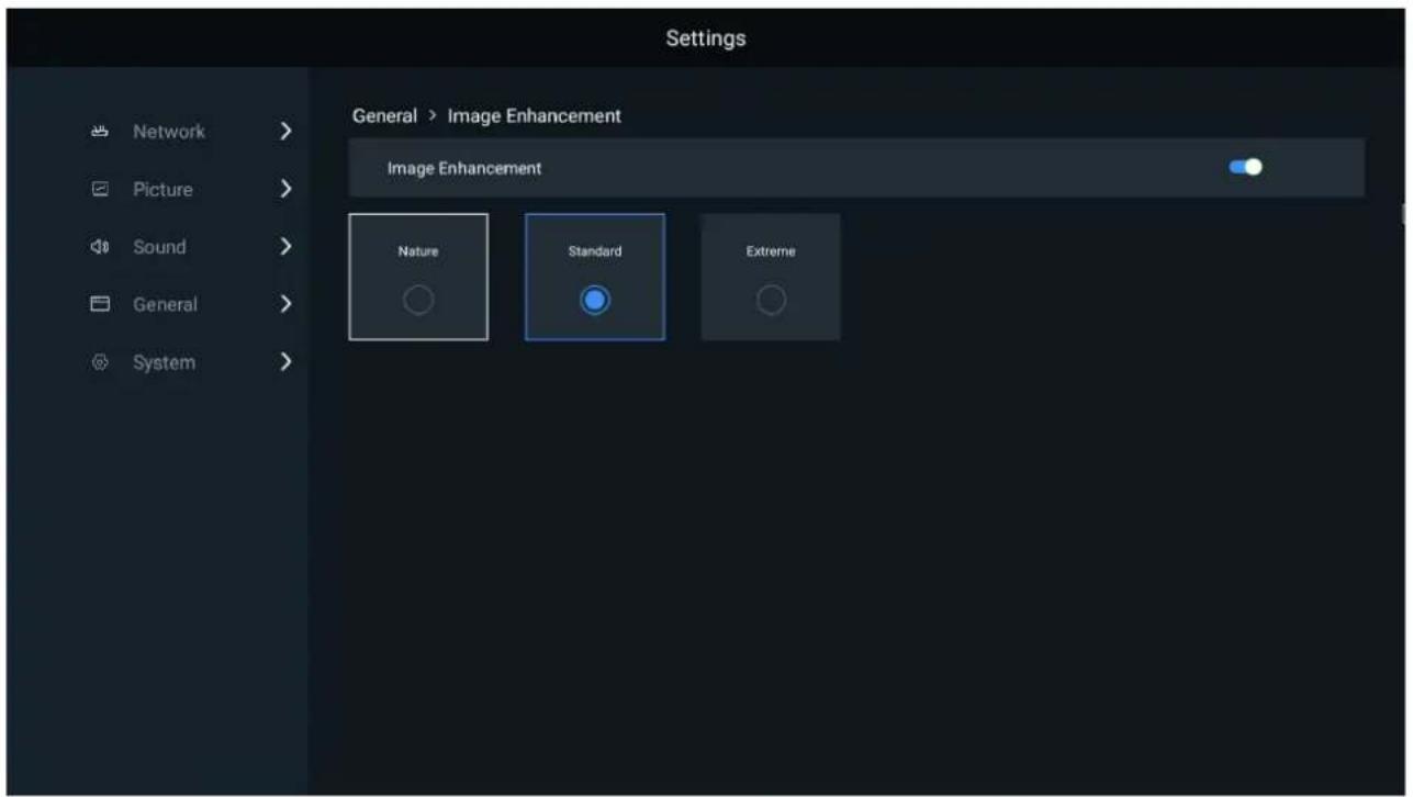
4. General settings
General settings can be used for program management, time and date, language, wallpaper, and other settings.
Explanation: The built-in program of the Android system cannot be uninstalled.


Settings
Network
Picture
Sound
General
System
General > Date & Time
Set Automatically
Date
Time
Time Zone

2023-11-16
3:35 PM >
GMT+08:00, China Standard Time
24-Hour Time
Date Format

2023-11-16
Settings
Network
Picture
Sound
General
System
General > Language & Keyboard
Language
Keyboard
English >
Android Keyboard (AOSP)
newline
newline
4. Maintenance
4.1 Precautions
- Before maintenance, the power supply must be shut off to prevent electric shock and injury, and avoid short circuit of the live parts of the PCB board against the metal frame.
- Please pay attention to protect the LED panel surface when using the front maintenance tools, and do not damage the module surface.
- Please pay attention to anti-static measures when using the front maintenance tools, and wear anti-static gloves to prevent static damage to LED.
- Pay attention to take out the module vertically to avoid damage and falling of LED lamp due to collision with edge of adjacent module.
4.2 LED Display Panel Maintenance
This product supports front LED panel maintenance. The tools required for front maintenance are vacuum front maintenance tools, as shown below:
- This product supports the front maintenance tool for the modules panel, as shown in the following figure.

| Serial | Items | Description |
| 1 | Suction cup rubber ring | Ensure good sealing |
newline
| 2 | Sucker | Seal between tool and LED panel |
| 3 | Power input interface | Connect the power cable |
| 4 | Handle | Handling |
| 5 | Turn on/off | Power on: “-”; Power off:“O” |
● The front maintenance process as follows:
Step 1: Turn off the power supply for the screen
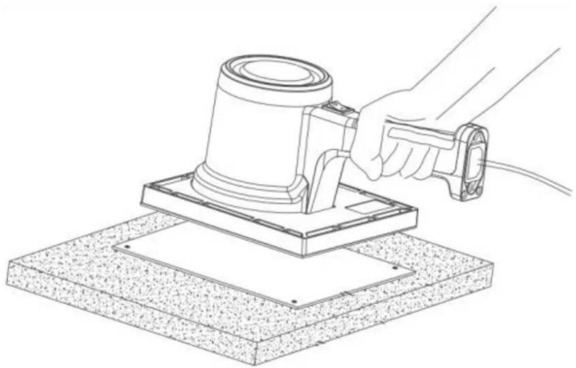
Step 2: Connect the AC power cable to the tool, align it with the power cable, and place it on the surface of the module. Press the on key. When the switch label is downward, the tool starts to pump air.

Step 3: After about 3-5 seconds of pumping air, the vacuum suction tightly adsorbs the module, and forcefully pulls the module out vertically. Hold the module with one hand to prevent it from falling off. Make sure that the module does not touch the adjacent lamp board when pulling out, so as to avoid collision and damage to the lamp bead.
newline

natural_image
Line drawing of a hand holding a device with a circular outline, showing internal components and wiring (no text or symbols)Step 4: After moving the module to the safe plane, press the switch key. At this time, the switch identifier O faces down. At this time, the adsorption force is removed and maintain modules, HUB board, receiving card.
natural_image
Line drawing of a hand using a power tool to press or install a mechanical component on a textured base (no text or symbols)newline
4.3 LED Display Panel Cleaning
During use, dust or other stains may adhere to the surface of the display. The cleaning steps of the product are as follows:
Step 1: Turn off the power of the display.
Step 2: Confirm the dirty place of the display
Step 3: Use the anti-static brush to wipe the dirty area and use the air gun to blow the clean place at the same time.
Notes:
- Do not use industrial grease cleaning agents or hard bristles during the cleaning process.
- Take anti-static measures to prevent static electricity from damaging the lamp beads.
- Pay attention to keeping the wiping direction consistent
4.4 Common Fault Analysis
| Fault | Analysis | Solution |
| Blank screen | Signal cable poor contact. | Check whether the signal cable connection or the signal cable are in good condition. |
| Power cable poor contact. | Check if the power cord connection is normal. | |
| No video signal output after connecting HDMI cable | Signal source mismatch | Check if the signal source channels match and match the signal source. |
| HDMI cable damaged | Check for poor contact and correct direction of the HDMI cable, and replace the HDMI cable. |
newline
5. Transportation and Delivery
5.1 Transportation
Packed products are suitable for air freight, shipment, and inland transport. It is not allowed to be loaded in an open cabin or compartment during long-distance transportation and shall not be stored in the open warehouse during midway transportation. It is not allowed to ship with inflammable, explosive, and corrosive articles in the same vehicle (or other means of transportation) during transportation, and it is necessary to protect the products from rain, snow or other liquid substances and mechanical damage.
5.2 Storage
During storage, the products shall be stored in the original packing box. The environmental temperature of the warehouse where the products are stored is 20 °C \~ 30 °C,
the relative humidity is <60%RH with no condensation. No hazardous gases, inflammable and explosive products and corrosive chemicals are allowed in the warehouse, and there is no strong mechanical vibration, impact, or magnetic field.
Note: Risk of damage to the device!
- Attention should be paid to extreme changes in temperature when transporting the box in cold weather. In this case, make sure there is no droplets (condensation) on or inside the device. If condensation on the device, Before turning on the device, contact customer service personnel to guide related operations, and ventilate and dry it. Do not power on without authorization.
- Keep the storage environment ventilated if the box is wet. After the box is dry, put it back in the original packing box for storage.
- Unpack and inspect the deliveries.
5.3 Unpacking
Please note the following when unpacking:
-
Do Not discard the original packaging material. Please keep the original packaging materials for use during new transportation.
-
Keep your documents in a safe place. This document is required for commissioning the device. It is also needed when presenting the equipment for debugging, and it is part of the equipment. and is part of the device.
newline
- Check the delivered device for any obvious damage during transportation.
- Verify that the goods shipped contains the complete device and accessories you ordered separately. If there is any discrepancy or damage during transportation, please contact customer service.
- The product should not be exposed to the installation site under construction for a long time after unpacking.
6. Warranty
- The warranty of the product is subject to the contract signed by both parties.
- Product failures caused by the following conditions are not covered by the warranty:
- Exceeding the effective warranty period and coverage; the warranty is inconsistent, altered, or lost.
- Any damage or changes of warranty caused by force majeure.
- Excessive product loss or malfunction due to unsuitable environment of use.
-
Other failures caused by reasons other than normal loss (normal loss refers to the loss of the product itself, parts, and software systems, etc. that occur under the premise of this document).
-
Our company shall not be responsible for any personal, property, or other losses caused by failure to comply with the contents of this document, including but not limited to guidance, steps, specifications, warnings, etc.
7. Recycling of Discarded Goods
Improper disposal of product waste may harm personal safety or damage the natural environment. It is recommended that consumers comply with local safety and environmental regulations and hand over the product to a local distributor or qualified waste recycling department for disposal when it is abandoned, in order to avoid environmental pollution and improve the material recycling rate.
- Newline DV All-in-one Direct View LED Display
- newline
- Catalogue
- Safety Instructions
- Important Warning
- Safety Code
- Warning Signs
- Documentation
- Copyright Notice
- Product Overview
- Product Appearance
- Product and Accessories
- Product Introduction
- Keys and Interfaces Introduction
- Remote Control Introduction
- Installation Guide
- Precautions
- Installation Dimensions
- Installation Steps
- DV Pedestal installation
- Cabinet Frame and sound bar installation
- Cabinet installation
- Explanation :
- LED Module installation
- Function Introduction
- Power On/Off
- Product Connection
- HDMI Input Connection
- Connection instructions:
- USB Connecting
- Audio Output Connection
- System Introduction
- Home Screen
- System Settings
- Network settings
- Display Settings
- Sound settings
- General settings
- Settings
- Maintenance
- Precautions
- LED Display Panel Maintenance
- LED Display Panel Cleaning
- Notes:
- Common Fault Analysis
- Transportation and Delivery
- Transportation
- Storage
- Unpacking
- Warranty
- Recycling of Discarded Goods
Brand : Newline
Model : DV-18023H
Category : LED Screen