
EVS7124D-V2 - Server Dahua Technology - Free user manual and instructions
Find the device manual for free EVS7124D-V2 Dahua Technology in PDF.


| Product Type | Embedded Video Storage Server |
| Model | EVS7124D-V2 |
| Brand | Dahua Technology |
| Operating System | Linux |
| HDD Bays | 24 (supports up to 24 hard drives) |
| RAID Levels | RAID 0, 1, 5, 6, 10, 50, 60, SRAID, JRAID |
| AI Functions | Face Detection, Face Recognition, People Counting, Vehicle Recognition, IVS, Video Metadata |
| Network Ports | Multiple Gigabit Ethernet ports (management and data) |
| Video Output | HDMI |
| Power Supply | Dual redundant power modules (estimated 800W each) |
| Dimensions (Approx.) | 2U rackmount: 88 x 482 x 600 mm (H x W x D) |
| Weight (Approx.) | 25 kg (without hard drives) |
| Operating Temperature | 0 °C to 45 °C (32 °F to 113 °F) |
| Operating Humidity | Allowed humidity conditions (check manual for details) |
| Certification | Class A product |
| Maintenance | Hot-swappable HDDs, firmware upgrade via web/PCAPP |
| Safety Features | Protective earthing, surge protection, password protection, account lock |
| Spare Parts / Repairability | Hard drives, power modules, AI modules (if applicable); professional repair required |
| General Information | Dual-controller design, supports PCAPP and web interface, network storage (NFS, SMB, FTP) |
Frequently Asked Questions - EVS7124D-V2 Dahua Technology
User questions about EVS7124D-V2 Dahua Technology
0 question about this device. Answer the ones you know or ask your own.
Ask a new question about this device
Download the instructions for your Server in PDF format for free! Find your manual EVS7124D-V2 - Dahua Technology and take your electronic device back in hand. On this page are published all the documents necessary for the use of your device. EVS7124D-V2 by Dahua Technology.
USER MANUAL EVS7124D-V2 Dahua Technology
Embedded Video Storage
User's Manual

natural_image
Abstract geometric composition with gray and red color blocks (no text or symbols)Foreword
General
This manual introduces the functions and operations of the embedded video storage server (hereinafter referred to as "the Device"). Read carefully before using the device, and keep the manual safe for future reference.
Models
EVS7124D; EVS7148D

In the name EVS71XXD, XX refers to HDD number (24, or 48); D indicates that the Device is dual-controller type.
Safety Instructions
The following signal words might appear in the manual.
| Signal Words Meaning | |
 DANGER DANGER | Indicates a high potential hazard which, if not avoided, will result in death or serious injury. |
 WARNING WARNING | Indicates a medium or low potential hazard which, if not avoided, could result in slight or moderate injury. |
 CAUTION CAUTION | Indicates a potential risk which, if not avoided, could result in property damage, data loss, reductions in performance, or unpredictable results. |
 TIPS TIPS | Provides methods to help you solve a problem or save time. |
 NOTE NOTE | Provides additional information as a supplement to the text. |
Privacy Protection Notice
As the device user or data controller, you might collect the personal data of others such as their face, fingerprints, and license plate number. You need to be in compliance with your local privacy protection laws and regulations to protect the legitimate rights and interests of other people by implementing measures which include but are not limited: Providing clear and visible identification to inform people of the existence of the surveillance area and provide required contact information.
Revision History
| Version Revision Content Release Time | ||
| V2.0.1 | Added virtual IP. | May 2022 |
| V2.0.0 | Added the functions such as one-click disarming, voice talk, and SSD health detection. | May 2022 |
| V1.0.0 | First release. | September 2020 |
About the Manual
- The manual is for reference only. Slight differences might be found between the manual and the product.
- We are not liable for losses incurred due to operating the product in ways that are not in compliance with the manual.
- The manual will be updated according to the latest laws and regulations of related jurisdictions. For detailed information, see the paper user's manual, use our CD-ROM, scan the QR code or visit our official website. The manual is for reference only. Slight differences might be found between the electronic version and the paper version.
- All designs and software are subject to change without prior written notice. Product updates might result in some differences appearing between the actual product and the manual. Please contact customer service for the latest program and supplementary documentation.
- There might be errors in the print or deviations in the description of the functions, operations and technical data. If there is any doubt or dispute, we reserve the right of final explanation.
- Upgrade the reader software or try other mainstream reader software if the manual (in PDF format) cannot be opened.
- All trademarks, registered trademarks and company names in the manual are properties of their respective owners.
- Please visit our website, contact the supplier or customer service if any problems occur while using the Device.
- If there is any uncertainty or controversy, we reserve the right of final explanation.
Important Safeguards and Warnings
This section introduces content covering the proper handling of the device, hazard prevention, and prevention of property damage. Read carefully before using the device, and comply with the guidelines when using it.
Operation Requirements

WARNING
- This is a class A product. In a domestic environment this may cause radio interference in which case you may be required to take adequate measures.
- The device is heavy and needs to be carried by several persons together to avoid personal injuries.

- Check whether the power supply is correct before use.
- Do not unplug the power cord on the side of the device while the adapter is powered on.
- Operate the device within the rated range of power input and output.
- Use the device under allowed humidity and temperature conditions.
- Do not drip or splash liquid onto the device, make sure that there is no object filled with liquid on the device to prevent liquid from flowing into it.
- Do not disassemble the Device.
- The device can only be used with batteries possessing internal protection.
- Your configurations will be lost after performing a factory reset. Please be advised.
- Do not restart, shut down or disconnect the power to the device during an update.
- Make sure the update file is correct because an incorrect file can result in a device error occurring.
- Do not frequently turn on/off the device. Otherwise, the product life might be shortened.
- Back up important data on a regular basis when using the device.
- Operating temperature: 0 °C to 45 °C (32 °F to 113 °F).
- Salt pray in the operating environment of the device might corrode its electronic components and cables. To ensure the normal operation of the device and prolong its service life, use the device in an indoor environment that is 3 kilometers away from the sea.
Installation Requirements

WARNING
- Strictly comply with the local electric safety code and standards. Make sure the ambient voltage is stable and meets the power supply requirements of the device.
- Do not expose the battery to environments with extremely low air pressure, or extremely high or low temperatures. Also, it is strictly prohibited for the battery to be thrown into a fire or furnace and to cut or put mechanical pressure on the battery. This is to avoid the risk of fire and explosion.
- Use the standard power adapter or cabinet power supply. We will assume no responsibility for any injuries or damages caused by the use of a nonstandard power adapter.

- Do not place the device in a place exposed to sunlight or near heat sources.
- Keep the device away from dampness, dust, and soot.
- Put the device in a well-ventilated place, and do not block its ventilation.
• Install the server on a stable surface to prevent it from falling. - The device is a class I electrical appliance. Make sure that the power supply of the device is connected to a power socket with protective earthing.
- Use power cords that conform to your local requirements and rated specifications.
- Before connecting the power supply, make sure the input voltage matches the server power requirement.
- When installing the device, make sure that the power plug and appliance coupler can be easily reached to cut off power.
• Install the server in an area that only professionals can access. - Extra protection is necessary for the device casing to reduce the transient voltage to the defined range.
- If you did not push the HDD box to the bottom, then do not close the handle to avoid damage to the HDD slot.
• Install the device near a power socket for emergency disconnect. - It is prohibited for non-professionals and unauthorized personnel to open the device casing.
- Affix the device securely to the building before use.
Maintenance Requirements

WARNING
- Make sure to use the same model when replacing the battery to avoid fire or explosion. Dispose the battery strictly according to the instructions on it.
● Power off the device before maintenance.

- AI module does not support hot plug. If you need to install or replace the AI module, unplug the device power cord first. Otherwise, it will lead to file damage on the AI module.
- The device casing provides protection for internal components. Use a screwdriver to loosen the screws before detaching the casing. Make sure to put the casing back on and secure it in its original place before powering on and using the device.
- It is prohibited for non-professionals and unauthorized personnel to open the device casing.
- The appliance coupler is a disconnection device. Keep it at a convenient angle when using it. Before repairing or performing maintenance on the device, first disconnect the appliance coupler.
Transportation Requirements

Transport the device under allowed humidity and temperature conditions.
Storage Requirements

Store the device under allowed humidity and temperature conditions.
Table of Contents
Foreword....I
Important Safeguards and Warnings....III
1 Overview....1
1.1 Introduction....1
1.2 Front Panel....1
1.3 Rear Panel 3
1.4 Menu Items....4
2 Installation and Powering Up 5
2.1 Installing HDD 5
2.2 Powering Up 7
2.2.1 Preparation....7
2.2.2 Powering up the Device 7
3 Initial Settings 8
3.1 Initializing the Device....8
3.2 Quick Settings ....11
3.3 Login....13
3.3.1 Logging in to PCAPP Client....13
3.3.2 Logging in to Web Interface ....17
3.4 Configuring Remote Device....18
3.4.1 Initializing Remote Device....18
3.4.2 Adding Remote Device....23
4 AI Operations....34
4.1 Face Detection ....34
4.1.1 Enabling AI Plan 34
4.1.2 Configuring Face Detection....35
4.1.3 Live View of Face Detection 37
4.1.4 Face Search....40
4.2 Face Recognition....44
4.2.1 Enabling AI Plan 44
4.2.2 Configuring Face Recognition 44
4.2.3 Live View of Face Recognition....45
4.2.4 Face Search....47
4.3 People Counting....49
4.3.1 Enabling AI Plan 49
4.3.2 People Counting 49
4.3.3 Queuing Detection....50
4.3.4 Live View ....52
4.4 Video Metadata....52
4.4.1 Enabling AI Plan 53
4.4.2 Configuring Video Metadata ....53
4.4.3 Live View of Video Metadata....54
4.4.4 AI Search....57
4.5 IVS....64
4.5.1 Enabling AI Plan ....64
4.5.2 Configuring IVS....64
4.5.3 Live View of IVS....69
4.5.4 IVS Search 72
4.6 Vehicle Recognition....73
4.6.1 Enabling AI Plan ....74
4.6.2 Setting Vehicle Recognition....74
4.6.3 Live View of Vehicle Recognition ....74
4.6.4 Searching for Detection Information....77
4.7 Crowd Distribution Map....77
4.7.1 Enabling AI Plan ....77
4.7.2 Configuring Crowd Distribution Map ....77
4.7.3 Live View of Crowd Distribution....79
4.8 Call Alarm....80
4.8.1 Enabling AI Plan ....80
4.8.2 Configuring Call Alarm ....80
4.8.3 Live View of Call Alarm....82
4.9 Smoking Alarm 82
4.9.1 Configuring Smoking Alarm....82
4.9.2 Live View of Smoking Alarm 83
5 General Operations 84
5.1 Live and Monitor....84
5.1.1 View Management ....85
5.1.2 Resources Pool....101
5.1.3 PTZ....102
5.2 Recorded Files 110
5.2.1 Playing Back Recorded Video....111
5.2.2 Clipping Recorded Video 115
5.2.3 Playing Back Snapshots....116
5.2.4 Exporting File 118
5.2.5 Video Tag....121
5.2.6 Locking Files 121
5.3 Alarm List 122
5.4 System Information....123
5.5 Background Task....123
5.6 Buzzer....124
6 System Configuration 125
6.1 Configuration Page 125
6.2 Device Management ....125
6.2.1 Viewing Device Information 126
6.2.2 Remote Devices....127
6.3 Network Management....141
6.3.1 Basic Network....141
6.3.2 Network Apps 148
6.4 Event Management....161
6.4.1 Alarm Actions....161
6.4.2 Local Device....167
6.4.3 Remote Device....174
6.5 Storage Management....180
6.5.1 Local Hard Disk 180
6.5.2 RAID 183
6.5.3 Network Hard Disk 190
6.5.4 FTP/SFTP 192
6.6 Video Recording 194
6.6.1 Storage Mode....194
6.6.2 Recording Schedule 199
6.6.3 Basic 201
6.6.4 Record Transfer 202
6.7 Security Strategy 203
6.7.1 HTTPS 204
6.7.2 Configuring Access Permission 208
6.7.3 Safety Protection....210
6.7.4 Enabling System Service Manually 211
6.7.5 Configuring Firewall 212
6.7.6 Configuring Time Synchronization Permission 213
6.8 Account Management 214
6.8.1 User Group 214
6.8.2 Device User 217
6.8.3 Password Maintenance....219
6.8.4 ONVIF 224
6.9 System Configuration....227
6.9.1 Setting System Parameters....227
6.9.2 System Time....228
6.9.3 Schedule....230
6.10 Network Storage 231
6.10.1 Creating Storage Pool 232
6.10.2 Managing Share Account 233
6.10.3 Configuring Share Folder 234
6.10.4 Configuring Share Control 236
6.10.5 Configuring FTP Parameters 237
7 System Management 238
7.1 File Management 238
7.1.1 Video Tag Management....238
7.1.2 FILE LOCKED....238
7.1.3 Watermark Verification....239
7.2 Task Management....240
7.3 Backup....243
7.4 AI Report....245
7.4.1 In-area People Counting Report 245
7.4.2 Queue People Counting Report....247
8 System Maintenance 249
8.1 Overview 249
8.2 System Information....250
8.2.1 Viewing Device Information 250
8.2.2 Viewing Legal Information 250
8.3 System Resources 250
8.4 Logs 251
8.5 Intelligent Diagnosis....253
8.5.1 Run Log....253
8.5.2 One-click Export 253
8.5.3 One-click Diagnosis 254
8.6 Network Care 254
8.6.1 Online User 254
8.6.2 Packet Capture 255
8.7 Device Maintenance 256
8.7.1 Upgrading Device....256
8.7.2 Default 258
8.7.3 Automatic Maintenance....258
8.7.4 IMP/EXP 259
8.8 Disk Maintenance 259
8.8.1 S.M.A.R.T Detection....260
8.8.2 Health Monitoring 260
8.8.3 SSD Health Detection....260
8.8.4 Firmware Update 260
9 PCAPP Introduction 262
9.1 Page Description 262
9.2 History Record....262
9.3 Viewing Downloads 263
9.4 Configuring PCAPP 263
9.5 Viewing Version Details....265
10 Log Out, Reboot, Shut Down, Lock 266
Appendix 1 Particulate and Gaseous Contamination Specifications .... 268
Appendix 1.1 Particulate Contamination Specifications....268
Appendix 1.2 Gaseous Contamination Specifications....268
Appendix 2 RAID 270
Appendix 3 Glossary 272
Appendix 4 Cybersecurity Recommendations....274
1 Overview
1.1 Introduction
The Device is designed for the management, storage and application of high-definition video data. It uses Linux operation system and professional customized hardware platform, and it is configured with multiple Hard Disk Drive (HDD) management system, front-end HD device management system, HD video analysis system and large capacity video storage system.
It adopts high-traffic data network transmission & forward technology and multi-channel video decoding & display technology, and realizes intelligent management, secure storage, fast forwarding and HD decoding of large capacity and multi-channel HD video data.
The Device provides standard network file sharing service and offers integrated network storage solution. It provides centralized storage solutions with large capacity, high scalability and high security for all kinds of video monitoring systems.
1.2 Front Panel
Figure 1-1 EVS7124D
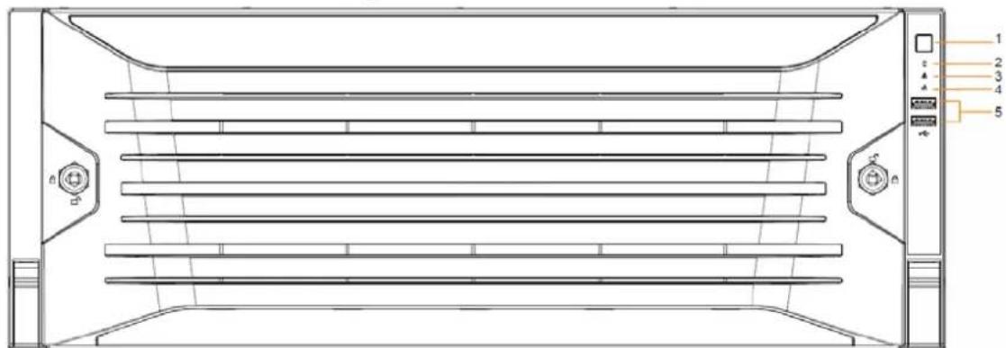
Figure 1-2 EVS7148D
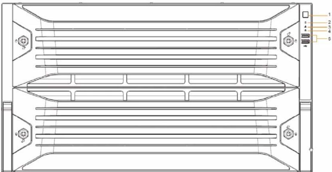
Table 1-1 Front panel description
| No. Name | Description | |
| 1 Power button | Turns on or off the Device.If the Device is off, press this button to turn the Device on.To turn off the Device, press and hold this button for 5 seconds. | |
| 2 | HDD status indicator | The light is off when the HDD is in normal operation.The light is solid red if no HDD, HDD error or insufficient HDD space. |
| 3 | Alarm status indicator | The light is off when the Device is running properly.The light is solid red when the power, temperature or fan is abnormal. |
| 4 | Network status indicator | The light is solid red if there is a network failure, IP conflict or MAC conflict. |
| 5 | USB ports | Connect to external USB devices, such as flash drive. |
1.3 Rear Panel
Figure 1-3 EVS7124D
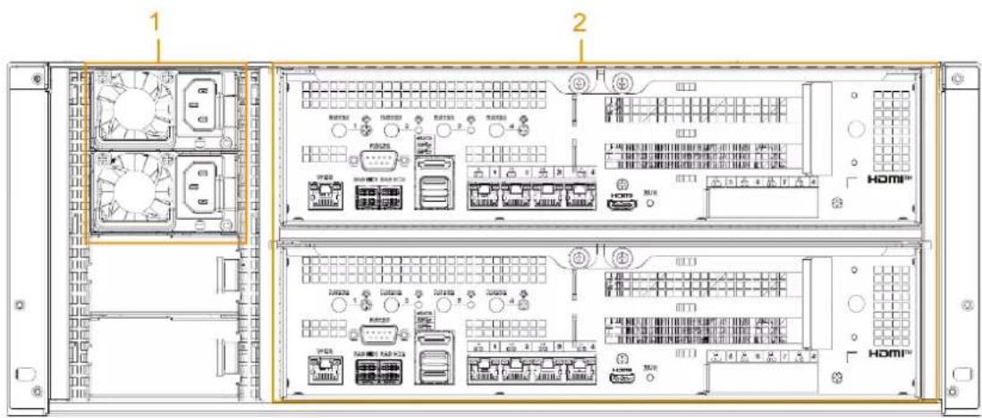
Figure 1-4 EVS7148D
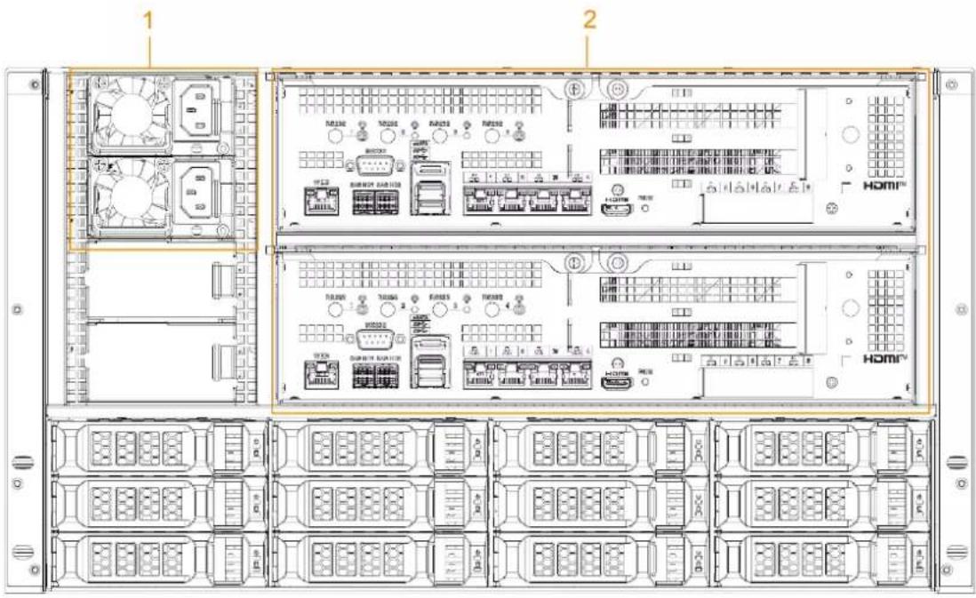
Table 1-2 Rear panel ports
| No. Port | Description | |
| 1 | Power module | Connects to AC power supply. Contains fans for case cooling. |
| 2 | RS-232 | Used to debug general serial ports, configure IP address and transmit transparent serial data. |
| WEB | Gigabit management port. Can be used as data port. | |
| SAS HD | Connects to the expansion cabinet.The SAS HD ports might differ depending on the device you are using.We recommend using SAS HD2. | |
| eSATA | Connects to external storage devices. | |
| USB 3.0 | Connects the mouse or USB storage devices. | |
| EX-1–EX-4/1–4 | Gigabit Ethernet ports. Used to transfer data. | |
| HDMI | Outputs high definition video data and multi-channel audio data to external displays. | |
| PCI-E | High-speed expansion port, connects to components with X4 or X8 plug. |
1.4 Menu Items
This section introduces the icons and buttons you will frequently use when using the Device.
Table 1-3 Icons and buttons
| Icon/Button Description | |
| Default | Restore default configuration. |
| Refresh | Get the latest configuration information. |
| Save | Save the modified configuration. |
| OK | |
| Cancel | Cancel the modified configuration and close the window. |
| Checkbox. You can select multiple configuration items at the same time.☑: Selected. | |
| Radio button. You can select a configuration item. :Selected. | |
| Drop-down list. Click this icon to display the drop-down menu. | |
2 Installation and Powering Up
2.1 Installing HDD
The HDD is not installed by default on factory delivery. You need to install it by yourself.

WARNING
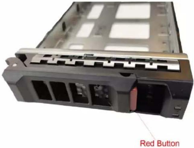
Some devices are heavy and should be carried jointly by several persons to avoid injury. Step 1 Press the red button on the disk tray to unlock the handle.
Figure 2-1 Open the handle
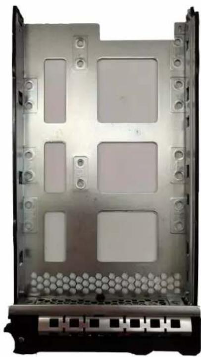
Step 2 Pull out the empty disk tray.
Figure 2-2 Disk tray
natural_image
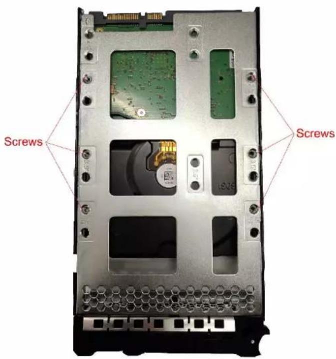
Metallic computer case with multiple rectangular panels and mounting holes, mounted on a black rack (no text or symbols visible)Step 3 Put the disk into the disk tray and fasten the screws at the bottom of the tray.
Figure 2-3 Fasten the screws
Step 4 Insert the disk tray into the HDD slot, push it to the bottom and lock the handle.

To avoid any damage to the slot, do not lock the handle until the disk tray has been pushed to the bottom.
2.2 Powering Up
2.2.1 Preparation
Properly connect the cables before powering up the Device and check against the following items:
● Make sure that all power lines are connected correctly.
- Check whether the supplied power voltage complies with device requirements.
- Check whether the network cables and SAS cables are connected correctly.
2.2.2 Powering up the Device
Press the power button on the front panel, and then check whether the indicators are normally displayed.
- When the indicators are normal, the Device is powered up successfully.
- If the indicators are abnormal, solve the problems and then power up the Device again.
3 Initial Settings
When using EVS for the first time, initialize the Device, and set basic information and functions first.
3.1 Initializing the Device
If it is your first time to use the Device after purchasing or after restoring factory defaults, set a login password of admin (system default user). At the same time, you can set proper password protection method.

This section uses web remote initialization for example.
Step 1 Open the browser, enter IP address, and then press the Enter key.

The default IP addresses of network port 1 to network port n in slot 1 are 192.168.1.108 to 192.168.n.108. Enter the corresponding IP address of the actually connected network port.
Step 2 On the Language Set page, select a country or region, a language, and a language standard. Click Next. The language setting step is only available on the local interface of the Device.
Figure 3-1 Time setting
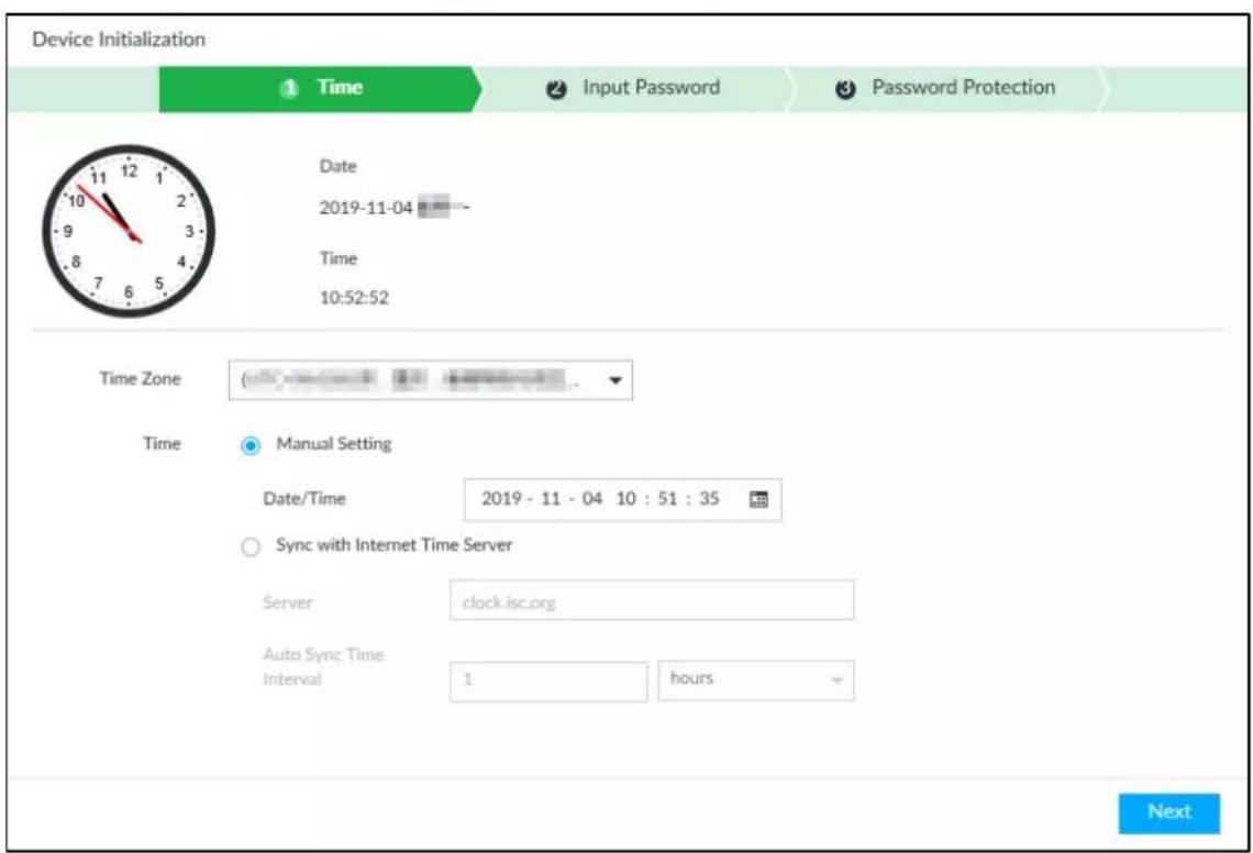
Step 3 On the Time page, set time parameters.
Table 3-1 Time parameters description
| Parameters Description |
| Time Zone The time zone of the Device. |
| Parameters Description | |
| Time | Set system date and time manually or by synchronizing with NTP server time.Manual setting: Select date and time from the calendar.Sync with Internet Time Server: Select Sync with Internet Time Server, enter NTP server IP address or domain, and then set the automatic synchronization interval. Device time will synchronize with the server time after Sync with Internet Time Server is set. Device time will synchronize with the server time after Sync with Internet Time Server is set. |
Step 4 Click Next.
Figure 3-2 Set password
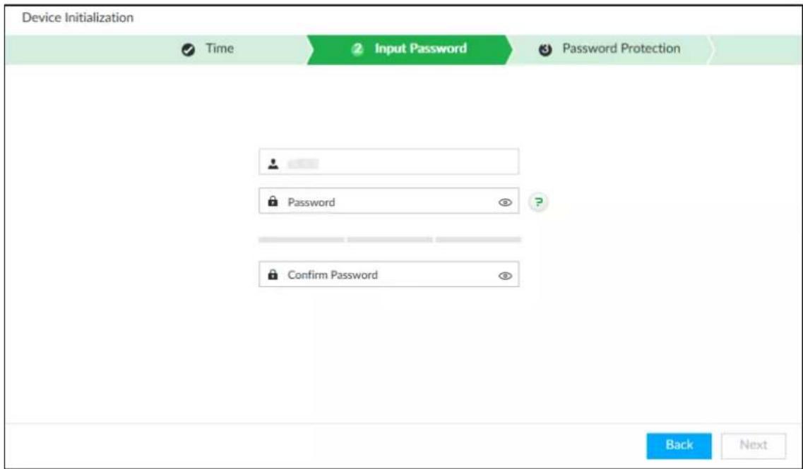
Step 5 Set admin login password.
Table 3-2 Description of password parameters
| Parameters Description | |
| Username | The default username is admin. |
| Password | Set admin login password, and confirm the password.The password must consist of 8–32 non-blank characters and contain at least two types of the following characters: uppercase, lowercase, number, and special character (excluding ' "; : &). Enter a strong password according to the password strength indication. |
| Confirm Password | |
Step 6 Click Next.
Figure 3-3 Password protection
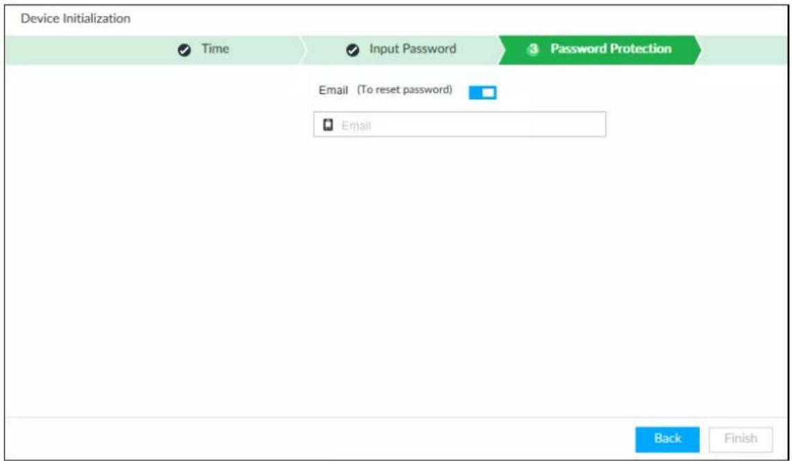
Step 7 Set password protection information.
You can use the email you set here to reset admin password. See "6.8.3.2 Resetting Password" for detailed information.
1) Click □ to enable email.
2) Enter an email address in the Email box.
Step 8 Click Finish to complete device initialization.
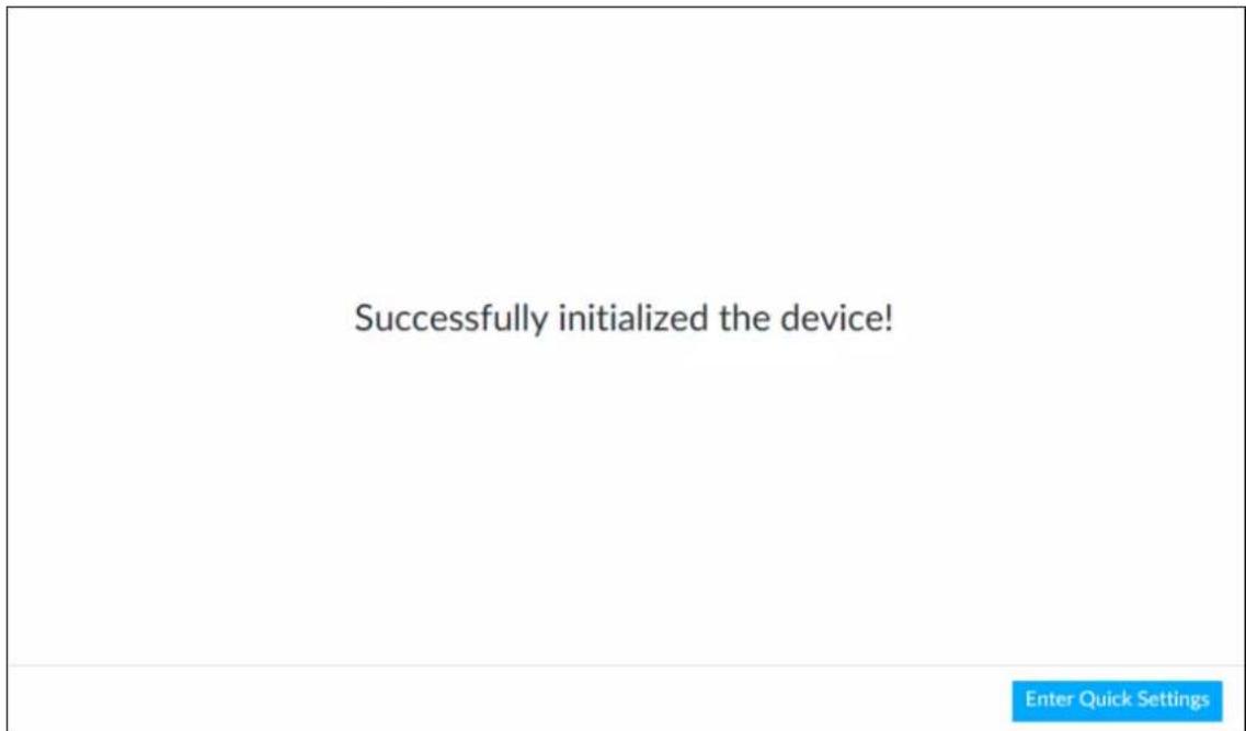
The device initialization success page is displayed. Click Enter quick settings to go to the quick setting page, and then set device basic information. See "3.2 Quick Settings" for details.
Figure 3-4 Initialization completed
3.2 Quick Settings
After initializing the Device, the system goes to quick settings page. You can quickly configure system time, and network settings.

Make sure that at least one Ethernet port has connected to the network before you set IP address.
Step 1 On the completion page of initialization, click Enter Quick Setting.
Figure 3-5 IP setting
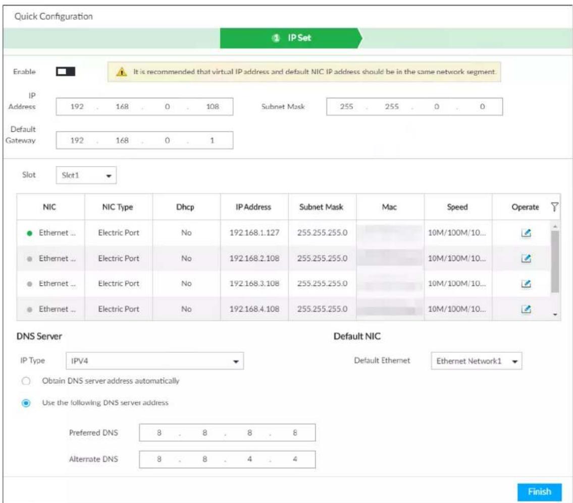
Step 2 Click ☐ to enable the virtual IP address, and then set the virtual IP address, subnet mask and default gateway.
The main board and standby board have their respective physical IP. After setting the virtual IP, despite the switch between the main and standby boards, you can always log in to the web interface with the virtual IP.

The default virtual IP address is 192.168.0.108. We recommend you set the virtual IP address and the IP address of the default NIC on the same network segment.
Step 3 Select a slot from Slot1 and Slot2 and then set the NICs in each slot.
1) Click of the corresponding NIC.
Figure 3-6 Edit Ethernet network
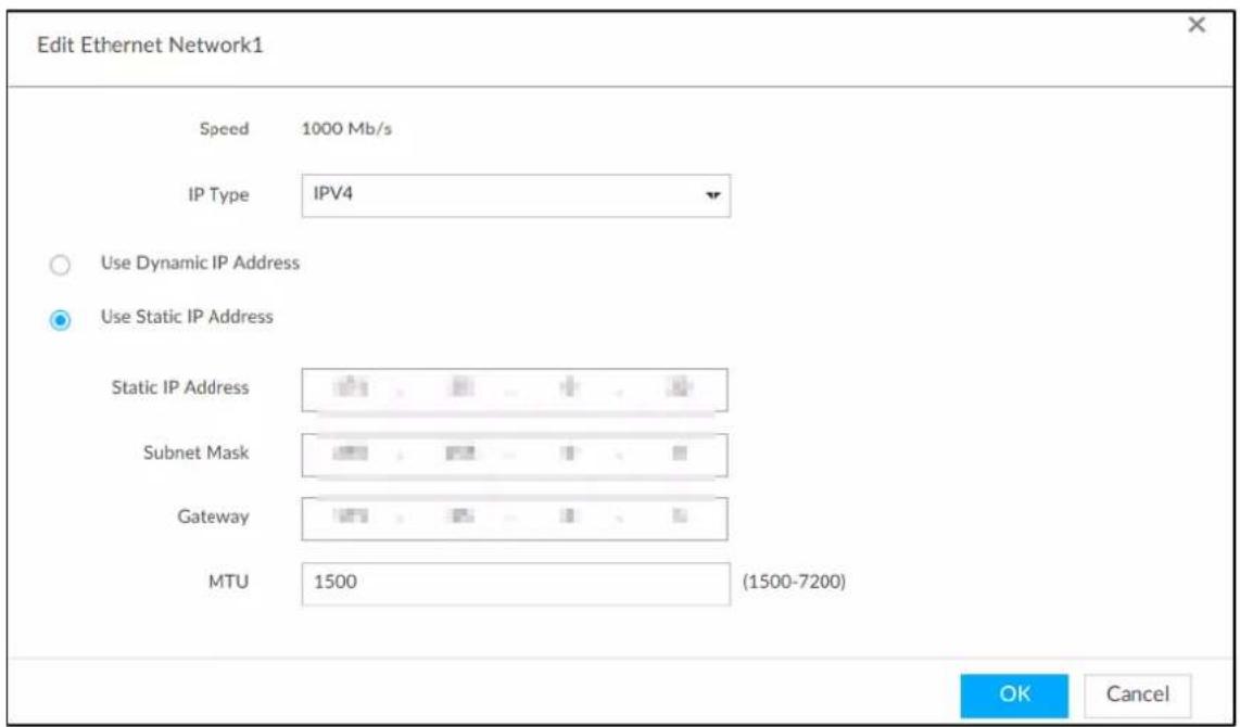
2) Set parameters.
Table 3-3 TCP/IP parameters description
| Parameters Description | |
| Speed | Current NIC max network transmission speed. |
| IP Type | Select IPv4 or IPv6. |
| Use dynamic IP address | When there is a DHCP server on the network, check Use Dynamic IP Address, system can allocate a dynamic IP address to the Device. There is no need to set IP address manually. |
| Use static IP address | Check Use Static IP Address, and then set static IP address, subnet mask and gateway to set a static IP address for the Device. |
| MTU | Set NIC MTU value. The default setup is 1500 Byte.We recommend you check the MTU value of the gateway first and then set the Device MTU value equal to or smaller than the gateway value. Reduce the packets slightly and enhance network transmission efficiency. Changing MTU value might result in NIC reboot, network offline and affect current running operation. Please be careful! Changing MTU value might result in NIC reboot, network offline and affect current running operation. Please be careful! |
3) Click OK.
Device goes back to IP Set page.
Step 4 Set DNS server information.
You can select to get DNS server manually or enter DNS server information.

This step is compulsive if you want to use domain service.
1) Select an IP type for DNS server. You can select IPv4 or IPv6.
2) Select the way of setting DNS IP address.
◇ Select Obtain DNS server address automatically, and then the Device can automatically get the DNS server IP address on the network.
◇ Select Use the following DNS server address, and then enter the preferred DNS IP address and the alternate DNS IP address.
Step 5 Set default NIC.
Select default NIC from the drop-down list.

Make sure that the default NIC is online.
Step 6 Click Next to save settings.
3.3 Login
You can access and manage the Device remotely by using the PCAPP (PC client), or the web interface.
3.3.1 Logging in to PCAPP Client
Log in to the PCAPP for system configuration and operation.
Step 1 Download PCAPP.
1) Open the browser, enter IP address, and press Enter.
Figure 3-7 Web login
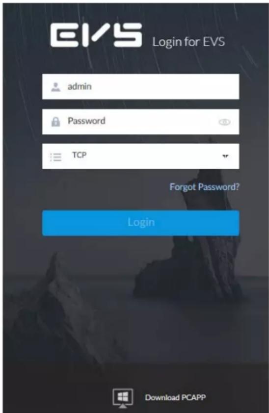
2) Click Download PCAPP to download PCAPP installation package.
Step 2 Install PCAPP.
1) Double-click the PCAPP installation package.
The installation page is displayed.
Figure 3-8 Installation page

2) Select a language of the PCAPP.
3) Click EULA, read through the content, and then select the checkbox of I Agree EULA.
4) (Optional) Click Custom and then select an installation path and create shortcut.
Figure 3-9 Custom installation
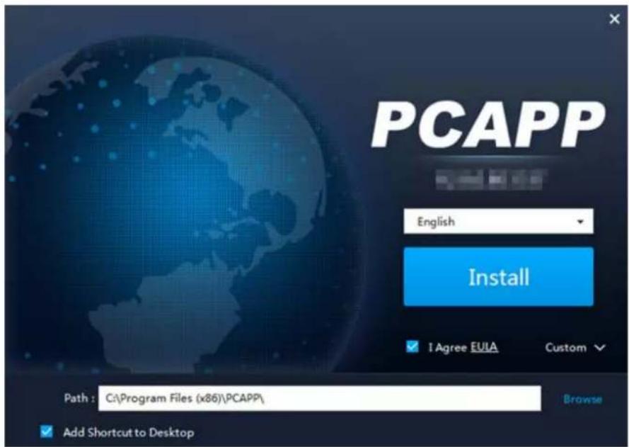
5) Click Install.
On completion, the completion page is displayed.
Figure 3-10 The installation is completed

Step 3 Log in to PCAPP.
1) There are two ways to enter PCAPP.
- On the installation completion page, click Run.
- Double-click the shortcut icon on the PC desktop.

- When PC theme is not Aero, the system will remind you to switch the theme. See Figure 3-11. To ensure video smoothness, switch your PC to Areo theme. For details, see "9.4 Configuring PCAPP". - System display PCAPP at full-screen by default. Click ▼ to display the task column. See Figure 3-12.
Figure 3-11 Prompt
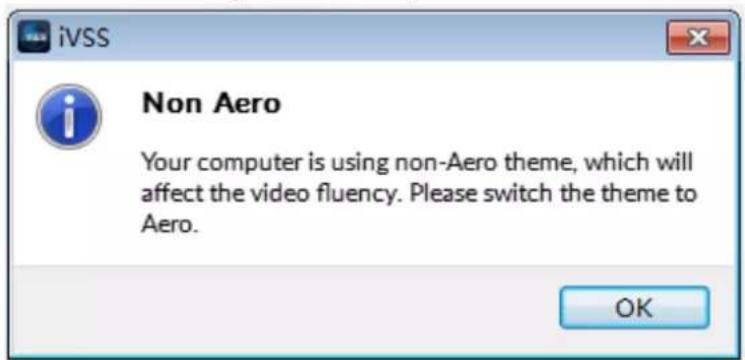
Figure 3-12 Initial page

2) Enter device IP address, and then press Enter or click →.
Figure 3-13 Login
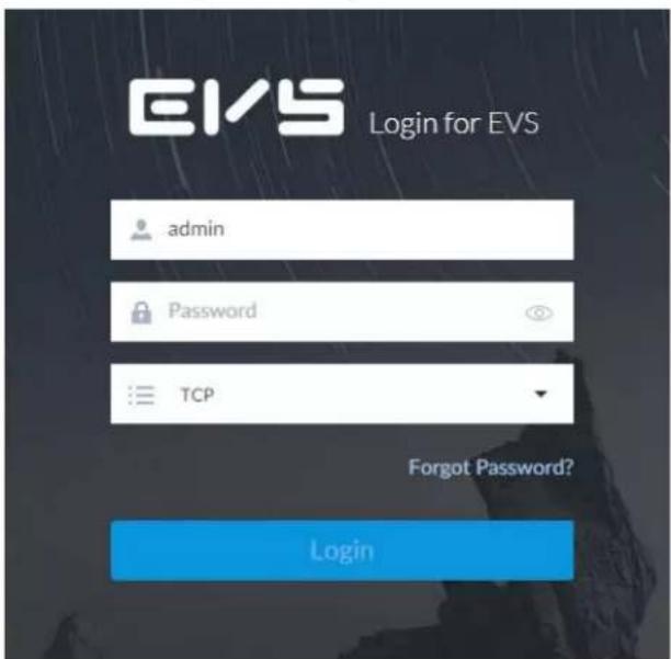
3) Enter device username and password.

- Click Login. For your device safety, change the admin password regularly and keep it well.
- In case you forgot password, click Forgot password to reset. See "6.8.3.2 Resetting Password" for detailed information.
4) Select the login type among TCP, UDP and Multicast. Keep it TCP if you have no special requirement for TCP or UDP.
5) Click Login.
Figure 3-14 Home page
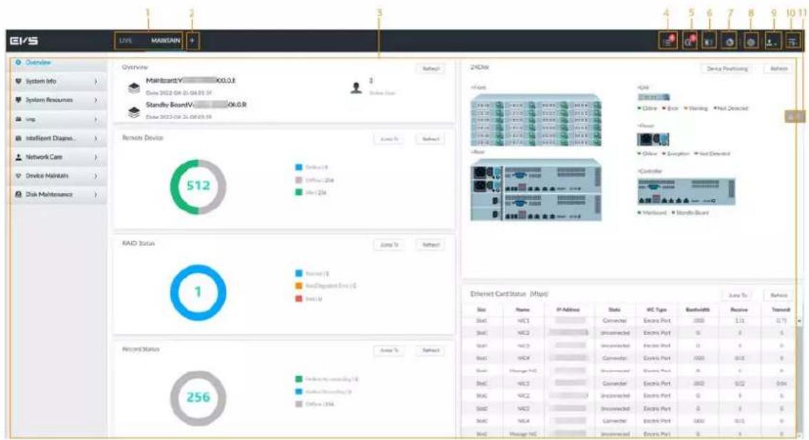
Table 3-4 Home page description
| No. Name Description | ||
| 1 Task column | Displays enabled application icon.Point to the app and then click × to close the app.The live function is enabled by default and cannot be closed. | |
| 2 Add icon | Click to display or hide the app page. Open the app page to view or enable app. | |
| 3 | Operation page | Displays currently enabled app operation page. |
| 4 | System information | Click to view system information. See "5.4 System Info" for detailed information. |
| 5 | One-click diagnosis | Check the configuration and status of the Device through one-click diagnosis for better use of the Device. |
| 6 | Buzzer | Click the icon to view buzzer messages. For details, see "5.6 Buzzer". |
| 7 | Background task | Click to view the background running task information. See "5.5 Background Task" for detailed information. |
| 8 | System configuration | Click to enter system configuration mode. See "6 System Configuration" for detailed information. |
| 9 Login user | Click it to change user password, lock user, logout user, reboot device or close device. | |
| 10 | Quick settings | Click this icon and select Video or Network Storage to go to the STORAGE page. |
| 11 Alarm list | Click to view the unprocessed alarm event quantity. See "5.3 Alarm List" for detailed information.Drag this icon to move its position. | |
3.3.2 Logging in to Web Interface
System supports general browser such as Google Chrome, Firefox to access the web to manage the Device remotely, operate and maintain the system.

When you are using general browser to access the web, system supports setting function only. It cannot display the view. It is suggested that PCAPP should be used.
Step 1 Open the browser, enter IP address, and then press Enter.
Figure 3-15 Web login
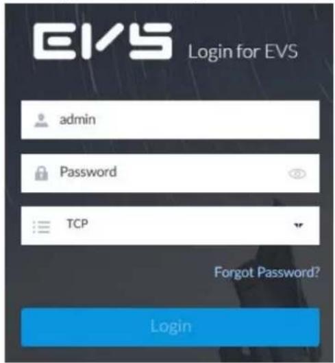
Step 2 Enter username and password.

- Click Login. For your device safety, change the admin password regularly and keep it well.
- In case you forgot password, click Forgot password to reset. See "6.8.3.2 Resetting Password" for detailed information.
Step 3 Select the login type among TCP, UDP and Multicast. Keep it TCP if you have no special requirement for TCP or UDP.
Step 4 Click Login.
System displays LIVE page.
3.4 Configuring Remote Device
Register remote device to the system. Here you can view the live video from the remote device, change remote device settings, and so on.
3.4.1 Initializing Remote Device
After you initialize the remote device, you can change remote device login password and IP address. Remote devices can be connected to the Device only after being initialized.
Step 1
Click

or click

on the configuration page, and then select DEVICE.
Figure 3-16 Device management
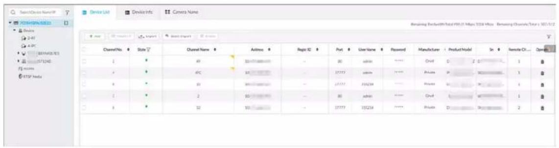
Step 2 On the Device List page, click Add.
Step 3 On the Smart Add page, click Smart Search.

To set search conditions, you can click .
Figure 3-17 Remote device
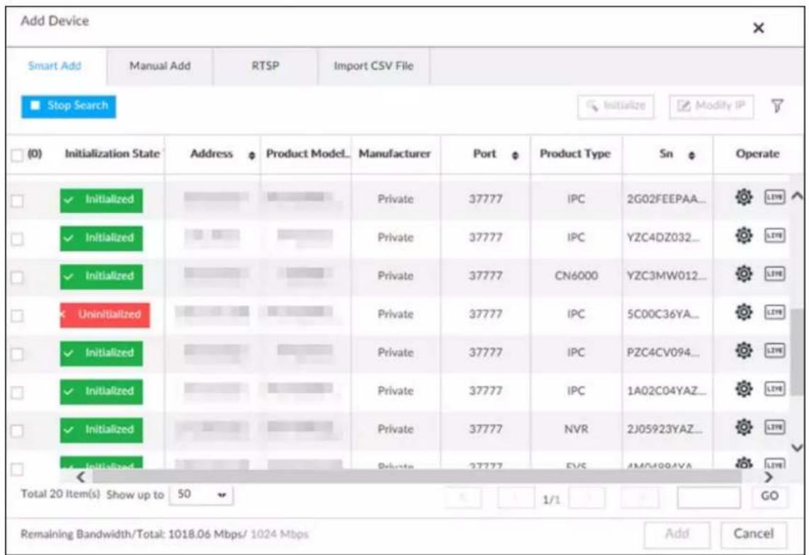
Step 4 Select the uninitialized remote device and then click Initialize.

Click Initialization status and then select Uninitialized, you can quickly filter the uninitialized remote device.
Figure 3-18 Initializing the Device
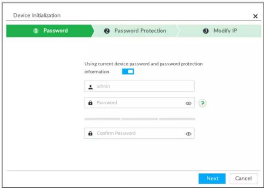
Step 5 Set remote device password and password protection.

Using current device password and password protection information is enabled by default. Keep it enabled so as to automatically use current device admin password and email information without manual configuration. Go to Step 6 if you keep it enabled.
1) To manually configure password, click to disable Using current device password and password protection information.
Figure 3-19 Password setting
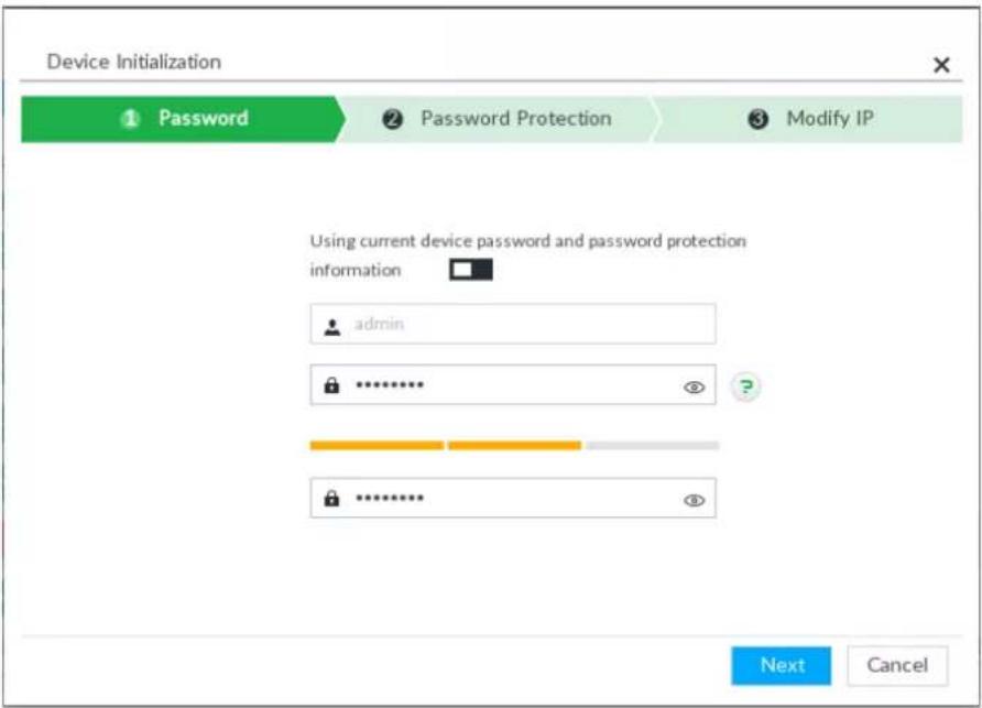
2) Set parameters.
Table 3-5 Description of password parameters
| Parameters Description | |
| Username | The default username is admin. |
| Password | In the New Password box, enter the new password and enter it again in the Confirm Password box.The password should consist of 8 to 32 non-blank characters and contain at least two types of characters among uppercase, lowercase, number, and special character (excluding '";: &). Enter a strong password according to the password strength indication. |
| ConfirmPassword | |
3) Click Next.
Figure 3-20 Password protection
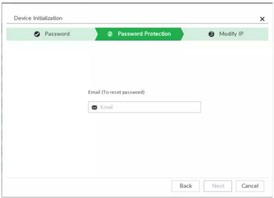
4) Set an email address.
Enter an email address. You can use the email address here to reset password in case you forgot password in the future.
Step 6 Click Next.
Figure 3-21 Modify IP
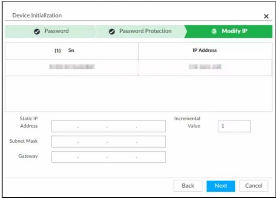
Step 7 Set camera IP address.
- When there is DHCP server in the network, select DHCP, and the remote device gets dynamic IP address automatically. It is unnecessary to enter IP address, subnet mask and gateway.
- Select Static, and then enter static IP address, subnet mask, default gateway and incremental value.

- After you enter incremental value, system can add the fourth address of the IP address one by one to automatically allocate the IP addresses.
- If you want to change several devices IP addresses at the same time, system allocates IP address of the same network segment.
- If there is IP conflict when changing static IP address, device pops up IP conflict dialogue box. If batch change IP address, device automatically skips the conflicted IP and begins the allocation according to the incremental value.
Step 8 Click Next.
Figure 3-22 Initialize
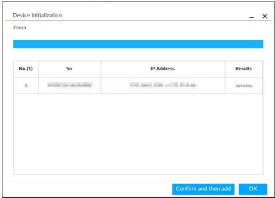
Step 9 Click Confirm and Add, or click OK.
- Click Confirm and Add: System completes initializing the remote device and then adds the remote device to the list. System goes back to Add device page.
- Click OK: System completes initializing remote device. System goes back to Add device page.
3.4.2 Adding Remote Device
Device supports smart add, manual add and template add.
Table 3-6 Add mode
| Add Mode Description | |
| Smart Add | Search for the remote devices on the same network and then filter to register. For details, see "3.4.2.1 Smart Add".It is useful if you do not know the exact IP address. |
| Manual Add | Enter the IP address, username and password of remote device. For details, see "3.4.2.2 Manual Add".For some remote devices, you can enter IP address, username, and password to register. |
| RTSP | Add remote devices through RTSP. For details, see "3.4.2.3 RTSP".To add stream media devices, you are recommended to choose RTSP. |
| Batch add (by CSV template) | Fill in information about remote device in the template, import the template to add the Device. For details, see "3.4.2.4 Batch Add".For batch adding, when IP address, username and other information of remote device is inconsistent, it is suggested to use this mode. |
3.4.2.1 Smart Add
Step 1 Click , and then select DEVICE.
Step 2 Click + or Add, and then select Smart Add.
Figure 3-23 Smart add
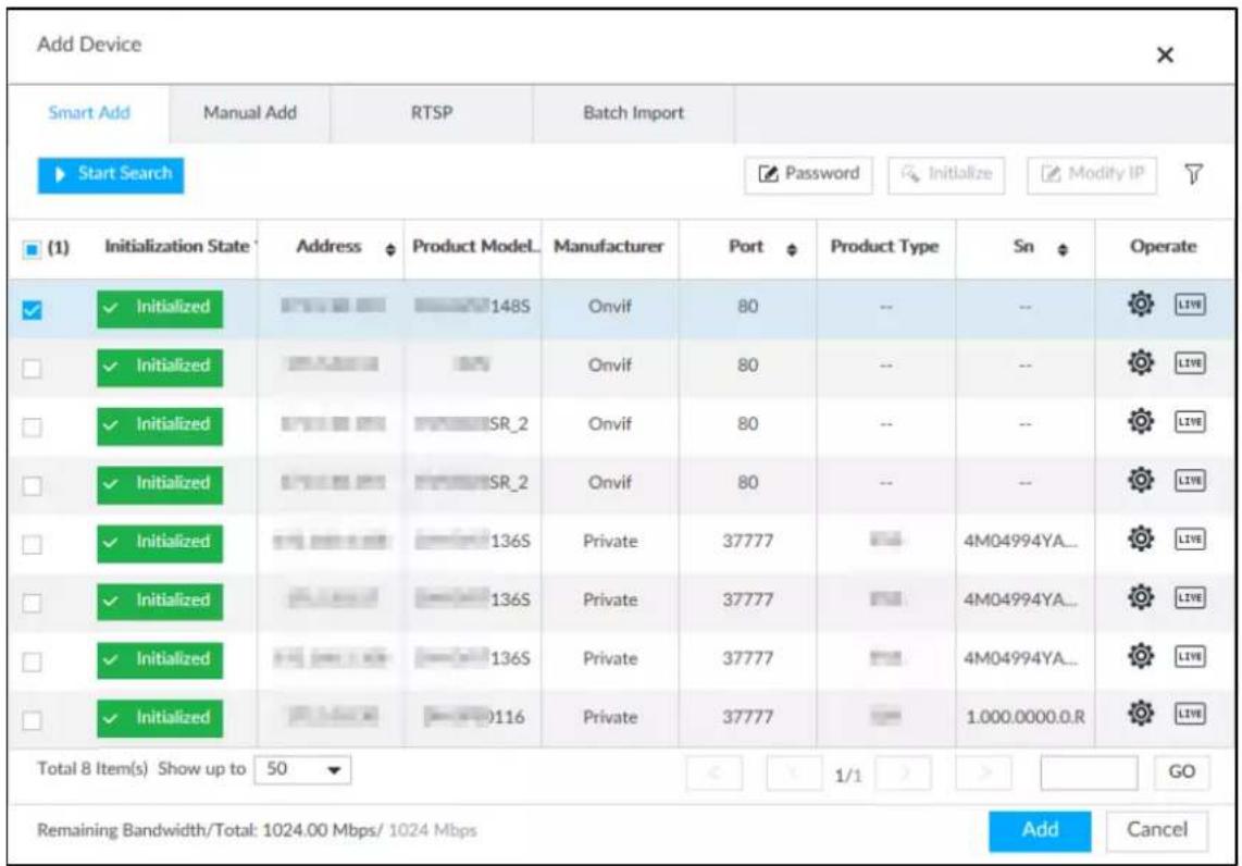
Step 3 Click Start Search.
©
To set search conditions, you can click .
Figure 3-24 Search results
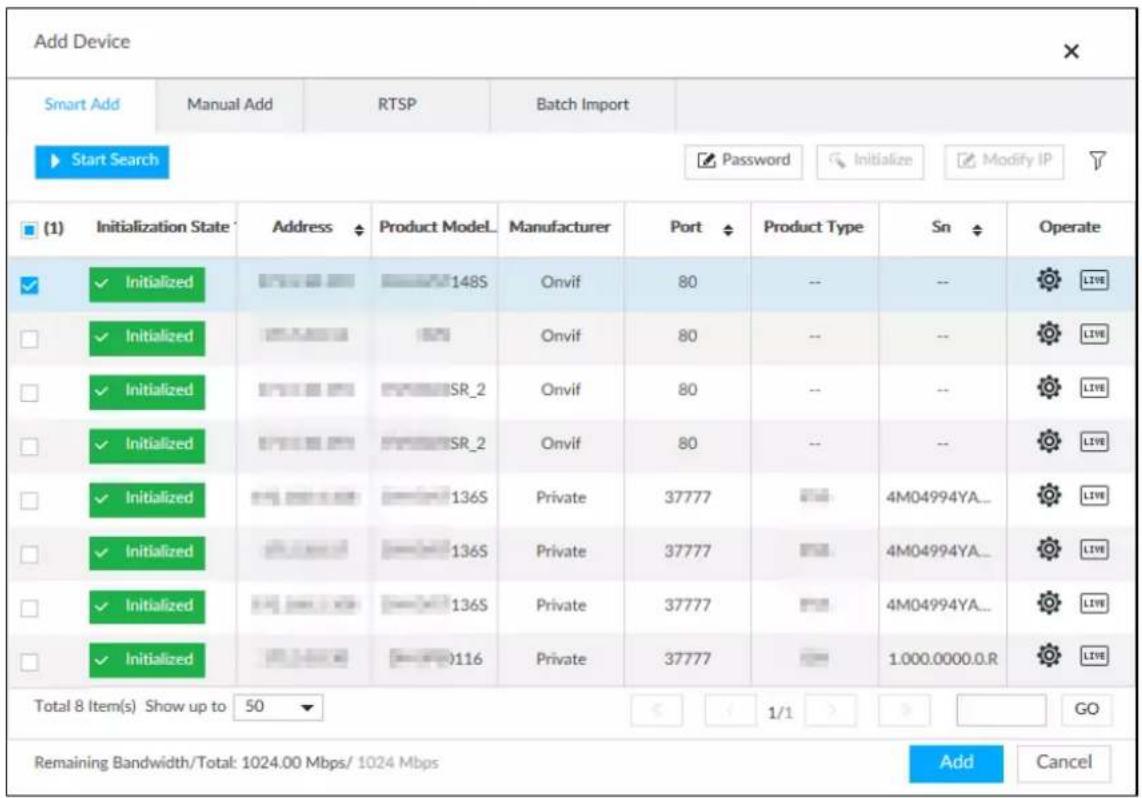
Table 3-7 Result description
| Parameters Description | |
| Start Search | Click Start Search to start searching remote device. Now it becomes Stop Search.Click Stop Search to stop searching remote device. |
| Password | Enter the username and password of the selected device for adding it. |
| Initialize | Select uninitialized remote device and then click Initialize to initialize remote device. See "3.4.1 Initializing Remote Device" for detailed information. |
| Modify IP | See "6.2.2.2 Changing IP Address" to change the registered device IP address. |
| Initialization State | Displays remote device initialization status.Click to filter initialized or uninitialized remote device. |
| Operation | Click LIVE to display real-time video from the remote device. See Figure 3-24.Click × or Close to close the real-time preview window.You can view the live video if admin password of the remote device is admin, or remote device admin password is the same as the system. |
| Bandwidth | Displays bandwidth remaining and the total bandwidth. |
Figure 3-25 Live view
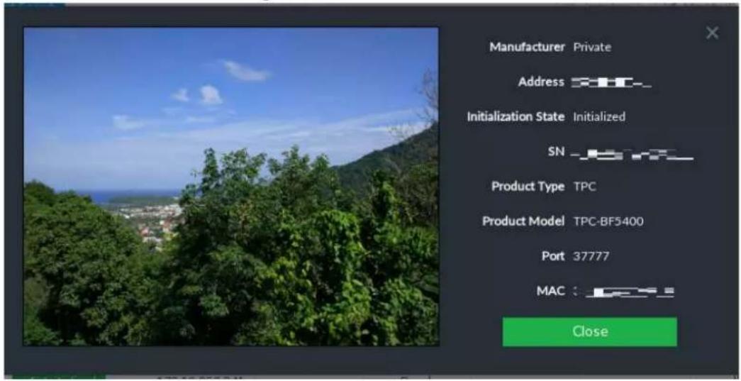
Step 4 Add a remote device.
Select a remote device, click Password, and then enter the username and password of the selected device. Click OK.

- If you do not enter device username and password, the system will try to add the Device by using the username and password of the current EVS.
- During the adding process, click Cancel, you can cancel adding process. Click Stop button of the corresponding remote device to cancel add.
Step 5 Click Add. The confirmation page is displayed.

- Double-click remote device IP address, username, password, manufacturer, port to change corresponding information.
- If system fails to add the remote device, see the reason on the Status column to change the remote device information and then click Retry to try to add again.
- If a remote device is exception due to network disconnection other reasons, it can also be added. It comes online after the exception is resolved.
Figure 3-26 Confirm
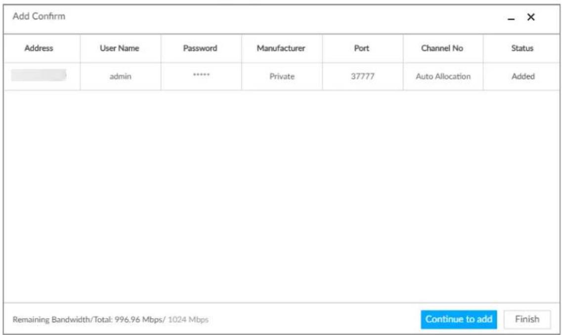
Step 6 Click Continue to add or Finish.
- Click Continue to add, device goes back to Smart add page to add more remote device.
- Click Finish to complete adding remote device process. Device displays Device page to view the newly added remote device information.
3.4.2.2 Manual Add
Step 1 Click , and then select DEVICE.
Step 2 Click + and then select Manual add.
Figure 3-27 Manual add
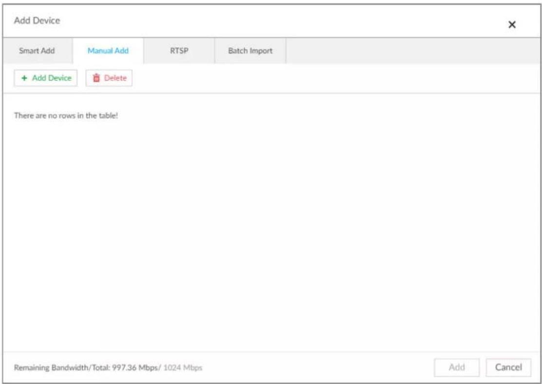
Step 3 Click Add Device.
Figure 3-28 Add device
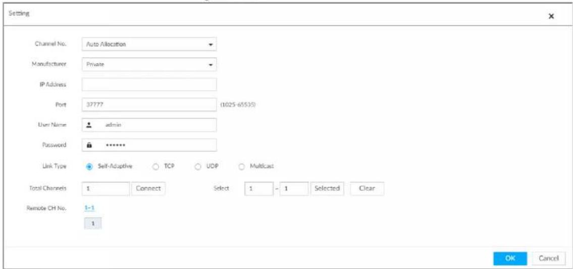
Step 4 Set parameters.
Table 3-8 Parameters of manual add
| Parameters Description | |
| Channel No. | Select a channel number for the remote device on IVSS.If you selectAuto Allocation, IVSS will provide a channel number automatically. |
| Manufacturer | Displays the connection protocol of the remote device. Default protocol of the system isPrivate. ClickPrivateto select other protocols. |
| IP Address | Enter the IP address of the remote device. |
| Device SN | Enter the unique SN allocated by the server for the remote device.When theManufacturerisRegister, you need to configure this parameter. |
| RTSP Mode | SelectSelf-adaptiveorCustomizeIf the mode isCustomize, enter the RTSP port number.When theManufacturerisOnviforOnvifs, the two parameters are available. |
| RTSP Port | |
| HTTP Port | Enter the HTTP port number. The default port number is 80. The value ranges from 1 through 65535. After changing the HTTP port number, you need to add the HTTP port number to the IP address in the address bar of the browser for login. |
| HTTPS Port | Enter the HTTP port number. The default port number is 80. The value ranges from 1 through 65535.When theManufacturerisOnvifs, you need to configure this parameter. |
| User Name | Enter the username and password of the remote device. |
| Password | |
| Port | Enter the port number of the remote device.When theManufacturerisPrivate, you need to configure this parameter. |
| Remote CH No. | Select the channel number for the remote device.1. Select a link type.2. To get the total number of channels, clickConnect.3. Enter the range of channels you need, and then clickSelected.4. ClickOK. |
Step 5 Select the remote device and then click Add. Device begins adding remote device and pops up the confirmation page.

- During the adding process, click Cancel, you can cancel adding process. Click Stop button of the corresponding remote device to cancel.
-
Double-click remote device IP address, username, password, manufacturer, port to change corresponding information.
-
If system fails to add the remote device, see the reason on the Status column to change the remote device information and then click Retry to try to add again. See Figure 3-29.
- If a remote device is exception due to network disconnection other reasons, it can also be added. It comes online after the exception is resolved.
Figure 3-29 Confirm
| Add Confirm | ||||||
| Address | User Name | Password | Manufacturer | Port | Channel No | Status |
| admin | ****** | Private | 37777 | Auto Allocation | Added | |
| Remaining Bandwidth/Total: 996.96 Mbps/ 1024 Mbps Continue to add Finish | ||||||
Step 6 Click Continue to add or Finish.
- Click Continue to add, device goes back to Smart add page to add more remote device.
- Click Finish to complete adding remote device process. Device displays Device page to view the newly added remote device information.
3.4.2.3 RTSP
Step 1 Click , and then select DEVICE.
Step 2 In the Device List page, click Add.
Step 3 Click RTSP.
Figure 3-30 RTSP
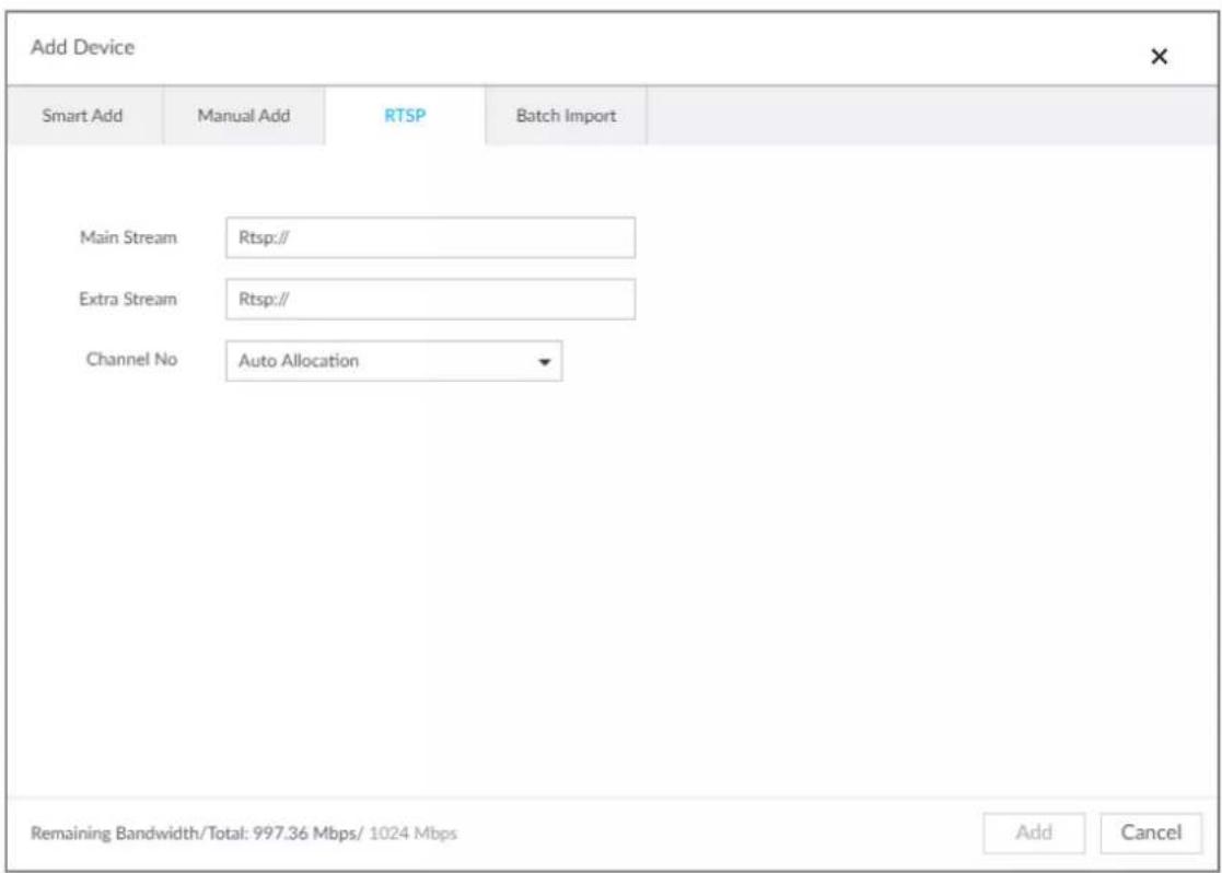
Step 4 Enter RTSP address as required.
RTSP address format is rtsp://
address>:
- Port: 554 by default.
- Channel: The channel number of the stream media device to be added.
- Subtype: Stream type. 0 for main stream, and 1 for sub stream.
Step 5 Select a channel No.
Step 6 Click Add.
3.4.2.4 Batch Add
Step 1 Click , and then select DEVICE.
Step 2 Click + , and then select Import CSV file tab.
Figure 3-31 Batch import
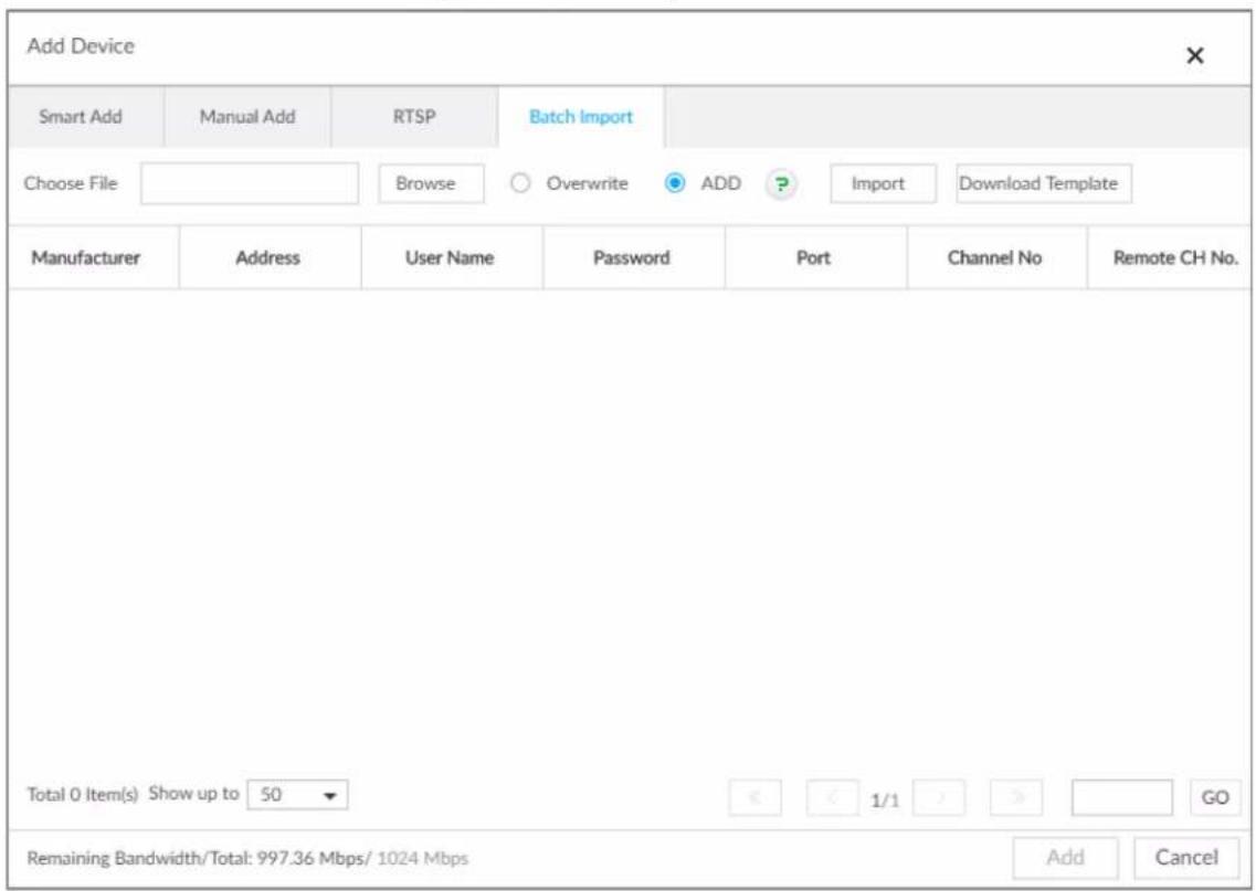
Step 3 Fill in template file.
1) Click Download Template to download template file.
File path might vary depending on page operations, and slight difference might be found on the actual page.
- At PCAPP, click ≡, and then select Download to view file saving path. For details, see "9.3 Viewing Downloads".
- Select file saving path during local operation.

- During web operations, files are saved under default downloading path of the browser.
2) Fill in template file and save according to your actual situation.
The following information of template file shall be filled in.

If information about remote device is not filled in completely, improve it after importing template.
Figure 3-32 Template
| Address | Regist ID | Port | Channel No. | Channel Name | Manufacturer | User Name | Password | Link Type | Remote CH No. | Product Model | SN |
Step 4 Import template file.
1) Click Browse to select the upgrade file.
2) Select an import mode and then click Import.
- Overwrite: The system removes the added remote devices before importing new devices.

If you select Overwrite, all the existing devices will be deleted.
- ADD: The system imports remote devices without deleting the existing ones.
Step 5 Select the remote device and then click Add.

- If information about remote device is not filled in completely, improve it after importing template.
- If the system fails to add the remote device, check the reason on the Status column, change the remote device information and then click Retry to try to add again.
Figure 3-33 Confirm
| Add Confirm | ||||||
| Address | User Name | Password | Manufacturer | Port | Channel No | Status |
| admin | ****** | Private | 37777 | Auto Allocation | Added | |
| Remaining Bandwidth/Total: 996.96 Mbps/ 1024 Mbps Continue to add Finish | ||||||
Step 6 Click Continue to add or Finish.
- Click Continue to add, device goes back to Smart add page to add more remote device.
- Click Finish to complete adding remote device process. Device displays Device manager page to view the newly added remote device information.
4 AI Operations
In addition to the basic video monitoring functions, the Device can also provide a number of AI functions including face recognition, people counting, video metadata, vehicle recognition, and IVS (behavior detections such as fence-crossing, intrusion, loitering, crowd gathering, parking and more.). This chapter introduces how to configure the AI functions respectively.
The AI detections are done by camera (AI by Camera). The intelligent analysis job is completed on the camera, and EVS just receives and processes the results.

● The AI functions might vary depending on the Device function capability.
- To use AI by Camera, complete AI detection configuration at remote device. See remote device user's manual.
- The AI by Camera tab does not appear if the current camera does not support this function.
- Some AI features are conflicting. Do not enable conflicting AI features at the same time.
4.1 Face Detection
System triggers alarms when human faces are detected within the detection zone.
4.1.1 Enabling AI Plan
You need to enable AI plan first.

• AI plan is available on select models.
- You need first enable the corresponding AI plan; otherwise the AI function does not work.
- The Device automatically shows the AI functions available on the connected cameras.
Step 1 Click 🎨, or click + on the configuration page, and then select EVENT.
Step 2 Select a camera in the device tree on the left.
Step 3 Select AI Plan > AI Plan > AI Plan.

- The page might vary depending on the function capabilities of cameras.
- If the camera is a PTZ camera, configure presets on the camera system first, and then you can set AI features for each preset of the PTZ camera.
Figure 4-1 Al plan (1)
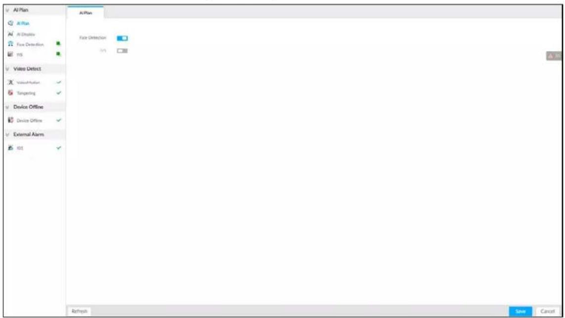
Figure 4-2 AI plan (2)
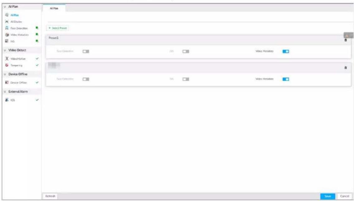
Step 4
Click

to enable AI detection plan. The icon becomes

When there is a conflict between the to-be-enabled AI plan and an enabled plan, disable the enabled plan first.
Step 5
Click Save.
4.1.2 Configuring Face Detection
Configure alarm rule of face detection.
Step 1
Click

or click

on the configuration page, and then select EVENT.
Step 2 Select a remote device in the device tree on the left.
Step 3 Select AI Plan > Face Detection.
Figure 4-3 Face detection
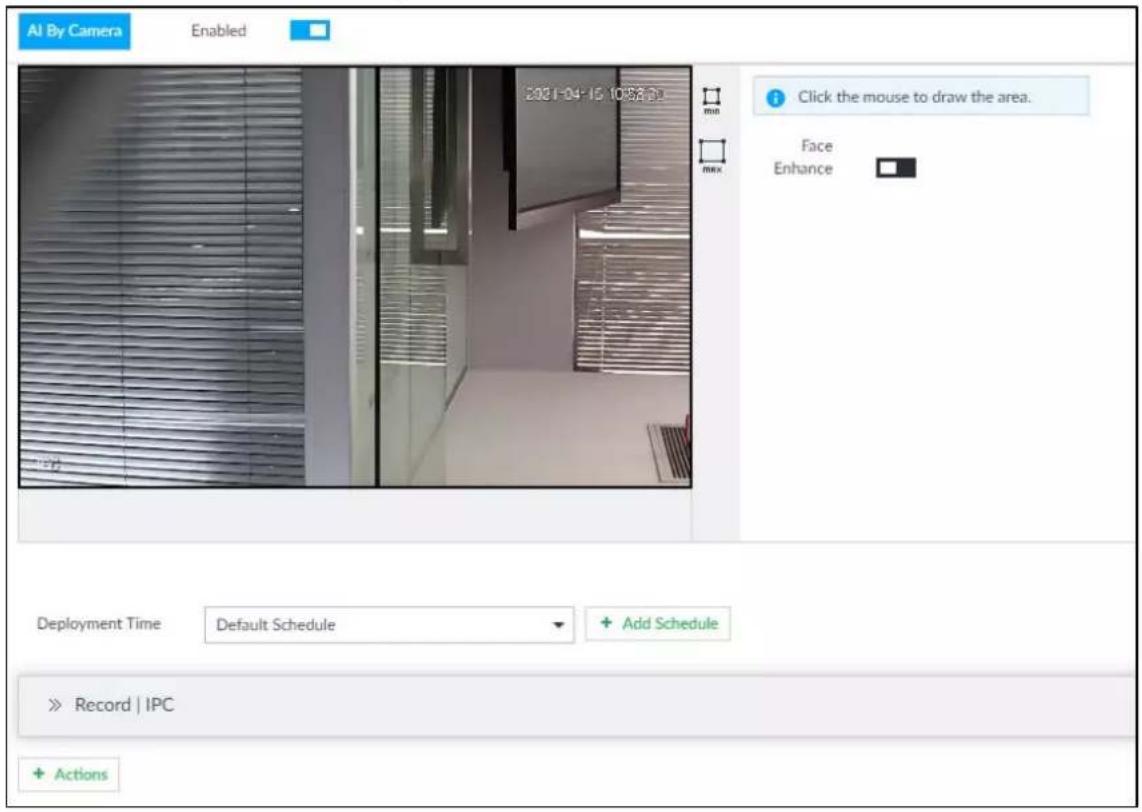
Step 4 Click to enable face detection.

Support the Face Enhance function. After enabling Face Enhance function, system displays enhanced human face zone on the surveillance window.
Step 5 Set detection region on the video (yellow area).
Figure 4-4 Area
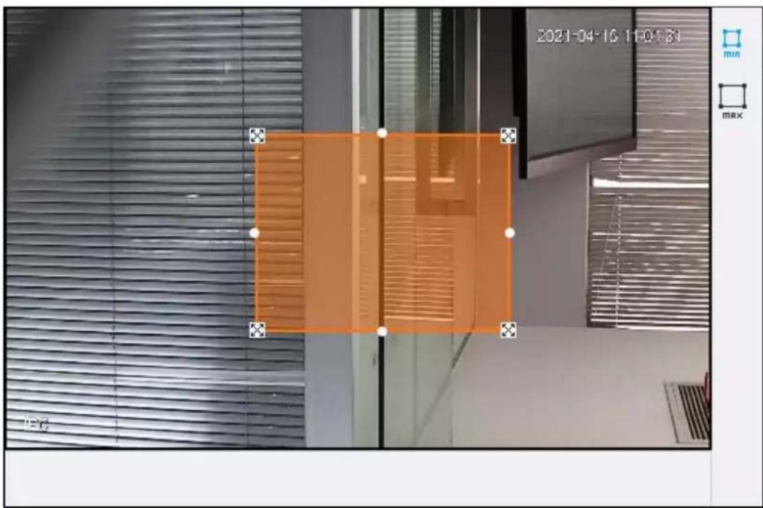
- Click ✗ or white dot on detect region frame, and drag to adjust its size.
- Click min or max to set the minimum size or maximum size of the face detection area. System triggers an alarm once the size of detected target is between the maximum size and the minimum size.
Step 6 Click Deployment Time to select schedule from the drop-down list.
After setting arm period, system triggers corresponding operations when there is a motion detection alarm in the specified period.

You can select an existing schedule from the Deployment Time drop-down list. You can also add a new schedule. For details, see "6.9.3 Schedule".
Step 7 Click Action to set alarm action. See "6.4.1 Alarm Actions" for detailed information.
Step 8 Click Save.
4.1.3 Live View of Face Detection
You can view real-time face detection images and video.
4.1.3.1 Setting AI Display
You can configure display rule of face detection results.

Before using this function, ensure that view has been created. See "5.1.1 View Management" for detailed information.
Step 1
On the LIVE page, click

and select the Face tab.

- Click Sync from AI-Dis., obtain global smart detection display rule of EVS. See "6.4.2.4.2 Setting AI Display" for detailed information.
- Click Apply to all windows to copy current configuration to other window(s).
Figure 4-5 Face
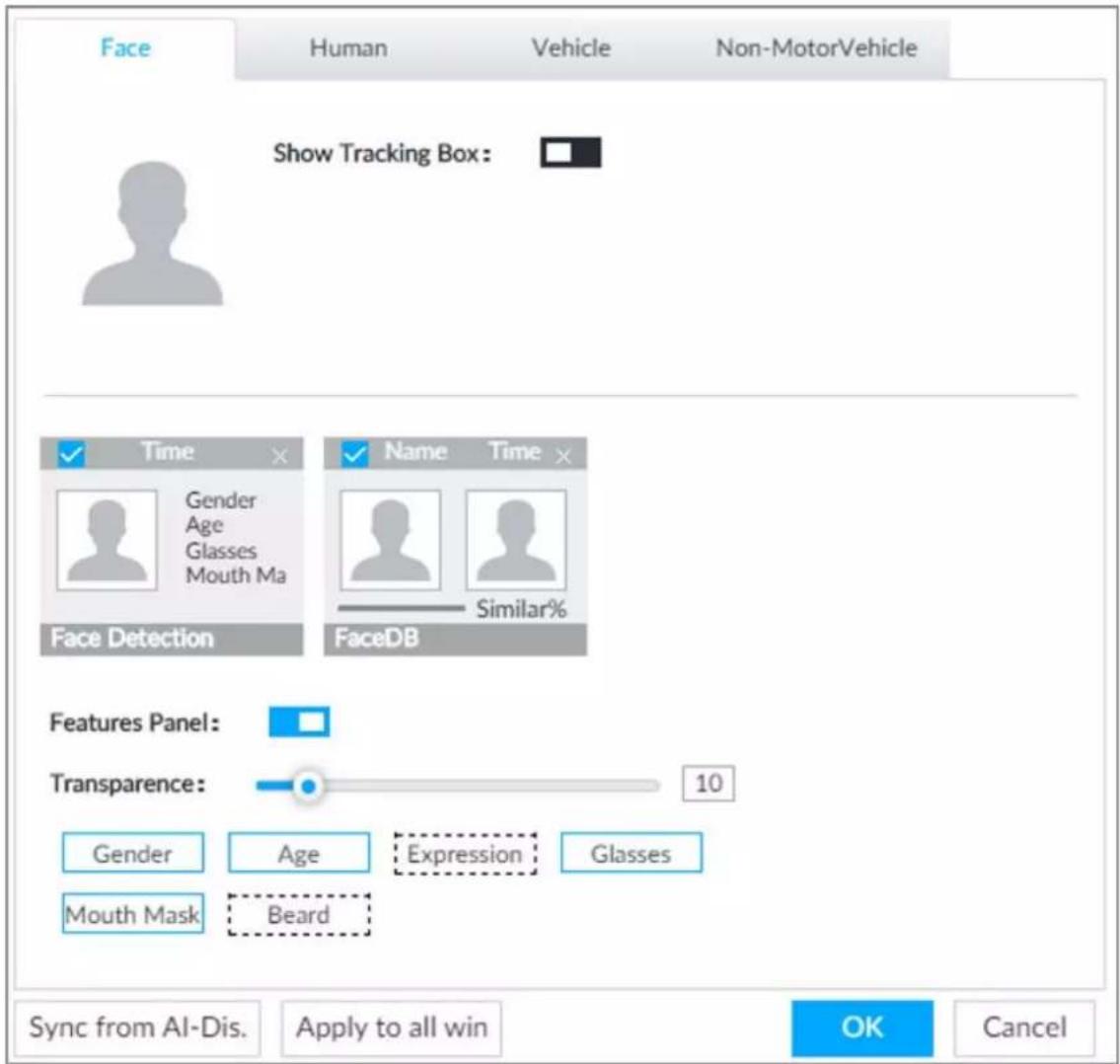
Step 2 Enable Show Tracking Box by clicking

After it is enabled, when the system detects face or human, the window will display corresponding rule box.
Step 3 Enable Features Panel, and select feature(s) you want to display.
1) Click □ next to Features Panel, to enable the function. When the panel is enabled, the snapshots of detected faces are displayed on the live view.
2) Click □ to select Face Detection tab. √ indicates that the panel is selected.
3) (Optional) Drag 🔒 to adjust features panel transparency. The higher the value, the more transparent the features panel.
4) (Optional) Select the features you need to display.
• System supports displaying 4 feature types.
- System has checked four features by default. To select other features, cancel the selected features, and then select the ones you need.
Step 4 Click OK to save the configuration.
4.1.3.2 Live View
Go to the LIVE page, enable view, and then view videos are displayed. See Figure 4-6.
● The view window displays currently detected face rule boxes.
● Features panels are displayed on the right side in real time.
The features panel displays detection time, face snapshot and face features details.
Figure 4-6 Live
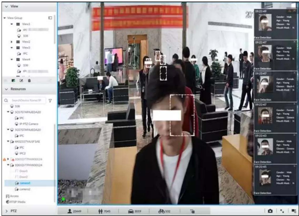
Point to a features panel, and click 📄 or double-click the detected image, so the system starts to play back the recorded videos (about 10 s) at the time of snapshot.
4.1.3.3 Face Records
On the LIVE page, click 🔥. The FACE TOTAL page is displayed. Click 🔥. And then select Face Detection. The latest face detection records are displayed.
Figure 4-7 Detection image
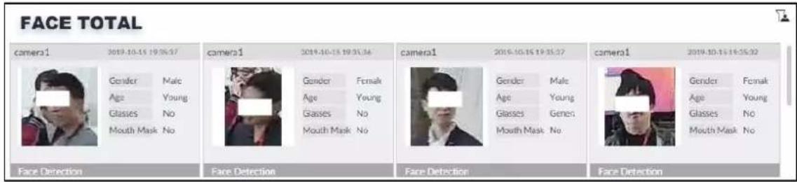
On the FACE TOTAL page, the following operations are available.
- Point to a piece of face record, click 📋 or double-click the detected image, and then the system starts to play back the recorded videos (about 10 s) at the time of snapshot.
- Point to a piece of face record, click 📋, and then you can save that record locally including the video and pictures.
4.1.4 Face Search
Search for face detection information, including face detection image, record and features.
4.1.4.1 Searching by Property
Step 1 Click + , select AI SEARCH > Search by Face.
Figure 4-8 Search by face
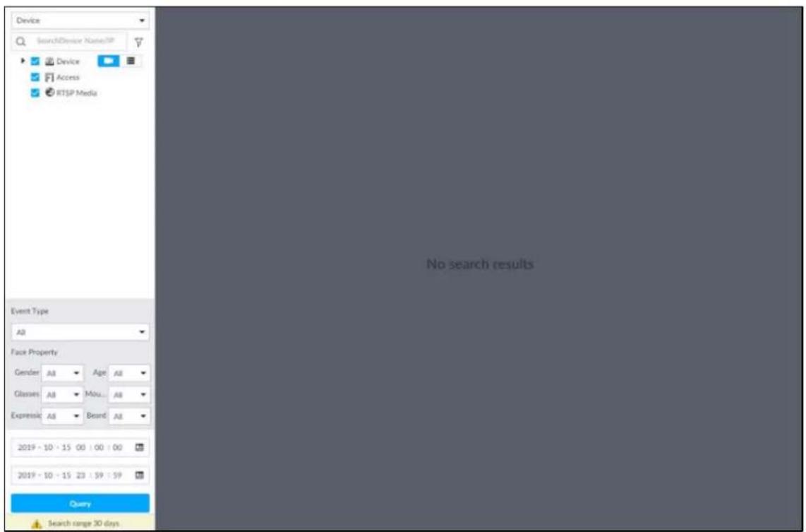
Step 2 Select a remote device, and then set Event Type to be Face Detection.

In the Event Type drop-down list, if you select All, the search results will include both face detection records and face recognition records.
Step 3 Set face property and time.
Step 4 Click Query.
Figure 4-9 Search results
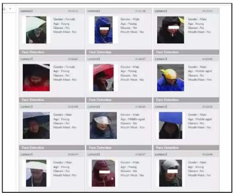
Point to a piece of record, and then the following icons are displayed.
Table 4-1 Description
| Icon Operation | |
| Select one by one: Click the panel or move the mouse pointer onto the panel, and then click to select the panel.means it is selected.Batch select: Check All to select all panels on the page. | |
| Click or double-click the panel, the system starts to play back the recorded videos (about 10 s). | |
| Click or select the panel and click to export images, videos and Excel to designated storage path.After setting alarm linkage snapshot, during exporting images, the system exports detected images and panoramic images at the time of snapshot. | |
4.1.4.2 Exporting Face Records
The search results of face records can be exported. You can select to export video, picture and excel.

- The exported alarm-linked snapshot contains the face snapshot and the background picture.
- To save the background picture, make sure that you have configured alarm-linked snapshot storage.
Figure 4-10 Search results of face records
| All | All(1) Export | Total 40328 Records | ||
| 2019-10-16 | camera1 | 00:00:00 | camera1 00:00:00 | camera1 00:00:00 |
| Gender : Male Age : Young Glasses : Black-fra... Mouth Mask : No | Gender : Male Age : Young Glasses : General Mouth Mask : No | Gender : Female Age : Young Glasses : No Mouth Mask : No | ||
| Face Detection | Face Detection | |||
| camera1 | 00:00:02 | camera1 00:00:03 | camera1 00:00:04 | |
| Gender : Female Age : Child Glasses : No Mouth Mask : No | Gender : Male Age : Young Glasses : No Mouth Mask : No | Gender : Female Age : Young Glasses : General Mouth Mask : No | ||
| Face Detection | Face Detection | |||
| camera1 | 00:00:06 | camera1 00:00:07 | camera1 00:00:08 | |
| Gender : Male Age : Middle-agent Glasses : No Mouth Mask : No | Gender : Male Age : Young Glasses : Black-fra... Mouth Mask : No | Gender : Male Age : Young Glasses : General Mouth Mask : No | ||
| Face Detection | Face Detection | |||
| camera1 | 00:00:09 | camera1 00:00:09 | camera1 00:00:09 | |
| Gender : Male Age : Young Glasses : No Mouth Mask : No | Gender : Male Age : Young Glasses : General Mouth Mask : No | Gender : Male Age : Young Glasses : General Mouth Mask : No | ||
| Face Detection | Face Detection | |||
| camera1 | 00:00:10 | camera1 00:00:10 | camera1 00:00:11 | |
| Gender : Male Age : Young Glasses : Black-fra... Mouth Mask : No | Gender : Female Age : Young Glasses : Black-fra... Mouth Mask : No | Gender : Male Age : Young Glasses : No Mouth Mask : No | ||
- Export in batches
Export more than one record. Support specifying file formats.
Step 1 Select more than one record.

To export all records, select the checkbox of All.
Step 2 Click ↗, and then select file formats.
Figure 4-11 File format
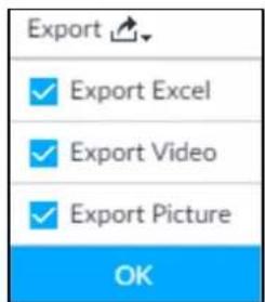
Step 3 Click OK, and then follow the onscreen instructions to finish exporting.
- Export one by one
Export one piece of record. The exported file contains excel, snapshot and video by default.
Step 1 Point to a piece of record, and then click.

Step 2 Select a file type between DAV and MP4, set the saving path, and then click OK.
4.2 Face Recognition
The system compares captured face with the face database. When the similarity reaches the threshold as you have defined, an alarm will be triggered.

Make sure that the face database has been configured on the camera. For details, see user's manual of camera.
4.2.1 Enabling AI Plan
To use AI by Camera, you need to enable the corresponding AI plan first. For details, see "4.1.1 Enabling AI Plan".
4.2.2 Configuring Face Recognition
Configure face recognition rules.
Step 1 Click 🎨, or click + on the configuration page, and then select EVENT.
Step 2 Select remote device in the device tree on the left.
Step 3 Select AI Plan > Face Recognition.
Figure 4-12 Face recognition
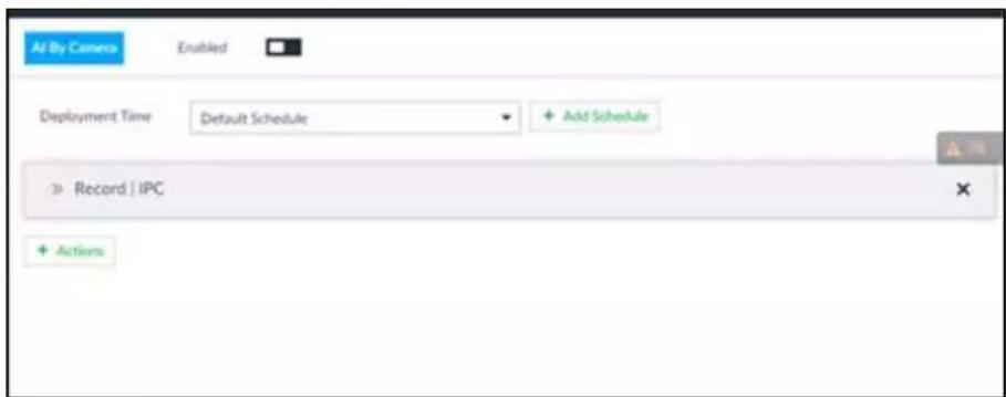
Step 4 Click □ to enable face recognition.
Step 5 Click Deployment Time to select schedule from the drop-down list.
After setting arm period, system triggers actions when there is a motion detection alarm in the specified period.
- Click View Schedule to view detailed schedule settings.
- If the schedule is not added or the added schedule does not meet actual needs, click Add Schedule. See "6.9.3 Schedule" for detailed information.
Step 6 Click Actions to set alarm actions. For details, see "6.4.1 Alarm Actions".
Step 7 Click Save.
4.2.3 Live View of Face Recognition
Smart panel display. You can view real-time face detection and human face recognition images.
4.2.3.1 Setting AI Display
You can configure display rule of AI detection results.

Before using this function, ensure that view has been created. See "5.1.1 View Management" for detailed information.
Step 1 On the LIVE page, open a view window.
- Click Sync from AI-Dis., obtain global smart detection display rule of EVS. See "6.4.2.4.2 Setting AI Display" for detailed information.
- Click Apply to all windows to copy current configuration to other window(s).
Figure 4-13 Face
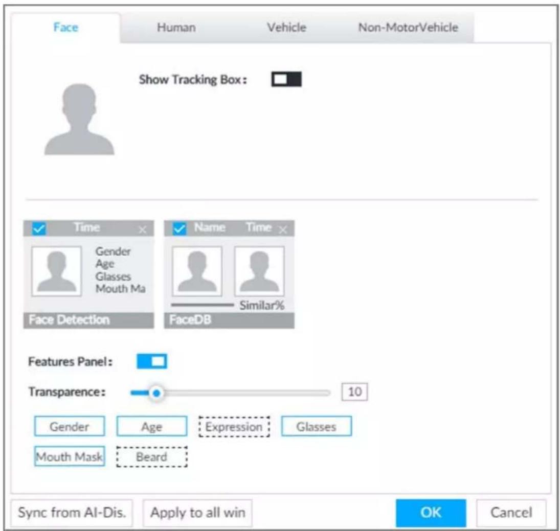
Step 3 Click □ next to Show Tracking Box, to enable the function.
After it is enabled, when the system detects face or human, the window will display corresponding rule box.
Step 4 Enable features panel.
1) Click □ next to Features Panel, to enable the function. When the panel is enabled, the snapshots of detected faces are displayed on the live view.
2) Click □ to select Face DB tab and Face Recognition tab. √ indicates that the panel is selected.
- If the Face DB panel is selected, it is displayed on the live video when the similarity between a detected face and one in the face database reaches the threshold.
- If the Face Recognition panel is selected, it is displayed on the live video when the similarity between a detected face and one in the face database does not reach the threshold.
3) (Optional) Drag 📷 to adjust features panel transparency. The higher the value, the more transparent the features panel.
4) (Optional) Select the features you need to display.
● System supports displaying 4 feature types.
- System has checked four features by default. To select other features, cancel the selected features, and then select the ones you need.
Step 5 Click OK to save the configuration.
4.2.3.2 Live View
Go to the LIVE page, enable view, and then device displays view video.
- The view window displays currently detected face rule box.
- The right side displays features panel.
The features panel displays detection time, face snapshot and face features.
Point to a features panel, and then click 📄 or double-click the detected image, so the system starts to play back the recorded videos (about 10 s) at the time of snapshot.
4.2.3.3 Face Total
On the LIVE page, click 📁. Face detection panel is displayed. Point to a panel, and the operation icons are displayed.
Figure 4-14 Detection image
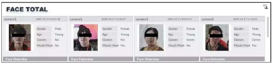
- Point to a panel, and click 📋 or double-click the detected image, so the system starts to play back the recorded videos (about 10 s) at the time of snapshot.
- Point to a panel, click 📄, and then you can save that record locally.
4.2.4 Face Search
Search for face detection information, including face detection image, record and features. Search according to record and image.
Procedure
Step 1
Click

select AI SEARCH > Search by Face.
Figure 4-15 Search by face
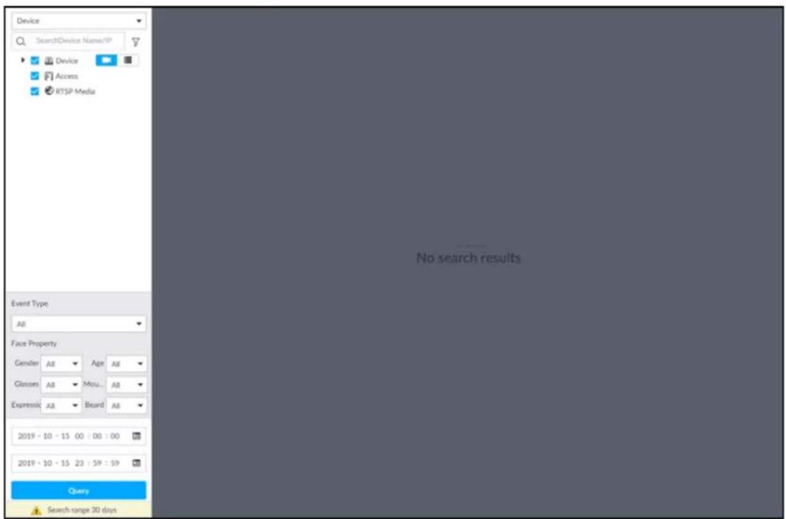
Step 2 Select a remote device, and then set Event Type to be Face Detection.

In the Event Type drop-down list, if you select All, the search results will include both face detection records and face recognition records.
Step 3 Set face property and time.
Step 4 Click Query.
Figure 4-16 Search results
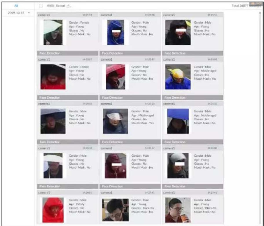
Related Operations
Point to a piece of record, the following icons are displayed.
Table 4-2 Description
| Icon Operation | |
| [2CKX] | Select one by one: Click the panel or move the mouse pointer onto the panel, and then click  to select the panel. [2800] means it is selected.Batch select: Check All to select all panels on the page. to select the panel. [2800] means it is selected.Batch select: Check All to select all panels on the page. |
| [16WG] | Click [4KWDS] or double-click the panel, the system starts to play back the recorded videos (about 10 s). |
 | Click [H43X] or select the panel and click ↗ to export images, videos and Excel to designated storage path.After setting alarm linkage snapshot, during exporting images, the system exports detected images and panoramic images at the time of snapshot. |
4.3 People Counting
Statistics of in-area people number, and queuing number.

- The people counting function is only available with AI by Camera. Make sure that the camera has been configured with people counting rules.
- The old people counting data will be overwritten when the storage space is runs out. You are recommended to back up the data in time.
4.3.1 Enabling AI Plan
To use AI by Camera, you need first enable the corresponding AI plan; otherwise the AI function does not work. For details, see "4.1.1 Enabling AI Plan".
4.3.2 People Counting
Configure this function to count the number of people in and out of the detection area. When the statistical number is larger or smaller than the threshold, an alarm is triggered.
Step 1 Click ⚙️, click +, and then select EVENT.
Step 2 Select a camera in the device tree, and then select AI Plan > People Counting > In Area No. Figure 4-17 In Area No.
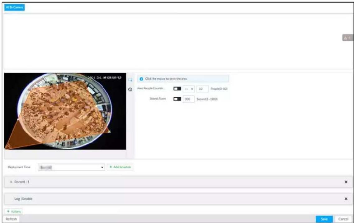
Step 3 Click to set a people counting area. Click and drag ✗ to adjust the position and length.
- Click the white dot on the frame of the area to add turning corners.
- Click to restore to the default area.
Step 4 Set parameters.
Table 4-3 Parameters description of people counting
| Parameters Description | |
| Enable | Click to enable the selected area. |
| Name Enter area name | |
| Area People Counting Alarm | 1. Click to enable the alarm.2. Set people number threshold.Select >=▼, and enter a threshold value. When the people number in the area is greater than the threshold, an alarm will be triggered.Select <=▼, and enter a threshold value. When the people number in the area is smaller than the threshold, an alarm will be triggered. |
| Strand Alarm | 1. Click to enable the alarm.2. Set time threshold for the alarm. When the dwell time of any person in the area is greater than the threshold, an alarm will be triggered. |
Step 5 Select a schedule in the Deployment Time drop-down list.
Alarms are triggered only within the scheduled time.
Step 6 Click Actions to set alarm linkage actions. For details, see "6.4.1 Alarm Actions".
Step 7 Click Save.
4.3.3 Queuing Detection
The system counts the number of people queuing in the detection area. When the number of people exceeds the threshold or the queue time is longer than the pre-defined time, an alarm is triggered.
Step 1 Click , click + , and then select EVENT.
Step 2 Select a camera in the device tree, and then select AI Plan > People Counting > Queuing.
Figure 4-18 Queuing
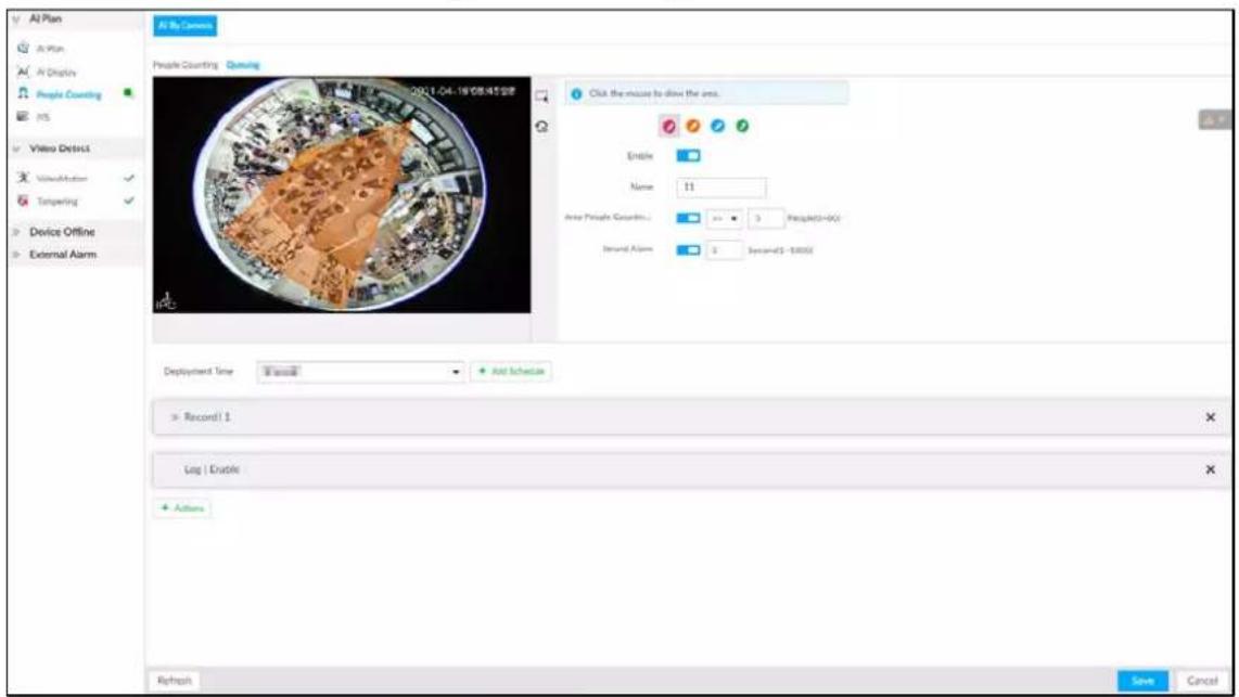
Step 3 Draw a queuing detection area.
1) Click to draw the first detection area.
Click to draw more areas. You can draw 4 areas at most.
2) Click to edit the area.
◇ Click and drag ✗ to adjust the position and length.
◇ Click the white dot on the frame of the area to add turning corners.
◇ Click to restore to the default area.
Step 4 Set parameters.
Table 4-4 Parameters description of queuing detection
| Parameters Description | |
| Enable | Click to enable the selected area. |
| Name | Enter the area name |
| Area People Counting Alarm | 1. Click to enable the alarm.2. Set people number threshold.Select >=▼, and enter a threshold value. When the people number in the area is greater than the threshold, an alarm will be triggered.Select <=▼, and enter a threshold value. When the people number in the area is smaller than the threshold, an alarm will be triggered. |
| Queuing Time Alarm | 1. Click □ to enable the alarm.2. Set time threshold for the alarm. When the queuing time of any person in the area is longer than the threshold, an alarm will be triggered. |
Step 5 Select a schedule in the Deployment Time drop-down list.
Alarms are triggered only within the scheduled time.
Step 6 Click Actions to set alarm linkage actions. For details, see "6.4.1 Alarm Actions".
Step 7 Click Save.
4.3.4 Live View
On the LIVE page, enable a view window that contains people counting video.
The live video which shows real-time people number and queuing time is displayed.
Figure 4-19 Live view
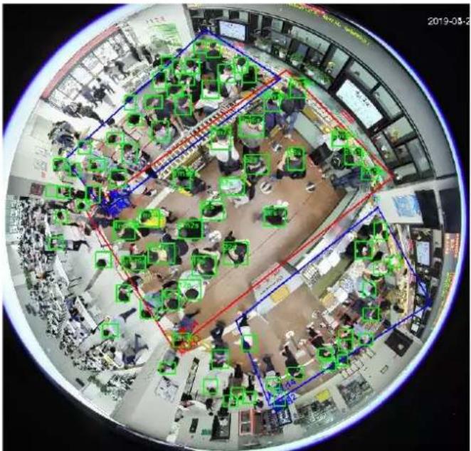
The live video displays real-time people number in the region, and the region frame flashes red once there is an alarm. The queue-detection live view also shows head frames and the dwell time of each person.
4.4 Video Metadata
The system analyzes real-time video stream to detect the existence of 4 target types: human, human face, motor vehicle, non-motor vehicle. Once a target is detected, the system can record video, take snapshots and trigger alarms.
This section introduces how to configure the video metadata feature from enabling it and selecting target types to setting the live view of video metadata.
4.4.1 Enabling AI Plan
Enable AI plan when AI by Camera is used. See "4.1.1 Enabling AI Plan" to enable AI detect function.
4.4.2 Configuring Video Metadata
After enabling video metadata, EVS links the current remote device for taking snapshots when alarm is triggered.

Video metadata cannot be enabled at the same time with face detection and IVS, because it conflicts with the two functions.
Step 1 Click 🎨 or + , and then select EVENT.
Step 2 Select a device from the device tree at the left side.
Step 3 Select AI Plan > Video Metadata.
Figure 4-20 Video metadata
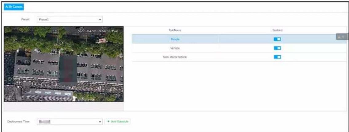
Step 4 Select the detection target.
- People: Click the corresponding □ to enable people detection. Face detection can also be enabled at the same time.
- Vehicle: Click the corresponding □ to enable vehicle detection.
- Non-Motor Vehicle: Click the corresponding ☐ to enable non-motor vehicle detection.
Step 5 Click Deployment Time drop-down list to select schedule.
EVS links alarm event when an alarm is triggered within the schedule configured.
- Click Add Schedule to add new schedule if no schedule is added or the existing schedule does not meet requirements. For details, see "6.9.3 Schedule".
- Click View Schedule to view details of schedule.
Step 6 Click Save.
4.4.3 Live View of Video Metadata
View the detection results of face, people, motor vehicle and non-motor vehicle on the LIVE page.
4.4.3.1 Setting AI Display
Set the filtering conditions to display AI detection results.

Create view(s) before setting filtering conditions. To create a view, see "5.1.1 View Management".
Step 1 Select a view from LIVE > View > View Group.
Step 2 Click ☐ at the lower side of the LIVE page, and then select Face, Human, Vehicle or Non-Motor Vehicle.

The figure uses Human for example. The page is for reference only.
Figure 4-21 Human
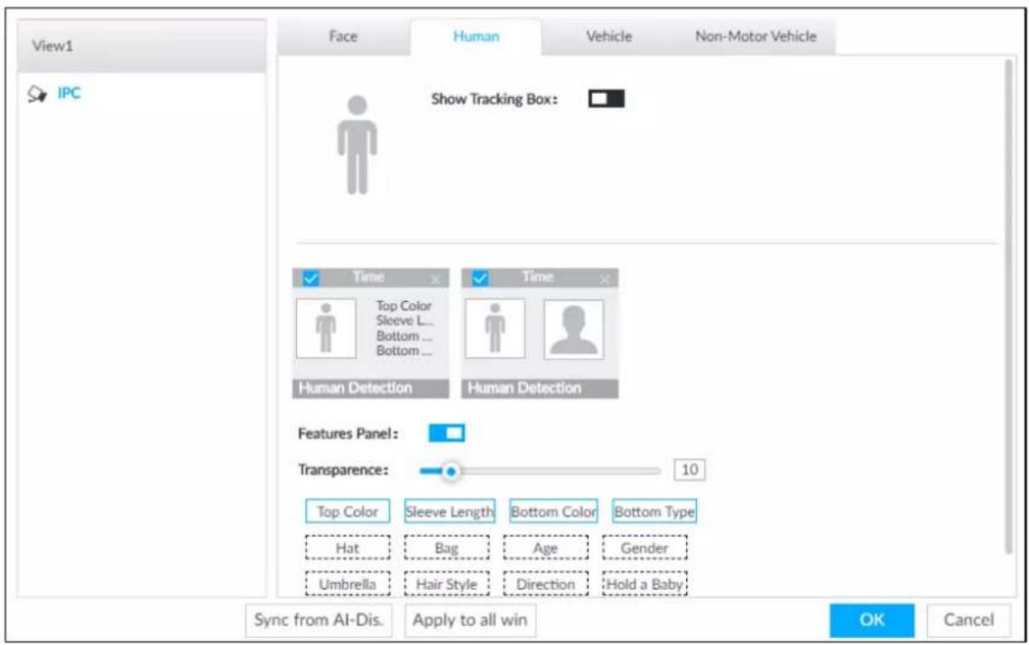
Step 3 Click □ next to Show Tracking Box, and then a tracking box is displayed in the video when target that meets the filtering conditions is detected.
Step 4 Configure feature panel.
1) Click next to Features Panel to enable feature panel.
A features panel is displayed on the right side of the video when target that meets the conditions is detected.
2) Click □ to select the panel type, for example, the Human Detection tab.
3) (Optional) Drag to adjust the transparency of panel. The higher the value, the more transparent the panel.
4) (Optional) Select the features to be displayed in the panel.
• Up to 4 features can be displayed.
- 4 features are selected by default. To select another feature, click the selected feature to cancel it, and then click the feature to be displayed.
Step 5 Click OK.
4.4.3.2 Live View
On the LIVE page, select a view from View Group, and the video image of the view will be displayed. See Figure 4-23.
- Rule box is displayed in real-time in the video image. Different detection targets correspond to different colors of rule box.
● Features panels are displayed on the right side of the video image.
Figure 4-22 Live
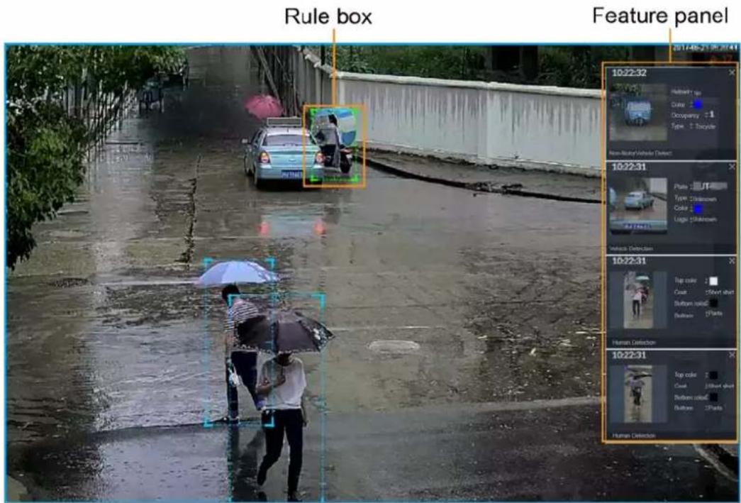
Point to the features panel, and then click ☐, or double-click the detected image to play back the video record (10 s before and after the snapshot).
4.4.3.3 Detection Statistics
View the detection statistics of human, motor vehicle and non-motor vehicle.
4.4.3.3.1 Human
On the LIVE page, click 📁, the PEOPLE TOTAL page is displayed.
Click 📋, and then select Snap With Face and Snap Without Face. The information of detected human and face is displayed.
- Point to the snapshot, and then click 📋 or double-click a pted picture to play back the video record (10 s before and after the snapshot).
- Point to the snapshot, and then click → to export the video record to specified saving path.
4.4.3.3.2 Motor Vehicle
On the LIVE page, click 🙏, the VEHICLE TOTAL page is displayed.
Click 📋, and then select Vehicle Recognition, the information of detected vehicles is displayed. See Figure 4-24.
Figure 4-23 Motor vehicle detection
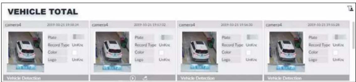
- Move the mouse pointer to the panel, and then click 📋, or double-click detected picture to play back the video record (10 s before and after the snapshot).
- Move the mouse pointer to the panel, and then click 📋 to export the video record to specified saving path.
4.4.3.3.3 Non-motor Vehicle
On the LIVE page, click 📖, the NONMOTOR TOTAL page is displayed.
Click 📁, and then select Snap With Face and Snap Without Face. The information of detected non-motor vehicles is displayed.
Figure 4-24 Non-motor vehicle detection
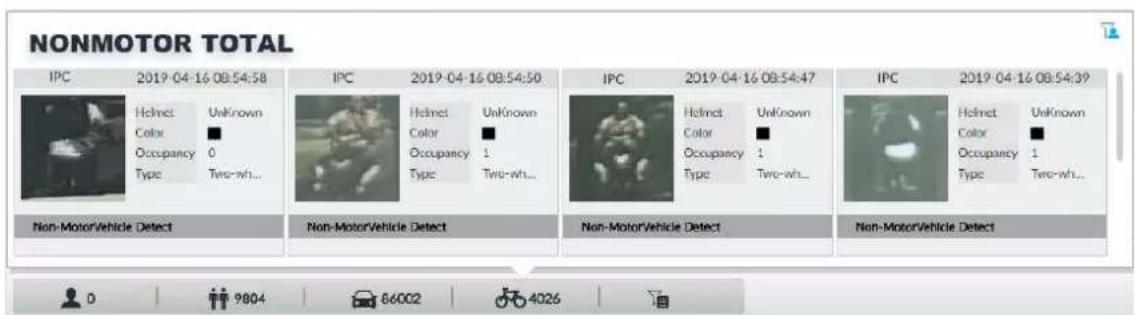
- Move the mouse pointer to the detected information, and then click 🔒, or double-click detected picture to play back the video record (10 s before and after the snapshot).
- Move the mouse pointer to the detected information, and then click 📋 to export the video record to specified saving path.
4.4.4 AI Search
Select device and set properties to search for detection results.
4.4.4.1 Human Search
Select device and set human properties to search human detection results.
Step 1 Click + , and then select AI SEARCH > Search by Human.
Figure 4-25 Search by human
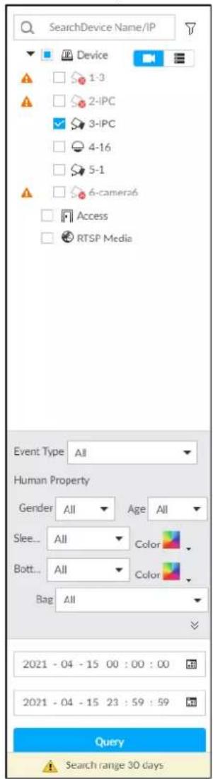
Step 2 Select a device, and then set human properties and time period.
Click or to set the color. means more than one color.
Step 3 Click Query.
- If face is captured, the human and face snapshots are displayed.
- If no face is captured, the human snapshot and human properties are displayed.
Figure 4-26 Search result
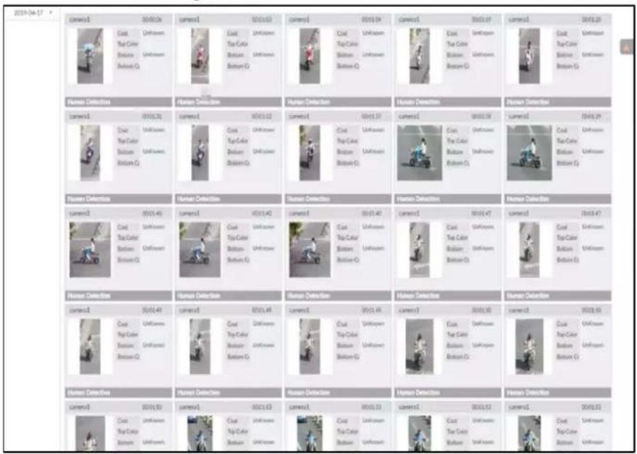
Related Operations
Point to one displayed panel, and the icons are displayed.
Table 4-5 Operation
| Icon Operation | |
 | Select one by one: Click to select the panel. means the panel is selected.Select in batches: Select All to select all the panels on the page. |
 | Click or double-click the panel to play back the video record (10 s before and after the snapshot). |
 | Click , or select the panel and then click to export picture, video, and Excel file to specified saving path. |
4.4.4.2 Vehicle Search
Set event type and vehicle properties to search vehicle detection results.
Procedure
Step 1 Click + and then select AI SEARCH > Search by Vehicle.
Figure 4-27 Vehicle search
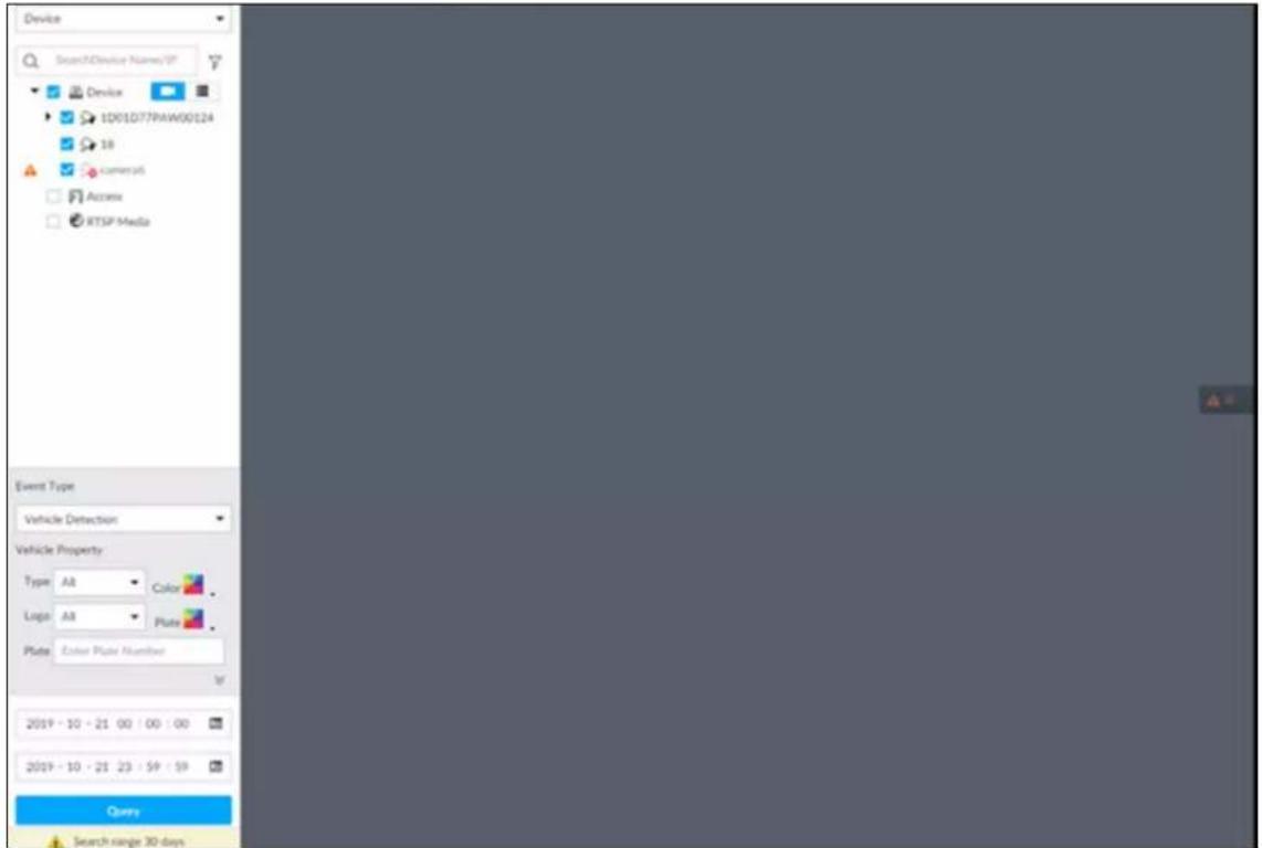
Step 2 Select Vehicle Detection as Event Type.
Step 3 Set vehicle properties and time period.
Click or to set the color. means more than one color.
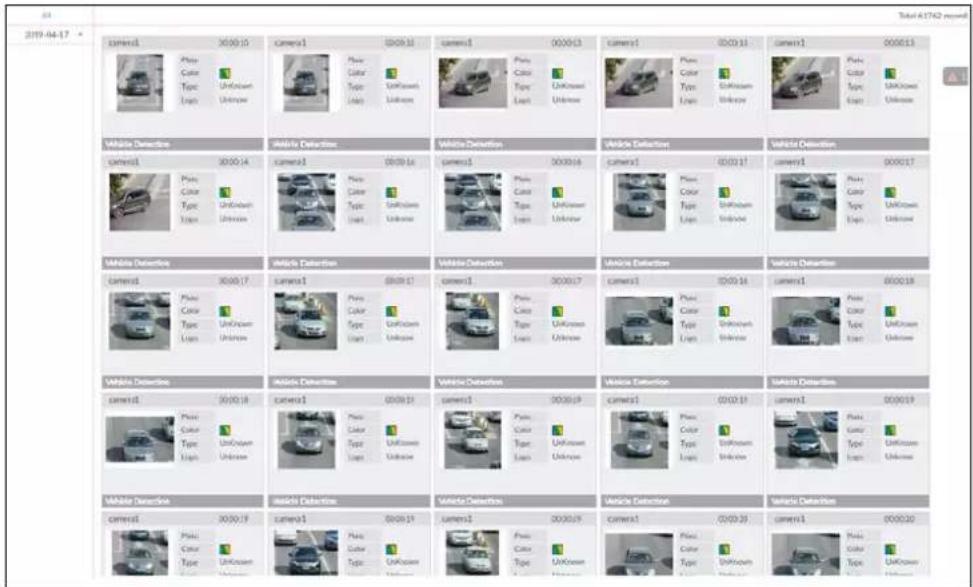
Step 4 Click Query.
If license plate is detected, both the scenario and the license plate will be displayed.
Figure 4-28 Search result
Related Operations
Point to one displayed panel, and the icons are displayed.
Figure 4-29 Icons
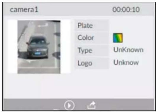
Table 4-6 Operation
| Icon Operation | |
| Select one by one: Click to select the panel.means the panel is selected.Select in batches: Select All to select all the panels on the page. | |
| Click or double-click the panel to play back the video record (10 s before and after the snapshot). | |
| Click , or select the panel and then click to export picture, video, and Excel file to specified saving path. |
4.4.4.3 Non-motor Vehicle Search
Set event type and non-motor vehicle properties to search non-motor vehicle detection results.
Procedure
Step 1 Click + and then select AI SEARCH > Search by NonMotor.
Figure 4-30 Search by non-motor vehicle
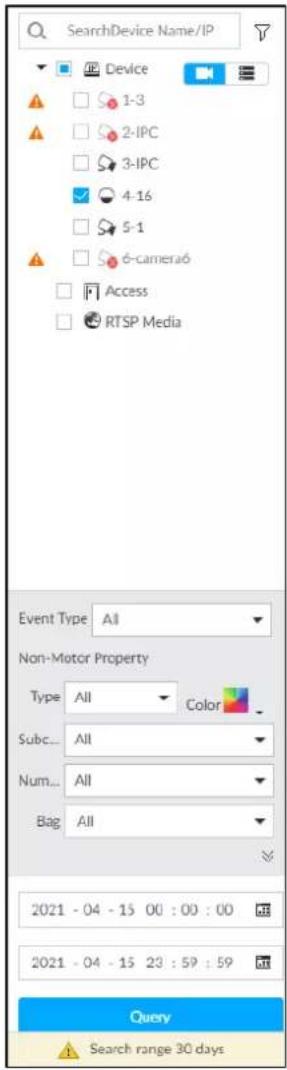
Step 2 Select the Device you want to search.
Step 3 Set non-motor vehicle properties and time period.
Click or to set the color. means more than one color.
Step 4 Click Query.
Figure 4-31 Search results
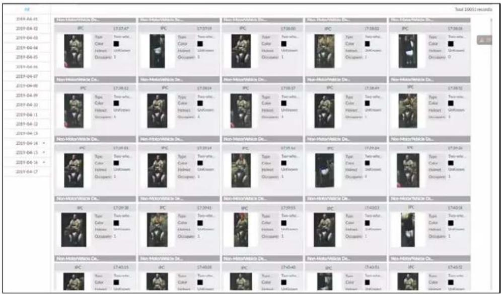
Related Operations
Point to one displayed panel, and the icons are displayed.
Figure 4-32 Icons
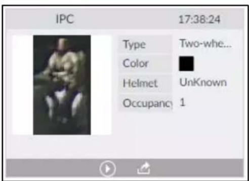
Table 4-7 Operation
| Icon Operation | |
| [0H6H] | Select one by one: Click to select the panel.means the panel is selected.Select in batches: Select All to select all the panels on the page. |
| [X208] | Click or double-click the panel to play back the video record (10 s before and after the snapshot). |
| [X94T] | Click, or select the panel and then click to export picture, video, and excel file to specified saving path. |
4.5 IVS
The IVS feature includes a number of behavior detections such as fence-crossing, intrusion, tripwire, parking, crowd gathering, missing object, abandoned object, and loitering. You can configure alarm notifications of those intelligent detections.
This section introduces how to configure the intelligent detections.

- For the same camera, IVS and face detection cannot be enabled at the same time.
• Some device models only support IVS by camera.
4.5.1 Enabling AI Plan
Enable AI plan when AI by Camera is used. See "4.1.1 Enabling AI Plan" to enable AI detect function.
4.5.2 Configuring IVS
4.5.2.1 Global Configuration
Configure global rules of IVS, including anti-disturbance and sensitivity settings.
Step 1 Click 🎨 or click + on the configuration page, and then select EVENT.
Step 2 In the device tree, select a camera.
Step 3 Select AI Plan > IVS > Global Config.
Figure 4-33 Global config
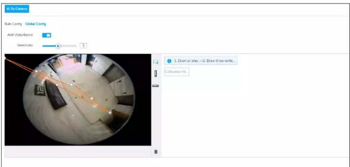
Step 4 Configure anti-disturbance and sensitivity settings.
- Click □ to enable anti-disturbance function.
- Drag to adjust sensitivity.
Step 5 Calibrate horizontal and vertical scales.
1) Click to draw an area.
2) Click ☐ to draw three vertical lines, enter the actual length, and then click Calibration Verification.
3) Click ☐ to draw a horizontal line, enter the actual length, and then click Calibration Verification.
Step 6 Click Save.
4.5.2.2 Rule Configuration
Configure rules of IVS functions such as fence-crossing, tripwire, intrusion, abandoned object, parking detection, people gathering, object removed, and loitering. Different cameras support different functions.
Table 4-8 IVS functions description
| Functions Description | |
| Fence-crossing | Alarm is triggered when a target is crossing the pre-defined fence. |
| Tripwire | Alarm is triggered when a target is crossing the pre-defined tripwire. |
| Intrusion | Alarm is triggered when a target is entering, leaving, or appears in the detection area. |
| Abandoned Object | Alarm is triggered when an object is left in the detection area and the existence time is longer than the threshold. |
| Missing Object | Alarm is triggered when an object is removed from the detection area and not put back after the pre-defined time period. |
| Parking Detection | Alarm is triggered when a target remains still within a time period longer than the pre-defined time duration. |
| People Gathering | Alarm is triggered when people gathering is detected or people density is larger than the threshold. |
| Loitering | Alarm is triggered when a target keeps loitering in a time period longer than the threshold. Alarm will be triggered again if the target stays in the detection area after the first alarm. |
Take tripwire as the example. The configuration procedure is as follows.
Step 1 Click 🎨, or click + on the configuration page, and then select EVENT.
Step 2 Select remote device in the device tree on the left.
Step 3 Select AI Plan > IVS.
Figure 4-34 Add rules
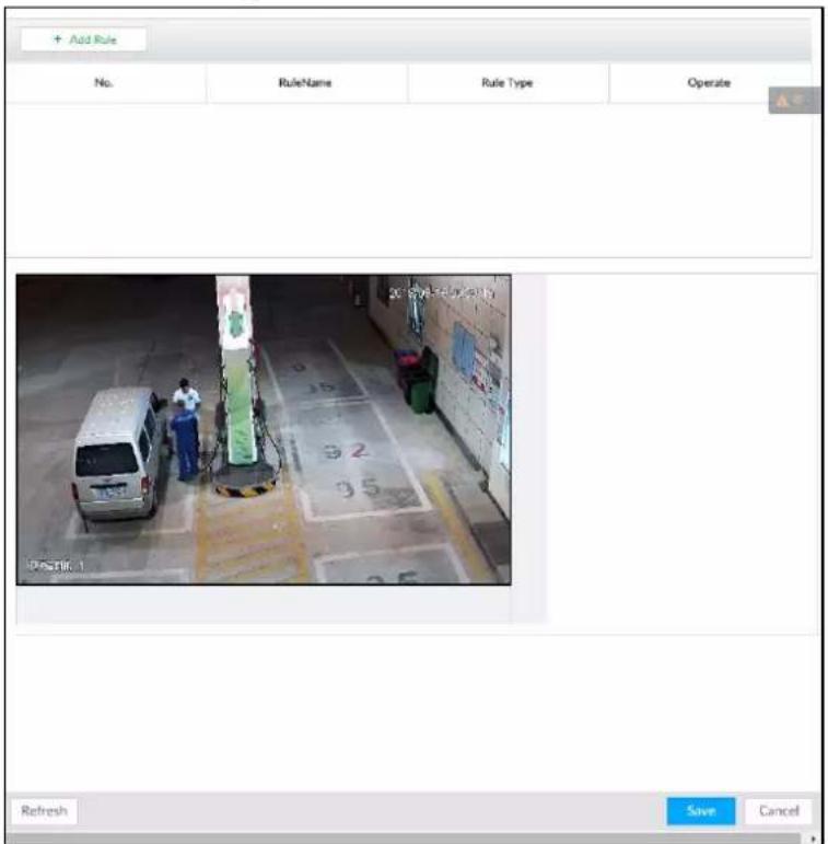
Step 4 Set tripwire rules.
1) Click Add Rule, and then select Tripwire.
Figure 4-35 Configuring tripwire detection rules
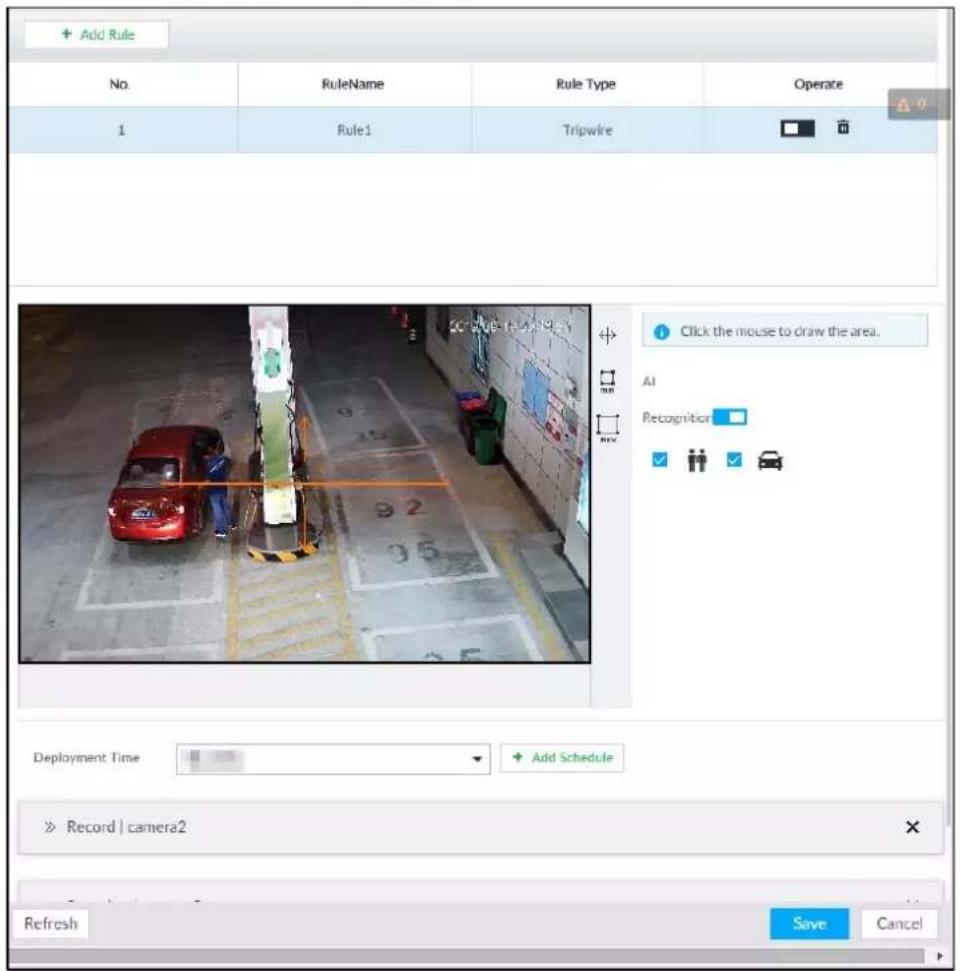
2) Click □ to enable detection rule.
Click to delete detection rule.
3) Click to edit the tripwire line.
- Drag ✗ to adjust position or length of the line.
- Click ☐ or ☒ to set the directions. An alarm will be triggered only when the target crosses the line in the designated direction.
- Click the white dot on the line to add a turning point. Drag ✗ at the turning point to adjust position or length.
4) Click min or max to set minimum size or maximum size of detection target.
System triggers an alarm once the detected target size is between the maximum size and the minimum size.
Step 5 (Optional) Set other requirements.
Table 4-9 IVS rules configuration requirements
| Functions Description | |
| Fence-crossing | Draw 2 detection lines.Transparent fences such as iron fence are not supported.Extremely short walls (height lower than normal height) are not supported. |
| Tripwire Draw 1 detection line. | |
| Intrusion | Draw 1 detection line.With the abandoned object detection, a person or vehicle that stays still for a long time will also trigger an alarm; if the object is smaller than human or vehicle, you can set the target size to filter out people and cars, or extend the minimum lasting duration to avoid false alarms caused by short dwell of people.For the crowd gathering detection, if the installation height is too low, human body size will take a large proportion in the image, or the camera view might be blocked. That might result in false alarms caused by continuous shaking of the camera, shaking leaves, frequent door opening and closing, and dense traffic of vehicles and people. |
| Abandoned Object | |
| Missing Object | |
| Parking Detection | |
| Crowd Gathering | |
| Loitering | |
Step 6 Set AI Recognition.
After setting AI recognition, when the system detects a person, vehicle or non-motor vehicle, a rule box will appear beside the target on the video.
1) Click □ to enable AI recognition function.
Figure 4-36 Type
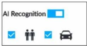
2) Select a recognition type.
• is to recognize human, and is to recognize vehicle.
- After enabling AI recognition function, at least one recognition type shall be selected.
Step 7 Click Deployment Time to select schedule from the drop-down list.
After setting deployment period, system triggers corresponding operations when there is a motion detection alarm in the specified period.
- Click View Schedule to view detailed schedule settings.
- If the schedule is not added or the added schedule does not meet actual needs, click Add Schedule.
Step 8 Click Actions to set alarm action. See "6.4.1 Alarm Actions" for detailed information.

Repeat Step 4-Step 8 to add multiple detection rules. You can add max. 10 detection rules at the same time.
Step 9 Click Save.
4.5.3 Live View of IVS
On the LIVE page, view real-time IVS results.
4.5.3.1 Setting AI Display
Set the display rules of detection results.

Make sure that view is created before setting AI display. To create view, see "5.1.1 View Management".
Step 1 Select a view from LIVE > View > View Group.
Step 2 Click , and then select the Human or Vehicle tab.
Figure 4-37 Human
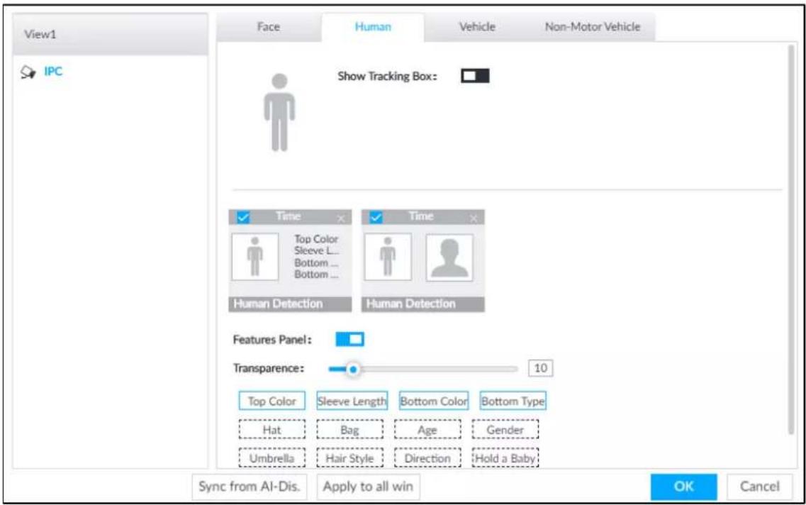
Figure 4-38 Vehicle
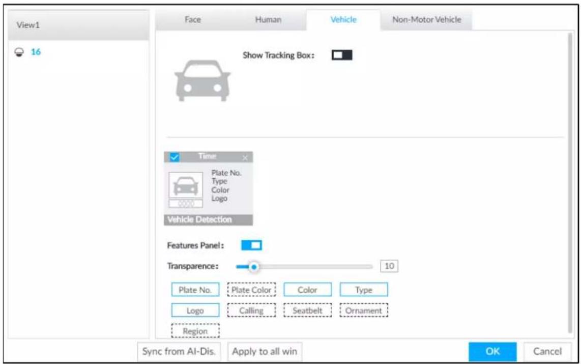
Step 3 Click next to Show Tracking Box.
Step 4 Configure feature panel.
1) Click next to Features Panel to enable feature panel.
A features panel is displayed on the right side of the video when a target that meets the conditions is detected.
2) Click □ to select the panel type, for example, the Human Detection tab.
3) (Optional) Drag to adjust the transparency of panel. The higher the value, the more transparent the panel.
4) (Optional) Select the features to be displayed in the panel.
• Up to 4 features can be displayed.
- 4 features are selected by default. To select another feature, click the selected feature to cancel it, and then click the feature to be displayed.
Step 5 Click OK.
4.5.3.2 Live View
Go to the LIVE interface, enable view, and then Device displays view video.
- When a target triggers cross line or cross region rule, the line or region frame in the view flickers in red.
- After setting AI recognition, when the system detects a person or vehicle, a rule frame will appear beside the person and vehicle in the view.
- There is a feature panel on the right side of the video window.
Figure 4-39 Live
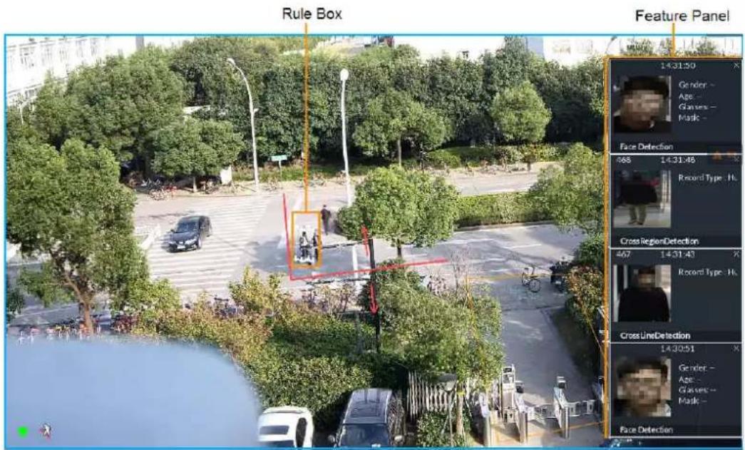
Point to features panel, and the operation icons are displayed. Click 📋 or double-click the detected image, so the system starts to play back the recorded videos (10 s before and after the snapshot).
4.5.3.3 Detection Statistics
On the LIVE page, click 🎯. The PEOPLE TOTAL page is displayed. Click 🎯, and then select IVS. The people detection records are displayed.
Figure 4-40 People total
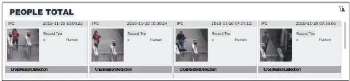
Click 📄. The VEHICLE TOTAL page is displayed. Click 🔒, and then select IVS. The detected vehicles are displayed.
Figure 4-41 Vehicle total
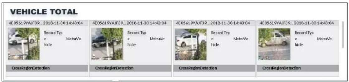
- Point to a picture and click 📋, or double-click the picture, so the system starts playing back video (10 s before and after the snapshot moment).
- Point to a picture and click 📋 to export video.
On the LIVE page, click 📁. The NONMOTOR TOTAL page is displayed. Click 📋, and then select IVS. The detected non-motor vehicles are displayed.
- Point to a picture and click 📋, or double-click the picture, so the system starts playing back video (10 s before and after the snapshot moment).
- Point to a picture and click 📋 to export video.
4.5.4 IVS Search
Search for IVS records.
Step 1 Click + and then select AI SEARCH > IVS.
Figure 4-42 IVS
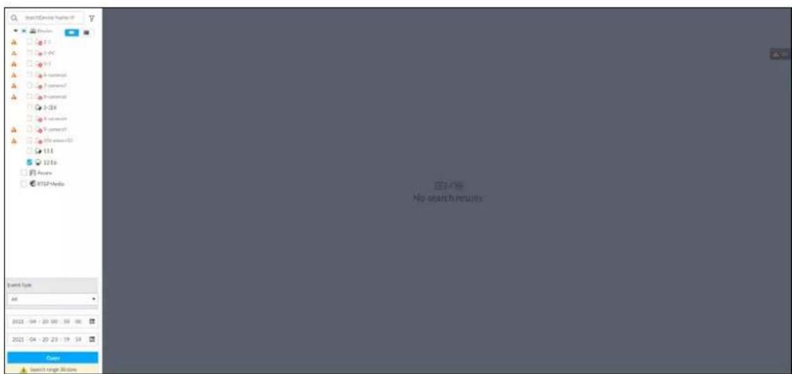
Step 2 Select the remote device, and set event type and time.
Step 3 Click Query.
Figure 4-43 Search result
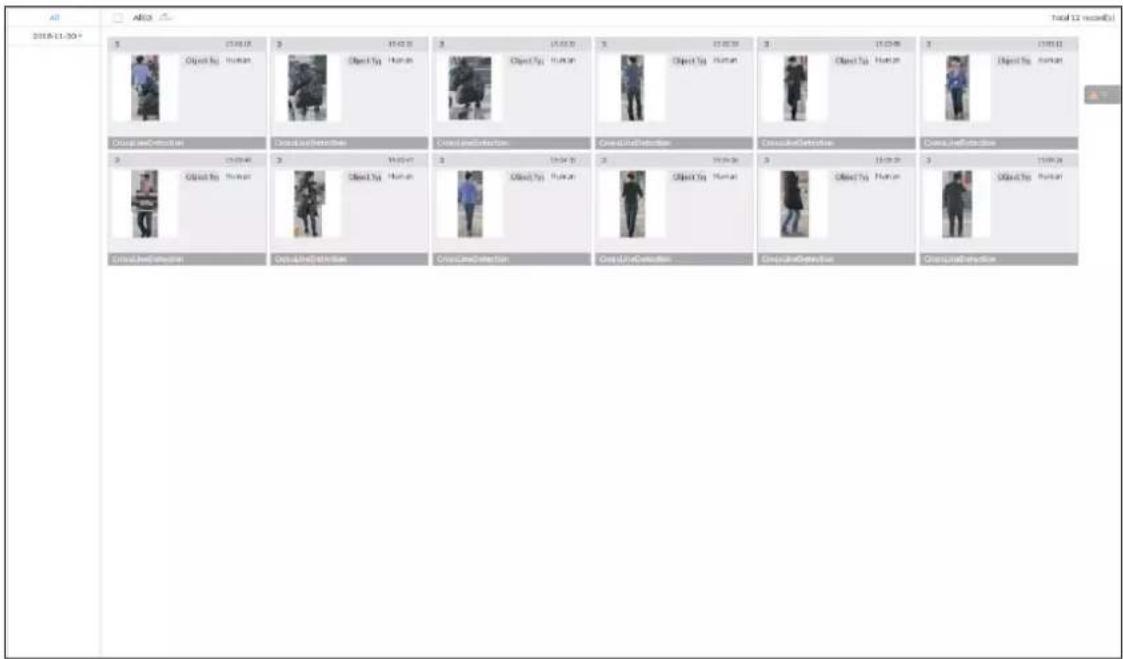
Click the panel. The following operation icons are displayed.
Table 4-10 More operations
| Name Operation | |
| Select a panel | Select one by one: Move the mouse onto the panel. Click □ to select the panel. ≈ means it is selected.Click ALL to select all the panels. |
| Playback | Click the panel, and click ▶ or double-click the panel. The system starts to play back the recorded videos (10 s before and after the snapshot). |
| Export file | Click the panel and click ▶, or click the panel and click ↗ to export images, videos and Excel to designated storage path.▲After setting alarm linkage snapshot, during exporting images, the system exports detected images and panoramic images at the time of snapshot. |
4.6 Vehicle Recognition
Alarm is triggered when vehicle property that meets detection rule is detected.

EVS supports only vehicle recognition through AI by Camera. Make sure that the vehicle recognition parameters of camera are configured. For details, see the user's manual of the camera.
4.6.1 Enabling AI Plan
Before using AI by Camera, AI plan needs to be enabled first. For details, see "4.1.1 Enabling AI Plan".
4.6.2 Setting Vehicle Recognition
Set the deployment time of vehicle recognition and alarm linkage event.
Step 1 Click 🎨 or + , and then select EVENT.
Step 2 Select device from the device tree at the left side.
Step 3 Select AI Plan > Vehicle Recognition.
Figure 4-44 Vehicle recognition
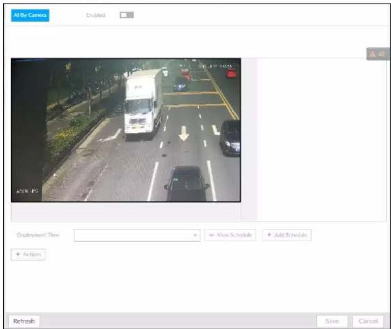
Step 4 Click the Deployment Time drop-down list to select schedule.
EVS links alarm event when alarm is triggered within the defined schedule.
- Click View Schedule to view detailed schedule settings.
- If the schedule is not added or the added schedule does not meet actual needs, click Add Schedule. For details, see "6.9.3 Schedule".
Step 5 Click Actions to set alarm action. For details, see "6.4.1 Alarm Actions".
Step 6 Click Save.
4.6.3 Live View of Vehicle Recognition
View vehicle recognition results on the LIVE page.
4.6.3.1 Setting AI Display
Set the display rules of detection results.

Make sure that view is created before setting AI display. To create view, see "5.1.1 View Management".
Step 1 Select a view from LIVE > View > View Group.
Step 2 Click , and then select Vehicle tab.
Figure 4-45 Motor vehicle
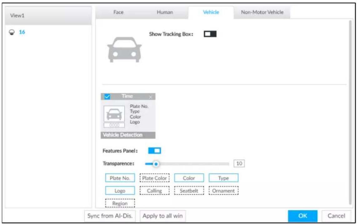
Step 3 Click next to Show Tracking Box to enable tracking box function.
A tracking box is displayed in the video image when target meeting detection rule is detected. Step 4 Set features panel.
1) Click □ next to Features Panel to enable features panel function.
Features panel will be displayed at the right side of video image when target with selected features is detected.
2) Select the Vehicle Detection panel type by clicking ☐. √ means the panel is selected.
3) (Optional) Drag to adjust the transparency of panel. The higher the value, the more transparent the panel.
4) (Optional) Select the features to be displayed in the panel.
• Up to 4 features can be displayed.
- 4 features are selected by default. To select another feature, click the selected feature to cancel it, and then click the feature to be displayed.
Step 5 Click OK.
4.6.3.2 Live View
On the LIVE page, select a view, and the video image of the view is displayed.
- Tracking box is displayed in the video image.
● Features panel is displayed at the right side of the video image.
Figure 4-46 Live
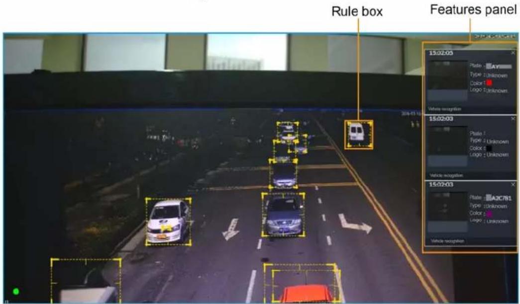
Move the mouse pointer to the features panel, and then you can click 📋 or double-click the vehicle image to play back the video image (10 s before and after the snapshot).
4.6.3.3 Detection Statistics
On the LIVE page, select a view and then click 📄. The VEHICLE TOTAL page is displayed.
Click 📋, and then select Vehicle Detection. The information of detected vehicles is displayed.
Figure 4-47 Vehicle detection
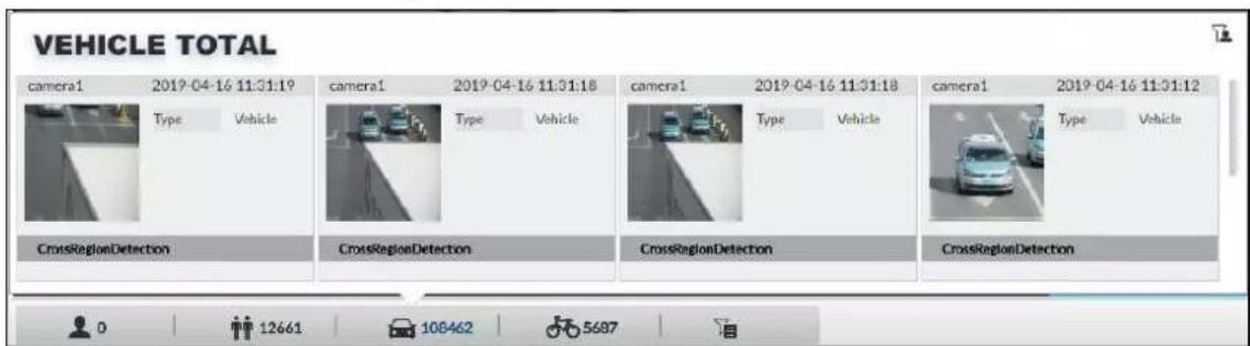
- Move the mouse pointer to the information panel, and then click 📋 or double-click the picture to play back the video image (10 s before and after the snapshot).
- Move the mouse pointer to the information panel, and then click 📋 to export the video to specified saving path.
4.6.4 Searching for Detection Information
Set event type and vehicle properties, and then search vehicle detection information. For details, see "4.4.4.2 Vehicle Search".
4.7 Crowd Distribution Map
View and monitor people crowd to avoid crowd incidents, for example, stampede.

This function is only available with AI by Camera.
4.7.1 Enabling AI Plan
Enable the corresponding AI plan before using AI by Camera functions. For details, see "4.1.1 Enabling AI Plan".
4.7.2 Configuring Crowd Distribution Map
Set crowd distribution alarm rules.
4.7.2.1 Global Configuration
Draw lines on the image to determine the geographical scale of the image.
Step 1
Click

or click

on the configuration page, and then select EVENT.
Step 2
In the device tree, select a camera.
Step 3
Select AI Plan > Crowd Distribution Map > Global Config.
Figure 4-48 Global config
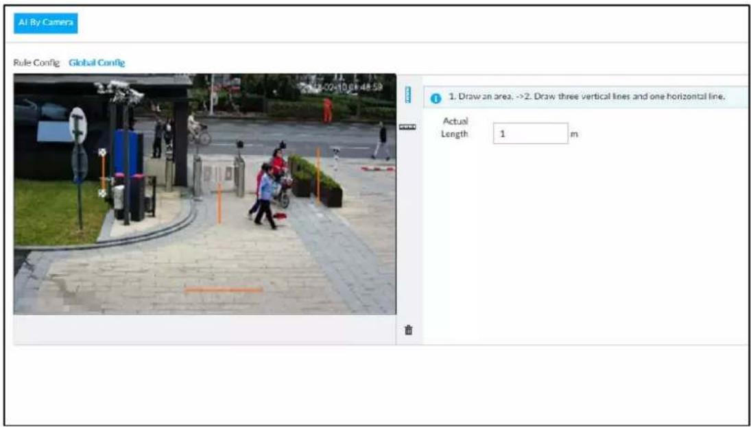
Step 4 Draw lines. Draw one horizontal line and three vertical lines.
- Click ☐, draw vertical lines, and then enter their geographical distance values.
- Click , draw a horizontal line, and then enter the geographical distance value.
Step 5 Click Save.
4.7.2.2 Rule Configuration
Configure the alarm threshold for crowd monitoring. For example, when the crowd density reaches 8, an alarm is triggered.
Step 1 Click 🎨 or click + on the configuration page, and then select EVENT.
Step 2 In the device tree, select a camera.
Step 3 Select AI Plan > Crowd Distribution Map > Rule Config.
Step 4 Click next to Enabled to enable rule configuration.
Step 5 Set detection rules.
- Set regional detection rules.
1) Click Add Rule. The following page is displayed.
Figure 4-49 Add Rules
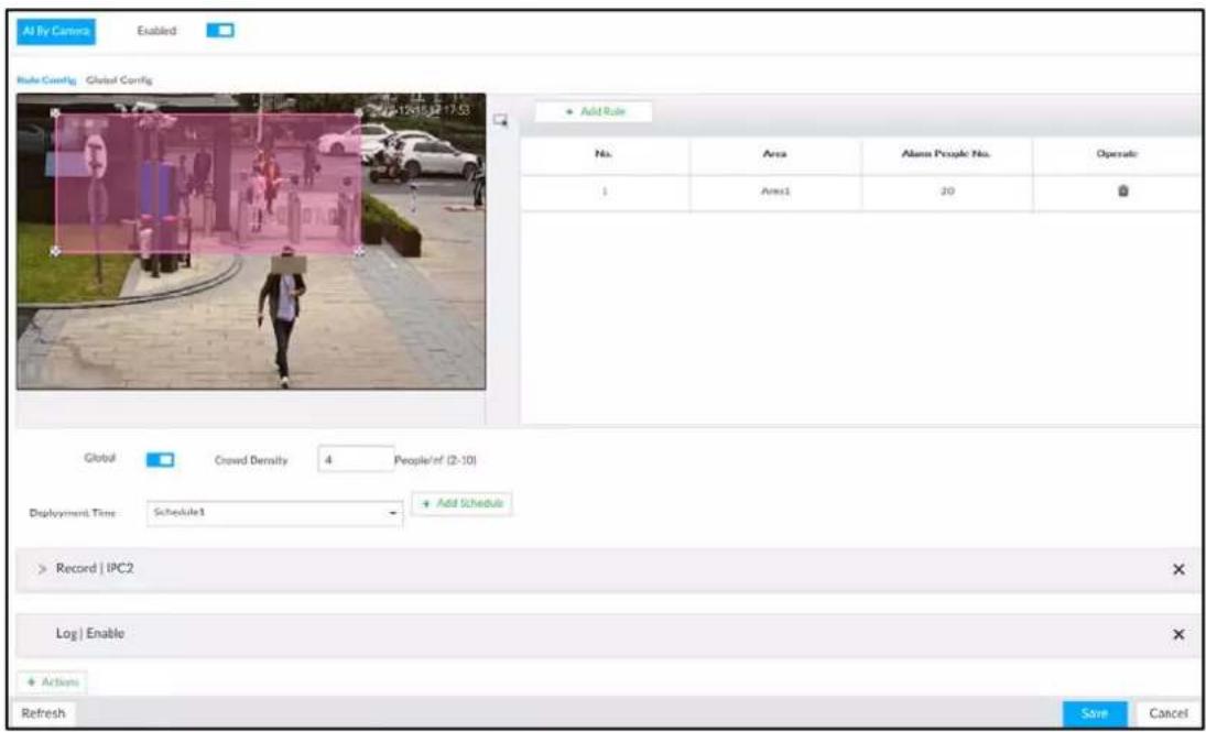
2) Drag ✗ to adjust the size.
3) Configure alarm threshold. Alarm is triggered when the detected people number reaches the threshold.
- Set global alarm.
1) Click , and then drag ✗ to adjust the size of the yellow area.
2) Click □ to enable global detection.
3) Set crowd density. Alarm is triggered when the detected crowd density reaches the threshold.
Step 6 Select a schedule from the Deployment Time drop-down list.
The alarm linkage action is triggered only during the scheduled period.

To modify the schedule, click Add Schedule.
Step 7 Click Actions, and then select an action to be associated to the alarm.
Step 8 Click Save.
4.7.3 Live View of Crowd Distribution
On the LIVE page, open a view that contains the crowd distribution detection camera.
The video shows people numbers in the detection areas in real time. The area frame flashes red when there is an alarm in the area.
Figure 4-50 Live view of crowd distribution
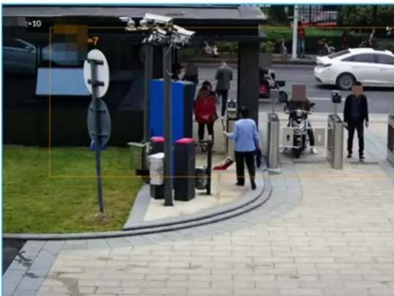
natural_image
Street scene with pedestrians near a modern bus stop and sidewalk, no visible text or symbols- Right-click on the live video, and then select Crowd Distribution Map > PIP. A blue section is displayed, and it shows the crowd distribution status inside the current view.
- Right-click on the live video, and then select Crowd Distribution Map > Global to switch to the distribution view. The view indicates crowd density and people heads in different colors.
4.8 Call Alarm
An alarm is triggered when the system detects a person calling. To configure call alarm, set call detection rules for the visible light channel of a thermal camera.

Call alarm is only available with AI by Camera.
4.8.1 Enabling AI Plan
Enable the corresponding AI plan before using AI by Camera functions. For details, see "6.2.1 Enabling AI Plan".
4.8.2 Configuring Call Alarm
Configure call alarm rules.
Step 1 Click 🎨 or click + on the configuration page, and then select EVENT.
Step 2 In the device tree, select the visible light channel of a thermal camera.
Step 3 Select AI Plan > Call Alarm.
Step 4 Click next to Enabled to enable rule configuration.
Figure 6-106 Configure call alarm
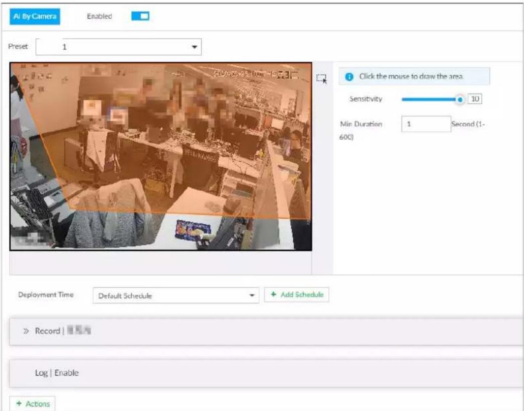
Step 5 Click and drag ✗ to adjust the size of the detection area (yellow area).
Step 6 Set Sensitivity and Min Duration.
- Sensitivity: The higher the Sensitivity is, the easier the call action is detected.
- Min Duration: The minimum duration the call action lasts. If the call action still lasts after the Min Duration, the system will trigger an alarm.
Step 7 Click Deployment Time to select a schedule from the drop-down list.
System triggers corresponding alarm actions only during the alarm deployment period.

You can select an existing schedule from the Deployment Time drop-down list. You can also add a new schedule. For details, see "8.9.4 Schedule".
Step 8 Click Action to set alarm action. See "8.4.1 Alarm Actions" for detailed information.
4.8.3 Live View of Call Alarm
Log in to PCAPP. On the LIVE page, open a view that contains the call alarm detection channel. The call action is highlighted in red when the alarm is triggered.
Figure 6-107 Live view of call alarm
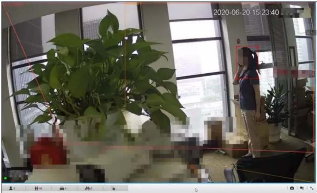
4.9 Smoking Alarm
An alarm is triggered when the system detects a person smoking. To configure smoking alarm, set smoking detection rules for the visible light channel of a thermal camera.

Smoking alarm is only available with AI by Camera.
4.9.1 Configuring Smoking Alarm
Configure smoking alarm rules.
Step 1 Click 🎨 or click + on the configuration page, and then select EVENT.
Step 2 In the device tree, select the visible light channel of a thermal camera.
Step 3 Select AI Plan > Smoking Alarm.
Step 4 Click next to Enabled to enable rule configuration.
Figure 6-109 Configure smoking alarm
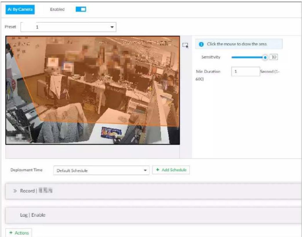
Step 5 Click and drag ✗ to adjust the size of the detection area (yellow area).
Step 6 Set Sensitivity and Min Duration.
- Sensitivity: The higher the Sensitivity is, the easier the call action is detected.
- Min Duration: The minimum duration the call action lasts. If the call action still lasts after the Min Duration, the system will trigger an alarm.
Step 7 Click Deployment Time to select a schedule from the drop-down list.
System triggers corresponding alarm actions only during the alarm deployment period.

You can select an existing schedule from the Deployment Time drop-down list. You can also add a new schedule. For details, see "8.9.4 Schedule".
Step 8 Click Actions to set alarm action. See "8.4.1 Alarm Actions" for detailed information.
4.9.2 Live View of Smoking Alarm
Log in to PCAPP. On the LIVE page, open a view that contains the smoking alarm detection channel. The smoking action is highlighted in red when the alarm is triggered.
5 General Operations
This chapter introduces general operations such as live view, playback, alarm, AI functions, and IVS.
5.1 Live and Monitor
Click +, and then select LIVE. The LIVE page is displayed.

Move the mouse pointer to the middle of video window and left column. is displayed. Click the
icon to hide the left column. See Figure 5-2.
Figure 5-1 Live (1)
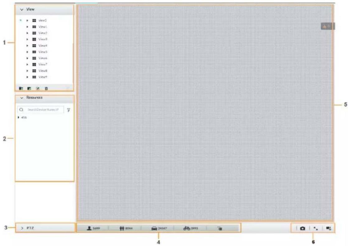
Figure 5-2 Live (2)
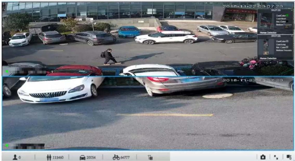
Table 5-1 Live page description
| No. Description | |
| 1 | View zone. Displays the created view and view group. See "5.1.1 View Management" for detailed information. |
| 2 | Resource pool. Displays the added remote device list. |
| 3 PTZ zone. | |
| 4 | Smart preview icons. View face statistics, person statistics, IVS statistics and AI display. |
| 5 | Video play window. See "5.1.1.3 View Window". |
| 6 | Click to take snapshot.Click for full-screen view.Click to go to theVIDEO RECORDINGpage for recording configuration. |
5.1.1 View Management
View is composed of video images of several remote devices. Go to the view panel at the upper-left corner of the LIVE page to view or call the view. See Figure 5-3.
- System has created views by default. Create view or view group under the View.
- Double-click a view or drag the view to the play panel on the right side. Device begins playing the real-time video from the remote device.
- Click ☐ to select views and its sub-node.
Figure 5-3 View
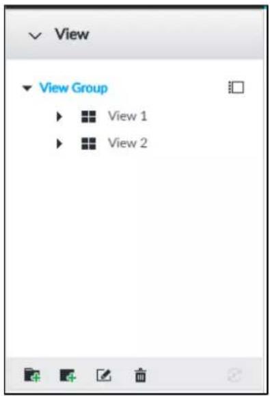
5.1.1.1 View Group
View group is a group of views. The view group allows you to categorize and manage view. It is easy for you to search and find the view. Create view or view group under the View.

• Device supports maximum 100 view groups.
- The views hierarchy shall not be more than 2. For example, after you create View Group 1 under View, you can create a sub-level View Group 2 under View Group 1. However, you cannot create sub-level group under View Group 2.
Procedure
Step 1 Follow the steps listed below to create a view group.
- Click View Group or a created view group, and then click
- Right-click View Group or a created view group, and then select Add View Group. System creates one view group.

Figure 5-4 Create view group
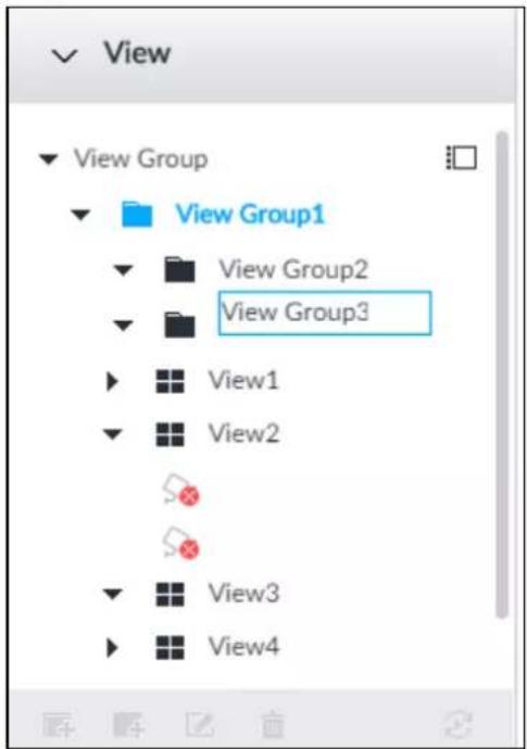
Step 2 Set view group name.
- The view group name ranges from 1 to 64 characters. It can contain English letters, numbers and special characters.
- View group is to classify different view groups. We recommend the view group name shall be easy to recognize.
Step 3 Click any blank space on the page.
Device pops up a prompt of success.
Related Operations
After creating view group, view group can be renamed or deleted. See Table 5-2 for detailed information.
Table 5-2 View group
| Name Operation | |
| Rename view group | Select a view group and then click. Set view group name and click any spare panel.Right-click view group and selectRename.See Figure 5-5. Set view group name and click any spare panel. |
| Delete View group | Once you delete view group, all views under current view group will be deleted at the same time. Please be careful!Select view group and clickRight-click view group and then selectDelete. |
Figure 5-5 Rename
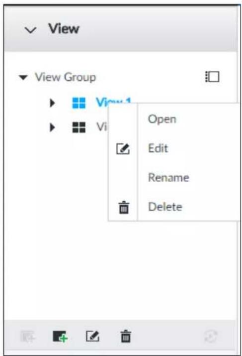
5.1.1.2 View
View is a video component of several remote devices. You can drag several remote devices to the same view and when view function is enabled, you can view the real-time video from several remote devices at the same time.
5.1.1.2.1 Creating View
Creating view is to add several associated remote devices to the same View. It is easy to view the real-time video from several remote devices at the same time.
Preparation
Remote device has been added. See "3.4.2 Adding Remote Device" for detailed information.
Create View
Step 1 Follow the steps listed below to create view.
- Select a view group, click 📄, and then select Add view.
• Right-click a view group, and then select Add view.
Figure 5-6 Edit view (1)
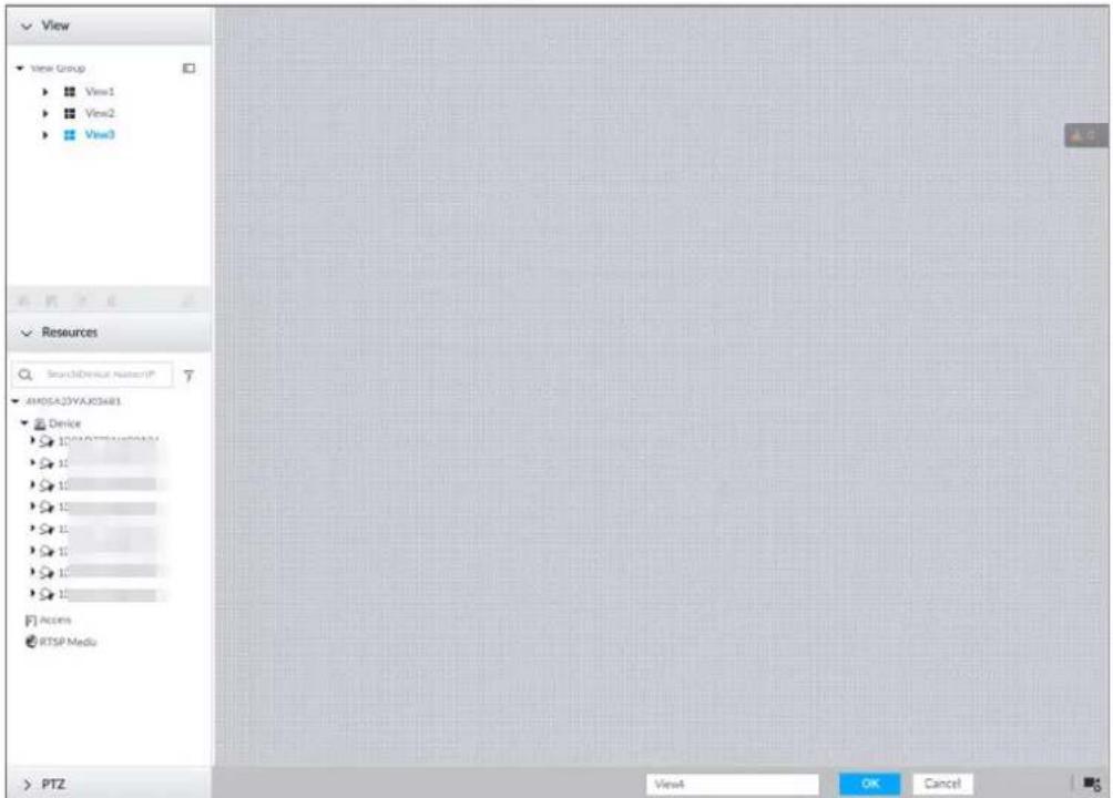
Step 2 Double-click a remote device in resource pool, or drag the remote device to the right panel. After one remote device is added, layout grid is displayed.
- Each layout grid supports one remote device. If you want to add several remote devices, drag the rest remote device to other idle layout grid.
- If the layout grid has added the remote device, drag another remote device to current grid to replace the original one.
- Move the mouse pointer to the orange panel (such as 📄) of the view window, click the view window, and then drag after you see the arrow icon to adjust view window size.

- Device automatically creates the view grids amount according to the selected remote device amount. Device supports maximum 36 view windows.
- The view window fills in the whole layout grid by default. Right-click to select Original Scale > ON, and turn on the Original Scale. The device automatically adjusts view window size according to resolution of remote device.
- When adjusting view window position, drag the view window to the layout grid of the green background color. You cannot drag the view window to the grid of red background color.
Figure 5-7 Edit view (2)
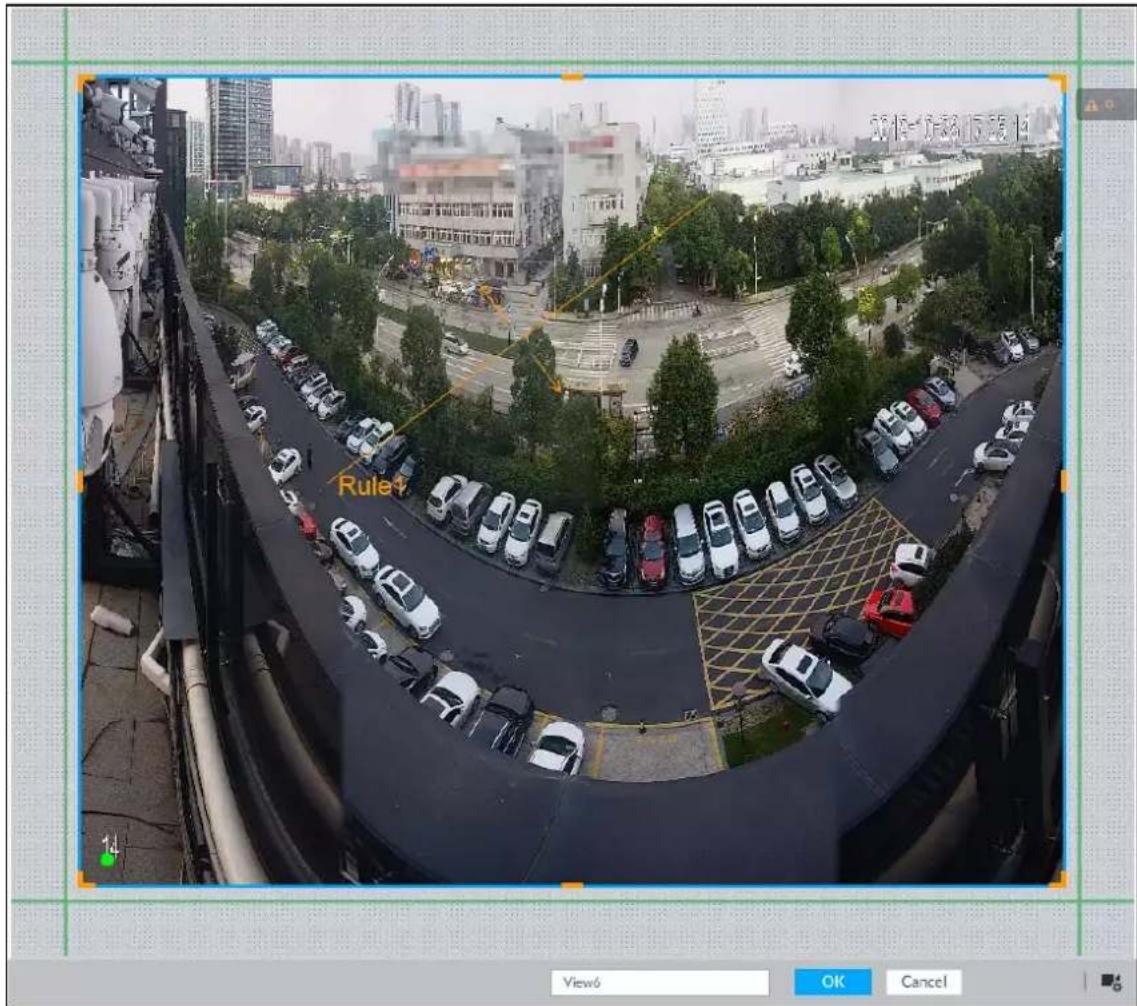
Step 3 Set view name.
The view name ranges from 1 to 64 characters. It can contain English letters, number and special character.
Step 4 Click OK to save the configuration.
Device pops up a prompt of Successfully operated.
Related Operations
After creating view, view can be edited, enabled, renamed or deleted.
Table 5-3 View
| Name Operation | |
| Edit View | Edit remote device in the view, window layout and view name. See "5.1.1.2.2 Editing View" for detailed information. |
| Enable view | After enabling view, view real-time image of remote device in the view. See "5.1.1.2.3 Enabling view" for detailed information. |
| Rename view | Select a view group and then click . Set view group name and click any spare panel.Right-click view and select Rename. See Figure 5-8. Set view name and click any spare panel. |
| Delete view | Delete: Select a view and then click , or right-click view and then select Delete.Batch delete: Click , select views you want to delete and then click. |
Figure 5-8 Menu
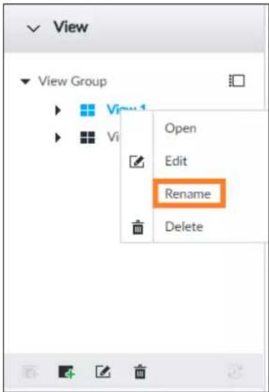
5.1.1.2.2 Editing View
In edit view mode, you can perform the following functions:
- Add, or delete the remote device on the view.
- Adjust the view grid display.
- Modify view name.
Step 1 Right-click a view and then select Edit.
Figure 5-9 Edit view
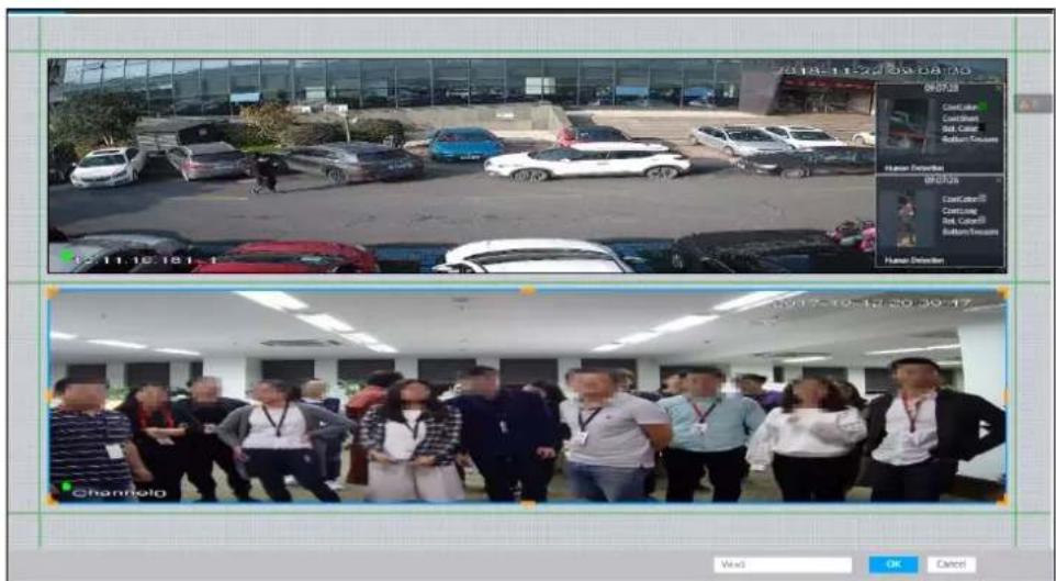
Step 2 Edit view as you require.
- Add remote device: Double-click remote device in the resource pool, or drag the remote device to the free layout grid on the right panel.
- Delete remote device: Point to window on the right, and click ✗ at the upper-right corner.
- Move window position: Select and hold on a view window, move it to the proper position and release mouse.
- Change window position: Select and hold on one view window and then drag to another view window.
- Change window size: Move your mouse to the orange panel on the window (such as

Hold and drag the view window after you see the arrow icon.
- Modify view name: Set view name on View1

When adjusting view window position, drag the view window to the layout grid of the green background color. You cannot drag the view window to the grid of red background color.
Step 3 Click OK to save the configuration.
Device pops up successfully operated.
5.1.1.2.3 Enabling view
Right-click the view and select Open, or double-click view. The view window is displayed.
Figure 5-10 View window
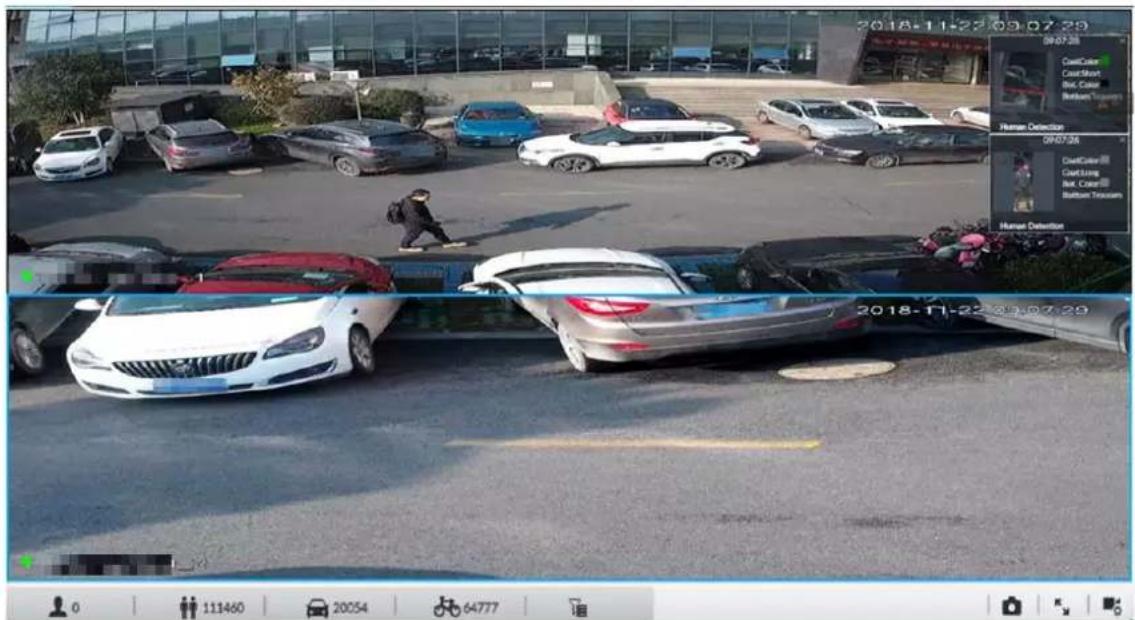
When enabling the view, you can change video position, zoom video window.

- When adjusting view window position, drag the view window to the layout grid of the green background color. You cannot drag the view window to the grid of red background color.
- Point to view window. Window task column is displayed to snapshot, enable record and turn off view window. See "5.1.1.3.1 Window Task Column" for detailed information.
- Right-click view window, you can switch bit streams, set digital zoom. See "5.1.1.3.2 Shortcut Menu" for detailed information.
Table 5-4 View function
| Name Description | |
| Exchange window position | Press one view window and drag it to another view window to exchange these view window position.The exchanging window position operation is valid only once. Disable and then enable view again, the view window restores original position. If you want to change view window position permanently, go to the view edit mode to set. See "5.1.1.2.2 Editing View" for detailed information. |
| Zoom in video window | ● Once current view window amount is too much (more than 9), click one view window, device displays current view window at the center of the window in the zoom in mode. Click any other blank position, you can view window restores original size.● Double-click a view window, device displays view window at one window. Double-click view window again or click any blank position, the view window restores original size. |
| Add view window | In the resource pool, double-click the remote device or drag the remote device to the right panel, you can add remote device to current view.Drag the remote device to the view window to replace the original remote device.The modified view layout is valid only for once if you do not click OK. Close and enable view again, the view layout restores original layout. |
| Close view window | Point to one view window, click × to close the view window.Close view window, device automatically adjusts view layout according to the rest remote device amount and play panel free space. |
5.1.1.3 View Window
Right-click the view, select Open, or double-click view. The view window is displayed.
Figure 5-11 View window
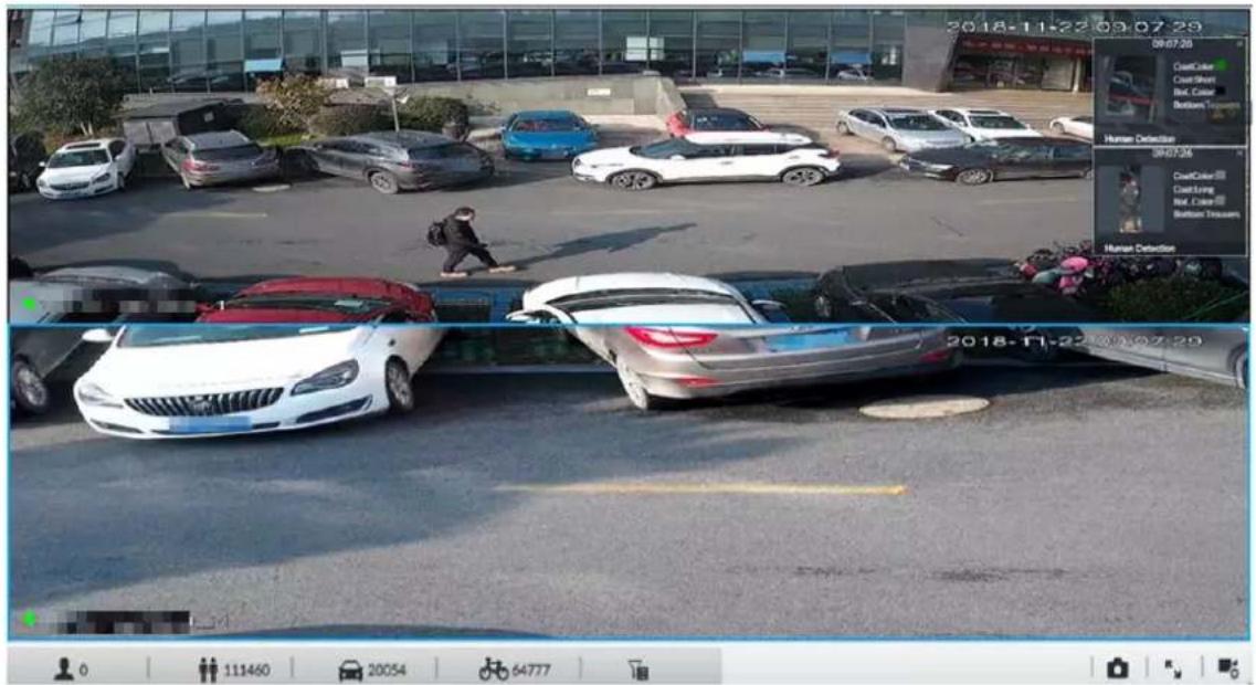
5.1.1.3.1 Window Task Column
Point to view window. The icons are displayed.
Figure 5-12 View window
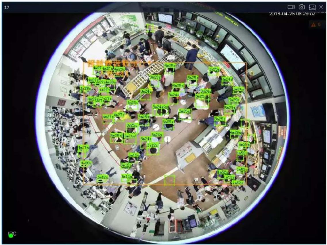
Table 5-5 Window task column
| Name Description | |
| Open Manual Video Recording | Clickto start recording manually. Now the icon becomes. Clickstop recording.System stops recording according to the manual record length settings if you donot click again to stop.At different interfaces, recording storage path varies.Local ConfigurationsWhen USB storage device is connected, recordings are saved in USB storage device.Otherwise, the recordings are saved in the Device. Query or export manual recording by playback control. See "5.2.1 Playing Back Recorded Video" for detailed information.Operate PCAPP.Default storage path of recording is C:/Program Files (x86)/EVS/video. Set storage path. |
| Snapshot | Clicksnapshot.At different interfaces, snapshot storage path varies.Local ConfigurationsWhen USB storage device is connected, snapshots are saved in USB storage device.Otherwise, the snapshots are saved in the Device. Query or export the snapshots by playback control. See "5.2.3 Playing Back Snapshots" for detailed information.Operate PCAPP.Default storage path of snapshot is C:/Program Files (x86)/EVS/pictures. Set storage path. |
| Close view window | Clickto close view window. |
5.1.1.3.2 Shortcut Menu
Right-click the view window. The shortcut menu is displayed.
Figure 5-13 Shortcut menu
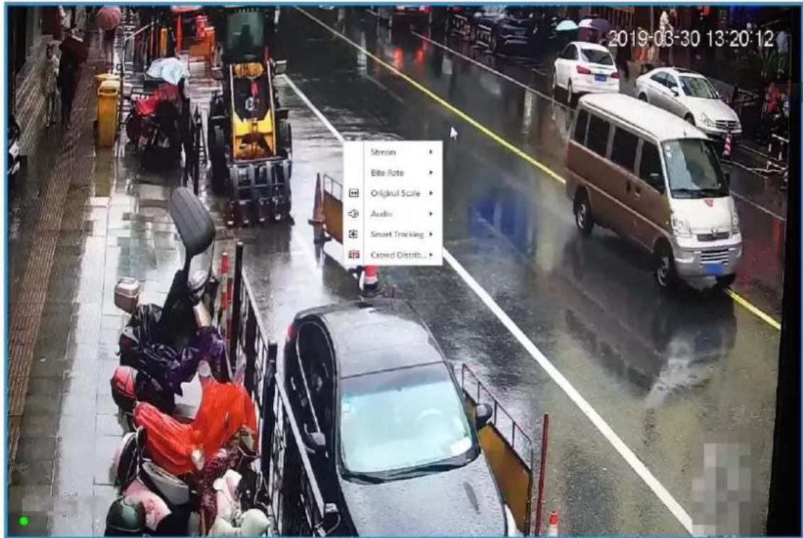
Table 5-6 Shortcut menu
| Parameters | Description |
| Stream | Set current window stream. It includes main stream/sub stream 1/sub stream 2. |
| Bit rate | Displays real-time bit rate on the window or not. See Figure 5-14. |
| Original Scale | Set video window scale.ON: System automatically adjusts video window scale according to the resolution.OFF: System automatically adjusts video window scale according to the remote device amount and the free space on the playback panel. |
| Audio | Set audio output. It includes audio 1, audio 2, mixing and off. |
| Fisheye Dewarp | Set instalaltion methods and display modes of fisheye cameras. For details, see "5.1.1.3.4 Fisheye Dewarp". This function is only available on fisheye camera. This function is only available on fisheye camera. |
| Smart tracking | Intelligently track targets. For details, see "5.1.1.3.5 Smart Tracking". This function is only available on the multi-sensor panoramic camera + PTZ camera. This function is only available on the multi-sensor panoramic camera + PTZ camera. |
| Crowd distribution | Show people numbers and distribution status. For details, see "4.7.3 Live View of Crowd Distribution". This function is only available on the camera that supports crowd distribution. This function is only available on the camera that supports crowd distribution. |
Figure 5-14 View window
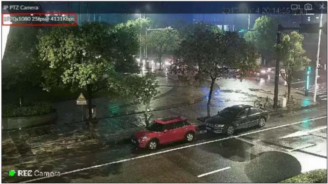
5.1.1.3.3 Digital Zoom
The digital zoom function allows you to zoom in a specified zone to view the video details.
Log in to PCAPP, double-click a view to open it, and then enable digital zoom through either of the following methods:
- Click the view, scroll the mouse to zoom in or zoom out.
- Click Ⓧ, and then select a zone you want to zoom in on the video window.
Figure 5-15 Digital zoom:
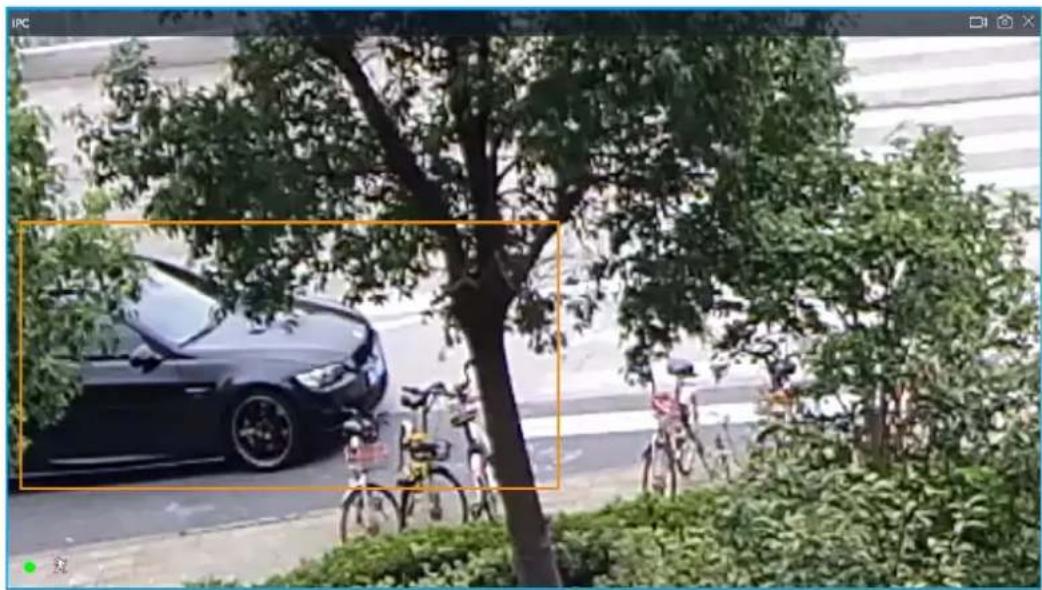
natural_image
Street scene with a parked car and bicycles under trees, no visible text or symbols5.1.1.3.4 Fisheye Dewarp
Set the installation method and display mode of fisheye cameras.
• Installation method: Select the installation method according to the actual situation.
- Display mode: Select the display mode of live view.
Step 1 Right-click on the live video, and then select Fisheye Dewarp.
Figure 5-16 Fisheye dewarp
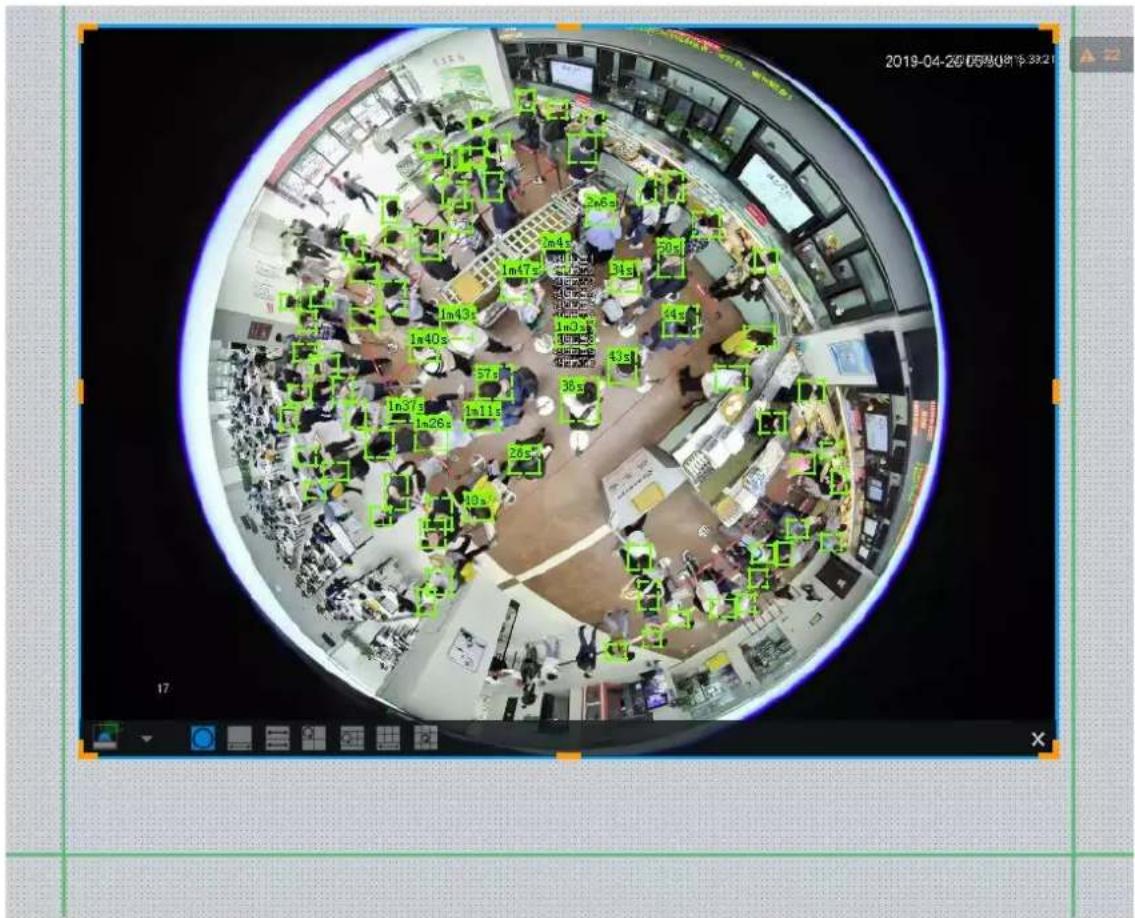
Step 2 Select an installation method.
- Click to select ceiling mount.
- Click to select wall mount.
- Click to select ground mount.
Step 3 Select a display mode.
Table 5-7 Display mode
| Installation Method | Display Mode Description | |
| Ceiling/wall/ground mount |  | The original fisheye image. |
| Ceiling/ ground mount |  1P+1 1P+1 | Corrected 360°panoramic image + section images. |
 2P 2P | 2 corrected 180°images, which consist the 360° panoramic image. | |
 1+3 1+3 | Original image + 3 section images. | |
 1+4 1+4 | Original image + 4 section images. | |
 1P+6 1P+6 | Corrected 360°panoramic image + section images. | |
 1+8 1+8 | Original image + 8 section images. | |
| Wall mount |  1P 1P | Corrected 180° image from left to right. |
 1P+3 1P+3 | Corrected 180° image + 3 section images. | |
 1P+4 1P+4 | Corrected 180° image + 4 section images. | |
 1P+8 1P+8 | Corrected 180° image + 8 section images. | |
Step 4 Click OK.
5.1.1.3.5 Smart Tracking
Track targets manually or automatically. This function is only available on the multi-sensor panoramic camera + PTZ camera.

Make sure that the linked tracking function has been enabled.
Step 1 Right-click on the live video, and then select Smart Tracking > ON.
Figure 5-17 Smart tracking
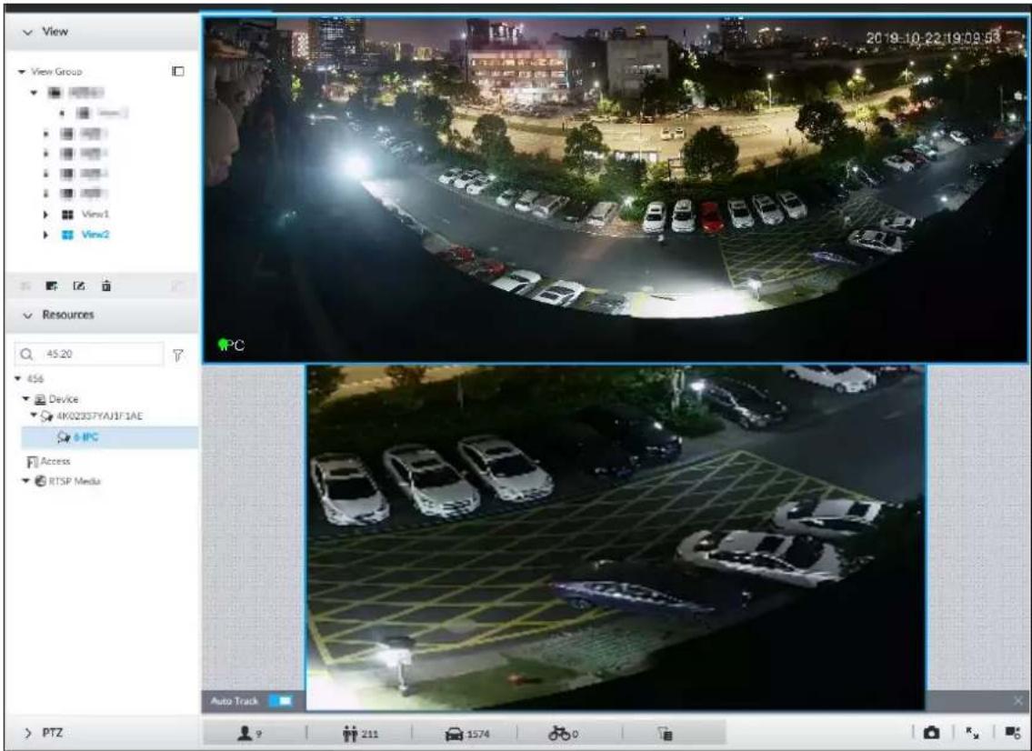
Step 2 Select the tracking method.
- Manual positioning: Click a spot or select a zone on the bullet camera video, and then the PTZ camera will automatically rotates there and zoom in.
- Manual tracking: Click or select a target on the bullet camera video, and then the PTZ camera automatically rotates and tracks it.
- Automatic tracking: The tracking action is automatically triggered by alarms in according to the pre-defined rules.

For automatic tracking, make sure that you have set intrusion detection or tripwire rules for the camera. For details, see "4.5.2 Configuring IVS".
5.1.1.3.6 Thermal
On the LIVE interface, a thermal camera has 2 channels: Visible light channel and thermal channel. Select the thermal channel, point to any position on the live video, and then you can view the real-time temperature of the position.
5.1.1.3.7 Talk
The Talk function enables voice interaction between the Device and remote devices, improving the efficiency in handling emergency events.
Step 1 Log in to PCAPP.
Step 2 Open a view on the Live page.
Figure 7-19 Talk
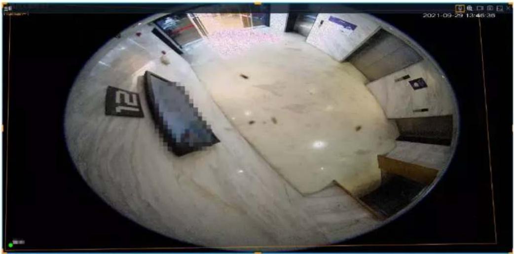
natural_image
Interior view of a modern building with large windows and minimal furniture, captured in a circular frame (no visible text or symbols)Step 3 Click ☐ at the upper-right corner of the view window to enable the Talk function. Click again to disable the function.
5.1.2 Resources Pool
The resource pool displays the added remote device list. The system automatically divides into groups according to device type.
Figure 5-19 Resources pool
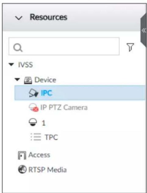
Table 5-8 Resources pool description
| Operation Description | |
| Search device | Input keywords at , device displays the corresponding remote devices.Support fuzzy search. |
| Filter device | Click ▼ and then select all, online, offline to filter the disqualified remote device. |
| View device status | Display remote device status on the resources pool.If the remote device name and icon is black, it means the remote device is online. For example, IP PTZ CameraIf the remote device name and icon is gray, it means the remote device is offline. For example, IPCIf there is an icon ▲ before the remote device, it means remote device is abnormal, alarming, and so on. Point to ▲ to view the detailed information. |
| Mouse Operations | Point to the remote device name, you can view remote device IP address and port number.On the Device list, click one remote device and then press Ctrl, click other remote device, you can select several remote devices at the same time.On the Device list, select one remote device and then press Shift, click other remote device, select current two remote devices and all remote devices listed between them.Right-click a remote device to connect to disconnect it.Double-click remote device or drag the remote device to the view window on the right panel, you can enter edit view page. Edit the view. See "5.1.1.2.2 Editing View" for detailed information. |
5.1.3 PTZ
Set PTZ functions and perform PTZ control so the PTZ camera can rotate accordingly to monitor all directions.

The PTZ functions might vary depending on the Device models.
Log in to the PCAPP. On the LIVE page, PTZ is displayed at the lower-left corner.

The following figure is for reference only. The grey button means that the current function is not supported.
Figure 7-21 PTZ
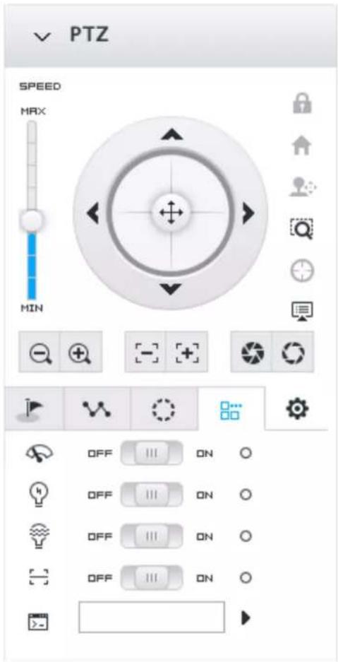
Table 7-10 PTZ Icons
| Icons Description | |
| [T66Y] | Press and hold on, and drag it up and down. The higher the value is, the faster the PTZ speed is. |
 | Control PTZ movement in the following ways.Press and hold on to control PTZ top/bottom/left/right/upper-left/upper-right/lower-left/lower-right direction.Click the arrows to control PTZ direction. |
| Click to enable 3D positioning function. | |
| [D20Y] | Click to enable auto focus, and then the camera image becomes focused automatically. |
 | Click to enter the PTZ menu mode. For details, see "7.1.3.1 PTZ Menu Settings". |
 | Zoom. Click to adjust lens zoom rate of the remote device. |
 | Focus. Click to adjust lens focus of the remote device. |
| [7OT8] | Iris. Click it to adjust iris size of the remote device. |
 | Click to use windshield wiper, light, IR and linear scan, auxiliary commands.: Drag the on/off slider to the left or right to enable or disable windshield wiper.: Drag the on/off slider to the left or right to enable or disable the light.: Drag the on/off slider to the left or right to enable or disable the IR.: Drag the on/off slider to the left or right to enable or disable linear scan.: Set the No. of auxiliary functions. Click to enable the corresponding auxiliary function. |
[T269]  | Click to enter PTZ calling page.Go to the remote device to set corresponding PTZ function before you call it.Click to enter the preset page.Click to enter the cruise page. For details, see "7.1.3.2.2 Setting a Cruise".Click to enter the pattern page. For details, see "7.1.3.2.2 Setting a Cruise". |
5.1.3.1 PTZ Menu Settings
Device displays PTZ main menu on the view window. The PTZ main menu enables you to perform camera settings, PTZ settings, system management, and more. You can use the direction and confirm buttons to set the remote device.
Step 1 Log in to PCAPP.
Step 2 Enable view and then select a remote device on the view.
Step 3 On PTZ panel, click 📋 to open the OSD menu.
Figure 7-22 PTZ menu page
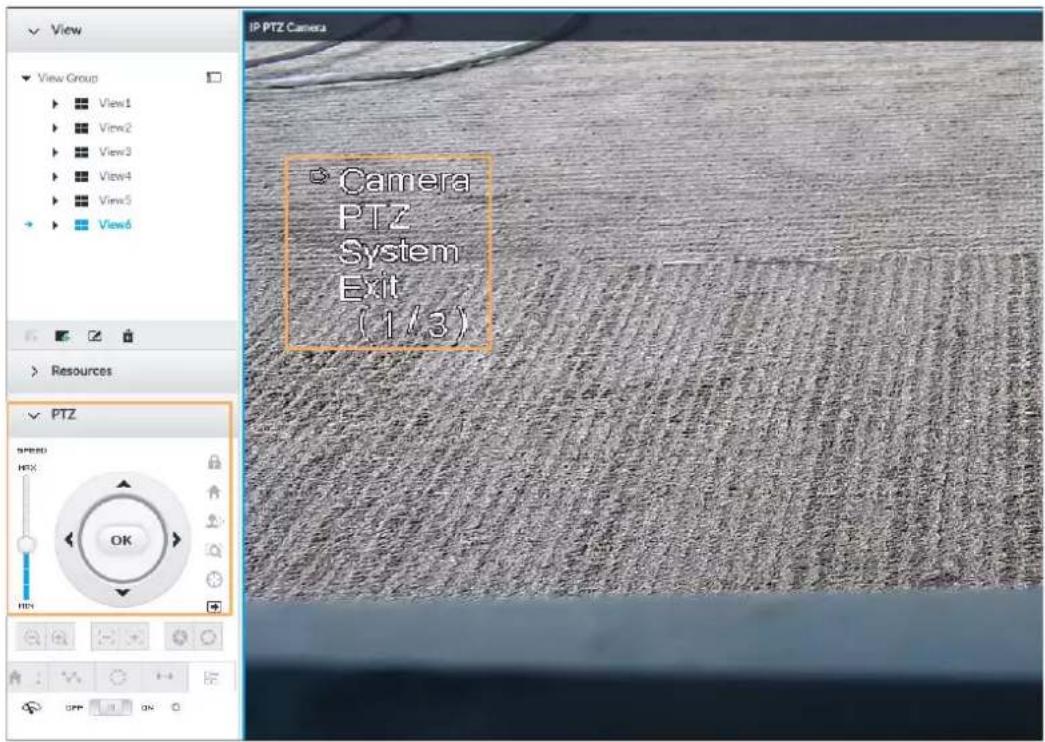
Table 7-11 PTZ menu description
| Parameters Description | |
| Camera | Set remote device image parameters involving picture, exposure, backlight, WB, day and night, focus and zoom, defog, and default. |
| PTZ | Set remote device PTZ functions such as preset, cruise, scan, pattern, rotation, and PTZ restart. |
| System | Set remote device PTZ simulator, restore default, manage remote device peripheral device, view remote device software version, PTZ version and more. |
| Exit Exit PTZ menu. |
Step 4 Set PTZ menu parameters.
- Click ▲ and ▼ to select options.
- Click > or < to set parameters.
- Click OK to confirm.
Step 5 Click ☐ to exit PTZ menu mode.
5.1.3.2 Configuring PTZ Functions
Control PTZ device to implement corresponding operations.

The PTZ functions might vary depending on the Device models.
5.1.3.2.1 Setting a Preset
A preset is the saved information of a specific position, angle, and focal length of the PTZ camera. You can set a preset so that you can quickly adjust the PTZ to the desired position in the future.
Procedure
Step 1 Log in to PCAPP.
Step 2 Select a PTZ camera from the views.
Step 3 On the PTZ panel, click .
Figure 7-23 Call a preset
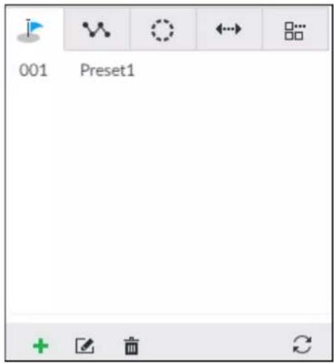
Step 4 Click the direction icons to rotate the camera to a specific position.
Step 5 Click +, enter the name of the new preset, and then click √ to save the preset.
Figure 7-24 Add a preset
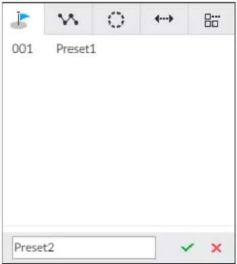
Step 6 To call the preset, hover over the preset name, and then click ▶.
Related Operations
- Edit a preset:
To edit preset name, double-click the name. The camera rotates to the preset after the double-click.
To modify the preset position, select the preset, and then click ☑, rotate the camera to the desired position, and then click √
◇ To quit, click . ✗
• To delete a preset, select it and then click 📄.
• To refresh presets list, click ↻.
5.1.3.2.2 Setting a Cruise
A cruise is a sequential set of presets. After you call a cruise, the PTZ camera automatically rotates to the presets one by one at the pre-defined interval.
Procedure
Step 1 Log in to PCAPP.
Step 2 Select a PTZ camera from the views.
Step 3 On the PTZ panel, click .
Step 4 Click +, enter the name of the new cruise, and then click √ to save.
Step 5 Click Add, select a cruise, and then click √.
Repeat this step to add multiple presets into the cruise.
Figure 7-25 Add a cruise
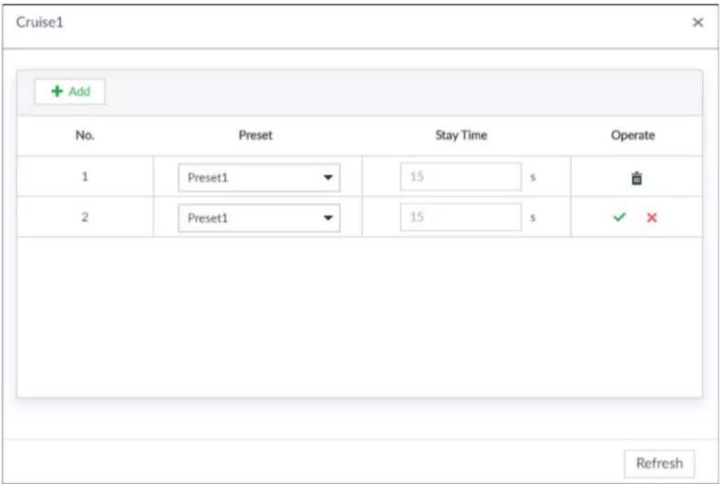
Step 6 To call the cruise, hover over the cruise name, and then click ▶. To stop the cruise, click ■.
Related Operations
- Edit a cruise:
To edit cruise name, double-click the name. To quit, click ✗.
To modify the cruise, select the cruise, and then click ☐, modify the settings, and then click √.
• To delete a cruise, select it and then click
• To refresh cruises list, click
5.1.3.2.3 Setting a Pattern
A pattern is a recorded series of PTZ operations such as pan, tilt, zoom and focusing. You call a pattern to let the camera repeat the corresponding operations.
Procedure
Step 1 Log in to PCAPP.
Step 2 Select a PTZ camera from the views.
Step 3 On the PTZ panel, click.
Step 4 To start recording a pattern, double-click on a pattern name, click Start Record, perform a series of PTZ actions as desired, and then click Stop Record.

The maximum number of patterns depends on the camera capability. If not limited on the camera, you can config up to 5 patterns by default.
Figure 7-26 Call a pattern
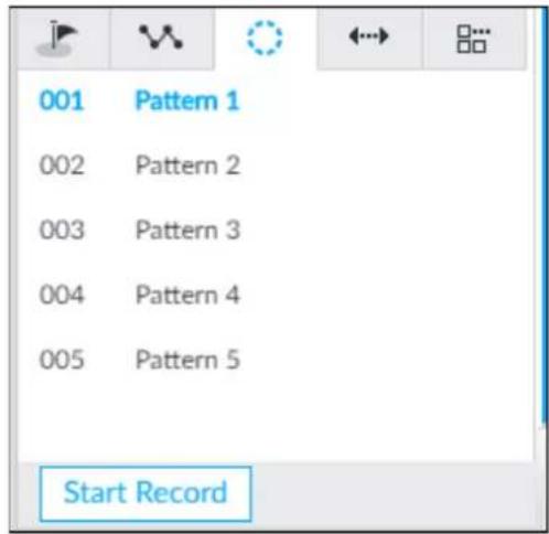
Step 5 To call the pattern, hover over the pattern name, and then click ▶. To stop, click ■.
Related\_Operations
- Edit a pattern:
To modify the pattern, select the pattern, and then click . Click Start Record and record a new pattern, and then click Stop Record.
◇ To quit, click the pattern name.
• To delete a pattern, select it and then click
• To refresh patterns list, click
5.1.3.2.4 Setting Linear Scanning
In the linear scanning mode, the camera scans repeatedly to the pre-defined left and then right limit.
Step 1 Log in to PCAPP.
Step 2 Select a PTZ camera from the views.
Step 3 On the PTZ panel, click
Step 4 Select a linear scanning, and then double-click it or click ⚙. Rotate the PTZ to the left until you think it can be the left limit, and then click ◀ to save; rotate the PTZ to the right limit, and then click ▶I.

The maximum number of linear scannings depends on the camera capability. If not limited on the camera, you can config up to 5 scannings by default.
Figure 7-27 Set a linear scanning
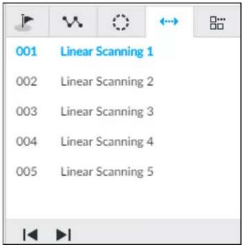
Step 5 To call the linear scanning, hover over the name, and then click ▶. To stop, click ■.
5.1.3.2.5 Enabling Auxiliary Functions
Enable PTZ windshield wiper, light and IR.
Step 1 Log in to PCAPP.
Step 2 Select a PTZ camera from the views.
Step 3 On the PTZ panel, click .
Figure 7-28 Auxiliary functions
Step 4 Drag the slider to ON or OFF to enable or disable the function.
● : Windshield wiper. It is available on select models.
● Light. It is available on select models.
• : IR. It is available on select models.
5.2 Recorded Files
Search or play back the record file or image on the Device. At the same time, you can export record file or image to designated storage path.
5.2.1 Playing Back Recorded Video
Search and playback record file according to remote device, record type, and record time.
Step 1 Click + and then select SEARCH.
Figure 5-20 Search
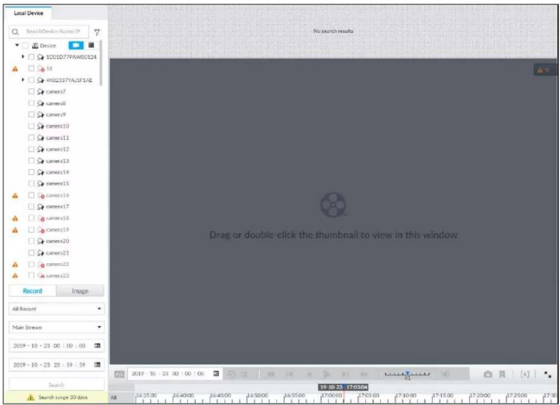
Step 2 Select a remote device, and then click Record tab.

Click to display only channels. Click to display channels and devices.
Step 3 Select a record type from among All Record, Video Detect, and IO Alarm and Thermal.
• All record: Search for all records.
- Video detect: Search for the records of video detection. For setting of video detection record, see "6.4.3.1 Video Detect".
- IO alarm: Search for local alarm linkage records. For setting of local alarm linkage record, see "6.4.3.3 IPC External Alarm".
- Thermal: Search for videos of thermal alarms. For setting of thermal alarm linkage, see "6.4.3.4 Thermal Alarm".
Step 4 Select a stream type from main stream and sub stream.
Step 5 Set search time.
• Method 1: Click the date or time on the time column, change time or date value.
- Method 2: Click the date or time on the time column, use the mouse middle button to adjust time or date value.
• Method 3: Click 📋, set date or time on the schedule, click OK.
In the schedule page, if there is a dot under one date (such as ^24 ), the date has records.
Figure 5-21 Schedule page
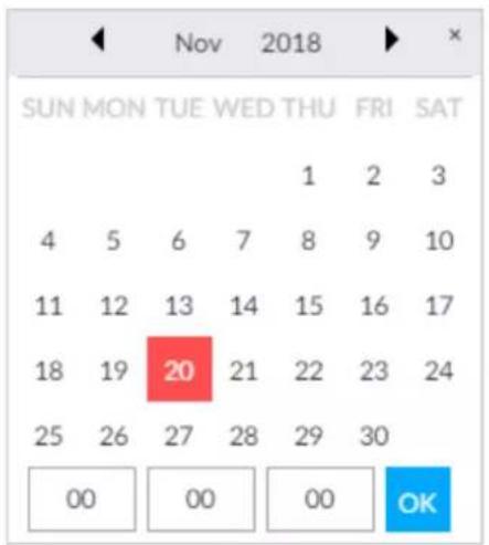
Step 6 Click Search.
The record thumbnail is at the top of the remote device, and the time bar displays the record period (green color means there is a record).

- The selected remote device is on the left panel. Click a remote device, and the record file thumbnail is on the right panel.
- Click or to move thumbnail list or hide/display the thumbnail.
- Move the mouse pointer to the thumbnail, you can view remote device name, record start time, and end time of the corresponding record.
- Move the mouse pointer to the thumbnail list. The interface displays ↗. Click the icon to hide the thumbnail list. If the thumbnail list is hidden, click ↘ to display the thumbnail list.
Figure 5-22 Search result
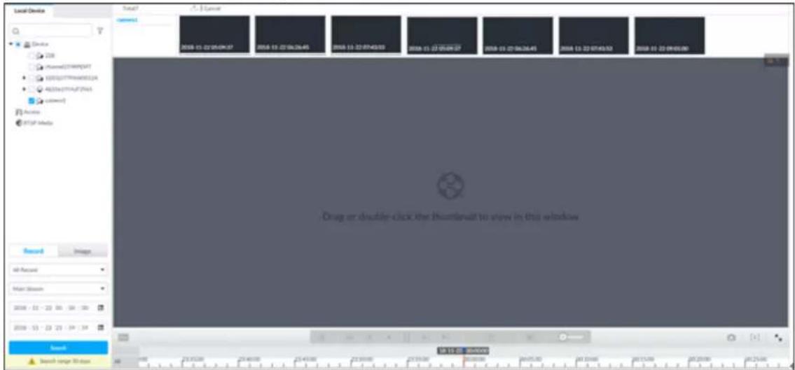
Step 7 Drag the thumbnail to the playback window or double-click the thumbnail.
Device begins playing the record.

- The playback window amount depends on the thumbnail amount you can drag or select. System supports maximum 16 windows. System automatically adjusts each window size according to the original scale of playback file.
- The thumbnail with means system is playing record file of current thumbnail.
Figure 5-23 Search
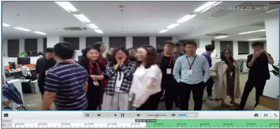
| Signal Words Description | |
 | Click to synchronize playback mode. You can use the playback control icon to control several windows, such as fast forward/backward at the same time.Click [AAOX] to cancel synchronization operation. |
 | Set a time period. Click [TDSY] start playing the videos in the set time period. |
 | Play back several record files at the same time. Click the icon to switch to time synchronization mode. All other windows play the video file of the same time of current window.Click  to cancel time synchronization.Click [XHBZ] system enables synchronization operation function. If you want to cancel synchronization, click . to cancel time synchronization.Click [XHBZ] system enables synchronization operation function. If you want to cancel synchronization, click . |
| [14YC] | Click to play back video file at slow speed.The slow speed includes × 1/2, × 1/4, × 1/8 , and × 1/16 . Click the icon once, the playback speed degrades one level. |
 | Click to switch to frame by frame backward playback.It is only valid in pause mode. |
 | Click to play backward. Now the icon becomes . Click to stop backward play. |
| [235K] | Click to start playback. Now the icon becomes . Click to pause playback video. |
 | Click to switch to frame by frame playback.It is only valid in pause mode. |
 | Click to play back at fast speed.The fast speed includes × 1, × 2, × 4, × 8 , and × 16 . Click the icon once, the playback speed upgrades one level. |
 | Displays playback speed. Drag ▼ to the left or right to playback at fast forward or fast backward. |
 | Click to capture an image. |
 | Click this icon to tag the current video. |
 | Click to obtain one part of record, and save it in designated storage path. See "5.2.2 Clipping Recorded Video" for detailed information. |
| [D3X0] | Click ▼ to mute. The icon becomes × . Click × to unmute. |
| [637K] | Click to play back at full screen. |
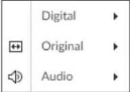 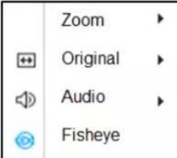 | Time bar. Displays record type and record file period.There are two record file bars on the time bar. The top bar is to display record time of selected window. The bottom bar is to display record time of all selected remote devices.The time bar adopts color to categorize record type. Green=Regular record. Red=Alarm record. Blank=No record.Time scale is to display record file date and time.System automatically adjusts time scale according to the record playback process.On the time bar, you can:◇ Click the time bar and rotate the mouse wheel button to adjust the time accuracy.Press the time bar and then drag to the left or right to move the time bar to view the hidden record time.Drag time scale to adjust start time of record playback.Click or drag the time scale to position where there is a record, system starts playing from the selected time.Click or drag the time scale to position where there is no record, system stops playing record.Shortcut menu: Right-click mouse on the playback window, you can view the shortcut menu.Zoom: It is to zoom in a specified zone and view the details. See "5.1.1.3.3 Digital Zoom" for detailed information.Original scale: Set view window scale.ON: Sys tem automatically adjusts video window scale according to the video resolution.OFF: System automatically adjusts video window scale according to the remote device amount and the free space on the playback panel.Audio: Set audio output.Fisheye: Set the installation method and display mode of fisheye camera. For details, see "5.1.1.3.4 Fisheye Dewarp". |
 | Move mouse pointer to the playback window, system pops up task column. Click the icon to close the playback window. |
5.2.2 Clipping Recorded Video
Clip one part of the recorded video, and save it in designated storage path.

Connect USB device to the system if you are on the local menu to operate.
Step 1 Click + and then select SEARCH.
Step 2 Play video file. See "5.2.1 Playing Back Recorded Video".
Step 3 Click . [↓]
Video clipping frame appears on the time bar.
Figure 5-24 Video clipping frame

Step 4 Click the record edit column (the blue column on Figure 5-24) and drag to the left or right, to select start time and end time of clipping.
Step 5 Click Save Immediately.
Figure 5-25 Save
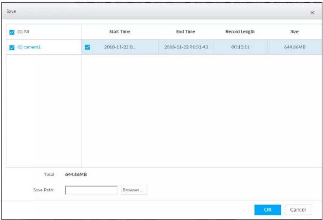
Step 6 Click Browser to select saving path.
Step 7 Click OK.
Save the clipping to designated storage path.
5.2.3 Playing Back Snapshots
Search for and play back image according to remote device, image type, and snapshot time.
Step 1 Click + and then select SEARCH.
Step 2 Select a remote device, and then click Image.

System supports maximum 1 remote device.
Figure 5-26 Image playback (1)
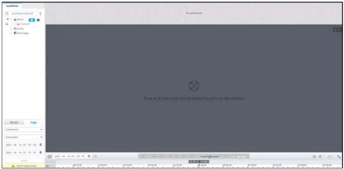
Step 3 Select image type, including video detect, IO alarm and thermal, and then select detection type as needed.
Step 4 Set search time.
• Method 1: Click the date or time on the time column, change time or date value.
- Method 2: Click the date or time on the time column, use the mouse wheel to adjust time or date value.
Method 3: Click , set date or time on the schedule, click OK.
In the schedule page, if there is a dot under one date (such as ^24 ), the date has records.
Figure 5-27 Schedule page
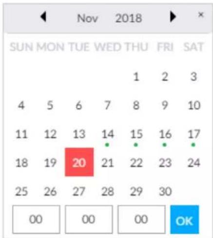
Step 5 Click Search.
Figure 5-28 Image thumbnail
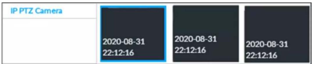

- The selected remote device is on the left panel. Click a remote device, and the image thumbnail is on the right panel.
- Click or to move thumbnail list, and display the hidden thumbnail.
- Move the mouse pointer to the thumbnail, you can view remote device name, and snapshot time of the corresponding thumbnail.
- Move the mouse pointer to the thumbnail list. The interface displays 🔊. Click the icon to hide the thumbnail list. If the thumbnail list is hidden, click 🔼 to display the thumbnail list.
Step 6 Drag the thumbnail to the playback window or double-click the thumbnail.
Device begins playing the image.
Figure 5-29 Image playback (2)
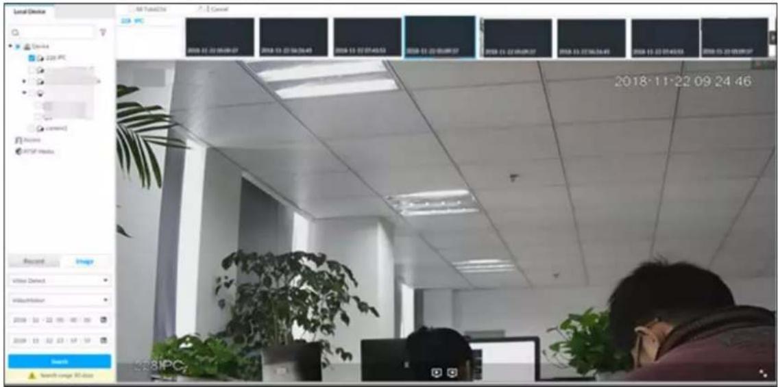

Move the mouse pointer to the playback window, you can see the following icons.
Table 5-10 Icons
| Icon Description | |
 | Click to switch to the previous image or the next image. |
 | Switch to the previous or next image or image group.When playing one image, click the icon to go to the previous image or the next image.When playing several images at the same time, click the icon to go to the previous group or the next group. |
 | Click to display at full screen. Click again to cancel full screen. |
5.2.4 Exporting File
Export record file or image to the designated storage path.

- The default record file mode is .dav and the image file mode is .jpg.
- Connect USB device to the system if you are on the local menu to operate.
Step 1
Click

and then select SEARCH.
Figure 5-30 Search (1)
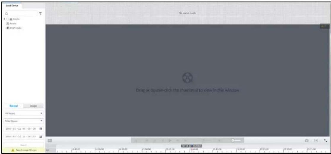
Step 2 Search record file or image.
1) Click Record or Image tab.
2) Select a remote device and then set search criteria.
3) Click Query.
Step 3 Select the record file or image you want to export.
- Move the mouse pointer to the thumbnail and then click □ to select the thumbnail.
means checked.
- Click Cancel to cancel all record files or images.
Step 4 Select file storage path.
1) Click ↗ and then select Export record or Export image.

The following steps are to export video file. See the actual page for detailed information.
2) Click OK.
Figure 5-31 Save
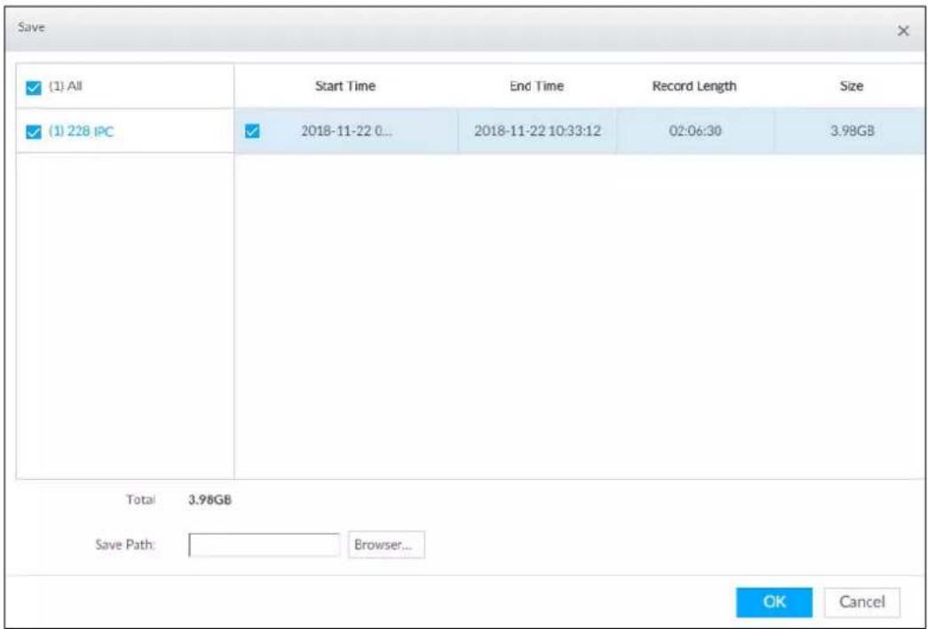
3) Click Browser to select saving path.

For local menu operation, after you set storage path, the Save page displays Format button. Click Format button to clear all data on the USB storage device. The formatting operation will clear all data. Be cautious.
4) Click OK.
Device goes back to Save page.
Step 5 Click OK.
The system starts to export files. The file downloading page is displayed.
Figure 5-32 Download
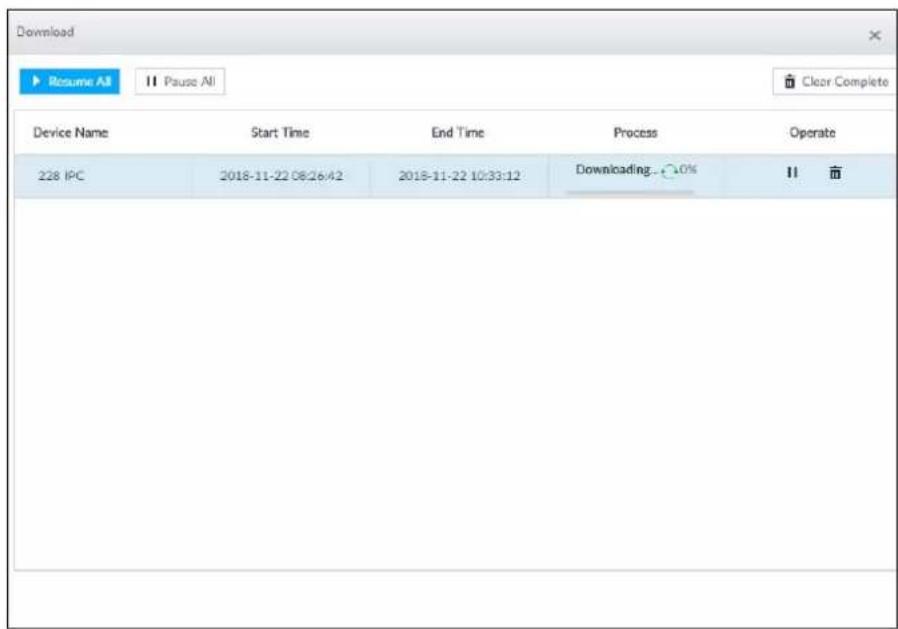
- Click Pause all to pause all download tasks. Click Start all to resume download tasks.
-
Click Clear completed columns to delete all downloaded tasks.
-
Click " of the corresponding task to pause download task. Click ▶ to resume download.
- Click of the corresponding task to delete download task.
5.2.5 Video Tag
Tag specific video segments or pictures for the ease of search. For details about viewing tagged files, see "7.1.1 Video Tag Management".
Step 1 Click + , and then select SEARCH.
Step 2 Search for pictures or videos.
1) Click the Record or Image tab.
2) Select a camera, and then set search conditions.
3) Click Search.
Step 3 Click at the lower-right corner of the playback window.
Figure 5-33 Tag
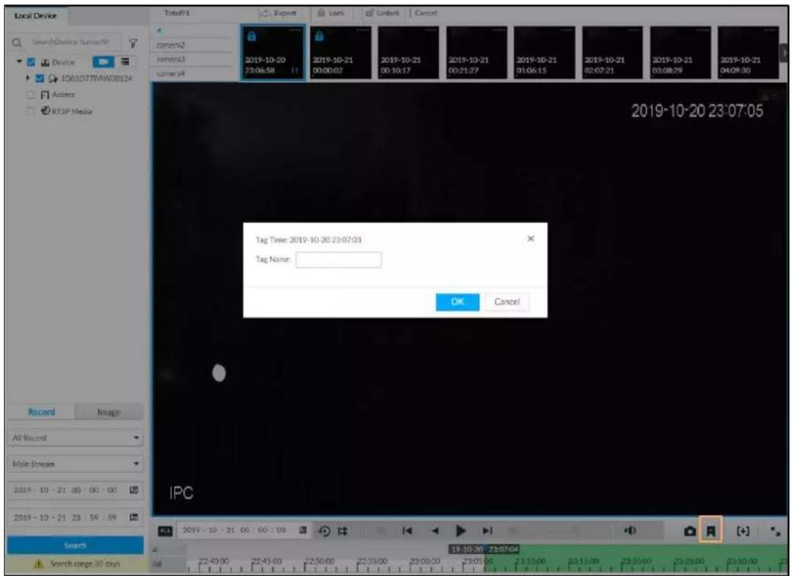
Step 4 Enter tag name, and then click OK.
5.2.6 Locking Files
Lock specific videos or pictures so they cannot be viewed. A locked file can only be viewed after being unlocked.
Step 1 Click + , and then select SEARCH.
Step 2 Search for pictures or videos.
1) Click the Record or Image tab.
2) Select a camera, and then set search conditions.
3) Click Search.
Step 3 Select the video files to be locked.
- Point to the thumbnail, and then click □ to select the video.
• You can click Cancel to cancel the selected videos.
Step 4 Click Lock.
Step 5 (Optional) Click Unlock to unlock the locked videos.
You can also unlock videos in FILE > FILE LOCKED. See "7.1.2 FILE LOCKED".
5.3 Alarm List
Click 9 to display alarm list. View alarm device name, alarm time and alarm type.
Figure 5-34 Alarm list
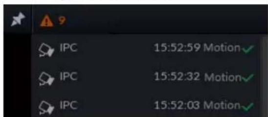
- Number 9 is the number of alarm event to be processed. The value changes according to alarm amount. It displays maximum 200 unprocessed alarm events.
- Click to lock alarm list. The alarm list is open and cannot hide. Click the icon again to cancel lock function. Move the mouse pointer to other position, and the alarm list displays for a period of time and then automatically hides.
- Click √ to confirm alarm event. The confirmed event will be removed from the alarm list.
- Click the alarm event on the alarm list. The device displays the 20 seconds video before and after the alarm event occurred.
Click 📊 to pause play. Now the icon becomes ▶. Click ▷ again to continue to play.
◇ Click OK and close, confirm the alarm event and then exit the page.
Figure 5-35 Alarm video
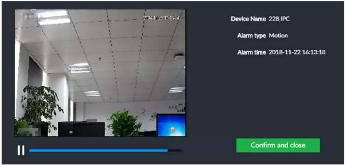
5.4 System Information
View system information including system error, system alarm and system notification.
Click to display background task list.
Figure 5-36 System information
- Click All, Error, Warning, or Notification tab to view the corresponding system information list.
- Click 📄 to clear the corresponding system information.
- Click Clear to clear system information under current tab. For example, click All tab and then click Clear button to clear all system information. Click Error tab and then click Clear button to clear all system error information.
5.5 Background Task
View background task running status.
Click 📄, device displays background task list. Click All, Running, or Waiting to view the corresponding background task list.
Figure 5-37 Background task
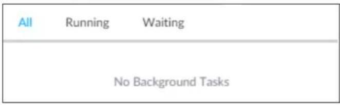
5.6 Buzzer
View buzzer alarm messages.
Click The alarm messages are displayed.
Figure 5-38 Buzzer
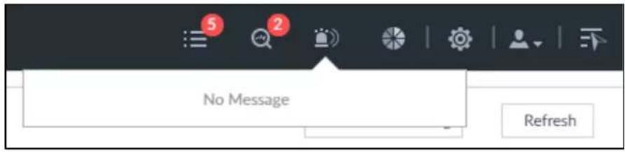
6 System Configuration
This chapter introduces system configuration functions such as managing remote device, setting network, setting alarm event, setting HDD storage, managing user information, setting device security strategy, and setting system parameters.
6.1 Configuration Page
Click 🤿. The following page is displayed.
Figure 6-1 Configuration page
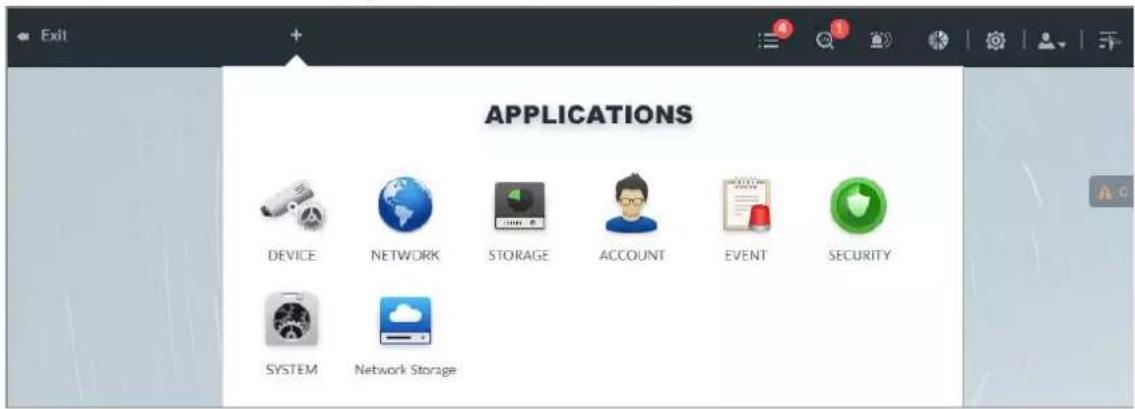
On this page, you can:
- Click the corresponding app icon to go to the corresponding page. The task column displays current running app name. Move the mouse pointer to the app name and then click ✗ to close the app.
- Click Exit to exit the page.
6.2 Device Management
Click 🎨 or click + on the configuration page, and then select DEVICE. The DEVICE page is displayed. You can set EVS or remote devices.
- Select the root node in the resource tree to set EVS name and storage plan.
- Select a remote device in the Device list. Set its property, connection, video, OSD, and storage plan.

Click + or click Add to add remote device to the system. See "3.4.2 Adding Remote Device" for detailed information.
Figure 6-2 Device management
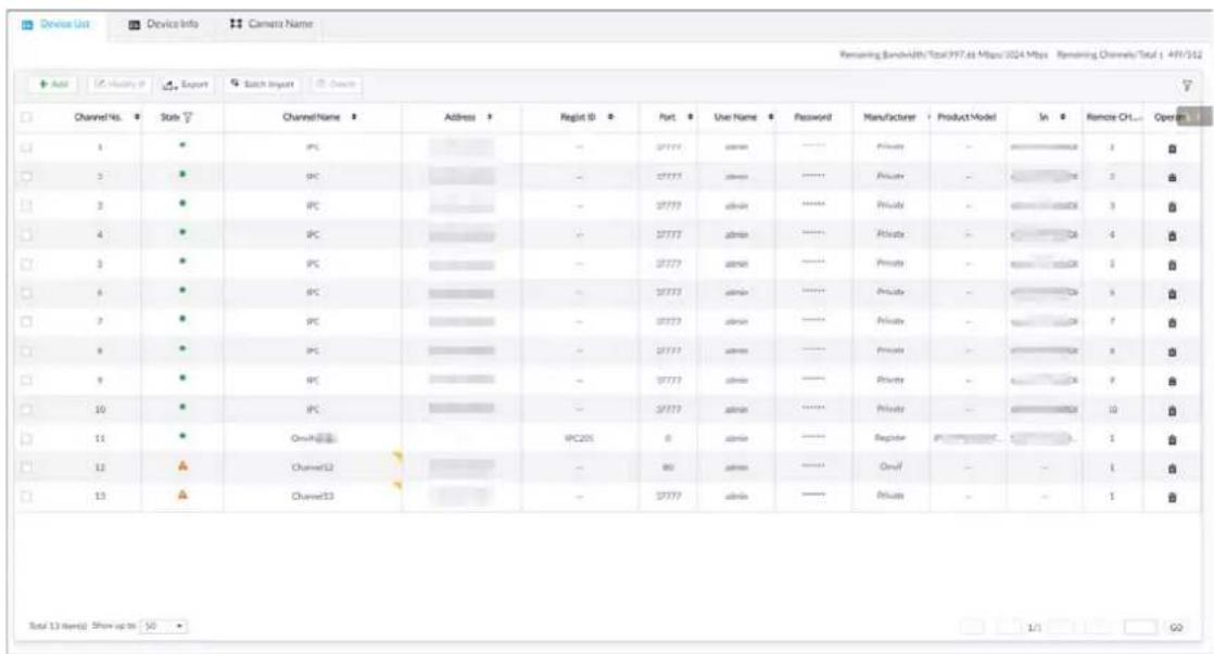
6.2.1 Viewing Device Information
View information of the Device.
Step 1 Click , and then select DEVICE.
Step 2 Select the root node in the resource tree, and then click the Device Info tab.
Step 3 Set parameters.
Figure 6-3 Device info
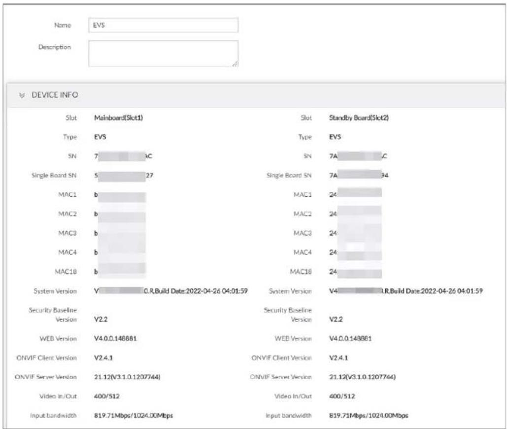
bar
| Device | Name | Description | | :--- | :--- | :--- | | DEVICE INFO | | | | Slot | Mainboard(Slot1) | Slot Standby Board(Slot2) | | Type | EVS | Type EVS | | SN | 7 AC | SN 7A ,C | | Single Board SN | 5 27 | Single Board SN 7A 94 | | MAC1 | b | MAC1 24 | | MAC2 | b | MAC2 24 | | MAC3 | b | MAC3 24 | | MAC4 | b | MAC4 24 | | MAC10 | b | MAC10 24 | | System Version | V 0.R.Build Date:2022-04-26 04:01:59 | System Version V4 0.R.Build Date:2022-04-26 04:01:59 | | Security Baseline Version | V2.2 | Security Baseline Version V2.2 | | WEB Version | V4.0.0.148881 | WEB Version V4.0.0.148881 | | ONVIF Client Version | V2.4.1 | ONVIF Client Version V2.4.1 | | ONVIF Server Version | 21.12(V3.1.0.1207744) | ONVIF Server Version 21.12(V3.1.0.1207744) | | Video In/Out | 400/512 | Video In/Out 400/512 | | Input bandwidth | 819.71Mbps/1024.00Mbps | Input bandwidth 819.71Mbps/1024.00Mbps |Table 6-1 Device info parameters
| Parameters Description | |
| Name | Set device name. |
| Description | Enter device description. |
| Device info | Displays device info, including device SN, mainboard SN, MAC, video in/out, input bandwidth, system version, security baseline version, and web version. |
Step 4 Click Save.
6.2.2 Remote Devices
Add remote devices, change IP addresses and configurations, and export remote device information.

See "3.4.2 Adding Remote Device" for detailed information.
6.2.2.1 Viewing Remote Devices
View connected remote devices. For details about adding devices, see "3.4 Configuring Remote Device".
Step 1 Click 📋, or click + on the configuration page, and then select DEVICE.
Step 2 Select the root node in the resource tree, and then click the Device List tab.
Figure 6-4 Device list
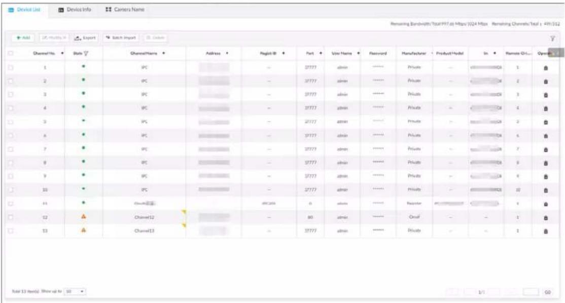
Step 3 View details of connected devices, including IP address and serial number.
• In the State column, ● indicates that the Device is offline.
• In the State column, ● indicates that the Device is online.
- In the State column, ⚠ indicates that the Device is exception. Point to ⚠, and then you are prompted about the details of the exception, such as being uninitialized, device mismatch, and wrong password.
Step 4 (Optional) Click 📋 to set searching conditions.
Step 5 (Optional) You can select the uninitialized devices to initialize them. For details, see "3.4.1 Initializing Remote Device".
6.2.2.2 Changing IP Address
Modify IP address of the remote device connected or not connected to the Device.
6.2.2.2.1 Modifying IP of Unconnected Devices

- You can only modify the IP address of initialized devices. For remote device initialization, see "3.4.1 Initializing Remote Device" for detailed information.
- You can only modify the IP address of remote devices connected with private protocol.
Step 1 Click 🎨, or click + on the configuration page, and then select DEVICE.
Step 2 Click + or click Add, and then select Smart Add.
Step 3 Click Start Search.
Figure 6-5 Remote device
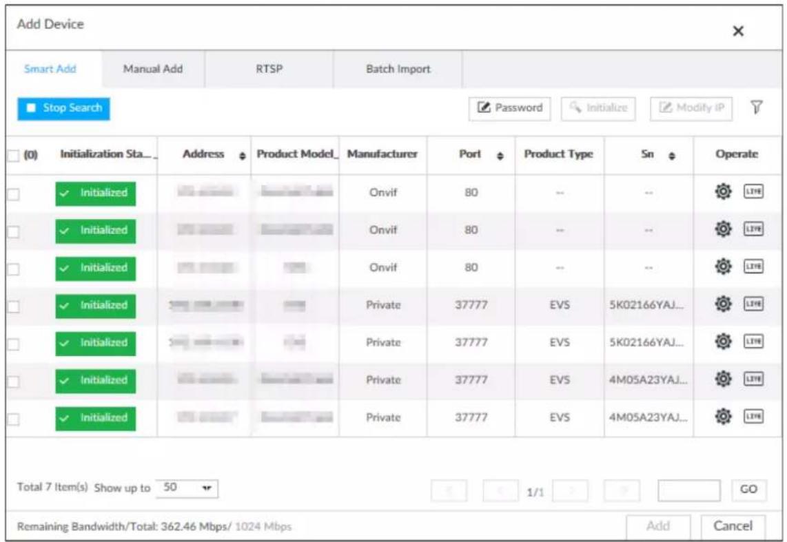
Step 4 Select a remote device and then click Modify IP.
Figure 6-6 Modify IP
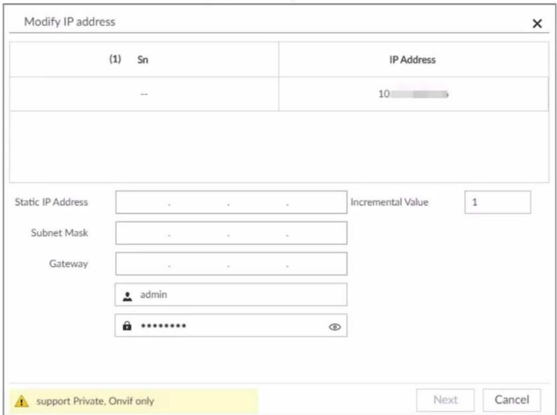
Step 5 Enter the static IP address, subnet mask, gateway, and incremental value.

- Enter incremental value only when multiple remote devices are modified. If you want to change IP addresses of several devices at the same time, system allocates IP address one by one according to your setting at the fourth bit of the IP address.
- If there is IP conflict when changing static IP address, device pops up IP conflict dialogue box. To change IP addresses in batches, system automatically skips the conflicted IP and begins the allocation according to the incremental value.
Step 6 Enter the username and password of remote device.

When you are changing several device IP addresses, make sure that the username and password of these remote devices are the same.
Step 7 Click Next.
The modification result is displayed.
Step 8 Click OK to complete the modification.
6.2.2.2.2 Modifying IP of Connected Devices

- You can only modify the IP address of initialized devices. For remote device initialization, see "3.4.1 Initializing Remote Device" for detailed information.
- You can only modify the IP address of remote devices connected through private protocol.
- To modify the IP address of connected devices one by one, see "6.2.2.3.2 Configuring Connection Information".
Step 1
Click

or click

on the configuration page, and then select DEVICE.
Figure 6-7 Device management
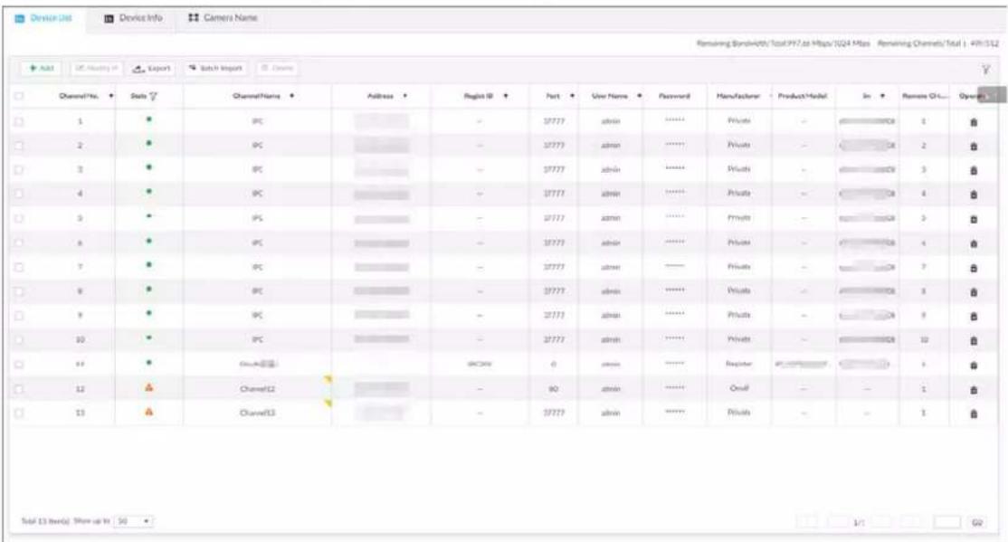
Step 2 Select a remote device and then click Modify IP.
Figure 6-8 Modify IP
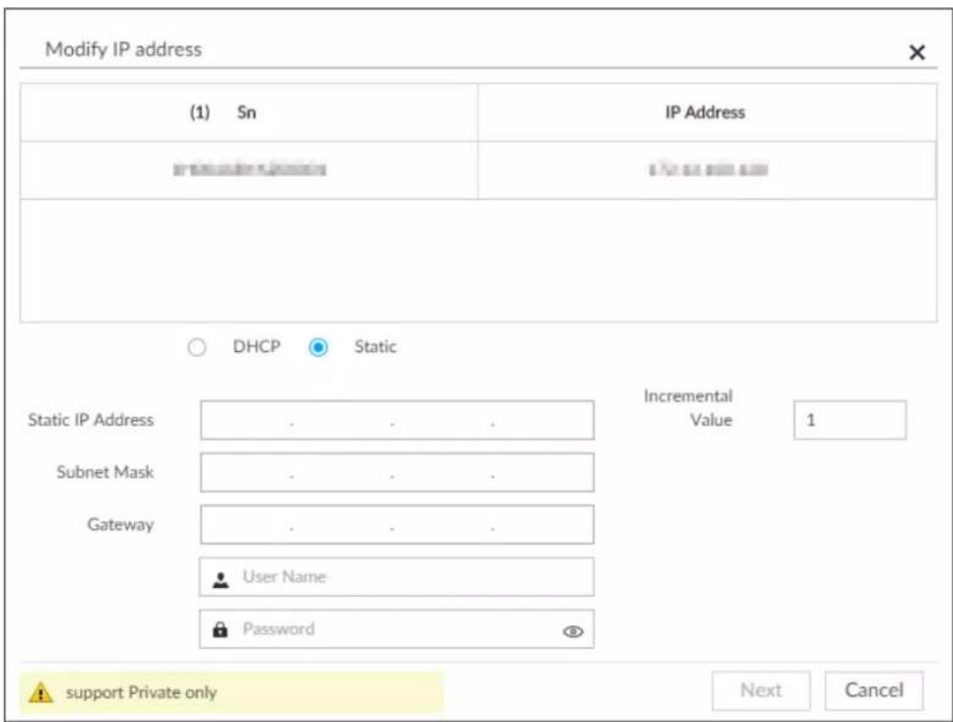
Step 3 Enter the IP address, subnet mask, gateway, and incremental value.

- Enter incremental value only when multiple remote devices are modified. If you want to change IP addresses of several devices at the same time, system allocates IP address one by one according to your setting at the fourth bit of the IP address.
- If there is IP conflict when changing static IP address, device pops up IP conflict dialogue box. To change IP addresses in batches, system automatically skips the conflicted IP and begins the allocation according to the incremental value.
Step 4 Enter the username and password of remote device.

When you are changing several device IP addresses, make sure that the username and password of these remote devices are the same.
Step 5 Click Next.
The result of IP modification is displayed.
Step 6 Click OK.
6.2.2.3 Configuring Remote Devices
Set remote device property, connection information, and video parameters.

Different remote devices have different pages. See the actual page for detailed information.
6.2.2.3.1 Viewing Device Property
Set remote device name, and view device information.
Step 1 Click 🎨, or click + on the configuration page, and then select DEVICE.
Step 2 Select a remote device on the left panel and then click Property tab.
Step 3 Set parameters.
Table 6-2 Property parameters description
| Parameters Description | |
| Name | Set remote device name. Enable Sync to remote device and save the settings to synchronize new name to the remote device. |
| Description | Input remote device description. |
| DEVICE INFO | Displays remote device information. It includes remote device type, SN, MAC address, video in/out, audio in/out, alarm in/out, and system version. |
Step 4 Click Save.
6.2.2.3.2 Configuring Connection Information
Set connection information of remote device, such as IP address and port number.
Step 1 Click 🎨, or click + on the configuration page, and then select DEVICE.
Step 2 Select a remote device on the left panel and then click the Connection tab. Step 3 Change IP address.
1) Click of the corresponding address.
2) Enter IP address, subnet mask and gateway.
3) Click Test to test whether the IP address is valid.
Figure 6-9 Modify IP
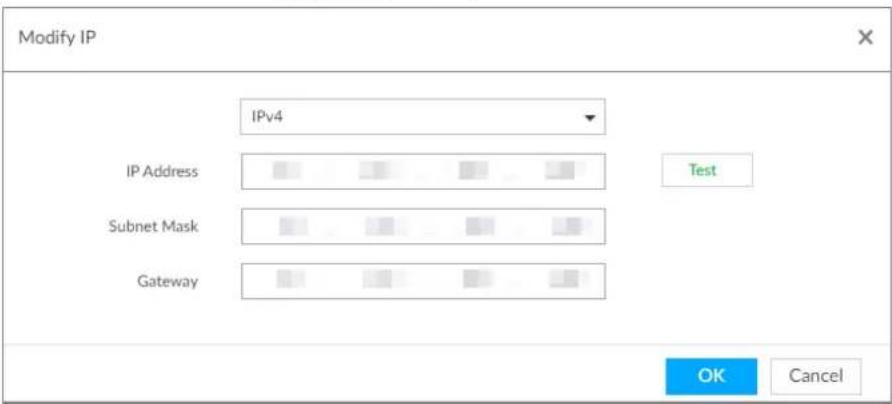
4) Click OK to save setting.
Step 4 Change port number.
1) Click of the corresponding port.
The Modify Port page is displayed. See Figure 6-10.
Figure 6-10 Port
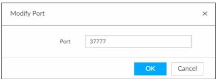
2) Change port number.
3) Click OK to save setting.
Step 5 Set other parameters.
Table 6-3 Connection parameters description
| Parameters Description | |
| Manufacturer | Displays the connection protocol of the remote device. |
| User Name | Enter username and password of remote device.The password should consist of 8 to 32 non-blank characters and contain at least two types of characters among uppercase, lowercase, number, and special character (excluding '";: &). Enter a strong password according to the password strength indication. |
| Password | |
| Link type | Displays link type of the system and remote device. It is self-adaptive. |
Step 6 Click Save.
Step 7 (Optional) Click , and then you can go to the web interface of the remote device.

On the local interface of the Device, you cannot click e to go to the web interface of the remote device.
6.2.2.3.3 Configuring Video Parameters
Set different video parameters according to different bit stream types based on the bandwidth.
Step 1 Click 🎨, or click + on the configuration page, and then select DEVICE.
Step 2 Select a remote device on the left panel and then click Video tab.
Figure 6-11 Video
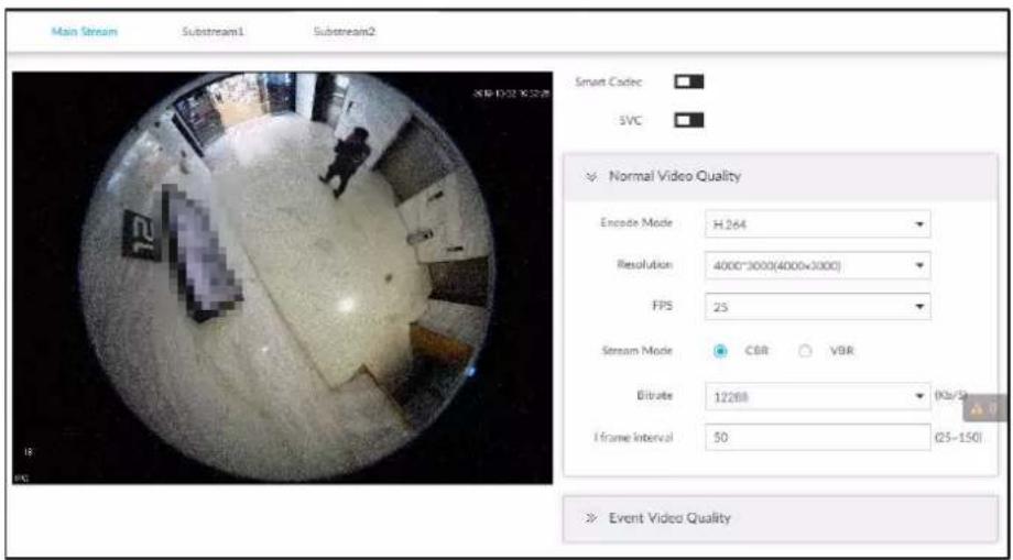
Step 3 Set main stream, sub stream 1, or sub stream 2.
Step 4 Set general video quality parameters.
Table 6-4 Video parameters description
| Parameters | Description |
| Smart Codec | Enable this function to enhance performance of video compression and thus reduce storage space requirement. This function is only available for main stream. This function is only available for main stream. |
| SVC | Select the checkbox to enable SVC function. Select 1 or 2 from the drop-down list on the right. The default setup is 1, there is no scaled encoding.SVC refers to the scaled video coding. It can split the video stream to basic stream and enhanced scale. |
| Encode mode | Set video encode mode.H.264: It is a highly compressed video encoding or encoding standard. At the same video quality, it has increased the compression rate by 2X compared with the MPEG-2.H.265: It is a new video encode standard coming after H.264. It has improved the complicated relationship among bit stream, encode quality, latch and algorithm on the previous standard. It can get the best encoding. |
| Resolution | Set video resolution. The higher the resolution is, the better the video quality is.Different series products support different resolutions. See the actual page for detailed information. |
| FPS | Set the frame amount displayed at each second. The higher the frame rate is, the more vivid and fluent the video is. |
| Stream mode | Set video bit stream control mode.CBR: The bit stream changes slightly. The bit stream is near the value you set here.VBR: The bit stream might change according to the environment. |
| Quality | Set video quality. It includes low, middle, high. |
| It is null when the stream mode is CBR. | |
| Bitrate | Set video bitrate.● Main stream: In the Bit Rate list, select a value or enter a customized value to change the image quality. The larger the value is, the better the image will become.● Sub stream: In CBR mode, the bit stream changes around the value you set. In VBR mode, it changes according to the bit stream value, but its max value is near the specified value. |
| I frame interval | Set the P frame amount between two I frames. Usually we recommend it is the 2X of the frame rate. |
This function is only available for main stream.
Step 5 Enable Event Video Quality and set FPS and stream mode.

Event video quality is for main stream only.
Step 6 Click Save.
6.2.2.3.4 Configuring OSD
Configure overlay time information, and channel information on the video.
Step 1 Click 🎨, or click + on the configuration page, and then select DEVICE.
Step 2 Select a remote device on the left panel and then click OSD tab.
Figure 6-12 OSD
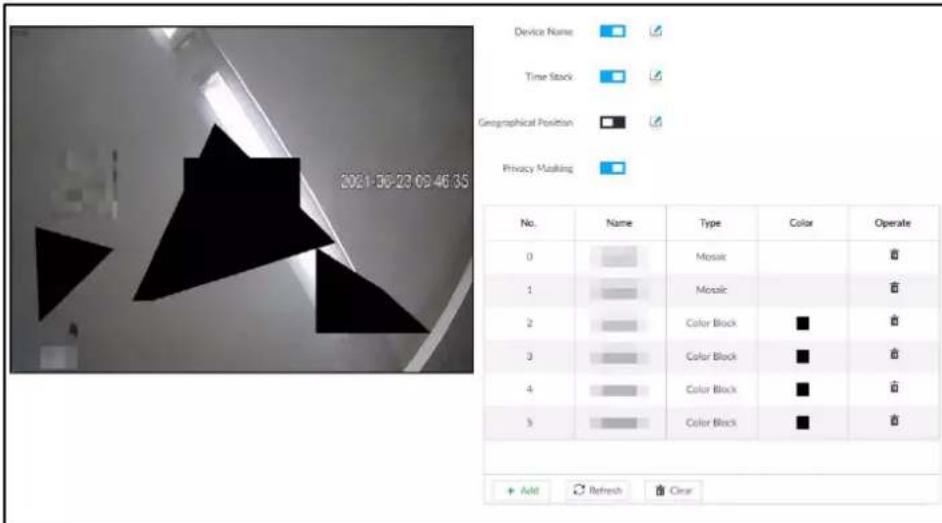
Step 3 Enable OSD information according to actual requirements.
- Set device name
-
Click □ to enable OSD of device name.
-
Click .
-
Enter device name.
Figure 6-13 Device name

- Drag the text box to the proper position.
- Click ☐ to save the OSD information.
- Set time information
- Click to enable OSD of time.
- Click .
Figure 6-14 Time

- Drag the text box to the proper position.
- Click ☐ to save the OSD information.
- Set geographical position
- Click □ to enable OSD of geographical position.
- Click .
- Enter the geographical position information.

Click to adjust the alignment of text boxes.
◇ Click ☑ or ☑ to create a text box.
◇ Click to delete a text box.
Figure 6-15 Geographical position
- Drag the text box to the proper position.
- Click ☐ to save the OSD information.
- Set privacy masking

This function is available only when the camera supports privacy masking.
-
Click □ to enable privacy masking.
-
Click Add, select the masking type and color, and then draw mosaic or color blocks in the image as needed.
-
Drag blocks to the proper position.
-
Click to save the OSD information.
Step 4 Click Save.
6.2.2.3.5 Configuring Audio Parameters
Step 1 Click ⚙, or click + on the configuration page, and then select DEVICE.
Step 2 Select a remote device on the left panel and then click Audio tab.
Figure 6-16 Audio
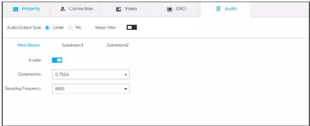
Step 3 Select an audio output type.
• Lineln: The Device acquires audio signals through external audio device.
- Mic: The Device acquires audio signals through internal mic.
Step 4 Click to enable Noise Filter.
Step 5 Click the Main Stream, Substream1 or Substream2 tab, and then configure the parameters.
Table 6-5 Audio parameters
| Parameter Description | |
| Compression | The audio encoding mode set here applies to both audio streams and voice talks. We recommend leaving it as default. |
| Sampling Frequency | The number of samples of a sound that are taken per second. The higher the value, the more accurate the digital representation of the sound can be. |
Step 6 Click Save.
6.2.2.4 Exporting Remote Devices in Batches
Export the added remote device. When the Device restores factory default settings or information of remote device is lost, export information of remote device to recover quickly.

See "3.4.2 Adding Remote Device" for detailed information.
Step 1 Click 🎨, or click + on the configuration page, and then select DEVICE.
Step 2 Click at the lower-left corner.

Click Download Template to download template file of the remote device, and add remote device through the template.
Figure 6-17 Export
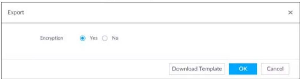
Step 3 Select encryption or not.
- If you select Yes, the system exports encrypted .backup file.
- If you select No, the system exports .csv file, which can be opened with Excel. The exported .csv file contains IP address, registration ID, port number, channel number, channel name, manufacturer, username (excluding password), link type, remote channel number, product model and SN of the remote device.

When unencrypted file is exported, keep the file properly to avoid data leakage.
Step 4 Click OK.
Step 5 Click Save.
File path might be different depending on page operations. See actual pages.
- On PCAPP, click ≡, select Download to view file saving path. For details, see "9.3 Viewing Downloads".
- Select file saving path during local operation.

Connect USB device to the system if you are on the local menu to operate.
- During web operations, files are saved under default downloading path of the browser.
6.2.2.5 Importing Remote Devices in Batches
Import devices in batches by using the template.
On the Device List page, click Batch Import to go to the Add Device page. On the Add Device page, click the Import CSV File tab. For further operation instruction about how to use the CSV file to import devices in batches, see "3.4.2.4 Batch Add".
Figure 6-18 Import in batches
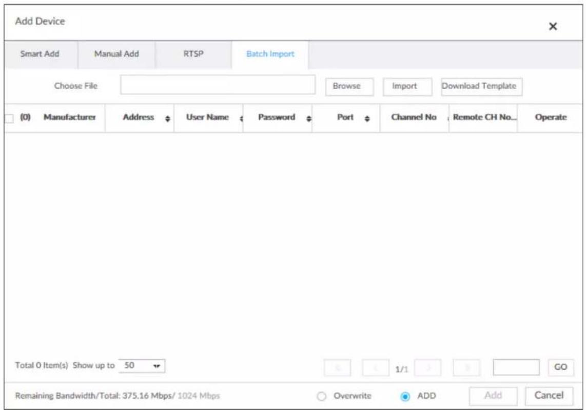
6.2.2.6 Connecting Remote Devices
On the Device page, view connection status of remote device in the Device list.
When the remote device name and icon is black, SDT5A403 for example, it means the remote device is online. When they are gray, C2 8249 for example, it means the remote device is offline.
- Right-click the offline device, and then select Connect to connect the Device.
- Right-click the online device, and then select Disconnect to disconnect the Device.
- Right-click the online device, and then select Open WEB to go to the web interface of the Device.
Figure 6-19 Device list
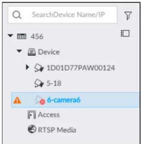
6.2.2.7 Deleting Remote Devices
On the Device page, delete the registered remote device.
- Delete one by one:
◇ Select a remote device and then click 📄 to delete.
On the Device List page, right-click a remote device and then click Delete.
On the Device List page, select a remote device, and then click
On the Device List page, select a remote device, and then click Delete.
- Batch delete:
Click ☐, device list displays checkbox for you to select multiple remote devices. Click to delete the selected devices.
On the Device List page, select multiple remote devices, and then click Delete.
6.2.2.8 Configuring Camera Name
You can view and change the name of the connected cameras.
Step 1 Log in to PCAPP.
Step 2 Click 🎨, or click + on the configuration page, and then select DEVICE.
Step 3 Select the root node in the resource tree and then click the Camera Name tab.
Figure 6-20 Camera name
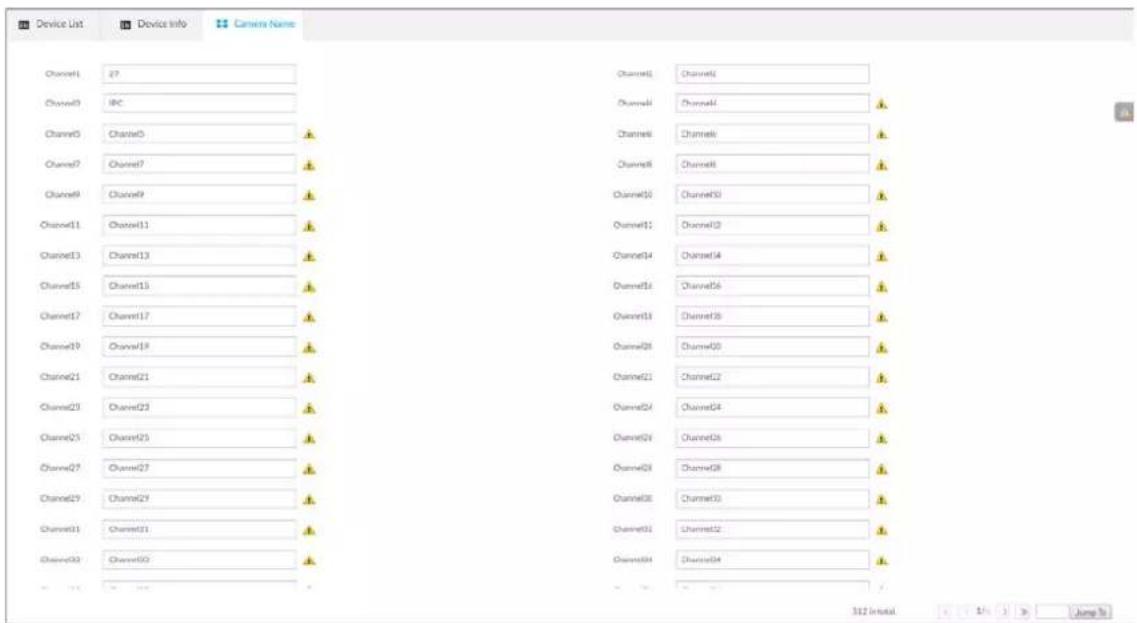
Step 4 Select a channel, enter a new name, and then click Save.
6.3 Network Management
Click 🎨 or click + on the configuration page, select NETWORK. The NETWORK page is displayed. You can set basic network parameters and application.
Figure 6-21 Network management
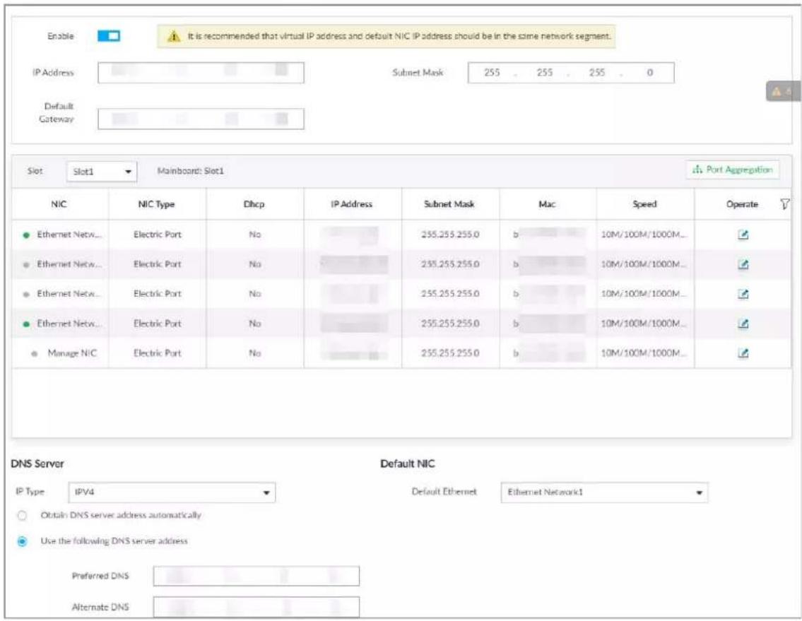
6.3.1 Basic Network
Set basic network parameters of the Device, such as IP address, port aggregation and port number, to connect with other devices in the network.
6.3.1.1 Configuring IP Address
Set device IP address, DNS server information and other information according to network planning.

Make sure that at least one Ethernet port has connected to the network before you set IP address.
Step 1 Click 🎨 or click + on the configuration page, and then select NETWORK > Basic Network > TCP/IP.

Click ↻ to view the NIC parameter information.
Figure 6-22 TCP/IP
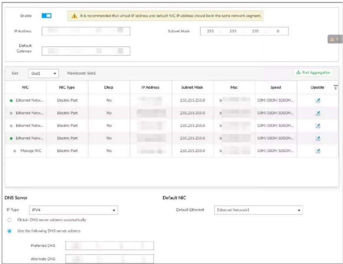
Step 2 Click ☐ to enable the virtual IP address, and then set the virtual IP address, subnet mask and default gateway.
The main board and standby board have their respective physical IP. After setting the virtual IP, despite the switch between the main and standby boards, you can always log in to the web interface with the virtual IP.

The default virtual IP address is 192.168.0.108. We recommend you set the virtual IP address and the IP address of the default NIC on the same network segment.
Step 3 Select a slot from Slot1 and Slot2.
Step 4 Click of the corresponding NIC.
Figure 6-23 Edit Ethernet network
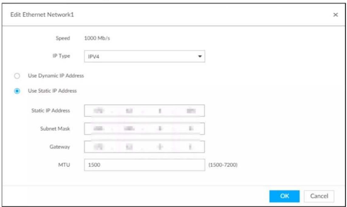
Step 5 Set parameters.
Table 6-6 TCP/IP parameters description
| Parameters Description | |
| Speed | Current NIC max network transmission speed. |
| IP Type | Select IPv4 or IPv6. |
| Use Dynamic IP Address | When there is a DHCP server on the network, check the box to use dynamic IP address, system can allocate an dynamic IP address to the Device. There is no need to set IP address manually. |
| Use Static IP Address | Check the box to use static IP address. Set static IP address, subnet mask and gateway. Set a static IP address for the Device. |
| MTU | Set NIC MTU value. The default setup is 1500 Byte.We recommend you check the MTU value of the gateway first and then set the Device MTU value equal to or smaller than the gateway value. Reduce the packets slightly and enhance network transmission efficiency.[BXHW]Changing MTU value might result in NIC reboot, network offline and affect current running operation. Please be careful! |
Step 6 Click OK.
Go back to TCP/IP page.
Step 7 Set DNS server information.
You can select to get DNS server manually or input DNS server information.

This step is compulsive if you want to use domain service.
- Check the box to auto get DNS server address, device can automatically get the DNS server IP address on the network.
- Check the box to use the following DNS server addresses, and then enter primary DNS and alternate DNS IP address.
Step 8 Set default NIC.
Select default NIC from the drop-down list.

Make sure that the default NIC is online.
Step 9 Click Save.
6.3.1.2 Port Aggregation
Bind multiple NIC to create one logic NIC and use one IP address for peripheral device. The bonded NIC can work as the specified aggregation mode to work. It enhances network bandwidth and network reliability.
System supports configuring load balance, fault tolerance, and link aggregation. See Table 6-7.
Table 6-7 Aggregation mode description
| Aggregation mode | Description |
| Load balance | Device has bonded several NICs at the same time and use one IP address to communicate with the external device. The bonded NICs are working together to bear the network load.The load balance mode adds the network throughput data amount and enhances network flexibility and availability. In this mode, the network is offline once all NICs break down. |
| Fault-tolerance | In this mode, device has bonded several NICs and set one NIC as the main card and the rest NICs are the alternative NICs. Usually, only the main NIC card is working. System can automatically enable other alternate cards to work when the main card breaks down.Fault-tolerance is a network mode to enhance NIC reliability. In this mode, the network is offline once all NICs break down. |
| Link aggregation | Device has bonded several NICs and all NICs are working together to share the network load. System allocates data to each NIC according to your allocated strategy. Once the system detects that one NIC breaks down, it stops sending data with this NIC, and then system transmits the data among the rest NICs. System calculates transmission data again after malfunctioning NIC resumes work.In this mode, the network is offline once all bonded NICs are malfunctioning.Make sure that the switch supports link aggregation and you have set the link aggregation mode. |
6.3.1.2.2 Binding NIC
System supports load balance, fault-tolerance, and link aggregation. Select bind mode according to your actual requirements.
Step 1 Click 🎨 or click + on the configuration page, and then select NETWORK > Basic Network > TCP/IP.
Step 2 Bind NICs.
1) Click Port Aggregation.
Figure 6-24 Port aggregation
| Port Aggregation | ||||||
| NIC | NIC Type | Dhcp | IP Address | Subnet Mask | Mac | Speed |
| Ethernet Network1 | Electric Port | No | 10M/100M/1000MSelf-... | |||
| Ethernet Network2 | Electric Port | No | 10M/100M/1000MSelf-... | |||
| Ethernet Network3 | Electric Port | No | 10M/100M/1000MSelf-... | |||
| Ethernet Network4 | Electric Port | No | 10M/100M/1000MSelf-... | |||
| Manage NIC | Electric Port | No | 10M/100M/1000MSelf-... | |||
2) Select the NICs you want to bind.
3) Select an aggregation mode.
4) Click Port Aggregation.

The setting page varies depending on the aggregation mode you have selected. Figure 6-25 is the load balance setting page.
Figure 6-25 Edit load balance
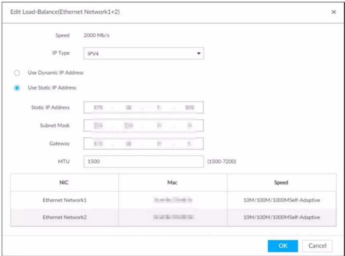
5) Set parameters.
Table 6-8 TCP/IP parameters description
| Parameters Description | |
| Speed | Maximum network transmission speed of current NIC. |
| IP Type | Select IPv4 or IPv6. |
| Use Dynamic IP Address | When there is a DHCP server on the network, check the box to use dynamic IP address. System can allocate a dynamic IP address to the Device. There is no need to set IP address manually. |
| Use Static IP Address | Check the box to use static IP address. Set static IP address, subnet mask and gateway. Set a static IP address for the Device. |
| MTU | Set NIC MTU value. The value is 1500 bytes by default.We recommend you check the MTU value of the gateway first and then set the Device MTU value equal to or smaller than the gateway value. Reduce the packets slightly and enhance network transmission efficiency. Changing MTU value might result in NIC reboot, network offline and affect current running operation. Please be careful! Changing MTU value might result in NIC reboot, network offline and affect current running operation. Please be careful! |
6) Click OK.
Step 3 Click Save.
Step 4 Click OK to save the configuration.
The binding card information becomes activated after reboot operation.
6.3.1.2.3 Cancelling Binding NIC
Cancel port aggregation and allow the bonded NICs to work as independent card.
Step 1 Click 🎨 or click + on the configuration page, and then select NETWORK > Basic Network > TCP/IP.
Step 2 Select a bound NIC.
Figure 6-26 Confirm
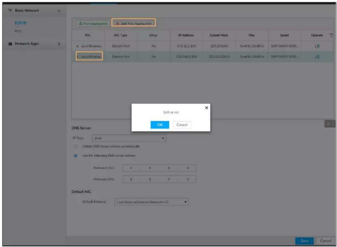
Step 3 Click OK.
System splits the bonded NIC.

After splitting NIC binding, the first NIC reserves the IP address configured during binding, while the rest NICs restore default IP addresses.
6.3.1.3 Setting Port Number
Step 1 Click 🎨, or click + on the configuration page, and then select NETWORK > Basic Network > Port.
Figure 6-27 Port
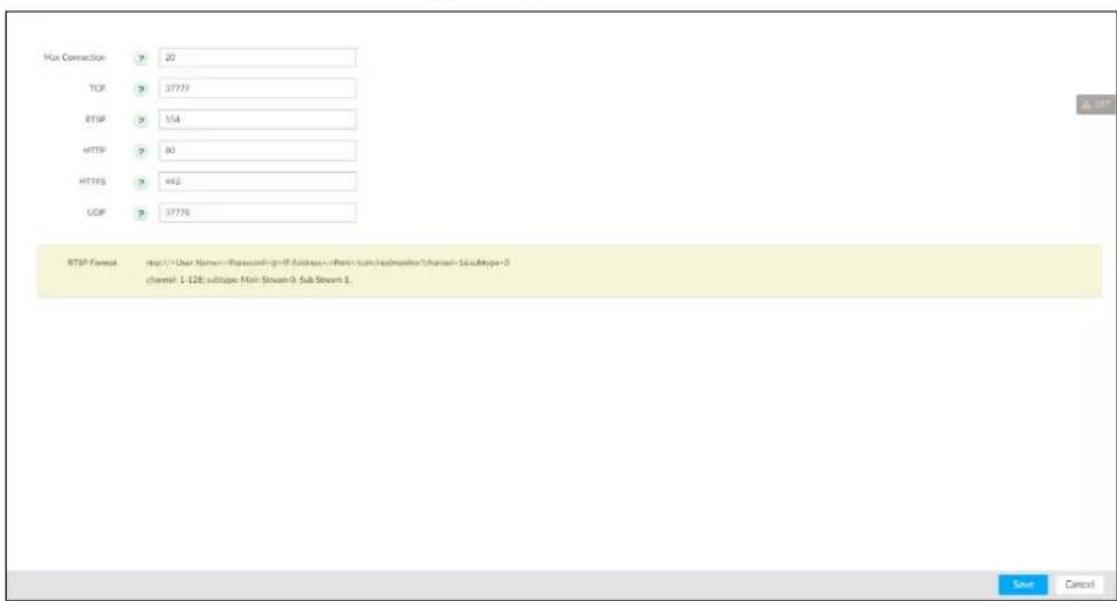
Step 2 Set parameters.

Log in again after modifying parameters except Max Connection.
Table 6-9 Connection setting parameters description
| Parameters Description | |
| Max Connection | The allowable maximum clients accessing the Device at the same time, such as web, PCAPP, and Platform. Select a value between 1 and 128. The default value setting is 20. |
| TCP Port | Set according to the actual requirements. The default value is 37777. The value ranges from 1025 to 65535. |
| RTSP Port | Set according to the actual requirements. The default value is 554. The value ranges from 1 to 65535. |
| HTTP Port | Set according to the actual requirements. The default value is 80. The value ranges from 1 to 65535.If the value you set is not 80, please add the port number after the IP address when you are using browser to login the Device. |
| HTTPS Port | Set according to the actual requirements. The default value is 443. The value ranges from 1 to 65535. |
| UDP Port | Set according to the actual requirements. The default value is 37778. The value ranges from 1025 to 65535. |
Step 3 Click Save.
System reboots corresponding service of the port.
6.3.2 Network Apps
Set device network parameters, so that system can connect to other devices.
6.3.2.1 P2P
P2P is a peer to peer technology. You can scan the QR code to download cellphone APP without DDNS service or the port mapping or installing the transmission server. After register the Device to the APP, you can view the remote video, playback record file and so on.

• Make sure that the system has connected to the network. Otherwise, the P2P function is null.
- When using the P2P function, we will collect device information such as IP address, MAC address, name and serial number. The collected information is only used for remote access.
Step 1 Click 🔍, or click + on the configuration page, and then select NETWORK > Network Apps>P2P.
The P2P page is displayed. Scan the QR code on the actual page.
Figure 6-28 P2P
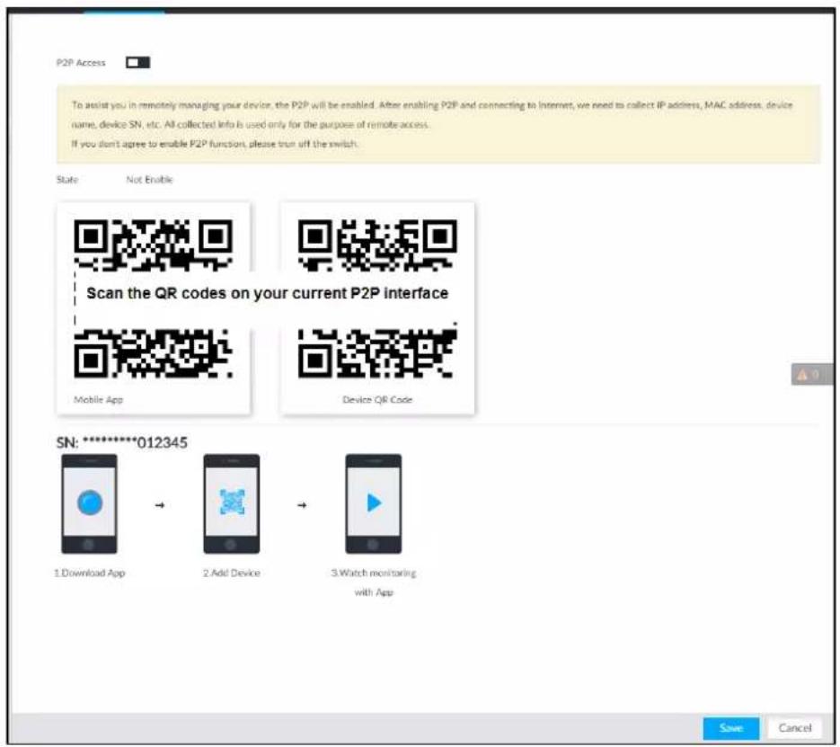
Step 2 Click to enable P2P function.
Step 3 Click Save.
After the configuration, you can register a device to the APP to view remote video, playback record file, and so on. See corresponding cellphone APP for detailed information.

After successfully connected to the P2P, the status displayed as Success.
6.3.2.2 DDNS
After setting DDNS parameters, when IP address of EVS changes frequently, the system dynamically updates the relation between domain name and IP address on DNS server. You can use domain name to remotely access EVS, without need to note down IP address.
Preparation
Confirm whether EVS supports the DDNS Type and log in the website provided by the DDNS service provider to register the information such as domain from PC located in the WAN.

After you have registered and logged in the DDNS website successfully, you can view the information of all the connected devices under this username.
Procedure
Step 1 Click 🎨, or click + on the configuration page, and then select NETWORK > Basic Network > DDNS.
Figure 6-29 DDNS
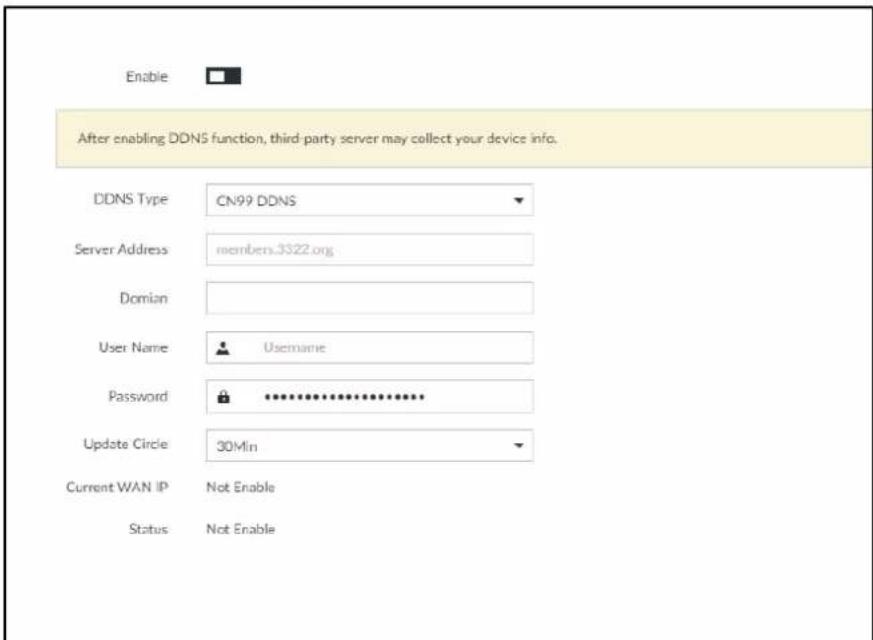
Step 2 Click to enable DDNS function.

After enabling DDNS function, the third-party server might collect your device information. Pay attention to privacy security.
Step 3 Set the corresponding parameters.
Table 6-10 DDNS setting parameters description
| Parameters Description | |
| DDNS Type | Name and address of DDNS service provider.● Dyndns DDNS: members.dyndns.org● NO-IP DDNS: dynupdate.no-ip.com● CN99 DDNS: members.3322.org |
| Server Address | |
| Domain | The domain name for registering on the website of DDNS service provider. |
| Username | Enter the username and password obtained from DDNS service provider. You need to register (including username and password) on the website of DDNS service provider. |
| Password | |
| Update Circle | Enter the amount of time that you want to update the DDNS. |
| Current WAN IP | Displays the WAN IP address of EVS. |
| Status | Displays DDNS registration result or update status. |
Step 4 Click Save.
After successful configuration, enter domain name in address bar of the browser or PCAPP, and press Enter key to access the EVS.
6.3.2.3 Email
Configure email information, and enable alarm linkage email. When NVR has alarm events, the system automatically sends emails to the user.

Device data will be sent to specific servers after the email function is enabled. Be cautious.
Step 1 Click 🎨, or click + on the configuration page, and then select NETWORK > Network Apps > Email.
Figure 6-30 Configuring email
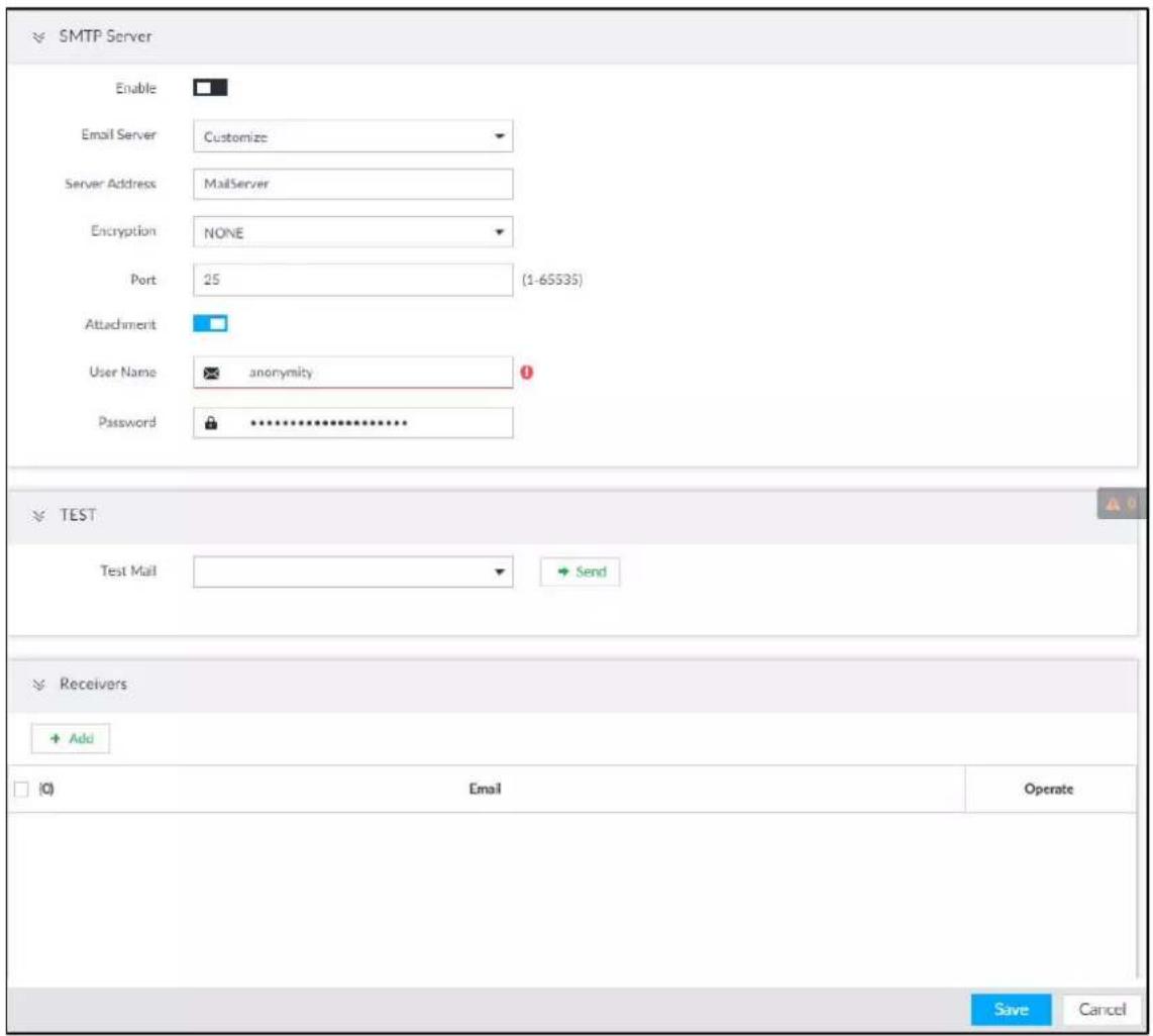
Step 2 Click □ to enable the email function.
Step 3 Set parameters.
Table 6-11 EMAIL parameter description
| Parameters Description | |
| Email Server | Select email server type, including Customize, Gmail, Hotmail, and Yahoo. |
| Server Address | Enter email server address. |
| Encryption | Select encryption type of email server, including NONE, SSL, and TLS.You are recommended to select TLS. The other encryption methods might not be safe. |
| Port | Enter the port number of email server. |
| User name and password | Enter the configured username and password of email server. |
Step 4 Add the information of email receiver.
1) Click Add.
2) Enter a receiver email address.
Figure 6-31 Email address

3) Click Add or + to add other receiver email address.
- Click ☐ to delete the added receiver.
- Select a receiver. The Delete button is displayed. Click Delete button to delete the selected receiver.
Step 5 Click Save.
Step 6 (Optional) Test the email sending function.
1) In Test Mail, select or enter a receiver email address.
2) Click Send.
- When the configuration is correct, the system pops up a message of success, and the receiver will receive the test mail.
- Otherwise, the system pops up a message of failure, and the receiver will not receive the test mail.
6.3.2.4 SNMP
After setting SNMP (Simple Network Management Protocol) and successfully connecting devices through relevant software tools such as MIB Builder, and MG-SOFT MIB Browser, you can directly manage and monitor devices on software tools.

- Install SNMP device monitoring and management tools, such as MIB Builder and MG-SOFT MIB Browser.
- Obtain the MIB file corresponding to the current version from technical support.
Step 1 Click 🎨, or click + on the configuration page, and then select NETWORK >Network Apps > SNMP.
Figure 6-32 SNMP (1)
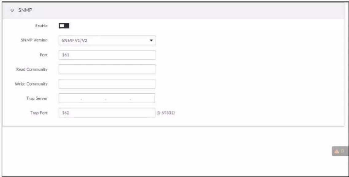
Step 2 Click to enable the function.
Step 3 Select SNMP version.
• If you have selected SNMP V1/V2, see Figure 6-32.

SNMP V1/V2 has security risks. You are recommended to use SNMP V3.
• If you have selected SNMP V3, see Figure 6-33.
Figure 6-33 SNMP (2)
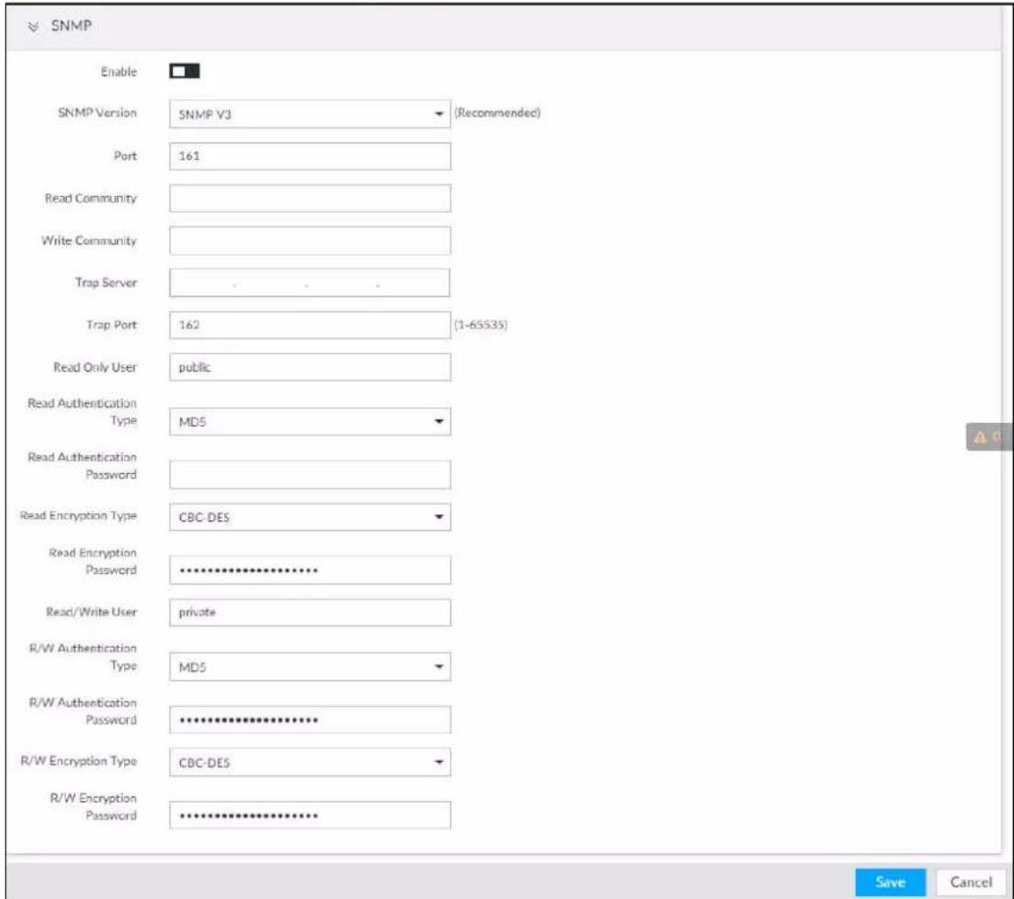
Step 4 Set parameters. For Trap server address, enter the IP address of the PC that has MG-SOFT MIB Browser. Keep the other parameters as default.
Table 6-12 SNMP parameters
| Parameters Description | |
| Port | Listening port of agent programs on the Device. |
| Read Community | Read or Write Community supported by the agent programs. |
| Write Community | The name can only contain numbers, letters, underscores, and middle lines. |
| Trap Server | The destination address of Trap information sent by the agent program. |
| Trap Port | The destination port of Trap information sent by the agent program. |
| Read Only User | Set the username the read-only user. The read-only user can only have the read-only permission. |
| The name can only contain numbers, letters, and underscores. | |
| Read Authentication Type | You can select MD5 or SHA. It is MD5 by default. |
| Read Authentication Password | The password must contain at least 8 digits. |
| Read Encryption Type | CFB-AES by default. |
| Read Encryption Password | The password must contain at least 8 digits. |
| Read/Write User | The username is private by default. If you log in using this username, you have the read-and-write permission.The name can only contain numbers, letters, and underscores. |
| R/W Authentication Type | You can select MD5 or SHA. It is MD5 by default. |
| R/W Authentication Password | The password must contain at least 8 digits. |
| R/W Encryption Type | CFB-AES by default. |
| R/W Encryption Password | The password must contain at least 8 digits. |
Step 5 Click Save.
6.3.2.5 Register
Register the Device on designated proxy server, and client software visits the Device through the proxy server.
Step 1 Click 🎨, or click + on the configuration page, and then select NETWORK > Network Apps > REGISTER.
Figure 6-34 Register
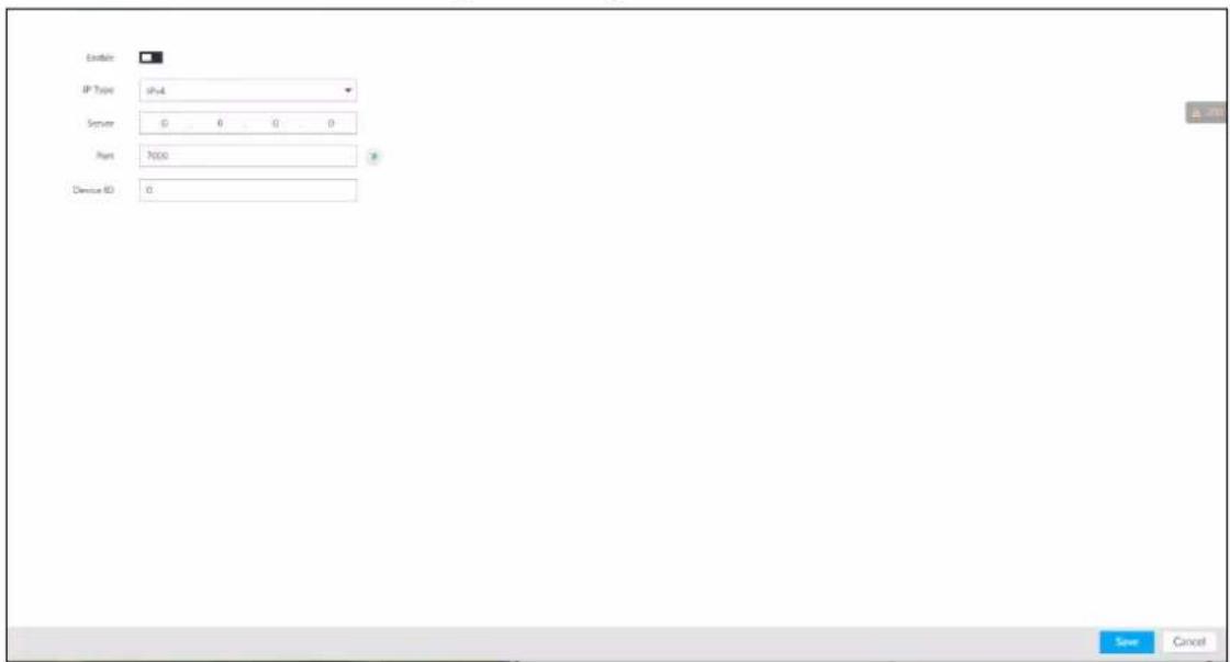
Step 2 Click to enable the function.
Step 3 Set parameters.
Table 6-13 Register
| Parameters | Description |
| IP Type | Select IP address of server for registration. |
| Server | In the Server box, enter the IP address of server for registration. |
| Port | Enter the port number of the server for registration. |
| Device ID | Enter Device ID to identify EVS uniquely. Device ID shall be consistent with server configuration. |
Step 4 Click Save.
6.3.2.6 UPnP
Through the UPnP (Universal Plug and Play) protocol, you can establish a mapping relationship between the LAN and the WAN, the WAN user can use the WAN IP address to directly access the Device in the LAN.

Device services and ports will be mapped to the public network after UPnP is enabled. Be cautious.

• Make sure that your PC has UPnP network services installed.
- Log in to the router and set the WAN port IP address of router.
- Enables the UPnP function on the router.
- Connect the Device to the router LAN (Local Area Network, LAN) port.
- Select NETWORK >Basic Network >TCP/IP, and then set the IP address to be the private-network IP of the router, or select DHCP to automatically obtain the IP address.
Step 1
Click

or click

on the configuration page, and then select NETWORK > Network
Apps > UPnP.
Figure 6-35 UPnP
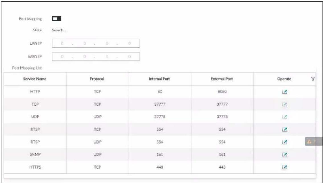
Step 2 Set parameters.
Table 6-14 UPnP parameters
| Parameters Description | |
| Port Mapping | Click to enable UPnP. |
| State The status of port mapping. | |
| LAN IP | The LAN IP address of router.The IP address is automatically obtained after the mapping succeeds. |
| WAN IP | The WAN IP address of router.The IP address is automatically obtained after the mapping succeeds. |
| Port Mapping List | The list is consistent with the UPnP port mapping list on the router.Internal Port: The EVS port to be mapped on the router.External Port: The WAN port of the internal port.When setting the external port, use the ports between 1024 and 5000, and do not use the well-known ports 1 to 255 and the system ports 256 to 1023, so as to avoid conflicts.When there are multiple devices within the LAN, properly plan the port mapping to avoid conflicts of WAN ports.When making a port mapping, make sure that the port you are mapping is not occupied or restricted.The TCP/UDP WAN and LAN ports must be consistent and cannot be modified. |
| Modification | Click , and then you can modify the external port. |
Step 3 Click Save.
Enter http://WAN IP: WAN port number in the browser to access the Device with the corresponding port number in the router network.
6.3.2.7 Multicast
When multiple users are viewing live video of the same device at the same time, it might cause failure due to limited bandwidth. To solve this problem, you can set a multicast IP address (224.0.0.0-239.255.255.255) for the Device.
Step 1 Click 🎨, or click + on the configuration page, and then select NETWORK > Network Apps > Multicast.
Figure 6-36 Multicast
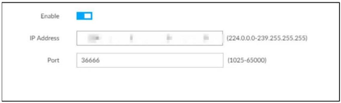
Step 2 Click to enable multicast.
Step 3 Set parameters.
Table 6-15 Parameters
| Parameters | Description |
| IP Address | Set the multicast IP address of the Device (224.0.1.0–239.255.255.255). |
| Port | Set the multicast port (1025–65000). |
Step 4 Click Save.
After configuring the multicast address and port, you can log in to the web interface or PCAPP client through the multicast protocol.
Take PCAPP for example. On the login interface of PCAPP, select Multicast as the login type. The PCAPP client will automatically obtain the multicast address and join the multicast group. After login, you can view live videos through multicast protocol.
Figure 6-37 Log in through multicast
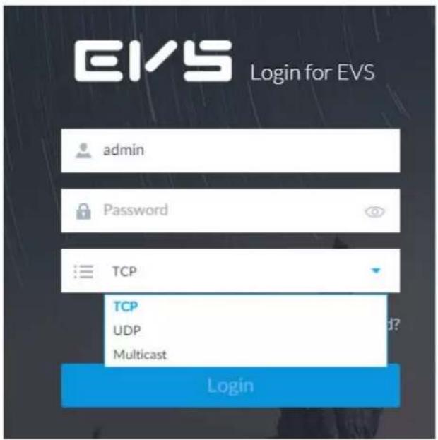
6.3.2.8 Alarm Center
You can configure the alarm center server to receive the uploaded alarm information.

Make sure that alarm center server is deployed.
Step 1 Click 🎨, or click + on the configuration page, and then select NETWORK > Network Apps > Alarm Center.
Figure 6-38 Alarm center
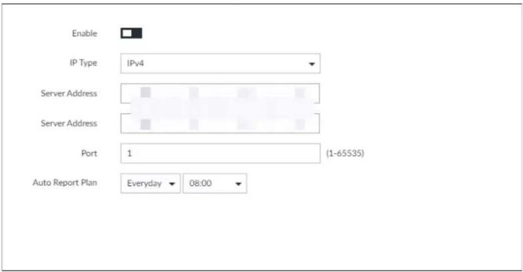
Step 2 Click □ to enable alarm center.
Step 3 Configure the parameters.
Table 6-16 Alarm center parameters
| Parameter Description | |
| IP Type | Select the IP type of the alarm center server. |
| Server Address | The IP address and communication port of the alarm center server. |
| Port | |
| Auto Report Plan | Select time cycle and specific time for uploading alarm. |
Step 4 Click Save.
6.3.2.9 Route Table
Configure the route table so that the system can automatically calculate the best path for data transmission.
Step 1 Click 🎨, or click + on the configuration page, and then select NETWORK > Network Apps > Route Table.
Step 2 Click Add.
Figure 6-39 Add route table
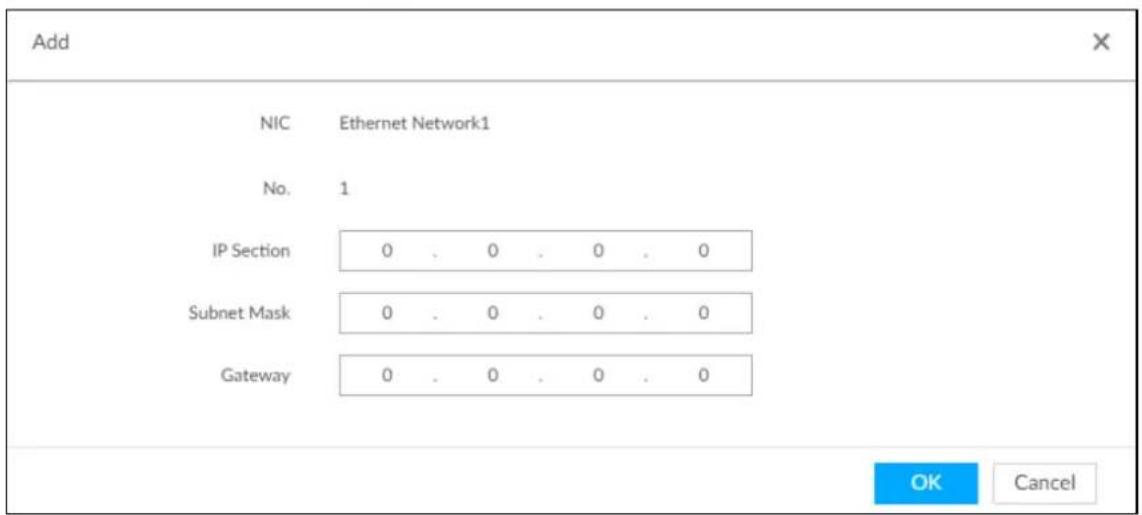
Step 3 Enter the information.
Step 4 Click OK.
6.4 Event Management
Click 🎨 or click + on the configuration page, select EVENT.
On the page, configure alarm event, including alarm event of EVS and remote device.
- Select the root node in the resource tree on the left to set alarm event of the Device. See "6.4.2 Local Device" for detailed information.
- Select remote device in the device tree on the left, to set alarm event of this remote device. See "6.4.3 Remote Device" for detailed information.

- The alarm event might be different depending on the model you purchased.
• √ means that the corresponding alarm event has been enabled.
• means that AI by Camera has been enabled.
Figure 6-40 Event management
| Overview Overview Charming | Filter | |||||||||||||
| DEVICE INFO | Fact | Video Metadata | Ins | Vehicle | Crowd Do... - Call Detect... - Smoking Do... - People Go... - | |||||||||
| Channel No. | State | Channel Name | Address/Regist ID | |||||||||||
| 1 | ● | 27 | 10:37:16:11:35 | |||||||||||
| 2 | ● | Channel2 | 10:37:16:2-51 | |||||||||||
| 3 | ● | PC | 10:37:19:189 | ● | ||||||||||
| Abnormal Event Device Offline | ||||||||||||||
6.4.1 Alarm Actions
System can trigger the corresponding actions when an alarm occurs.

The supported actions might be different depending on the model you purchased.
On the alarm configuration page, click Actions to display actions. See Table 6-17 for detailed information. Configure actions according to your actual need.
• After setting actions, click Save on the page.
• After enabling actions, click ✗ to disable the corresponding actions.
Table 6-17 Actions description
| Actions Description | Preparation | |
| Record | The system links the selected remote device to record when there is a corresponding alarm event. | Remote device, such as IPC, has been added. See "3.4.2 Adding Remote Device" for detailed information. |
| Buzzer | The system activates a buzzer alarm when there is a corresponding alarm event. | — |
| Log | The system notes down the alarm information in the log when there is a corresponding alarm event. | — |
| The system sends alarm email to all added receivers when there is corresponding an alarm event. | Email configuration has been completed. See "6.3.2.3 Email" for detailed information. | |
| Snapshot | The system takes snapshots of the linked channel when there is corresponding alarm event. | — |
| Preset | The system links the selected remote device to rotate to the designated preset point when there is a corresponding alarm event. | PTZ device has been added, and preset point has been added.See "3.4.2 Adding Remote Device" for detailed information. |
| Remote Device Alarm Output Settings | When there is an alarm, system can trigger the corresponding device to generate alarm. | IPC has been added, and IPC is connected with alarm output device. See "3.4.2 Adding Remote Device" for detailed information. |
| Access | When there is an alarm, system can trigger the corresponding access control device to open door and close door. | See "3.4.2 Adding Remote Device" for detailed information. |
| Smart Tracking | Alarm is triggered when a tripwire or intrusion behavior is detected. If smart tracking action is configured, the PTZ camera automatically rotates to the target view to track it. | See "6.4.1.10 Smart Tracking". |
| Report Alarm | When an alarm occurs, the system reports the alarm to alarm center. | Alarm center has been enabled.For details, see "6.3.2.8 Alarm Center". |
| Actions Description Preparation | ||
| Audio and Light Alarm | When an alarm occurs, the system associates with the remote device to perform audio and light actions. | The camera that supports this function has been connected. For details, see "6.4.1.12 Audio and Light Alarm". |
6.4.1.1 Record
Enable record control function. The system links the selected remote device to record when there is corresponding alarm event.

Make sure that the remote device, such as IPC, has been added. See "3.4.2 Adding Remote Device" for detailed information.
Step 1 Click Actions, and then select Record.
Figure 6-41 Record

Step 2 Set the time length of recording after the event moment.
Step 3 (Optional) Repeat Step 1–Step 2 to link multiple remote devices to record.
6.4.1.2 Buzzer
The system activates a buzzer alarm when there is corresponding alarm event.
Click Actions and select Buzzer to enable this function.
Figure 6-42 Buzzer

6.4.1.3 Log
Enable the log function. The system notes down the alarm information in the log when there is corresponding alarm event.
Click Actions and select Log to enable this function.
Figure 6-43 Log


When log function is enabled, after an alarm is triggered, click + on LIVE page, select
MAINTAIN > Log > Event.
6.4.1.4 Email
Enable email function. The system sends alarm email to all added receivers when there is corresponding alarm event.

Make sure that the Email configuration has been completed. See "6.3.2.3 Email" for detailed information.
Click Actions and select Email to enable this function.
Figure 6-44 Email

6.4.1.5 Preset
Set preset function. The system links the selected remote device to rotate to the designated preset point when there is corresponding alarm event.

Make sure that the PTZ device has been added, and preset has been added. See "3.4.2 Adding Remote Device" for detailed information.
Step 1 Click Actions and select Preset.
Figure 6-45 Preset

Step 2 Select PTZ device, and enter preset number.
Step 3 (Optional) Repeat Step 1–Step 2, and link multiple PTZ devices to turn to designated presets.
6.4.1.6 Snapshot
Set the snapshot linkage action for alarms, so that once an alarm happens, it will trigger a snapshot of the alarm.
Click Actions, and then select Snapshot.
Figure 6-46 Snapshot action

6.4.1.7 Remote Device Alarm Out
Set remote device alarm output. System can trigger the corresponding alarm output device when an alarm occurs.

Make sure that the remote device has been added, and the remote device is connected with alarm output device. See "3.4.2 Adding Remote Device" for detailed information.
Step 1 Click Actions and select IPC Alarm Out.
Figure 6-47 Remote device alarm output settings
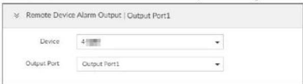
Step 2 Select a remote device and alarm output port.
You can select multiple alarm output ports.
Step 3 (Optional) Repeat Step 1–Step 2, and link multiple remote alarm output devices.
6.4.1.8 Access
Set access control function. When there is an alarm, system can trigger the corresponding access control device to open door and close door.

Make sure that access control device has been added. See "3.4.2 Adding Remote Device" for detailed information.
Step 1 Click Actions and select Access.
Figure 6-48 Access

Step 2 Select access control device.

Not all models support this function.
Step 3 (Optional) Repeat Step 1–Step 2, and link multiple access control devices.
6.4.1.9 Voice Prompt
Set voice prompt function. When there is an alarm, system can play the selected audio file.
Step 1 Click Actions and select Voice Prompt.
Figure 6-49 Voice prompt

Step 2 In the File Name list, select the audio file that you want to play for this configured period.
Step 3 Set delay time.
- Play times: Select Play Times and enter the times to play the file. After the alarm event is ended, system will continue to play the voice file according to the play times.
- Duration: Select Duration and enter the delayed play duration. After the alarm event is ended, system will continue to play the voice file according to the duration.
6.4.1.10 Smart Tracking
Alarm is triggered when a tripwire or intrusion behavior is detected. If smart tracking action is configured, the PTZ camera automatically rotates to the target view to track it.

● Smart tracking is only available for AI by Camera.
● Smart tracking is only available on the multi-sensor panoramic camera + PTZ camera.
On the event configuration page, select Actions > Smart Tracking to enable the action.
6.4.1.11 Report Alarm
Click Actions and then select Report Alarm to enable this function. Where there is an alarm, the system reports the alarm to alarm center.

Make sure that alarm center has been enabled. For details, see "6.3.2.8 Alarm Center".
6.4.1.12 Audio and Light Alarm
Set audio and light alarm for IVS detection. When there is an alarm, the system associates with the remote device to perform audio and light actions.

Audio and light alarm is available when AI by camera is used for IVS detection and the camera supports this function.
Step 1 Click Actions and select Camera Audio and Remote Warning Light.
Figure 6-50 Camera audio
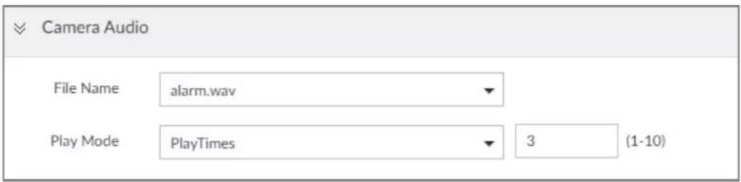
Figure 6-51 Remote warning light
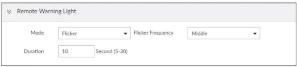
Step 2 Configure the parameters.
Table 6-18 Audio and light alarm parameters
| Parameter Description | ||
| Camera Audio | File Name | Select the audio file to be played when an alarm is triggered. |
| Play Mode Set the play | times of audio file. | |
| Remote Warning Light | Mode | Select Flicker or Always on. |
| Flicker Frequency | When Flicker is selected as Mode, set the flicker frequency. | |
| Duration | Set how long the warning light flickers or keeps on after an alarm is triggered. | |
6.4.2 Local Device
Set EVS alarm event, including abnormal event, device offline alarm, AI plan, and local device alarm.
6.4.2.1 One-click Disarming
Disarm alarm linkage actions as needed to avoid interference caused by alarms.
Step 1 Click 🎨 or click + on the configuration page, and then select EVENT.
Step 2 Select the root node in the device tree.
Step 3 Select Overview > Disarming.
Figure 6-52 Disarming
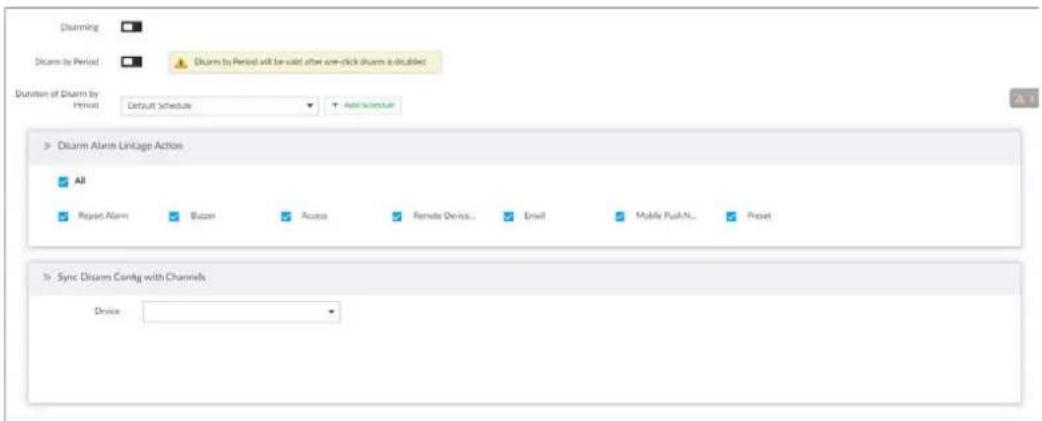
Step 4 Click □ to enable disarming.
Step 5 Cancel selecting alarm linkage actions as needed. The actions are selected by default.
Step 6 (Optional) Configure disarming by period.
1) Click □ to enable disarming by period.
2) Click Add Schedule to specify disarming schedule. The alarm linkage actions remain armed during unscheduled periods.
3) Click Apply.

After disarming by period is enabled, one-click disarming is disabled automatically.
Step 7 Configure sync disarming configuration with channels.
1) Click the drop-down list in the Sync Disarm Config with Channels section. The devices that support one-click disarming or disarming by period are displayed.
2) Select the device that you want to synchronize the disarming configuration with.
Step 8 Click Save.
6.4.2.2 Abnormal Event
Set the alarm mode when an abnormal event occurs.
The Device supports HDD, storage error, network, fan and power fault alarm.
Table 6-19 Abnormal event description
| Name Description | |
| No HDD | System triggers an alarm when there is no HDD. It is enabled by default. |
| Disk health exception | System triggers an alarm when HDD malfunctions. It is enabled by default. |
| Storage error | System triggers an alarm in case of HDD error, RAID degrade, RAID broken, and storage pool error. It is enabled by default. |
| Storage full | System triggers an alarm when the used storage space reaches the pre-defined threshold. It is disabled by default.The alarm is valid only when the storage mode is set asStopon theLocalHard Diskpage. |
| Storage pool error | System triggers an alarm when an error occurs in the storage pool. |
| RAID exception | System triggers an alarm in case of RAID exception. It is disabled by default. |
| Low quota space | System triggers an alarm when the quota space is insufficient, It is enabled by default. |
| Video frame loss | System triggers an alarm when the frame loss occurs in the recorded video. It is enabled by default. |
| IP conflict | System triggers an alarm when its IP address conflicts with IP address of other device in the same LAN. It is enabled by default. |
| MAC conflict | System triggers an alarm when its MAC address conflicts with MAC address of other device in the same LAN. It is enabled by default. |
| Lock in | System triggers an alarm when an account login error has reached the threshold. At the same time, system locks current account. It is disabled by default.Go to theSecuritypage to set account error threshold. See "6.7.3 Safety Protection" for detailed information. |
| Security exception | System triggers an alarm when a security exception occurs. It is enabled by default. |
| Fan speed alarm | When EVS fan speed is abnormal, system triggers an alarm. It is enabled by default. |
| Power fault | System triggers an alarm when EVS power supply is abnormal. It is disabled by default. |
| Share service | System triggers an alarm when share service is abnormal. It is enabled by default. |
| Temperature | System triggers an alarm when the temperature of the Device lower than 0 °C or higher than 95 °C. It is enabled by default. |
| SSD health exception | System triggers ana alarm when an error occurs on the SSD. |
Here we use no HDD for example. For other events, the setting steps are similar. See the actual page for detailed information.
Step 1 Click 🎨, or click + on the configuration page, and then select EVENT.
Step 2 Select the root node in the device tree.
Step 3 Select Abnormal Event > No HDD.
Figure 6-53 No HDD
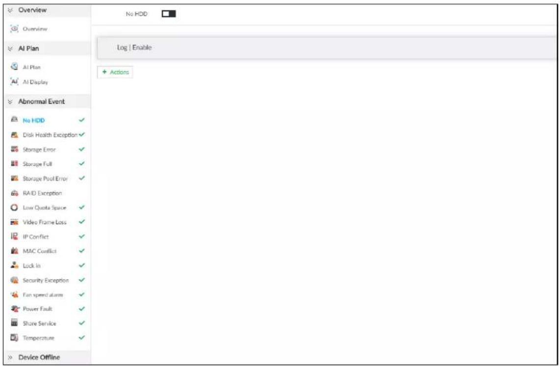
Step 4 Click □ to enable no HDD alarm function.
Step 5 Click Actions to set alarm actions. See "6.4.1 Alarm Actions" for detailed information.
Step 6 Click Save.
6.4.2.3 Offline Alarm
Set EVS network offline alarm. If you have not set offline alarm for a specified remote device, once the remote device is disconnected from the system, system adopts EVS alarm strategy to trigger an alarm.
Step 1 Click 🎨, or click + on the configuration page, and then select EVENT.
Step 2 Select the root node in the device tree on the left.
Step 3 Select Device Offline > Device Offline.
Figure 6-54 Offline alarm
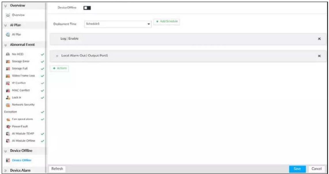
Step 4
Click to enable device offline alarm.
Step 5 Click Deployment Time to select schedule from the drop-down list.
After setting deployment period, system triggers corresponding operations when there is a motion detection alarm in the specified period.
- Click View Schedule to view detailed schedule settings.
- If the schedule is not added or the added schedule does not meet actual needs, click Add Schedule. See "6.9.3 Schedule" for detailed information.
Step 6 Click Actions to set alarm actions. See "6.4.1 Alarm Actions" for detailed information.
Step 7 Click Save.
6.4.2.4 Configuring AI Plan
Configure AI detection result display strategy of EVS. If you have not set AI display settings for current remote device, the remote device inherits AI display mode of EVS.
6.4.2.4.1 Viewing AI Plan
After adding remote device, on EVS, obtain AI detection type and status of the remote device.
On the EVENT page, select the root node in the device tree on the left. Select AI Plan > AI Plan. The AI Plan page is displayed. See Figure 6-55.
After installing the AI module, and the remote device supports AI detection, and you have enabled the AI detection function, you can view channel name of the remote device on the corresponding AI detection panel.

indicates that AI by Camera is enabled.
Figure 6-55 AI plan
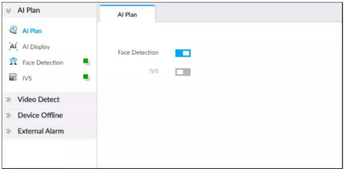
6.4.2.4.2 Setting AI Display
Set the property that shall be displayed in rule box and feature property panel. View AI detection result through smart preview, and support to display face, human and vehicle.

Take the procedure of configuring face detection AI display as an example. For other AI detection functions, the procedures are similar.
Step 1
Click

or click

on the configuration page, and then select EVENT.
Step 2
Select the root node in the device tree on the left.
Step 3
Select AI Plan > AI Display > Face.
Figure 6-56 Face
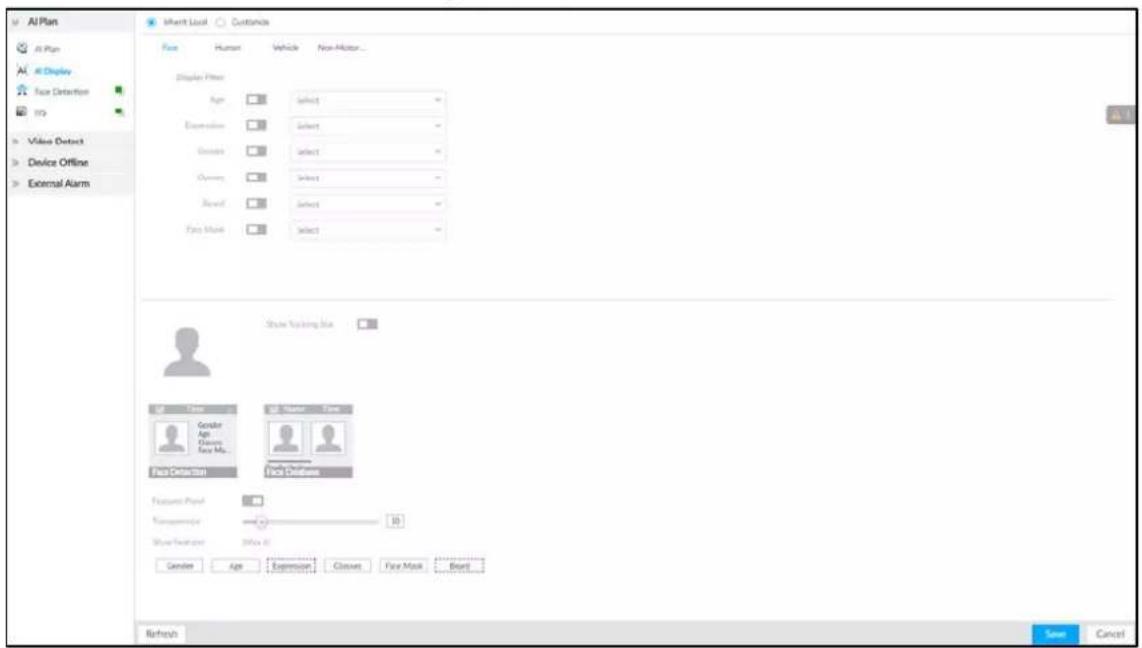
Step 4 Configure display filter information.
After setting filter criteria, only the qualified detection result will be displayed. For example, enable Age, and then select youth from the drop-down list. The tracking box and the features panel only display the human face of the youth age.
1) Click □ to enable corresponding filter type.
2) Set display filter criteria.
Click to set the filter color.
Step 5 Click □ in the right of Show Tracking Box to enable.
After enabled, when the system detects face or human, tracking box will be shown beside the face or human in the view window.
Figure 6-57 Tracking box
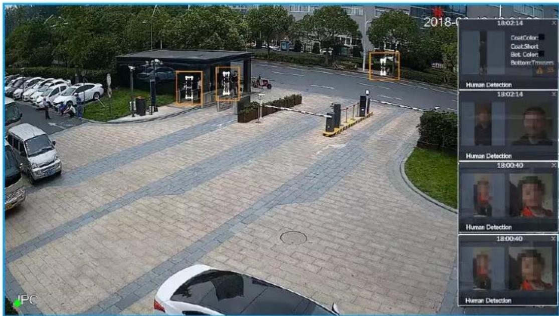
Step 6 Click ☐ in the right of Features Panel to enable, and select the features that shall be displayed on the LIVE page.
After enabled, there is a features panel on the right side of the view window. See Figure 6-58.
- Drag to adjust features panel transparency. The higher the value, the more transparent the features panel.
- System supports maximum 4 features. System has checked four features by default. To select other features, cancel the selected features, and then select the ones you need.
- Click √ to display the features panel on the LIVE page, including face detection panel and face DB panel.
Figure 6-58 Features panel
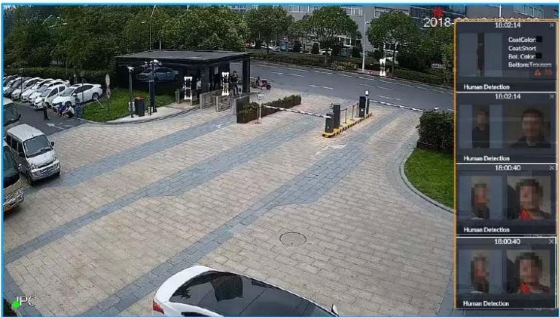
Step 7 Click Save.
6.4.3 Remote Device
Set alarm actions of remote device, including video detection alarm, offline alarm and AI plan of remote device.

The parameters might be different depending on the model you purchased.
6.4.3.1 Video Detect
Video detection function adopts the PC visual, image and graphical processing technology to analyze the video image and check there is considerable changes on the video. Once there are considerable video changes (such as there is any moving object, or the video is blurred), system triggers corresponding alarm event.
6.4.3.1.1 Configuring Video Motion
After analyzing video, system can generate a video motion alarm when the detected moving target reaches the sensitivity you set here.
Step 1 Click 🎨, or click + on the configuration page, and then select EVENT.
Step 2 Select remote device in the device tree on the left.
Step 3 Select Video Detect > Video Motion.
Figure 6-59 Video motion
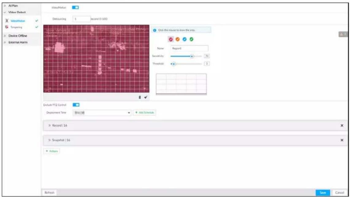
Step 4 Click to enable video motion detection.
Step 5 Set parameters.
Table 6-20 Motion detect parameters description
| Parameters Description | |
| Debouncing | System only records one alarm event during the debouncing period. |
| Exclude PTZ control | After enabling exclude PTZ control, system does not trigger an alarm when you are manually control the PTZ.It is for PTZ camera only. |
Step 6 Set motion detection region.
System supports maximum four detection zones. After setting, once there is an alarm from any of these four zones, the remote device triggers an alarm.
1) Click motion detection zone icon

2) On the surveillance video, press and hold on the left button of mouse to select detection zone.
- Select the motion detect zone you have drawn. Click 📋 to delete the zone.
- Click to clear the zone you have drawn.
3) Set parameters.
Table 6-21 Description of zone parameters
| Parameters | Description |
| Name | Set detection zone name to distinguish different zones. |
| Sensitivity | Drag to set sensitivity.The higher the sensitivity is, the easier it is to trigger an alarm. At the same time, the false alarm rate increases as well. Usually we recommend the default value. |
| Threshold | Drag to adjust threshold.Once the detected percentage (the percentage of target to detection zone) is equivalent to or larger than the specified threshold, system triggers alarm. For example, the threshold is 10. Once the detected target occupies the 10% of the detection zone, system triggers an alarm. |
Step 7 Click Deployment Time to select schedule from the drop-down list.
After setting deployment period, system triggers corresponding operations when there is a motion detection alarm in the specified period.
- Click View Schedule to view detailed schedule settings.
- If the schedule is not added or the added schedule does not meet actual needs, click Add Schedule. See "6.9.3 Schedule" for detailed information.
Step 8 Click Actions to set alarm actions. See "6.4.1 Alarm Actions" for detailed information.
Step 9 Click Save.
6.4.3.1.2 Tampering
Once something tampers the surveillance video, and the output video is in one color, the system can generate an alarm.
Step 1 Click 🎨, or click + on the configuration page, and then select EVENT.
Step 2 Select remote device in the device tree on the left.
Step 3 Select Video Detect >Tampering.
Figure 6-60 Tampering
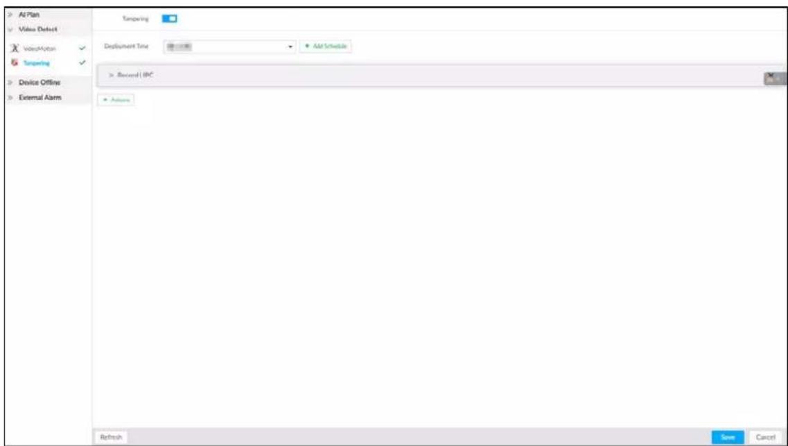
Step 4 Click □ to enable tampering alarm.
Step 5 Click Deployment Time to select schedule from the drop-down list.
After setting deployment period, system triggers corresponding operations when there is a motion detection alarm in the specified period.
- Click View Schedule to view detailed schedule settings.
- If the schedule is not added or the added schedule does not meet actual needs, click Add Schedule. See "6.9.3 Schedule" for detailed information.
Step 6 Click Actions to set alarm actions. See "6.4.1 Alarm Actions" for detailed information.
Step 7 Click Save.
6.4.3.2 Offline Alarm
When the remote device and the EVS are disconnected, system can trigger an alarm.
Step 1 Click 🎨, or click + on the configuration page, and then select EVENT.
Step 2 Select a remote device in the device tree on the left.
Step 3 Select Device Offline > Device Offline.
Figure 6-61 IPC offline
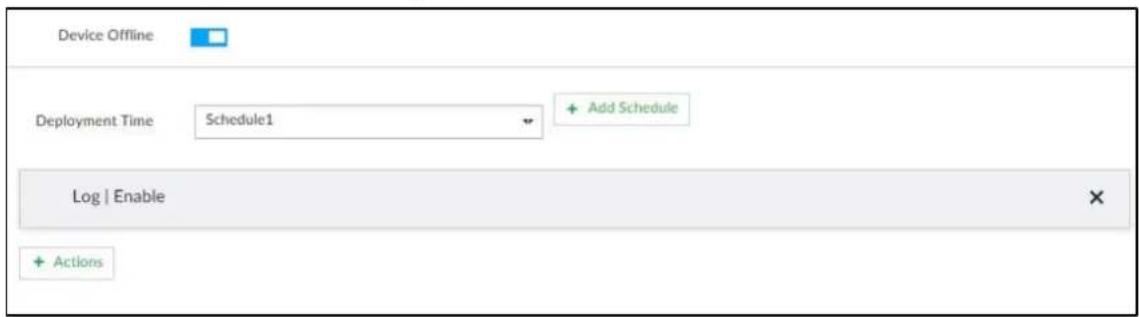
Step 4 Click □ to enable offline alarm.

The device offline alarm is enabled by default. You can skip this step.
Step 5 Click Deployment Time to select schedule from the drop-down list.
After setting deployment period, system triggers corresponding operations when there is a device offline alarm in the specified period.
- Click View Schedule to view detailed schedule settings.
- If the schedule is not added or the added schedule does not meet actual needs, click Add Schedule. See "6.9.3 Schedule" for detailed information.
Step 6 Click Actions to set alarm actions. See "6.4.1 Alarm Actions" for detailed information.
Step 7 Click Save.
6.4.3.3 IPC External Alarm
Set IPC alarm input event, so that when there is an alarm input to the IPC, IPC uploads the alarm to the Device. If the camera has multiple IO channels, you can set the alarm input event for each of them as you might need.
Step 1 Click 🎨, or click + on the configuration page, and then select EVENT.
Step 2 Select a remote device in the device tree on the left.
Step 3 Select External Alarm > IO1.
The IO1 page is displayed. See Figure 6-62.
Figure 6-62 I01
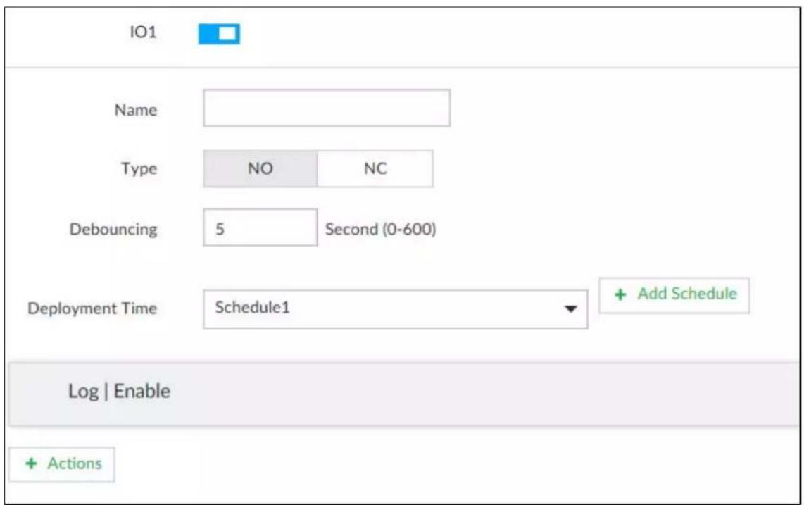
Step 4 Click to enable the alarm.
Step 5 Set parameters.
Table 6-22 Local alarm parameters description
| Parameters Description | |
| Name | In the Alarm name box, enter a name for the alarm. |
| Type | Select alarm input device type. Both NO and NC are supported. |
| Debouncing | The system records only one event during this period. |
Step 6 Click Deployment Time to select schedule from the drop-down list.
After setting deployment period, system triggers corresponding operations when there is a motion detection alarm in the specified period.
- Click View Schedule to view detailed schedule settings.
- If the schedule is not added or the added schedule does not meet actual needs, click Add Schedule. See "6.9.3 Schedule" for detailed information.
Step 7 Click Actions to set alarm actions. See "6.4.1 Alarm Actions" for detailed information.
Step 8 Click Save.
6.4.3.4 Thermal Alarm

- Alarm types vary depending on the models of thermal cameras.
- Make sure that configurations of thermal detections such as fire detection and temperature detection have been done on the thermal camera.
Supports the following thermal camera alarms.
Table 6-23 Thermal alarms
| Function Description | |
| Fire alarm | When the thermal camera detects a fire, the alarm signal is transmitted to the EVS device, which performs an alarm linkage action. |
| Temperature alarm | When the thermal camera detects that the temperature is above or below the threshold value, the alarm signal is transmitted to the EVS device, which performs an alarm linkage action. |
| Temperature difference alarm | When the thermal camera detects a temperature difference greater than the set value, the alarm signal is transmitted to the EVS device, and the EVS device will perform an alarm linkage action. |
| Hot spot alarm | When the maximum temperature detected by the thermal camera is higher than the set value, the alarm signal is transmitted to the EVS device, and the EVS device will perform an alarm linkage action. |
| Cold spot alarm | When the lowest temperature detected by the thermal camera is below the set value, the alarm signal is transmitted to the EVS device, and the EVS device will perform an alarm linkage action. |
This section uses the procedure of configuring fire alarm as an example. The procedures are similar.
Step 1 Click

or click

on the configuration page, and then select EVENT.
Step 2 Select the root node in the device tree on the left.
Step 3 Select Thermal Alarm > Fire Alarm.
Step 4 Click Deployment Time to select schedule from the drop-down list.
After setting deployment period, system triggers corresponding operations when there is a motion detection alarm in the specified period.
- Click View Schedule to view detailed schedule settings.
- If the schedule is not added or the added schedule does not meet actual needs, click Add Schedule. See "6.9.3 Schedule" for detailed information.
Step 5 Click Actions to set alarm actions. See "6.4.1 Alarm Actions" for detailed information.
Step 6 Click Save.
6.5 Storage Management
Click 📋 or click + on the configuration page, select STORAGE. Manage storage resources (such as recording file) and space, so you can use and improve utilization ratio of storage space.

The system supports pre-check and routine inspection function, displays health status on the Storage page, so you obtain real-time status of device and avoid data loss.
- Pre-check: During device operation, the system automatically detects disk status in case of change (start, and insert the disk).
- Routine inspection: The system carries out routine inspection of the disk continuously. During device operation, the disk might go wrong due to service life, environment and other factors.
6.5.1 Local Hard Disk
The local hard disk refers to the HDD installed on the system. On this page, you can view HDD space (free space/total space), temperature (centigrade/Fahrenheit), HDD information and so on.
Click 📷, or click + on the configuration page, and then select STORAGE > Storage Resource > Local Hard Disk. There is a corresponding icon near the HDD name after you create the RAID and hot spare HDD.
• : RAID HDD.
- : Global hot spare HDD.
- : Invalid HDD of RAID group.

Slight difference might be found on the user interface.
Figure 8-65 HDD
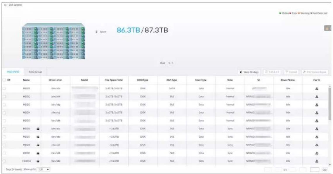
6.5.1.1 Viewing S.M.A.R.T
S.M.A.R.T is Self-Monitoring Analysis and Reporting Technology. It is a technical standard to check HDD drive status and report potential problems. System monitors the HDD running status and compares with the specified safety value. Once the monitor status is higher than the specified value, system displays alarm information to guarantee HDD data security.

Check one HDD to view S.M.A.R.T information at one time.
On the Local Hard Disk page, select a HDD, and then click S.M.A.R.T. The S.M.A.R.T page is displayed. Check whether the HDD status is OK or not. If there is any problem, fix it in time.
Figure 8-66 S.M.A.R.T
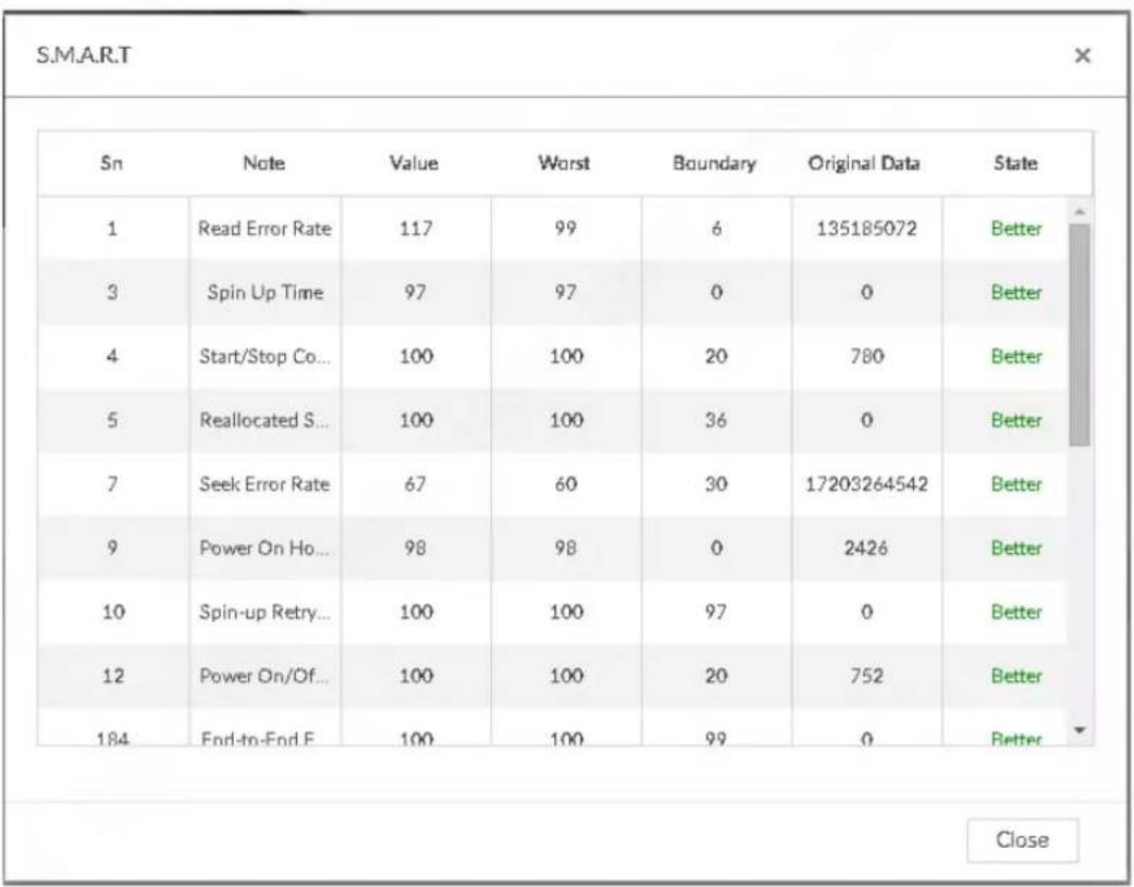
6.5.1.2 Format

- Formatting HDD will clear all data on the HDD. Be careful!
• Hot spare HDD cannot be formatted.
To format the selected HDDs, enter the Local Hard Disk page, select one or more HDD(s), and click
Format.
6.5.1.3 File System Repair
Once you cannot mount the HDD or you cannot properly use the HDD, you can try to use the File System Repair function to fix the problem.
Enter the Local Hard Disk page, select one or more HDD(s) you cannot mount, and click File System Repair, you can repair the selected file system of the corresponding HDD(s). The repaired HDD can work properly or to be mounted.
6.5.1.4 Viewing RAID Group
Click 📋, or click + on the configuration page, and then select STORAGE > Storage Resource > Local Hard Disk > RAID Group. You can view free space, RAID type, working mode and status of RAID group.
Figure 8-68 RAID group
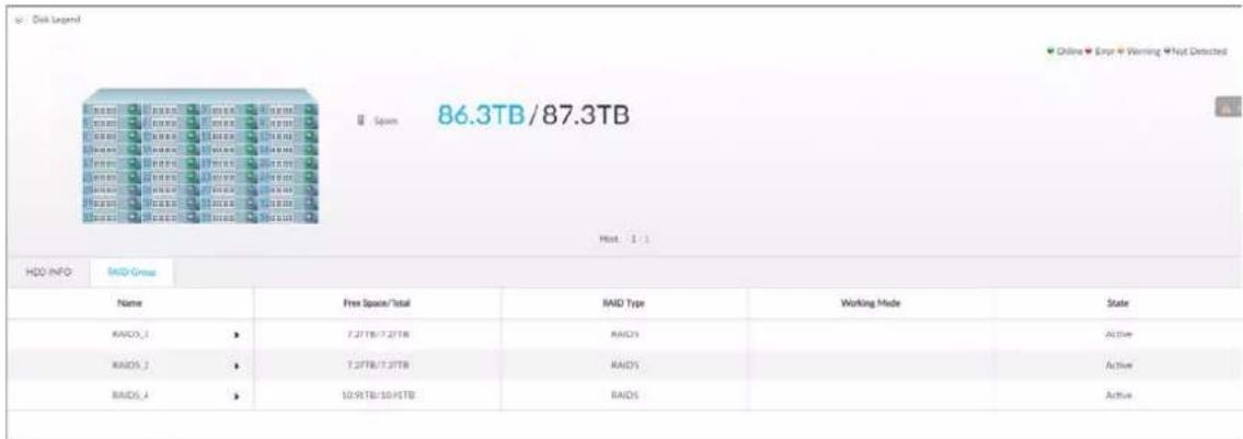
- Click ▶ next to the RAID name to display the RAID member list, and then you can view RAID member details.
- Point to the Status column, and then click ⓘ to display the Details page and view RAID group details.
6.5.2 RAID
RAID (Redundant Array of Independent Disks) is a data storage virtualization technology that combines multiple physical HDD components into a single logical unit for the purposes of data redundancy, performance improvement, or both.

- The Device supports RAID0, RAID1, RAID5, RAID6, RAID10, RAID50 and RAID60. See "Appendix 2 RAID" for detailed information.
- You are recommended to use enterprise HDD when you are creating RAID, and use surveillance HDD for single-HDD mode.
6.5.2.1 Creating RAID
RAID has different levels such as RAID5, and RAID6. Different RAID levels have different data protection, data availability and performance levels. Create RAID according to your actual requirements.

Creating RAID operation will clear all data on these HDD. Be careful!
Step 1 Click ⚙, or click + on the configuration page, and then select STORAGE > Storage Resource > RAID > RAID.
Figure 8-69 RAID (1)

Step 2 Click Add.
Figure 8-70 Create RAID (1)
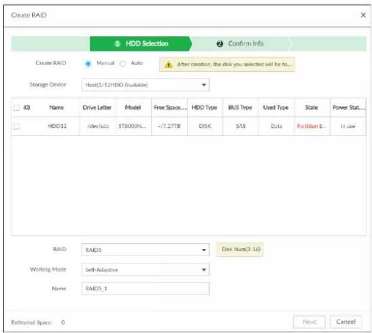
Step 3 Set RAID parameters.
Select RAID creation type according to actual situation. It includes Manual RAID and Auto RAID.
Manual RAID: System creates a specified RAID type according to the selected HDD amount.
1) Select Manual RAID.
2) Select HDD you want to use.
3) Set parameters.
Table 8-24 Manual creation parameters description
| Parameters Description | |
| Storage Device | Select storage device of the HDD and select the HDD you want to add to the RAID.Different RAID types need different HDD amounts. |
| RAID | Select a RAID type you want to create. |
| Working Mode | Set RAID resources allocation mode. The default setup is self-adaptive.Self- adaptive means the system can automatically adjust RAID synchronization speed according to current business load. When there is no external business, the synchronization speed is at high speed. When there is external business, the synchronization speed is at low speed.Sync first: Allocate resources to RAID synchronization first.Business first: Allocate resources to business first.Load- Balance: Allocate resources to business and RAID synchronization equally. |
| Name Set RAID name. |
Auto: System creates RAID5 according to the HDD amount.
1) Select Auto.
Figure 8-71 Create RAID (2)
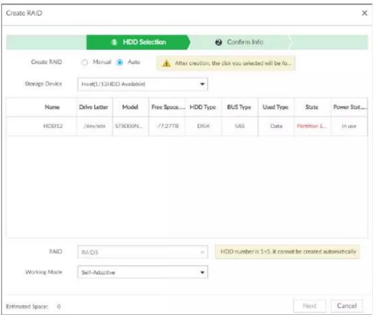
2) Set parameters.
Table 8-25 Auto parameters description
| Parameters Description | |
| Storage Device | Select storage device of the HDD. |
| Working mode | Set RAID resources allocation mode. The default setup is self-adaptive.Self-adaptive means the system can automatically adjust RAID synchronization speed according to current business load. When there is no external business, the synchronization speed is at high speed. When there is external business, the synchronization speed is at low speed.Sync first: Allocate resources to RAID synchronization first.Business first: Allocate resources to business first.Load- Balance: Allocate resources to business and RAID synchronization equally. |
Step 4 Click Next.
Step 5 Confirm the information.

If the input information is wrong, click Back to set RAID parameters again.
Step 6 Click Create.
System begins to create RAID. It displays RAID information after creation.
Figure 8-74 RAID (2)

Related Operations
After creating RAID, view RAID disk status and details, clear up RAID, and repair file system.
Table 8-26 RAID operation
| Name Operation | |
| View RAID HDD status | View RAID HDD space and status. |
| View RAID details | Click 1 to view RAID detailed information. |
| File System Repair | Once you cannot mount the RAID or you cannot properly use the RAID, you can try to use repair file system function to fix.Enter RAID page, select one or more RAID(s) you cannot mount, click File System Repair, you can repair the selected file system of the corresponding RAID(s). The repaired RAID can work properly or to be mounted. |
| Modify Working Mode | Select one or more RAIDs, and then click Working Mode to modify the working mode. |
| Format RAID | Enter RAID page, select one and more RAID groups. Click Format to format the selected RAID. Formatting RAID is to clear all data on the RAID and cancel the RAID group.Please be careful. Formatting RAID is to clear all data on the RAID and cancel the RAID group.Please be careful. |
| Delete RAID | Enter RAID page, select one and more RAID groups. Click Delete to delete the selected RAID. Deleting RAID is to clear all data on the RAID and cancel the RAID group.Please be careful. Deleting RAID is to clear all data on the RAID and cancel the RAID group.Please be careful. |
Figure 8-75 RAID details
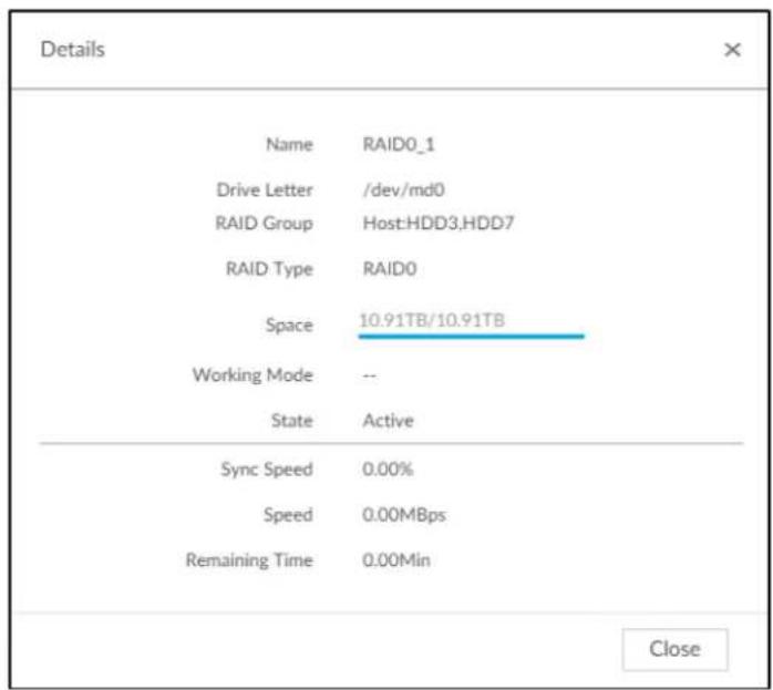
6.5.2.2 Creating Hot Spare HDD
When an HDD of the RAID group is malfunctioning, the hot spare HDD can replace the malfunctioning HDD.
Step 1 Click 🎨 or click + on the configuration page, and then select STORAGE > RAID > Hot spare.
Figure 8-76 Hot spare (1)
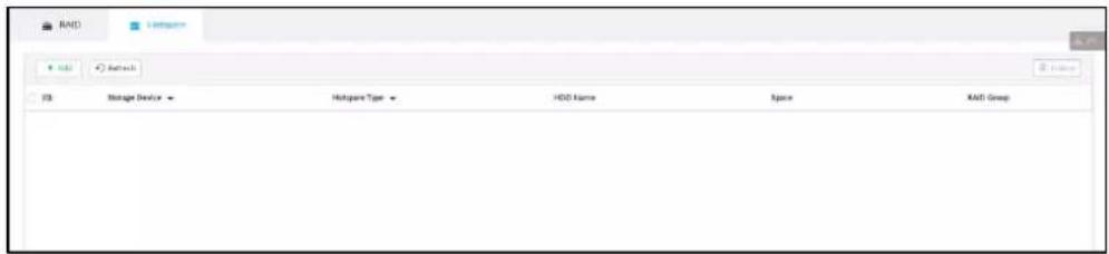
Step 2 Click Add.
Figure 8-77 Global hot spare
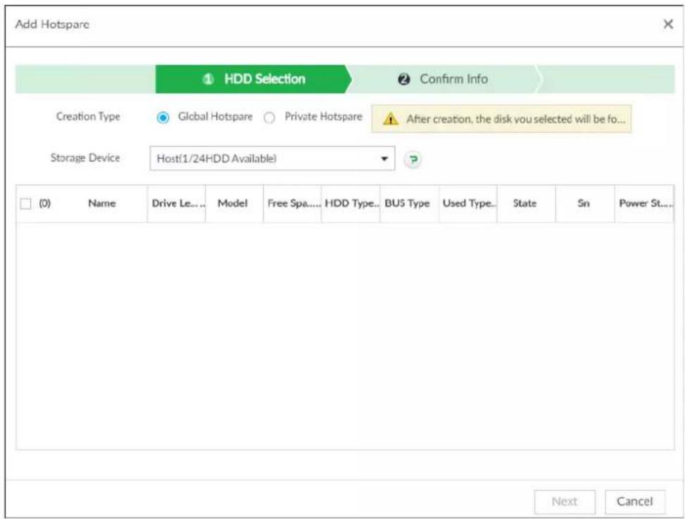
Figure 8-78 Private hot spare
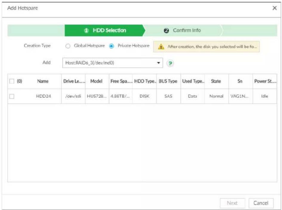
Step 3 Select hot spare creation type.
- Global hot spare: Create hot spare for all RAID.
- Private hot spare: Select Private Hot spare and Add it to a RAID group. The private hot spare HDD is for a specified RAID group.
Step 4 Select one or more HDD(s) and then click Next.
Figure 8-79 Confirm info
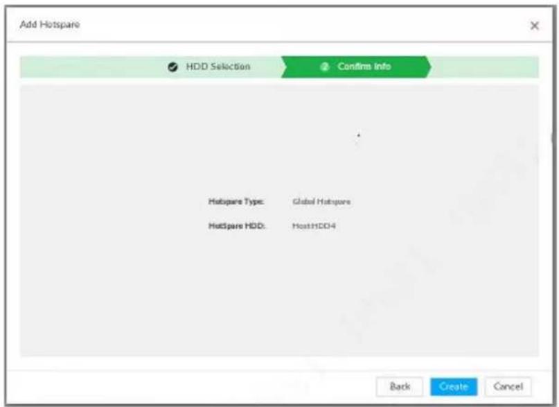
Step 5 Confirm info.

Click Back to select hot spare HDD(s) again if you want to change settings.
Step 6 Click Create to save settings.
System displays the added hot spare HDD information.
Figure 8-80 Hot spare (2)


Select a hot spare HDD and then click Delete, it is to delete hot spare HDD.
6.5.3 Network Hard Disk
Network hard disk is a network-based online storage service that stores device information in the network hard disk through the iSCSI protocol.
6.5.3.1 iSCSI Application
View network hard disk usage, including remaining capacity, and hard disk status.
Click 📋, or click + on the configuration page, and then select STORAGE > Storage Resource > Network Hard Disk > iSCSI Application.
Figure 6-63 iSCSI application
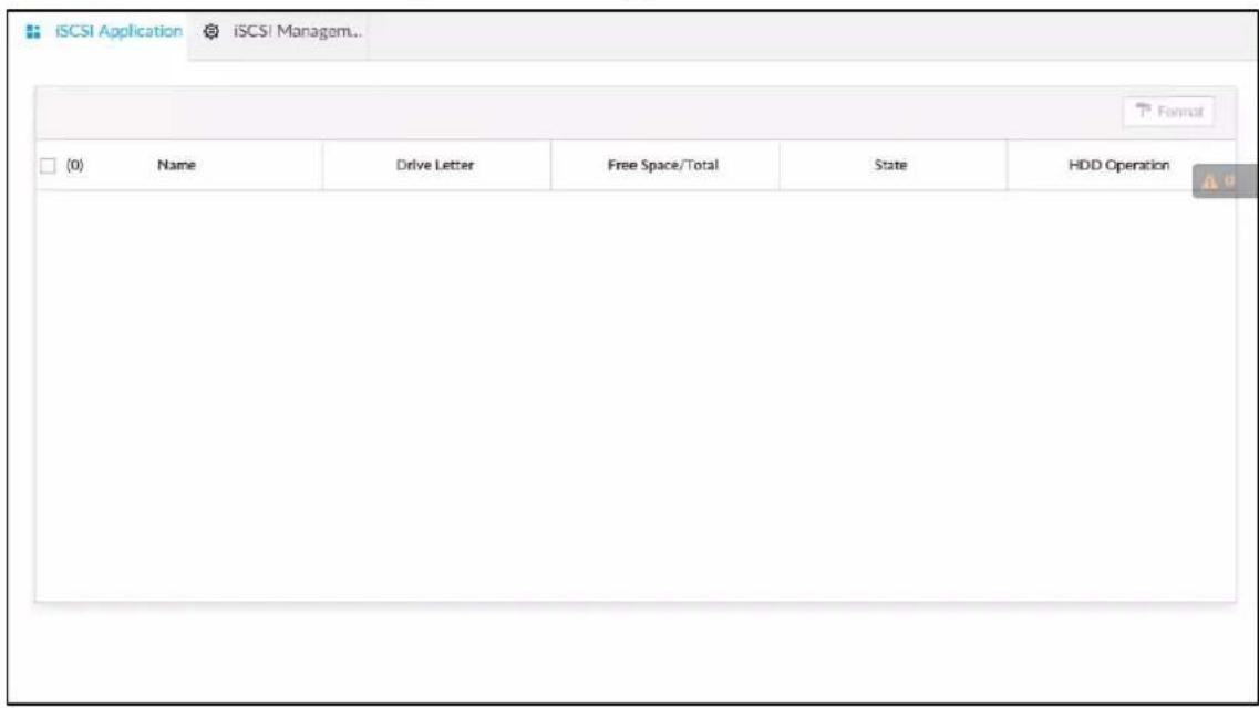
- Select a network hard disk, and then click Format to format the disk. Formatting your hard disk will erase all data from your hard disk, so do it carefully.
- Click the HDD Operation column, and then you can select an HDD operation permission type.
Read/Write: Read, edit, add, and delete data of this disk.
Read Only: One can only read data of this disk.
6.5.3.2 iSCSI Management
Set up the network disk through iSCSI and map the network disk to the Device so that the Device can use the network disk for storage.

- iSCSI is a networked storage technology that runs SCSI protocols on the IP network.
● The network disk mapped to the Device cannot be used to create a RAID.
- Make sure that service has been enabled on the iSCSI server and the server has provided the shared file directory.
Step 1 Click 📋, or click + on the configuration page, and then select STORAGE > Network Hard Disk > iSCSI Management.
Figure 6-64 Network hard disk
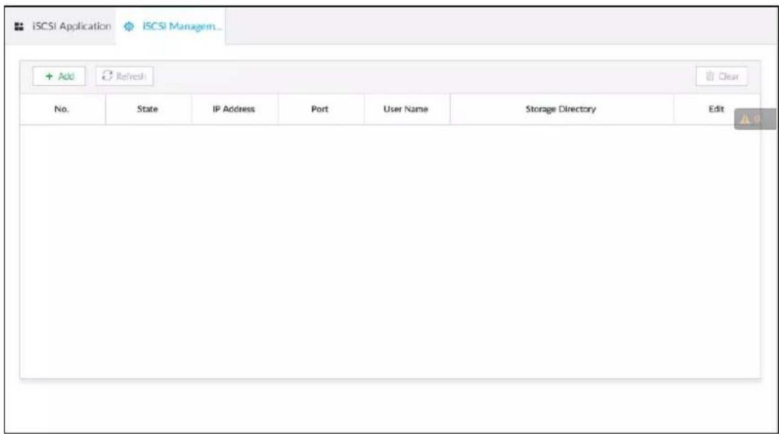
Step 2 Click.

Figure 6-65 Add iSCSI
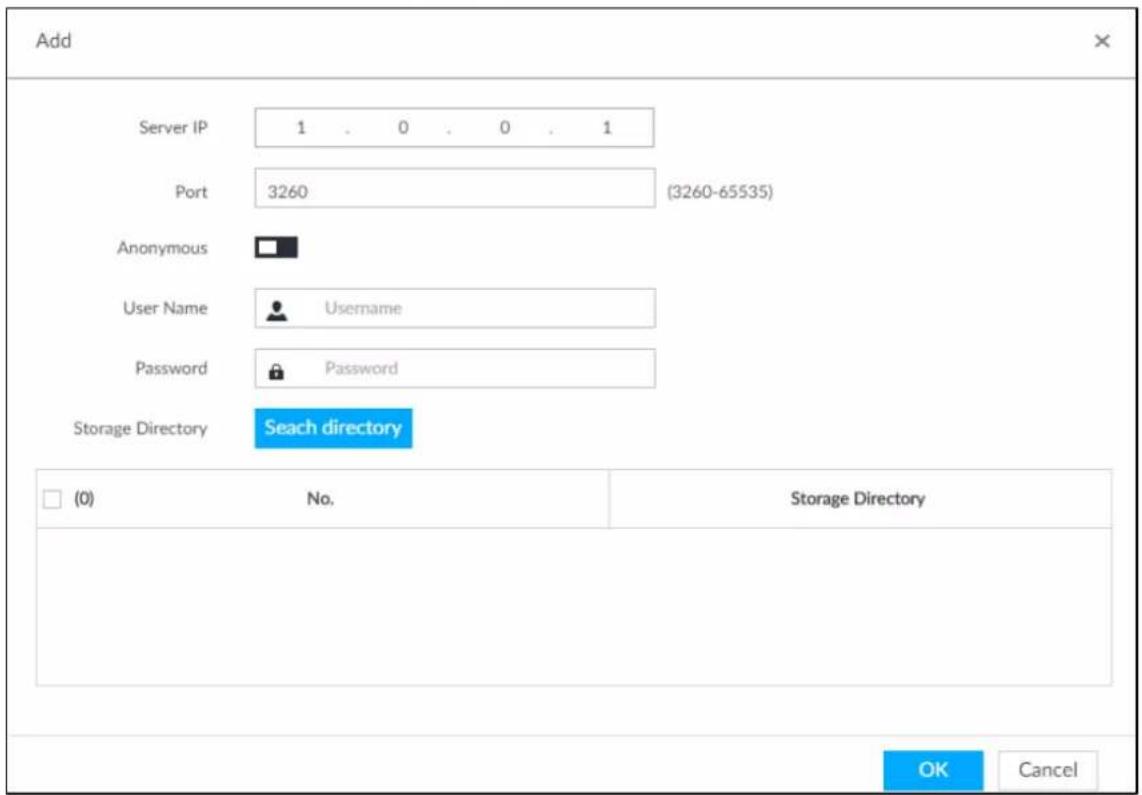
Step 3 Set parameters.
Table 6-24 Network hard disk parameters
| Parameters Description | |
| Server IP | Enter iSCSI server IP address. |
| Port | Enter iSCSI server port number. It is 3260 by default. |
| Anonymous | If iSCSI server has no permission limitation, you can select anonymous login. |
| Username | If access permission has been limited when creating the shared file directory on the iSCSI server, you need to enter username and password. |
| Password | |
| Storage Directory | Click Search Directory to select the storage directory.The storage directory is generated when the shared file directory is being created on the iSCSI server. Each directory is an iSCSI disk. |
Step 4 Click OK.
The added network disk is displayed.

- Click to delete a disk; click Refresh to refresh the disk list.
- On the Disk Group page, you can configure network disk groups.
6.5.4 FTP/SFTP
Configure FTP/SFTP server for video and picture storage. This section uses configuring SFTP as an example.

- FTP is unencrypted transmission, while SFTP is encrypted transmission. You are recommended to use SFTP.
- When creating SFTP user, you need to configure write permission of SFTP folder. Otherwise, you cannot upload files.
- You need to purchase or download SFTP tool and install it on your PC.
Step 1 Click 🎨, or click + on the configuration page, and then select STORAGE > SFTP.
Figure 6-66 SFTP
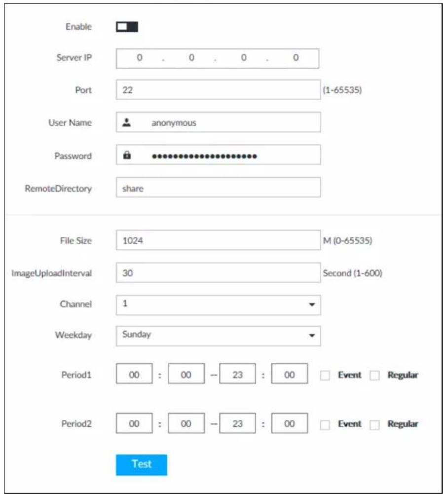
Step 2 Click □ to enable SFTP.
Step 3 Set parameters.
Table 6-25 SFTP parameters
| Parameters Description | |
| Server IP SFTP server | IP address. |
| Port | It is 22 by default. |
| User Name | The username and password of the SFTP server. |
| Password | You can keep the username as anonymous, so as to log in in an anonymous way. |
| Remote Directory | Enter the SFTP directory.The system automatically establishes folders according to the IP, time, and channel information if you leave the directory empty.Enter the directory name, and then the system creates a folder accordingly under the root directory of SFTP and generates different folders according to the IP, time, and channel information. |
| File Size | Set the size of the file to be uploaded.If the to-be-uploaded file is larger than the threshold, the system uploads only part of it (the same size with the threshold).If the to-be- uploaded file is smaller than the threshold, the system uploads the whole of it.If the threshold you have set is 0, the system uploads the whole of the file. |
| Image Upload Interval | Set the upload intervalof images. |
| Channel | Set the channel number of the video file. |
| Weekday | Select the day, the time period, and file type (event file or regular file). The system uploads files in the time periods as you have set. |
| Period | |
| Test | Click Test to test the SFTP connection. |
Step 4 Click Save.
6.6 Video Recording
6.6.1 Storage Mode
Allocate disks or RAID groups to different disk groups, and store video and image to specified disk group.
6.6.1.1 Setting Disk Group
Disk and created RAID group are allocated to group 1 by default. You can allocate disk and RAID group to other groups according to your actual needs.
The default number of disk group is the same as the maximum number of HDD that EVS supports.
Step 1 Click 🔒, or click + on the configuration page, and then select STORAGE > VIDEO
RECORDING > Storage Mode > Disk Group.

- The value (such as 1) next to the group name refers to the number of HDD and RAID group in the disk group. If instead, 1 is displayed, it means no available HDD or RAID group in the disk group, but there is video or image stored in the disk group.
● indicates picture storage. ■ indicates video storage.
Step 2 Click a disk group.
Figure 8-84 Disk group
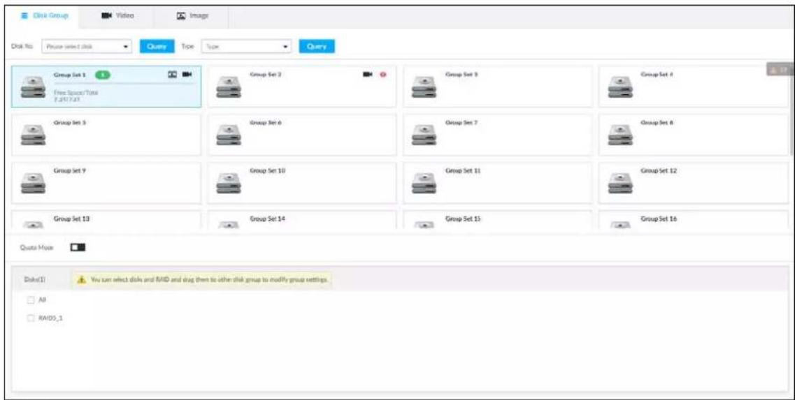
Step 3 Select HDD or RAID group from Disks, and then drag the HDD or the RAID group to another disk group.
Disk grouping takes effect immediately.

Select All to select all the HDDs and RAID groups of the disk group.
After configuring disk groups, you can also view which disk group the selected disk, video or picture belongs to.
Table 8-28 Disk group functions
| Function Description | |
| View the disk group of a disk, video or picture | Click , select a disk or RAID group, and then click Query to search for the disk group that the selected disk or RAID group belongs to. |
| View disk groups of video or image | Select Video or Image from , and then-click query to search for disk groups of the selected type. |
6.6.1.2 Setting Video/Image Storage
Videos/images of all channels are stored in disk group 1 by default. You can store the videos/images in different disk groups according to actual needs. Two methods are available to set video/image storage.

This section uses storing video for example. To store images, the procedure is similar.
6.6.1.2.1 Method 1: Selecting Disk Group
Step 1 Click 📋, or click + on the configuration page, and then select STORAGE > VIDEO RECORDING > Storage Mode > Video.
Figure 8-85 Video
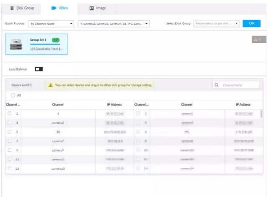
Step 2 Select filtering way from the Batch Process drop-down list.
- By Channel Name: Select channel according to the channel name.
- By Logical Channel No.: Select channel that is connected to EVS. In this case, Start Channel No. and End Channel No. need to be configured.
Step 3 In the Select Disk Group drop-down list, select target disk group.

In the drop-down list, only disk group with available HDD or RAID group is displayed.
Step 4 Click OK.
Disk grouping takes effect immediately.
6.6.1.2.2 Method 2: Dragging Channel
Step 1 Click 🎨, or click + on the configuration page, and then select STORAGE > VIDEO RECORDING > Storage Mode > Video.
Step 2 Click a disk group.
The linked channels of the disk group are displayed in Device List.

- Only disk group with available HDD or RAID group or linked channel is displayed.
- The value (such as 1) next to the group name refers to the number of HDD and RAID group in the disk group. If instead, 0 is displayed, it means no available HDD or RAID group in the disk group, but there is video or image stored in the disk group.
Figure 8-86 Device list
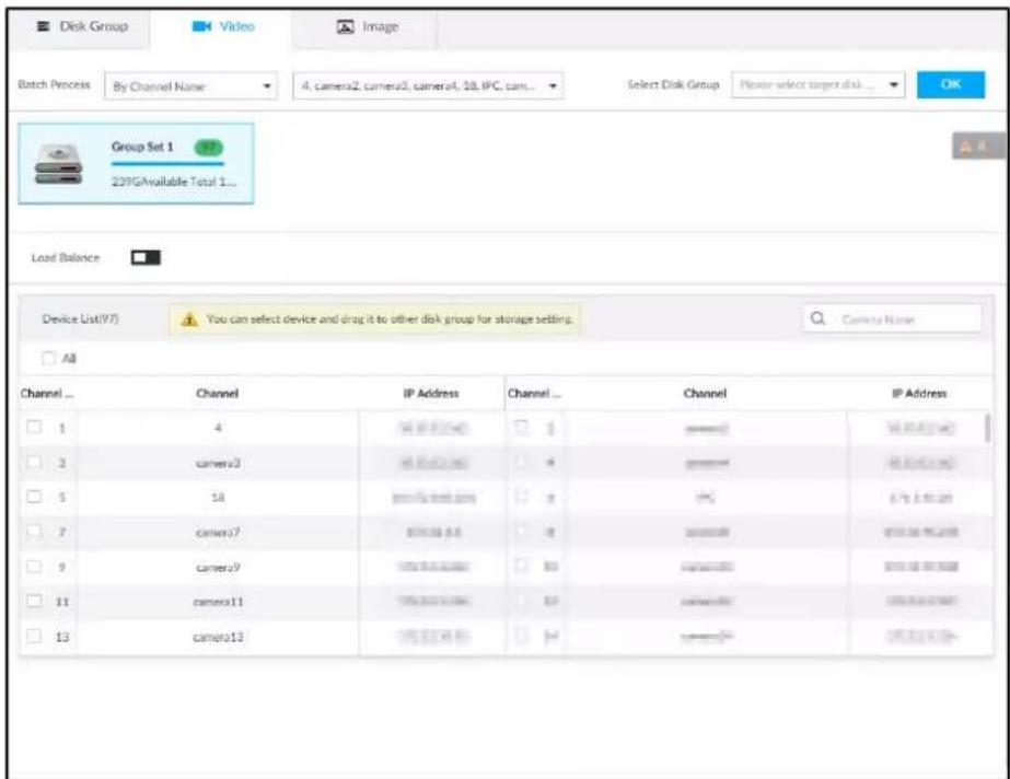
Step 3 (Optional) Click □ to enable load balance, and then the icon turns into blue. To disable it, click it again, and then the icon turns into gray.
- After load balance is enabled, if one disk group has no usable disk, the video of all channels that belong to this disk group will be stored into all the usable disk groups.
- When load balance is not enabled, if one disk group has no usable disk, the video of all channels that belong to this disk group will be stored in another usable disk group.
Step 4 Select a channel from the Device list, and drag the channel to the target disk group. Disk grouping takes effect immediately.
6.6.1.3 Enabling Quota Mode
Enable quota mode to set the storage quota for each device.
Step 1 Click 🎨, or click + on the configuration page, and then select STORAGE > VIDEO RECORDING > Storage Mode > Disk Group.
Step 2 Click to enable quota mode.
Step 3 On the Video tab, click in the Device list to set the video quota for a device. Set the storage capacity and reference bit rate, and then the system calculates record duration.
Figure 6-67 Edit video quota
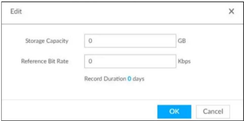
Step 4 On the Image tab, click in the Device list to set the quota for a device. Set the storage capacity and reference bit rate, and then the system calculates the number of images that can be stored.
Figure 6-68 Edit image quota
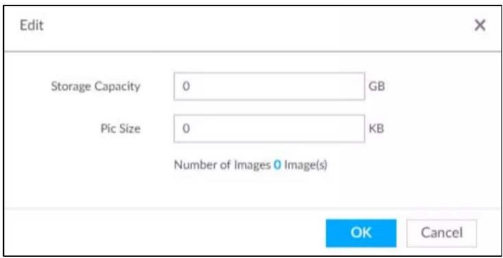
Step 5 On the Quota tab, you can view the total and used quota of each device.
Figure 6-69 Quota information
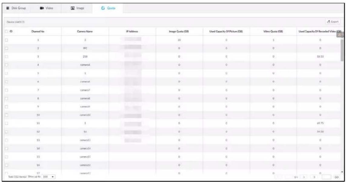
6.6.2 Recording Schedule
Configure recording modes and schedules for channels.
6.6.2.1 Recording Mode
Configure recording modes for channels.
Step 1 Click 📋, or click + on the configuration page, and then select STORAGE > VIDEO RECORDING > Schedule.
Step 2 Find the camera for which you want to configure a recording schedule, select the recording methods for the stream types.
• means that the type is selected.
- Substream1 and Substream2 cannot be enabled at the same time.
• Auto: Records automatically according to the schedule.
- Manual: Records around the clock and does not respond to the recording schedule.
- Close: No recording and does not respond to the recording schedule.
Step 3 Select a recording method.
Step 4 (Optional) click □ to disabled the recording schedule configuration of the selected channel
Step 5 Click Save.
Figure 8-87 Recording mode
| DEVICE INFO | Record Mode | Time plan | |||||||||||||
| Main Stream | Substream1 | Substream2 | |||||||||||||
| Channel No. | Channel Name | Auto | Manual | Close | Auto | Manual | Close | Auto | Manual | Close | General | Record Errors | Pre-Record Ground | Setting | |
| 1 | 27 | ||||||||||||||
| 2 | Channel2 | ||||||||||||||
| 3 | PC | ||||||||||||||
6.6.2.2 Recording Schedule
Configure video and picture recording schedules so the Device records and captures pictures as configured in the specified period.
Step 1 Click 🎨, or click + on the configuration page, and then select STORAGE > VIDEO RECORDING > Schedule.
Step 2 Click ⚙, set a recording schedule, and then click OK.
Figure 8-88 Set a recording schedule
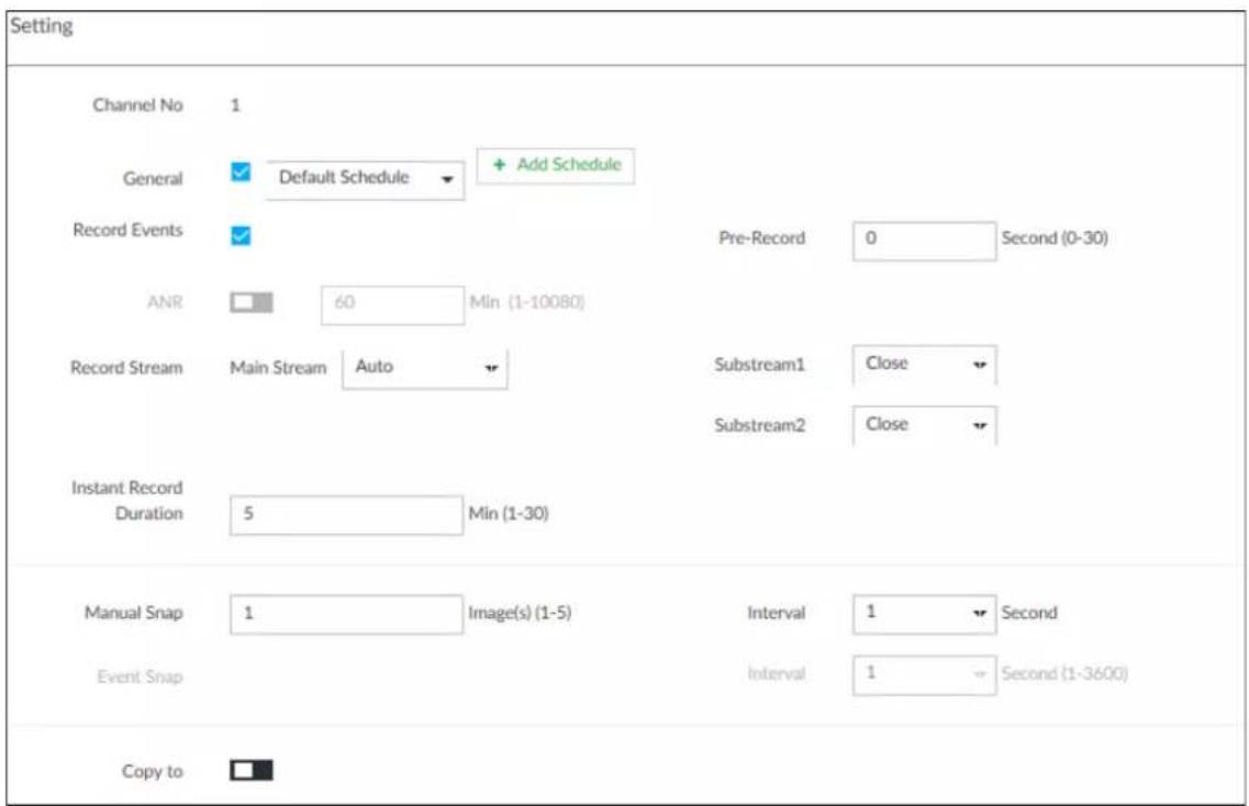
Table 6-26 Parameters of recording schedule
| Parameter Description | |
| General | Select the checkbox and then click the drop-down list to select a schedule to enable the function. The Device records video according to the selected schedule. |
| If the schedule is not added or the added schedule does not meet actual needs, click Add Schedule. See "6.9.3 Schedule" for detailed information. | |
| Record Events | Enable Record Events and then set the pre-recording time. When an alarm triggers linkage recording, the Device records the video according to the pre-recording time. For example, if the pre-recording time is 10 seconds, the Device starts recording 10 seconds before the event occurs. |
| Pre-Record | |
| ANR | Automatic Network Replenishment. When ANR is enabled (by clicking ), the Device will download videos recorded by IPC and stored on camera SD card during network disconnection. Enter the time length of the video to be downloaded from IPC. The Device will download only the defined length of video even if the disconnection is longer.To use this function, make sure that the SD card is installed and recording enabled on the camera. |
| Record Stream Select stream types and recording modes. | |
| Instant Record Duration | The duration of instant recording. After starting instant recording on the LIVE page, if you do not stop recording, it will automatically stop after the defined duration. |
| Manual Snap | The number of image captures. |
| Event Snap | The number of images for each manual capture action. Enter a value to specify the number of seconds between each image. |
| Copy to | Copy the current settings to other channels. |
Step 3 Click Save.
6.6.3 Basic
Configure the storage mode when the disk space is used up and the automatic deletion of expired files.
6.6.3.1 Setting Storage Mode
Configure the storage mode when there is no more disk space available.
Step 1 Log in to PCAPP.
Step 2 Click 📋, or click + on the configuration page, and then select STORAGE > VIDEO RECORDING > Storage Mode.
Step 3 Set storage mode when the HDD free space is less than the acceptable threshold.
The acceptable threshold for storage space is 4% of the total space within the range of 150 GB to 200 GB.
- Overwrite: When HDD free space is less than the acceptable threshold, the Device continues to record and the new videos overwrite the oldest files.

Data will be overwritten in the Overwrite mode. Back up in time.
- Stop: When HDD free space minus the acceptable threshold is less than the defined free space alarm rate of the total space, an alarm is triggered and the Device continues recording until the HDD free space is less than the acceptable threshold.
Figure 6-70 Storage mode
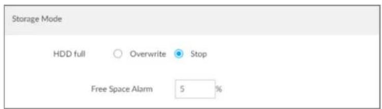
Step 4 Click Save.
6.6.3.2 Setting Automatic File Deletion
You can enable the Device to automatically delete files older than a certain number of days.
Step 1 Log in to PCAPP.
Step 2 Click ⚙, or click + on the configuration page, and then select STORAGE > VIDEO RECORDING > Storage Mode.
Step 3 Set automatic file deletion.
- Never: The Device does not delete files automatically.
- Customize: The Device automatically deletes files older than the configured number of days.

The deleted files cannot be recovered.
Figure 6-71 Delete expired files

Step 4 Click Save.
6.6.4 Record Transfer
When the Device and an IPC are disconnected, the IPC continues to record and stores the recording in the SD card. After the network is recovered, the Device will download the recording during the disconnection from the IPC.
Two ways for record transfer after the network recovers.
- Automatic download: After the network recovers, the Device automatically downloads the recording in the set time period.
- Manual download: If ANR is not enabled when you set the recording schedule, after the network recovers, the Device can not automatically download the recording during the disconnection, but the user can manually create the download task.
Step 1 Click ⚙, or click + on the configuration page, and then select STORAGE > VIDEO RECORDING > Record Transfer.
Step 2 Click Add.
Figure 8-90 Add
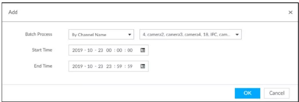
Step 3 Select By Channel Name or By Channel No. in the Batch Process drop-down list.
Step 4 Set time period of the video to be searched.
Step 5 Click OK.
The transfer progress is displayed.

Select a transfer task, click Delete to delete it. A task in progress cannot be deleted.
6.7 Security Strategy
Click 🤗 or click + on the configuration page, select SECURITY.
Set security strategy to guarantee device network and data safety. It includes HTTPS, set host IP access rights, enable network security protection.

HTTPS function is for web interface and PCAPP only. See the actual interface for detailed information.
Figure 6-72 Security center
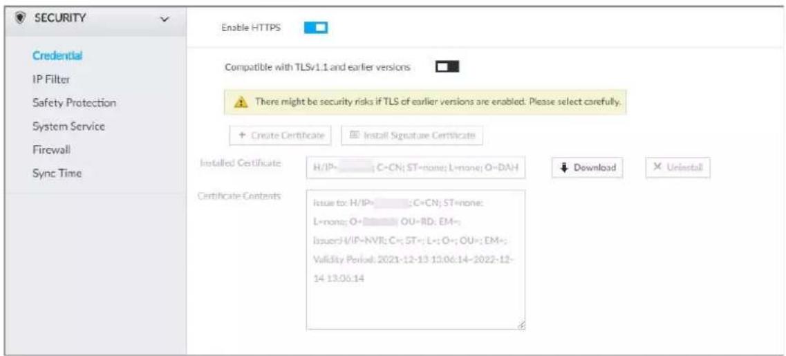
6.7.1 HTTPS
HTTPS can use the reliable and stable technological means to guarantee user information and device security and communication data security. After installing the certificate, you can use the HTTPS on the PC to access the Device.

You are recommended to enable HTTPS service. Otherwise, you might risk data leakage.
6.7.1.1 Installing Certificate
There are two ways to install the certificate.
• Manually create a certificate and then install.
- Upload a signature certificate and then install.
6.7.1.1.1 Installing the Created Certificate
Install the created certificate manually. It includes creating the certificate on the Device, downloading and installing the certificate on the PC.

- Create and install root certificate if it is your first time to use HTTPS or you have changed device IP address.
- After creating server certificate and installing root certificate, download and install root certificate on the new PC, or download the certificate and then copy to the new PC.
Step 1 Click 🎨, or click + on the configuration page, and then select SECURITY > Credential.
Step 2 Create certificate on the Device.
1) Click Create certificate.
Figure 6-73 Create certificate
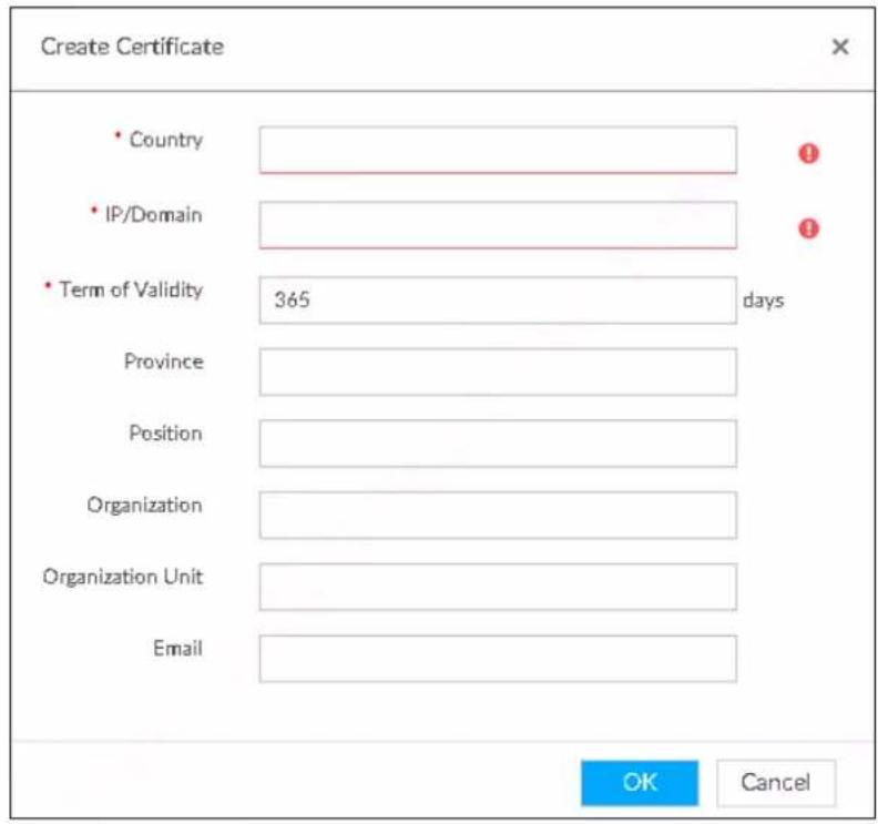
2) Set country, IP/domain, valid date and so on.

● Country, IP/domain, and valid date are required items. Other items are optional.
- IP/domain shall be the Device IP or the domain.
3) Click OK.
System begins to install certificate, and then displays certificate information after the installation.
Step 3 Download certificate.
1) Click.
2) Click Save File to select file saved path.
3) Click Save.
System begins downloading certificate file.
Step 4 Install root certificate on the PC.
1) Double-click the certificate.
System displays Open file-security warning page.
2) Click Open.
3) Click Install Certificate.
4) Follow the prompts to import the certificate.
System goes back to Certificate page.
Step 5 Click OK to complete certificate installation.
Figure 6-74 Installed certificate
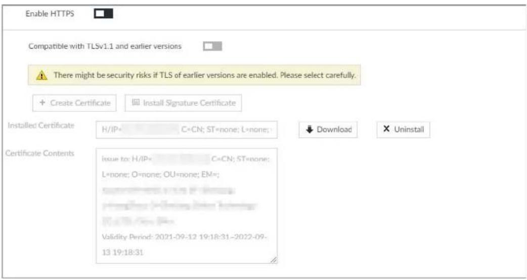
6.7.1.1.2 Installing Signature Certificate
Upload signature certificate to install.
Preparation
Before installation, make sure that you have obtained safe and valid signature certificate.
Procedure
Step 1 Click 🎨, or click + on the configuration page, and then select SECURITY > Credential.
Figure 6-75 Credential
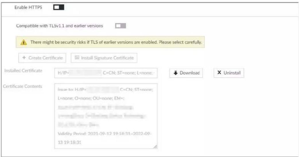
Step 2 Click Install Signature Certificate.
Step 3 Click Browse and then select certificate and credential file.
Step 4 Click Install.
System begins to install certificate, and then displays certificate information after the installation.
Step 5 Install the root certificate on the PC.

This root certificate is the one obtained with signed certificate.
6.7.1.2 Enabling HTTPS
After you install the certificate and enable HTTPS function, you can use the HTTPS on the PC to access the Device.
Step 1 Click 🎨, or click + on the configuration page, and then select SECURITY > Credential.
Step 2 Click to enable HTTPS function.
Step 3 Click ir enable Compatible with TLSv1.1 and earlier versions.

TLS (Transport Layer Security) provides privacy and data integrity between two communications application programs.
Figure 6-76 Credential
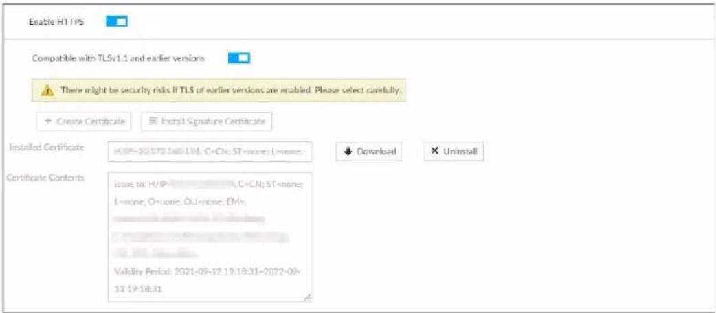
6.7.2 Configuring Access Permission
Set the specified IP addresses to access the Device, to enhance device network and data security. Step 1 Click 🎨, or click + on the configuration page, and then select SECURITY > IP Filter. Figure 6-78 IP Filter  Step 2 Select IP access rights. - Allow all access: It is to allow all IP addresses in the same IP segment to access the Device. - Reject access list: It means the IP address in the list cannot access the Device. - Allow access list: It means the IP address in the list can access the Device. Step 3 Add IP host.  The following steps are to set reject access list or allow access list. 1) Click Add. Figure 6-79 Add  2) Select Add Type, and set IP address or MAC address of IP host. - Single IP: Enter host IP address. - IP segment: Enter IP segment. It can add multiple IP addresses in current IP segment. • MAC: Enter MAC address of IP host. 3) Click OK to add the IP host. System displays added IP host list.  \- Click Add to add more IP hosts. \- Click to edit the IP host. \- Select an IP host and then click Delete to delete. Step 4 Click Save.6.7.3 Safety Protection
Set the login password lock strategy once the login password error has exceeded the specified threshold. System can lock current IP host for a period of time. Step 1 Click 📋, or click + on the configuration page, and then select SECURITY > Safety Protection. Figure 6-80 Safety protection (1)  Step 2 Click to enable security protection function. \- Remote: When you are using web interface, PCAPP to access the Device remotely, once the login password error has exceeded the threshold, system locks the IP host for a period of time. \- Local: When you are accessing local menu of the Device, once the login password error has exceeded the threshold, system locks the account for a period of time. Step 3 Set lock strategy according to the actual situation. Step 4 Click Save. Once the IP host has been locked, you can view the locked IP host on the list. Select an IP host and then click Unlock, or click the 🔒 of the corresponding IP host to unlock. Step 5 (Optional) Click Login lock event to go to the Event page where you can select Abnormal Event > Lock in to configure a Lock in event.6.7.4 Enabling System Service Manually
Enable system services for third-party access. Step 1 Click 📄, or click + on the configuration page, and then select SECURITY > System Service. Figure 6-81 System service  Step 2 Enable or disable system service according to your actual situation. Table 6-27 System service| System service Description | |
| SSH | After enabling this function, you can access EVS through SSH protocol to carry out system debugging and IP configuration. This function is disabled by default.You are recommended to disable this function. Otherwise there might be security risks. |
| System service Description | |
| Mobile Phone Push | After enabling this function, you can access EVS with mobile phone client, to receive information from EVS.You are recommended to disable this function. Otherwise there might be security risks. |
| CGI Enable | After this function is enabled, third-party platform can connect EVS through CGI protocol.You are recommended to disable this function. Otherwise there might be security risks. |
| ONVIF Enable | After this function is enabled, other devices can connect EVS through ONVIF protocol.You are recommended to disable this function. Otherwise there might be security risks. |
| Run Log | After enabling it, you can view system running logs in Intelligent Diagnosis > Run Log. |
| Password Expires in | Configure the password expiration interval. The Device prompts you to change the password when the password expires. |
| Audio/Video Transmission Encryption | When this function is enabled, stream transmission will be encrypted.You are recommended to enable this function. Otherwise you might risk data leakage. |
| RTSP over TLS | Enable this function to encrypt stream transmission.You are recommended to enable this function. Otherwise you might risk data leakage. |
| Private Protocol Authentication Mode | Select a private protocol authentication mode between security mode and compatible mode. Security mode is recommended. |
6.7.5 Configuring Firewall
Enhance network and data security by prohibiting Ping and half-connection. - PING Prohibited: When PING Prohibited is enabled, the Device does not respond to Ping requests. - Anti Half Connection: When Anti Half Connection is enabled, and the Device can provide service normally under half-connection attack. Step 1 Click  or click  on the configuration page, and then select SECURITY > Firewall. Figure 6-82 Firewall  Step 2 Click □ to enable PING Prohibited or Anti Hal Connection. Step 3 Click Save.6.7.6 Configuring Time Synchronization Permission
Configure permissions of time synchronization actions from other devices or servers. Step 1 Click 🎨, or click + on the configuration page, and then select SECURITY > Synch Time. Figure 6-83 Sync time  Step 2 Click □ to enable time synchronization restriction. Step 3 Click the Allowlist or Blocklist tab. - Hosts in the allowlist have the permission to synchronize time of the Device. - Hosts in the blocklist cannot synchronize time of the Device. Step 4 On the Allowlist page or the Blocklist page, add hosts. 1) Click Add. Figure 6-84 Add a host  2) Select an IP version, and then enter an IP address. 3) Click OK. Step 5 Click Save. You can also perform the following functions. Table 6-28 Other functions| Function Description | |
| Edit IP address | Click to edit IP address. |
| Delete IP address | Click to delete a host from the list. |
| Configure IP address permission | Click the corresponding of each host, so as to enable the allowlist or blocklist configuration for the host.Click to disable the allowlist or blocklist configuration for the host. |
6.8 Account Management
Device account adopts two-level management mode: user and user group. You can manage their basic information. To conveniently manage the user, we recommend the general user authorities shall be lower than high-level user authorities.  \- To ensure device safety, enter correct login password to operate on the Account page (for example, add or delete user). \- After a correct login password is entered on Account page, if you do not close Account page, you can do other operations directly. If you close the page and enter it again, you shall enter the correct login password again.6.8.1 User Group
Different users might have different authorities to access the Device. You can divide the users to different groups. It is easy for you to maintain and manage the user information. ● System supports maximum 64 user groups. User group name supports maximum 64 characters. ● System has two default user groups (read-only): admin and ONVIF. • Create new user group under the root.Adding User Group
Step 1 Click 🎨, or click + on the configuration page, and then select ACCOUNT. Step 2 Select the root node in the device tree on the left and then click at the lower-left corner. Figure 6-85 Input password  Step 3 Enter current user's login password, and then click OK. Figure 6-86 User group property  Step 4 Set parameters. Table 6-29 User group| Parameters Description | |
| Name | Set user group name.The name should consist of 1 to 64 characters and contain English letters, number and special characters. |
| Group name | Displays user group organization node. System automatically recognizes the group name. |
| Description | Enter user group description information. |
| User list | Displays user information of current group. |
Step 5 Select user authority.
1) Click Authority tab. Figure 6-87 Authority  2) Set user group authorities according to actual situation. • : means it has the corresponding authority. \- Check the box at the top of the authority list (such as (0) Authority Control) to select all authorities of current category. Step 6 Click Save.Deleting user group
 - Before you delete a user group, delete all users of current group first. User group cannot be restored after being deleted. Be cautious. - Admin and ONVIF user cannot be deleted. Step 1 Click  or click  on the c Step 2 Select user group and click .  Figure 6-88 Enter password  Step 3 Enter current user's login password, and then click OK. The following prompt page is displayed. Step 4 Click OK.6.8.2 Device User
The device user is to access and manage the Device. System default administrator is admin. It is to add a user and then set corresponding authorities, so that the user can access the resources within its own rights range only.  User authorities adopt the user group authorities settings. It is read-only.Procedure
Step 1 Click 🎨, or click + on the configuration page, and then select ACCOUNT. Step 2 Select admin user group or other newly added user group, and then click 📋+ at the lower-left corner. Figure 6-89 Enter password  Step 3 Enter current user's login password, and then click OK. Figure 6-90 Property  Step 4 Set parameters. Table 6-30 User management| Parameters Description | |
| Name | Set username.The name ranges from 1 to 31 characters. It can contain English letters, numbers and special characters (_@). |
| Group name | Displays user organization node. System automatically identifies it. |
| Password | In the new password box, enter the new password and enter it again in the Confirm Password box.The password should consist of 8 to 32 non-blank characters and contain at least two types of characters among uppercase, lowercase, number, and special character (excluding '";: &). Usually we recommend the strong password. |
| ConfirmPassword | |
| Description | Describe the user. |
Related Operations
After adding a user, you can modify user information or delete the user. For details, see Table 6-31.  The user with account management authority can change its own and other users' information. Table 6-31 User operation| Name Operation | |
| Edit user information | Select a user from user list. The Property page of the user is displayed, and the user's login password and description information can be modified. |
| Delete User | ct a user from user list, and then click  to delete.Before deleting online user, shield the user first. For details, see "8.6 Network Care".User information cannot be restored after being deleted. Be cautious. to delete.Before deleting online user, shield the user first. For details, see "8.6 Network Care".User information cannot be restored after being deleted. Be cautious. |
6.8.3 Password Maintenance
Maintain and manage user's login password.6.8.3.1 Changing Password
Change user's login password.Changing Password of the Current User
Step 1
Click
 at the upper-right corner, and then select Change Password. Figure 6-92 Change password  Step 2 Enter old, new and confirmed password.  When you enter a character that is not allowed, 9 appears and the character will be deleted automatically. Step 3 Click OK.Changing Password of Other User
 Only Admin account supports this function. Step 1 Click 🎨, or click + on the configuration page, and then select ACCOUNT. Step 2 Select a user. Figure 6-93 Property Step 3 Click.
 Figure 6-94 Input password Step 4 Enter current user's login password, and then click OK.
Figure 6-95 Change password Step 5 Enter old, new and confirmed password.
Step 6 Click OK.6.8.3.2 Resetting Password
You can use email address to reset password once you forgot it.Enable password reset
Enable the password reset function, and then leave an email address for password reset. Step 1 Click 🎨, or click + on the configuration page, and then select ACCOUNT. The Account page is displayed. Step 2 Select the root node in the device tree on the left. The Password Reset page is displayed. Step 3 Click □ to enable the password reset function. Step 4 Enter an email address for resetting password. Step 5 Click Save.Reset password
 • Make sure that the password reset function is enabled. • Make sure that the email address for password reset is set. Step 1 Go to the login page of the Device. Figure 6-96 Login Step 2 Click Forgot Password?
- If you have not set the email address information, you cannot reset password. Contact your technical support for help. - If you have set the email address information, the following prompt is displayed. Figure 6-97 Prompt Step 3 Click OK.
The QR code page is displayed. Figure 6-98 Scan QR code  Step 4 Follow the on-screen instructions to obtain the security code. Enter the security code that you received in the security code box.  - You can get security codes twice by scanning the same QR code. If you need to get the security code once again, refresh the page. - Use the security code to reset the password within 24 hours; otherwise the security code becomes invalid.Step 5 Click Next.
The new password setting page is displayed. Figure 6-99 New password setting  Step 6 Set parameters. Table 6-32 Description of password parameters| Parameters Description | |
| User | The default username is admin. |
| Password | In the New Password box, enter the new password and enter it again in the Confirm Password box.The password should consist of 8 to 32 non-blank characters and contain at least two types of characters among upper case, lower case, number, and special characters (excluding '' ; : & and space). Enter a strong password according to the password strength indication. |
| ConfirmPassword | |
Step 7 Click Confirm Modify.
You can log in with the new password.6.8.4 ONVIF
When the remote device is connecting with the Device through ONVIF protocol, use the verified ONVIF account.  - System adopts three ONVIF user groups (admin, user and operator). You cannot add ONVIF user group manually. - You cannot add user under ONVIF group directly.Adding ONVIF User
Step 1 Click 🎨, or click + on the configuration page, and then select ACCOUNT. Step 2 Select user group under ONVIF. Figure 6-100 ONVIF  Step 3 Click at the lower-left corner of the Property page. Figure 6-101 Input password  Step 4 Enter the login password of current user, and then click OK. Figure 6-102 ONVIF property  Step 5 Set parameters. Table 6-33 ONVIF parameters description| Parameters Description | |
| User Name | Set ONVIF username.The name ranges from 1 to 31 characters. It can contain English letters, number and special character (_@.). |
| Group name | Displays user organization node. System automatically identifies it. |
| Password | Set ONVIF user password.The password should consist of 8 to 32 non-blank characters and contain at least two types of characters among upper case, lower case, number, and special characters (excluding '";: & and space). |
| ConfirmPassword | |
| Description | Enter ONVIF user description information. |
Delete ONVIF User
 Deleting the admin account is not supported. Step 1 Click 🎨, or click + on the configuration page, and then select ACCOUNT. Step 2 Select an ONVIF user and click 🎨. Figure 6-103 Input password  Step 3 Enter current user's login password, and then click OK. The following prompt page is displayed. Step 4 Click OK.6.9 System Configuration
Click 🎨 or click + on the configuration page, select SYSTEM. The SYSTEM page is displayed. Set system basic settings, such as general parameters, time, display parameter, schedule, and voice.6.9.1 Setting System Parameters
Set system language, standard, user logout time, virtual keyboard, and mouse moving speed. Step 1 Click 🎨, or click + on the configuration page, and then select SYSTEM > General > System. Figure 6-104 Configuresystem settings  Step 2 Set parameters. Table 6-34 System parameters description| Parameters Description | |
| Language | Set system language. |
| Standard | Select video standard.PAL is mainly used in China, Middle East and Europe.NTSC is mainly used in Japan, United States of America, Canada and Mexico.As a technical standard of processing video and audio signals, PAL and NTSC mainly differ in encoding, decoding mode and field scanning frequency. |
| User Logout Time | Set automatic logout interval for log-time inactivity. After auto logout, the user needs to log in again to operate.If you set asNo Logout, system does not automatically log out. |
| Sync Remote Device | Clickto enable the function. If enabled, the language, standard and time settings configured here will be synchronized to all the connected remote devices. |
| Standby Board Real-Time Transmission Service | After enabling this function, when the client requests real-time streams, streams will be transferred from the standby board first, and the pre-record of the standby board is enabled automatically to ensure data integretiy during main/sub switch. |
6.9.2 System Time
Set system time, and enable NTP function according to your need. After enabling NTP function, device can automatically synchronize time with the NTP server. Step 1 Click 🎨, or click + on the configuration page, and then select SYSTEM > General > Time. Figure 6-105 Time  Step 2 Set parameters. Table 6-35 System parameters description| Parameters Description | |
| Time | Set system date and time. You can set manually or set device to synchronize time with the NTP server.Manual Setting: Select Manual Setting and then set the actual date and time in the following two ways.Click , and then set the time and date in the calendar.Click Sync to synchronize device time with your PC.When using IE11, Google Chrome75 or Firefox61 and later versions, on the web interface of the Device, click Sync to synchronize both device time and time zone with the PC.When using earlier versions of browser, on the web interface of the Device, click Sync to synchronize only device time with PC.Sync with the Internet Time Server: Check the box and then enter NTP server IP address or domain, and then set Auto Sync Time Interval. |
| Time and Date Format | Set time and date display format. |
| Time Zone Set device | time zone. |
| Parameters Description | |
| Auto Time Synchronization | After enabling this function, EVS detects system time of remote device once in every interval. When time of remote device is inconsistent with EVS time, EVS will calibrate the time of remote device automatically. |
6.9.3 Schedule
Set schedule. When you are configuring alarm, record arm/disarm period, system can call the schedule directly. System only triggers the corresponding operations during the specified schedule.  Default schedule has been created by default. Default schedule is Always Effective, and cannot be modified or deleted. Step 1 Click 🎨, or click + on the configuration page, and then select SYSTEM > Schedule > Schedule. Figure 6-106 Schedule  Step 2 Add schedule. 1) Click.  The Add Schedule page is displayed. Figure 6-107 Adding schedule  2) Set schedule name. 3) Click OK to save the configuration. Step 3 Set valid time period. It includes Always Effective and Customize. Step 4 Set validity period of schedule.  • The step is for customized mode only. • Each calendar supports maximum 50 validity periods. - The blue area on the time bar means the validity period. On the time bar, you can: - Click the blue area, and is displayed. Drag to adjust the start time and end time of validity period. - Press the any blank space on the time bar, and drag to the right to add a validity period. - Click Clear to clear all validity periods of current schedule. - Select a validity period, and then click Delete to delete the period. Step 5 Click Save.  Select an added schedule, and then click to delete.6.10 Network Storage
Network storage is a storage technology based on IP network. After you create a storage pool, you can share your storage directory with other devices through iSCSI. Figure 6-108 Configuring network storage flowchart
graph TD
    A["Start"] --> B["Create Storage Pool"]
    B --> C["Create Share Account"]
    C --> D["Create Share Folder"]
    D --> E["Enable Share Service"]
    E --> F["End"]
6.10.1 Creating Storage Pool
Storage pool is a logical storage space after the storage device is virtualized. It is managed by the system, and can be composed of multiple actual disks or RAID. Network storage is one of the major means to realize storage virtualization.  Creating storage pool will format the disk. Step 1 Click 🎨, or click + on the configuration page, and then select Network Storage > Storage Pool. Figure 6-109 Storage pool  Step 2 Click Add. Figure 6-110 Create storage pool  Step 3 Name the pool, and then select a disk or RAID group.  By default, in the Device Name column, "sdx" (x ranges from a to z) is a disk, such as /dev/sda, and "mdx" (x is number) is a RAID group, such as /dev/md0. Step 4 Click OK. The confirmation dialogue box is displayed. Step 5 Click OK. The system starts to create storage pool.  • To delete a pool, click 📄. • To refresh the storage pool list, click Refresh.6.10.2 Managing Share Account
Use share account to access the shared folder. Step 1 Click 📁, or click  on the configuration page, and then select Network Storage > Share Account. Figure 6-111 Share account  Step 2 Click Add. Figure 6-112 Add user  Step 3 Set parameters. Table 6-36 Parameters description| Parameters | Description |
| User Name Name the user. | |
| Service Type | You can select ISCSI, FTP/SAMBA, ISCSI/FTP/SAMABA. |
| Password | Set a password for the user. |
| Confirm password | The password shall be 12-digit if the service type is iSCSI. |
| Remark | Set the remark information for identifying the user. |
6.10.3 Configuring Share Folder
Configure the share folders that other users can access remotely. Step 1 Click 🎨, or click + on the configuration page, and then select Network Storage > Share Folder. Figure 6-113 Share folder  Step 2 Click Add. Figure 6-114 Add (iSCSI)  Step 3 Set parameters. Table 6-37 Parameters description| Parameters Description | |
| Directory Name | Name the folder. |
| Pool Name | Select a pool.The available free space of the selected pool is displayed beside the pool name. |
| Share Capacity | Set the space of the folder. |
| Block Size | Set the block size of the folder, such as 512 Byte, 1024 Byte, 2048 Byte and 4096 Byte. You need to set block size when the service type is iSCSI. You need to set block size when the service type is iSCSI. |
| Descriptipon | (Optional) Describe the folder for the ease of identifying it. |
| Share Type | You can only select iSCSI. |
| Cache Type | Set the cache strategy of the share folder, includingWrite-backandDirect-write.Direct-write: Write data directly into be disk and refresh the cache data. You are recommended to select direct-write when you have less data to store and have a high requirement for data integrity.Write-back: Write data into the cache, and then store it into the disk when the cache is full or system is available. You are recommended to select write-back when you have much more data to store and have a low requirement for data integrity. You need to select the cache type when the service type is iSCSI. You need to select the cache type when the service type is iSCSI. |
6.10.4 Configuring Share Control
Users can access the share folders only when the share service is enabled. Step 1 Click 🎨, or click + on the configuration page, and then select Network Storage > Share Control. Figure 6-115 Share control  Step 2 Click  to enable share service; click  to disable share service. Step 3 Click OK.6.10.5 Configuring FTP Parameters
Configure FTP parameters to store videos and images to FTP server. Step 1 Click  or click  on the configuration page, and then select Network Storage > FTP Parameters. Figure 6-116 FTP parameters  Step 2 Configure the parameters. Table 6-38 Parameters description| Parameters Description | |
| Rate (Mbps) | The maximum transmission speed of single FTP connection. |
| Connection Limit per IP | The allowed number of concurrent connections for each IP. |
| Max Connection | The allowed maximum number of connections. |
7 System Management
This chapter introduces system management operations including file management, maintenance, and task management.7.1 File Management
This section introduces the management of tags, locked files and watermark.7.1.1 Video Tag Management
Step 1 Click + , and then select FILE > Tag Management > Tag Management. Figure 7-1 Tag management  Step 2 Select a channel, set start time and end time, and then click Search. The tags during the set time period are displayed. - Click to view the corresponding video. - Click to edit the tag. - Click to delete the tag. - Select multiple tags and click Delete to delete the tags in batches. - Click Refresh to video the latest tags.7.1.2 FILE LOCKED
View the locked video files, and you can unlock them. Step 1 Click + , and then select FILE > FILE LOCKED > FILE LOCKED. Figure 7-2 FILE LOCKED  Step 2 Select a channel, set start time and end time, and then click Search. The locked files are displayed. - Click ⓘ to view the video of the locked file. - Click Refresh to view the latest locked files. - Click 🔒 to unlock a file. - Select multiple files and click Unlock to unlock the files in batches.7.1.3 Watermark Verification
Verify whether a video filed is tempered. Step 1 Click +, and then select FILE > Watermark > Watermark. Figure 7-3 Watermark  Step 2 Click Browse to select a video file. Step 3 Click Verify. \- Normal If the verification result is normal, the correct watermark is displayed. \- Exception If the verification result is abnormal, the abnormal watermark and its type are displayed.7.2 Task Management
Configure intelligent analysis tasks for metadata of recorded videos. After the intelligent analysis task is completed, you can view the metadata video on the playback page. Step 1 Click +, and then select TASK. Figure 7-4 Task management Step 2 Click Create.
 In the device tree, indicates that the camera has been configured with intelligent analysis task. Figure 7-5 Create a task  Step 3 Select a channel from the resource tree. Step 4 Select a task type in the Task Type drop-down list. 1) Click the task type cell. The following dialogue box is displayed. Figure 7-6 Task type  2) Select a task type. Table 7-1 Task type description| Rule Name Operations | |
| People | Click next to Enabled to enable human detection as well as face detection.Click next to Face to disable face detection.You can only enable face detection after human detection has been enabled. |
| Vehicle | Click to enable vehicle detection. |
| Non-Motor Vehicle | Click next to Enabled to enable non-motor vehicle detection as well as face detection.Click next to Face to disable face detection.You can only enable face detection after non-motor vehicle detection has been enabled. |
3) Click OK.
 Select multiple channels, click Unified Configuration, and then you can configure tasks in batches. Step 5 Select start time and end time. Step 6 Click Apply. After creating the tasks, you can perform the following operations. Table 7-2 Task operations| Function | Operation |
| Click to start a task. | |
| Click to delete a task. | |
| Click to download the task video. | |
| Click to play back video of the task. | |
| Click to increase the priority of the task. | |
| Click to lower the priority of the task. | |
| Start | Select tasks, and then click Start to start the tasks in batches. |
| Pause | Select tasks, and then click Pause to pause the tasks in batches. |
| Delete | Select tasks, and then click Delete to delete the tasks in batches. |
| Execution Period | Select one or more tasks, click Execution Period, and then select a time period. Tasks automatically run during this time period. |
7.3 Backup
You can back up files to USB storage devices such as USB flash drive. Step 1 Click + , and then select BACKUP. Figure 7-7 Backup  Step 2 Select a channel from the resource tree on the left. Step 3 Select a file type. \- Record 1) Select record types including All, Video Detect, and IO Alarm. 2) Select a stream type including Main Stream and Sub Stream. 3) Set the time period. - Image 1) Select a snapshot type from IO Alarm and Video Detect., and then select detection type as needed. 2) Set the time period. Step 4 Click Search. Step 5 Select a searched file, and then click Remote Backup. Figure 7-8 Remote backup  Step 6 Click Query to search for connected third-party storage devices. Step 7 Select a storage device, and then in the Type box, select a target format for the file. Step 8 (Optional) Click Format to format the selected storage device. The formatting operation will clear all data of the storage device. Be cautious. Step 9 Click Start to start backing up the file. Step 10 (Optional) You can select a searched file, and then click Download to download it.7.4 AI Report
Click +, select AI REPORT and then you can view in-area people counting report and queue people counting report.  When viewing the report of a camera, make sure that people counting rules hva been configured on it. For details, see "4.3 People Counting".7.4.1 In-area People Counting Report
Step 1 Click + , select AI REPORT > AI REPORT> In Area People Counting Report. Figure 7-9 In-area people counting report  Step 2 Select a device to be searched. You can only select AI fisheye camera. Step 3 Select a statistics type. \- People counting: Select People Counting, and then select the strand time (5 s, 30 s, 60 s). - Average strand time: The report shows the average strand time during different time periods. Step 4 Select a time period type from Daily, Monthly, and Yearly, and then set the corresponding date, month or year. Step 5 Click OK. Figure 7-10 People counting report  Figure 7-11 Average strand time report bar
2019-10-24Average Strand TimeDaily | Time | Area1 | Area2 | Area3 | Area4 | |---|---|---|---|---| | 07:00 | 11 | 17 | 18 | 0 | | 08:00 | 11 | 18 | 18 | 0 | | 09:00 | 11 | 18 | 18 | 0 | | 10:00 | 11 | 17 | 18 | 0 | | 11:00 | 11 | 18 | 18 | 0 | | 12:00 | 11 | 17 | 18 | 0 | | 13:00 | 11 | 18 | 18 | 0 | | 14:00 | 11 | 18 | 18 | 0 | The chart displays a grouped bar chart with three categories (Areas1, Area2, Area3) representing different strand times for each time point. The data is presented in a table format with columns for time and strand type. The 'Average Strand Time' value is annotated at the bottom right of the chart.Related Operations
- Click ✅ Area1 ✅ Area2 ✅ Area3 ✅ Area4 to select the areas of which you need to view the reports. The ordinate of the report displays different areas in different colors, showing the number of people in different areas or the average strand time. - For people counting report, click Strand Time 5s 30s 60s to select a strand time. The report shows the people numbers of which the strand time is greater or less than the selected strand time. - Point to the report, and then the report shows the details at that time point. - Drag the gray scroll bar under the ordinate to view the statistics for different time periods. - Click ↻ to view the line chart. - Click 📂 to view the bar chart. - Click ↗ to export the report.7.4.2 Queue People Counting Report
Step 1 Click + , and then select AI REPORT > AI REPORT > Queue People Counting. Figure 7-12 Queue people counting  Step 2 Select a device to be searched. You can only select AI fisheye camera. Step 3 Select a queue time. Step 4 Select a time period type from Daily, Monthly, and Yearly, and then set the corresponding date, month or year. Step 5 Click OK. The report is displayed. Figure 7-13 Queuing people counting report  - The ordinate of the report displays different areas in different colors, showing the number of people in different areas or the average dwell time. - Point to the report, and then the report shows the details at that time point. - Drag the gray scroll bar under the ordinate to view the statistics for different time periods. - Click 📋 to view the line chart. - Click 📁 to view the bar chart.8 System Maintenance
On the MAINTAIN page, you can operate and maintain the Device working environment to guarantee proper operation.8.1 Overview
Select MAINTAIN > Overview. Figure 8-1 Overview  Table 8-1 Overview| No. | Function Description | |
| 1 | Overview | View device version details and online users.ClickRefreshto refresh the data. |
| 2 | Remote Device | View the connection and idle status of remote devicesClick Jump To to go to theDEVICEpage for detailed information.ClickRefreshto refresh the data. |
| 3 | RAID Status | View RAID status.Click Jump To to go to theSTORAGEpage for detailed information.ClickRefreshto refresh the data. |
| 4 | Record Status | View recording status of remote devices.Click Jump To to go to theVIDEO RECORDINGpage for detailed information.ClickRefreshto refresh the data. |
| 5 | Ethernet Card Status (Mbps) | View NIC status.Click Jump To to go to theTCP/IPpage for detailed information.ClickRefreshto refresh the data. |
| No. Function Description | |
| 6 Disk | Display the status of the front panel and rear panel.View status of disk, mainboard, and power.Disk statusindicates that the disk is online.indicates that the disk is abnormal.indicates a warning disk issue.indicates that disk is not connected.Power statusindicates that power is normal.indicates that power is abnormal.indicates that power is not connected.Mainboard statusindicates that mainboard is normal.indicates that mainboard is abnormal.indicates that mainboard is not connected.ClickDevice Positioning,and then the Device positioning indicator flashes. In this way, you can quickly find the Device.ClickRefreshto refresh the data. |
8.2 System Information
You can view device information and legal information.8.2.1 Viewing Device Information
View device information such as input bandwidth, system version, and web version. Click + on the LIVE page, and select MAINTAIN > System Info > Device Info.8.2.2 Viewing Legal Information
View device software license, privacy policy, and open-source software note. Click + on the LIVE page, and select MAINTAIN > System Info > Legal Info.8.3 System Resources
Select MAINTAIN > System Resources > Device Resource, and then you can view resource status including CPU and memory usage, power status, cabinet temperature and fan speed. Figure 8-2 System resources| Detection Item | Position | Type | Value |
| Memory | Main Control Board Bay1 | Used Space/Total Space | 14.33GB/15.55GB |
| Memory | Main Control Board Bay2 | Used Space/Total Space | 13.16GB/15.55GB |
| CPU | Main Control Board Bay1 | CPU Usage | 33% |
| CPU | Main Control Board Bay2 | CPU Usage | 3% |
| CPU | Main Control Board Bay1 | Temperature | 56℃ |
| CPU | Main Control Board Bay2 | Temperature | 56℃ |
| Power | Power Port1 | Output Power | 370W |
| Power | Power Port2 | Output Power | - |
| Fan | Main Control Board Bay1-1 | Fan Speed | 5640r/min |
| Fan | Main Control Board Bay1-2 | Fan Speed | 5640r/min |
| Fan | Main Control Board Bay1-3 | Fan Speed | 6720r/min |
8.4 Logs
The logs record all kinds of system running information. Check the log periodically and fix the problems in time to guarantee system proper operation.Log Classification
Search for system log, user log, event log, and link log. Table 8-2 Log description| Log Type | |
| System log | Search for system log.It includes logs of system running status, file management, hot spare, hardware detect and scheduled task. |
| User operation log | Search for user operation log.It includes user operation and user configuration log. |
| Event log | Search for alarm event log.It includes logs of area people counting, camera external alarm, call detection, cold spot, crowd distribution map, device offline, disk health exception, fan speed alarm, fire, hot sprot, IO alarm, IP conflict, IPC offline, lock in, low quota space, MAC conflict, no HDD, people counting, people stranding detection, power fault, queue people No. alarm, queue time alarm, SSD health exception, security exception, share service, smoking detection, storage error, storage full, storage pool error, tampering, temperature alarm (thermal), temperature contrast alarm, temperature (CPU), version exception, video frame loss, video motion, and RAID exception. |
| Link log | Search for device link log.You can search or export link log including user login/logout, session hijack, session blast and remote device. |
Log Search
The following steps are to search for system log. See the actual page for detailed information. Step 1 Select MAINTAIN > Log > System. Step 2 Set search criteria such as system log level, type and date. Step 3 Click Search. Figure 8-3 System log Related Operations
Search for, export and clear log. Table 8-3 Log operation| Name Operation | |
| Export log | Click ↗ to export log information to local PC or USB storage device. You can select whether to encrypt the exported log information. |
| Clear log | Click Clear all to clear all system logs.⚠️You will be unable to track the system error reason if you clear log. |
8.5 Intelligent Diagnosis
8.5.1 Run Log
View system running logs for troubleshooting.  Make sure that you have enabled Run Log in SECURITY > System Service. Otherwise there is no log data. Select MAINTAIN > Intelligent Diagnosis > Run Log. Figure 8-4 Logs| ☐ (0) No. | Type | File Name | Operate |
| ☐ 1 | core | coredump/core-20191021142751@_IVSS2.000.000002.0.R_172.12.1.101_123456789012345.gz | |
| ☐ 2 | core | coredump/core-20191021001805@_IVSS2.000.000002.0.R_172.12.1.101_123456789012345.gz | |
| ☐ 3 | core | coredump/core-20191019220041@_IVSS2.000.000002.0.R_172.12.1.101_123456789012345.gz |
8.5.2 One-click Export
Export the diagnosis data for troubleshooting when the Device is exception. Step 1 Select MAINTAIN > Intelligent Diagnosis > One-click Export. Figure 8-5 One-click export  Step 2 Click Generate Diagnosis Data to generate diagnosis data. Step 3 Click Export to export the diagnosis result.8.5.3 One-click Diagnosis
You can check the configuration and status of the Device through one-click diagnosis for better use of the Device. Step 1 Select MAINTAIN > Intelligent Diagnosis > One-click Diagnosis. Step 2 Click Diagnose. The results are displayed. Figure 8-6 Diagnosis results  Step 3 For each diagnosis item, click Details to view detailed information.8.6 Network Care
8.6.1 Online User
Search for remote access network user information or you can block a user from access for a period of time. During the block period, the selected user cannot access the Device.  Cannot block yourself or block admin. Step 1 Select MAINTAIN > Network Care > Online User.  The list displays the connected user information. Figure 8-7 Online user Step 2 Block user.
- Block: Click ⬤ corresponding to the user. - Batch block: Select multiple users you want to block and then click Block. Figure 8-8 Block  Step 3 Set block period. The default period is 30 minutes. Step 4 Click OK to save the configuration.8.6.2 Packet Capture
Packet capture is the practice of intercepting a data packet that is crossing or moving over a specific computer network. The captured packet is stored temporarily for analysis. The packet is inspected to help diagnose and solve network problems and determine whether its structure follows network security policies. Step 1 On the LIVE page, click and select MAINTAIN > Network Care > Packet Capture. Figure 8-9 Packet capture  Step 2 In the Network Test section, enter the target address, and then clickTest. After testing is completed, the test result is displayed. You can check the evaluation for average delay, packet loss, and network status. Step 3 (Optional) When operating on the local interface, connect a USB storage device to the Device, select the USB device, and then click Browse to select the saving path. Step 4 In the Packet Capture section, click to start capturing the packets of the corresponding NIC, and then click to stop.  \- You cannot capture packets of several NICs at the same time. \- During packet capturing, you can go to other pages for operation and go back to the Packet Capture page later to stop packet capturing. Step 5 (Optional) When operating on the web or PCAPP, click ↓ to download the captured packet.8.7 Device Maintenance
Device maintenance is to reboot device, restore factory default setup, or upgrade system and so on. Clear the malfunction or error during the system operation and enhance device running performance.8.7.1 Upgrading Device
Upgrade the system version.8.7.1.1 Upgrading the Device
Import the upgrade file to upgrade device version. The upgrade file extension name shall be .bin.  - During upgrading, do not disconnect from power and network, and reboot or shut down the Device. • Make sure that the upgrade file is correct. Improper upgrade file might result in device error! Step 1 Select MAINTAIN > Device Maintain > Update > Host. Figure 8-10 Upgrade host  Step 2 Click Browse to select an upgrade file. Step 3 Click Upgrade Now. Step 4 Click OK. The system starts upgrading. Device automatically reboots after successfully upgraded.8.7.1.2 Upgrading Cameras
Import the upgrade file to upgrade a camera.  Make sure that you have got the upgrade file and placed it in the correct directory. Step 1 Select MAINTAIN > Device Maintain > Update > Camera Update. Step 2 Select a camera, and then click File upgrade.  Stop recording on the camera first; otherwise the upgrade might fail. Figure 8-11 Upgrade  Step 3 Click Browse to select an upgrade file. Step 4 Click Upgrade Now.8.7.2 Default
When the system runs slowly and has configuration errors, try to solve the problems by restoring the default settings.  All configurations are lost after factory default operation. Step 1 Select MAINTAIN > Device Maintain > Default. Figure 8-12 Default  Step 2 Select a method. \- Click Default. Figure 8-13 Prompt (1)  \- Click Factory Default. Figure 8-14 Prompt (2)  Step 3 Click OK. System begins to restore default settings. After successfully restored default settings, system prompts to restart the Device.8.7.3 Automatic Maintenance
If the Device has run for a long time, you can set to automatically reboot the Device at idle time. Step 1 Select MAINTAIN > Device Maintain > Auto Maintain. Figure 8-15 Auto Maintain  Step 2 Set auto reboot time and. Step 3 Enable Emergency Maintenance. When the Device has an upgrade power outage, running error and other problems, and you cannot log in, you can enable Emergency Maintenance to restart, clear configuration, and upgrade. Step 4 Click Save. Figure 8-16 Emergency maintenance 8.7.4 IMP/EXP
Export device configuration file to local PC or USB storage device, to backup it. When the configuration is lost due to abnormal operation, import the backup configuration file to restore system configurations quickly. Select MAINTAIN > Device Maintain > IMP/EXP. Figure 8-17 IMP/EXP Export Configuration File
Click Export to export configuration file to local PC or USB storage device. File path might vary depending on interface operations. - On PCAPP, click ≡, and then select Download content to view file saving path. For details, see "9.3 Viewing Downloads". ● During web operations, files are saved under default downloading path of the browser.Import Configuration File
Step 1 Click Browse to select the configuration file. Step 2 Click Import. After the configuration file is imported successfully, the Device will reboot automatically.8.8 Disk Maintenance
Check the status of HDD to handle exceptions in time.8.8.1 S.M.A.R.T Detection
Run S.M.A.R.T detection on the storage devices. Step 1 Select MAINTAIN > Disk Maintenance > S.M.A.R.T Detection. Figure 8-18 S.M.A.R.T Detection  Step 2 Set the detection period. Step 3 Click OK.8.8.2 Health Monitoring
Select MAINTAIN > Disk Maintenance > Health Monitoring, and then you can view the status of external HDD.  The function only supports HDDs provided by Dahua.8.8.3 SSD Health Detection
On the LIVE page, click 📋nd select MAINTAIN> Disk Maintenance >SSD Health Detection, and then you can view the storage allocation and remaining P/E cycle of SSD. Figure 8-19 SSD health detection pie
| Category | Percentage (%) | | :--- | :--- | | History Snapshot Database - OKB | 0.0 | | Other | 1.59GB | | Idle | 115.65GB | | Remaining P/E Cycle | Percentage (A) | | 2022-03 | 100 | | 2022-04 | 72 |8.8.4 Firmware Update
Import update file to update HDD. Step 1 Select MAINTAIN > Disk Maintenance > Firmware update. Figure 8-20 Firmware update  Step 2 Click Download Template to download update template. Step 3 Click , select Download, and then open and fill in the downloaded template. Step 4 Select an HDD, click Import Firmware Info, click Browse to choose the template to be imported, and then click Import. Step 5 Click Firmware Update to update firmware information.9 PCAPP Introduction
After installing PCAPP, system supports to access the Device remotely to carry out system configuration, function operations and system maintenance.  For details about installing PCAPP, see "3.3.1 Logging in to PCAPP Client".9.1 Page Description
Double-click on the PC desktop. System displays PCAPP at full screen by default. Click to display the task column. Figure 9-1 EVS task column  Table 9-1 Icons| Icons Description | |
| PCAPP | Please Enter URL | Address bar: Enter the IP address of remote device. |
| → | Enter device IP address and then click the button to go to the login page.Now the icon turns into ⬤. Click to refresh the page. |
| ≡ | Click to view history login record, view downloads, set compatibility mode and view EVS version information. |
| - | Click to minimize PCAPP. |
| □ | Click to maximize PCAPP. |
| ← | Click to display PCAPP at full screen. |
| × | Click to close PCAPP. |
9.2 History Record
Click ≡, and then select History. The History page is displayed. See Figure 9-2. You can view history access record and clear buffer. - Click Clear History to clear all history records. - Click Clear Buffer to clear buffer data, and reboot PCAPP. Figure 9-2 History record 9.3 Viewing Downloads
To view and clear history downloads, click ≡, and then select Download. The Downloads page is displayed. See Figure 9-3. • Double-click file name to open it. - Click Displayed in Folder to open the folder where the file is located. - Click Clear Downloads to clear history download records. Figure 9-3 Downloads 9.4 Configuring PCAPP
When PC theme is not Areo, video of PCAPP might not be displayed normally. It is suggested that PC theme should be switched to Areo, or compatibility mode of PCAPP should be enabled.Switching PC Theme
 This section uses Windows 7 as an example. Right-click any blank position on PC desktop, select Personalize, and then switch to Aero theme. See Figure 9-4. Restart the PCAPP before the Aero theme takes effect. Figure 9-4 PC theme Enabling Compatibility Mode
Click ≡, and select Settings. The Settings page is displayed. Select Compatibility Mode. Restart PCAPP before the compatibility mode takes effect. Figure 9-5 Setting Enabling Hardware Acceleration
Click ≡, and select Settings. The Settings page is displayed. Select Enable hardware acceleration (it will take effect after video is opened again). The live view becomes much more fluent when this function is enabled.9.5 Viewing Version Details
Click ≡ and then select About. The About page is displayed. View PCAPP version information. Figure 9-6 About 10 Log Out, Reboot, Shut Down, Lock
Log out, reboot, shut down and lock out the Device. Figure 10-1 User operation  Log Out Click  , and then select Log Out. Reboot Click  , and then select Reboot. System pops up confirm dialogue box. Click OK to reboot. Shut Down  Unplugging the power cable might result in data (record and image) loss. - Mode 1 (recommended): Click 📄, and then select Shutdown. System pops up confirm dialogue box and then click OK to shut down. - Mode 2: Use power on-off button on the Device. ◇ 8-HDD series product: Press power on-off button on rear panel. ◇ Other series products: Press the power on-off button on the Device for at least 4 seconds. • Mode 3: Unplug the power cable. Lock Click  , and then select Lock to lock the client. The locked client cannot be operated. To unlock the client, click anywhere on the client, and then the Unlock dialogue box is displayed. Enter the username and password, and then click OK. You can also click Switch User to switch to another user account. Figure 10-2 Unlock the client Appendix 1 Particulate and Gaseous Contamination Specifications
Appendix 1.1 Particulate Contamination Specifications
The following table defines the limitations of the particulate contamination in the operating environment of the device. If the level of particulate contamination exceeds the specified limitations and result in device damage or failure, you need to rectify the environmental conditions. Appendix Table 1-1 Particulate contamination specifications| Particulate contamination | Specifications |
| Air filtration Class 8 as defined by ISO 14644-1. | |
| Conductive dust | Air must be free of conductive dust, zinc whiskers, or other conductive particles. |
| Corrosive dust | Air must be free of corrosive dust. Residual dust present in the air must have a deliquescent point less than 60% relative humidity. |
| Class Maximum particles/m ^3 | ||||||
| - | ≥ 0.1 μm | ≥ 0.2 μm | ≥ 0.3 μm | ≥ 0.5 μm | ≥ 1 μm | ≥ 5 μm |
| Class 1 10 2 | - - - - | |||||
| Class 2 | 100 | 24 | 10 | 4 | - | - |
| Class 3 | 1000 | 237 | 102 | 35 | 8 | - |
| Class 4 | 10000 | 2370 | 1020 | 352 | 83 | - |
| Class 5 | 100000 | 23700 | 10200 | 3520 | 832 | 29 |
| Class 6 | 1000000 | 237000 | 102000 | 35200 | 8320 | 293 |
| Class 7 | - | - | - | 352000 | 83200 | 2930 |
| Class 8 | - | - | - | 3520000 | 832000 | 29300 |
| Class 9 | - | - | - | - | 8320000 | 293000 |
Appendix 1.2 Gaseous Contamination Specifications
Usually indoor and outdoor atmospheric environments contain a small amount of common corrosive gas pollutants. When these mixed or single corrosive gas pollutants react with other environmental factors such as temperature or relative humidity in the long term, the device might suffer from a risk of corrosion and failure. The following table defines the limitations of the gaseous contamination in the operating environment of the device. Appendix Table 1-3 Gaseous contamination specifications| Gaseous contamination Specifications | |
| Copper coupon corrosion rate | < 300 Å/month per Class G1 as defined by ANSI/ISA71.04-2013 |
| Silver coupon corrosion rate | < 200Å/month per Class G1 as defined by ANSI/ISA71.04-2013 |
| Class Copper | Reactivity | Silver Reactivity | Description |
| G1 (mild) | < 300 Å/month | < 200 Å/month | Corrosion is not a factor in determining equipment reliability. |
| G2 (moderate) | < 1000 Å/month | < 1000 Å/month | Corrosion effects are measurable and corrosion might be a factor. |
| G3 (harsh) | < 2000 Å/month | < 2000 Å/month | High probability that corrosive attack will occur. |
| GX (severe) | ≥ 2000 Å/month | ≥ 2000 Å/month | Only specially designed and packaged devices are expected to survive. |
Appendix 2 RAID
RAID is an abbreviation of Redundant Array of Independent Disks. It combines several independent HDDs (physical HDD) to form a HDD group (logic HDD) to provide more storage capacity and data redundancy.RAID Level
RAID level refers to the way that the disk array is organized. Different RAID levels have different data protection, availability and performance. Appendix Table 2-1 RAID level| RAID Level | Description | Min. HDD Needed |
| RAID 0 | RAID 0 is called striping.RAID 0 is to save the continued data fragmentation on several HDDs. It can process the read and write at the same time, so its read/write speed is N (N refers to the HDD amount of the RAID 0) times as many as one HDD. RAID 0 does not have data redundant, so one HDD damage might result in data loss that cannot be restored. | 2 |
| RAID 1 | It is also called mirror or mirroring.RAID 1 data is written to two HDDs equally, which guarantee the system reliability and can be repaired. RAID 1 read speed is almost close to the total volume of all HDDs. The write speed is limited by the slowest HDD. At the same time, the RAID 1 has the lowest HDD usage rate. It is only 50%. | 2 |
| RAID 5 | RAID 5 is to save the data and the corresponding odd/even verification information to each HDD of the RAID 5 group and save the verification information and corresponding data to different HDDs. When one HDD of the RAID 5 is damaged, system can use the rest data and corresponding verification information to restore the damaged data. It does not affect data integrity. | 3 |
| RAID 6 | Based on the RAID 5, RAID 6 adds one odd/even verification HDD. The two independent odd/even systems adopt different algorithm, the data reliability is very high. Even two HDDs are broken at the same time, there is no data loss risk. Comparing to RAID 5, the RAID 6 needs to allocate larger HDD space for odd/even verification information, so its read/write is even worse. | 4 |
| RAID 10 | RAID 10 is a combination of the RAID 1 and RAID 0. It uses the extra high speed efficient of the RAID 0 and high data protection and restores capability of the RAID 1. It has high read/write performance and security. However, the RAID 10 HDD usage efficiency is as low as RAID 1. | 4 |
| RAID 50 | RAID50 is a combination of the RAID5 and RAID0. It has higher fault-tolerance. There is no data loss even one HDD in the set malfunctions. | 6 |
| RAID 60 | RAID60 is a combination of the RAID6 and RAID0. It has higher fault-tolerance and read performance. There is no data loss even two HDDs in one set malfunctions. | 8 |
| SRAID | Based on RAID 5, SRAID, or super RAID, features quick synchronization, reconstructuring while writing, partial reconstruction, reconstruction without restart and so on. SRAID promises higher security and and better performance. | 3 |
| JRAID | JRAID adopts erasure coding and has higher storage redundancy than RAID 5 and RAID 6. With up to eight redundant disks, JRAID features higher security. | 3 |
RAID Capacity
See the sheet for RAID space information. Capacity N refers to the mini HDD amount to create the corresponding RAID. Appendix Table 2-2 RAID capacity| RAID Level Total | Space of the N HDD |
| JRAID | (N-2) × min (capacityN) |
| SRAID | (N-1)× min (capacityN) |
| RAID0 | The total amount of current RAID group |
| RAID1 | Min (capacityN) |
| RAID5 | (N-1) × min (capacityN) |
| RAID6 | (N-2) × min (capacityN) |
| RAID10 | (N/2) × min (capacityN) |
| RAID50 | (N-2) × min (capacityN) |
| RAID60 | (N-4) × min (capacityN) |
| FTP | File Transfer Protocol (FTP) is a protocol of the TCP/IP protocol group. It transfers file from one PC to another, without consideration of the location, connection type, and operation system of the PC. |
| iSCSI | Internet Small Computer System Interface (iSCSI) is an internet protocol standard in Ethernet, and an SCSI instruction set for hardware to be used in IP protocol layer. Briefly, iSCSI can realize SCSI protocol in the IP network, so router option is available in high-speed 1000M Ethernet. |
| LAN | Local Area Network (LAN) is a computer network that interconnects computers within a limited area (such as an office building or a school). |
| NFS | Network File System (NFS) is a distributed file system protocol. It allows a client computer to access files or peripheral devices of another PC. It is mainly used in UNIX-like platforms. |
| MTU | Maximum Transmission Unit (MTU) is the size of the largest protocol data unit that can be communicated in a single network layer transaction. |
| SAMBA | It is a free software that can realize Server Messages Block (SMB) on Linux and Unix systems. It consists of server and client. |
| SATA | Serial Advanced Technology Attachment (SATA) is a serial HDD interface that can realize serial data transmission. The current released Serial ATA 2.0 enjoys maximum theoretical transfer speed of 300MB/s. |
| SATA HDD | HDD that adopts SATA standard. Some leading manufacturers such as Seagate, Western Digital, and Hitachi are offering SATA HDDs. |
| SMART | Self-Monitoring Analysis and Reporting Technology (SMART) is an automatic monitoring and alarming system of HDD status. It monitors and records the HDD through monitoring instructions in the HDD, and compares the monitoring results with the pre-defined security value of the manufacturer. If the monitoring situation is about to exceed or already exceeded the pre-defined value, an alarm will be triggered, and small-scale repair will be initiated. This helps ensure the security of HDD data. |
| TCP | Transmission Control Protocol (TCP) is a transmission-layer communication protocol that provides reliable and ordered delivery of a stream of bytes. |
| UDP | User Datagram Protocol (UDP) is a connectionless communication protocol used for processing data packets. |
| WAN | Wide Area Network (WAN) is a computer network that extends over a large geographical distance. It connects physically disparate LANs and computer systems for the purpose of resource sharing. |
| Storage Pool | It is a virtual logic device. It can consist of several HDDs and RAID groups. It is a main way to realize virtual storage. |
| Synchronization | After creating RAID1 or RAID5, and before using it, the system needs to read and write the HDD at a fixed speed and adopts an algorithm to calculate. This process is called synchronization. During synchronization, the system performance speed is very low. |
| Shared Directory | Local PC access the top path of the shared storage space. You can create, remove, authenticate and set valid user at the storage device. User is only allowed to operate folder and file performance in the under-layer. According to different share protocols, it can be divided into SAMBA share folder, NFS share folder and FTP share folder. |
| Working Status | It is for RAID6/RAID5/RAID1. It is the RAID status after it completes synchronization operation. When the RAID group is in working status, on the Storage > RAID interface, the RAID device status is "clean". |
| Degraded Status | It is a status after you remove one disk from RAID1/RAID5 (working status) or remove two disks from RAID6. The status shows "degraded". |
| Manageable Status | It is a device status when controller configure device by web. Actually, when there is no error or damage, the Device shall always be in manageable status. |
| Ready Status | It is a device status when controller access HDD by network. The system is ready to use after you configure correctly in accordance with the Manual. Some non-device error (such as configuration error, hot swap error) might result in device failure. You can configure again to boot up the Device. But data loss might occur during this process. |
Appendix 4 Cybersecurity Recommendations
Cybersecurity is more than just a buzzword: it's something that pertains to every device that is connected to the internet. IP video surveillance is not immune to cyber risks, but taking basic steps toward protecting and strengthening networks and networked appliances will make them less susceptible to attacks. Below are some tips and recommendations from Dahua on how to create a more secured security system.Mandatory actions to be taken for basic device network security:
1. Use Strong Passwords
Please refer to the following suggestions to set passwords. ● The length should not be less than 8 characters. - Include at least two types of characters; character types include upper and lower case letters, numbers and symbols. - Do not contain the account name or the account name in reverse order. - Do not use continuous characters, such as 123, abc, etc. - Do not use overlapped characters, such as 111, aaa, etc.2. Update Firmware and Client Software in Time
- According to the standard procedure in Tech-industry, we recommend to keep your device (such as NVR, DVR, IP camera, etc.) firmware up-to-date to ensure the system is equipped with the latest security patches and fixes. When the device is connected to the public network, it is recommended to enable the “auto-check for updates” function to obtain timely information of firmware updates released by the manufacturer. - We suggest that you download and use the latest version of client software."Nice to have" recommendations to improve your device network security:
1. Physical Protection
We suggest that you perform physical protection to device, especially storage devices. For example, place the device in a special computer room and cabinet, and implement well-done access control permission and key management to prevent unauthorized personnel from carrying out physical contacts such as damaging hardware, unauthorized connection of removable device (such as USB flash disk, serial port), etc.2. Change Passwords Regularly
We suggest that you change passwords regularly to reduce the risk of being guessed or cracked.3. Set and Update Passwords Reset Information Timely
The device supports password reset function. Please set up related information for password reset in time, including the end user's mailbox and password protection questions. If the information changes, please modify it in time. When setting password protection questions, it is suggested not to use those that can be easily guessed.4. Enable Account Lock
The account lock feature is enabled by default, and We recommend you keep it on to guarantee the account security. If an attacker attempts to log in with the wrong password several times, the corresponding account and the source IP address will be locked.5. Change Default HTTP and Other Service Ports
We suggest you to change default HTTP and other service ports into any set of numbers between 1024–65535, reducing the risk of outsiders being able to guess which ports you are using.6. Enable HTTPS
We suggest you to enable HTTPS, so that you visit Web service through a secure communication channel.7. MAC Address Binding
We recommend you bind the IP and MAC address of the gateway to the device, thus reducing the risk of ARP spoofing.8. Assign Accounts and Privileges Reasonably
According to business and management requirements, reasonably add users and assign a minimum set of permissions to them.9. Disable Unnecessary Services and Choose Secure Modes
If not needed, it is recommended to turn off some services such as SNMP, SMTP, UPnP, etc., to reduce risks. If necessary, it is highly recommended that you use safe modes, including but not limited to the following services: - SNMP: Choose SNMP v3, and set up strong encryption passwords and authentication passwords. - SMTP: Choose TLS to access mailbox server. - FTP: Choose SFTP, and set up strong passwords. ● AP hotspot: Choose WPA2-PSK encryption mode, and set up strong passwords.10. Audio and Video Encrypted Transmission
If your audio and video data contents are very important or sensitive, we recommend that you use encrypted transmission function, to reduce the risk of audio and video data being stolen during transmission. Reminder: encrypted transmission will cause some loss in transmission efficiency.11. Secure Auditing
- Check online users: we suggest that you check online users regularly to see if the device is logged in without authorization. - Check device log: By viewing the logs, you can know the IP addresses that were used to log in to your devices and their key operations.12. Network Log
Due to the limited storage capacity of the device, the stored log is limited. If you need to save the log for a long time, it is recommended that you enable the network log function to ensure that the critical logs are synchronized to the network log server for tracing.13. Construct a Safe Network Environment
In order to better ensure the safety of device and reduce potential cyber risks, we recommend: - Disable the port mapping function of the router to avoid direct access to the intranet devices from external network. - The network should be partitioned and isolated according to the actual network needs. If there are no communication requirements between two sub networks, it is suggested to use VLAN, network GAP and other technologies to partition the network, so as to achieve the network isolation effect. - Establish the 802.1x access authentication system to reduce the risk of unauthorized access to private networks. \- Enable IP/MAC address filtering function to limit the range of hosts allowed to access the device.More information
Please visit Dahua official website security emergency response center for security announcements and the latest security recommendations.ENABLING A SAFER SOCIETY AND SMARTER LIVING
- Embedded Video Storage
- User's Manual
- Foreword
- General
- Models
- Safety Instructions
- Privacy Protection Notice
- Revision History
- About the Manual
- Important Safeguards and Warnings
- Operation Requirements
- WARNING
- Installation Requirements
- Maintenance Requirements
- Transportation Requirements
- Storage Requirements
- Table of Contents
- Foreword....I
- Important Safeguards and Warnings....III
- Overview....1
- Installation and Powering Up 5
- Initial Settings 8
- AI Operations....34
- System Management 238
- System Maintenance 249
- PCAPP Introduction 262
- Log Out, Reboot, Shut Down, Lock 266
- Appendix 1 Particulate and Gaseous Contamination Specifications .... 268
- Appendix 2 RAID 270
- Appendix 3 Glossary 272
- Appendix 4 Cybersecurity Recommendations....274
- Overview
- Introduction
- Front Panel
- Rear Panel
- Menu Items
- Installation and Powering Up
- Installing HDD
- Powering Up
- Preparation
- Powering up the Device
- Initial Settings
- Initializing the Device
- Quick Settings
- 3) Click OK.
- Login
- Logging in to PCAPP Client
- Step 3 Log in to PCAPP.
- Logging in to Web Interface
- Configuring Remote Device
- Initializing Remote Device
- 3) Click Next.
- 4) Set an email address.
- Step 7 Set camera IP address.
- Adding Remote Device
- Smart Add
- Step 4 Add a remote device.
- Step 5 Click Add. The confirmation page is displayed.
- Manual Add
- RTSP
- Batch Add
- Step 3 Fill in template file.
- Step 4 Import template file.
- Step 5 Select the remote device and then click Add.
- Step 6 Click Continue to add or Finish.
- AI Operations
- Face Detection
- Enabling AI Plan
- Step 4
- Step 5
- Configuring Face Detection
- Step 1
- Live View of Face Detection
- Setting AI Display
- Step 2 Enable Show Tracking Box by clicking
- Step 3 Enable Features Panel, and select feature(s) you want to display.
- Live View
- Face Records
- Face Search
- Searching by Property
- Exporting Face Records
- Face Recognition
- Enabling AI Plan
- Configuring Face Recognition
- Live View of Face Recognition
- Setting AI Display
- Live View
- Face Total
- Face Search
- Procedure
- Related Operations
- People Counting
- Enabling AI Plan
- People Counting
- Queuing Detection
- Live View
- Video Metadata
- Enabling AI Plan
- Configuring Video Metadata
- Live View of Video Metadata
- Setting AI Display
- Live View
- Detection Statistics
- Human
- Motor Vehicle
- Non-motor Vehicle
- AI Search
- Human Search
- Vehicle Search
- Non-motor Vehicle Search
- IVS
- Enabling AI Plan
- Configuring IVS
- Global Configuration
- Rule Configuration
- Live View of IVS
- Setting AI Display
- Live View
- Detection Statistics
- IVS Search
- Vehicle Recognition
- Enabling AI Plan
- Setting Vehicle Recognition
- Live View of Vehicle Recognition
- Setting AI Display
- Live View
- Detection Statistics
- Searching for Detection Information
- Crowd Distribution Map
- Enabling AI Plan
- Configuring Crowd Distribution Map
- Global Configuration
- Rule Configuration
- Live View of Crowd Distribution
- Call Alarm
- Enabling AI Plan
- Configuring Call Alarm
- Live View of Call Alarm
- Smoking Alarm
- Configuring Smoking Alarm
- Live View of Smoking Alarm
- General Operations
- Live and Monitor
- View Management
- View Group
- Step 2 Set view group name.
- Step 3 Click any blank space on the page.
- View
- Creating View
- Preparation
- Create View
- Editing View
- Enabling view
- View Window
- Window Task Column
- Shortcut Menu
- Digital Zoom
- Fisheye Dewarp
- Smart Tracking
- Thermal
- Talk
- Resources Pool
- PTZ
- PTZ Menu Settings
- Configuring PTZ Functions
- Setting a Preset
- Setting a Cruise
- Setting a Pattern
- Related\_Operations
- Setting Linear Scanning
- Enabling Auxiliary Functions
- Recorded Files
- Playing Back Recorded Video
- Step 6 Click Search.
- Clipping Recorded Video
- Playing Back Snapshots
- Exporting File
- Step 5 Click OK.
- Video Tag
- Locking Files
- Alarm List
- System Information
- Background Task
- Buzzer
- System Configuration
- Configuration Page
- Device Management
- Viewing Device Information
- Remote Devices
- Viewing Remote Devices
- Changing IP Address
- Modifying IP of Unconnected Devices
- Modifying IP of Connected Devices
- Configuring Remote Devices
- Viewing Device Property
- Configuring Connection Information
- Configuring Video Parameters
- Configuring OSD
- Configuring Audio Parameters
- Exporting Remote Devices in Batches
- Importing Remote Devices in Batches
- Connecting Remote Devices
- Deleting Remote Devices
- Configuring Camera Name
- Network Management
- Basic Network
- Configuring IP Address
- Step 6 Click OK.
- Step 7 Set DNS server information.
- Port Aggregation
- Binding NIC
- Cancelling Binding NIC
- Port Apprepation
- Safe Port Apprepation
- Step 3 Click OK.
- Setting Port Number
- Network Apps
- P2P
- DDNS
- Step 4 Click Save.
- Step 5 Click Save.
- SNMP
- Step 2 Click to enable the function.
- Step 3 Select SNMP version.
- Register
- UPnP
- Step 3 Click Save.
- Multicast
- Alarm Center
- Route Table
- Event Management
- Alarm Actions
- Record
- Buzzer
- Log
- Preset
- Snapshot
- Remote Device Alarm Out
- Access
- Voice Prompt
- Smart Tracking
- Report Alarm
- Audio and Light Alarm
- Local Device
- One-click Disarming
- Abnormal Event
- Offline Alarm
- Configuring AI Plan
- Viewing AI Plan
- Setting AI Display
- Step 2
- Step 3
- Step 5 Click □ in the right of Show Tracking Box to enable.
- Step 6 Click ☐ in the right of Features Panel to enable, and select the features that shall be displayed on the LIVE page.
- Remote Device
- Video Detect
- Configuring Video Motion
- Tampering
- Offline Alarm
- IPC External Alarm
- Thermal Alarm
- Storage Management
- Local Hard Disk
- Viewing S.M.A.R.T
- Format
- Format.
- File System Repair
- Viewing RAID Group
- RAID
- Creating RAID
- 1) Select Auto.
- Creating Hot Spare HDD
- Network Hard Disk
- iSCSI Application
- iSCSI Management
- Step 4 Click OK.
- FTP/SFTP
- Video Recording
- Storage Mode
- Setting Disk Group
- Step 2 Click a disk group.
- Setting Video/Image Storage
- Method 1: Selecting Disk Group
- Method 2: Dragging Channel
- Enabling Quota Mode
- Recording Schedule
- Recording Mode
- Recording Schedule
- Basic
- Setting Storage Mode
- Setting Automatic File Deletion
- Record Transfer
- Security Strategy
- HTTPS
- Installing Certificate
- Installing the Created Certificate
- Step 3 Download certificate.
- Installing Signature Certificate
- Enabling HTTPS
- Uninstalling the Certificate
- Configuring Access Permission
- Safety Protection
- Enabling System Service Manually
- Configuring Firewall
- Configuring Time Synchronization Permission
- Account Management
- User Group
- Adding User Group
- Step 5 Select user authority.
- Deleting user group
- Device User
- Password Maintenance
- Changing Password
- Changing Password of the Current User
- Click
- Changing Password of Other User
- Step 3 Click.
- Step 4 Enter current user's login password, and then click OK.
- Step 5 Enter old, new and confirmed password.
- Resetting Password
- Enable password reset
- Reset password
- Step 2 Click Forgot Password?
- Step 5 Click Next.
- Step 7 Click Confirm Modify.
- ONVIF
- Adding ONVIF User
- Delete ONVIF User
- System Configuration
- Setting System Parameters
- System Time
- Schedule
- Network Storage
- Creating Storage Pool
- Managing Share Account
- Configuring Share Folder
- Configuring Share Control
- Configuring FTP Parameters
- System Management
- File Management
- Video Tag Management
- FILE LOCKED
- Watermark Verification
- Task Management
- Step 2 Click Create.
- Backup
- AI Report
- In-area People Counting Report
- Queue People Counting Report
- System Maintenance
- Overview
- System Information
- Viewing Device Information
- Viewing Legal Information
- System Resources
- Logs
- Log Classification
- Log Search
- Intelligent Diagnosis
- Run Log
- One-click Export
- One-click Diagnosis
- Network Care
- Online User
- Step 2 Block user.
- Packet Capture
- Device Maintenance
- Upgrading Device
- Upgrading the Device
- Upgrading Cameras
- Default
- Automatic Maintenance
- IMP/EXP
- Export Configuration File
- Import Configuration File
- Disk Maintenance
- S.M.A.R.T Detection
- Health Monitoring
- SSD Health Detection
- Firmware Update
- PCAPP Introduction
- Page Description
- History Record
- Viewing Downloads
- Configuring PCAPP
- Switching PC Theme
- Enabling Compatibility Mode
- Enabling Hardware Acceleration
- Viewing Version Details
- Log Out, Reboot, Shut Down, Lock
- Appendix 1 Particulate and Gaseous Contamination Specifications
- Appendix 1.1 Particulate Contamination Specifications
- Appendix 1.2 Gaseous Contamination Specifications
- Appendix 2 RAID
- RAID Level
- RAID Capacity
- Appendix 4 Cybersecurity Recommendations
- Mandatory actions to be taken for basic device network security:
- Use Strong Passwords
- Update Firmware and Client Software in Time
- "Nice to have" recommendations to improve your device network security:
- Physical Protection
- Change Passwords Regularly
- Set and Update Passwords Reset Information Timely
- Enable Account Lock
- Change Default HTTP and Other Service Ports
- Enable HTTPS
- MAC Address Binding
- Assign Accounts and Privileges Reasonably
- Disable Unnecessary Services and Choose Secure Modes
- Audio and Video Encrypted Transmission
- Secure Auditing
- Network Log
- Construct a Safe Network Environment
- More information
- ENABLING A SAFER SOCIETY AND SMARTER LIVING
Brand : Dahua Technology
Model : EVS7124D-V2
Category : Server