AC-MAX-24 - Router AVPro Edge - Free user manual and instructions
Find the device manual for free AC-MAX-24 AVPro Edge in PDF.


| Product Type | 24 I/O 2U Rack-Mountable Audio Matrix Router |
| Dimensions (Standalone) | 88 x 440 x 234.95 mm (3.5 x 17.5 x 9.25 in) |
| Weight (Standalone) | 8.7 lbs (3.95 kg) |
| Power Consumption | 50 Watts Maximum |
| Power Supply | 100-240 VAC, 50/60 Hz |
| Audio Inputs | 2x AEX (RJ45), 20x RCA Analog, 2x TOSLINK, 2x Digital Coaxial |
| Audio Outputs | 2x AEX (RJ45), 22x RCA Analog |
| Control Interfaces | RS-232 (3-pin terminal block), IP/LAN (RJ45), USB Type-C (service) |
| Frequency Response | 20-20 kHz |
| Latency | ≤60 milliseconds |
| Supported Sample Rates | 32, 44.1, 48, 88.2, 96, 176, 192 kHz |
| Rack Space | 2U |
| Trigger Outputs | 4x 12V DC (3.5mm ports) |
| Equalizer | Digital 5-band parametric EQ with 29 presets and 24 user profiles |
| Firmware Update | OTA (Over-the-Air) via Cloud Services |
| Warranty | 10 Year No BS Warranty (see manual for details) |
| Maintenance & Cleaning | Clean with a soft, dry cloth. Never use alcohol, paint thinner or benzene. |
| Safety | Read all safety instructions. Avoid water, heat sources, and use only specified attachments. |
| Spare Parts / Accessories | AC-AEX-KIT (transmitter/receiver) sold separately; rack mounting screws not included. |
| Repairability | Servicing by qualified personnel only; do not attempt repairs yourself. |
Frequently Asked Questions - AC-MAX-24 AVPro Edge
User questions about AC-MAX-24 AVPro Edge
0 question about this device. Answer the ones you know or ask your own.
Ask a new question about this device
Download the instructions for your Router in PDF format for free! Find your manual AC-MAX-24 - AVPro Edge and take your electronic device back in hand. On this page are published all the documents necessary for the use of your device. AC-MAX-24 by AVPro Edge.
USER MANUAL AC-MAX-24 AVPro Edge
WITH AUDIO EXTENSION
AC-MAX-24 USER MANUAL
CONTENTS
Contents 2
Important Safety Instructions....4
Introduction......6
Compatible Devices....6
AC-AEX-KIT....6
Product Overview....7
Box Contents....7
Technical Specifications ....7
Front and Rear Panel Overview....8
Installation 10
Rack Mounts....10
Mounting Feet Assembly....10
Grounding Cable....10
Wiring and Connections....11
Audio Connections....11
RS-232 Control 12
LAN Wiring....12
Initial Setup....13
Connecting the Devices 13
Locating the IP Address 14
Accessing the Web UI....14
OTA Cloud Services....14
Navigating the Web UI 17
Matrix....18
Matrix Switching....18
I/O Config....19
Stereo Audio Input Settings....19
Stereo Audio Output Settings....19
Audio Configuration....20
Equalizer 20
Trigger Output Settings....21
System 22
IP Settings 22
IP Control 23
Admin Web Interface....23
User Web Interface....24
Hardware....24
Cloud Services....25
Console....27
Command List 28
Troubleshooting....30
Maintenance 30
Damage Requiring Service 31
Support 31
Warranty 31
The Basics....31
Coverage Details....32
Red Tape....32
Obtaining an RMA....32
Shipping 32
Limitation on Liability....33
Exclusive Remedy 33
IMPORTANT SAFETY INSTRUCTIONS
Before installing, configuring, and operating the devices and other vendor equipment, AVPro Edge recommends that each dealer, integrator, installer, and all other necessary personnel access and read all the required technical documentation, which can be located by visiting AVProEdge.com.
Read and understand all safety instructions, cautions, and warnings in this document and the labels on the equipment.
Safety Classifications in this Document
| NOTE: | Provides special information for installing, configuring, and operating the devices. | |
 | TIP: | Provides suggestions and considerations for installing, configuring, and operating the devices. |
 | IMPORTANT: | Provides special information that is critical for installing, configuring, and operating the equipment. |
| [2HYW] | CAUTION: | Provides special information for avoiding situations that may cause damage to the devices. |
 | WARNING: | Provides special information for avoiding situations that may cause physical danger to the installer, end user, etc. |
Electrical Shock Prevention
ELECTRIC SHOCK:
The source power poses an electrical shock hazard that can potentially cause serious injury to installers and end users.

ELECTRICAL DISCONNECT:
The source power outlet and power supply input power sockets should be easily accessible to disconnect power in the event of an electrical hazard or malfunction.
Weight Injury Prevention
WEIGHT INJURY:
Installing some of the MXNet devices requires two installers to ensure safe handling during installation. Failure to use two installers may result in injury.
Safety Statements
Follow all of the safety instructions listed below and apply them accordingly. Additional safety information will be included where applicable.
- Read and keep these instructions.
- Heed and follow all warnings.
- Do not use these devices near water.
-
Clean only with a dry cloth.
-
Do not block any ventilation openings. Install in accordance with the manufacturer's instructions.
-
Do not install near any heat sources such as radiators, heat registers, stoves, or other apparatus that produce heat.
-
Do not defeat the safety purpose of the polarized or grounding-type plug. A polarized plug has two blades with one wider than the other. A grounding-type plug has two blades and a third grounding prong. The wide blade or third prong are provided for your safety. If the provided plug does not fit into your outlet, consult an electrician for replacement of the obsolete outlet.
-
Protect the power cord from being walked on or pinched, particularly at plugs, convenience receptacles, and the point where they exit from the devices.
-
Only use attachments and accessories specified by the manufacturer.
-
Unplug these devices during lightning storms or when unused for long periods of time.
-
To reduce the risk of electrical shock or damage to these devices, never handle or touch the devices and power cord if your hands are wet or damp. Do not expose these devices to rain or moisture.
-
Refer all servicing to qualified service personnel. Servicing is required when the devices have been damaged in any way, such as the power cord or plug is damaged, liquid has been spilled, objects have fallen into the devices, the devices have been exposed to rain or moisture, do not operate normally, or have been dropped.
-
The devices and their accessories should never be exposed to open flames or excessive heat.
INTRODUCTION
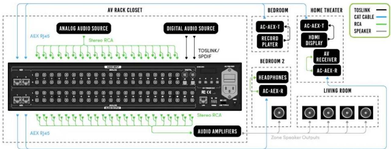
The AC-MAX-24 is a 24 I/O 2U rack-mountable audio matrix featuring dual RCA, TOSLINK, and Digital Coaxial ports, as well as 2 AEX inputs and 2 AEX outputs, allowing users to return audio from decentralized sources (such as a vinyl player) or extend audio out to a remote zone (such as a guest house or room with a local soundbar).
The diagram below shows the basic application of the AC-MAX-24. The audio path can either come from the audio sources directly or from remote audio sources via the AC-AEX-KIT as shown below.
flowchart
graph TD
    A["AV RACK CLOSET"] --> B["ANALOG AUDIO SOURCE"]
    A --> C["DIGITAL AUDIO SOURCE"]
    B --> D["AEX RJ45"]
    C --> E["TOSLINK/SPDIF"]
    D --> F["AC-AEX-T"]
    E --> G["RECORD PLAYER"]
    F --> H["AC-AEX-T"]
    G --> I["HDMI DISPLAY"]
    H --> J["AC-AEX-R"]
    I --> K["AV RECEIVER"]
    J --> L["LIVING ROOM"]
    K --> M["AC-AEX-R"]
    L --> N["AC-AEX-T"]
    M --> O["AC-AEX-T"]
    N --> P["AC-AEX-T"]
    O --> Q["AC-AEX-T"]
    P --> R["AC-AEX-T"]
    Q --> S["AC-AEX-T"]
    R --> T["AC-AEX-T"]
    S --> U["AC-AEX-T"]
    T --> V["AC-AEX-T"]
    U --> W["AC-AEX-T"]
    V --> X["AC-AEX-T"]
    W --> Y["AC-AEX-T"]
    X --> Z["AC-AEX-T"]
    Y --> AA["AC-AEX-T"]
    Z --> AB["AC-AEX-T"]
    AA --> AC["AC-AEX-T"]
    AB --> AD["AC-AEX-T"]
    AC --> AE["AC-AEX-T"]
    AD --> AF["AC-AEX-T"]
    AE --> AG["AC-AEX-T"]
    AF --> AH["AC-AEX-T"]
    AG --> AI["AC-AEX-T"]
    AH --> AJ["AC-AEX-T"]
    AI --> AK["AC-AEX-T"]
    AJ --> AL["AC-AEX-T"]
    AK --> AM["AC-AEX-T"]
    AL --> AN["AC-AEX-T"]
    AM --> AO["AC-AEX-T"]
    AN --> AP["AC-AEX-T"]
    AO --> AQ["AC-AEX-T"]
    AP --> AR["AC-AEX-T"]
    AQ --> AS["AC-AEX-T"]
    AR --> AT["AC-AEX-T"]
    AS --> AU["AC-AEX-T"]
    AT --> AV["AC-AEX-T"]
    AU --> AW["AC-AEX-T"]
    AV --> AX["AC-AEX-T"]
    AW --> AY["AC-AEX-T"]
    AX --> AZ["AC-AEX-T"]
    AY --> BA["AC-AEX-T"]
    AZ --> BB["AC-AEX-T"]
Compatible Devices
AC-AEX-KIT (sold separately)
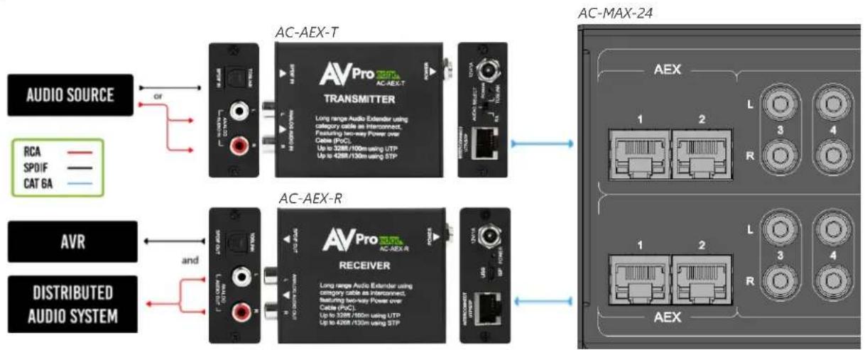
The AVPro Edge AC-AEX-KIT is a pair of PoC (Power over Cable) powered transmitter (AC-AEX-T) and receiver (AC-AEX-R) modules that extend 2-channel analog and digital audio signals over standard category cable via AVPro Edge's exclusive AEX technology. The AC-AEX-KIT is ideal for sending and receiving audio signals to/from decentralized devices to/from a centrally located audio distribution system such as the AC-MAX-24.
flowchart
graph LR
    A["AUDIO SOURCE"] -->|OR| B["AC-AEX-T TRANSMITTER"]
    C["RCA"] --> B
    D["SPDIF"] --> B
    E["CAT 6A"] --> B
    F["AVR"] --> G["AC-AEX-R RECEIVER"]
    H["DISTRIBUTED AUDIO SYSTEM"] --> G
    B --> I["AC-MAX-24"]
    G --> I
    style A fill:#f9f,stroke:#333
    style C fill:#f9f,stroke:#333
    style H fill:#f9f,stroke:#333
    style B fill:#ccf,stroke:#333
    style G fill:#ccf,stroke:#333
    style I fill:#cfc,stroke:#333

IMPORTANT:
Each AEX port on the AC-MAX-24 must be paired with an AC-AEX-T or AC-AEX-R for complete operation.
PRODUCT OVERVIEW
Box Contents
(1x) AC-MAX-24 Stereo Audio Matrix
(2x) 2U Rack Mounting Brackets (pre-attached)
(1x) 3-Pin Terminal Block Connector
(4x) Mounting Feet
(4x) Mounting Feet Screws
(1x) Ground Wire
(1x) AC Power Cord
Technical Specifications
| Audio | |
| Frequency Response | 20-20 kHz |
| Analog Input Voltage | 0.8 VRMS, 2.3 Vp-p |
| Analog Output Voltage | 1.5 VRMS, 4.4 Vp-p |
| Digital | 2 Channel PCM |
| Supported Sample Rates (kHz) | 32, 44.1, 48, 88.2, 96, 176, 192 |
| Latency | ≤60 milliseconds |
| Mute | Available on all outputs |
| Audio Inputs | |
| AEX Audio | 2 |
| RCA | 20 |
| Digital TOSLINK | 2 |
| Digital Coaxial | 2 |
| Audio Outputs | |
| AEX Audio | 2 |
| RCA | 22 |
| Control | |
| Interfaces | RS-232, IP/LAN |
| Additional Connections | |
| In-System Programming | USB Type C |
| 12V DC Trigger Output | 4 |
| Power | |
| Total Power Consumption | 50 Watts Maximum |
| AC Power | 100-240 VAC |
| Dimensions | |
| Height x Width x Depth(Standalone Unit) | Millimeters: 88 x 440 x 234.95Inches: 3.5 x 17.5 x 9.25 |
| Height x Width x Depth(Packaged Unit) | Millimeters: 172 x 578 x 375Inches: 6.75 x 22.75 x 15 |
| Weight(Standalone Unit) | 8.7 lbs (3.95 kg) |
| Weight(Packaged Unit) | 11.9 lbs (5.4 kg) |
| Rack Space | 2U |
| *Specifications are subject to change without notice. Mass and dimensions are approximate. | |
Front and Rear Panel Overview
Front Panel

Rear Panel
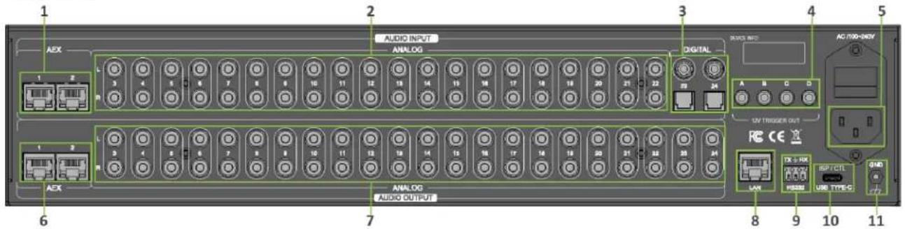
1 AEX INPUTS (1-2)
• (2x) 8-pin RJ-45 female connector
• Long-range audio extension input ports for connecting AC-AEX-KIT
• Power over Cable (PoC)
- Unshielded Twisted Pair (UTP): up to 100 meters (328 ft)
• Shielded Twisted Pair (STP): up to 130 meters (426 ft)
2 ANALOG AUDIO INPUTS (3-22)
• (20x) Stereo RCA line-level analog audio input ports
3 DIGITAL AUDIO INPUTS (23-24)
• (2x) Digital Coaxial audio input ports
4 12V TRIGGER OUT
• (2x) Digital Optical (TOSLINK) audio input ports
5 AC POWER INLET
• (4x) 3.5mm output ports
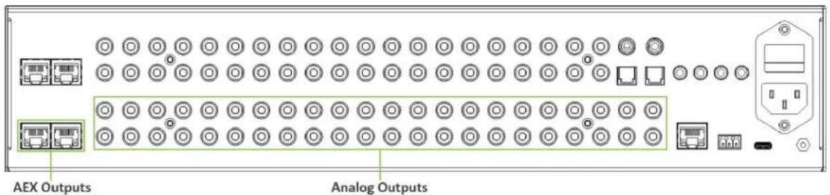
6 AEX OUTPUTS (1-2)
• Main AC power for the AC-MAX-24
• (2x) 8-pin RJ-45 female connector
• Long-range audio extension input ports for connecting AC-AEX-KIT
• Power over Cable (PoC)
- Unshielded Twisted Pair (UTP): up to 100 meters (328 ft)
• Shielded Twisted Pair (STP) up to 130 meters (426 ft)
7 ANALOG AUDIO OUTPUTS (3-24)
• (22x) Stereo RCA analog audio output ports
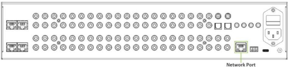
8 LAN
• 8-pin RJ-45 female connector
- Connect to the LAN, router, or third-party control system
| 9 | RS232 CONTROL | • 3-pin terminal block connector port |
| 10 | ISP / CTL USB TYPE-C | • Proprietary service port for AVPro Edge technical assistance |
| 11 | GND | • Ground screw• Connect with the provided ground wire to the conducting parts |
INSTALLATION
Rack Mounts
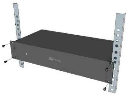
The AC-MAX-24 can be mounted in a 2U rack-style enclosure and is compatible with all standard 19-inch rack mounts. The (2x) mounting brackets are pre-assembled to the unit for quick installation.
1 Align the holes on the mounting brackets with the holes on both sides of the rack.
2 Attach the mounting brackets to the rack with rack screws (not included).
natural_image
3D rendering of a black rectangular electronic device with metal plates and mounting holes (no text or symbols visible)Mounting Feet Assembly
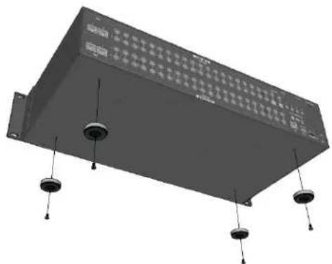
The (4x) mounting feet can be assembled to the unit with the (4x) provided mounting screws.
1 Align the holes on the mounting feet with the holes underneath the unit.
2 Attach the mounting feet to the unit with the provided screws.
natural_image
3D rendering of a rectangular electronic device with four hanging pins and a grid-like top panel (no visible text or symbols)Grounding Cable
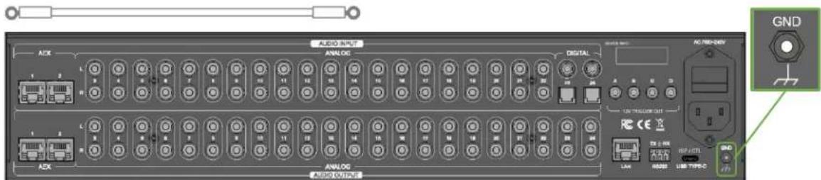
Use a screwdriver to attach the yellow ground cable to the pre-installed screw on the back of the unit, then attach the other end to a suitable grounded object.
WIRING AND CONNECTIONS
Audio Connections
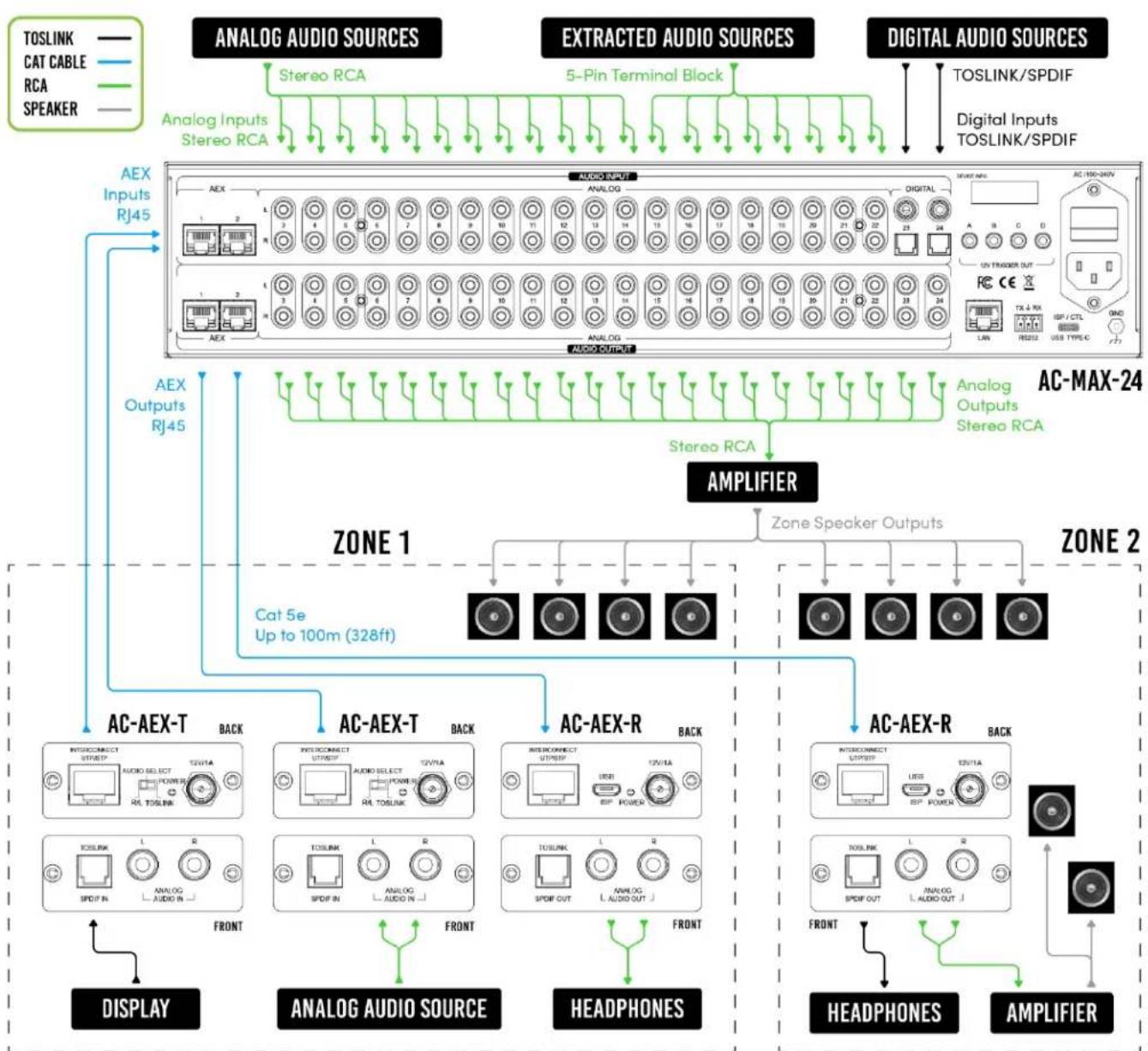
AVPro Edge recommends using shielded RCA interconnected cabling between the AC-MAX-24 and connected analog devices to maintain a high level of audio performance.
The diagram below shows the audio connections of the AC-MAX-24:
flowchart
graph TD
    A["ANALOG AUDIO SOURCES"] --> B["Analog Inputs Stereo RCA"]
    C["EXTRACTED AUDIO SOURCES"] --> D["5-Pin Terminal Block"]
    E["DIGITAL AUDIO SOURCES"] --> F["TOSLINK/SPDIF"]
    E --> G["Digital Inputs TOSLINK/SPDIF"]
    H["AEX Inputs RJ45"] --> I["AEX Outputs RJ45"]
    I --> J["AC-AEX-T BACK"]
    I --> K["AC-AEX-T BACK"]
    I --> L["AC-AEX-R BACK"]
    I --> M["AC-AEX-R BACK"]
    N["DISPLAY"] --> O["ANALOG AUDIO SOURCE"]
    N --> P["HEADPHONES"]
    Q["AMPLIFIER"] --> R["AC-MAX-24"]
    S["TOSLINK"] --> T["AC-100-040N"]
    U["LAN"] --> V["RS222 USB TYPE-C"]
    W["AC-AEX-T"] --> X["INTERCONNECT OUTPUT"]
    Y["AC-AEX-T"] --> Z["INTERCONNECT OUTPUT"]
    AA["AC-AEX-T"] --> AB["INTERCONNECT OUTPUT"]
    AC["AC-AEX-T"] --> AD["INTERCONNECT OUTPUT"]
    AE["AC-AEX-T"] --> AF["INTERCONNECT OUTPUT"]
    AG["AC-AEX-T"] --> AH["INTERCONNECT OUTPUT"]
    AI["AC-AEX-T"] --> AJ["INTERCONNECT OUTPUT"]
    AK["AC-AEX-T"] --> AL["INTERCONNECT OUTPUT"]
    AM["AC-AEX-T"] --> AN["INTERCONNECT OUTPUT"]
    AO["AC-AEX-T"] --> AP["INTERCONNECT OUTPUT"]
    AQ["AC-AEX-T"] --> AR["INTERCONNECT OUTPUT"]
    AS["AC-AEX-T"] --> AT["INTERCONNECT OUTPUT"]
    AU["AC-AEX-T"] --> AV["INTERCONNECT OUTPUT"]
    AW["AC-AEX-T"] --> AX["INTERCONNECT OUTPUT"]
    AY["AC-AEX-T"] --> AZ["INTERCONNECT OUTPUT"]
    BA["AC-AEX-T"] --> BB["INTERCONNECT OUTPUT"]
    BC["AC-AEX-T"] --> BD["INTERCONNECT OUTPUT"]
    BE["AC-AEX-T"] --> BF["INTERCONNECT OUTPUT"]
    BG["AC-AEX-T"] --> BH["INTERCONNECT OUTPUT"]
    BI["AC-AEX-T"] --> BJ["INTERCONNECT OUTPUT"]
    BK["AC-AEX-T"] --> BL["INTERCONNECT OUTPUT"]
    BM["AC-AEX-T"] --> BN["INTERCONNECT OUTPUT"]
    BO["AC-AEX-T"] --> BP["INTERCONNECT OUTPUT"]
    BQ["AC-AEX-T"] --> BR["INTERCONNECT OUTPUT"]
    BS["AC-AEX-T"] --> BT["INTERCONNECT OUTPUT"]
    BU["AC-AEX-T"] --> BV["INTERCONNECT OUTPUT"]
    BW["AC-AEX-T"] --> BX["INTERCONNECT OUTPUT"]
    BY["AC-AEX-T"] --> BYB["INTERCONNECT OUTPUT"]
    CA["AC-AEX-T"] --> CB["INTERCONNECT OUTPUT"]
    CC["AC-AEX-T"] --> CD["INTERCONNECT OUTPUT"]
    BEX --> CE["TOSLINK"]
    BEX --> CF["TOSLINK"]
    BEX --> GD["TOSLINK"]
    BEX --> DH["TOSLINK"]
    BEX --> DI["TOSLINK"]
    BEX --> DJ["TOSLINK"]
RS-232 Control
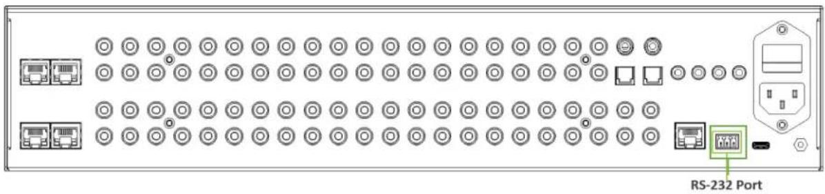
The RS-232 control port located in the bottom right corner on the rear panel is used to communicate with the AC-MAX-24 via a computer or third-party control system.
natural_image
Front panel of a network device showing rows of ports, connectors, and an RS-232 port (no text or symbols on components)Wiring for this port uses a 3-pin terminal block connector to DB9, where only pins 2, 3, and 5 are used. If the control devices do not have a DB9 port, a USB to DB9 adapter may be required.

For RS-232 control, use a null modem serial cable adapter and set the serial communications to: Baud: 57600, no parity, 8 data bits, and 1 stop bit, with no handshaking.
Add a carriage return (Enter key) after each command when using direct commands. The unified command list (ASCII) can be located here.
LAN Wiring
The IP control port located in the bottom right corner on the rear panel is used to communicate with the AC-MAX-24 via a LAN, router, or third-party control system processor. For TCP/IP control, commands use Telnet Port 23.
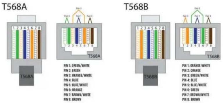
The recommended termination is based on TIA/EIA T568A or T568B standards for the wiring of the twisted pair cables:
INITIAL SETUP
Make the physical connections to the input and output devices using the following steps below. For initial setup, it is recommended to connect the AC-MAX-24 to a LAN (Local Area Network) using a control PC on the same network once all the physical connections are made, followed by accessing the Web UI and checking for any firmware updates to the unit.
Connecting the Devices
1 Connect the audio source devices to the audio inputs on the back of the unit.
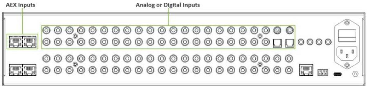
2 Connect the audio output devices to the audio outputs on the back of the unit.
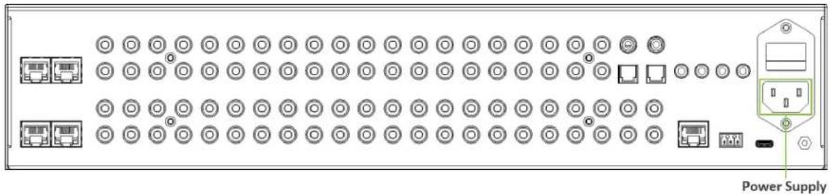
3 Connect the provided power cable to the AC inlet on the back of the unit, then plug the power cable into a standard wall receptacle.
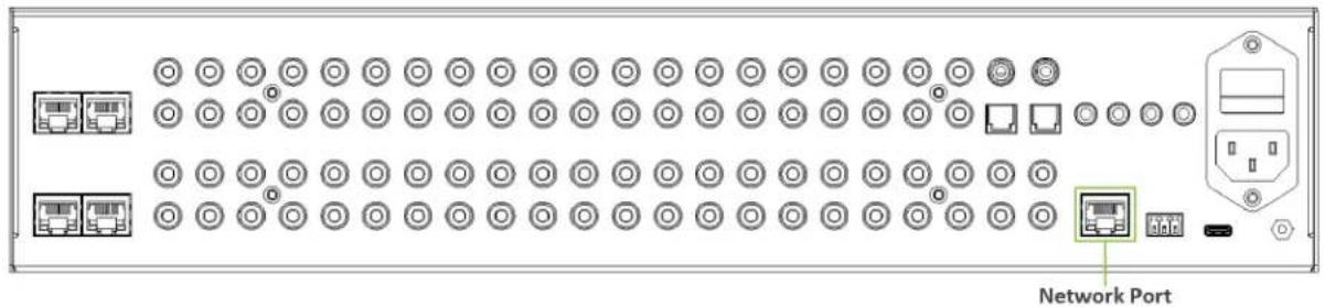
4 Connect the NETWORK port on the back of the unit to a LAN, router, or third-party control system.
Locating the IP Address
The default IP setting is DHCP mode, an IP address will be automatically assigned to the unit by the DHCP server. Use a PC on the same network to locate the unit's IP address, then enter it into a web browser (such as Chrome or Edge) to access the unit's Web UI. Once connected, you can use the Web UI to assign the unit a static IP address. If there is no DHCP server on the network, the unit's IP address can also be located by connecting to the RS-232 port on the back of the unit and sending serial commands using the API. For more information, see the RS-232 Control page.
Accessing the Web UI
The AC-MAX-24 features the built-in AVPro Edge User Interface (AEUI) that can be accessed through a web browser for configuration and control. For initial setup, it is recommended to connect the AC-MAX-24 to a local area network (LAN) with a computer on the same network to access the built-in Web UI and check for any firmware updates to the unit.
OTA Cloud Services
Firmware updates to the unit can be performed OTA (Over-the-Air) by enabling the Cloud Services setting on the Web UI. This allows the unit to search the Cloud for the latest versions of firmware. If a newer version of firmware is detected, a dialog box will prompt the new update is available from the Web UI.
1 Enter in the unit's IP address into a Chrome or Edge web browser to access the unit's Web UI.

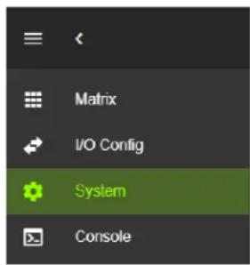
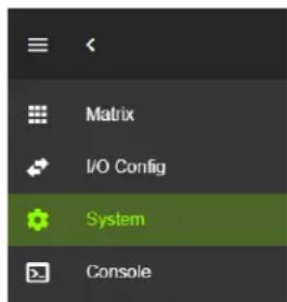
2 Navigate to the System tab page.
3 In the Cloud Services section, review the Privacy Policy and Terms of Use, then check both boxes and select the Enable Cloud Services toggle setting.
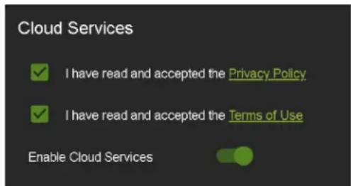

IMPORTANT:
This is a required step in order for the unit to perform OTA firmware updates.
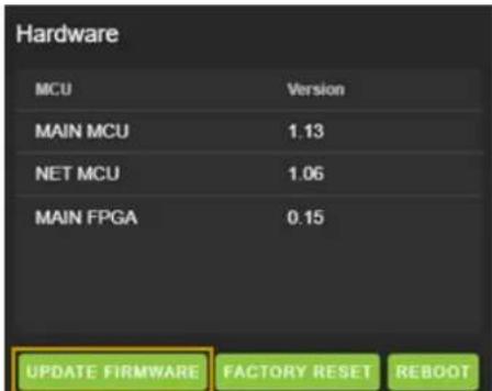
4 In the Hardware section, select the Update Firmware button. A new dialog box will open.
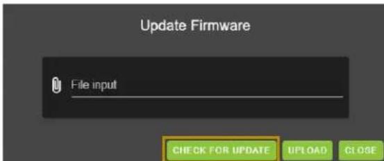
5 In the Update Firmware dialog box, select Check for Update. The unit will now check the Cloud for available firmware updates.
6 If the unit is already installed with the latest version of firmware, a notification window will prompt the message "No update available!" at the top of the page. Select the Close button.

7 If a newer version of firmware is detected from the Cloud, a notification window will prompt the message "New firmware update is available!". Select the Update button.

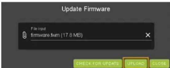
8 The unit's new firmware file will automatically populate into the File input field from the Cloud. Select the Upload button.
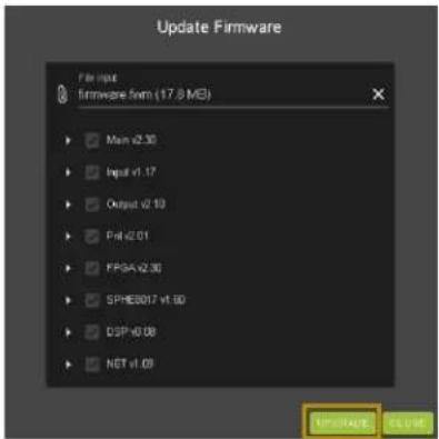
9 From this screen, newer versions of firmware can be viewed before they are installed. Select the Upgrade button. The unit will now begin installing the latest versions of firmware. DO NOT refresh the webpage or power off the unit during the update.
10 Once the progress bar reaches 100%, select the Close button and refresh the webpage.
11 The unit will automatically reboot once the firmware updates are complete. After the unit reboots, refresh the webpage to verify that the firmware update was successful.
NAVIGATING THE WEB UI
The AC-MAX-24 features the built-in AVPro Edge User Interface (AEUI) that can be accessed through a web browser for configuration and control. Different tools and settings can be selected from the tab pages located on the navigation menu column on the left side of the screen.
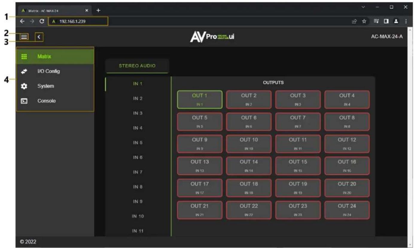
1 Enter the unit's IP address into a web browser, such as Chrome or Edge, to access the Web UI.
2 To hide the navigation menu, select the hamburger menu icon ☐.
3 To hide the navigation menu text and show only the menu icons, select the left arrow icon
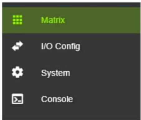
4 To navigate through the different pages, select the individual tab pages from the navigation menu. This will highlight the tab page in green to indicate the currently selected page.
Matrix
The Matrix page layout consists of the Stereo Audio Inputs column on the left and the Outputs grid on the right. Each Input and Output can be individually selected to route the input's audio signals to the output(s).
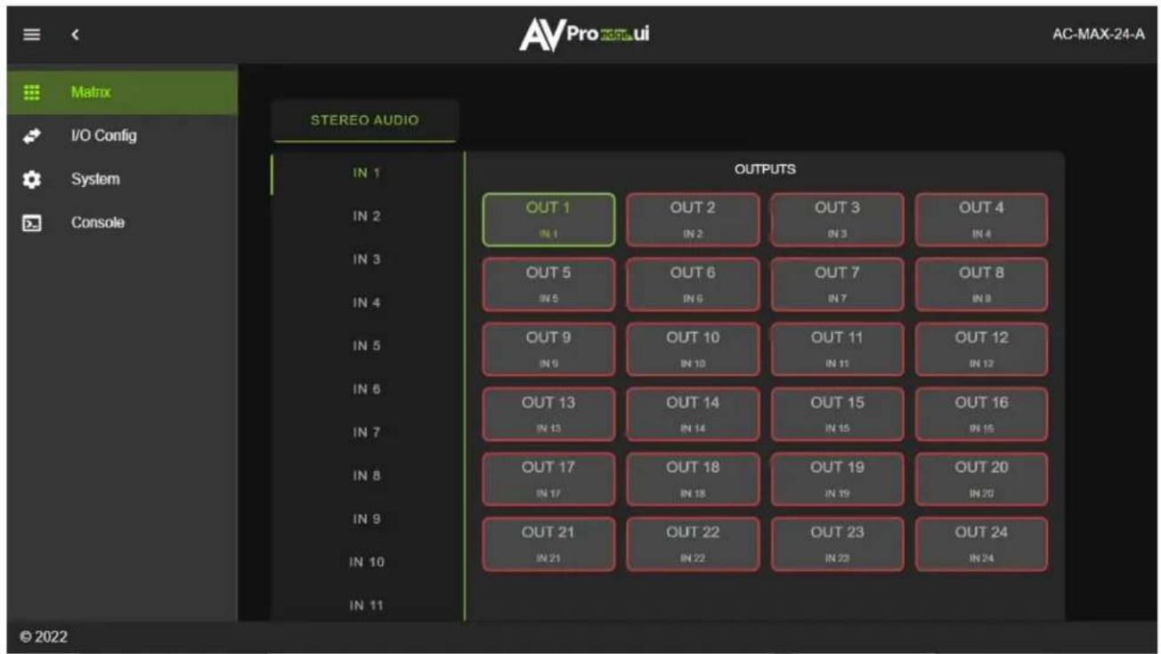
Matrix Switching
1 From the Inputs column, select the desired input. This will highlight the input with a green text to indicate the selection was made.
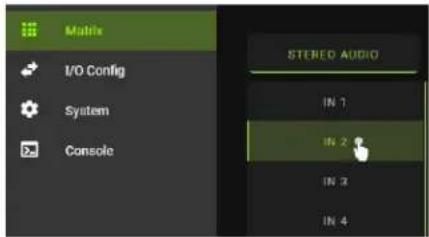
2 From the Outputs grid, select the desired output(s) to route the selected input to. This will highlight the output(s) with a green border to indicate the selection was made.
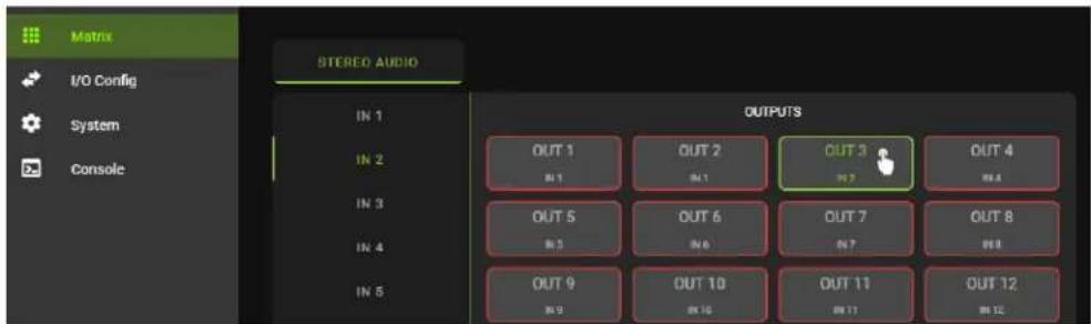
3 The selected input's audio signals are now routed to the selected output(s).
I/O Config
The I/O Config tab page features tools and settings for configuring the audio inputs and outputs.
Stereo Audio Input Settings
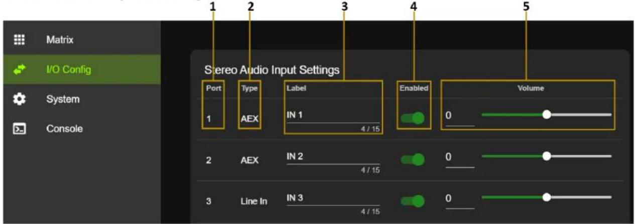
| 1 | Port | Shows the audio input port number. |
| 2 | Type | Shows the audio input connection type. |
| 3 | Label | Select the text field to enter in a custom name for the input. (Limit of 15 characters) |
| 4 | Enabled | Select the toggle switch to enable or disable the audio input. |
| 5 | Volume | Adjust the volume by using the slider bar or entering a value (0~100) in the text field. |
Stereo Audio Output Settings
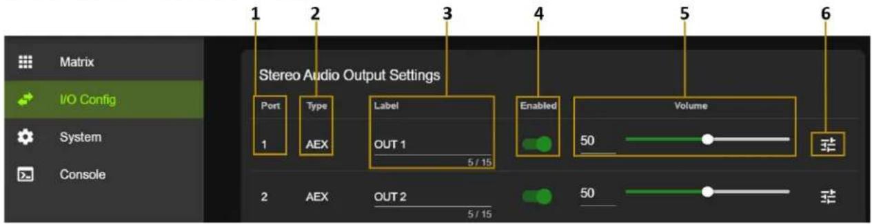
| 1 | Port | Shows the audio output port number. |
| 2 | Type | Shows the audio output connection type. |
| 3 | Label | Select the text field to enter in a custom name for the output. (Limit of 15 characters) |
| 4 | Enabled | Select the toggle switch to enable or disable the audio output. |
| 5 | Volume | Adjust the volume by using the slider bar or entering a value (0~100) in the text field. |
| 7 | EQ | Select to view the output's Audio Configuration settings. |
Audio Configuration
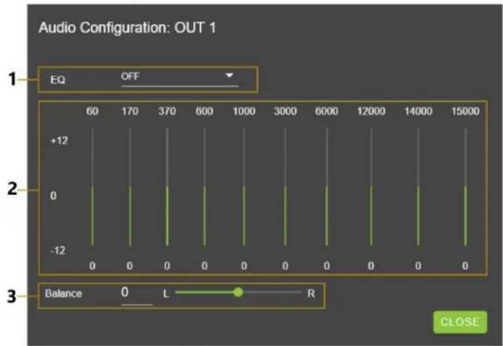
| 1 EQ | Dropdown menu containing a list of several preset equalizer settings that can be applied to change the frequency response of the audio output. |
| 2 Frequency | Graphic equalizer showing the individual frequency bands of the output's audio. |
| NOTE: This graphic equalizer is only intended to be used as a visual reference of the individual audio frequency gains. Manual adjustments cannot be made to it. | |
| 3 Balance | Adjust the Left and Right volume by using the slider bar or entering a value (-10 to +10) in the text field. |
| NOTE: -10 is balanced left, 0 is balanced, and +10 is balanced right. |
Equalizer
The AC-MAX-24 includes a digital 5-band parametric equalizer (EQ) with 29 presets and 24 user EQ profiles to enhance listener experience. EQ's 1-27 consist of various combinations of bass, midrange, and treble attenuations in increments of 6dB up to a total of 12dB. The table below shows the gain values for the various EQ presets. EQ's 28 and 29 are high and low pass filters, respectively. The remaining EQ's ranging from 30-53 are user configurable, where the center frequency, gain, Q-factor can be set for each of the 5 bands via RS-232 or Web UI Console. Further details can be found in the Equalizer Commands in the command list.
| EQ | Bass | Mid | Treble | EQ | Bass | Mid | Treble | EQ | Bass | Mid | Treble |
| 1 | 0 | 0 | 0 | 10 | -6 | 0 | 0 | 19 | -12 | 0 | 0 |
| 2 | 0 | 0 | -6 | 11 | -6 | 0 | -6 | 20 | -12 | 0 | -6 |
| 3 | 0 | 0 | -12 | 12 | -6 | 0 | -12 | 21 | -12 | 0 | -12 |
| 4 | 0 | -6 | 0 | 13 | -6 | -6 | 0 | 22 | -12 | -6 | 0 |
| 5 | 0 | -6 | -6 | 14 | -6 | -6 | -6 | 23 | -12 | -6 | -6 |
| 6 | 0 | -6 | -12 | 15 | -6 | -6 | -12 | 24 | -12 | -6 | -12 |
| 7 | 0 | -12 | 0 | 16 | -6 | -12 | 0 | 25 | -12 | -12 | 0 |
| 8 | 0 | -12 | -6 | 17 | -6 | -12 | -6 | 26 | -12 | -12 | -6 |
| 9 | 0 | -12 | -12 | 18 | -6 | -12 | -12 | 27 | -12 | -12 | -12 |
Trigger Output Settings
The AC-MAX-24 is equipped with four 12V trigger ports that can be configured to automatically turn on/off an amplifier or AV receiver. The trigger port will continuously output 12 VDC when enabled and an audio signal is detected at any assigned audio output. When active, the trigger port will continue to output 12 VDC until no audio is detected at all assigned audio outputs for a minimum duration of the set Timeout period or when the trigger is disabled.

NOTE:
An audio output and its routed input must both be enabled in order to detect audio at the output.
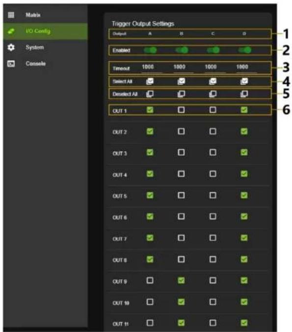
| 1 | Trigger Output | Shows the trigger output port letter. |
| 2 | Enabled | Select the toggle switch to enable or disable the trigger output port. |
| 3 | Timeout | Select the text field to enter the trigger Timeout duration in milliseconds.(Limit of 5 characters) |
| 4 | Select All | Select the check box to assign all audio outputs to this column's trigger output port. |
| 5 | Deselect All | Select the check box to unassign all audio outputs from this column's trigger output port. |
| 6 | Audio Output | Check box to assign or unassign this row's audio output to this column's trigger output port. |
System
IP Settings
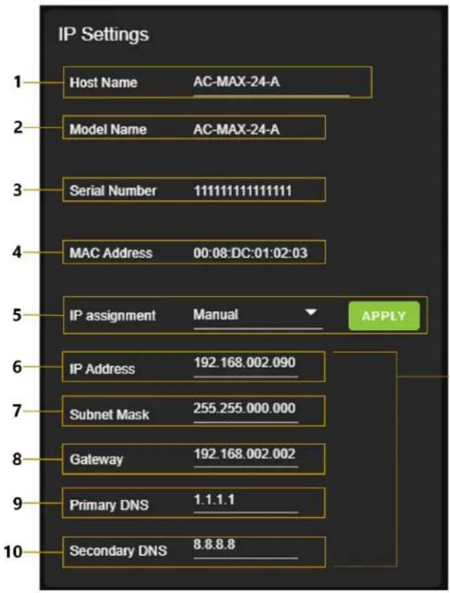
These will be assigned by a DHCP reservation from the router when the IP Assignment is set to Automatic, or they can be manually entered in when the IP Assignment is set to Manual.
Select the Apply button when manually entering in the IP Assignment, IP Address, Subnet Mask, Gateway, Primary DNS, and Secondary DNS for changes to take effect.
| 1 | Host Name | Select the text field to enter in a custom name for the unit. The default shows the unit's model number. |
| 2 | Model Name | Shows the unit's AVPro Edge model number. |
| 3 | Serial Number | Shows the unit's unique serial number. |
| 4 | MAC Address | Shows the unit's unique MAC address. |
| 5 | IP Assignment | Select the dropdown menu to set the unit's IP mode to DHCP (default) or Manual (Static IP), then select the Apply button. |
| 6 | IP Address | Shows the unit's IP address. |
| 7 | Subnet Mask | Shows the unit's subnet mask. |
| 8 | Gateway | Shows the unit's default gateway. |
| 9 | Primary DNS | Shows the unit's primary domain name server. |
| 10 | Secondary DNS | Shows the unit's secondary domain name server. |
IP Control
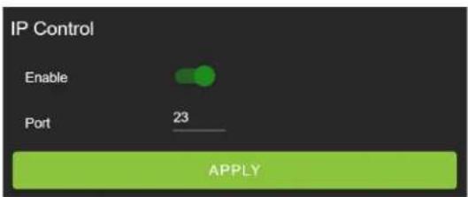
| 2 | Enable | Select the toggle switch to enable or disable IP/TCP control. |
| 3 | Port | Select the text field to set the Telnet port. Default is Telnet port 23. |
Admin Web Interface
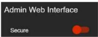
Select the Secure toggle switch to enable (green) or disable (red). When enabled, the username and password can be changed.
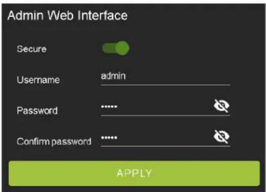
With the Admin Web Interface enabled, the only menu that will be accessible on the Web UI will be the Matrix tab page. The rest of the settings will require the Admin login.
Default username: admin
Default password: admin
User Web Interface
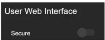
Select the Secure toggle switch to enable (green) or disable (grey). When enabled, the username and password can be changed.

NOTE:
The Admin Web Interface must first be enabled before this setting can be changed.
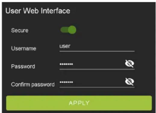
With the Admin and User Web Interfaces enabled, no menus will be accessible on the Web UI without first logging in.
Logging in with the User credentials, the only menu that will be accessible on the Web UI will be the Matrix tab page. The rest of the settings will require the Admin login.
Default username: user
Default password: user123
Hardware
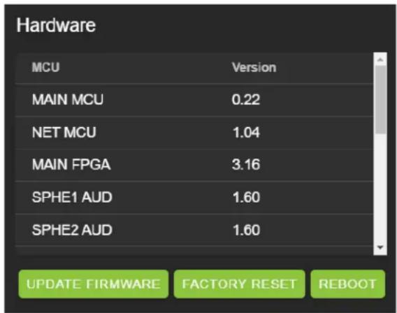
This section shows the unit's current firmware versions and provides options for updating firmware, factory resetting the unit, and rebooting the unit.
Cloud Services
Cloud Services allows OTA (Over-the-Air) firmware updates to be performed onto the unit. This allows the unit to search the Cloud for the latest versions of firmware, as well as enable third-party remote management services. If the Cloud Services setting is disabled, the unit will opt out of any previously enabled services and will not be able to access OTA firmware updates.

NOTE:
When updating firmware, some settings and configurations may revert back to their original factory default settings and may need to be re-applied after the firmware updates are complete. It is always recommended to backup and save your settings and configurations before updating firmware.
1 Enter in the unit's IP address into a Chrome or Edge web browser to access the unit's Web UI.

2 Navigate to the System tab page.
3 In the Cloud Services section, review the Privacy Policy and Terms of Use, then check both boxes and select the Enable Cloud Services toggle setting.
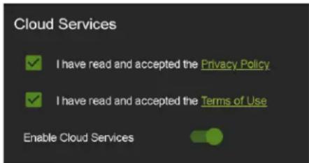

IMPORTANT: This is a required step in order for the unit to perform OTA firmware updates.
4 In the Hardware section, select the Update Firmware button. A new dialog box will open.
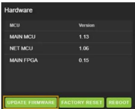
5 In the Update Firmware dialog box, select Check for Update. The unit will now check the Cloud for available firmware updates.
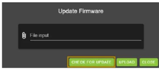
6 If the unit is already installed with the latest version of firmware, a notification window will prompt the message "No update available!" at the top of the page. Select the Close button.

7 If a newer version of firmware is detected from the Cloud, a notification window will prompt the message "New firmware update is available!". Select the Update button.

8 The unit's new firmware file will automatically populate into the File input field from the Cloud. Select the Upload button.
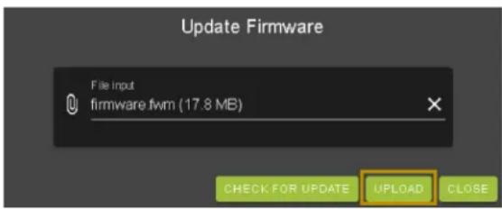
9 From this screen, newer versions of firmware can be viewed before they are installed. Select the Upgrade button. The unit will now begin installing the latest versions of firmware. DO NOT refresh the webpage or power off the unit during the update.
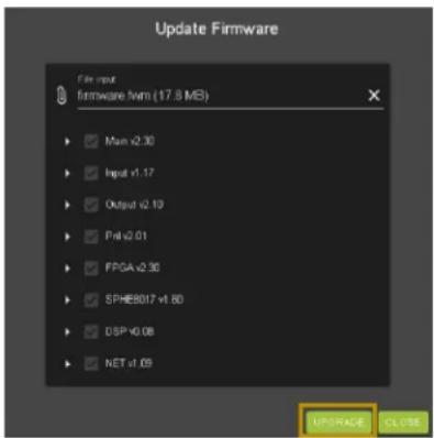
10 Once the progress bar reaches 100%, select the Close button. The unit will automatically reboot once the firmware updates are complete. After the unit reboots, refresh the webpage.
Console
The Web UI features a built-in command console that allows API commands to be sent directly to the unit.
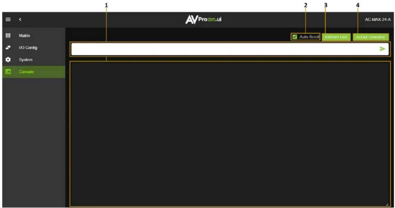
| 1 | Text Field | Enter the unit's API commands into this field. System events generated by the unit will record in a continuous stream while the Console tab page is open within the Web UI. |
| 2 | Auto-Scroll | Check box that enables or disables auto-scrolling as system events are generated. |
| 3 | Export Log | Select to download a .txt file of the information recorded by the console log. The console log only records information while the unit's Web UI is opened to the Console tab page and does not record or store information internally. |
| 4 | Clear Console | Select to clear the information recorded in the console log. |
Command List
| Command | Action |
| H | Help |
| STA | Show global system status |
| SET RST | Reset to factory defaults |
| SET RBT | System reset to reboot |
| SET LAN RBT | Set LAN MCU reset to reboot |
| SET ADDR xx | Set System Address to xx {xx=[00-99](00=single)} |
| SET BAUDR x | Set System Baudrate to x {x=[0~5](0=9600, 1=14400, 2=19200, 3=38400, 4=57600, 5=115200)} |
| GET ADDR | Get System Address |
| GET STA | Get System Status |
| GET CONFIG | Get System Configuration |
| GET BAUDR | Get System Baudrate |
| Input Setup Commands | |
| SET INx EN/DIS | Set Audio Input Enable/Disable {x=[0-24](0=all)} |
| SET INx VOLy | Set Audio Input Volume Adjustment {x=[0-24](0=all), y=-50~+50} |
| GET INx EN | Get Audio Input Enable/Disable {x=[0~24](0=all)} |
| GET INx VOL | Get Audio Input Volume Adjustment {x=[0~24](0=all)} |
| GET INx SIG STA | Get Input x Signal Status {x=[0-24](0=All)}0 = Left no audio, Right no audio1 = Left has audio, Right no audio2 = Left no audio, Right has audio3 = Left has audio, Right has audio |
| Output Setup Commands | |
| SET OUTx EN/DIS | Set Audio Output Enable/Disable {x=[0~24](0=all)} |
| SET OUTx AS IN y | Set Audio Output x to Input y {x=[0~24](0=all), y=[1~24]} |
| SET OUTx FOLLOW y OUTz | Set Audio Output x follow settings {x=[0~24](0=all[excluding self])}Follow Modes 0=None, 1=Source, 2=Volume, 3=Source+VolumeIf Follow Mode ! 0, then OUTz is the output that will be followed |
| SET OUTx MUTE/UNMUTE | Set Audio Output Mute/Unmute {x=[1~24](0=all)} |
| SET OUTx VOL y | Set Output x Volume Level y {x=[0~24](0=All),y=[0~100]} |
| SET OUTx VOL + y | Increase Output x Volume by y {x=[1~24], y=[1~100, optional default 1]} |
| SET OUTx VOL - y | Decrease Output x Volume by y {x=[1~24], y=[1~100, optional default 1]} |
| SET OUTx VOL LOCK/UNLOCK | Lock / Unlock Output x Volume {x=[0~24](0=ALL)} |
| SET OUTx BAL y | Set Output x Balance y {x=[0~24](0=All),y=[0~40, Left = 0, Right = 40, Balanced = 20]} |
| SET OUTx BAL + y | Increase Output x Balance by y {x=[1~24], y=[1~40, optional default 1]} |
| SET OUTx BAL - y | Decrease Output x Balance by y {x=[1~24], y=[1~40, optional default 1]} |
| GET OUTx EN | Get Audio Output Enable/Disable Status {x=[0~24](0=all)} |
| GET OUTx AS | Get Output x Audio Route {x=[0~24](0=all)} |
| GET OUTx FOLLOW | Get Audio Output x follow settings {x=[0~24](0=all[excluding self])}Follow Modes 0=None, 1=Source, 2=Volume, 3=Source+VolumeIf Follow Mode ! 0, then OUTz is the output that will be followed |
| GET OUTx MUTE | Get Audio Output Mute/Unmute {x=[0~24](0=all)} |
| GET OUTx VOL | Get Output x Volume Level {x=[0~24](0=All)} |
| GET OUTx VOL LOCK | Get Output x Volume Lock Status {x=[0~24](0=ALL)} |
| GET OUTx BAL | Set Output x Balance {x=[0~24](0=All),y=[0~40, Left = 0, Right = 40, Balanced = 20]} |
| Equalizer Commands | |
| SET OUTx EQ y | Set Output x to EQ y {x=[0-24](0=All),y=[0~53](0=OFF)} |
| SET EQx BANDy Ff Gg Qq | Set EQ Mode x Band Frequency, Gain, and Q values{x=30~53, y=1~5, f=1~24000, g=-12.0~12.0, q=0.1~10.0} |
| GET OUTx EQ | Get Output x EQ {x=[0-24](0=All)} |
| GET EQy BANDy | Get EQ Mode x Band Frequency, Gain, and Q values {x=30~53, y=0~5 (0=All)} |
Trigger Commands
| SET TRIGGER y EN/DIS | Set Trigger y Enabled/Disabled {y=[0=All,1-4]} |
| SET TRIGGER y OUTx ON/OFF | Set Trigger y Output x mapping ON/OFF {x=[0-24](0=ALL), y=[0=All,1-4]} |
| SET TRIGGER y TIMEOUT x | Set Trigger y disable timeout to x (ms) {x=[0-65535](0=Instant), y=[0=All,1-4]} |
| GET TRIGGER y EN | Get Trigger y Enabled/Disabled {y=[0=All,1-4]} |
| GET TRIGGER y OUTx | Get Trigger y Output x mapping ON/OFF {x=[0-24](0=ALL), y=[0=All,1-4]} |
| GET TRIGGER y TIMEOUT | Get Trigger y disable timeout in ms {y=[0=All,1-4]} |
Network Setup Commands
| SET RIP xxx.xxx.xxx.xxx | Set Route IP Address to xxx.xxx.xxx.xxx (xxx=[000~255]) |
| SET HIP xxx.xxx.xxx.xxx | Set Host IP Address to xxx.xxx.xxx.xxx (xxx=[000~255]) |
| SET NMK xxx.xxx.xxx.xxx | Set Net Mask to xxx.xxx.xxx.xxx (xxx=[000~255]) |
| SET TIP zzzz | Set TCP/IP Port to zzzz (zzzz=[0001~9999]) |
| SET DHCP y | Set DHCP {y=[0~1](0=Dis,1=Enable)} |
| GET RIP | Get Route IP Address |
| GET HIP | Get Host IP Address |
| GET NMK | Get Net Mask |
| GET TIP | Get TCP/IP Port |
| GET DHCP | Get DHCP Status |
| GET MAC | Get MAC Address |
TROUBLESHOOTING
- Verify Power -Check that the power supply is properly connected and on an active circuit.
- Verify Connections - Check that all cables are securely connected and properly terminated.
- Verify Current Versions - Check if are any firmware/software/driver updates available for the devices.
- No Sound - Verify the signal being sent is compatible with the connected devices in the signal chain. Ensure the device's volume level is properly adjusted and not set to mute. If a signal is present from the input source, the selected output(s) will have a visible red optical light that can be seen from the TOSLINK port.
- Static, Buzzing, or Humming Noises - Use shielded RCA cabling between the AC-MAX-24 and the connected analog devices to maintain a high level of audio performance. Ground the matrix to the conducting parts (equipment rack, mounting devices, truss systems, electrical switchboards, metal electrical conduits, etc.) This technique ensures all the equipment in an electrical system will use the same reference value for their signals and reduces the possibility of a ground loop, which can result in a shift in video signals and mains frequencies to exhibit a buzzing or humming noise in audio systems.
MAINTENANCE
To ensure reliable operation of this product as well as protecting the safety of any person using or
• handling this device while powered, please observe the following instructions.
- Use the power supplies provided. If an alternate supply is required, check voltage, polarity and that it has sufficient power to supply the device it is connected to.
- Do not operate these products outside the specified temperature and humidity range given in the above specifications.
- Ensure there is adequate ventilation to allow this product to operate efficiently.
- Repair of the equipment should only be carried out by qualified professionals as these products contain sensitive components that may be damaged by any mistreatment.
- Only use this product in a dry environment. Do not allow any liquids or harmful chemicals to come into contact with these products.
• Clean this unit with a soft, dry cloth. Never use alcohol, paint thinner or benzene to clean this unit.
DAMAGE REQUIRING SERVICE
The unit should be serviced by qualified service personnel if:
- The DC power supply cord or AC adapter has been damaged
- Objects or liquids have gotten into the unit
- The unit has been exposed to rain
• The unit does not operate normally or exhibits a marked change in performance
• The unit has been dropped or the housing damaged
SUPPORT
Should you experience any problems while using this product, first, refer to the Troubleshooting section of this manual before contacting Technical Support. When calling, the following information should be provided:
• Product name and model number
• Product serial number
• Details of the issue and any conditions under which the issue is occurring
- Clean this unit with a soft, dry cloth. Never use alcohol, paint thinner or benzene to clean this unit.
WARRANTY
The Basics
AVPro Edge warranties its products that are purchased from all Authorized AVPro Edge Resellers or direct purchases. Products are guaranteed to be free from manufacturing defects and of sound physical and electronic condition.
AVPro Edge has developed a warranty that anyone can get behind. We really wanted to take all the "red tape" out of a warranty and just make is simple. Our 10 YEAR NO BS warranty hinges on 3 elements.
• If you are having trouble, call us. We will attempt to troubleshoot your issue over the phone.
- If it's broken, we will replace it in advance on our dime and we'll also cover the return shipping. Repair is an option too, but it's YOUR call.
- We know you know what you are doing. We will not make you go through unnecessary steps to troubleshoot an extender...
Coverage Details
AVPro Edge will replace or repair (at customer choice) the defective product. If the product is out of stock or on backorder it can either be replaced with a comparable product of equal value/feature set (if available) or repaired.
Your warranty begins at receipt of product (as confirmed by shipping firm tracking). If tracking information is unavailable for any reason, the warranty will commence 30 ARO (After Receipt of Order). The coverage continues for 10 years.
Red Tape
AVPro Edge is not responsible for untraceable purchases or those that were made outside of an authorized channel.
If we conclude that a product or serial number has been tampered with as identified by warranty seal or physical examination the warranty will be void. Additionally, excessive physical damage (beyond normal wear & tear) the warranty may be voided or prorated based on the extent of the damage as examined by an AVPro Edge representative.
Damage caused by “acts of God” are not covered. They can include natural disasters, power surges, storms, earthquakes, tornadoes, sink holes, typhoons, tidal waves, hurricanes, or any other uncontrollable event related to nature.
Damage caused by incorrect installation will not be covered. Incorrect power supply, inadequate cooling, improper cabling, inadequate protection, static discharge are examples of this.
Products installed or sold by a third party to AVPro Edge will be serviced by the Authorized AVPro Edge Reseller. Accessories (IR Cables, RS-232, Power Supplies, etc.) are not included in the warranty. We will make acceptable efforts to source and supply replacements for defective accessories at a discounted rate as needed.
Obtaining an RMA
Dealers, Re-sellers, and Installers can request an RMA from AVPro Edge Tech Support Rep or their Sales Engineer.
You may also email support@avproedge.com or fill out the general contact form at avproedge.com/contact
End users may not request an RMA directly from AVPro Edge and will be referred back to the Dealer, Reseller, or Installer.
Shipping
For USA (not including Alaska and Hawaii). Shipping is covered on advanced replacements for FedEx Ground (some expressed exceptions may apply). Defective product return shipping is covered by AVPro Edge using an emailed return label. Items must be returned within 30 days of receipt of the replacement product, after 30 days, the customer will be billed. Other return shipping methods will not be covered.
For International (and Alaska and Hawaii) return shipping costs will be the responsibility of the returnee. Once the unit is scanned for return shipping AVPro Edge will ship the new unit for replacement.
Limitation on Liability
The maximum liability of AVPro Global Holdings LLC under this limited warranty shall not exceed the actual purchase price paid for the product. AVPro Global Holdings LLC is not responsible for direct, special, incidental, or consequential damages resulting from any breach of warranty or condition, or under any other legal theory to the maximum extent permitted by law. Taxes, Duties, VAT, and freight forwarding service charges are not covered or paid for by this warranty.
Obsolescence or incompatibility with newly invented technologies (after manufacture of product) is not covered by this warranty.
Obsolescence is defined as:
"Peripherals are rendered obsolete when current technology does not support product repair or re-manufacture. Obsolete products cannot be re-manufactured because advanced technologies supersede original product manufacturer capabilities. Because of performance, price and functionality issues, product redevelopment is not an option."
Discontinued or out of production items will be credited at fair market value towards a current product of equal or comparable capabilities and cost. Fair market value is determined by AVPro Edge.
Exclusive Remedy
To the maximum extent permitted by law, this limited warranty and the remedies set forth above are exclusive and in lieu of all other warranties, remedies, and conditions, whether oral or written, express or implied. To the maximum extent permitted by law, AVPro Global Holdings LLC specifically disclaims any and all implied warranties, including, without limitation, warranties of merchantability and fitness for a particular purpose. If AVPro Global Holdings LLC cannot lawfully disclaim or exclude implied warranties under applicable law, then all implied warranties covering this product, including warranties of merchantability and fitness for a particular purpose, shall apply to this product as provided under applicable law.
This warranty supersedes all other warranties, remedies, and conditions, whether oral or written, express or implied.
- WITH AUDIO EXTENSION
- AC-MAX-24 USER MANUAL
- CONTENTS
- IMPORTANT SAFETY INSTRUCTIONS
- Electrical Shock Prevention
- ELECTRIC SHOCK:
- ELECTRICAL DISCONNECT:
- Weight Injury Prevention
- WEIGHT INJURY:
- Safety Statements
- INTRODUCTION
- Compatible Devices
- AC-AEX-KIT (sold separately)
- IMPORTANT:
- PRODUCT OVERVIEW
- Box Contents
- Front and Rear Panel Overview
- INSTALLATION
- Rack Mounts
- Mounting Feet Assembly
- Grounding Cable
- WIRING AND CONNECTIONS
- Audio Connections
- RS-232 Control
- LAN Wiring
- INITIAL SETUP
- Connecting the Devices
- Locating the IP Address
- Accessing the Web UI
- OTA Cloud Services
- NAVIGATING THE WEB UI
- Matrix
- Matrix Switching
- I/O Config
- Equalizer
- Trigger Output Settings
- NOTE:
- System
- IP Control
- Admin Web Interface
- User Web Interface
- Hardware
- Cloud Services
- Console
- TROUBLESHOOTING
- MAINTENANCE
- DAMAGE REQUIRING SERVICE
- SUPPORT
- WARRANTY
- The Basics
- Coverage Details
- Red Tape
- Obtaining an RMA
- Shipping
- Limitation on Liability
- Exclusive Remedy
Brand : AVPro Edge
Model : AC-MAX-24
Category : Router