EI-162BN - Uncategorized FLUKE - Free user manual and instructions
Find the device manual for free EI-162BN FLUKE in PDF.


| Product Type | Insulation Resistance Tester (Megohmmeter) |
| Brand | Fluke |
| Model | EI-162BN |
| Dimensions (approx.) | 200 mm x 100 mm x 50 mm |
| Weight | 0.5 kg (1.1 lb) |
| Power Supply | 6 x AA alkaline batteries (or rechargeable NiMH) |
| Test Voltages | 500 V, 1000 V (selectable) |
| Insulation Resistance Range | 0.01 MΩ to 2000 MΩ |
| Voltage Measurement | AC/DC up to 600 V |
| Continuity Test | Yes, with audible beeper |
| Display | LCD, 3-3/4 digits (4000 counts) with backlight |
| Safety Rating | CAT III 600 V |
| Auto-Ranging | Yes |
| Data Hold | Yes |
| Low Battery Indicator | Yes |
| Overload Protection | Yes |
| Operating Temperature | 0°C to 40°C (32°F to 104°F) |
| Storage Temperature | -20°C to 60°C (-4°F to 140°F) |
| Cleaning | Wipe with a damp cloth; do not use solvents |
| Accessories Included | Test leads, alligator clips, battery, user manual |
| Replaceable Parts | Test leads, battery, fuse (if applicable) |
| Warranty | 1 year (typical) |
Frequently Asked Questions - EI-162BN FLUKE
User questions about EI-162BN FLUKE
0 question about this device. Answer the ones you know or ask your own.
Ask a new question about this device
Download the instructions for your Uncategorized in PDF format for free! Find your manual EI-162BN - FLUKE and take your electronic device back in hand. On this page are published all the documents necessary for the use of your device. EI-162BN by FLUKE.
USER MANUAL EI-162BN FLUKE
Each Fluke product is warranted to be free from defects in material and workmanship under normal use and service. The warranty period is one year and begins on the date of shipment. Parts, product repairs, and services are warranted for 90 days. This warranty extends only to the original buyer or end-user customer of a Fluke authorized reseller, and does not apply to fuses, disposable batteries, or to any product which, in Fluke's opinion, has been misused, altered, neglected, contaminated, or damaged by accident or abnormal conditions of operation or handling. Fluke warrants that software will operate substantially in accordance with its functional specifications for 90 days and that it has been properly recorded on non-defective media. Fluke does not warrant that software will be error free or operate without interruption.
Fluke authorized resellers shall extend this warranty on new and unused products to end-user customers only but have no authority to extend a greater or different warranty on behalf of Fluke. Warranty support is available only if product is purchased through a Fluke authorized sales outlet or Buyer has paid the applicable international price. Fluke reserves the right to invoice Buyer for importation costs of repair/replacement parts when product purchased in one country is submitted for repair in another country.
Fluke's warranty obligation is limited, at Fluke's option, to refund of the purchase price, free of charge repair, or replacement of a defective product which is returned to a Fluke authorized service center within the warranty period.
To obtain warranty service, contact your nearest Fluke authorized service center to obtain return authorization information, then send the product to that service center, with a description of the difficulty, postage and insurance prepaid (FOB Destination). Fluke assumes no risk for damage in transit. Following warranty repair, the product will be returned to Buyer, transportation prepaid (FOB Destination). If Fluke determines that failure was caused by neglect, misuse, contamination, alteration, accident, or abnormal condition of operation or handling, including overvoltage failures caused by use outside the product's specified rating, or normal wear and tear of mechanical components, Fluke will provide an estimate of repair costs and obtain authorization before commencing the work. Following repair, the product will be returned to the Buyer transportation prepaid and the Buyer will be billed for the repair and return transportation charges (FOB Shipping Point).
THIS WARRANTY IS BUYER'S SOLE AND EXCLUSIVE REMEDY AND IS IN LIEU OF ALL OTHER WARRANTIES, EXPRESS OR IMPLIED, INCLUDING BUT NOT LIMITED TO ANY IMPLIED WARRANTY OF MERCHANTABILITY OR FITNESS FOR A PARTICULAR PURPOSE. FLUKE SHALL NOT BE LIABLE FOR ANY SPECIAL, INDIRECT, INCIDENTAL, OR CONSEQUENTIAL DAMAGES OR LOSSES, INCLUDING LOSS OF DATA, ARISING FROM ANY CAUSE OR THEORY.
Since some countries or states do not allow limitation of the term of an implied warranty, or exclusion or limitation of incidental or consequential damages, the limitations and exclusions of this warranty may not apply to every buyer. If any provision of this Warranty is held invalid or unenforceable by a court or other decision-maker of competent jurisdiction, such holding will not affect the validity or enforceability of any other provision.
Fluke Corporation
P.O. Box 9090
Everett, WA 98206-9090
U.S.A.
Fluke Europe B.V.
P.O. Box 1186
5602 BD Eindhoven
The Netherlands
11/99
To register your product online, visit register.fluke.com
Table of Contents
Title
Page
Introduction ...... 1
Unpacking.... 1
Packing 1
Safety Regulations 2
Symbols 3
Accessories 4
Features.... 5
Using the Split-Core Transformer.... 6
Installing Transformer around Pylon Footing 6
Determining Transformation Ratio Connections 8
Connecting Transformer to Earth Ground Tester.... 10
Maintenance.... 12
Cleaning.... 12
Corrosion Prevention.... 12
Specifications.... 13
General.... 13
Technical Data for Selective Earth Resistance Measurements...... 13
Service 14
Storage....14
List of Tables
Table
Title
Page
- Features and Functions .... 5
- Transformation Ratios 8
List of Figures
Figure Title Page
- Features.... 5
- Installing Transformer Around Pylon....7
- Transformation Ratio Connections ...... 9
- Test Measurement Setup.... 11
EI-162BN Split-Core Transformer
Introduction
The Fluke EI-162BN Split-Core Transformer (hereafter referred to as the “Transformer”) is used with an earth ground tester (hereafter referred to as the “Tester”) to make selective earth ground resistance measurements (RE) on transmission line pylons. The Transformer is designed to work with Fluke 1625 and 1623 GEO Earth Ground Testers.
This instrument is manufactured in compliance with quality assurance system DIN ISO 9001. Compliance with current applicable EMC regulations is documented by the attached C€ sign.
Unpacking
Refer to “Accessories” while unpacking the Transformer and its accessories from the shipping carton. Keep the packing material for later transport.
Check for missing parts and inspect the unit carefully for damage, like cracks, dents or bent parts. If items are missing or any physical damage is apparent, call Fluke for assistance. Refer to “Service” for information on contacting Fluke.
Packing
Use only the original packing material to ship the Transformer.
Safety Regulations
This device is only to be installed and operated by qualified personnel in compliance with the safety precautions and regulations that follow.
Additionally, use of this device requires compliance with all legal and safety regulations pertaining to each specific application. Similar regulations apply to the use of accessories.
Qualified personnel are persons familiar with the setup, installation and operation of the device, are formally qualified to perform activities like training and instruction, and are authorized to switch on and off, isolate, ground, and label electric circuits and instruments/systems in accordance with safety engineering standards.
In this manual, a ⚠Warning identifies hazardous conditions and actions that could cause bodily harm or death. A ⚠Caution identifies conditions and actions that could damage the instrument or the equipment under test, cause permanent loss of data, or impair instrument performance. Disregarding warning and caution notices can lead to serious physical injury and material damage.
Fault-free and safe operation of this device requires suitable transport, storage, setting up, and assembly, as well as careful operation and maintenance.
If there is reason to believe that safe operation is no longer possible, the device must be put out of operation immediately and must be protected against accidental usage.
⚠ Warning
Operating electrical devices implies that parts of the device could carry dangerous voltages. To avoid electrical shock or damage to the device:
- If this product is used in a manner not specified by the product specifications, the protection provided may be impaired.
-
While a measurement is in progress, do not touch the Transformer, transmission line pylon, earth ground electrode, auxiliary electrode, or probe.
-
Assume that safe operation of the device is not possible if it shows visible damage.
- Assume that safe operation of the device is not possible if it has been exposed to unfavorable conditions (for example, storage beyond the permissible climatic limits without adaption to the ambient climate and dewing).
- Assume that safe operation of the device is not possible if it has been exposed to major strain during transport (for example, dropped from some height without visible external damage).
Symbols
The following symbols are found on the Transformer or in this manual.
| ⚠ Hazardous voltage. Voltage >30 V dc or ac peak might be present. | |
| ⚠️ | Risk of danger. Important information. See Users Manual. |
| ⊥ Common | |
| CE Conforms to relevant European Union directives | |
| ≡ Earth ground | |
Accessories
The following accessories are shipped with your Transformer:
- Two fasteners for holding Transformer halves together
- One cable bobbin with two 12-meter (40-foot) test leads for connecting the Transformer to the Tester's jack. The female red and blue leads then plug onto the male red and blue banana plugs on the sensing cable adapter used with the Fluke 1623 and 1625 for selective resistance measurements. (Sensing cable adapter, Fluke part number 2539195).
- One contact clamp for establishing an earth ground electrode connection point on the transmission line pylon. The clamp features a fastener that secures the clamp to the pylon's frame. The clamp also has a 4-mm bore hole that fits a standard banana plug, with a tightening screw for securing the plug.
• One carrying case
- Users manual
Features
See Figure 1 and Table 1 for Transformer features and functions.
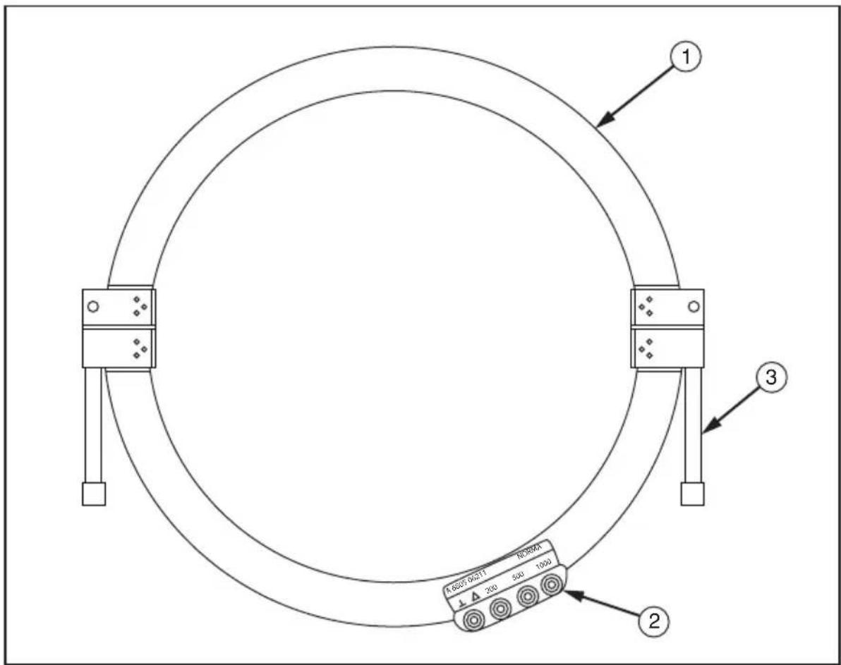
Figure 1. Features
evx01.eps
Table 1. Features and Functions
| Item | Description |
| 1 | Transformer half (2)Transformer end faces have bolts that pivot to aid in separating the Transformer halvesOne Transformer end face has a slotted bolt hole that allows the bolt to pivot out of the end face |
| 2 | Transformation ratio connections: ⊥, 200, 500, and 1000 |
| 3 | Fastener (2) |
Using the Split-Core Transformer
Installing Transformer around Pylon Footing
To install the Transformer around a pylon footing:
-
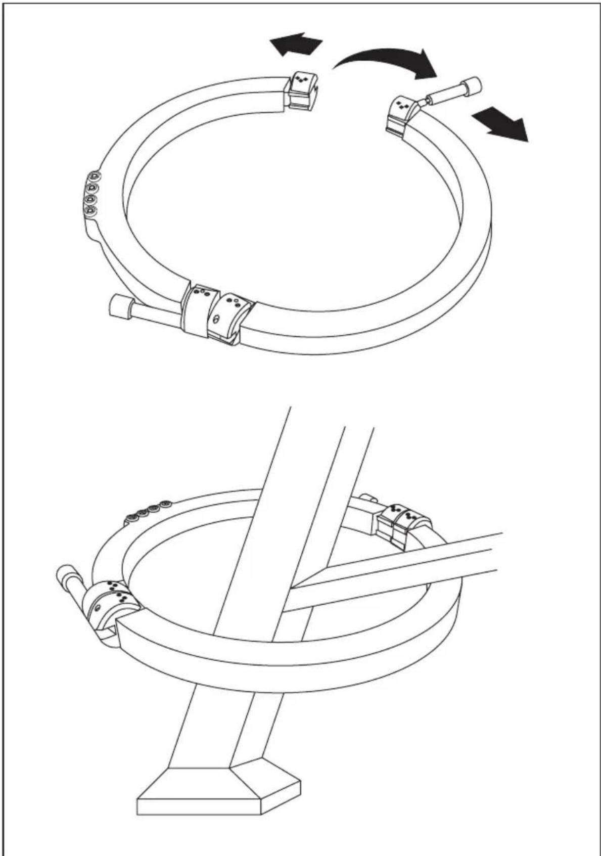
Loosen (or if required, remove) the fasteners. See Figure 2. If extra leverage is needed to loosen a fastener, insert a lever (like a small screwdriver) into the 4 mm bore hole in the fastener.
-
On the end face with the slotted bolt hole, pivot the fastener/bolt out of the way, and then separate the two halves of the Transformer. See Figure 2.
-
Install the Transformer around the pylon footing. See Figure 2.
Caution
- Damage to the Transformer end faces can greatly impair performance. Use care when joining the end faces together.
- Foreign substances on the end faces can distort measurement results. Before fastening together, ensure the end faces are clean. If required, see “Cleaning.”
- Airgaps between the end faces can distort measurement results. When fastening the end faces together, ensure the fasteners are tightened firmly.
- Join the two halves of the Transformer so the end faces meet. On the end face with the slotted bolt hole, pivot the fastener/bolt into place. If fasteners were removed, install the fasteners. Tighten fasteners firmly. See Figure 2.
If extra leverage is needed to tighten a fastener, insert a lever (like a small screwdriver) into the 4 mm bore hole in the fastener.
natural_image
Technical line drawings of a mechanical assembly, showing two sequential steps with arrows indicating motion (no text or symbols present)Figure 2. Installing Transformer Around Pylon
evx02.eps
Determining Transformation Ratio Connections
Before you connect the Transformer to the Tester, you need to determine a suitable transformation ratio for the minimum measuring and maximum parasitic currents expected to flow through the transmission line pylon.
The Transformer has 1000 windings, with connections at winding ratios of 1000, 500, 200 and 0 ( ). Depending on the combination of connections used, the Transformer can provide transformation ratios of 1:1000, 1:800, 1:500, 1:300, and 1:200.
See Table 2 to determine a suitable transformation ratio for the expected minimum measuring and maximum parasitic currents, and then see Figure 3 for the Transformer connections that will provide that ratio. These connections will be used for connecting the Transformer to the Tester's >c jack.
Note
Be sure to adjust your earth ground tester to the selected transformation ratio.
Table 2. Transformation Ratios
| Current | Ratio | ||||
| 1:1000 [1] | 1:800 | 1:500 | 1:300 | 1:200 | |
| Min. Measuring Current [2] | 0.50 mA | 0.40 mA 0.25 mA | 0.15 mA | 0.10 mA | |
| Max. Parasitic Current [3] | 3.0 A 2.4 A | 1.5 A 0.9 A | 0.6 A | ||
| [1] For nearly all selective earth ground resistance measurements, a ratio of 1:1000 is recommended[2] At 94, 105, 111, and 128 Hz[3] At 50, 60 and 16-2/3 Hz | |||||
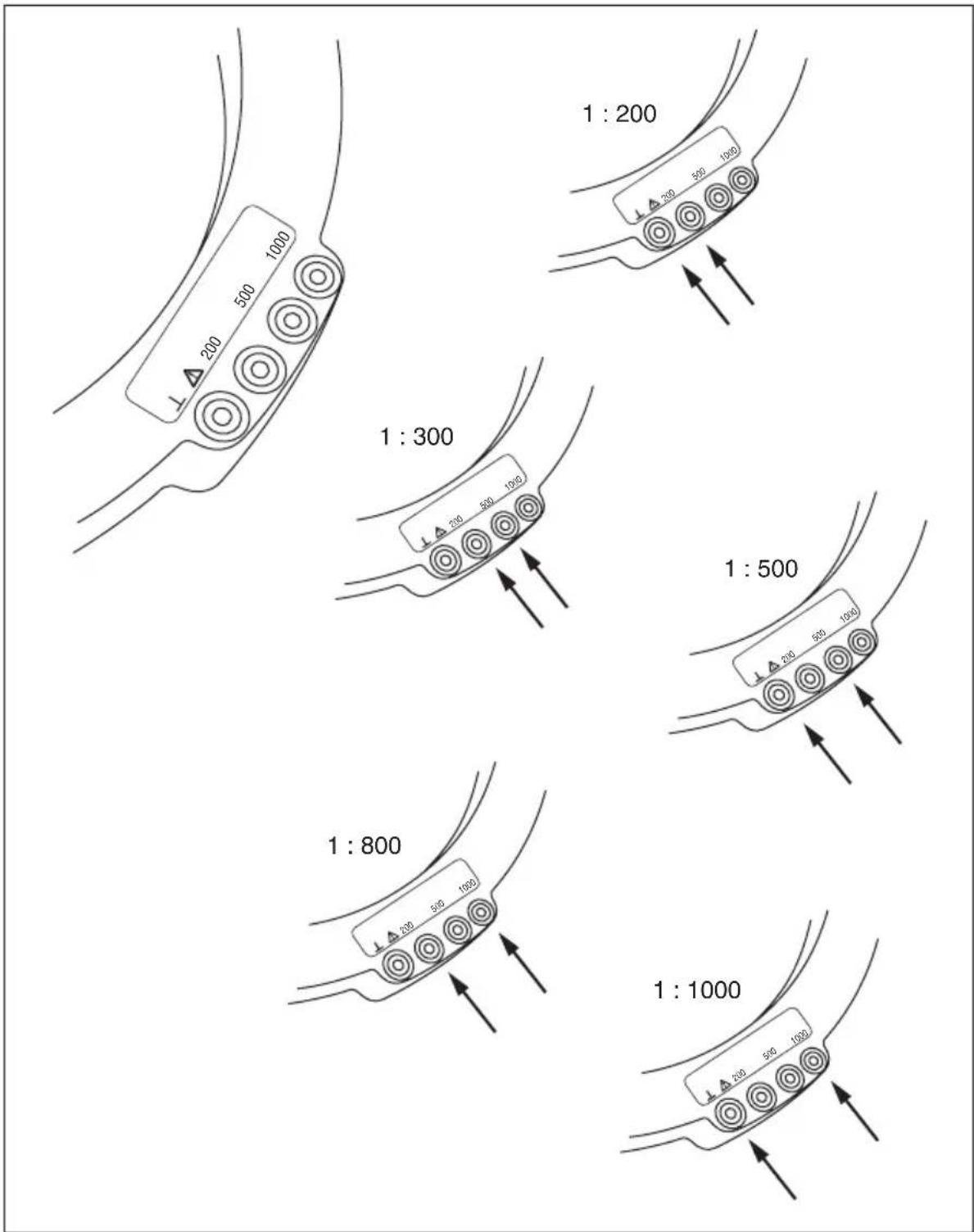
Figure 3. Transformation Ratio Connections
evx03.eps
Connecting Transformer to Earth Ground Tester
Caution
Corrosion and paint on a pylon can impede the connection between the contact clamp and the pylon's frame. When installing the contact clamp, ensure the tip of the clamp fastener penetrates all layers of paint and corrosion.
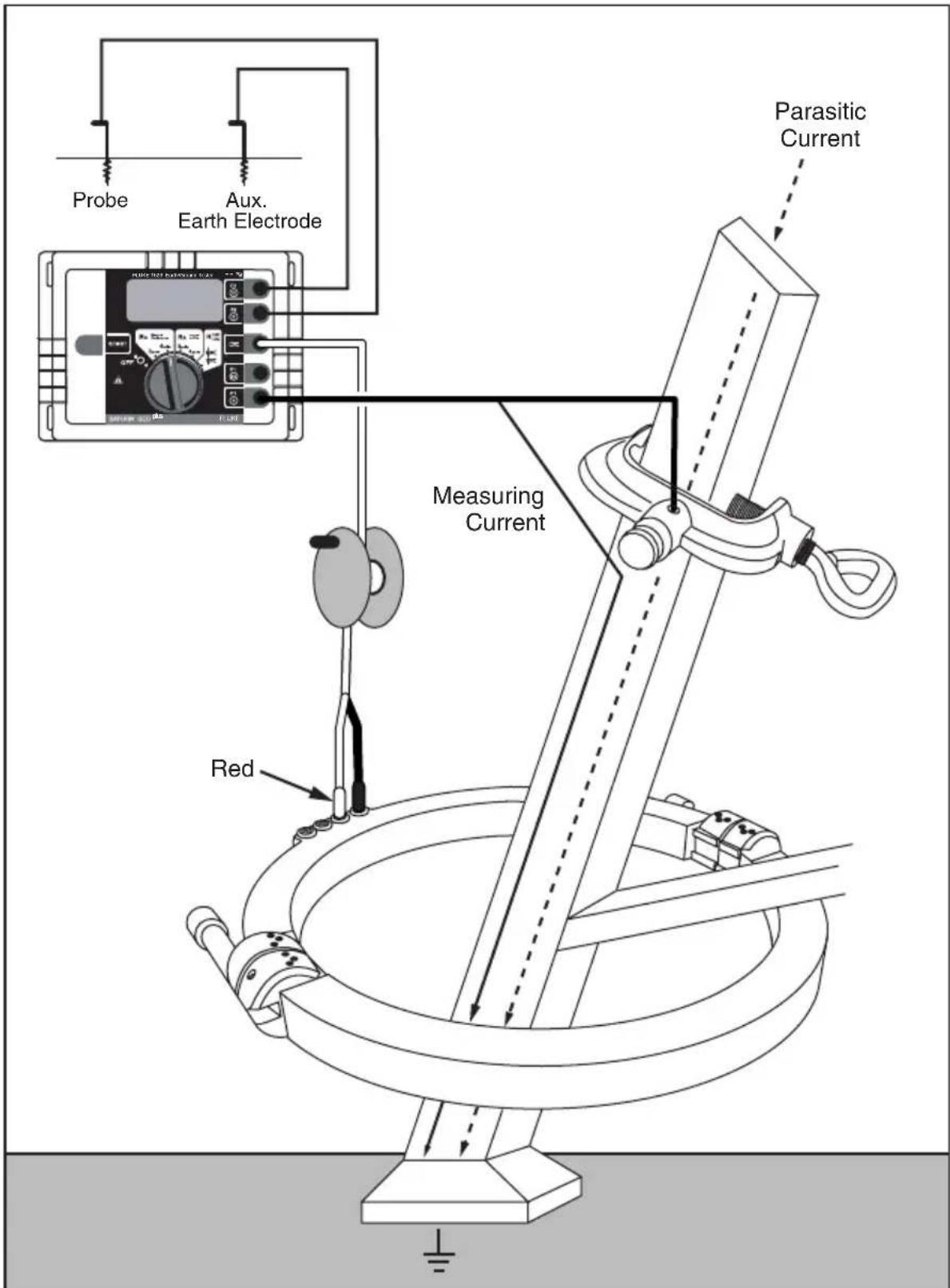
- Install the contact clamp to the pylon and tighten the clamp fastener. The contact clamp can now be used as the connection point for the Tester's earth ground electrode test lead. See Figure 4.
- Install a test lead from the Tester's earth ground electrode jack to the contact clamp. Plug the test lead into the bore hole in the clamp and tighten the tightening screw. See Figure 4.
For Fluke 1625 / 1623 GEO Earth/Ground Testers, the earth ground electrode jack is labeled C1 or E. - Install the 12-m (40-ft) test leads from the Tester's >C jack to the Transformer's transformation ratio connections. To determine which transformation ratio connections to use, see “Determining Transformation Ratio Connections.”
- In accordance with the Tester's users manual, install test leads from Tester to the probe and auxiliary earth electrode, and then perform your earth ground resistance measurement (RE).
evx04.eps
Figure 4. Test Measurement Setup
Maintenance
Only trained and qualified staff should perform maintenance on this instrument.
In all repair and reconditioning work, ensure the Transformer's design parameters are not modified to the detriment of safety, that only authorized parts are used, and that parts are reassembled to their factory-issued configuration.
Cleaning
Caution
To prevent damage to the Transformer when cleaning:
- Do not use strong cleaning detergents or solvents (like trichloroethylene).
- Do not allow liquid to get inside the instrument.
- Do not use sharp tools to clean the end faces.
If your Transformer requires cleaning, wipe it with a cloth lightly dampened with a mild rinsing agent.
Corrosion Prevention
To help prevent corrosion to the Transformer end faces, the cleavage planes should be lightly oiled.
Specifications
Note
Fluke reserves the right to modify specifications without notice for the purpose of product improvement.
General
Temperature Range
Working Temperature.... -10 °C to +50 °C (+14 °F to +122 °F)
Storage Temperature .... -30 °C to +60 °C (-22 °F to +140 °F)
Dimensions
Outer diameter.... 377 mm (15 in)
Inner diameter.... 310 mm (12 in)
Depth 30 mm (1.25 in)
Weight
Split-core transformer 4.9 kg (11 lb)
Total (with accessories and packaging).... 7.7 kg (17 lb)
Transformation Ratios 1:1000
1:800
1:500
1:300
1:200
Technical Data for Selective Earth Resistance Measurements
Insulation voltage 2 kV (core against secondary winding)
Max. current through split-core transformer ..... 3 A (primary current, transformation ratio 1:1000)
Additional Error for Selective Earth Resistance Measurements
Primary current >2.5 mA....±2 % (transformation ratio 1:1000)
Primary current <2.5 mA.... ±5 % (transformation ratio 1:1000)
Service
If your Transformer is operated and handled properly, it should not require servicing. However, if you suspect that the Transformer has failed, review this manual to ensure you are operating it correctly. If it still fails to operate properly, pack securely using the original packing material (if available) and forward, postage paid, to the nearest Fluke Service Center. Include a brief description of the problem. Fluke assumes no responsibility for damage in transit.
To locate an authorized service center, call Fluke using the phone numbers listed below:
USA: 1-888-99-FLUKE (1-888-993-5853)
Canada: 1-800-36-FLUKE (1-800-363-5853)
Europe: +31-402-675-200
Japan: +81-3-3434-0181
Singapore: +65-738-5655
Anywhere in the world: +1-425-446-5500
You may visit us on the World Wide Web at http://www.fluke.com.
To register your product, visit http://register.fluke.com.
Storage
When your Transformer is not going to be used, store it in the carrying case provided.
- Table of Contents
- Title
- Page
- List of Tables
- Table
- List of Figures
- Figure Title Page
- EI-162BN Split-Core Transformer
- Introduction
- Unpacking
- Packing
- Safety Regulations
- ⚠ Warning
- Symbols
- Accessories
- Features
- Using the Split-Core Transformer
- Installing Transformer around Pylon Footing
- Caution
- Determining Transformation Ratio Connections
- Note
- Connecting Transformer to Earth Ground Tester
- Maintenance
- Cleaning
- Corrosion Prevention
- Specifications
- General
- Temperature Range
- Dimensions
- Weight
- Technical Data for Selective Earth Resistance Measurements
- Additional Error for Selective Earth Resistance Measurements
- Service
- Storage
Brand : FLUKE
Model : EI-162BN
Category : Uncategorized