
X8500sc - Camera FLIR - Free user manual and instructions
Find the device manual for free X8500sc FLIR in PDF.


| Product Type | Infrared Science Camera |
| Model | FLIR X8500sc |
| Detector Type | InSb (1.5–5 μm) or SLS (3–12 μm) |
| Resolution | 1280 x 1024 (HD format) |
| Pixel Pitch | 12 μm |
| Frame Rate (Full Frame) | Up to 181 Hz |
| Dimensions (L x W x H) | 249 mm x 156 mm x 201 mm (with handle) / 147 mm (without handle) |
| Weight | 6.4 kg (14 lbs) without lens |
| Power Supply | 24 VDC nominal (20–28 V), <50 W steady state; AC adapter 100–250 VAC, 50/60 Hz |
| Digital Video Outputs | Camera Link Full, CoaXPress (dual 5 Gbps), GigE Vision, HDMI, HD-SDI, Composite (NTSC/PAL) |
| On-board Recording | 16 GB RAM buffer; SSD (500 GB included) for permanent storage |
| Filter Wheel | 4-position motorized warm filter wheel |
| Synchronization | Genlock, IRIG-B time stamp, Sync In/Out, Trigger In |
| Non-Uniformity Correction (NUC) | One-point, two-point, offset update; auto NUC with temperature/timer triggers |
| Operating Temperature | -20°C to +50°C |
| Storage Temperature | -55°C to +80°C |
| Shock & Vibration | 40 g, 11 ms half-sine; 4.3 g RMS random vibration |
| Maintenance | Clean body with soft cloth; lenses with approved solvents (acetone, ethanol); do not disassemble |
| Safety Warnings | Do not open camera; avoid imaging intense sources (sun, lasers); handle as static-sensitive device |
| Included Accessories | Power supply, GigE cable, HDMI cable, AUX breakout cable, filter wrench, SSD, transit case |
Frequently Asked Questions - X8500sc FLIR
User questions about X8500sc FLIR
0 question about this device. Answer the ones you know or ask your own.
Ask a new question about this device
Download the instructions for your Camera in PDF format for free! Find your manual X8500sc - FLIR and take your electronic device back in hand. On this page are published all the documents necessary for the use of your device. X8500sc by FLIR.
USER MANUAL X8500sc FLIR
X-Series Science Camera
User's Manual
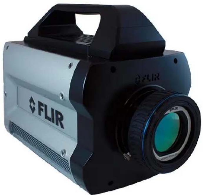
natural_image
Exterior view of a FLIR (Advanced Light Source) camera with visible lens and control panel (no text or symbols beyond branding)This document contains no export-controlled information.
Document Number: 4221772
Version: C
Issue Date: April 8, 2020
FLIR Systems, Inc.
9 Townsend West,
Nashua, NH 03063
Support: 1-800-GO-INFRA (800-464-6372)
http://flir.custhelp.com
Service: 1-866-FLIR-911
www.flir.com
©2020 FLIR Systems, Inc.
Table of Contents
1 REVISION HISTORY ......6
2 INTRODUCTION....7
2.1 Camera System Components....7
2.2 Camera Models 7
2.3 System Overview....8
2.4 Key features of the X-Series science cameras 9
3 WARNINGS AND CAUTIONS....12
4 INSTALLATION....13
4.1 Basic Connections....13
5 X-SERIES CAMERA CONTROLLER....17
5.1 Online Help....18
5.2 Menu Bar....18
5.2.1 Tools Menu....18
5.2.1.1 Advanced Time Controls....20
5.2.2 Help Menu 20
5.3 Basic User Mode 22
5.3.1 Status Page 23
5.3.2 Setup Page 23
5.3.3 Correction Page....25
5.4 Advanced User Mode 26
5.4.1 Status Page 26
5.4.2 Setup Page 27
6.1 Mechanical Dimensions....69
6.2 Electrical – X8500 and X6900 Series....72
6.2.1 Power Switch....72
6.2.2 Solid State Drive....73
6.2.3 Status Lights....73
6.2.4 Gigabit Ethernet....74
6.2.5 MicroSD....74
6.2.6 USB Client 74
6.2.7 HDMI Video 74
6.2.8 Power Interface 75
6.2.9 Camera Link ^® Video Output....75
6.2.10 Auxiliary Connector/Breakout Cable 76
6.2.11 Record Trigger....78
6.2.12 CoaXPress (CXP) Video Output [X6900/X8500 only]....78
6.2.13 Sync In....78
6.2.14 HD-SDI [X6900/X8500 only]....79
6.2.15 Composite Video Output [X6900/X8500 only]....79
6.2.16 Sync Out....79
6.2.17 Genlock Input [X6900/X8500 only]....80
6.2.18 IRIG Input [X6900/X8500 only]....80
7 FILTER WHEEL....81
8 SPECIFICATIONS 83
8.1 Interface 83
8.2 Windowing Capacity....83
8.3 Acquisition Modes and Features....84
8.4 Analog Video....86
8.5 Performance Characteristics 87
8.6 Non Uniformity Correction 87
8.7 Detector/FPA....88
8.8 General Characteristics 88
9 MAINTENANCE....90
9.1 Camera and Lens Cleaning....90
9.1.1 Camera Body, Cables and Accessories....90
9.1.2 Lenses 90
1 Revision History
| Version | Date | Initials | Changes |
| A | 07/09/2019 | AAR | Initial Release |
| B | 01/06/2020 | AAR | Correction to Aux cable pinout, 1308 gain states |
2 Introduction
Thank you for choosing a FLIR X-series science camera! The X-series cameras are some of the fastest commercial infrared cameras in the world, and they were designed with the high-end infrared camera user in mind.
2.1 Camera System Components
The X-series infrared camera and its accessories are delivered in a box which typically contains the items below. There may also be additional items that you have ordered such as lenses, software, CDs, etc.
| Description | FLIR Part Number |
| X6800sc Camera | 29420-2xx (InSb) |
| X6900sc Camera | 29267-2xx (InSb) or 29421-2xx (SLS) |
| X8500sc Camera | 29422-2xx (InSb) or 29428-2xx (SLS) |
| Power supply, 24V, 4A | 24123-000 |
| AC line cord | 24124-000 |
| Gigabit Ethernet Cat-6 cable, 2m length | 24277-000 |
| AUX Breakout Cable | 4212860 |
| Bayonet mount plug | 4142249 |
| Laboratory calibration plate | 261-0005-00 |
| 500GB SSD | 4142223 |
| SSD to USB cable | 4142222 |
| Filter wheel wrench | C1004.M202 |
| HDMI video cable, 6-ft | 4142224 |
| Water-resistant transit case | 24043-005 |
| Documentation CD | N/A |
2.2 Camera Models
The X-series is a camera family. There are several different models, ensuring a wide variety of customer needs can be met. The X6800-series cameras are a slower, less expensive version of the X6900-series series. The X6900-series cameras are 640x512 cameras built for very high frame rates. The X8500-series cameras have an HD focal plane array
| Model | Description | FLIR Part Number |
| X6800sc | f/2.5Broadband (InSb: 1.5-5μm response) | 29420-200 |
| X6801sc | f/2.5InSb: 3-5μm response | 29420-201 |
| X6802sc | f/4.1Broadband (InSb: 1.5-5um response) | 29420-202 |
| X6803sc | f/4.1InSb: 3-5μm response | 29420-203 |
| X6900sc | f/2.5Broadband (InSb: 1.5-5μm response)Broadband (SLS: 3-12μm response)* | 29267-20029421-200 |
| X6901sc | f/2.5InSb: 3-5μm responseSLS: 7.5-12μm response* | 29267-20129421-201 |
| X6902sc | f/4.1Broadband (InSb: 1.5-5um response)Broadband (SLS: 3-12μm passband)* | 29267-20229421-202 |
| X6903sc | f/4.1InSb: 3-5μm responseSLS: 7.5-12μm response* | 29267-20329421-203 |
| X8500sc | f/2.5Broadband (InSb: 1.5-5μm response)Broadband (SLS: 3-12μm response)* | 29422-20029428-200 |
| X8501sc | f/2.5InSb: 3-5μm responseSLS: 7.5-12μm response* | 29422-20129428-201 |
| X8502sc | f/4Broadband (InSb: 1.5-5um response)Broadband (SLS: 3-12μm passband)* | 29422-20229428-202 |
| X8503sc | f/4InSb: 3-5μm responseSLS: 7.5-12μm response* | 29422-20329428-203 |
| *NOTE: SLS upper cutoff tolerance is +/- 0.5um | ||
2.3 System Overview
The X-Series infrared camera systems have been developed by FLIR to meet the needs of the research, industrial and range phenomenology communities.
The X8500sc camera makes use of FLIR's advanced ISC1308 readout integrated circuit (ROIC), mated to an Indium Antimonide (InSb) detector to cover the shortwave and midwave infrared bands and an SLS array for longwave infrared. The X6800 and X6900 cameras use the ISC0804 ROIC.
The X8500sc camera utilizes an HD format, 1280x1024 array with 12μm pixel pitch. The X6800 and X6900 cameras use a large format, 640x512 array with 25um pixels. The architectures of the camera systems fully exploit a rich palette of features available in both the 0804 and 1308 ROICs to support the specialized needs of high-end research.
The X-Series is a stand-alone imaging camera that interfaces to host PCs using standard interfaces, including Gigabit Ethernet, Camera Link®, and CoaXpress (CXP). The X-Series cameras are all GenICam compliant. An SDK is also available, which makes it possible for the system designer to write their own camera controller and acquire image data with their own custom application.
2.4 Key features of the X-Series science cameras
Improved Linearity to Zero Well-Fill
Typical direct injection ROIC designs exhibit a non-linear response when the signal drops below 10% of well-fill. Both the ISC0804 and ISC1308 ROICs provides linear response even at very low signal levels. This results in an increased linear dynamic range, much better NUC performance at low signal levels and it makes it easier to perform a user calibration of the camera.
Fast Frame Rates
The X6900 and X8500sc cameras feature fast pixel clocks: 355 Megapixels per second, which enable the X6900 camera to output 1000 frames per second at 640x512, and the X8500 camera to output >180 frames per second at a frame size of 1280x1024 pixels. The X6800 series frame rate is limited to approximately half the X6900 frame rate, but it has the same 355 Megapixels per second pixel clock speed.
14-Bit Digital Image Data
The X-Series camera systems are all built around high-performance 14-bit A/D converters, preserving the full dynamic range of the FPA.
Windowing Capability
Higher frame rates are available by windowing down at the Focal Plane Array (FPA) level. Semi-arbitrary size and location of windows are available, limited only by the intrinsic characteristics of the readout.
Presets
Up to four presets and their associated parameters such as integration time, frame rate, window size and window location are available for instant selection with a single command. These presets can be used in either Superframing or Preset Sequencing modes.
Factory Calibrations
Most variants of the X-Series cameras can be purchased with radiometric calibrations that are performed in the calibration laboratory in Niceville, Florida using NIST-traceable calibration sources. The calibrations translate the raw digital data from the sensor into radiometric images that can be interpreted by software into radiance and temperature images. These factory radiometric calibrations are stored inside the camera electronics and are linked to high-quality stored factory NUCs. The radiometric calibrations have temperature drift correction built in that utilizes various temperature sensors inside the camera body and on the lens interface to compensate for changes in the optics self-radiation levels caused by changes in the camera and optics temperatures.
Independently Adjustable Frame Rates
Frame rate is user selectable from 0.0015 Hz up to the maximum allowed for the selected window size.
Multiple Triggering Modes and Synchronizing Interfaces
The X-Series cameras provide different interfaces to support maximum flexibility for synchronizing the camera to external events, as well as synchronizing external events to the camera.
- Sync In (TTL)
▪ Built-in IRIG timing decoder (not in X6800 series) - Genlock input (SD or HD) (not in X6800 series)
- Sync Out
Adjustable Digital Gains and Offsets
The X-Series cameras allow the user to adjust digital gains and offsets per preset, making it possible to map only the linear portion of the FPA to the full range of digital count values.
Multiple Control Options
The X-Series cameras can be controlled with the supplied control module within ResearchIR, using the optional BHP SDK or with a third-party toolkit that support GenICam. The following ports can be used for controlling the X6900 and X8500-series cameras:
▪ Gigabit Ethernet port (GenICam)
- Camera Link® serial port (GenCP)
- CoaXpress (GenICam)
- USB-2 port
- Traditional RS-232 asynchronous serial port (GenCP)
The X6800 camera supports:
- Gigabit Ethernet port (GenICam)
- Camera Link® serial port (GenCP)
- USB-2 port
- Traditional RS-232 asynchronous serial port (GenCP)
Multiple Video Outputs
The X6900 and X8500 cameras feature multiple independent and simultaneous video outputs:
- Digital Data – Camera Link® Full
- Digital Data – Gigabit Ethernet
- Digital Data -- CoaXpress
- Digital Video – HD-SDI (1080p or 720p)
- Digital Video – HDMI (1080p or 720p)
- Analog Video – Composite video (NTSC or PAL)
The X6800 cameras have the following video outputs:
- Digital Data – Camera Link® Full
- Digital Data – Gigabit Ethernet
- Digital Video – HDMI (1080p or 720p)
Support for Camera Link Full or CoaXpress interfaces
The X6900 and X8500 cameras are the first commercial IR cameras to offer both Camera Link Full and CoaXpress (CXP) interfaces on the same camera. Both interfaces are simultaneously active.
The X6800 series has the Camera Link interface, but not CoaXpress.
Video Color Palettes
The X-Series cameras support a selection of standard and user-defined color palettes for the analog video and HD-SDI outputs.
X6800 only has HDMI output.
Video Overlay
X6900 and X8500: A configurable video overlay provides the user with IRIG time and camera status symbology on the analog video without needing to use the GUI.
X6800: A configurable video overlay provides the user with camera status symbology on the HDMI video output without needing to use the GUI.
Ruggedized Construction
The X-Series cameras are packaged in semi-sealed enclosures with integral forced air heat exchangers.
Digital Detail Enhancement (DDE)
DDE is an analog video AGC mode that provides a significant improvement to scene detail and contrast.
On-Camera NUCs with Auto Update
NUCs can be stored in camera memory and can be applied independently to the various digital and video outputs. The camera can be configured to automatically update the NUC using the internal flag based on a change of an internal temperature sensor and/or a timer.
IRIG Time Stamp (TSPI Accurate)
The X6900 and X8500 cameras can automatically sync to a standard IRIG-B analog time signal. The time stamp jitter is less than 10 microseconds. The time is encoded in the digital image header and can also be displayed on the analog video overlay.
The X6800 camera does not support an IRIG-B input.
4-position filter wheel
The X-Series cameras have internal motorized filter wheels that can position a warm filter between the lens and detector. The filters can be installed by the user and the filter holders support automatic identification.
On-board recording with Solid State Drive (SSD) storage
The X-Series cameras have on-board 16GB RAM buffers that can record at any supported frame rate with zero dropped frames. Data in the RAM buffer can be played back over any digital data or video interface or can be stored to the internal SSD drive.
The SSD system uses standard commercial SSDs used in PCs and laptops. The SSD is readily removed from the camera. The SSD can then be connected to the PC using a standard USB/2.5" drive SATA cable (provided). The drive data can be accessed using the provided ResearchIR software.
3 Warnings and Cautions
For best results and user safety, the following warnings and precautions should be followed when handling and operating the camera.

Warnings and Cautions:
Do not open the camera body for any reason. Disassembly of the camera (including removal of the cover) can cause permanent damage and will void the warranty.
Great care should be exercised with your camera optics. Refer to Chapter 9 for lens cleaning.
➢ Operating the camera outside of the specified input voltage range or the specified operating temperature range can cause permanent damage.
The camera is not completely sealed. Avoid exposure to dust and moisture and replace the lens cap when not in use.
Do not image extremely high intensity radiation sources, such as the sun, lasers, arc welders, etc.
The camera is a precision optical instrument and should not be exposed to excessive shock and/or vibration. Refer to Section 8.8 for detailed environmental requirements.
The camera contains static-sensitive electronics and should be handled appropriately.
4 Installation
4.1 Basic Connections
All connections to the X-series cameras are located on the Back Panel. Although the X6900 and X8500 cameras have a large number of connections, only a small number are required for basic operation. The X6800 is a simplified version of the X6900 camera with fewer connections.
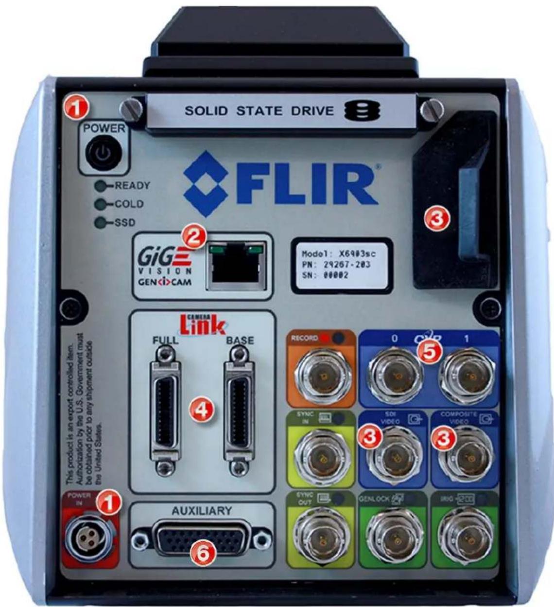
| Item | Category | Description |
| 1 | Power | Power button. DC power connector.Plug in the AC power supply to a standard outlet. The power supply is compatible with 120V/60Hz and 240V50Hz AC power. Plug adapters can be used for different regions. Connect the DC power cable between the power supply and the power connector located on the rear panel of the X-series camera. Turn on the camera by pressing the power button on the rear panel. The button will illuminate to indicate that the unit is ON. |
| 2 | Digital Data | Gigabit EthernetThe X-Series cameras have a Gigabit Ethernet interface that is GigE Vision compliant. Use a regular CAT5e, CAT6 or CAT7 Ethernet patch cable. If a crossover cable is used, the camera interface will automatically detect and configure itself to work with this kind of cable. The GigE interface is not capable of handling the full data rate of the camera. The interface can handle about 30Hz at the X8500 camera's full resolution and about 125Hz with the X6900/X6800 cameras, but results may vary depending on the host computer. |
| 3 | Video | HDMI, HD-SDI, Composite (NTSC/PAL) |
| 4 | Digital Data | Camera Link FullThe X-Series cameras have an industry standard Camera Link Full interface using MDR connectors. This interface can handle the full data rate of any of the cameras. |
| 5 | Digital Data | CoaXPressThe X8500sc and X6900sc cameras use dual 5Gbps links with BNC connectors. This interface can handle the full data rate of the cameras. |
| 6 | Auxiliary | This is the Auxiliary connector which is described in Section 6.2.10. |
The X6800 series cameras have fewer connections:
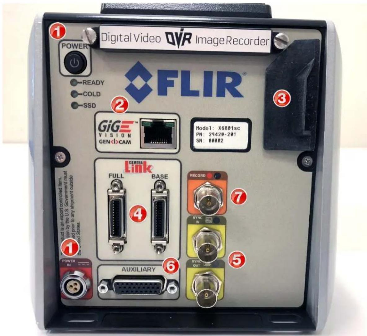
| Item | Category | Description |
| 1 | Power | Power button. DC power connector.Plug in the AC power supply to a standard outlet. The power supply is compatible with 120V/60Hz and 240V50Hz AC power. Plug adapters can be used for different regions. Connect the DC power cable between the power supply and the power connector located on the rear panel of the X6800sc camera. Turn on the camera by pressing the power button on the rear panel. The button will illuminate to indicate that the unit is ON. |
| 2 | Digital Data | Gigabit EthernetThe X6800sc has a Gigabit Ethernet interface that is GigE Vision compliant. Use a regular CAT5e or CAT6 Ethernet patch cable. If a crossover cable is used, the camera interface will automaticallydetect and configure itself to work with this kind of cable. The GigE interface is not capable of handling the full data rate of the camera. It can handle about 125Hz at full resolution. |
| 3 | Video/USB | HDMI video output, USB-2 port and microSD card slot (not yet implemented) |
| 4 | Digital Data | Camera Link FullThe X6800sc has an industry standard Camera Link Full interface using MDR connectors. This interface can handle the full data rate of the camera. |
| 5 | Sync | Sync input and output connectors |
| 6 | Auxiliary | This is the Auxiliary connector which is described in Section 6.2.10. |
| 7 | Record | This record input will trigger the recording to the internal RAM buffer I the camera. The input can be a contact closure or a rising-edge TTL pulse. |
5 X-Series Camera Controller
The X-Series Camera Controller (also called the Graphical User Interface or GUI) can be accessed from within the ResearchIR software. Once the user is connected to the camera, a mini controller will be visible in the left pane:
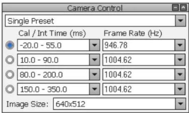
This controller will have basic controls for the most commonly used settings, like integration time, frame rate, preset selection, and window size. Clicking the "More" button will display the full camera controller. The rest of this chapter will describe the full camera controller features in detail.
The camera control pane shown above indicates that factory radiometric calibrations are loaded into the four presets of the camera. The values shown are temperature ranges. For example, the first preset is designed to measure object temperatures from -20C to 55C, the second from 10C to 90C. These factory calibrations are associated with NUC files which are stored in the camera. When the camera is connected to ResearchIR software, the software will detect the loaded calibration and interpret the raw image data into radiometrically calibrated images in radiance or temperature units. This is described more fully in the ResearchIR user manual.
The full camera controller can operate in two user modes, Basic or Advanced. The Basic mode gives the typical camera controls most users need. For advanced system requirements that exercise the full capabilities of the camera, the Advanced mode is used. The user mode can be selected from the Tools>>User Mode menu. In both modes, the menu bar is the same.
The Status pages looks similar in both modes, but the Advanced mode gives the user much more control of advanced camera features.
NOTE: The X6800sc uses the same camera controller software as the X6900sc. The X6800sc is missing several features found in the X6900sc but the controls for these functions may still be visible in the GUI. For example, the X6800sc has a precision image timestamp which may be referred to as a "IRIG" time. However, this time stamp cannot be synchronized to an external IRIG-B signal. It can only be set to reflect the PC or camera real-time clock (RTC) but will only free-wheel after being set. The IRIG timestamp will be set to the camera RTC automatically at power-up.
GUI controls for Genlock should not be used because this input is not available. The X6800sc only supports HDMI. Choosing options for SDI or composite video will result in no video to be displayed.
The X6800sc has a reduced maximum framerate compared to the X6900sc. Various screenshots within this manual may show frame rates that are beyond what the X6800sc supports.
5.1 Online Help
The X-Series Camera Controller provides two online help options. First there is this manual which can be accessed via the Help menu. Second, when placing the mouse cursor over a particular control, a Tooltip will be displayed giving a basic description of the control.
5.2 Menu Bar

The menu bar is the same for both Basic and Advanced User Modes.
| Save State (name) | Saves the camera state to the current (name). This state will be reloaded at power up. Stored in flash memory. | ||
| Camera Tools HelpSave State (Snake!)Save State AsLoad StateManage StatesLoad Factory Defaults | Save State As | Saves the current camera state to a name chosen by the user. State names other than (name) may be loaded manually. Stored in flash memory | |
| Load State | Load a state from flash memory. | ||
| Manage States | Rename or delete states from camera memory. | ||
| Load Factory Defaults | Loads factory defaults for all camera Settings and NUCs. The factory defaults cannot be modified by the user. | ||
NOTE: Camera states contain information about all configurable camera parameters. They do not contain the NUC data, but they do contain the filenames of the currently loaded NUCs. These NUCs will be reloaded with the state; however, if the NUCs are changed, deleted, or renamed, the state may not be able to load the NUCs.
5.2.1 Tools Menu
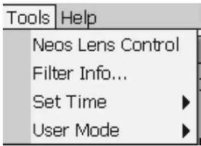 | NEOS Lens Control | Activates control link to certain motorized lenses |
| Filter Info | Shows ID info for filters in wheel | |
| Set Time | Options for setting time | |
| User Mode | Select Basic or Advanced mode | |
| Set PC Time to Camera Time | Set PC Time toCamera Time | Sets the PC clock to the time from thecamera IRIG clock.[Note: For the X6900 and X8500 cameras, at power up, the IRIG clock is automatically synchronized to the cameras Real Time Clock (RTC).][Note: If the current PC user account does not have permission to access the system clock, this function will not work.] |
| Set Camera Time to PC Time | Sets the camera RTC/IRIG clocks to the time from the PC clock. If the camera IRIG clock is synchronized to an external source the time will momentarily blip if this function is selected and it will then resynchronize automatically with the IRIG source. (X6800 has RTC only) | |
| Advanced... | Allows user to manually set the IRIG and RTC clocks in the camera. See Section 5.2.1.1 | |
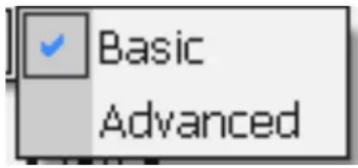 | User Mode >> Basic | Provides a limited subset of controls. All controls on a single page to minimize time needed to find a control. |
| User Mode >> Advanced | Activates all controller features. |
NOTE: The X-series cameras have two internal clocks: A Real Time Clock (RTC) and an IRIG clock. The RTC is a low resolution clock used to keep system time. The RTC has a battery backup and will retain time while the camera is off. The IRIG clock is a high resolution (microsecond) clock. This clock does not have a battery backup but at power up the IRIG clock is initialized to the current RTC time and will free-wheel until an IRIG signal is applied to the camera. The X6800 IRIG clock cannot be synchronized to an external IRIG time source.
5.2.1.1 Advanced Time Controls
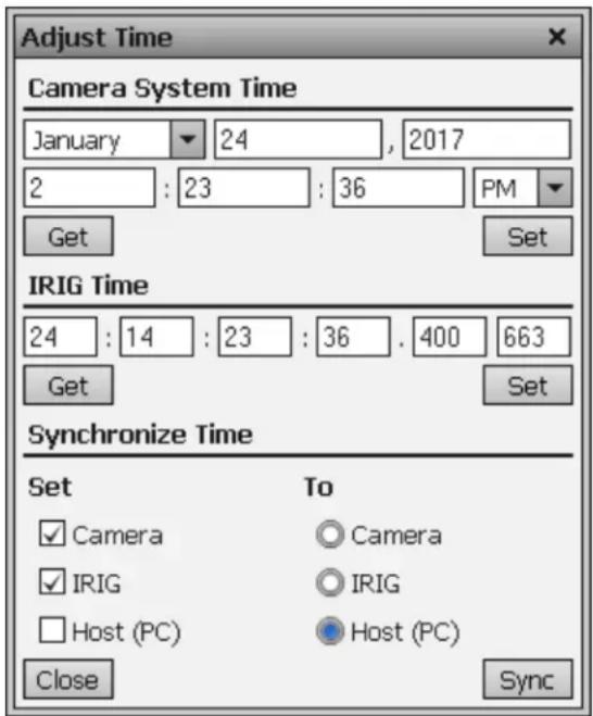
This dialog is accessed using the Tools>>Set Time>>Advanced menu options. This allows the user to directly set the cameras system time, and IRIG time. Under the Synchronize Time section the user can select various clocks on the left and synchronize them to a clock from the right. In the example below, the "Sync" button is pressed, the Camera System and IRIG clocks will be synchronized to PC time (including local time zone).
NOTE: Setting the PC time requires your PC user account to have certain permissions set. If you do not have sufficient permission, then this function will not work.
5.2.2 Help Menu
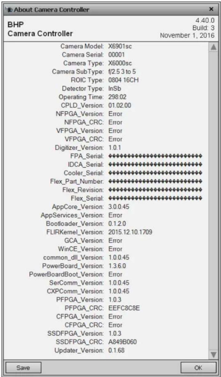
The “About” menu item shows a dialog indicating the current controller version number. If the controller is connected to a camera a list will be displayed that shows all versions of software and firmware in the camera. The “Save” button allows the user to create a text file with this version information.
5.3 Basic User Mode
The Basic User mode enables a limited set of controls, thus greatly simplifying the controller interface. Most controls will be disabled until the user connects to the camera using the Camera>>Connect menu option.
| Features supported in Basic Mode | |
| Manually Setting Integration Time | YES |
| Setting Window Size | Limited, Four window choices |
| Setting Frame Rate | YES |
| On-camera NUC | Must be enabled |
| NUC Management | None (Fixed NUC name) |
| NUC Controls | 1-pt, 2-pt, Update Offset |
| External Sync | Only using SYNC IN BNC |
| Preset Sequencing/Superframing | NO |
| Independent Video and Data NUC | NO |
| Analog AGC | Manual Linear, PE, DDE,Brightness/Contrast, no ROI mode |
| AGC Filter | ON/OFF Only |
| Temporal Filter | ON/OFF Only |
| Invert/Revert | NO |
| Digital Zoom | YES |
| Color Palette | YES |
| Overlay Controls | NO |
5.3.1 Status Page
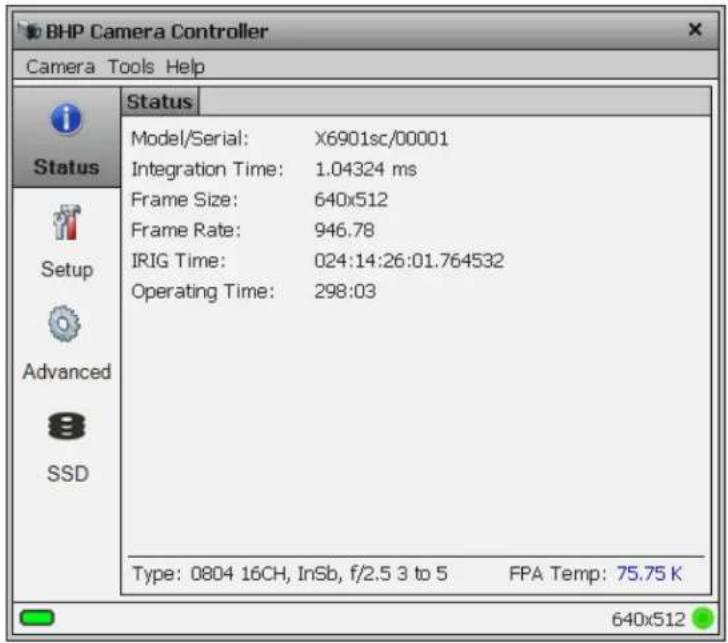
The Status Page gives general information about the camera state including camera type, camera time, integration time, frame size, and frame rate. This page also shows the current IRIG time and the camera operating hours. At the bottom of the window the detailed camera type is displayed as well as the FPA operating temperature. The indicator at the bottom left will be green when a connection to a camera is established and will blink during communication.
5.3.2 Setup Page
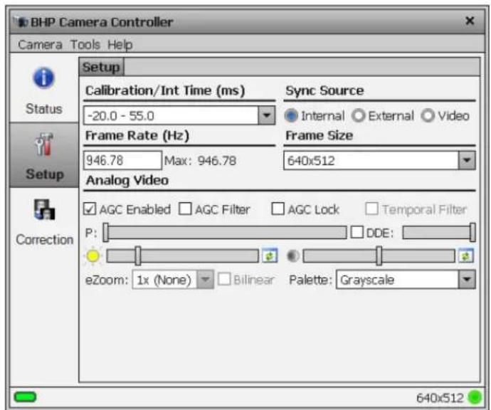
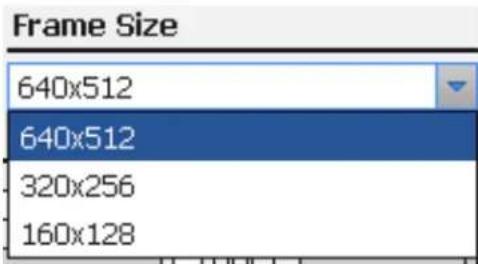
The Setup page allows the user to set integration time, frame rate, frame size, and Sync source. Frame size selection is limited to the drop list. The video output source cannot be chosen but AGC can be configured.
The frame size selections are here, 1280x720 is an option and is not shown:
| Basic Setup Page Controls | |
| Integration time | Enter integration (exposure) time in milliseconds. If factory calibration is active, then this will be a dropdown list of available calibration ranges. |
| Sync Source | Internal: internal clock used to generate FPA frame rateExternal: SYNC IN signal used to generate FPA frame rateVideo: Internal video clock used to generate FPA frame rate |
| Frame Rate | Sets value of internal frame rate. Not used for External or video sync modes |
| Frame Size | In basic mode only 4 window sizes are available. |
| AGC Enabled | Turns video Automatic Gain Control (AGC) on and off. Several AGC algorithms are available in the Advanced mode. |
| AGC Filter | The AGC Filter controls how quickly the AGC will respond to scene changes. In basic mode can only be turned on/off. Uses settings from Advanced mode |
| AGC Lock | AGC normally computed for each image frame. AGC Lock freezes AGC setting to current values. |
| Temporal Filter | Not available on X-series |
| PE | If Plateau Equalization (PE) AGC is active in Advanced mode, “P” controls the strength of the AGC. Move slider to the right for more aggressive AGC. |
| DDE | If Digital Detail Enhancement (DDE) AGC is active in Advanced mode, “DDE” controls the strength of the AGC. Move slider to the right for more aggressive AGC. Checkbox enables/disables DDE |
| Brightness | Adjusts video encoder brightness level. No available for all video outputs |
| Contrast | Adjusts video encoder contrast level. No available for all video outputs |
| eZoom | Selects level of “digital” zoom |
| Bilinear | If disabled, eZoom uses pixel replication to create zoom. If enabled, zoom uses bilinear interpolation for eZoom. |
| Palette | Allows selection of false color palette for. Same palette used for all video outputs |
5.3.3 Correction Page
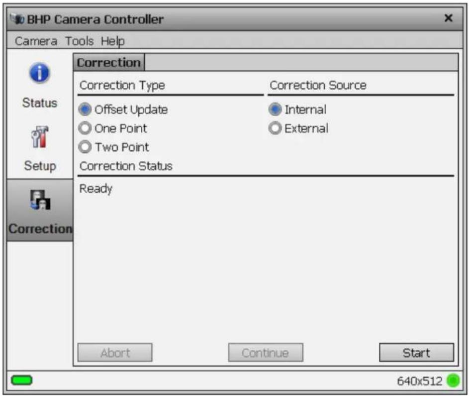
The Correction Page provides functions related to performing an on-camera NUC. Three correction types are available and are described in the table below. The Correction Status area will show messages and prompt the user to complete certain tasks such as place a blackbody in the field of view.
To perform an on-camera NUC, select a Correction Type and Correction Source and press Start.
| Correction (NUC) Types | |
| Offset Update | Retains the current NUC gain terms and updates the offset terms. Uses a single NUC source. Retains the current bad pixel (BP) correction. |
| One Point | Sets the gain terms to “1” and computes the offset terms. Uses a single NUC source. Does not compute a BP correction. |
| Two Point | Sets both the gain and offset terms. Uses two NUC sources. Computes a bad pixel correction. |
| Correction Sources | |
| Internal | Use the internal flag as the NUC source. The flag is not temperature controlled and floats at camera internal |
| External | Use an external blackbody as the NUC source. Program will prompt the user to place each source in front of the camera. NUC source needs to fill the entire field of view. |
| Correction Process Controls(will be disabled if command not available) | |
| Abort | Stops the NUC process. |
| Continue | When prompted for an action, click “Continue” when action has been performed. |
| Start | Starts the selected NUC process. |
5.4 Advanced User Mode
The Advanced User Mode exposes the full functionality of the camera controller. The controller looks similar to the basic mode, but additional tabs will appear on each page. This will be the preferred mode for most users.
5.4.1 Status Page
The Status page is the same in both Basic and Advanced user modes. The Status Page gives general information about the camera state including camera type, camera time, integration time, frame size, and frame rate. This page also shows the current IRIG time and the camera operating hours. At the bottom of the window the detailed camera type is displayed as well as the FPA operating temperature. The indicator at the bottom left will be green when a connection to a camera is established and will blink during communication.

5.4.2 Setup Page
In Advanced mode, the Setup page allows the user to configure each camera preset, set integration time (or calibration range), frame rate, windowing, sync, and filter wheel options. The Setup Page has four tabs: Presets, Window, Sync, and Filter/Flag.
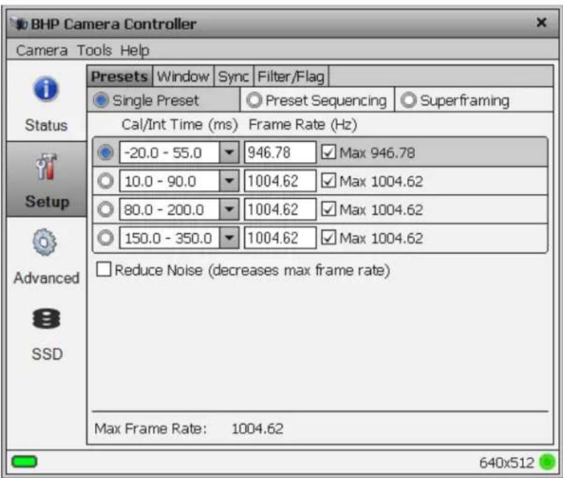
Before talking about the details of the Setup page, a brief discussion about frame rates and integration time will be helpful.
Frame rate is the number of images taken by the camera per second. The Integration time is the “exposure time”, the period of time the camera actually views the scene. Achievable frame rates are based on camera settings, camera overhead, and integration settings. A brief review of the processes that occur during a frame is needed to understand how to determine maximum achievable frame rates.
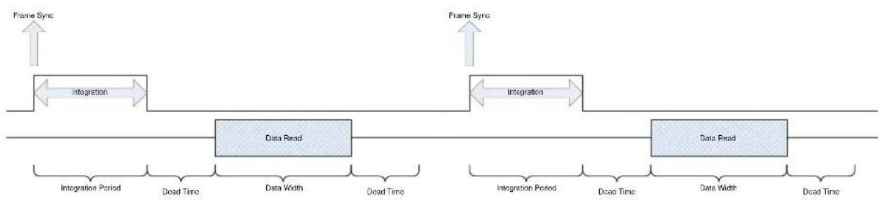
There are two basic integration modes, Integrate Then Read (ITR) and Integrate While Read (IWR). Integrate Then Read is the most basic behavior of the camera and shows the process most clearly. As seen in the ITR process diagram below, the frame generation process begins with a Frame Sync. The camera then integrates the set amount of time, goes through a fixed dead time, transmits data, goes through a second fixed dead time, and then is ready to start the process over again. Here you see the camera first completes the integration process and then reads the data out, hence the term Integrate Then Read.
flowchart
graph LR
    A["Frame Sync"] --> B["Integration"]
    B --> C["Data Read"]
    C --> D["Integration Period"]
    C --> E["Dead Time"]
    C --> F["Data Width"]
    C --> G["Dead Time"]
    H["Frame Sync"] --> I["Integration"]
    I --> J["Data Read"]
    J --> K["Integration Period"]
    J --> L["Dead Time"]
    J --> M["Data Width"]
    J --> N["Dead Time"]
ITR Frame Generation Process
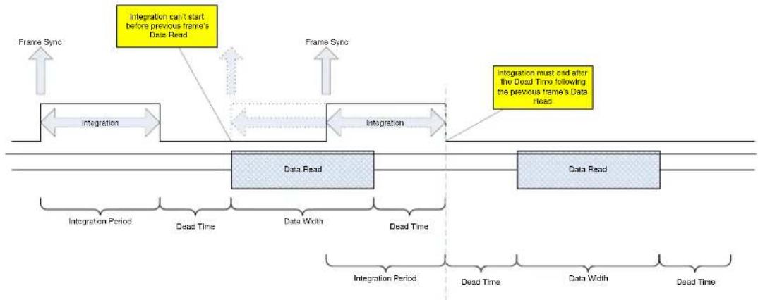
The Integration and the Data Readout periods can be thought of as two separate processes; however, they are linked together by certain timing requirements. What this means is the camera can integrate for a period, start the data read out for that integration period, and during that readout start the integration period for the next frame. This process is called Integrate While Read (IWR) and can greatly speed up frame rates. The drawback to this process is it injects a fixed noise pattern into the data which can be removed by performing a Non Uniformity Correction (NUC) to the data.
NOTE: A NUC update is recommended anytime an adjustment is made to either frame rate or integration time, regardless of the integration mode.
flowchart
graph TD
    A["Integration"] --> B["Data Read"]
    B --> C["Integration"]
    C --> D["Integration must end after the Dead Time following the previous frame's Data Read"]
    style A fill:#f9f,stroke:#333
    style B fill:#bbf,stroke:#333
    style C fill:#bfb,stroke:#333
    style D fill:#ffb,stroke:#333
IWR Frame Generation Process
The integration period cannot end before the previous frame's data read and dead time period. The integration period cannot begin until after the previous frame's data read starts. Therefore, the calculation used to compute the maximum IWR frame rate depends on the integration and data read times.
5.4.2.1 Presets Tab
A Preset is a combination of four parameters: Integration Time, Frame Rate, Window Size, and Window Location. The X-series can store up to four presets in internal memory. The user can switch from one preset to another manually, using the GUI, or the camera can automatically switch using Preset Sequencing or Superframing. The time lag to switch from one preset to another using the GUI is on the order of 100 milliseconds. When using Preset Sequencing or Superframing, the X-series can switch between presets on a frame-to-frame basis.
| Presets | Window | Sync | Filter/Flag | |||
| Single Preset | ○ Preset Sequencing | ○ Superframing | ||||
5.4.2.1.1 Single Preset Mode
In Single Preset mode you can choose an existing factory calibration that is loaded into the camera, as well as a frame rate up to the maximum allowed frame rate for the integration time associated with that calibration. Or you can disable the factory calibration and instead choose an integration time value and a frame rate for each preset. Again, the frame rate you choose must be less than or equal to the maximum possible rate. That maximum rate is displayed to the right of the frame rate entry field, and can be selected by checking the checkbox next to the word Max.
If you choose a factory calibration, the camera will automatically load the factory NUC associated with the radiometric calibration. This is a huge advantage to using factory calibrations over user calibrations: you do not need to keep track of what NUC is loaded.
Use the radio buttons to choose the active preset. The camera will switch presets for both digital and video data.
Single Preset mode allows the user to treat each preset as a separate configuration and then simply select which configuration (preset) to use.
The “Reduce Noise” option forces the camera to use ITR timing (thus reducing max frame rate. The “noise” is some fixed pattern noise that can generally be removed by doing a NUC offset update.
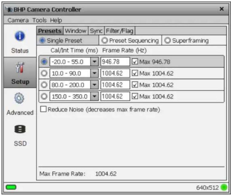
TIP: The controller often provides additional information using tooltips. Mouse over just about any control or indicator to see information about the current setting or about the bounds of valid values for the control.

flowchart
graph LR
    A["Frame Sync"] --> B["Preset 0 Integration"]
    B --> C["Preset 0 Integration"]
    C --> D["Preset 0 Integration"]
    D --> E["Preset 0 Integration"]
    E --> F["Preset 0 Integration"]
    F --> G["Preset 0 Integration"]
    G --> H["Preset 0 Integration"]
    H --> I["Preset 0 Integration"]
    I --> J["Preset 0 Integration"]
    J --> K["Preset 0 Integration"]
    K --> L["Preset 0 Integration"]
    L --> M["Preset 0 Integration"]
    M --> N["Preset 0 Integration"]
    N --> O["Preset 0 Integration"]
    O --> P["Preset 0 Integration"]
    P --> Q["Preset 0 Integration"]
    Q --> R["Preset 0 Integration"]
    R --> S["Preset 0 Integration"]
    S --> T["Preset 0 Integration"]
    T --> U["Preset 0 Integration"]
    U --> V["Preset 0 Integration"]
    V --> W["Preset 0 Integration"]
    W --> X["Preset 0 Integration"]
    X --> Y["Preset 0 Integration"]
    Y --> Z["Preset 0 Integration"]
    Z --> AA["Preset 0 Integration"]
    AA --> AB["Preset 0 Integration"]
    AB --> AC["Preset 0 Integration"]
    AC --> AD["Preset 0 Integration"]
    AD --> AE["Preset 0 Integration"]
    AE --> AF["Preset 0 Integration"]
    AF --> AG["Preset 0 Integration"]
    AG --> AH["Preset 0 Integration"]
    AH --> AI["Preset 0 Integration"]
    AI --> AJ["Preset 0 Integration"]
    AJ --> AK["Preset 0 Integration"]
    AK --> AL["Preset 0 Integration"]
    AL --> AM["Preset 0 Integration"]
    AM --> AN["Preset 0 Integration"]
    AN --> AO["Preset 0 Integration"]
    AO --> AP["Preset 0 Integration"]
    AP --> AQ["Preset 0 Integration"]
    AQ --> AR["Preset 0 Integration"]
    AR --> AS["Preset 0 Integration"]
    AS --> AT["Preset 0 Integration"]
    AT --> AU["Preset 0 Integration"]
    AU --> AV["Preset 0 Integration"]
    AV --> AW["Preset 0 Integration"]
    AW --> AX["Preset 0 Integration"]
    AX --> AY["Preset 0 Integration"]
Single Preset Mode
5.4.2.1.2 Preset Sequencing Mode
In preset sequencing mode, the camera will cycle through each preset on a frame-by-frame basis. Clicking the Preset Sequencing radio button changes the controller display and puts the camera in Preset Sequencing mode. The controller displays the current sequence configuration.
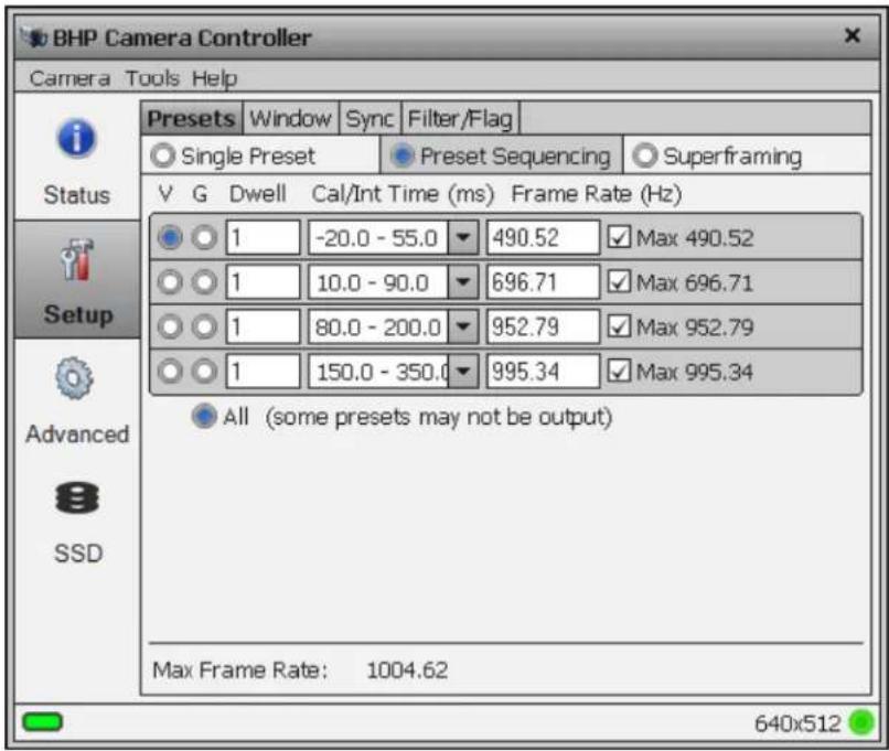
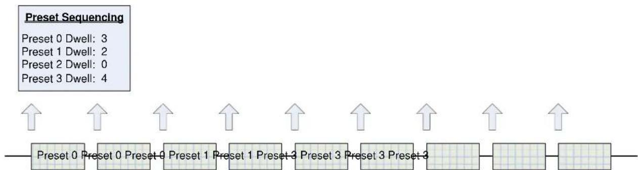
The camera will stay at each preset for a number of frames set in the Dwell column. This setting is the dwell time (in frames) for each preset. A dwell time of zero tells the camera to skip that preset and proceed to the next non-zero preset. For example:
flowchart
graph LR
    A["Preset 0"] --> B["Preset 1"]
    B --> C["Preset 2"]
    C --> D["Preset 3"]
    D --> E["..."]
    E --> F["Preset 3 Preset 3"]
    F --> G["Preset 3 Preset 3"]
    G --> H["Preset 3 Preset 3"]
    H --> I["Preset 3 Preset 3"]
    I --> J["Preset 3 Preset 3"]
    J --> K["Preset 3 Preset 3"]
    K --> L["Preset 3 Preset 3"]
    L --> M["Preset 3 Preset 3"]
    M --> N["Preset 3 Preset 3"]
    N --> O["Preset 3 Preset 3"]
    O --> P["Preset 3 Preset 3"]
    P --> Q["Preset 3 Preset 3"]
    Q --> R["Preset 3 Preset 3"]
    R --> S["Preset 3 Preset 3"]
    S --> T["Preset 3 Preset 3"]
    T --> U["Preset 3 Preset 3"]
    U --> V["Preset 3 Preset 3"]
    V --> W["Preset 3 Preset 3"]
    W --> X["Preset 3 Preset 3"]
    X --> Y["Preset 3 Preset 3"]
    Y --> Z["Preset 3 Preset 3"]
    Z --> AA["Preset 3 Preset 3"]
    AA --> AB["Preset 3 Preset 3"]
    AB --> AC["Preset 3 Preset 3"]
    AC --> AD["Preset 3 Preset 3"]
    AD --> AE["Preset 3 Preset 3"]
    AE --> AF["Preset 3 Preset 3"]
    AF --> AG["Preset 3 Preset 3"]
    AG --> AH["Preset 3 Preset 3"]
    AH --> AI["Preset 3 Preset 3"]
    AI --> AJ["Preset 3 Preset 3"]
    AJ --> AK["Preset 3 Preset 3"]
    AK --> AL["Preset 3 Preset 3"]
    AL --> AM["Preset 3 Preset 3"]
    AM --> AN["Preset 3 Preset 3"]
    AN --> AO["Preset 3 Preset 3"]
    AO --> AP["Preset 3 Preset 3"]
    AP --> AQ["Preset 3 Preset 3"]
    AQ --> AR["Preset 3 Preset 3"]
    AR --> AS["Preset 3 Preset 3"]
    AS --> AT["Preset 3 Preset 3"]
    AT --> AU["Preset 3 Preset 3"]
    AU --> AV["Preset 3 Preset 3"]
    AV --> AW["Preset 3 Preset 3"]
    AW --> AX["Preset 3 Preset 3"]
    AX --> AY["Preset 0 Dwell: 0,1,2,3,4 Dwell: 0,2,3,4 Dwell: ..."]
Preset Sequencing
The main purpose of preset sequencing is to capture a large dynamic range event with various integration times. Consider a rocket launch as an example. During the launch a short integration time would be needed to monitor the plume of the rocket. However, such a short integration time would not yield adequate images across the rest of the rocket body. If the integration time were increased to yield adequate images across the entire rocket, the rocket plume would saturate the detector. Preset sequencing cycles through up to four different integration periods.
The radio button next to the Dwell field tells the camera which preset to send to the active video output.
Optimized vs. Traditional Preset Sequencing
In traditional Preset Sequencing you can only adjust integration time and dwell for each preset. The X-series incorporates Optimized Preset Sequencing. This allows the user to set integration time, dwell, and frame rate for each preset. This is depicted in the diagram below.
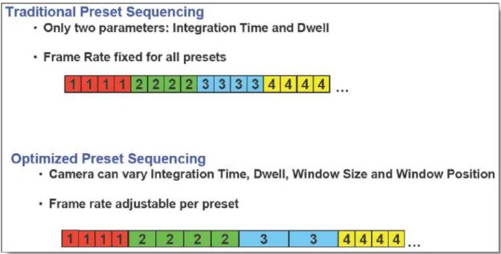
NOTE: Optimized Preset Sequencing is only available when using internal frame sync. Traditional Preset Sequencing is used in external sync mode. To achieve the fastest possible frame rates, the camera must be in Frame Sync Starts Readout (FSSR) mode. If the camera is in Frame Sync Starts Integration (FSSI) mode, the camera will be limited to ITR frame rate timing. See Section 5.4.2 for more details.
5.4.2.1.3 Superframing Mode
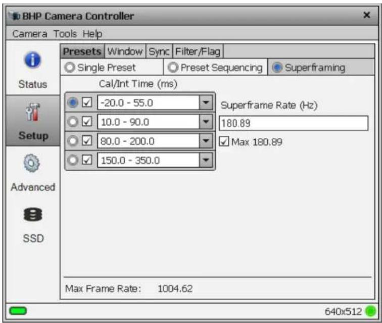
Superframing is a subset of preset sequencing with dwell counts of 0 (unchecked) or 1 (checked) and optimized frame rates for each preset. The user enables the checkbox for each preset they wish to include in the Superframing. The “superframe rate” is the rate at which the entire group of included presets is generated. The radio buttons to the left of the checkboxes select which preset will be displayed on the active video output.
Optimized vs. Traditional Superframing:
In traditional Superframing, the time between subframes is dictated by the longest integration time. In addition, the superframe rate cannot be set independently of the subframe rate. This typically forces a user to run the camera at the fastest frame rate in order to minimize the time between subframes. This may force the user to collect much more data than is actually necessary. With Optimized Superframing, the time between subframes is set by the minimum readout time. This allows the subframes to be packed together as closely as possible. The user sets the superframe rate. This sets the time between bursts of superframes. The end result is that with Optimized Superframing the user can achieve fast subframe rates to minimize registration error when “abating” the images while using a slower superframe rate to minimize data storage requirements. This is depicted in the diagram below.
Traditional Superframing
- Time between subframes set by longest integration time

flowchart
graph LR
    A["Frame Sync"] --> B["Int n"]
    B --> C["Data Xfer Frame n-1"]
    C --> D["Int n+1"]
    D --> E["Data Xfer Frame n-1"]
    E --> F["Int n+2"]
    F --> G["Data Xfer Frame n-1"]
    G --> H["Int n+3"]
    H --> I["Data Xfer Frame n-1"]
    I --> J["Int n+4"]
    J --> K["Frame Sync"]
    style A fill:#f9f,stroke:#333
    style K fill:#f9f,stroke:#333
- Superframe rate cannot be set independently from the subframe rate

Optimized Superframing
• Time between subframes set by minimum readout time

flowchart
graph LR
    A["Frame Sync"] --> B["Int n"]
    B --> C["Data Xfer"]
    C --> D["Frame n-1"]
    D --> E["Frame Sync"]
    E --> F["Int n+1"]
    F --> G["Data Xfer"]
    G --> H["Frame n-1"]
    H --> I["Frame Sync"]
    I --> J["Int n+2"]
    J --> K["Data Xfer"]
    K --> L["Frame n-1"]
    L --> M["Frame Sync"]
    M --> N["Int n+3"]
    N --> O["Data Xfer"]
    O --> P["Frame n-1"]
    P --> Q["Frame Sync"]
    Q --> R["Int n+4"]
• Superframe rate independent of subframe rate

NOTE: Optimized Superframing is only available when using internal frame sync. Traditional Superframing is supported in external sync mode. To achieve the fastest possible frame rates, the camera must be in Frame Sync Starts Readout (FSSR) mode. If the camera is in Frame Sync Starts Integration (FSSI) mode, the camera will be limited to ITR frame rate timing. See Section 5.4.2 for more details.
5.4.2.2 Window Tab
The Window tab allows the user to set the size of the active image window and the location of the window. The window size and offset for the image data must be the same for both the FPA and analog video. The Window Tab contains two sub-tabs: FPA and Analog Video.
5.4.2.2.1 FPA Sub-tab
The window height, width, and offsets can be set to any desired value, within the limits of each ROIC type. The range of valid values for each field can be seen in a tooltip by moving the mouse over the field.
The FPA Window settings can be changed by either entering values in the appropriate fields or by dragging the handles on the window indicator (green shaded box). Use the handles to set the window size and then drag the whole box to set the location. The window settings will turn red if a value has been changed but not applied. A yellow value indicates an invalid value has been chosen.
Click the Apply button to update the camera. The fields will turn gray when the changes have been accepted.
Use the Invert/Revert check boxes to flip the image vertically (Invert) or horizontally (Revert). This is useful if your optics cause the image to be flipped. This flipping is done on the FPA itself and a new NUC is typically required if these settings are changed.
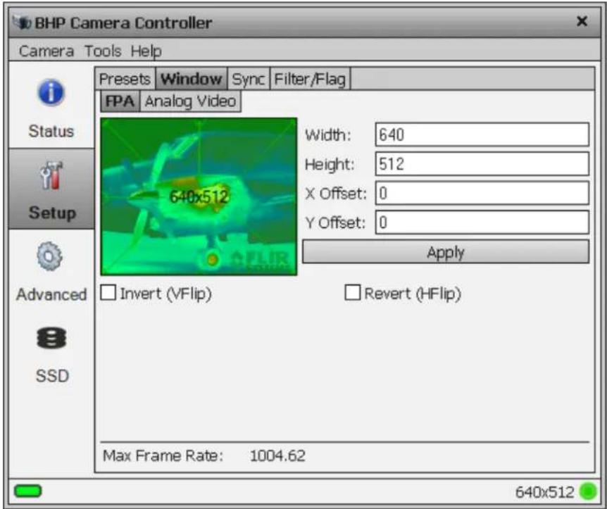
X6800/X6900 Frame Size Variables
| Minimum | Maximum | Step Size | |
| Frame Width | 32 | 640 | 32 pixels |
| Frame Height | 4 | 512 | 4 pixels |
| Horizontal Offset | 0 | Depends on window size | 4 pixels |
| Vertical Offset | 0 | Depends on window size | 4 pixels |
X8500 Frame Size Variables
| Minimum | Maximum | Step Size | |
| Frame Width | 64 | 1280 | 32 pixels |
| Frame Height | 4 | 1024 | 4 pixels |
| Horizontal Offset | 0 | Depends on window size | 4 pixels |
| Vertical Offset | 0 | Depends on window size | 4 pixels |
NOTE: Windowing in the horizontal direction will not affect frame rate.
5.4.2.2.2 Analog Video sub-tab
The analog video outputs always put out a standard size video frame. If the camera FPA image is windowed down in size, then there will be black areas in the Analog Video. The Analog Video sub tab allows the user to control how the FPA digital image data is positioned within the analog video frame.
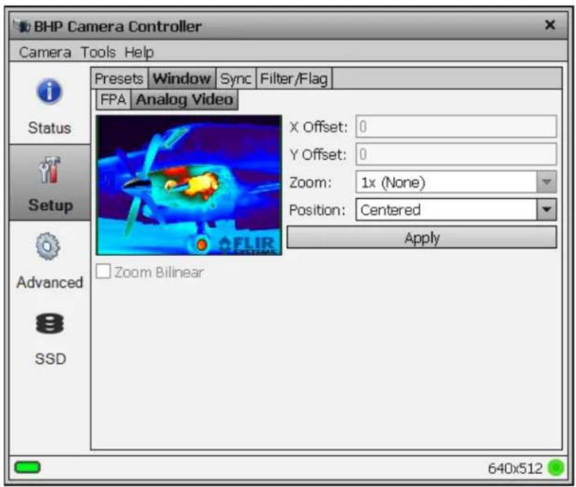
| Zoom Modes | |
| Zoom | Because video modes have a fixed frame size, adjusting the FPA window size can cause large empty areas around the image in the video. The video zoom feature can reduce this effect by applying a digital zoom factor to the image. The available zooms are: x12 , x1 , x2 , x4/3 , x4 . (4/3 zoom is good for displaying a 640x512 image on a 720p display. |
| Analog Video Position Modes | |
| Centered | FPA data is placed in center of analog frame |
| Same as FPA | Uses Offsets from FPA sub-tab |
| Offset | Uses X & Y offsets on this page to locate upper left corner of image data in the video frame |
5.4.2.3 Sync Tab
The Sync Tab allows the user to set the FPA sync mode, and sync/trigger options. At this point it is helpful to define some terms. A sync is a signal that synchronizes the timing of an individual frame. A trigger is a signal that synchronizes the start of a sequence of frames. The X-series has independent SYNC and TRIGGER inputs. The SYNC and TRIGGER IN input require a 3.3V TTL pulse (5V max).
5.4.2.3.1 Sync Mode
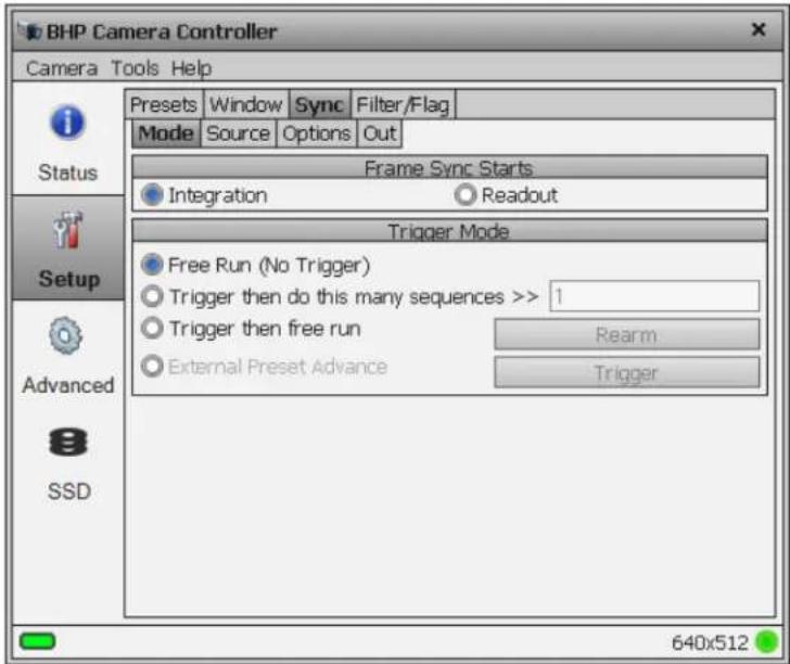
The X-series makes use of frame syncs and triggers to control the generation of image data. Again, frame syncs control the start of individual frames whereas triggers start sequences of frames.
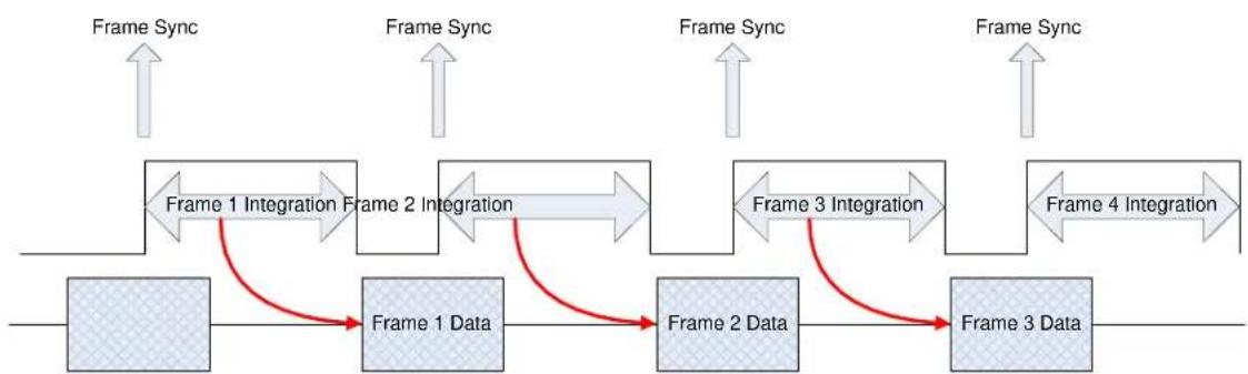
The generation of a frame consists of two phases: integration and data readout. Depending on the timing between these two events, you can have two basic integration modes: Integrate Then Read (ITR) and Integrate While Read (IWR). In ITR, integration and data readout occur sequentially. The complete frame time is the combined total of the integration time plus readout time. In IWR, the integration phase of the current frame occurs during the readout phase of the previous frame. In other words, ITR and IWR terms refer to whether or not the camera will overlap the data readout and integration periods. In ITR, the data is not overlapped which means lower frame rates but provides a less noisy image. IWR can achieve much faster frame rates with a slight increase in noise. The X-series does not require the user to explicitly choose whether to operate in ITR or IWR modes. The camera will automatically select the integration mode based on the integration time, frame rate, and frame sync mode.
The X-series supports two Frame Sync Modes: Frame Sync Starts Integration (FSSI), and Frame Sync Starts Readout (FSSR). FSSI and FSSR determine which phase of the frame generation process (integration or data readout) is synchronized to the frame sync. FSSI starts the integration period when a frame sync occurs (i.e. “take a picture now”). The camera automatically calculates when to start data readout. FSSR starts the data readout (for the previous frame) when a frame sync occurs (i.e. “give me data now”). The camera automatically calculates when to start integration for the current frame. In FSSI mode, the camera could be in either ITR or IWR mode. In FSSR mode, the camera is always in IWR mode.
5.4.2.3.1.1.1 Frame Sync Starts Integration (FSSI)
Upon frame sync, the camera immediately integrates followed by data read out. Based on integration time, frame size, and frame rate, the camera will automatically choose ITR or IWR mode.
NOTE: When using an external frame sync and preset sequencing or superframing, the external frame sync should be set to comply with ITR frame rate limits. If the external sync rate is too fast, the camera will ignore syncs that come before the camera is ready

flowchart
graph LR
    A["Frame Sync"] --> B["Preset 0 Integration"]
    B --> C["Preset 1 Integration"]
    C --> D["Preset 2 Integration"]
    D --> E["Preset 3 Integration"]
    E --> F["Preset 3 Data"]
    B <--> C
    C <--> D
    D <--> E
    style A fill:#f9f,stroke:#333
    style B fill:#ccf,stroke:#333
    style C fill:#ccf,stroke:#333
    style D fill:#ccf,stroke:#333
    style E fill:#ccf,stroke:#333
    style F fill:#cfc,stroke:#333
Frame Sync Starts Integration, ITR
flowchart
graph LR
    A["Frame Sync"] --> B["Frame 1 Integration"]
    B --> C["Frame 2 Integration"]
    C --> D["Frame 3 Integration"]
    D --> E["Frame 4 Integration"]
    E --> F["Frame 3 Data"]
    F --> G["Frame 2 Data"]
    G --> H["Frame 1 Data"]
    H --> I["Frame 1 Integration"]
    I --> J["Frame Sync"]
    style A fill:#f9f,stroke:#333
    style B fill:#ccf,stroke:#333
    style C fill:#ccf,stroke:#333
    style D fill:#ccf,stroke:#333
    style E fill:#ccf,stroke:#333
    style F fill:#ccf,stroke:#333
    style G fill:#ccf,stroke:#333
    style H fill:#ccf,stroke:#333
    style I fill:#ccf,stroke:#333
Frame Sync Starts Integration, IWR
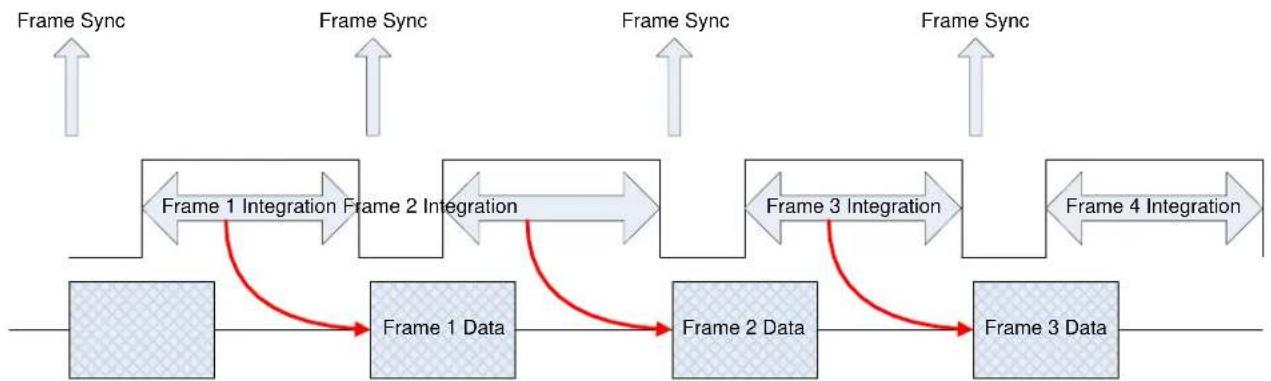
Upon frame sync, the camera immediately transmits the data from the previous frame. The integration period is then placed to meet ROIC requirements. This mode always operates in IWR mode. This mode can be used with either internal or external frame sync at full frame rates.
flowchart
graph LR
    A["Frame Sync"] --> B["Frame 1 Integration"]
    B --> C["Frame 2 Integration"]
    C --> D["Frame 3 Integration"]
    D --> E["Frame 4 Integration"]
    E --> F["Frame 3 Data"]
    F --> G["Frame 2 Data"]
    G --> H["Frame 1 Data"]
    H --> I["Frame 1 Integration"]
    I --> J["Frame Sync"]
    style A fill:#f9f,stroke:#333
    style B fill:#ccf,stroke:#333
    style C fill:#ccf,stroke:#333
    style D fill:#ccf,stroke:#333
    style E fill:#ccf,stroke:#333
    style F fill:#ccf,stroke:#333
    style G fill:#ccf,stroke:#333
    style H fill:#ccf,stroke:#333
    style I fill:#ccf,stroke:#333
Frame Sync Starts Readout
A sequence consists of a series of frames. In Preset Sequencing, that series of frames can be any number of any of the four presets. In Superframing, the series is one or zero frames from each preset. In Single Preset, the series is simply one frame of the selected preset.
When a trigger occurs, the camera will complete a sequence a set number of times. For example, if Preset Sequencing is used with a dwell of two frames set for all four presets, each trigger would generate 8 frames. If the user set the camera to complete 3 sequences upon triggering, the camera would generate 24 frames.
| Trigger Modes | |
| Free Run | In free run the camera cycles through frames/sequences continuously. |
| Trigger, then do this many sequences | Upon receiving a trigger (external or software), the camera generates the number of sequences entered in the box (max limit: >4x10⁹). |
| Trigger then free run | Upon receiving a trigger (external or software) the camera will start to generate sequences continuously. |
| External Preset Advance | Upon receiving a trigger (external or software) the camera will advance to the next preset with a non-zero dwell setting. |

flowchart
graph LR
    A["Trigger"] --> B["nSequences = 3"]
    B --> C["Preset 0 Preset 1 Preset 2 Preset 3"]
    C --> D["Preset 0 Preset 1 Preset 2 Preset 3"]
    D --> E["Preset 0 Preset 1 Preset 2 Preset 3"]
    E --> F["..."]
    F --> G["..."]
    G --> H["..."]
ITR Frame Process
The Source options page allows the user to select the source for Syncs and Triggers.
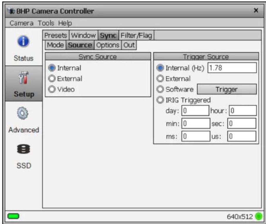
| Sync Sources | |
| Internal | The frame sync is generated internally to run at the frequency set by the user |
| External | The frame sync is generated externally through the Sync In connect on the camera rear chassis. |
| Video | The frame sync is generated from an external video source connected to the Gen Lock In connector on the camera rear chassis. |
| Trigger Sources | |
| Internal | The trigger is generated internally to run at the frequency set by the user (Hz). |
| External | The trigger is generated externally through the Trigger In connector on the camera rear chassis. (3.3V TTL) |
| Software | The trigger is generated via a software button (Trigger button) |
| IRIG Triggered | Camera generates an internal trigger when the internal IRIGclock reaches a specified time. |
5.4.2.3.3 Sync Options
The Sync Options page allows the user to set delays and polarities for the Sync and Trigger In.
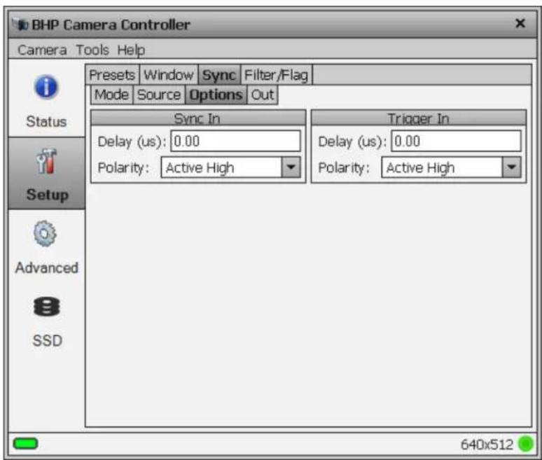
| Sync In | |
| Delay | Allows for the user to set a delay (μsec) for the external sync. See timing diagrams below. |
| Polarity | The sync is edge triggered. This allows for the camera to use either the rising or falling edge. |
| Trigger In | |
| Delay | Allows for the user to set a delay (μsec) for the external trigger. See timing diagrams below. |
| Polarity | The trigger is edge triggered. This allows for the camera to use either the rising or falling edge. |
NOTE: The camera has a latency of approximately 1 microsecond when responding to a sync or trigger signal.
5.4.2.3.4 Sync Out
The Sync Out options allow the user to set a delay for the sync out pulse as well as the sync delay reference and polarity. The Sync Out signal always has a jitter of ±1 clock (160nsec).
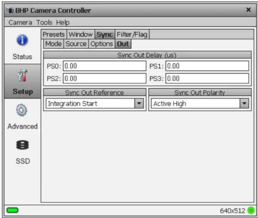
| Sync Out Options | |
| Sync Out Delay | Allows for the user to set a delay (in microseconds) for the sync out on a preset basis. |
| Sync Out Source | Allows for the sync out to be referenced to the start of frame or start of integration. |
| Sync Out Polarity | Allows for the sync out to be active high or low. |
5.4.2.4 Filter/Flag
The Filter/Flag page controls the internal NUC flag and warm filter wheel.
5.4.2.4.1 Flag controls
Normally the NUC flag is primarily used with the Auto NUC function. However, it can be manually controlled from this page.
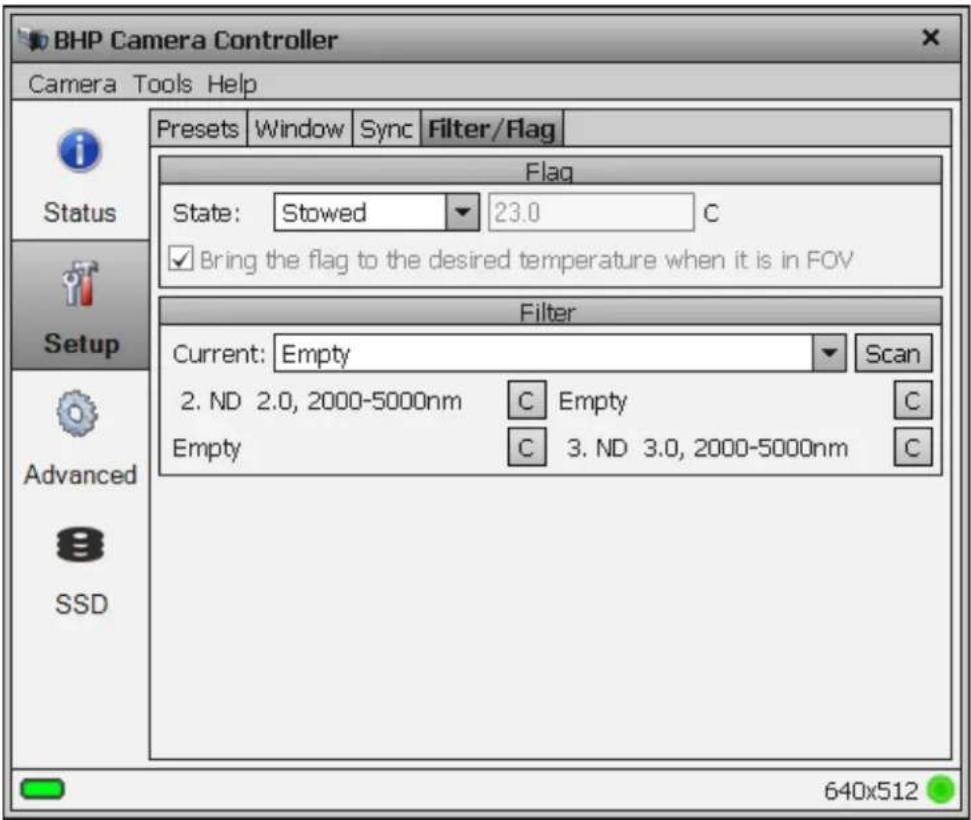
| Flag Controls | |
| State | Stowed: Flag not in field of viewDeployed: Flag in field of view |
| Temperature | The standard NUC flag does not have a temperature control, so this field and the checkbox will be grayed out. Cameras that do not have the filter wheel have a NUC flag with a TEC cooler. The temperature of the flag can be set from this page. |
5.4.2.4.2 Filter Wheel Controls
The X-series has a motorized 4-position filter wheel. Warm filters are held in the wheel by a removable filter holder. Each holder can hold up to two filters with a combined thickness of 2mm. The holders have an ID number that is encoded using a set of magnets. The camera can recognize the ID number. The camera can also store a text description for the filter ID. The Current filter drop down list shows the filters currently in the wheel. Selecting an item from the list will tell the camera to move that filter into the field of view. Below the filter selector is a list of filters detected by the camera. If you wish to replace a filter, click the "C" button. This will move that filter into the field of view so that
it can be accessed. See Section 7 for more information on how to install filters. After installing a filter, press the "Scan" button so that the camera can detect the new filter IDs.
5.4.3 Advanced Page
The Advanced Page contains controls for performing and managing on-camera Non-Uniformity Corrections (NUCs), Analog video AGC, analog and digital offset, detector bias and a few advanced miscellaneous features.
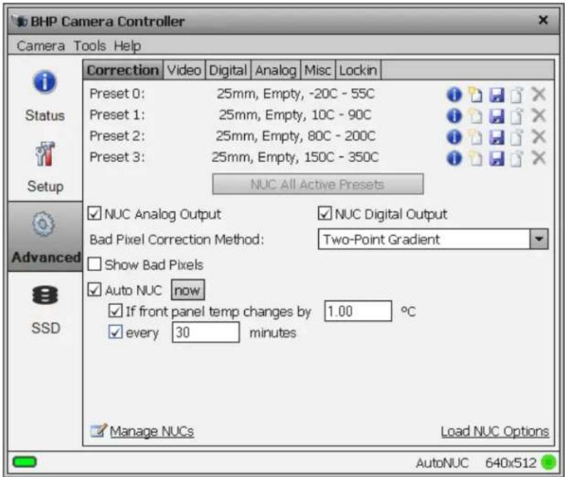
5.4.3.1 Non-Uniformity Correction (NUC)
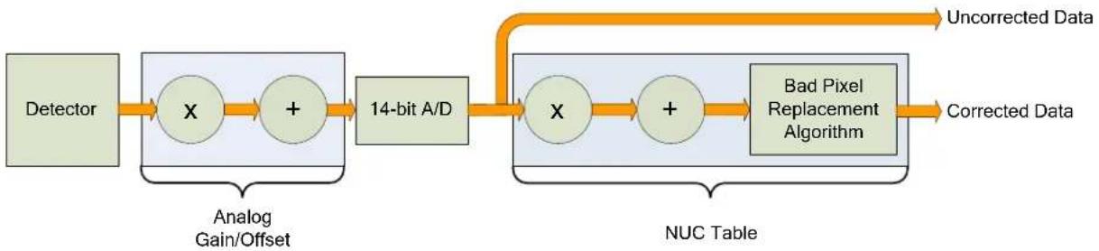
Non-Uniformity Correction (NUC) refers the process by which the camera electronics correct for the differences in the pixel-to-pixel response for each individual pixel in the detector array. The camera can create (or allow for the user to load) a Non-Uniformity Correction (NUC) table which consists of a unique gain and offset coefficient and a bad pixel indicator for each pixel. The table is then applied in the digital processing pipeline as shown below. The result is corrected data where each pixel responds consistently across the detector input range creating a uniform image.
flowchart
graph LR
    A["Detector"] --> B["X"]
    B --> C["+"]
    C --> D["14-bit A/D"]
    D --> E["X"]
    E --> F["+"]
    F --> G["Bad Pixel Replacement Algorithm"]
    G --> H["Corrected Data"]
    I["Analog Gain/Offset"] --> B
    J["NUC Table"] --> E
    K["Uncorrected Data"] --> G
Digital Process Showing NUC Table Application
To create the NUC table, the camera images either one or two uniform temperature sources. The source can be an external source provided by the user or the camera's internal NUC flag which is basically a shutter the camera places in front of the detector. If the source is external it should be uniform and large enough to overfill the cameras field-of-view (FOV). By analyzing the pixel data from these constant sources, the non-uniformity of the pixels can be determined and corrected. There are three types of processes which are used to create the NUC table; One-Point, Two-Point, and Offset Update.
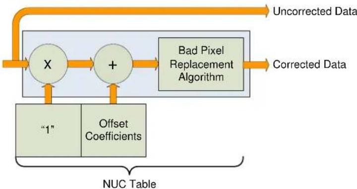
5.4.3.1.1 One-Point Correction Process
A One-Point Correction Process requires one uniform source, which is typically in the middle of the usable range. The One-Point Correction replaces all gain coefficients in the NUC table with a value of one ("1") as seen in the figure below. The offset coefficients are computed uniquely for each pixel.
flowchart
graph TD
    A["Uncorrected Data"] --> B["X"]
    C["Corrected Data"] --> D["+"]
    B --> D
    D --> E["Bad Pixel Replacement Algorithm"]
    F["1"] --> B
    G["Offset Coefficients"] --> D
    H["NUC Table"] --> B
    H --> D
One-Point Correction
5.4.3.1.2 Two-Point Correction Process
The Two-Point Correction Process builds a NUC table that contains an individually computed gain and offset coefficient for each pixel as seen in the figure below. Two uniform sources are required for this correction. One source at the low end and a second source at the upper end of the usable detector input range. Because of the use of two images at either end of the input range, the Two-Point Correction yields better correction results verses the One-Point process. A 2-point correct will also work better over a wider range of scene temperatures than a 1-point correction.
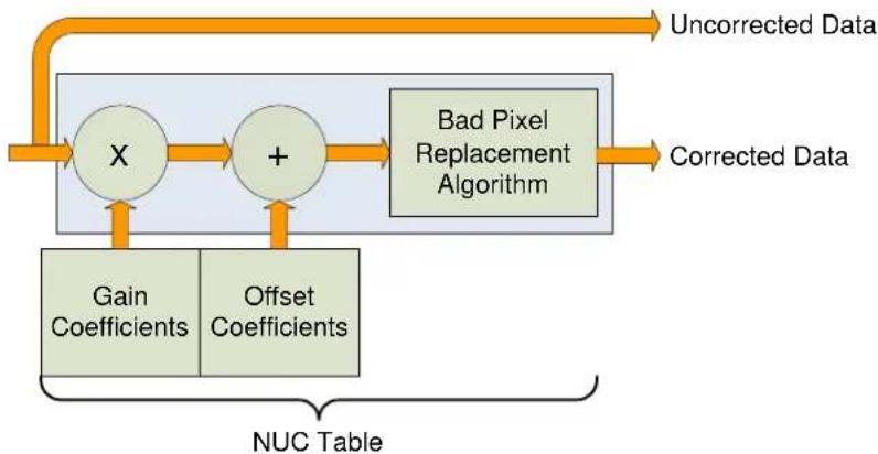
flowchart
graph TD
    A["Uncorrected Data"] --> B["X"]
    B --> C["+"]
    C --> D["Bad Pixel Replacement Algorithm"]
    D --> E["Corrected Data"]
    F["Gain Coefficients"] --> B
    G["Offset Coefficients"] --> C
    H["NUC Table"] --> F
    H --> G
Two-Point Correction
5.4.3.1.3 Update Offset
Often times during the normal operation of a camera the electronics and/or optics will heat up or cool down which changes the uniformity of the camera image. This change requires a new NUC. However, this change is mainly in the offset response of the image while the gain component stays constant. An Update Offset simply computes a new offset coefficient using the existing gain coefficient and corrects the image non-uniformity. Update Offsets are typically performed when a Two-Point NUC table is being used.
An Update Offset requires only one uniform source, usually set at a temperature on the lower edge of the operational range.
5.4.3.1.4 Bad Pixel Correction
Within the NUC table there is an indication as to whether or not a pixel has been determined to be bad as shown below. There are two methods used to determine bad pixels.
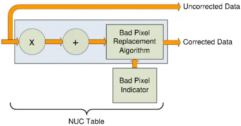
flowchart
graph TD
    A["Uncorrected Data"] --> B["X"]
    B --> C["+"]
    C --> D["Bad Pixel Replacement Algorithm"]
    D --> E["Corrected Data"]
    F["Bad Pixel Indicator"] --> D
    G["NUC Table"] --> H
Bad Pixel Correction
First, the NUC table gain coefficients are compared to a user defined acceptance boundary, Responsivity Limit Low/High (%). The responsivity of a pixel can be thought of as the gain of that pixel. The gain coefficient in the NUC Table is a computed value that attempts to correct the individual pixel gain, or responsivity, to a normalized value across the array. Since the responsivity value directly relates to the gain coefficient in the NUC table, the camera can scan the NUC table gain coefficients and use them to determine if a pixel's responsivity exceeds the limits as set by the user.
The second method of determining bad pixels is to search for twinklers. Twinklers are pixels that have responsivity values within normal tolerances, but still exhibit large swings for small input changes. These pixels are on the “verge” of being bad and often appear to be noisy. To find these types of pixels the camera collects a number of frames and records the maximum and minimum values across that sample set for each pixel. If the delta between max and min exceeds the Twinkler max pixel value delta then the pixel is determined to be bad.
Since the responsivity test requires a gain coefficient, it is useless on NUC tables determine by the One-Point Correction because those tables have a value of one ("1") as the gain coefficients. The Twinkler test can be done on either correction process.
The X-series camera uses the Nearest Neighbor algorithm for bad pixel replacement, a simple replacement using an adjacent pixel. The adjacent pixel is picked using the pattern depicted below. When a bad pixel is near an edge, those search positions are skipped.
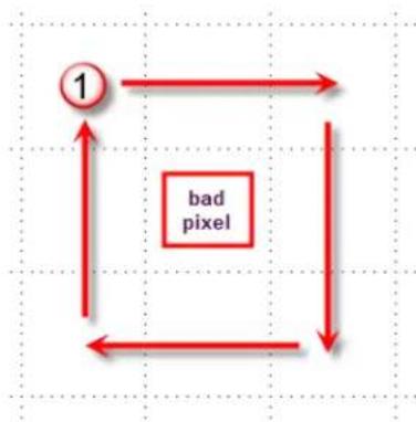
flowchart
graph TD
    A["1"] --> B
    B --> C
    C --> D
    D --> A
    style A fill:#fff,stroke:#000
    style B fill:#fff,stroke:#000
    style C fill:#fff,stroke:#000
    style D fill:#fff,stroke:#000
    note right of C "bad pixel"
5.4.3.2 Correction Tab
The Correction Tab contains all the controls needed to manage the on-camera NUCs. On-camera NUCs are stored in two types of memory:
RAM memory. This type of memory is used to store NUCs that will be applied to live image data. There is enough RAM memory for one NUC to be loaded for each Preset. This memory is volatile and is lost when then camera is turned off. If a NUC was loaded into RAM, the camera will reload that NUC from flash automatically when the camera is turned on if a Save State was performed.
Flash Memory. This type of memory is used as nonvolatile NUC storage. There is about 2GB of flash memory available for storing NUCs. This is enough space to store >400 full frame NUCs.
| NUC Controls | |
 | NUC Info. Displays camera parameters and statistics related to the selected NUC |
 | Perform NUC. Starts the NUC Wizard. |
 | Updates the current NUC to flash memory |
 | Load a NUC from flash to RAM memory. |
| [SHZ4] | Unload NUC from RAM memory. No on-camera NUC will be applied to the data. |
| ☑ NUC Analog Output | Apply NUC to video data. “Analog” is a legacy description This checkbox applies to all video outputs. |
| ☑ NUC Digital Output | Apply NUC to Digital output (GigE, Camera Link) |
| ☐ Show Bad Pixels | Displays all pixels marked as “bad” as white dots on both the analog and digital outputs. |
| ☐ Auto NUC | When enabled, the camera will automatically drop the internal flag and perform a NUC Offset Update when selected criteria are met. The NUC update can be triggered on demand, by a change in the internal temperature sensor or by a timer |
| ☑ Manage NUCs | Displays a list of NUCs stored in flash memory. User ca delete NUCs from flash memory as well as upload/download NUCs (.NPK files) from the host PC. |
| Load NUC Options | Displays options for loading NUCs. |
5.4.3.2.1 NUC Information
The button displays a list of camera parameters that are saved as part of the NUC as well as bad pixel statistics. Note that there is a scroll bar that can be used to see the whole list. The Save button allows the user to dump this list to a text file.
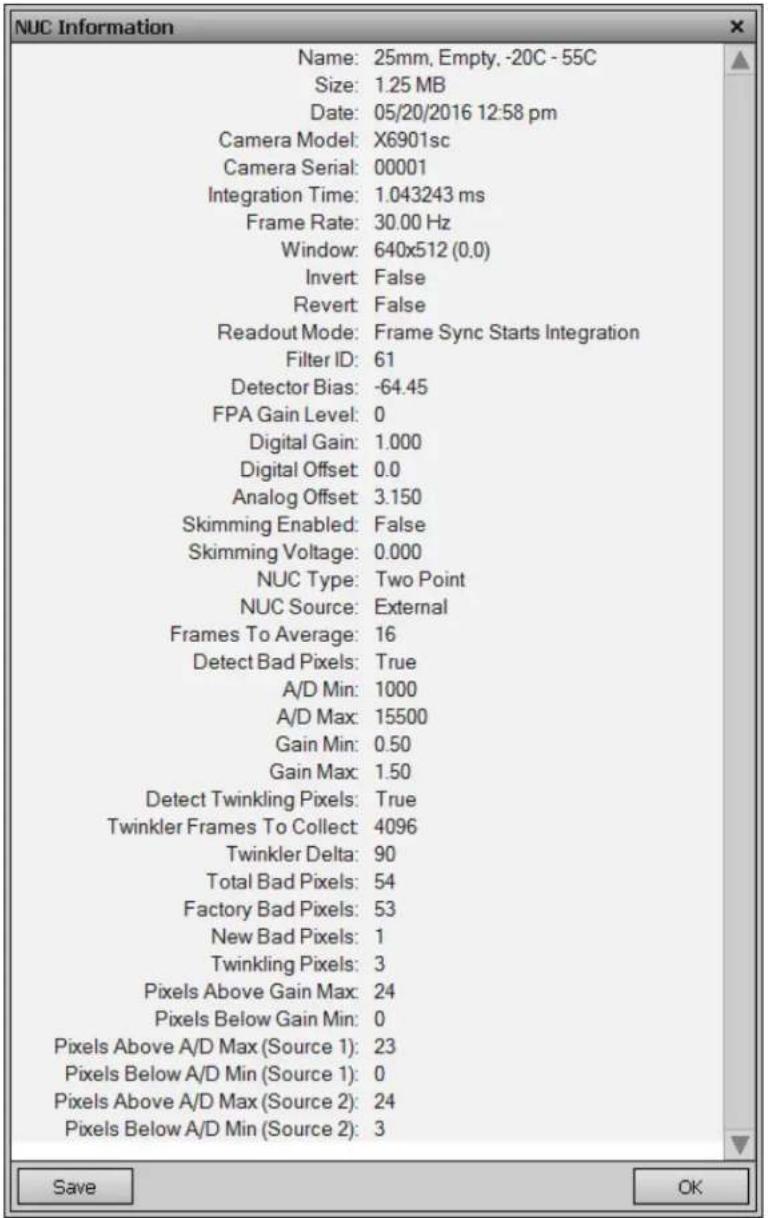
5.4.3.2.2 Load NUC Options
Typically, all of the camera configuration parameters are derived from the current Camera State. When the camera is powered up, it loads the last saved camera state. The names of the NUCs are stored as part of the state. Normally the NUC is performed with the settings that are eventually going to be part of the state. If a NUC is loaded that has a setting that differs from the camera state, the state will override the NUC. If the user wants the NUC setting to override the state, then "Load NUC Options" can be set.
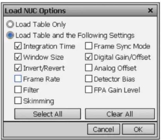
The default setting is to "Load Table Only", in which case only the NUC coefficients are used from a NUC file. When the user selects "Load Table and the Following Settings", the user can select which parameters from the NUC will override the current state. The option will not affect NUCs that are currently loaded into RAM, only those NUCs that are subsequently loaded from Flash memory. Unless a new state is saved, these override settings will not be remembered after a power cycle.
5.4.3.2.3 Performing a NUC
To create an on-camera NUC, select the Perform Correction icon to start the NUC Wizard for the desired preset. If Preset Sequencing or Superframing is enabled, the camera will only perform the NUC on the preset you select while keeping camera in the desired sequencing mode. To perform a NUC operation on all active presets at the same time, press the NUC All Active Presets button. This is convenient, for example, if you want to do an offset update to all presets with a single source.
NOTE: Due to differences in camera electronics and FPA timings it is important to perform the NUC with the camera operating modes configured as it will be used when imaging.
After selecting the Perform Correction a second window comes up to allow the user to select correction parameters. When all selections have been made, click Next>> to continue.
![BHP Camera Controller Camera Tools Help Correction Video Digital Analog Misc Lockin Status Setup Advanced SSD Correction Type One-Point Two-Point Offset Update Bad Pixel Correction Use Factory Bad Pixels Number of frames 16 Correction Source Internal Flag External Blackbody << Previous [Cancel] Next >> AutoNUC 640x512](/content/2026/05/937015/images/e6e25b64b05f4551f99d1bd8dcc531f297a94d16b18a0d8d3174886ee618395e.jpg)
| Correction (NUC) Types | |
| One Point | Sets the gain terms to “1” and computes the offset terms. Uses a single NUC source. Does not compute a BP correction. |
| Two Point | Sets both the gain and offset terms. Uses two NUC sources. Computes a bad pixel correction. |
| Offset Update | Retains the current NUC gain terms and updates the offset terms. Uses a single NUC source. Retains the current bad pixel (BP) correction. |
| Correction Sources | |
| Internal Flag | Use the internal flag as the NUC source. This is disabled for 2-point NUC because the flag is not temperature controlled |
| External Blackbody | Use an external blackbody as the NUC source. Program will prompt the user to place each source in front of the camera. NUC source needs to fill the entire field of view. |
| Number of frames | Set the number of frames to average when computing NUC coefficients. 16 is the default and works well for most scenarios. The value can be to be 2, 4, 8, 16, 32, 64, or 128. |
After configuring the correction parameters and selecting Next>> the next window allows the user to set up the parameters used for the Bad Pixel Detection. For most cases, the default values will produce a very good result. Once the parameters are set, select Next>> to continue.
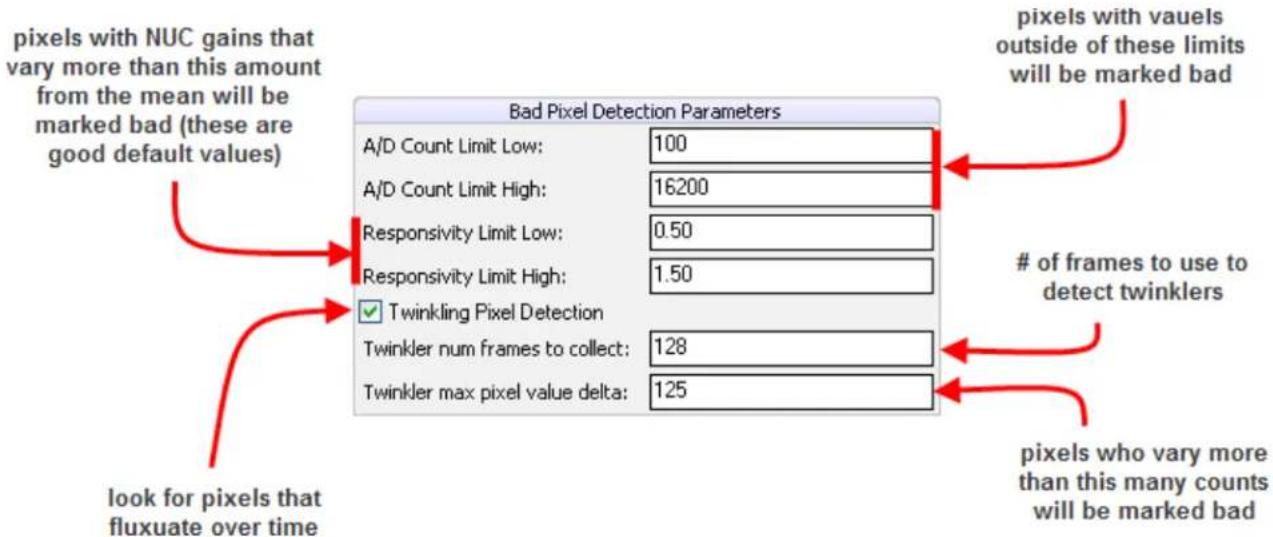
The next window allows the user to name the NUC. Simply type in the name for the table in the text box or select a previously saved file to replace it. Select Next>> to continue.
![Select NUC Name Name Window IntTime Data 8ms Factory 640x512 8.00 ms 07/21/2009 8: 0.5ms Factory 640x512 0.50 ms 07/17/2009 2: 1ms Factory 640x512 1.00 ms 07/17/2009 2: 4ms Factory 640x512 4.00 ms 07/17/2009 2: foo 512x512 8.00 ms 07/27/2009 1: List of NUCs currently stored in Flash memory Name for NUC in progress (will not be created until NUC is accepted) 8ms Factory << Previous [Cancel] Next >>](/content/2026/05/937015/images/e613105bb22f6a3f4bbbbebffbc86146e163fd01c41b43a19ec5eb64ce9cafea.jpg)
The next two screens will collect data from the NUC sources. If using the internal flag, you will only see a few status messages. If using external blackbodies, you will be prompted. After each step, click Next>> to continue.
The last screen gives a report of the bad pixels found. The dialog shows how many pixels failed in each category. If the result is satisfactory, click Accept to save the NUC. The NUC table will be stored to flash memory and loaded into RAM memory for that preset. If the NUC is poor and you want to abort, click[Discard].
![Bad Pixels Factory: 0 Twinkler: 13 At Responsivity Limit Low (%): 0 At Responsivity Limit High (%): 141 Total Bad Pixels: 154 Accept this correction? << Previous [Discard] Accept](/content/2026/05/937015/images/5513f3be187104f58d84ed88d774726a5069053df212e2a6eeea925249a9ce8a.jpg)
NOTE: It is possible for a bad pixel to fail more than one category, so the total bad pixels may be less than the sum of each category. "Factory" bad pixels are those that were determined to be bad during camera production testing.
5.4.3.3 Video Setup Tab
The X-series cameras have a 14-bit digital output. However, the video output is only 8-bit. An Automatic Gain Control (AGC) algorithm is used to map the 14-bit digital to the 8-bit analog data. The Video Tab provides controls related to optimizing the Analog video output. These controls affect only the HD/SD video. The diagram below shows a flow chart of the video process and how the parameters of this screen are used.
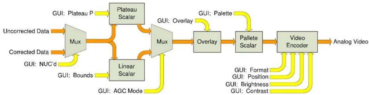
flowchart
graph LR
    A["Uncorrected Data"] --> B["Mux"]
    C["Corrected Data"] --> D["Linear Scalar"]
    E["GUI: NUC'd"] --> D
    F["GUI: Plateau P"] --> G["Plateau Scalar"]
    H["GUI: Bounds"] --> I["Linear Scalar"]
    J["GUI: AGC Mode"] --> I
    B --> K["Mux"]
    D --> K
    I --> K
    K --> L["Overlay"]
    L --> M["Pallete Scalar"]
    M --> N["Video Encoder"]
    N --> O["Analog Video"]
    style A fill:#FFD700,stroke:#333
    style C fill:#FFD700,stroke:#333
    style E fill:#FFD700,stroke:#333
    style F fill:#FFD700,stroke:#333
    style J fill:#FFD700,stroke:#333
    style N fill:#FFD700,stroke:#333
    style O fill:#FFD700,stroke:#333
Video Flow
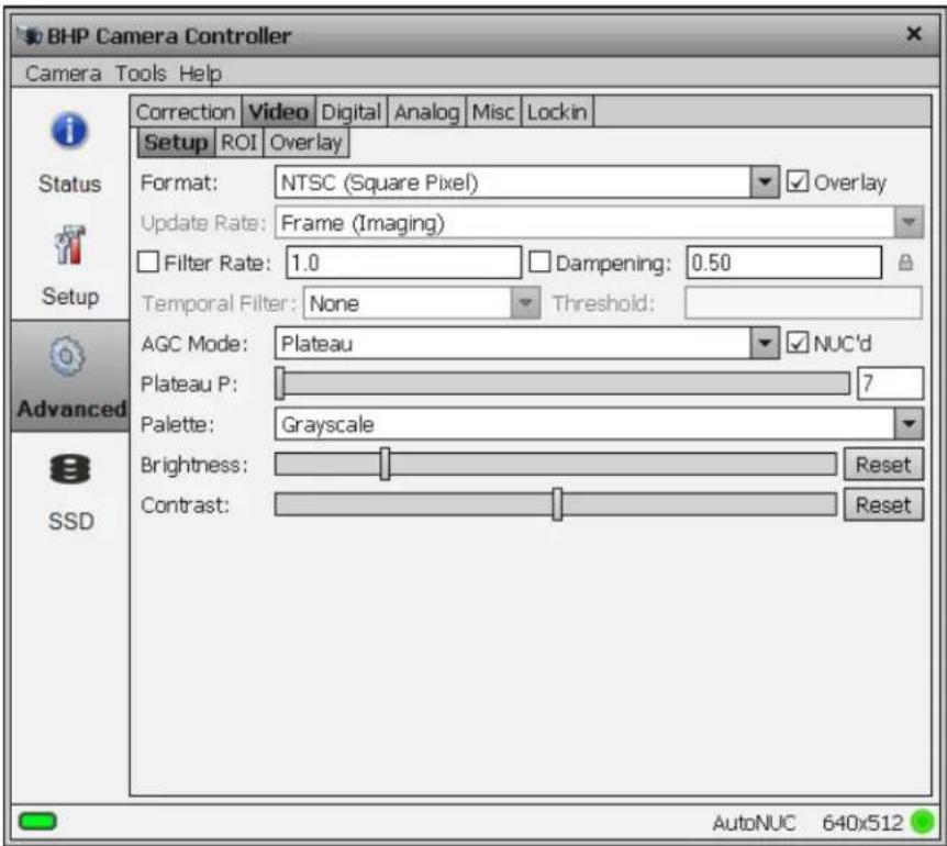
| Analog Video Setup Options | |
| Format | HDMI/SDI: 1080p @ 29.9/25Hz, 720p @ 59.9/50Hz, NTSC, PAL, |
| Overlay | Enables the video overlay. |
| Filter Rate | Rate at which AGC is computed (1 to 20 Hz). Enable with checkbox |
| Dampening | Rate at which AGC is allowed to change. This will keep the AGC from responding rapidly to fast tridents changes. Specified as a fraction from 0 to 1. This fraction is used as a weighting factor for the current AGC vs. the newly computed AGC. Setting this to 0 will “lock” the AGC to its current settings. Enable with checkbox. |
| AGC Mode | Plateau: Uses a plateau equalization (PE) algorithm to scale the image data for video displayDDE: Digital Detail Enhancement.Manual Linear: Scales the image data to a windowed section of data range as set by the userAuto Linear: Same as Manual Linear except camera analyzes image and sets limits at ~1% and 98% of the histogram. |
| Plateau P | Scaling factor for the Plateau Equalization functionNote: Plateau P is only visible when AGC Mode>>Plateau is selected |
| Bounds | Sets the lower and upper data range to be scaled to on the video data. Note: Bounds is only visible when AGC Mode>>Manual Linear is selected |
| DDE Sharpness | Only visible when AGC is set to DDE. Selects the amount of enhancement processing. |
| Palette | Allows user to select the color scheme to use on the analog video channel. |
| Brightness and Contrast | Allows user to set brightness and contrast on the video encoder. This occurs after the digital data has been scaled and converted to analog. These controls don’t tend to have as much effect as the controls that are applied to the digital side (before the video encoder). |
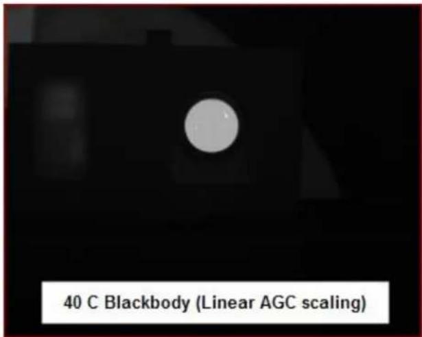
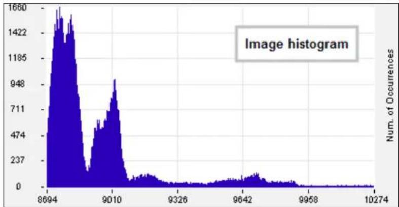
The Manual Linear algorithm evenly distributes the grayscale values over the digital values. This works fairly well if the image dynamic range is fairly evenly distributed but in general does not produce high contrast imagery, but it also does not saturate or clip the hot and cold regions either. The Plateau Equalization algorithm (also called PE) is a nonlinear AGC algorithm that uses the image histogram to optimally map the 256 gray scales. This algorithm works well for most scenes, but it works best when the scene has a “bi-modal” distribution (two clumps). It usually the most popular because algorithm because it produces high contrast (but more saturated) video. The following pictures illustrate the differences in AGC algorithms. (The data was captured from the digital output, but the effect is similar for the analog side.)
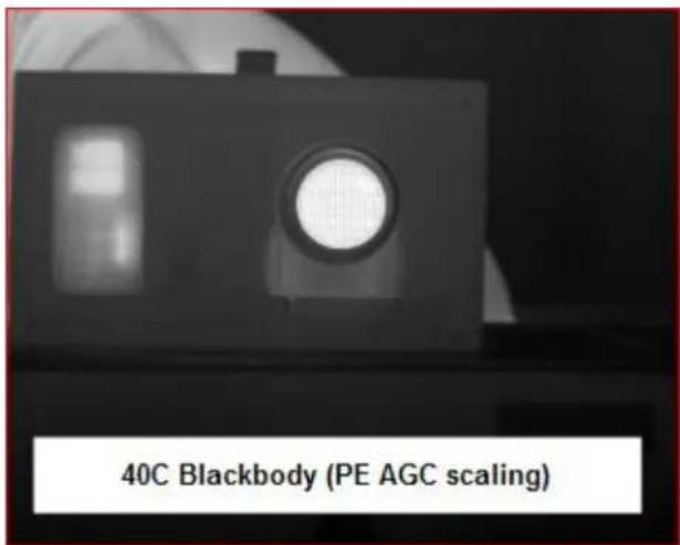
One final note about the PE algorithm: it is very aggressive. It can pull detail out of very low contrast imagery. It can also greatly enhance some very low-level NUC and FPA artifacts and noise if the contrast is low enough. This does not necessarily mean there is a problem with either the camera or the NUC.
5.4.3.4 Video ROI
The Video ROI feature allows the user to define a box region and only the pixels within the box will be used to calculate the AGC coefficients. This is particularly useful if there is part of the scene that is much higher or lower in intensity than the target of interest. The ROI is defined by entering the size and position directly in the parameter fields or the user can use the mouse to drag the corners of the green box to create the desired rectangular region.
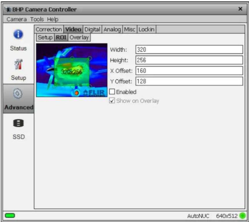
5.4.3.5 Video Overlay Tab
The X-series cameras have a video overlay feature that can display a wide variety of camera status indicators on the analog video. This lets an operator see the camera status without needing to have a PC connected. The Video Overlay tab allows the user to control which parameters are displayed and what colors are used. The position of the checkbox in the dialog box give the approximate location the object will appear in the overlay. The position of the objects cannot be adjusted in the GUI, but the SDK allow the user to completely customize the look of the overlay. Options that are grayed out are either not supported by the camera or are not enabled in another part of the GUI. (For example, Focus will be grayed out on X-series but not on the RS6700).
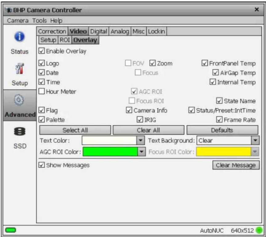
| Video Overlay Options | |
| Enable Overlay | Turns the overlay On or Off without changing the selected options |
| Logo | Displays the FLIR logo |
| Date | Displays the system date stamp |
| Time | Displays the system time stamp |
| Hour Meter | Displays the accumulated camera “on” time (H:M). (Cannot be reset by user) |
| Zoom | Display the level of Digital Zoom (x1, x2, x4), and position (C, F, O) |
| Front Panel Temp | Displays the temperature of front panel sensor in °C |
| Air Gap Temp | Displays the current temperature of air gap between front panel and internal chassis in °C |
| Internal Temp | Displays the current temperature of the internal chassis in °C |
| AGC ROI | Displays the ROI used to compute AGC values. Option is disabled if AGC ROI not enabled. |
| Flag | Displays the NUC flag status |
| Palette | Displays the current analog video palette name |
| Camera Info | Displays camera model and serial number |
| IRIG | Displays current IRIG time |
| Status/Preset | Displays sequencing mode and currently displayed preset |
| Frame Rate | Displays FPA frame rate (in single Preset mode). Displays effective rate when Preset Sequencing (PS) or Superframing (SF) |
| Select All | Selects all overlay options |
| Clear All | Deselects all overlay options |
| Defaults | Selects default overlay options (stored in current camera state) |
| Text Color | Selects overlay text color |
| Text Background | Selects overlay background color |
| AGC ROI Color | Selects AGC ROI Color |
| Show Messages | Displays special status messages |
| Clear Message | Clears current special status message display but new messages will be displayed |
5.4.3.6 Digital Tab
The Digital Tab allows the user to apply an additional gain and offset to the digital data.
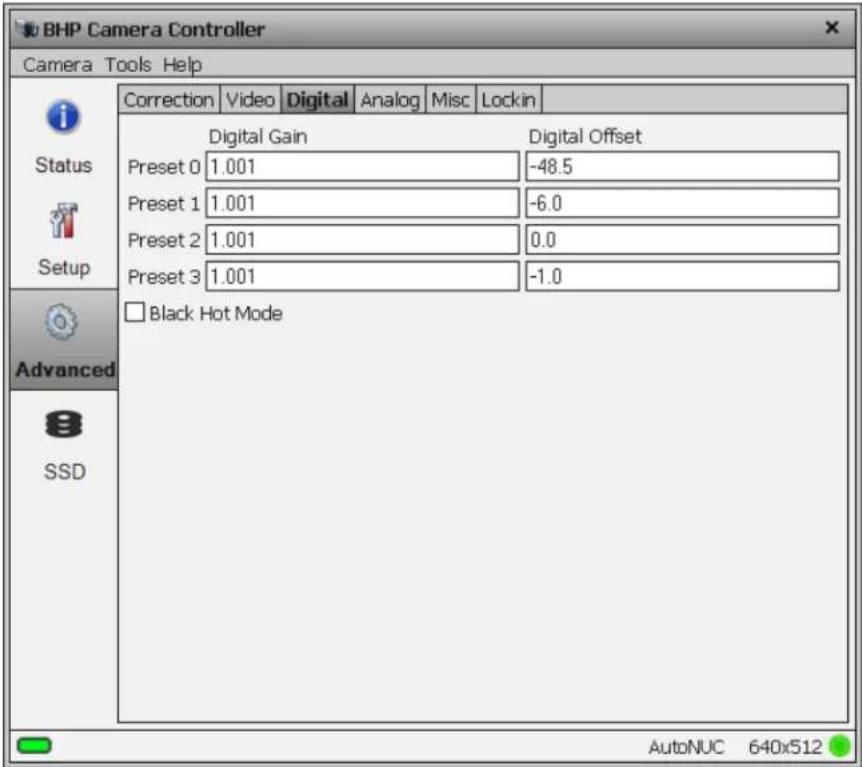
The digital gain and offset stages are digital features of the camera that allow the corrected digital output of the camera to be mapped to different output ranges. The following diagram illustrates the position of these stages in the signal path:
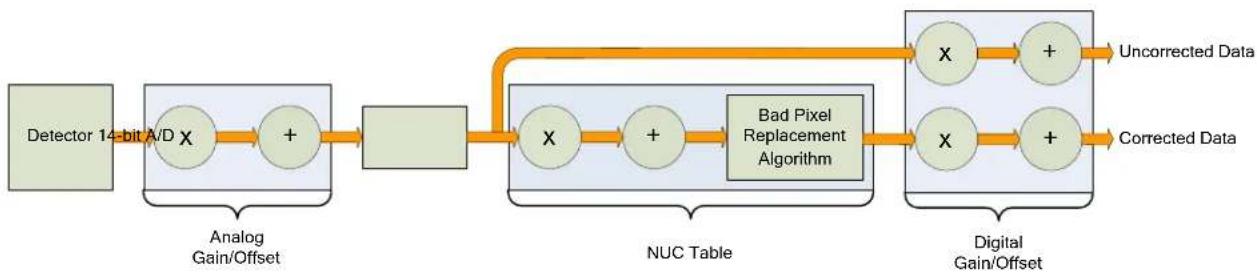
flowchart
graph LR
    A["Detector 14-bit A/D"] --> B["Analog Gain/Offset"]
    B --> C["+"]
    C --> D["Block"]
    D --> E["NUC Table"]
    E --> F["+"]
    F --> G["Bad Pixel Replacement Algorithm"]
    G --> H["Digital Gain/Offset"]
    H --> I["+"]
    I --> J["Uncorrected Data"]
    H --> K["+"]
    K --> L["Corrected Data"]
X-series Signal Processing Chain
The analog FPA data is passed through an analog gain and offset stage that are factory-set to ensure that the entire range of the FPA output is matched to the A/D input. This is shown in the figure below, which plots the digital output of a typical camera against background photon flux. The actual scale of the flux depends on integration time setting. The figure shows an example where the user desires to operate the camera between two flux points such that these two limits use the entire 14 bit range. With no global gain and offset adjustment these two points correspond to 3200 counts and 15800 counts for the low and high flux ranges respectively. Having obtained these numbers, we set the gain to use the full 14-bit range:
$$ = \text { gain } \frac {1 6 3 8 3}{- 3 2 0 0 1 5 8 0 0} = 3 0. $$
Since the offset stage is after the gain stage, we calculate the offset value using the gain:
$$ \text { offset } = - 3 2 0 0 \times \text { gain } = - 4 1 6 0 $$
These values are then entered into the global gain and offset controls and the linearized (red curve) transfer function shown is the result.
The available gain range is 1.999 to essentially zero; the available offset range is ± 32767 . The default values are a gain of 1 and an offset of zero. Because the system sensitivity (NEΔT) is set prior to the A/D stages, there is no detrimental effect on performance from the use of the global gain and offset controls.
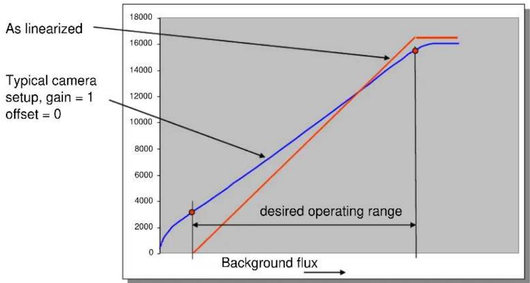
Use of global gain and offset to linearize the camera
5.4.3.7 Analog Tab
These parameters are set at the factory and are generally not adjusted by the user.
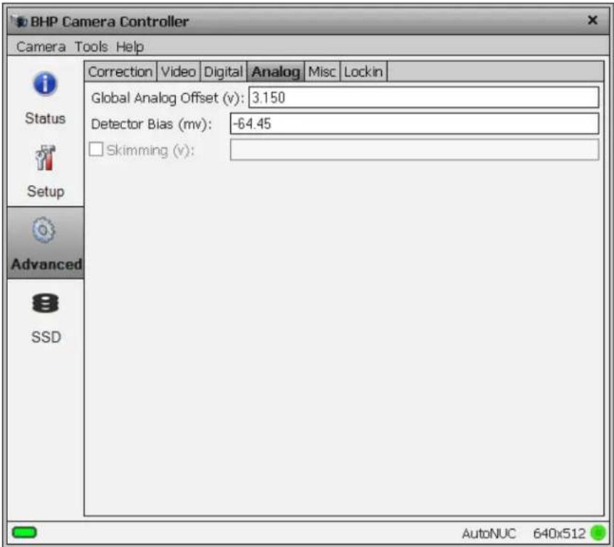
5.4.3.8 Misc Tab
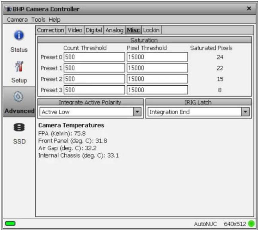
5.4.3.9 Lockin Tab
The lockin feature is designed for a non-destructive testing technique, where a periodic thermal excitation is applied to a part under test. An electrical signal that is synchronous with the excitation mechanism is also sent into the lockin input port on the camera's Auxiliary connector. This signal has its mean amplitude value and its period measured by the camera, and the results are stored in the image header metadata. An image sequence is acquired with this lockin metadata stored in the image header for each frame. This metadata is used for a post-acquisition analysis that can pull very weak signals out of the IR images and reveal defects in the part that are impossible to detect with conventional IR imaging techniques.
The signal period is determined by measuring the time interval between signal crossings of the digitizer midpoint value of 8192 counts, which is half of the 14-bit scale. The signal does not have to have any particular shape to get its period measured – it just has to be periodic. The lockin input has a 1.25 MHz sampling rate at 14 bits of depth, and selectable AC/DC coupling, with latency less than 1 microsecond. The input signal range is 0-5 volts. The frame period is the effective latency if it is used as a regular input, since it is only updated once per frame. When not used as a lockin input, this port still stores a value for each new image frame.
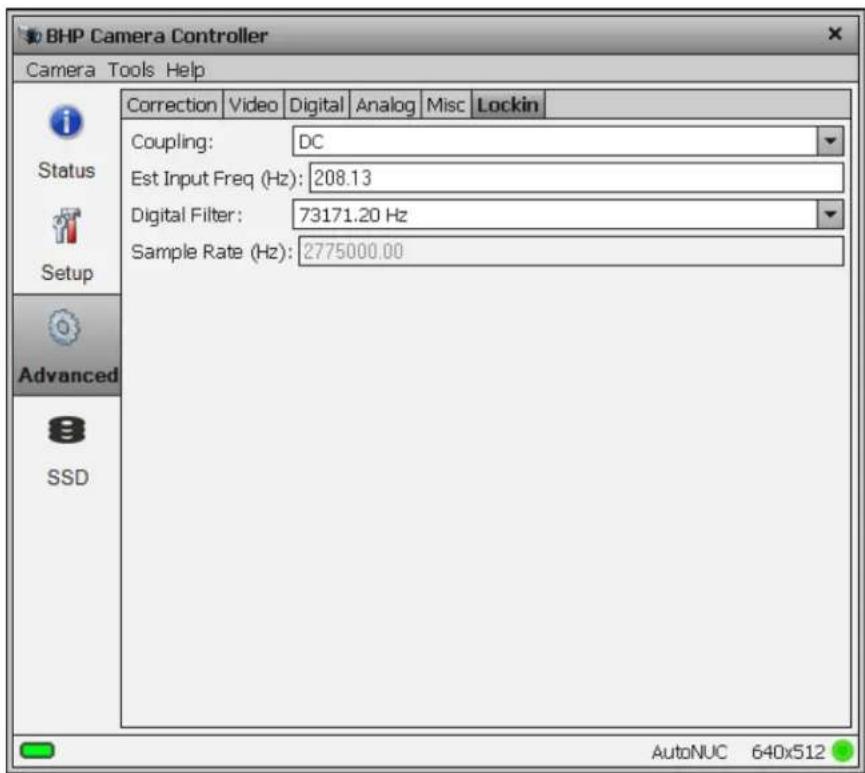
5.4.3.10 Saturation Detection
The camera can compare each pixel to a user defined threshold and count the number of pixels that exceed that threshold. Once that count has been determined for the entire frame, it is compared to threshold and sets a flag in the image header.
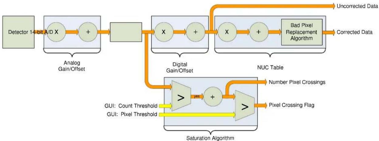
flowchart
graph TD
    A["Detector 14-bit A/D X"] --> B["+"]
    B --> C["Analog Gain/Offset"]
    C --> D["+"]
    D --> E["Digital Gain/Offset"]
    E --> F["X"]
    F --> G["+"]
    G --> H["NUC Table"]
    H --> I["Bad Pixel Replacement Algorithm"]
    I --> J["Corrected Data"]
    H --> K["NuC Table"]
    K --> L["Saturation Algorithm"]
    L --> M["Number Pixel Crossings"]
    L --> N["Pixel Crossing Flag"]
    L --> O["GUI: Count Threshold"]
    L --> P["GUI: Pixel Threshold"]
    Q["Uncorrected Data"] --> I
    R["yes"] --> S[">"]
    S --> T["+"]
    T --> U[">"]
Saturation Detection
One example of this feature is to use the information to adjust the integration time. If the A/D count threshold is set to 75% of the full value (12,288) then the camera will count the number of pixels that are within 25% of saturation. If a set number of pixels fit that criterion, then the integration period should be lowered.
It is important to note the camera does not account for bad pixels when counting for saturation. When determining the threshold, the user should account for the typical number of bad pixels.
5.4.3.10.1 Integrate Active Polarity
Sets the polarity (active high or low) of the Integrate Active signal on the camera rear chassis AUX connector.
5.4.3.10.2 IRIG Latch
The X6900 and X8500 cameras place the IRIG time in the header for each frame of video. The X6900 and X8500 can latch the IRIG data at the start of a frame, Frame Start, or in relation to the integration time, Integration Start or Integration End. Depending on the frame process selected (see Section 5.4.2.3.1.1) the Frame Start may indicate the time the integration starts or the time data is being passed out the camera. Latching the IRIG time on Integration Start or End marks the time the actual camera “exposure” occurred. The user should select the IRIG Latch value based on what action within the camera they need to know the exact time of.
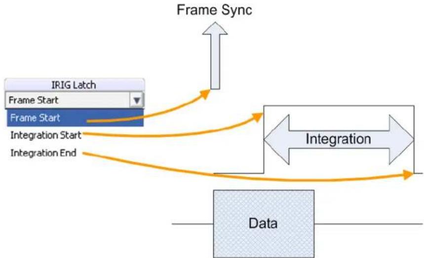
flowchart
graph TD
    A["IRIG Latch"] --> B["Frame Start"]
    B --> C["Frame Start"]
    C --> D["Integration Start"]
    C --> E["Integration End"]
    F["Data"] --> G["Integration"]
    G --> H["Frame Sync"]
    H --> I["Output"]
Figure 4-1: IRIG Latch Positions
5.4.3.10.3 Camera Temperatures
This part of the window displays the current temperature of the FPA, lens, and internal chassis temp sensors. These values are automatically updated every few seconds. If all the values are not visible, drag the corner of the controller window to make it larger.
Camera Temperatures FPA (Kelvin): 75.8 Front Panel (deg. C): 32.0 Air Gap (deg. C): 32.4 Internal Chassis (deg. C): 33.2
5.4.4 SSD Page
The SSD (Solid State Drive) page allow the user to control the functions related to the on-board recording functions. The X-Series cameras incorporate FLIR's Digital Video Image Recorder (DV-IR) system. The DV-IR system is a high-performance recording system that allows the user to record the image stream at any frame rate supported by the camera with zero dropped frames.
The DV-IR system is comprised of two main components, the RAM buffer and the SSD drive storage. The RAM buffer consists of 16GB of DDR-3 RAM. The RAM buffer is not removable but is volatile. All data in the buffer is erased when the camera is powered off. Because the buffer is volatile it is important that the camera power not be interrupted until the buffer data has been stored to another non-volatile storage medium. The primary non-volatile storage mechanism is the integrated SSD drive. The data in the buffer can also be played back over the camera's other digital interfaces (GigE, Camera Link, CoaXpress, SDI) so that it can be captured by external software or an external recorder.
The camera uses standard form factor flash drives used in PCs and laptops which can be obtained from a variety of retail outlets. FLIR recommends the use of premium quality SSD drives as these will typically have much faster read/write times.
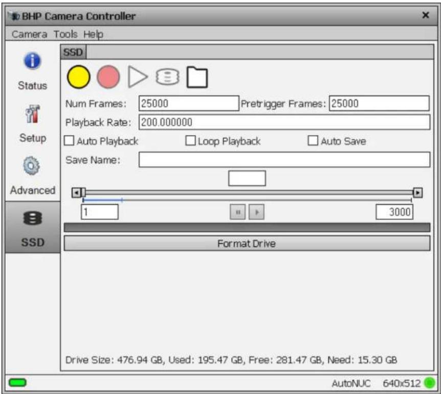
| SSD Functions | |
 | Arm Buffer. Press this button to prepare the system for a new recording. Once “armed”, the buffer will be configured according to the settings for Num Frames and Pretrigger frames. The system will start recording if the Record button on this page is pressed or if an external signal is applied to the RECORD input onthe rear panel of the camera.NOTE: Any data currently in the RAM buffer from a previous recording WILL BE LOST once the system is re-armed. |
 | Start Recording. Pressing this button will initial the recording of live data to the RAM buffer. This button will be disabled until the system is armed. |
 | Playback. Playback the data currently stored in the RAM buffer. This button is disabled during data recording. Data will be played at the rate indicated in the “Playback Rate” control. Setting a rate slower than the acquisition frame rate will result in a “slow-motion” playback effect. The data playback will occur over all interfaces simultaneously (GigE, Camera Link, CXP, video). Only Camera Link and CXP can handle the full frame rate of the camera. GigE will drop frames if the data playback is too fast. |
 | Store data in RAM Buffer to SSD. This is the fastest way to save the buffer. Speed will depend on SSD performance but with a high performance SSD it typically takes about 1.5x the record time to complete the save. The movie will be named according to the text in the “Save Name” field. The name is optional as all movies are also assigned a unique index number. |
 | Display SSD Contents. If an SSD is installed, pressing this button will display a list of movies it contains. |
| Num Frames | Sets the total number of images frames to be collected in the RAM buffer. This includes pre-trigger frames. |
| Pretrigger Frames | Set the number of frames to record prior to the trigger event.Once the recording system is armed, the camera will continuously write images to the RAM buffer. When the recording is triggered (either by the REC button in the controller or using an external trigger signal), the trigger frame is marked in the buffer. |
| Playback Rate | The rate, in Hz that data is played back from the RAM buffer. |
| Auto Playback | If enabled, RAM buffer playback will start immediately after the recording completes. |
| Loop Playback | If enabled, the playback will loop continuously until stopped by the user. |
| Auto Save | If enabled, the RAM buffer will be automatically saved to the SSD once the recording is completed. |
| Save Name | The text name given to the movie. This will be displayed in the SSD movie listing. Movies are organized on the SSD based on a unique index number assigned by the camera. The name is optional and if the name is not changed the same name will be given to multiple movies. The unique index will prevent that data would be overwritten. |
| Playback Controls | These controls allow the user to precisely control the playback limits. The start and stop frame can be set directly by the text boxes. The handles at the end of the blue line can also dragged by the mouse to set the limits. The gray bar controls the current playback position. The box above displays the current frame and can be edited to set the current frame manually. The handle on the bar can be dragged using the mouse to set the current frame. The buttons at the ends of the playback slider can be used to advance/rewind a single frame at a time. |
| Format Drive | This button can be used to clear the SSD drive. It is NOT a secure wipe. It only clears the Movie Allocation Table (MAT).NOTE: Although movies can be individually deleted using the folder icon, this does not necessarily make more space available for recording. In order to achieve consistent performance, the recording system must start new recordings at the end of the last recording. |
| Drive Size | Indicates total drive capacity |
| Used | Indicates space used by movies |
| Free | Indicates space available for new recordings |
| Need | Indicates space need to store data currently in RAM buffer |
5.4.4.1 Installing the SSD
The SSD storage is removable. It is a commonly available 2.5 inch SATA solid-state drive. The drive slot is located at the top of the camera's rear panel, as shown below. The drive slot is normally covered by a removable cap. To remove the cap, loosen the captive thumbscrews. The cap is mainly needed to secure the SSD when transporting the camera, or if there is a possibility of vibration that could unseat the drive. If the cap is not desired, it can be stored on the top of the camera, using the screw holes located on the right side of the upper heatsink, below the handle. With the cap removed, and no drive installed, the slot is still
covered by a spring-loaded door.
To install an SSD, insert the drive, connector end first, into the slot. Simply push the drive through the spring loaded door until it seats in the connector. The back of the drive will protrude slightly. This allows the drive to be gripped for removal. To remove the drive, simply pull the drive out. (There is no eject or release mechanism).
X-series User's Manual
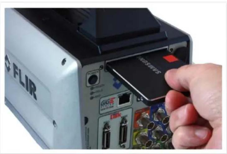
natural_image
Close-up of a FLIR device with a hand inserting a card into its internal ports (no visible text or symbols)The drive is hot-swappable and can be inserted or removed with the camera powered on or off. If the camera is on the SSD light on the rear panel will illuminate when a drive is detected.
The only time the drive should not be removed is when data from the RAM buffer is being written to the SSD.
Here is a typical commercially-available 2.5 inch SATA solid-state drive one can easily buy online for the X-series. These 2.5 inch drives can be had up to 4TB:

6 Interfaces
6.1 Mechanical Dimensions
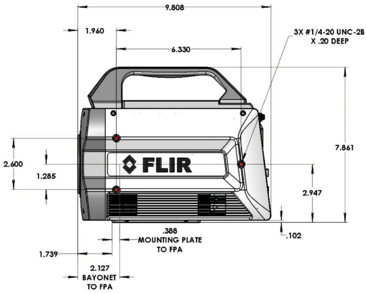
Side view of X-Series cameras with 4-tab bayonet lens interface and filter wheel
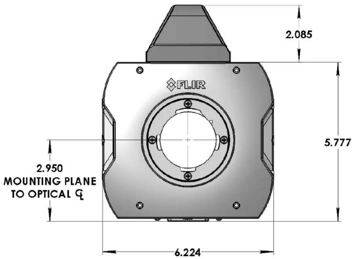
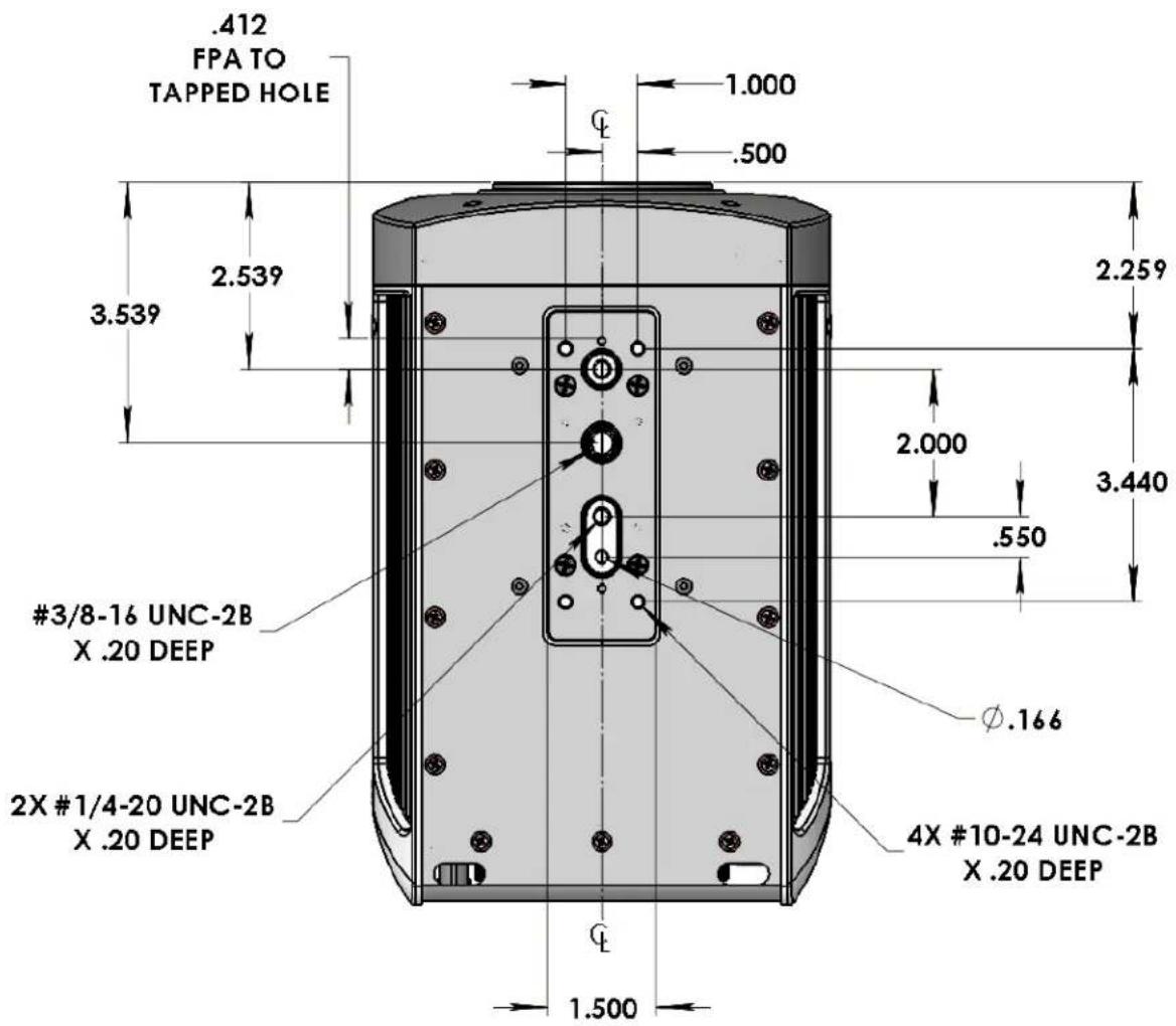
Front and bottom view of X-Series cameras with filter wheel
6.2 Electrical - X8500 and X6900 Series
The X8500 and X6900-Series cameras interface to the host computer through a variety of industry standards and camera specific signals. All pinouts and connectors are commercial standard types. All connections are on the back panel of the camera, as shown below. The last digit of the following section numbers corresponds to the callout numbers on the picture below.
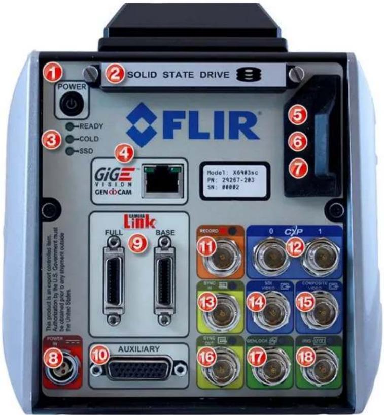
6.2.1 Power Switch

Illuminates when camera power is ON. Switch is mechanical and retains its ON/OFF statues through a power cycle. Camera power cannot be controlled remotely.
6.2.2 Solid State Drive
The X-series cameras use a standard form factor 2.5 inch SSD that is used in PCs and laptops and can be obtained from many retail outlets. A 512GB high performance SSD is provided with the cameras, and SSD drives with capacities up to 4TB are available. Using a high performance SSD will result in faster data transfers from RAM to the SSD.
The SSD is hot-swappable and can be removed at any time, EXCEPT when data from the RAM buffer is being written to the SSD. To remove the drive, remove the SSD cover. The cover is held in place by two thumb screws. The cover is optional but provides additional mechanical stability and provides accidental drive removal. Cover can be stored using screw holes located on side of the top handle. Then simply pull the drive from the slot. To insert the drive, insert the drive label up, connector end first into the drive slot until you feel the connector seat.
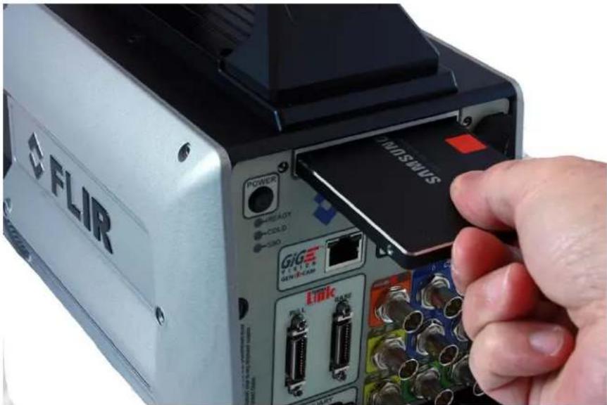
natural_image
Close-up of a FLIR device with attached GIGE Wireless port and power switch, being handled by a hand (no visible text or symbols on main subject)6.2.3 Status Lights
The X8500 and X6900-Series cameras provide a set of status indicators on the back panel to give the user some visual feedback on the camera operating state.
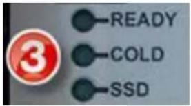 | READY: When on, Camera electronics have completed boot up. Camera is ready to accept commands. |
| COLD: When on, this indicates that the FPA has reached operating temperature (<80K). | |
| SSD: When on, this indicates that camera detects a Solid State Drive (SSD) is inserted. |
6.2.4 Gigabit Ethernet
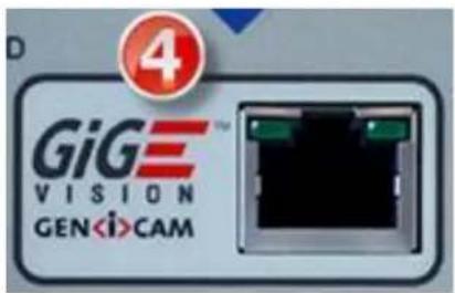
Gigabit Ethernet (GigE) is a common interface found in most PC's. The GigE interface can be used for image acquisition and/or camera control. The GigE interface is GEV/GenICam compliant. The GigE interface is the only digital data interface that cannot support the full data rate of the camera. This is because the camera maximum frame rate exceeds the bandwidth of GigE. It can support up to 30Hz frame rates at full resolution in the X8500-series cameras, and 125 fps in the X6900-series and X6800-series cameras at full resolution.
6.2.5 MicroSD
Not currently implemented. Reserved for future use.
6.2.6 USB Client
The USB Client is a Command and Control port for user interface, and it can also be used for firmware upgrades provided by FLIR. This port is USB2 compatible.
6.2.7 HDMI Video
When an HD video mode is selected, this output port is active. It is compatible with standard HDMI cables.
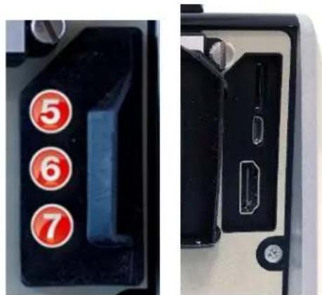
Behind the rubber flap on the back of the X-Series cameras there is a slot and two connectors as described below (from top to bottom):
MicroSD Card: This is not currently implemented and is reserved for future use.
USB Client: The USB Client is a Command and Control port for the user interface. This connector also can be used for firmware upgrades provided by FLIR. This port is USB2 compatible.
HDMI Video: When an HD video mode is selected, this output port is active. It is compatible with standard HDMI cables.
6.2.8 Power Interface

A 24VDC external AC-DC power converter is provided with the X-Series camera systems as a standard accessory. Power supply specifications are:
AC Input voltage range: 100-250VAC 50/60Hz
Current draw: 24 VDC at up to 4.0 amps input to the camera
Converter dimensions: 6.25 inches x 3.5 inches x 2.75 inch (L x W x H)
Converter weight: approximately 1 lb.
Pin1: +Power input
Pin2: Power return
Pin3: No connection
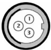
X-Series Camera Power Input Pinouts
When using your own DC power supply, you should take note of the following information:
Input voltage range: 24 volts DC nominal, 20-28V range
Current draw: 1.4 amps nominal steady state, 2.6 amps peak (during cool down)
X-Series camera power dissipation is < 50 Watts steady state at nominal ambient temperature.
Mating Connector: Fisher Connectors, S103A052-130+E31 103.1/5.7 +B. (FLIR PN 26399-000). The power cable should be 20AWG (stranded 10/30), 3 conductors, no shield, max diameter of 0.223 inches. (Example: Alphawire PN 882003)
6.2.9 Camera Link ^® Video Output
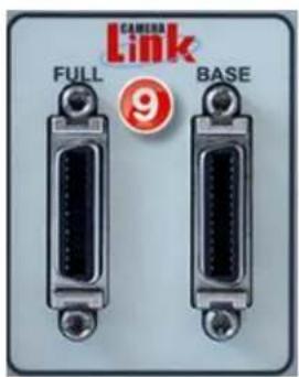
Camera Link® is a standard data interface for high end visible and IF cameras. The X-Series cameras use a Camera Link® Full interface in a 4-tap, 16-bit configuration, at 85Mhz. In terms of ports, the A and B ports are used with bit A0 being the LSB and bit B7 being the MSB of the data transferred. The header row uses the entire 16-bit value while the pixel data has a 14-bit range with the upper MSB's masked to "0".
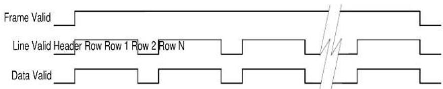
6.2.10 Auxiliary Connector/Breakout Cable
This connector provides access to a number of less commonly used input and output signals. The inputs and outputs are easily accessed using the Aux Breakout Cable (P/N 4212860) supplied with the camera. The camera auxiliary connector is a standard DB-26 (mating connector: Digikey PN A31505-ND).
| Pin | Signal | Level | Cable Molded-In Label | Connector Type |
| 2 | TX | RS-232 | Serial | DB9 Female connector |
| 4 | RX | RS-232 | ||
| 5 | GND | |||
| 10 | INTEG ACTIVE | TTL | 10 | BNC Male |
| 11 | GND | |||
| 14 | Reserved | 14 | BNC Male | |
| 15 | DIG_IN0 | 3V/5V CMOS | 15 | BNC Male |
| 16 | Reserved | 16 | BNC Male | |
| 17 | DIG_IN1 | 3V/5V CMOS | 17 | BNC Male |
| 18 | Reserved | 18 | BNC Male | |
| 19 | DIG_IN2 | 3V/5V CMOS | 19 | BNC Male |
| 20 | Reserved | 20 | BNC Male | |
| 21 | TRIG_IN | 3V/5V CMOS | 21 | BNC Male |
| 22 | GND | |||
| 23 | ANALOG_IN0 | 0-5V | 23 | BNC Male |
| 24 | ANALOG_IN1 | 0-5V | 24 | BNC Male |
| 25 | LOCKIN | 0-5V | 25 | BNC Male |
| 26 | GND |
Here is an image of the breakout cable, and a closeup of the molded-in number on Cable 20, which is reserved for future capabilities:
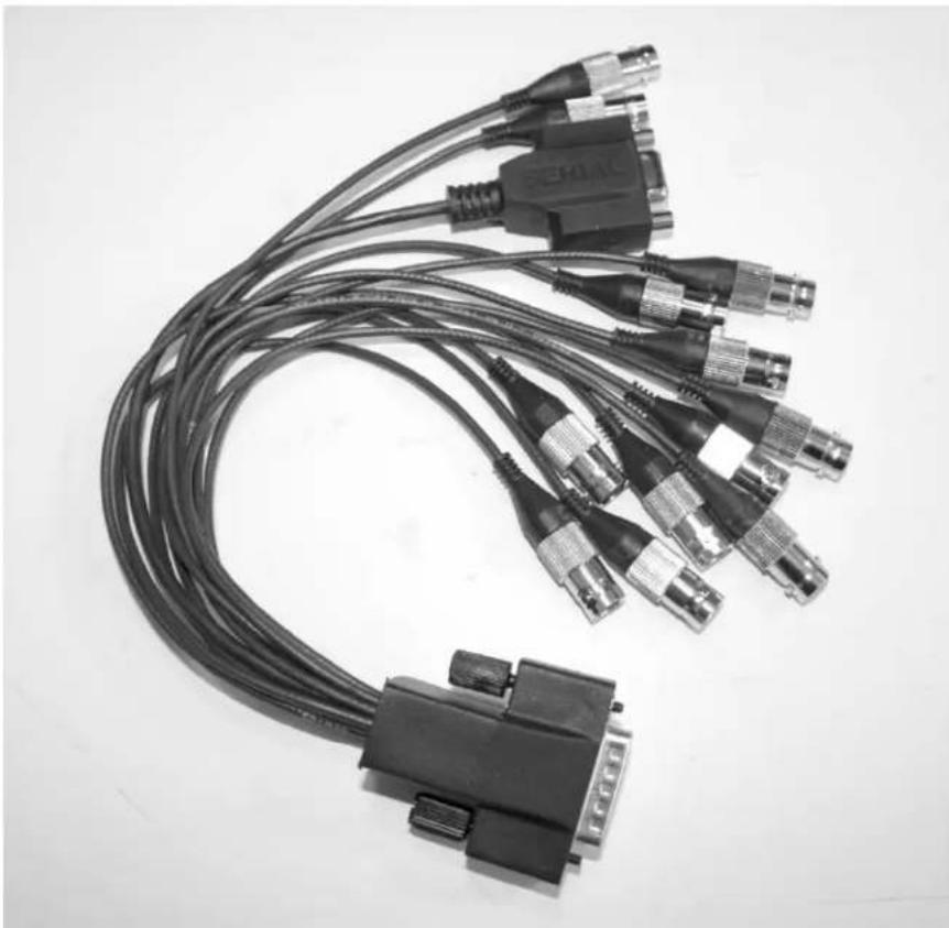
natural_image
Black-and-white photo of multiple connected audio/video cables with connectors and connectors (no visible text or symbols)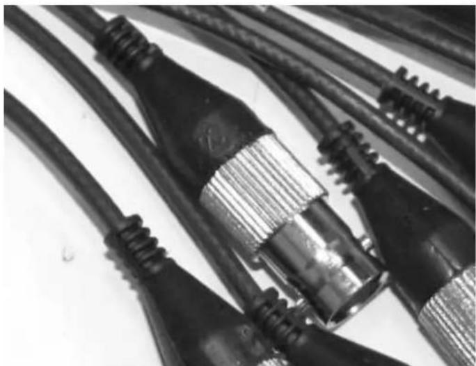
natural_image
Close-up of multiple black audio/video cables with threaded connectors (no visible text or symbols)6.2.11 Record Trigger
This input allows the user to use an external signal to start a recording to the internal RAM buffer. The input looks for a 3.3V CMOS "high" edge and is buffered to handle up to 5V. The LED indicator will flash when the recorder is armed (from the camera controller) and will be steady on during recording.
6.2.12 CoaXPress (CXP) Video Output [X6900/X8500 only]
![FLIR X8500sc - CoaXPress (CXP) Video Output [X6900/X8500 only] - 1](/content/2026/05/937015/images/8cd6d15c1f03e81c951a158f7ad13ce50c1b3473d6c467293c3199e0678200cb.jpg)
natural_image
Close-up of two metallic circular connectors with 'CXP' and number '12' labels, no readable text or symbols beyond markingsCXP is a standard interface for high speed digital video data. Unlike SDI, it can support flexible image sizes and frame rates. It uses common 75-ohm coax cables. The better the cable, the longer the transmission distance. The X8500 and X6900-Series cameras support dual CXP links at 5Gbps.
6.2.13 Sync In
The Sync In can be selected, by the user, to operate as an external Frame Sync to clock frames. It is a rising edge TTL signal with selectable polarity. The minimum width is 160nS. The LED will illuminate when a valid signal is present. (If the external sync rate is <1 Hz, the LED may blink). Nominal operating voltage is 0 to 5.5V. The absolute maximum range is -0.5V to 6.5V. Vih=2V, Vil=0.8V. Vih is the minimum voltage at which the camera will interpret the signal as a "high" and Vil is the maximum voltage at which the camera will interpret the signal as a "low".
6.2.14 HD-SDI [X6900/X8500 only]
HD-SDI is a standard HD video interface. This interface can transmit either 1080p or 720p video over distances up to 300f using standard RG-59 coax. Although monitors with direct SD inputs are typically found in the broadcast industry, off-the-shelf converters are available to convert SDI to HDMI for use with standard TV monitors.
6.2.15 Composite Video Output [X6900/X8500 only]
Composite video out (BNC connector). User selectable to be NTSC standard (640x480, 29.97Hz interlaced) or PAL standard (640x512, 25Hz interlaced). Video supports user selectable color palettes
6.2.16 Sync Out
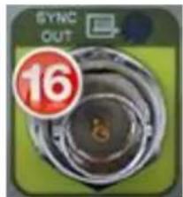
This TTL single ended signal is normally synchronous with the camera Sync In and can be used to synchronize other events to the camera when the camera is in a free run mode. It is also used in conjunction with the clock out signal to synchronize two X-Series cameras in master-slave fashion. When used in this way, the camera acting as the master makes appropriate adjustments to the camera sync out signal to assure that the data output of the two cameras is synchronized at the pixel level. This output is available in both ITR and IWR mode. The polarity is selectable.
6.2.17 Genlock Input [X6900/X8500 only]
![FLIR X8500sc - Genlock Input [X6900/X8500 only] - 1](/content/2026/05/937015/images/8337e722580ad0290afeba3acd2c5e801f303f2b5fc4d9dce91684a41c81f195.jpg)
natural_image
Close-up of a camera lens with a red circular badge showing the number 17 (no readable text or symbols beyond the badge)The purpose of the Genlock input is to allow the X-Series cameras to synchronize the active standard video output to an external video signal. The X-Series cameras can Genlock to both SD and HD video signals.
SD: If the current video output mode is for NTSC or PAL then the video fed to the Genlock input must match.
HD: If the current video mode is 720p/59.9/50 or 1080p/29.9/25 then the Genlock input signal needs to match. The input video can be HD-SDI or the Green channel of a component video (Tri-Sync). The camera will detect which type of signal is being used.
The Genlock LED will illuminate if there is a valid signal on the input and it matches the current camera video output type.
Because the camera itself can run at frame rates that can exceed standard video, it is important to note that by itself, Genlock is only synchronizing the standard video output to the Genlock input. I you wish to lock the FPA clock to the Genlock input signal you must also change the Sync Source from Internal to Video [Sec. 5.4.2.3.2]
6.2.18 IRIG Input [X6900/X8500 only]
![FLIR X8500sc - IRIG Input [X6900/X8500 only] - 1](/content/2026/05/937015/images/eefbbc4d9bffdbfe6452e3ab28a0e6df50c83aa4c6bd1ea5bf1e34e5edf7cd9e.jpg)
natural_image
Close-up of a camera lens on a green screen with a red circular badge showing '18' and '2.00' (no readable text or symbols beyond the badge)An IRIG-B decoder is built into the camera to allow for time stamping of each frame as well as support triggered data acquisition at user programmed times. The IRIG clock can decode IRIG-B-AM. Optimal format is B122 but other B12x formats should work, however, extra data (such as the year) will not be decoded.
The LED will illuminate when camera is locked to an external IRIG signal.
7 Filter Wheel
The X-Series cameras have a 4-position, motorized, warm filter wheel. The wheel sits between the lens and the detector warm window. The filter wheel can be seen by removing the lens as shown in the picture below.
The filter wheel can be controlled from the camera controller [Sec. 5.4.2.4.2]. The filters are held in a removable holder (shown below). Each holder can hold one filter up to 2mm thick, or two filters with a combined thickness of 2mm.
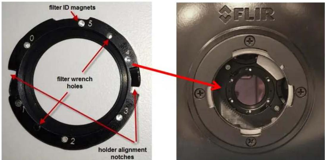
The camera keeps track of what filters are in the wheel by sensing a set of magnets installed in the holder. The camera scans the wheel on boot up (or on demand). The filter page in the camera controller displays the detected filter IDs. If a factory calibration range is selected that requires a filter, the camera will automatically search the wheel for that filter and put it in the field of view.
In most cases the filter wheel will be populated at the factory. If a user has more filters than can fit in the wheel at one time, it is easy to swap a filter. To do this you will need the filter wrench that is included in the shipping case with each camera. It looks like the picture to the right.
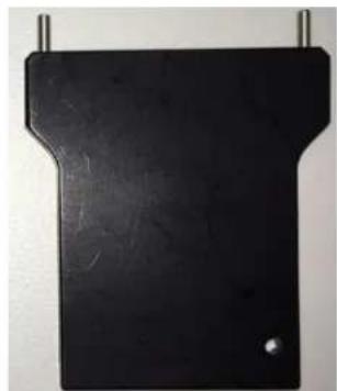
natural_image
Black rectangular object with a T-shaped top and small dot at the bottom, suspended by two metal rods (no text or symbols visible)To remove a filter, first remove the camera lens, so you can see the filter wheel. Then, go to the Setup>>Filter/Flag page in the controller and press the "C" button next to the filter you wish to change. The camera will put this filter in front of the detector, where it can be seen. Each filter holder has two holes (located between filter ID slots 1&2 and 4&5, at the 3 o'clock and 9'oclock positions when installed). Insert the two pins on the wrench into these holes. Twist gently a few degrees counter-clockwise and you will feel the holder click free of the retention springs.
Gently pull the wrench from the camera and the filter holder should stay with the wrench.
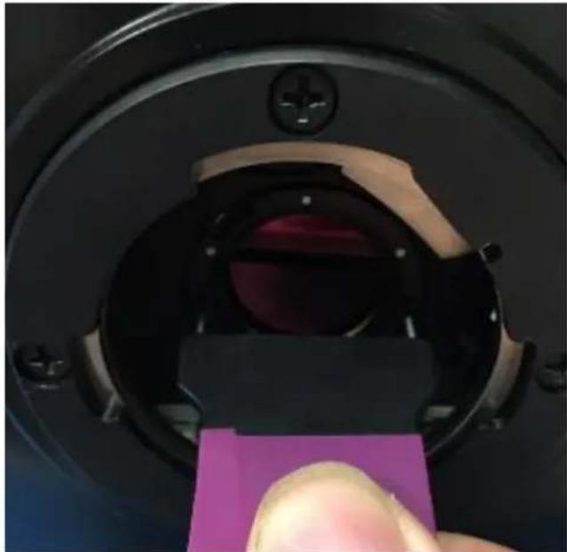
natural_image
Close-up of a black mechanical component with a purple square patch, being held by a finger (no visible text or symbols)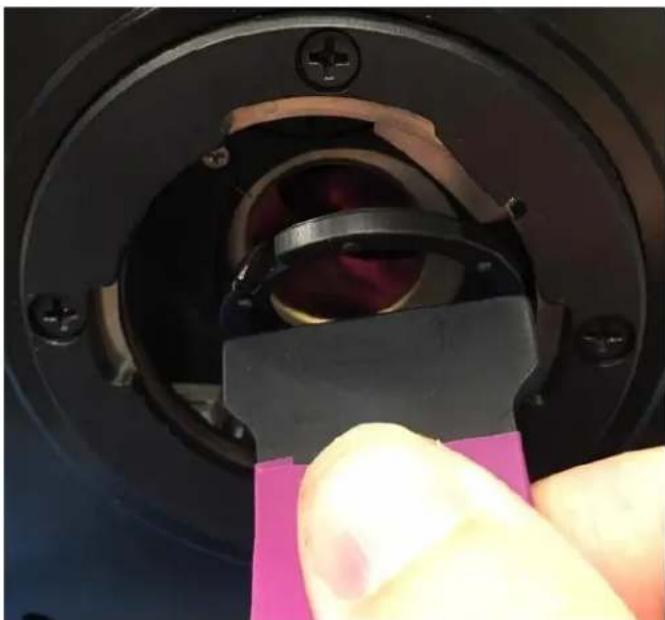
natural_image
Close-up of a hand holding a black plastic clip with a yellow lens inside a circular mechanical component (no text or symbols visible)To install the new filter, put the holder on the wrench, with the ID numbers facing you. Align the notches (between ID positions 0&1 and 4&3) with the retention springs and seat the holder in the wheel so that the front of the holder is flush with the wheel. Turn gently (but firmly) a few degrees clockwise until you feel the holder click into position. On the Setup>>Filter/Flag page of the controller, press the scan button to refresh the filter list in the camera.
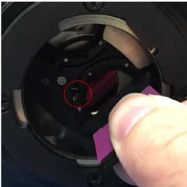
natural_image
Close-up of a hand holding a black mechanical component with a red circular annotation and purple tab, no visible text or symbols.8 Specifications
8.1 Interface
| AC Power | 90-230 V_AC , 50-60 Hz (using FLIR 24123-000 power supply) |
| Control | Gigabit Ethernet, USB, Camera Link Serial, CXP or RS-232 |
| Standard Video Outputs (where applicable) | NTSC/PAL selectable, BNC, 75Ω, 1V pk-pkHDMI (720p 50/59.94, 1080p 25/29.97)HD-SDI (720p 50/59.94, 1080p 25/29.97) |
| Frame Sync In | TTL singled ended, BNC, selectable polarity, >160ns pulse width |
| Frame Sync Out | TTL singled ended, BNC, selectable polarity, 160ns pulse width |
| Trigger In | TTL singled ended, AUX, selectable polarity, >160ns pulse width |
| Integration Out | TTL singled ended, AUX, selectable polarity |
| Genlock In | SD: Composite sync input, field and lines sync of video outputHD: HD-SDI or Tri-level Sync |
| IRIG-B in | IRIG-B-AM, B122 format, BNC |
| Digital Video Out | 14-bit Camera Link Full, and Gigabit Ethernet, Dual-link CXP @ 5Gbps |
| Optical Interface | FLIR HDC bayonet |
| Thermal Interface | Sealed enclosure with integral forced air heat exchanger; bottom mounting surface provides direct heat path for low atmospheric pressure environments |
| Mechanical Interface | 2 (two) 1⁄4-20 tripod screws; 1 (one) 3/8-16 professional tripod screw; 4 (four) 10-24 mount holes. 3x 1⁄4-20 screws each side |
8.2 Windowing Capacity
| Minimum Window Size | X6800/X6900: 32 columns x 4 rowsX8500: 64 columns x 4 rows |
| Windowing Step Size | X6800/X6900: 32 columns x 4 rowsX8500: 64 columns x 4 rows |
| Maximum Window Size | X6800/X6900: 640 columns x 512 rowsX8500: 1280 columns x 1024 rows |
| Window Offset Step Size | 32 columns; 4 rows |
8.3 Acquisition Modes and Features
| Frame Rate (X6800):Max at Full WindowMax at Minimum WindowMinimumResolution | 520.91 Hz (< 1.906mS Integration Width)23076.92 Hz (<30uS Integration Width)1.45mHz90nS |
| Frame Rate (X6900):Max at Full WindowMax at Minimum WindowMinimumResolution | 1004 Hz (< 0.996mS Integration Width)29113 Hz (< 34.3uS Integration Width)1.45mHz90nS |
| Frame Rate (X8500):Max at Full WindowMax at Minimum WindowMinimumResolution | 181 Hz (< 5.52mS Integration Width)6026 Hz (< 166uS Integration Width)1.45mHz90nS |
| Pixel Rate (burst) | 355 MHz |
| Integration WidthMaximumMinimumResolution | >98% selected frame time (1/frame rate)270 nanoseconds90 nanoseconds |
| Synchronization Modes | Genlock: synchronizes composite video to external composite video source or HDMI/SDI to external SDI or "Y" signal from component signal (Not available in X6800)Frame Sync Starts Integration: synchronizes FPA integration to external sync sourceFrame Sync Starts Readout: synchronizes FPA data readout to external sync source |
| Preset Sequencing | 4 presets programmable for 1 to 4,294,967,295 frames eachPreset sequence programmable for up to 4,294,967,295 sequences per triggered event |
| Digital Video Output | Selectable:Raw digital video (14-bits)Gain and offset (NUC) corrected (14-bits)NUC with bad pixel replaced (14-bits) |
| Digital Gain and Offset | Variable, per presetGlobal Gain: 0→3.9; 2-14resolutionGlobal Offset: ± full A/D resolution |
8.4 Analog Video
| Video Output | SelectableHD-SDI (Not available in X6800)HDMINTSC/PAL composite (Not available in X6800) |
| Data Output | SelectableRaw, uncorrectedCorrected |
| MGC | Linear scaled with user controlled gain and offset |
| AGC | SelectableDDEPlateau based equalizationLinear equalization |
| AGC Filter | User controlled damping factorUser controlled update rate |
| Display ROI | ROI of camera image can be selected and displayed |
| Overlay | Available on all standard video outputs |
| Palettes | SelectableGrayscaleVarious color palettes |
| Zoom | Selectablex1/2x14:3 (SD to HD)x2x4 |
| Temporal Filter | N/A |
| Brightness and Contrast (analog video) | User controlled to increase or decrease |
| Video Boresight | +/- 16 rows |
8.5 Performance Characteristics
| Power ConsumptionFLIR PWR Supply @ 120VAC | Continuous Cool Down: 50 VAContinuous Normal: 41 VAContinuous Normal w/NUC Flag: 75 VA |
| Power ConsumptionCamera DC Power @ 24VDC | Continuous Cool Down: 24 WattsContinuous Normal: 21.25 WattsContinuous Normal w/NUC Flag: 36 Watts |
| Cool-Down Time | ≈7 minutes to reach operating temperature |
| Sensitivity (w/o optics)NEΔT1 | InSb: <20mK (18 mK typ.)SLS: <45mK (40 mK typ.) |
| Factory CalibrationTemperature MeasurementRanges | InSb:-20°C to 350°C (-4°F to 662°F)45°C to 600°C (113°F to 1,112°F)250°C to 2000°C (482°F to 3,632°F)500°C to 3,000°C (932°F to 5,432°F)SLS:-20°C to 650°C (-4°F to 1,202°F)250°C to 1,500°C (482°F to 3,632°F)500°C to 3000°C (932°F to 5,432°F) |
| Factory CalibrationTemperature MeasurementAccuracy2 | ±1°C or ±1% of reading0°C to +3000°C (17mm, 25mm, 50mm, 100mm, 200mm Lenses)±2°C or ±2% of reading-20°C to 0°C (17mm, 25mm, 50mm, 100mm, 200mm lenses)-10°C to +500°C (1X & 4X Closeup lenses) |
1) NEΔT is at 50% nominal bucket fill, 298K background, +5 °C signal
2) Assuming ideal laboratory conditions (close range, known high emissivity targets, stabilized camera and lens temperatures) and only if the lens and camera are matched, i.e. not a 3-5 micron lens on a broadband camera.
8.6 Non Uniformity Correction
| NUC Types | One Point (offset value with unity gain)Two Point (offset and gain values, non-volatile)Two Point w/Bad Pixel Detection/ReplacementUpdate Offset (recalculates offset using current gain, volatile) |
| NUC Source | Internal: TE controlled flagExternal: Any user supplied source which covers entire window |
| Bad Pixel Replacement | Two-Point Gradient, or nearest neighbor |
| Number of NUC's | 4 active NUC's in preset selectable formGreater than 24 full frame NUC's saved in camera memory |
| NUC Time | < 5 seconds |
| NUC Performance | Residual Non-Uniformity: 0.1% |
8.7 Detector/FPA
| Spectral Response | Xxx00sc/xx02: 1.5-5um; Xxx01/xx03: 3-5um |
| Detector Type | InSb or Type 2 SLS |
| Detector f/# | f/2.5 or f/4 |
| Supported ROIC | X6800/X6900: ISC0804X8500: ISC1308 |
| Integration Mode | Snapshot |
| Format (HxV) | X6800/X6900: 640x512X8500: 1280x1024 |
| Operability | >99.5%, 99.9% typical |
| Charge Handling Capacity | X6800/X6900: 11.0 x 10^6 carriersX8500 (InSb) : Gain 0: 3.0 x 10^6 carriersX8500 (SLS) : Gain 1: 11.5 x 10^6 carrier |
| Detector Pitch | X6800/X6900: 25 micronsX8500: 12 microns |
| Detector Cooling | Linear Sterling Cooler |
8.8 General Characteristics
| Size | |
| Length | 249 mm (9.8 inches), not including lens or lens cover |
| Width | 156 mm (6.2 inches) |
| Height | 201 mm (7.9 inches) w/ handle, 147 mm (5.8 inches) w/o handle |
| Weight | 6.4 kg (14 lbs.), not including lens or lens cover |
| Temperature | |
| Operating Storage | -20C to +50C-55C to +80C |
| Shock | 40 g's, 11msec half sine pulse |
| Vibration | 4.3 g's RMS random vibration, all three axes |
| Humidity | <95% relative humidity, non-condensing |
| Altitude | 0 to 40,000 feet operational, 0 to 70,000 feet non-operational |
| Operating Orientation | No restriction in orientation |
9 Maintenance
9.1 Camera and Lens Cleaning
9.1.1 Camera Body, Cables and Accessories
The camera body, cables and accessories may be cleaned by wiping with a soft cloth. To remove stains, wipe with a soft cloth moistened with a mild detergent solution and wrung dry, then wipe with a dry soft cloth.
Do not use benzene, thinner, or any other chemical product on the camera, the cables or the accessories, as this may cause deterioration.
9.1.2 Lenses
It is recommended that all optics be handled with care and the need for cleaning is eliminated or at least reduced. If, however, cleaning is deemed necessary, the methods herein are accepted industry standards and should yield good results.
Before you BEGIN:
Identify the type of optic to be cleaned.
- Is it hard or soft material?
- Is it coated & with what?
How is it contaminated?
- Particulate or film or both.
Set a standard of cleanliness.
- What is clean enough?
- Establish & document a standard.
Know your solvent.
Read the MSDS
- See recommended solvents
Assemble your supplies:
- Latex gloves
- Clean, well-lit work area
□ Inspection light - Lens tissue or cloth
- Dust bulb or filtered air
- Proper solvent
- Solvent dispenser
The Drag Wipe Method:
Set-up a clean area to work from with an anti-roll barrier around the edge to prevent anything from leaving the table.
Use a clean, lint free cloth or lens tissue.
Wear latex gloves - clean them with alcohol or detergent before handling optic.
NEVER touch the face of the optic with your fingers.
Cover the optic and store in a dry - dust free area immediately after cleaning.
- Blow or brush loose particles from surface. Don't let them contaminate your work area. Use air from a can or a filtered source.
- Apply solvent directly to your cloth. Use slow, even, light pressure working from edge to edge across the optic.
Recommended Solvents
| Material | Solvent | ||
| Fused Silica | 1,2,3,4 | Zinc Selenide | 1,2,4 |
| BK-7 | 1,2,3,4 | Zinc Sulfide | 1,2,4 |
| Optical Crown Glass | 1,2,3,4 | Sapphire | 1,2,3,4 |
| Zerodur | 1,2,3,4 | ||
| Calcium Fluoride | 1,2,4 | Coated Optics | |
| Magnesium Fluoride | 1,2,4 | Dielectric coating | 1,2,3,4 |
| Sodium Chloride | Nitrogen | Interference filters | 3 |
| Potassium Chloride | Nitrogen | Soft metallic coating | Air only |
| Potassium Bromide | Nitrogen | Hard/Protected metallic | 1,2,3,4 |
| Thallium Bromoiodide | Nitrogen |
1] Water free Acetone
2] Ethanol
3] Methanol
4] Isopropanol
- X-Series Science Camera
- Table of Contents
- REVISION HISTORY ......6
- INTRODUCTION....7
- WARNINGS AND CAUTIONS....12
- INSTALLATION....13
- X-SERIES CAMERA CONTROLLER....17
- FILTER WHEEL....81
- SPECIFICATIONS 83
- MAINTENANCE....90
- Revision History
- Introduction
- Camera System Components
- Camera Models
- System Overview
- Key features of the X-Series science cameras
- Improved Linearity to Zero Well-Fill
- Fast Frame Rates
- 14-Bit Digital Image Data
- Windowing Capability
- Presets
- Factory Calibrations
- Independently Adjustable Frame Rates
- Multiple Triggering Modes and Synchronizing Interfaces
- Adjustable Digital Gains and Offsets
- Multiple Control Options
- The X6800 camera supports:
- Multiple Video Outputs
- Support for Camera Link Full or CoaXpress interfaces
- Video Color Palettes
- Video Overlay
- Ruggedized Construction
- Digital Detail Enhancement (DDE)
- On-Camera NUCs with Auto Update
- IRIG Time Stamp (TSPI Accurate)
- 4-position filter wheel
- On-board recording with Solid State Drive (SSD) storage
- Warnings and Cautions
- Warnings and Cautions:
- Installation
- Basic Connections
- X-Series Camera Controller
- Online Help
- Menu Bar
- Tools Menu
- Advanced Time Controls
- Help Menu
- Basic User Mode
- Status Page
- Setup Page
- Correction Page
- Advanced User Mode
- Status Page
- Setup Page
- Presets Tab
- Single Preset Mode
- Preset Sequencing Mode
- Preset Sequencing
- Optimized vs. Traditional Preset Sequencing
- Superframing Mode
- Optimized vs. Traditional Superframing:
- Traditional Superframing
- Optimized Superframing
- Window Tab
- FPA Sub-tab
- Analog Video sub-tab
- Sync Tab
- Sync Mode
- Frame Sync Starts Integration (FSSI)
- Sync Options
- Sync Out
- Filter/Flag
- Flag controls
- Filter Wheel Controls
- Advanced Page
- Non-Uniformity Correction (NUC)
- One-Point Correction Process
- Two-Point Correction Process
- Update Offset
- Bad Pixel Correction
- Correction Tab
- NUC Information
- Load NUC Options
- Performing a NUC
- of frames to use to
- Video Setup Tab
- Video ROI
- Video Overlay Tab
- Digital Tab
- X-series Signal Processing Chain
- Analog Tab
- Misc Tab
- Lockin Tab
- Saturation Detection
- Integrate Active Polarity
- IRIG Latch
- Camera Temperatures
- SSD Page
- Installing the SSD
- The only time the drive should not be removed is when data from the RAM buffer is being written to the SSD.
- Interfaces
- Mechanical Dimensions
- Electrical - X8500 and X6900 Series
- Power Switch
- Solid State Drive
- Status Lights
- Gigabit Ethernet
- MicroSD
- USB Client
- HDMI Video
- Power Interface
- X-Series Camera Power Input Pinouts
- Camera Link ® Video Output
- Auxiliary Connector/Breakout Cable
- Record Trigger
- CoaXPress (CXP) Video Output [X6900/X8500 only]
- Sync In
- HD-SDI [X6900/X8500 only]
- Composite Video Output [X6900/X8500 only]
- Sync Out
- Genlock Input [X6900/X8500 only]
- IRIG Input [X6900/X8500 only]
- Filter Wheel
- Specifications
- Interface
- Windowing Capacity
- Performance Characteristics
- Non Uniformity Correction
- Detector/FPA
- General Characteristics
- Maintenance
- Camera and Lens Cleaning
- Camera Body, Cables and Accessories
- Lenses
Brand : FLIR
Model : X8500sc
Category : Camera