
AC1200 - Router Hikvision - Free user manual and instructions
Find the device manual for free AC1200 Hikvision in PDF.


| Product Type | Wireless Router |
| Model | DS-3WR12C, DS-3WR12GC |
| Wireless Standards | IEEE 802.11a/b/g/n/ac |
| Frequency Bands | 2.4 GHz and 5 GHz |
| Maximum Wireless Rate | 1167 Mbps (2.4 GHz: 300 Mbps, 5 GHz: 867 Mbps) |
| Ports | 1 WAN (10/100 Mbps), 3 LAN (10/100 Mbps, one configurable as IPTV) |
| Power Supply | DC 9V, 1A (included adapter) |
| LED Indicator | Power/Status (solid on, blinking slow, blinking fast) |
| Antennas | 3 external |
| Security | WPA/WPA2-PSK, WPS (PIN and PBC) |
| IPv6 Support | Yes (PPPoEv6, DHCPv6, Static IPv6) |
| Operating Modes | Router, WISP, Universal Relay, Access Point |
| Beamforming | Supported (enabled by default) |
| Guest Network | Supported (with bandwidth limit and validity time) |
| Parental Control | Supported (time and access control) |
| Access Control | Supported (bandwidth limit, blacklist) |
| DDNS | Supported |
| DMZ Host | Supported |
| Port Mapping | Supported |
| IP-MAC Binding | Supported |
| MAC Address Filter | Supported |
| Firewall | Built-in |
| Operating Temperature | 0°C to 40°C |
| Storage Temperature | -40°C to 70°C |
| Humidity | 10% to 90% non-condensing |
| Maintenance | Keep dry; clean with soft dry cloth |
Frequently Asked Questions - AC1200 Hikvision
User questions about AC1200 Hikvision
0 question about this device. Answer the ones you know or ask your own.
Ask a new question about this device
Download the instructions for your Router in PDF format for free! Find your manual AC1200 - Hikvision and take your electronic device back in hand. On this page are published all the documents necessary for the use of your device. AC1200 by Hikvision.
USER MANUAL AC1200 Hikvision
© 2022 Hangzhou Hikvision Digital Technology Co., Ltd. All rights reserved.
About this Manual
The Manual includes instructions for using and managing the Product. Pictures, charts, images and all other information hereinafter are for description and explanation only. The information contained in the Manual is subject to change, without notice, due to firmware updates or other reasons. Please find the latest version of this Manual at the Hikvision website (https://www.hikvision.com/).
Please use this Manual with the guidance and assistance of professionals trained in supporting the Product.
Trademarks
HIKVISION and other Hikvision's trademarks and logos are the properties of Hikvision in various jurisdictions.
Other trademarks and logos mentioned are the properties of their respective owners.
Disclaimer
TO THE MAXIMUM EXTENT PERMITTED BY APPLICABLE LAW, THIS MANUAL AND THE PRODUCT DESCRIBED, WITH ITS HARDWARE, SOFTWARE AND FIRMWARE, ARE PROVIDED "AS IS" AND "WITH ALL FAULTS AND ERRORS". HIKVISION MAKES NO WARRANTIES, EXPRESS OR IMPLIED, INCLUDING WITHOUT LIMITATION, MERCHANTABILITY, SATISFACTORY QUALITY, OR FITNESS FOR A PARTICULAR PURPOSE. THE USE OF THE PRODUCT BY YOU IS AT YOUR OWN RISK. IN NO EVENT WILL HIKVISION BE LIABLE TO YOU FOR ANY SPECIAL, CONSEQUENTIAL, INCIDENTAL, OR INDIRECT DAMAGES, INCLUDING, AMONG OTHERS, DAMAGES FOR LOSS OF BUSINESS PROFITS, BUSINESS INTERRUPTION, OR LOSS OF DATA, CORRUPTION OF SYSTEMS, OR LOSS OF DOCUMENTATION, WHETHER BASED ON BREACH OF CONTRACT, TORT (INCLUDING NEGLIGENCE), PRODUCT LIABILITY, OR OTHERWISE, IN CONNECTION WITH THE USE OF THE PRODUCT, EVEN IF HIKVISION HAS BEEN ADVISED OF THE POSSIBILITY OF SUCH DAMAGES OR LOSS.
YOU ACKNOWLEDGE THAT THE NATURE OF THE INTERNET PROVIDES FOR INHERENT SECURITY RISKS, AND HIKVISION SHALL NOT TAKE ANY RESPONSIBILITIES FOR ABNORMAL OPERATION, PRIVACY LEAKAGE OR OTHER DAMAGES RESULTING FROM CYBER-ATTACK, HACKER ATTACK, VIRUS INFECTION, OR OTHER INTERNET SECURITY RISKS; HOWEVER, HIKVISION WILL PROVIDE TIMELY TECHNICAL SUPPORT IF REQUIRED.
YOU AGREE TO USE THIS PRODUCT IN COMPLIANCE WITH ALL APPLICABLE LAWS, AND YOU ARE SOLELY RESPONSIBLE FOR ENSURING THAT YOUR USE CONFORMS TO THE APPLICABLE LAW. ESPECIALLY, YOU ARE RESPONSIBLE, FOR USING THIS PRODUCT IN A MANNER THAT DOES NOT INFRINGE ON THE RIGHTS OF THIRD PARTIES, INCLUDING WITHOUT LIMITATION, RIGHTS OF PUBLICITY, INTELLECTUAL PROPERTY RIGHTS, OR DATA PROTECTION AND OTHER PRIVACY RIGHTS. YOU SHALL NOT USE THIS PRODUCT FOR ANY PROHIBITED END-USES, INCLUDING THE DEVELOPMENT OR PRODUCTION OF WEAPONS OF MASS DESTRUCTION, THE DEVELOPMENT OR PRODUCTION OF CHEMICAL OR BIOLOGICAL WEAPONS, ANY ACTIVITIES IN THE CONTEXT RELATED TO ANY NUCLEAR EXPLOSIVE OR UNSAFE NUCLEAR FUEL-CYCLE, OR IN SUPPORT OF HUMAN RIGHTS ABUSES.
IN THE EVENT OF ANY CONFLICTS BETWEEN THIS MANUAL AND THE APPLICABLE LAW, THE LATTER PREVAILS.
Regulatory Information
FCC Information
Please take attention that changes or modification not expressly approved by the party responsible for compliance could void the user's authority to operate the equipment.
FCC Compliance
This equipment has been tested and found to comply with the limits for a Class A digital device, pursuant to part 15 of the FCC Rules. These limits are designed to provide reasonable protection against harmful interference when the equipment is operated in a commercial environment. This equipment generates, uses, and can radiate radio frequency energy and, if not installed and used in accordance with the instruction manual, may cause harmful interference to radio communications. Operation of this equipment in a residential area is likely to cause harmful interference in which case the user will be required to correct the interference at his own expense.
FCC Conditions
This device complies with part 15 of the FCC Rules. Operation is subject to the following two conditions:
- This device may not cause harmful interference.
- This device must accept any interference received, including interference that may cause undesired operation.
EU Conformity Statement
CE This product and - if applicable - the supplied accessories too are marked with "CE" and comply therefore with the applicable harmonized European standards listed under the Directive 2014/30/EU, the Directive 2014/35/EU, the Directive 2011/65/EU.
Hereby, Hikvision declares that the radio equipment type Wireless Router is in compliance with Directive 2014/53/EU. The full text of the EU declaration of conformity is available at the following internet address: https://www.hikvision.com/europe/support/download/declaration-of-conformity/
| Model | Received frequency | Transmitted frequency | Bandwidth | Transmit power |
| DS-3WR12C | 2400-2483.5 MHz5150-5250 MHz | 2412-2472 MHz5180-5240 MHz | 2.4 GHz: 20 MHz and 40 MHz5 GHz: 20 MHz, 40 MHz and 80 MHz | 2.4 GHz:19.86 dBm5 GHz:22.96 dBm |
| DS-3WR12GC | 2400-2483.5 MHz5150-5250 MHz | 2.4 GHz:19.5 dBm5 GHz:22.5 dBm |

2012/19/EU (WEEE directive): Products marked with this symbol cannot be disposed of as unsorted municipal waste in the European Union. For proper recycling, return this product to your local supplier upon the purchase of equivalent new equipment, or dispose of it at
designated collection points. For more information see: www.recyclethis.info

2006/66/EC (battery directive): This product contains a battery that cannot be disposed of as unsorted municipal waste in the European Union. See the product documentation for specific battery information. The battery is marked with this symbol, which may include
lettering to indicate cadmium (Cd), lead (Pb), or mercury (Hg). For proper recycling, return the
battery to your supplier or to a designated collection point. For more information see: www.recyclethis.info
Industry Canada ICES-003 Compliance
This device meets the CAN ICES-3 (A)/NMB-3(A) standards requirements.
This device complies with Industry Canada licence-exempt RSS standard(s). Operation is subject to the following two conditions:
(1) this device may not cause interference, and
(2) this device must accept any interference, including interference that may cause undesired operation of the device.
Under Industry Canada regulations, this radio transmitter may only operate using an antenna of a type and maximum (or lesser) gain approved for the transmitter by Industry Canada. To reduce potential radio interference to other users, the antenna type and its gain should be so chosen that the equivalent isotropically radiated power (e.i.r.p.) is not more than that necessary for successful communication.
This equipment should be installed and operated with a minimum distance 20cm between the radiator and your body.
This guide applies to the model: DS-3WR12C, DS-3WR12GC. DS-3WR12C is used for illustrations here unless otherwise specified.
Symbol Conventions
The symbols that may be found in this document are defined as follows.
| Symbol | Description |
 Note Note | Provides additional information to emphasize or supplement important points of the main text. |
 Caution Caution | Indicates a potentially hazardous situation, which if not avoided, could result in equipment damage, data loss, performance degradation, or unexpected results. |
 Danger Danger | Indicates a hazard with a high level of risk, which if not avoided, will result in death or serious injury. |
Safety Instructions
Before operating, read the operation instructions and precautions to be taken, and follow them to prevent accidents. The warning and danger items in other documents do not cover all the safety precautions that must be followed. They are only supplementary information, and the installation and maintenance personnel need to understand the basic safety precautions to be taken.
- Do not use the device in a place where wireless devices are not allowed.
- Please use the included power adapter.
● Mains plug is used as the disconnect device and shall remain readily operable.
● The power socket shall be installed near the device and easily accessible.
- Operating environment: Temperature: 0^ C - 40^ C ; Humidity: (10% - 90%) RH, non-condensing; Storage environment: Temperature: -40^ C - 70^ C ; Humidity: (5% - 90%) RH, non-condensing.
- Keep the device away from water, fire, high electric field, high magnetic field, and inflammable and explosive items.
● Unplug this device and disconnect all cables during lightning storms or when the device is unused for long periods.
- Do not use the power adapter if its plug or cord is damaged.
- If such phenomena as smoke, abnormal sound, or smell appear when you use the device, immediately stop using it and disconnect its power supply, unplug all connected cables, and contact the after-sales service personnel.
● Disassembling or modifying the device or its accessories without authorization voids the warranty, and might cause safety hazards.
TABLE OF CONTENTS
Chapter 1 Get to know your device....1
1.1 Overview....1
1.2 Appearance....1
1.2.1 LED indicator .... 1
1.2.2 Jack, ports, and button .... 2
1.3 Label....4
Chapter 2 Web UI....5
2.1 Log in to the web UI 5
2.2 Log out of the web UI 7
2.3 Web UI layout 8
2.4 Common element ...... 9
Chapter 3 Status....10
3.1 View internet connection status....10
3.2 View online device information....15
3.3 View system information....16
Chapter 4 Route settings....18
4.1 Internet settings.... 18
4.1.1 Overview....18
4.1.2 Serve as a router .... 19
4.1.3 Serve as a WiFi extender....26
4.1.4 Serve as an AP 34
4.2 Wireless settings....40
4.2.1 WiFi name and password....40
4.2.2 Guest network 47
4.2.3 WiFi signal strength 50
4.2.4 WiFi parameters....51
4.2.5 Beamforming 53
4.2.6 WPS....54
4.3 IPv6 configuration 61
4.3.1 Connect to the IPv6 network of ISPs....61
4.3.2 IPv6 LAN setup 70
4.3.3 IPv6 status....72
4.4 Sleeping mode 73
4.4.1 LED control....73
4.4.2 WiFi schedule....74
Chapter 5 Client management ....75
5.1 Access control 75
5.1.1 Overview....75
5.1.2 Set the upload and download speed limit 77
5.1.3 Add the device to the blacklist....78
5.1.4 Remove the device from the blacklist 79
5.2 Parental control 80
5.2.1 Overview 80
5.2.2 An example of configuring parental control 82
Chapter 6 Advanced....84
6.1 MAC address filter 84
6.1.1 Overview 84
6.1.2 Only allow specified device to access the internet 85
6.2 IPTV 87
6.2.1 Overview 87
6.2.2 Watch IPTV program through the router....88
6.3 IP-MAC binding 90
6.3.1 Overview 90
6.3.2 Assign fixed IP addresses to LAN clients 90
6.4 Port mapping 92
6.4.1 Overview 92
6.4.2 Enable internet users to access LAN resources using an IP address....93
6.5 DDNS....98
6.5.1 Overview 98
6.5.2 Enable internet users to access LAN resources using a domain name 99
6.6 DMZ host....104
6.6.1 Overview 104
6.6.2 Enable internet users to access LAN resources using an IP address....105
6.7 UPnP 108
6.8 Firewall....109
Chapter 7 Administration....110
7.1 Login password .... 110
7.2 WAN parameters 111
7.2.1 Change the server name and service name....111
7.2.2 Change the MTU value....112
7.2.3 Clone WAN MAC address....113
7.2.4 Change the WAN speed 115
7.3 LAN parameters....116
7.4 Remote web management 118
7.4.1 Overview....118
7.4.2 Internet users access the web UI 119
7.5 Date & time....121
7.6 Device management 122
7.6.1 Reboot the router 122
7.6.2 Reset the router....123
7.6.3 Backup/restore configuration....125
7.6.4 Export system log....127
7.6.5 Upgrade firmware....127
7.6.6 Automatic maintenance 129
Appendix A 130
A.1 Configuring the computer to obtain an IPv4 address automatically.... 130
A.1.1 Windows 10....130
A.1.2 Windows 8....133
A.1.3 Windows 7....135
A.2 Default parameters....137
A.3 Acronyms and abbreviations .... 138
Chapter 1 Get to know your device
1.1 Overview
The dual-band WiFi router works at both 2.4 GHz and 5 GHz and supports the 802.11ac Wave2 technology, realizing a dual-band concurrent wireless rate of 1167 Mbps. It supports PPPoE user name and password migration for instant internet access, and IPv6 for a smoother internet experience without network address translation (NAT).

Note
The wireless rate is illustrated with DS-3WR12C as an example. The highest wireless rate differs with product models.
1.2 Appearance
1.2.1 LED indicator
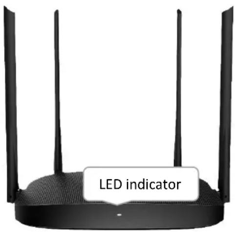
Figure 1-1 LED indicator
Table 1-1 LED indicator description
| Status | Description |
| Solid on | Starting up or connected to the internet |
| Blinking slow | No internet connection |
| Blinking fast for 2 minutes | Performing WPS negotiation |
| Blinking fast for 3 seconds | A wired device connecting to or disconnected from the router |
1.2.2 Jack, ports, and button
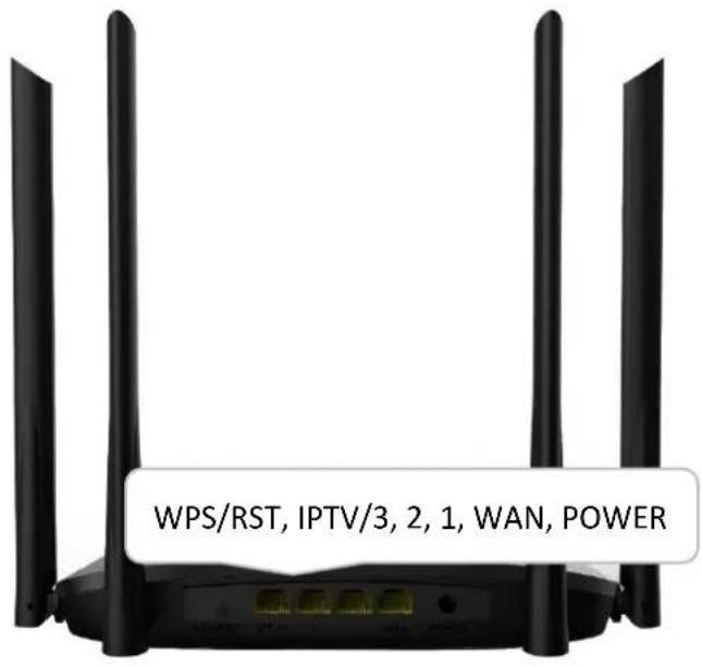
Figure 1-2 Jack, ports, and button
Table 1-2 Jack, ports and button description
| Jack/port/button | Description |
| WPS/RST | Used for WPS negotiation or reset.WPS: Press the button for 1 to 3 seconds, and enable the WPS function of the WPS-enabled device within 2 minutes to establish a WPS connection.RST: Hold down the button for about 8 seconds and then release it when the LED indicator blinks fast. The router is reset successfully. |
| IPTV/3 | 10/100 Mbps auto-negotiation Ethernet port.Used as a LAN port by default. Once the IPTV function is enabled, it can only serve as an IPTV port to connect to a set-top box. |
| 1,2 | 10/100 Mbps auto-negotiation LAN port.Used to connect devices. |
| WAN | 10/100 Mbps auto-negotiation WAN portUsed to connect to the external network. |
| POWER | Power jackUsed to power on the router (with the included power adapter). |
1.3 Label
The bottom label shows the login IP address, SSID, MAC address, serial number (SN) of the router. See the following figure.
HIKVISION®
Model: DS-3WR12GC
IP Address: 192.168.0.1
Power: 9V = 1A
SSID:
SN:
Wireless Router
Login address:
Date:
FCC ID:
MAC:
This device complies with Part 15 of the FCC Rules.
Operation is subject to the following two conditions:
(1) this device may not cause harmful interference, and
(2) this device must accept any interference received,
including interference that may cause undesired operation.
Manufacturer: Hangzhou Hikvision Digital Technology Co., Ltd.
Address: No.555 Qianmo Road, Binjiang District, Hangzhou 310052, China

MADE IN CHINA
Figure 1-3 Label
Login address: It is the domain name used to log in to the web UI of the router.
IP Address: It is the default address used to log in to the web UI of the router.
SSID: It specifies the default WiFi name of the router.
SN: It is required if you need technical assistance.
MAC: It specifies the MAC address of the router.
Chapter 2 Web UI
2.1 Log in to the web UI
Step 1 Connect your smartphone to the WiFi network of the router, or connect your computer to a LAN port of the router.
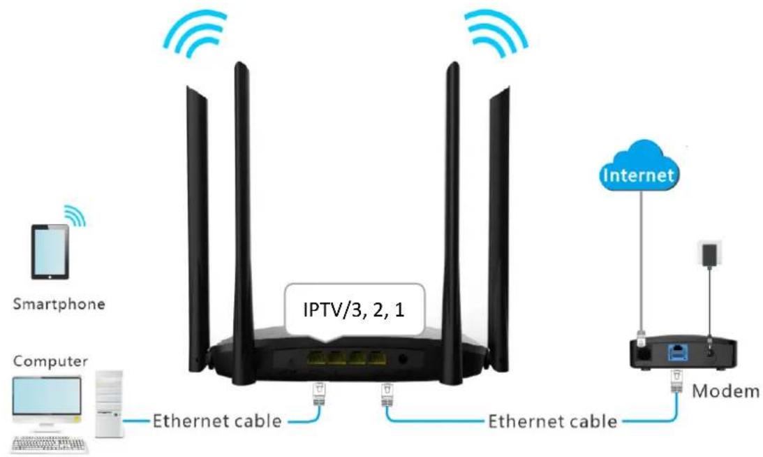
Figure 2-1 Connect your device to the router
Step 2 Launch a web browser on the device connected to the router, and visit http://hikvisionwifi.local.

Figure 2-2 Visit the domain name of the router
The following page appears.
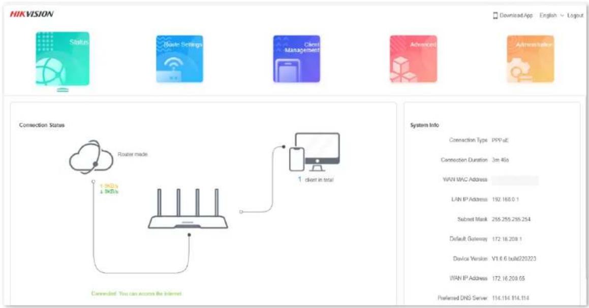
Figure 2-3 Web UI

Note
If the above page does not appear, try the following solutions:
● Ensure that the router is powered on properly.
- If you are using a computer to access the page, check whether the computer obtains an IP address automatically. Refer to A.1 Configuring the computer to obtain an IPv4 address automatically.
- If you are using a smartphone to access the page, ensure that your cellular network is disabled.
- Reset the router and log in to the web UI of the router.
2.2 Log out of the web UI
If you log in to the web UI of the router and perform no operation within 5 minutes, the router logs you out automatically. You can also log out by clicking Logout in the upper right corner of the web UI.

If there is no Logout button in the upper right corner, please set the login password first, and then enter the web UI again, the Logout button will appear in the upper right corner.
2.3 Web UI layout
The web UI of the router consists of two parts, including the navigation bar and the configuration area. See the following figure.
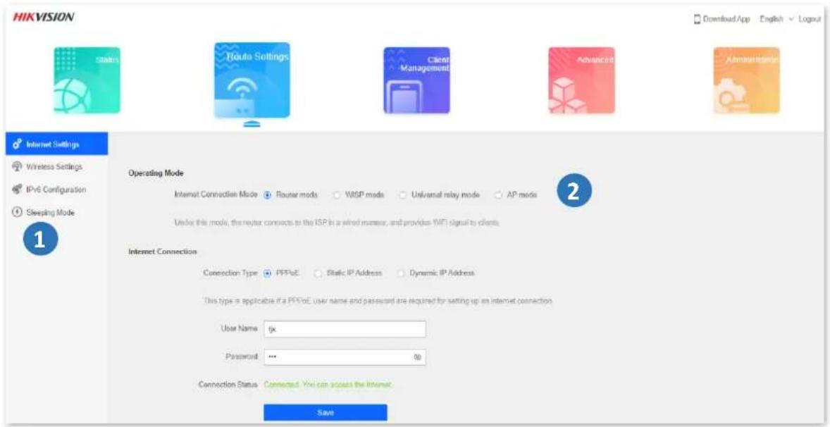
Figure 2-4 Web UI layout
i Note
The functions and parameters shown in gray indicate that the functions are not supported or cannot be modified.
Table 2-1 Navigation bar and configuration area description
| SN | Name | Description |
| 1. | Navigation bar | It is used to show the function menu of the router. Users can select functions in the navigation bar and the configuration appears in the configuration area. |
| 2 | Configuration area | It is used to modify or view your configurations. |
2.4 Common element
The common elements used on the web UI are as follows.
Table 2-2 Common element description
| Common element | Description |
| Save | It is used to save the current configurations and enable them to take effect. |
| Cancel | It is used to cancel the current configurations and restore the previous settings. |
Chapter 3 Status
Log in to the web UI of the router and choose Status to enter the page. On this page, you can:
- View internet connection status
- View online device information
- View system information
3.1 View internet connection status
You can view the internet connection status on this page.
Procedures:
Step 1 Launch a web browser on a device connected to the router and visit http://hikvisionwifi.local to log in to the web UI of the router.
Step 2 Navigate to Status > Connection Status.
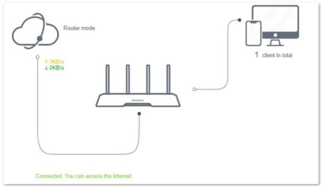
When the internet and the router are connected and Connected. You can access the internet. is shown as below, the router is connected to the internet successfully and you can access the internet through the router.
flowchart
graph TD
    A["Router mode"] -->|↑ 0KB/s ↓ 0KB/s| B["Client"]
    B --> C["1 client in total"]
    style A fill:#f9f,stroke:#333
    style B fill:#ccf,stroke:#333
    style C fill:#cfc,stroke:#333
Figure 3-1 Internet connection status
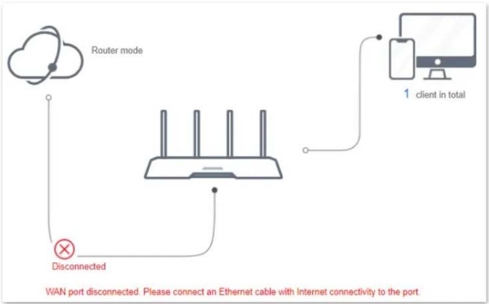
When a red cross and “Disconnected” are shown between the internet and the router, and WAN port disconnected. Please connect an Ethernet cable with Internet connectivity to the port. is shown on the page, it indicates that the Ethernet cable is not connected properly. Please ensure that the Ethernet cable is connected properly.
flowchart
graph TD
    A["Router mode"] --> B["WiN port"]
    B --> C["Wireless Router"]
    C --> D["Client in total"]
    D --> E["1 client in total"]
    F["Disconnected"] --> C
Figure 3-2 Internet connection status
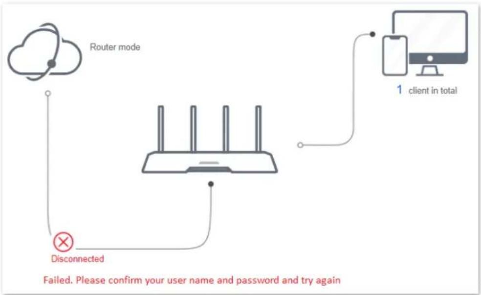
When a red cross and "Disconnected" are shown between the internet and the router, and Failed. Please confirm your user name and password and try again. is shown on the page, it indicates that the user name and password you entered were incorrect. Please navigate to the Internet Settings page to try again.
flowchart
graph TD
    A["Router mode"] --> B["Wireless Router"]
    B --> C["Client 1: client in total"]
    B --> D["Disconnected"]
    D --> E["Failed. Please confirm your user name and password and try again"]
Figure 3-3 Internet connection status
i Note
Please consider the following tips when entering the username and password:
● Pay attention to case sensitivity, such as "Z" and "z".
● Pay attention to similar letters and numbers, such as "I" and "1".
- Ensure the completeness of account parameters, such as "0755000513@163.gd", rather than "0755000513"
If the problem persists, contact your ISP.
When a red cross and "Disconnected" are shown between the internet and the router, and Error: No response from the remote server. Please contact your ISP. is shown on the page, try the following solutions:
- Ensure that the Ethernet cable is connected properly.
- Ensure that you choose the proper connection type (Contact your ISP for any doubt about the connection type).
- Power off the router and wait for several minutes, then power it on and try again. If the problem persists, consult your ISP.
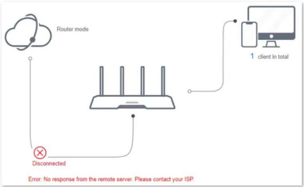
flowchart
graph TD
    A["Router mode"] --> B["Wireless Router"]
    B --> C["Client 1: client in total"]
    B --> D["Disconnected"]
    D --> E["Error: No response from the remote server. Please contact your ISP."]
Figure 3-4 Internet connection status
When a red cross and "Disconnected" are shown between the internet and the router, and Dial-up connection succeeded but the internet is inaccessible. Please contact your ISP. is shown on the page, contact your ISP for the problem.
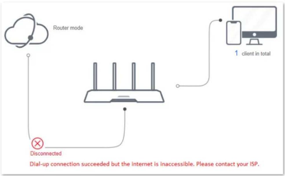
flowchart
graph TD
    A["Router mode"] --> B["Client 1: client in total"]
    B --> C["Switch: Switched to Dial-up connection"]
    C --> D["Switch: Switched to dial-up connection"]
    D --> E["Switch: Switched to dial-up connection"]
    E --> F["Switch: Switched to dial-up connection"]
    F --> G["Switch: Switched to dial-up connection"]
    G --> H["Switch: Switched to dial-up connection"]
    H --> I["Switch: Switched to dial-up connection"]
    I --> J["Switch: Switched to dial-up connection"]
    J --> K["Switch: Switched to dial-up connection"]
    K --> L["Switch: Switched to dial-up connection"]
    L --> M["Switch: Switched to dial-up connection"]
    M --> N["Switch: Switched to dial-up connection"]
    N --> O["Switch: Switched to dial-up connection"]
    O --> P["Switch: Switched to dial-up connection"]
    P --> Q["Switch: Switched to dial-up connection"]
    Q --> R["Switch: Switched to dial-up connection"]
    R --> S["Switch: Switched to dial-up connection"]
    S --> T["Switch: Switched to dial-up connection"]
    T --> U["Switch: Switched to dial-up connection"]
    U --> V["Switch: Switched to dial-up connection"]
    V --> W["Switch: Switched to dial-up connection"]
    W --> X["Switch: Switched to dial-up connection"]
    X --> Y["Switch: Switched to dial-up connection"]
    Y --> Z["Switch: Switched to dial-up connection"]
    Z --> AA["Switch: Switched to dial-up connection"]
    AA --> AB["Switch: Switched to dial-up connection"]
    AB --> AC["Switch: Switched to dial-up connection"]
    AC --> AD["Switch: Switched to dial-up connection"]
    AD --> AE["Switch: Switched to dial-up connection"]
    AE --> AF["Switch: Switched to dial-up connection"]
    AF --> AG["Switch: Switched to dial-up connection"]
    AG --> AH["Switch: Switched to dial-up connection"]
    AH --> AI["Switch: Switched to dial-up connection"]
    AI --> AJ["Switch: Switched to dial-up connection"]
    AJ --> AK["Switch: Switched to dial-up connection"]
    AK --> AL["Switch: Switched to dial-up connection"]
    AL --> AM["Switch: Switched to dial-up connection"]
    AM --> AN["Switch: Switched to dial-up connection"]
    AN --> AO["Switch: Switched to dial-up connection"]
    AO --> AP["Switch: Switched to dial-up connection"]
    AP --> AQ["Switch: Switched to dial-up connection"]
    AQ --> AR["Switch: Switched to dial-up connection"]
    AR --> AS["Switch: Switched to dial-up connection"]
    AS --> AT["Switch: Switched to dial-up connection"]
    AT --> AU["Switch: Switched to dial-up connection"]
    AU --> AV["Switch: Switched to dial-up connection"]
    AV --> AW["Switch: Switched to dial-up connection"]
    AW --> AX["Switch: Switched to dial-up connection"]
    AX --> AY["Switch: Switched to dial-up connection"]
Figure 3-5 Internet connection status
When a red cross and "Disconnected" are shown between the internet and the router, and The router has obtained a valid IP address but cannot access the Internet. Please try the solutions below one by one. is shown as below, follow the instructions on the page to solve the problem.
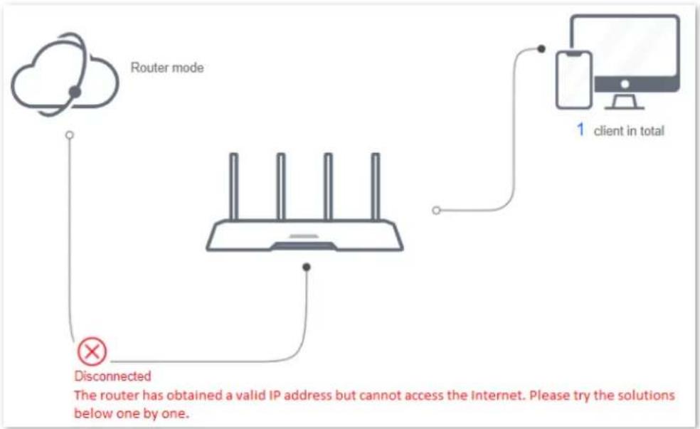
flowchart
graph TD
    A["Router mode"] --> B["IP Address"]
    B --> C["Client 1: client in total"]
    C --> D["Disconnected"]
    D --> E["The router has obtained a valid IP address but cannot access the Internet. Please try the solutions below one by one."]
Figure 3-6 Internet connection status
3.2 View online device information
This part shows the information of online devices, such as the number and real-time upload/download speed.
To access the page, log in to the web UI of the router and navigate to Status > (Online devices).
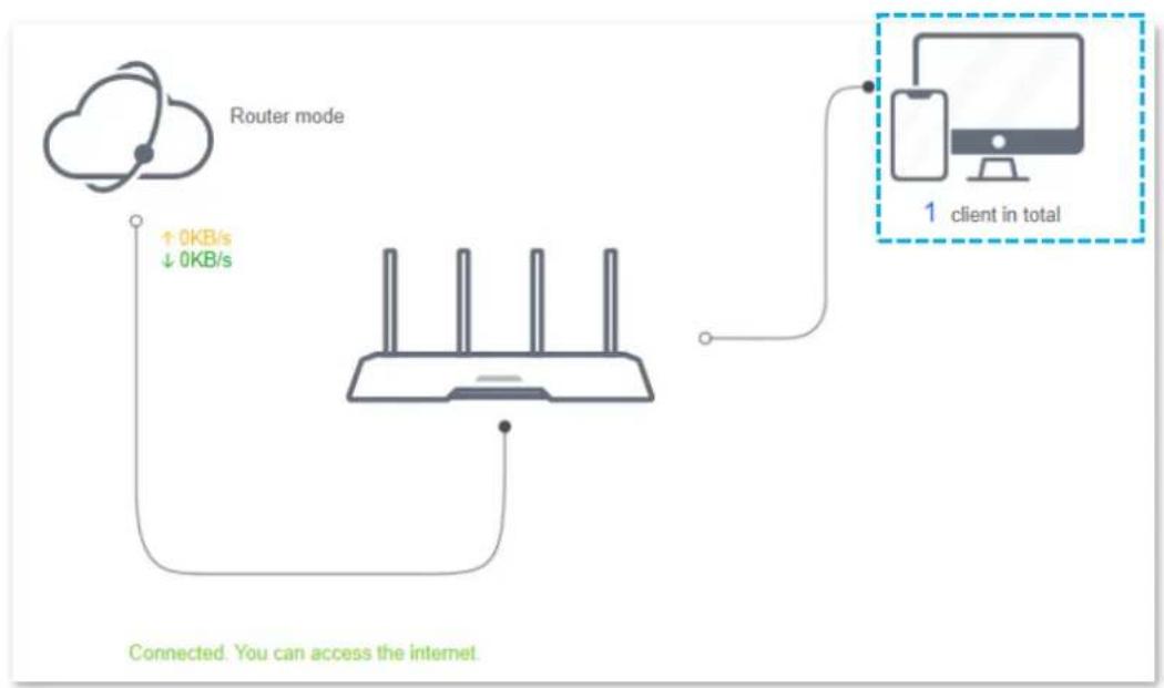
flowchart
graph TD
    A["Router mode"] -->|↑ 0KB/s ↓ 0KB/s| B["Router"]
    B --> C["Client in total"]
    C --> D["1 client in total"]
    style A fill:#f9f,stroke:#333
    style B fill:#ccf,stroke:#333
    style C fill:#cfc,stroke:#333
    style D fill:#fcc,stroke:#333
Figure 3-7 Online device information
To control the bandwidth of online devices, click the Download Speed and Upload Speed area to enter the Access Control page.
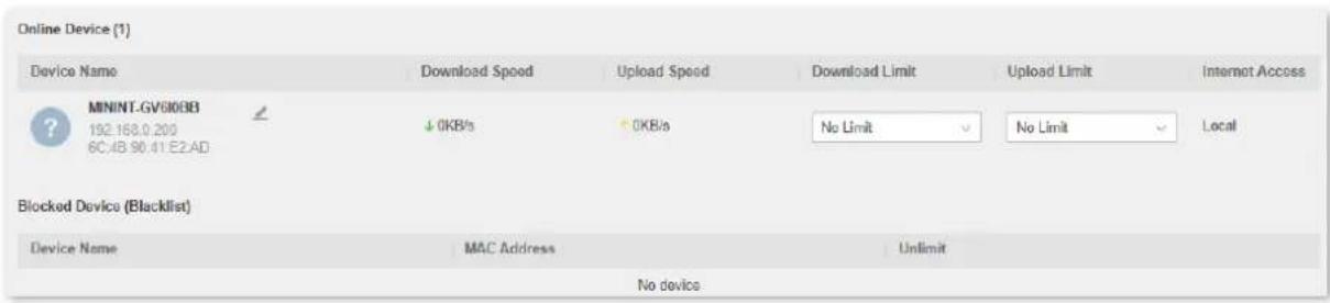
Figure 3-8 Online device information
3.3 View system information
This section shows the basic information of the router, including connection type, connection duration, WAN IP address and so on.
To access the page, log in to the web UI of the router and navigate to Status > System Info.
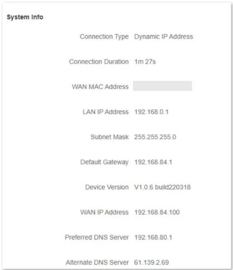
network
System Info | Category | Description | | :--- | :--- | | Connection Type | Dynamic IP Address | | Connection Duration | 1m 27s | | WAN MAC Address | | LAN IP Address | 192.168.0.1 | | Subnet Mask | 255.255.255.0 | | Default Gateway | 192.168.84.1 | | Device Version | V1.0.6 build220318 | | WAN IP Address | 192.168.84.100 | | Preferred DNS Server | 192.168.80.1 | | Alternate DNS Server | 61.139.2.69 |Figure 3-9 System information
Table 3-1 System information parameter description
| Parameter | Description |
| Connection Type | It shows the current IPv4 connection type of the router. |
| Connection Duration | It specifies the time that has elapsed since the router connects to the IPv4 internet successfully. |
| WAN MAC Address | It specifies the MAC address of the WAN port of the router. |
| LAN IP Address | It specifies the IP address of the LAN port for the router. LAN users can access the web UI of the router by visiting this IP address(default: 192.168.0.1). |
| Subnet Mask | It specifies the subnet mask of the WAN port. |
| Default Gateway | It specifies the IPv4 default gateway of the router. |
| Device Version | It specifies the current version number of the router's firmware. |
| WAN IP Address | It specifies the IPv4 address of the WAN port. |
| Preferred DNS Server | They show the preferred and alternative IPv4 DNS server address of the WAN port. |
| Alternate DNS Server |
Chapter 4 Route settings
4.1 Internet settings
4.1.1 Overview
On this page, you can complete the internet settings to achieve the shared internet access for multiple users.
To access the page, log in to the web UI of the router and navigate to Route Settings > Internet Settings.
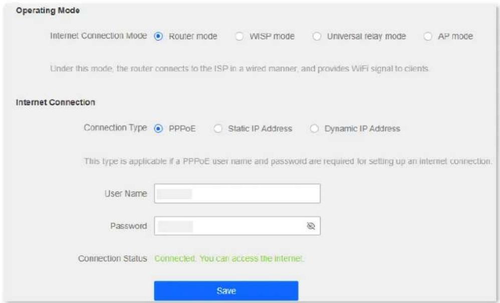
Figure 4-1 Internet settings
The router supports multiple working modes, including router mode, WISP mode, universal relay mode and AP mode. Choose the suitable mode according to your context of use.
Table 4-1 Working mode of the router
| Context of use | Suitable mode |
| Connect your router to a modem or Ethernet jack using an Ethernet cable. | Router mode |
| Bridge the existing WiFi network and extend the wireless coverage. | WISP mode or Universal relay mode |
| Connect the router to a smart home gateway to provide wireless coverage. | AP mode |
4.1.2 Serve as a router
If you use the router for the first time or the router is restored to factory settings, follow the quick installation guide to configure the internet access. If you want to modify internet parameters or other settings, you can follow the instruction in this chapter.
By default, the router works in router mode. Under this mode, connect the WAN port of the router to the internet, connect the LAN ports to user devices and complete the internet settings, then you can access the internet on these devices.

Note
Parameters are provided by your ISP. Contact your ISP for any doubts.
Set up a PPPoE connection
If the ISP provides you with a PPPoE user name and password, you can choose this connection type to access the internet. The application scenario is shown below.
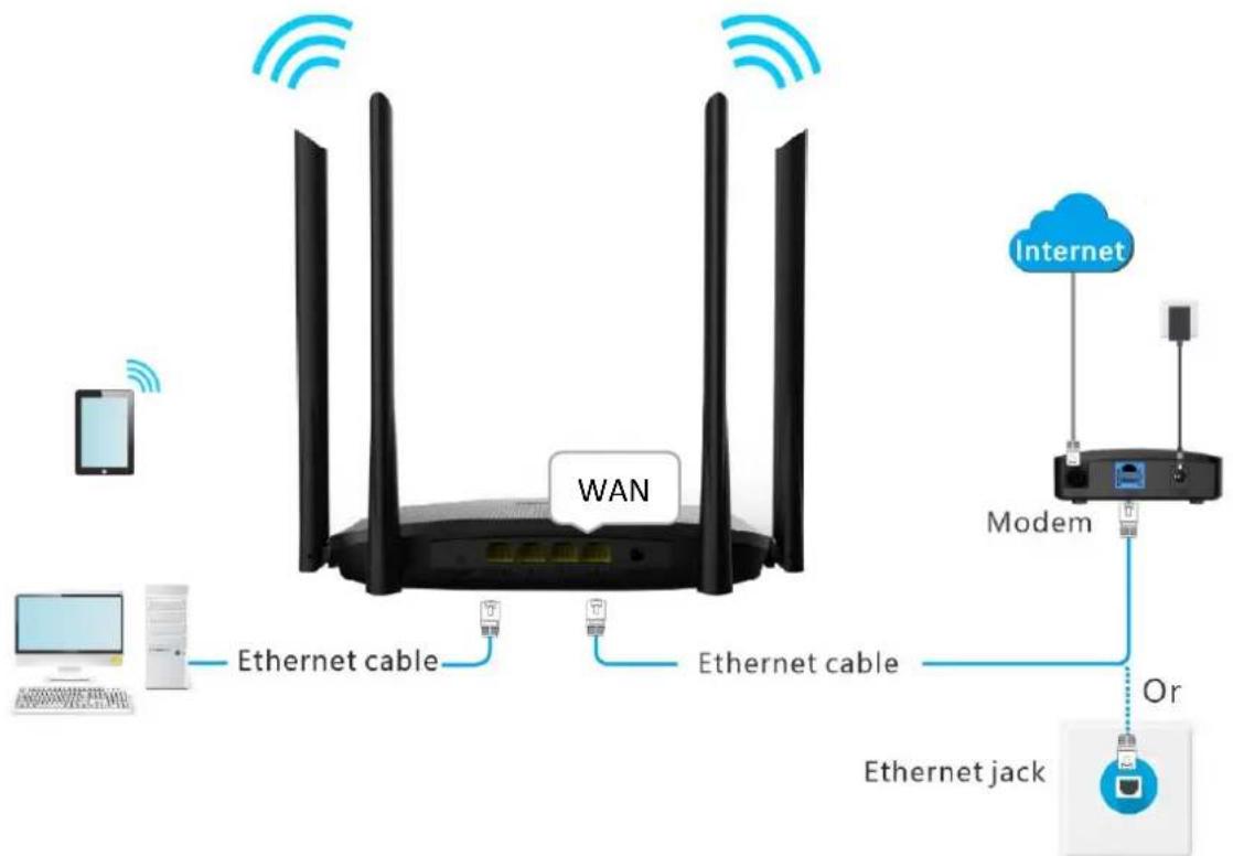
flowchart
graph TD
    A["WiWAN"] -->|Ethernet cable| B["Modem"]
    B -->|Or| C["Ethernet jack"]
    D["Internet"] -->|Ethernet cable| B
    E["Desktop"] -->|Ethernet cable| B
    F["Computer"] -->|Ethernet cable| B
Figure 4-2 Application scenario
Procedures:
Step 1 Launch a web browser on a device connected to the router and visit http://hikvisionwifi.local to log in to the web UI of the router.
Step 2 Navigate to Route Settings > Internet Settings.
Step 3 Set Operating Mode to Router Mode.
Step 4 Set Connection Type to PPPoE.
Step 5 Enter the User Name and Password provided by your ISP.
Step 6 Click Save at the bottom of the page.
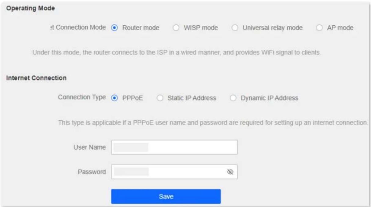
Figure 4-3 Set up a PPPoE connection
Wait a moment. When "Connected. You can assess the internet." is shown on the page, the router is connected to the internet.
Internet Connection
Connection Type ● PPPoE ○ Static IP Address ○ Dynamic IP Address
This type is applicable if a PPPoE user name and password are required for setting up an internet connection.
User Name
Password

Connection Status Connected. You can access the internet
Figure 4-4 Connection status

Note
If you still cannot access the internet, try the following solutions:
- If "Error: No response from the remote server. Please contact your ISP." is shown on the page, you are recommended to set the Connection Type to Dynamic IP Address.
- If the problem persists, refer to 3.1 View internet connection status to find a solution.
Table 4-2 PPPoE parameter description
| Parameter | Description |
| User Name | They specify the PPPoE user name and password provided by your ISP. |
| Password | |
| Connection Status | It specifies the connection status of the WAN port.When “Connected. You can access the internet now.” is shown here, the router is connected to the internet successfully.When other information is shown here, the router fails to connect to the internet. Please take corresponding measures according to the information shown here. |
Set up a static IP connection
When your ISP provides you with information including IP address, subnet mask, default gateway and DNS server, you can choose this connection type to access the internet.
Procedures:
Step 1 Launch a web browser on a device connected to the router and visit http://hikvisionwifi.local to log in to the web UI of the router.
Step 2 Navigate to Route Settings > Internet Settings.
Step 3 Set Connection Type to Static IP Address.
Step 4 Set the required parameters provided by your ISP.
Step 5 Click Save at the bottom of the page.
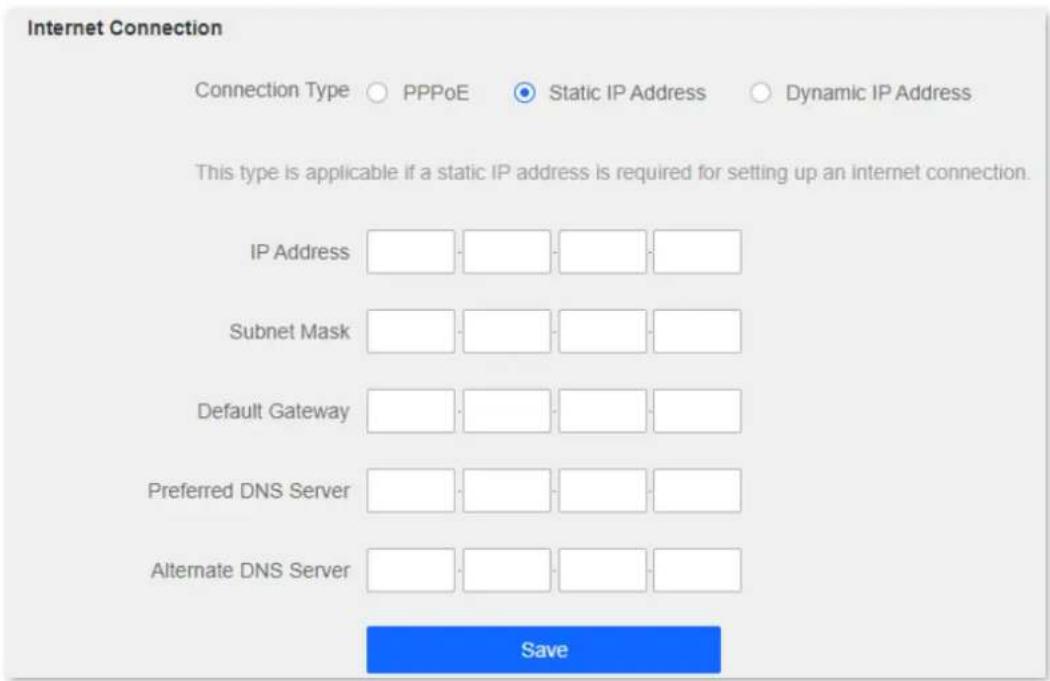
Figure 4-5 Set up a static IP connection
Wait a moment. When "Connected. You can access the internet." is shown on the page, you can access the internet.
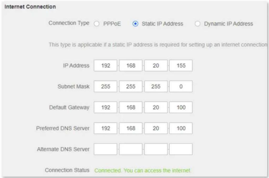
other
Internet Connection | Connection Type | PPPoE | Static IP Address | Dynamic IP Address | | :--- | :--- | :--- | :--- | | IP Address | 192 | 168 | 20 | | Subnet Mask | 255 | 255 | 0 | | Default Gateway | 192 | 168 | 20 | | Preferred DNS Server | 192 | 168 | 20 | | Alternate DNS Server | | | | This type is applicable if a static IP address is required for setting up an internet connection. Connection Status Connected. You can access the internet.Figure 4-6 Connection status
If you still cannot access the internet, refer to 3.1 View internet connection status to find a solution.
Table 4-3 Static IP address parameter description
| Parameter | Description |
| IP Address | When the static IP address is chosen as the connection type, enter the fixed IP address information provided by your ISP. |
| Subnet Mask | |
| Default Gateway |  If your ISP only provides one DNS server address, you can leave the Alternate DNS blank. If your ISP only provides one DNS server address, you can leave the Alternate DNS blank. |
| Preferred DNS | |
| Alternate DNS | |
| Connection Status | It specifies the connection status of the WAN port.When “Connected. You can access the internet now.” is shown here, the router is connected to the internet successfully.When other information is shown here, the router fails to connect to the internet. Please take corresponding measures according to the information shown here. |
Set up a dynamic IP connection
Generally, accessing the internet through a dynamic IP address is applicable in the following situations:
- Your ISP does not provide PPPoE user name and password, or any information including IP address, subnet mask, default gateway and DNS server.
- You have a router with internet access and want to add another router.
The application scenario is shown below.
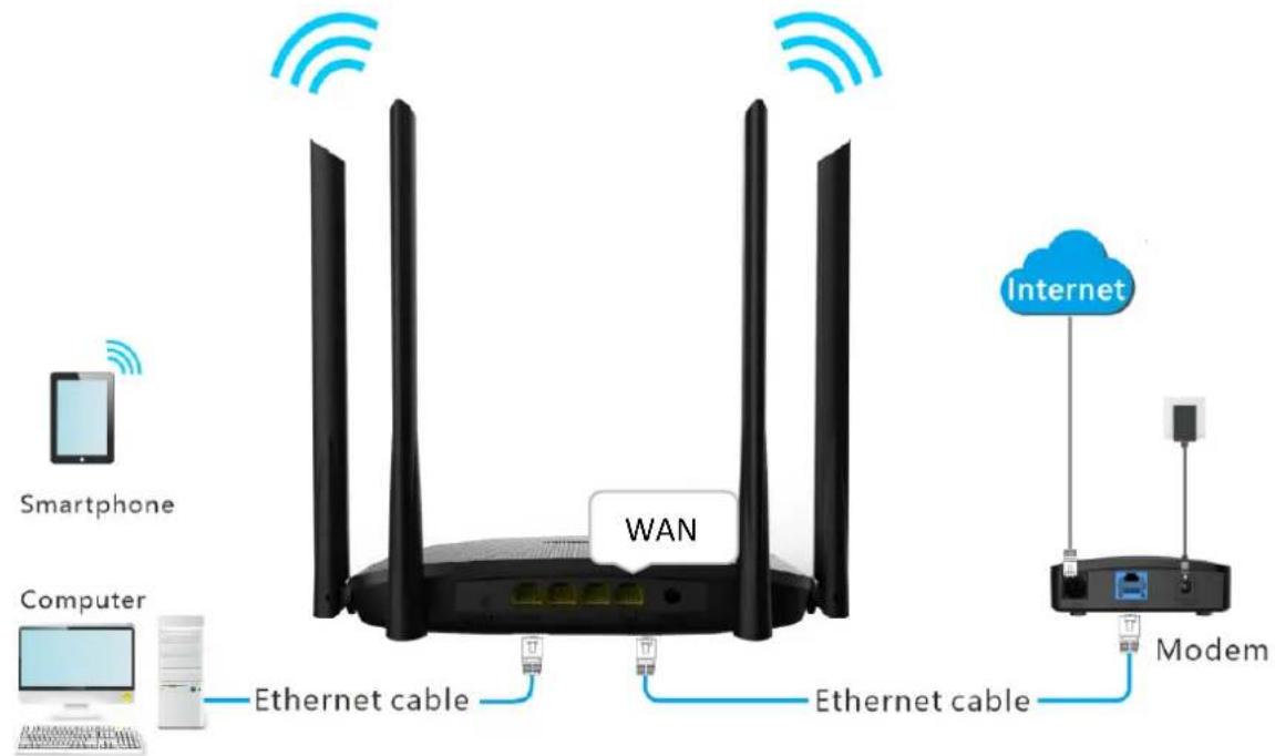
Figure 4-7 Application scenario
Procedures:
Step 1 Launch a web browser on a device connected to the router and visit http://hikvisionwifi.local to log in to the web UI of the router.
Step 2 Navigate to Route Settings > Internet Settings.
Step 3 Set Operating Mode to Router Mode.
Step 4 Set Connection Type to Dynamic IP Address.
Step 5 Click Save at the bottom of the page.
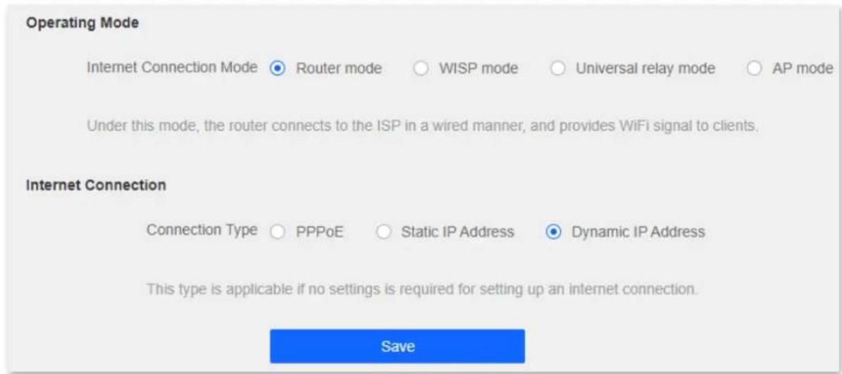
Figure 4-8 Set up a dynamic IP connection
Wait a moment. When "Connected. You can access the internet." is shown on the page, you can access the internet.
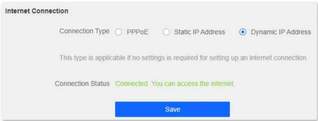
Figure 4-9 Connection status
If you still cannot access the internet, refer to 3.1 View internet connection status to find a solution.
4.1.3 Serve as a WiFi extender
If you have a router that is connected to the internet and wants to extend the WiFi coverage, you can refer to this chapter.
Assume that the information about your existing WiFi network is as follows:
- WiFi name: My_home_WiFi
- WiFi password: Hikvision123456
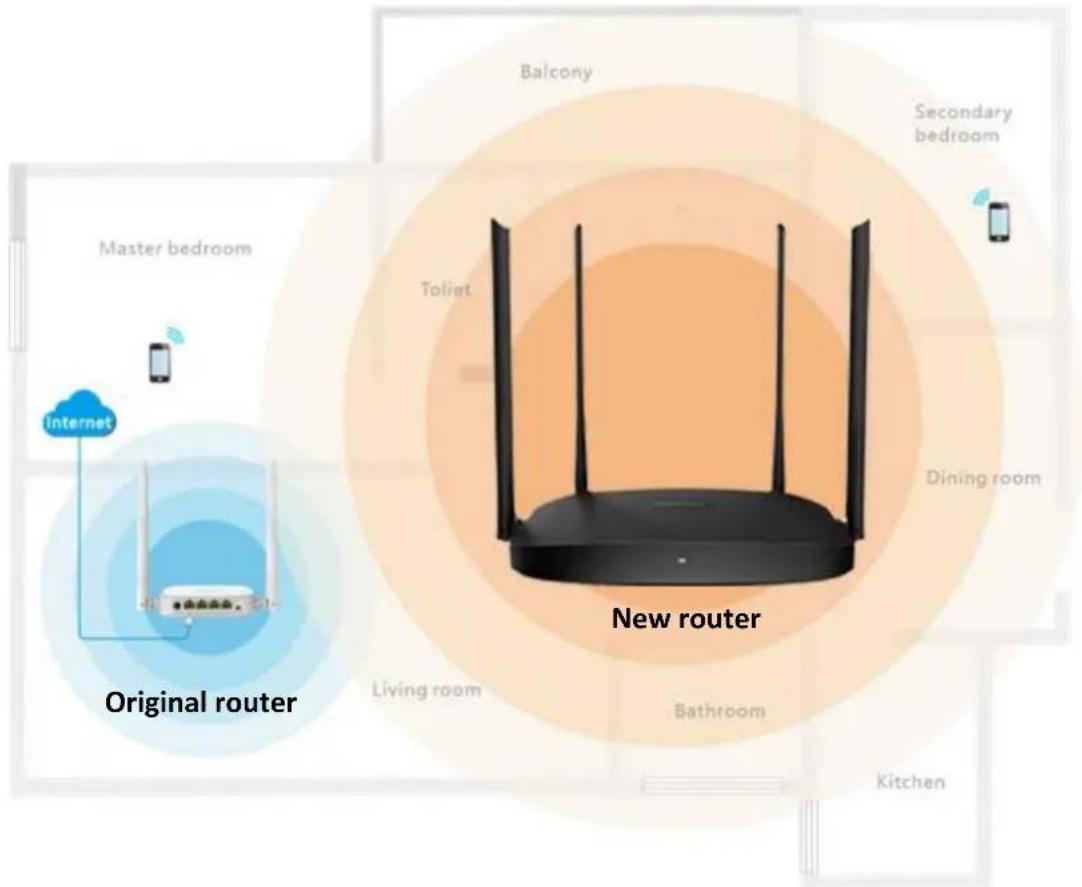
Figure 4-10 Application scenario
Method 1: Set the router to WISP mode
Procedures:
Step 1 Launch a web browser on a device connected to the router and visit http://hikvisionwifi.local to log in to the web UI of the router.
i Note
If you use the router for the first time or have reset the router, proceed with the following steps. If you have already configured the router, skip Step 2.
Step 2 Set Connection Type to Dynamic IP Address, and click Save. You will be directed to the Status page.
i Note
If you are using a wireless device for configuration and are not directed to the Status page automatically, ensure that your wireless device is still connected to the WiFi network of the router.
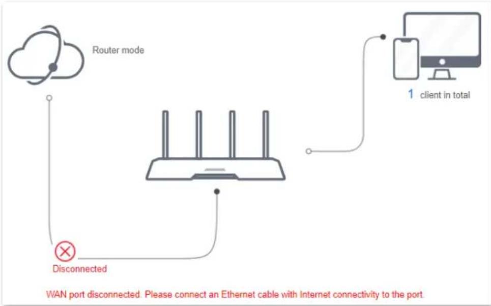
flowchart
graph TD
    A["Router mode"] --> B["Wireless Router"]
    B --> C["Client 1: client in total"]
    B --> D["Disconnected"]
    D --> E["WAN port disconnected. Please connect an Ethernet cable with Internet connectivity to the port"]
Figure 4-11 Internet connection status
Step 3 Navigate to Route Settings > Internet Settings > Operating Mode.
Step 4 Set Operating Mode to WISP.
Step 5 Select the ISP hotspot, which is My_home_WiFi in this example.
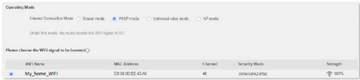
Figure 4-12 Select the WiFi signal to be boosted
Step 6 Enter the password of the WiFi network, which is Hikvision123456 in this example.
Step 7 Click OK. The router will reboot to activate the settings.
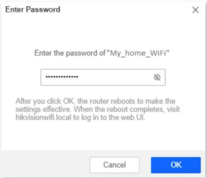
Figure 4-13 Enter password
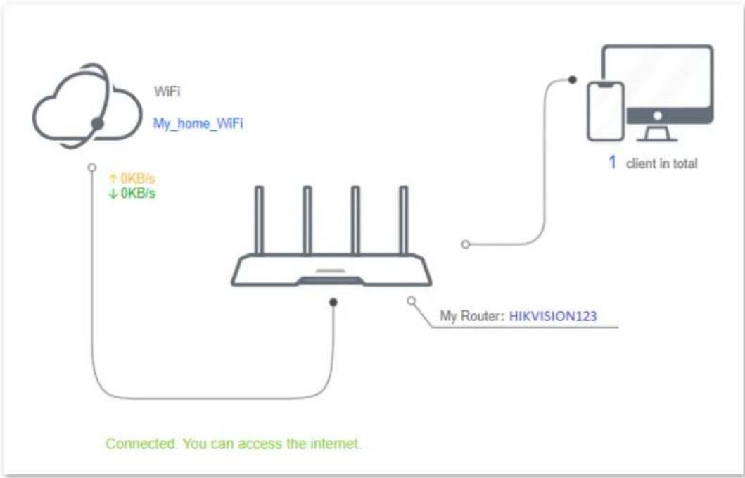
Step 8 Log in to the web UI of the router again, navigate to Status > Connection Status to ensure that Connected. You can access the internet. is shown on this page.
flowchart
graph TD
    A["Cloud with WiFi"] -->|↑0KB/s ↓0KB/s| B["Router"]
    C["My_home_WiFi"] -->|0KB/s| B
    D["Client 1: client in total"] --> E["Router"]
    F["My Router: HIKVISION123"] --> B
    G["Connected. You can access the internet."] --> B
Figure 4-14 Connection status

Note
If the connection between WiFi and My Router failed, try the following solutions:
- Ensure that you have entered the correct WiFi password of the WiFi, and mind case sensitivity.
- Ensure that My Router is within the wireless coverage of the WiFi.
Step 9 Relocate the new router by referring to the following suggestions and power it on again:
- Between the original router and the uncovered area, but within the coverage of the original router.
- Away from the microwave oven, electromagnetic oven or refrigerator.
- Above the ground with few obstacles.

Caution
Do not connect any device to the WAN port of the new router after setting the router to WISP mode.
To access the internet, connect your computer to a LAN port of the new router, or connect your smartphone to the WiFi network of the new router.
Navigate to Route Settings > Wireless Settings > WiFi Name and Password to check the WiFi name and password. If the network is not encrypted, you can also set a WiFi password on this page for security.
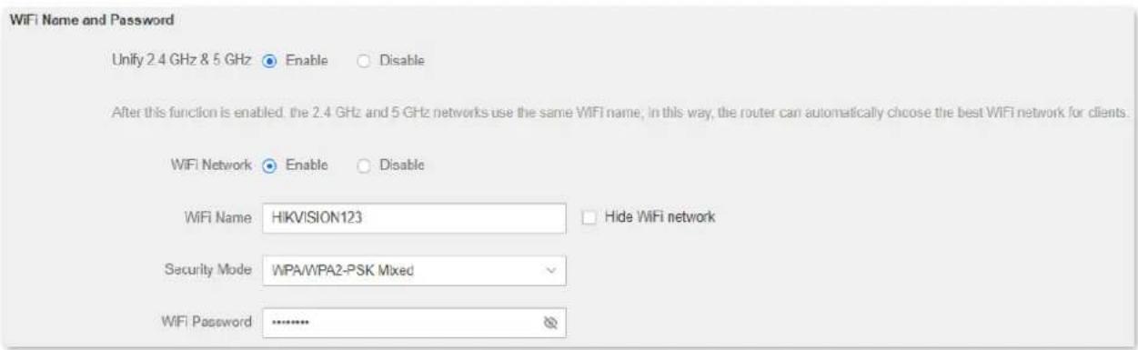
Figure 4-15 WiFi name and password
i Note
If you cannot access the internet, try the following solutions:
- Ensure that the existing router is connected to the internet successfully.
- Ensure that your wireless devices are connected to the WiFi network of the new router.
- If the computer connected to the router for repeating cannot access the internet, ensure that the computer is configured to obtain an IP address and DNS sever automatically.
Method 2: Set the router to universal relay mode
Procedures:
Step 1 Launch a web browser on a device connected to the router and visit http://hikvisionwifi.local to log in to the web UI of the router.

Note
If you use the router for the first time or have reset the router, proceed with the following steps. If you have already configured the router, skip Step 2.
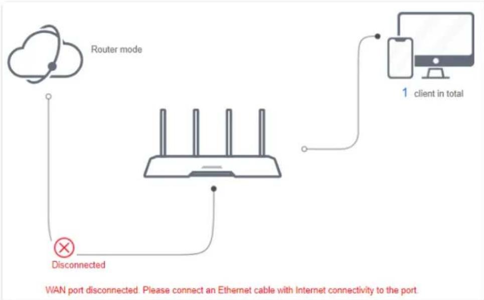
Step 2 Set Connection Type to Dynamic IP Address, and click Save. You will be directed to the Status page.

Note
If you are using a wireless device for configuration and are not directed to the Status page automatically, ensure that your wireless device is still connected to the WiFi network of the router.
flowchart
graph TD
    A["Router mode"] --> B["Wi-Fi Router"]
    B --> C["Client 1: client in total"]
    B --> D["Disconnected"]
    D --> E["Wi-Fi Portugal"]
Figure 4-16 Internet connection status
Step 3 Navigate to Route Settings > Internet Settings > Operating Mode.
Step 4 Set Operating Mode to Universal relay mode.
Step 5 Select the ISP hotspot, which is My_home_WiFi in this example.
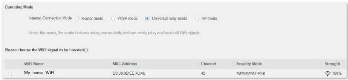
Figure 4-17 Select the ISP hotspot to be boosted
Step 6 Enter the password of the selected WiFi network, which is Hikvision123456 in this example.
Step 7 Click OK. The router will reboot to activate the settings.
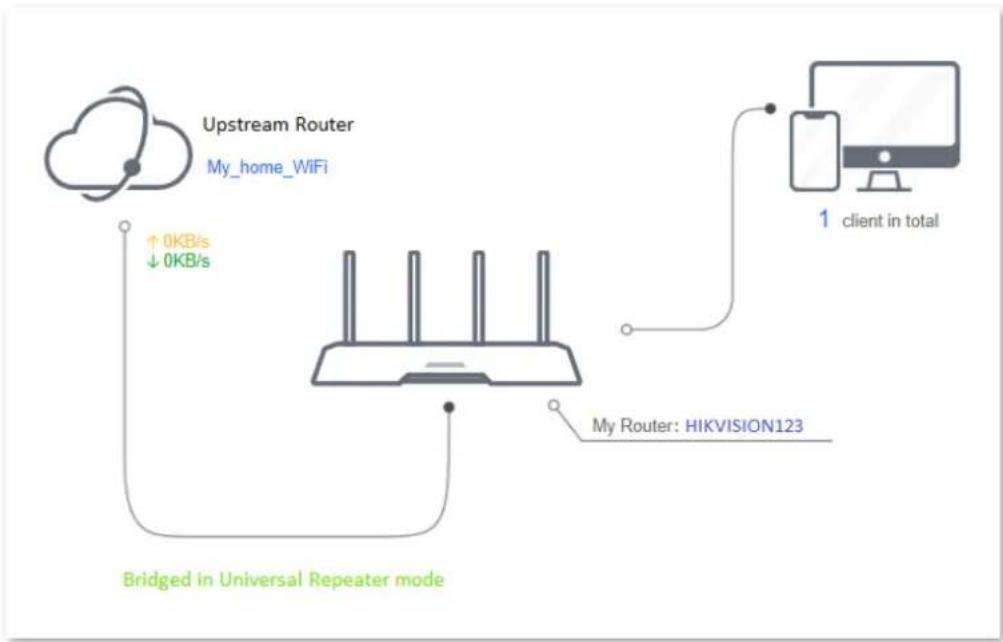
Step 8 Log in to the web UI of the router again, navigate to Status > Connection Status to ensure that Bridged in Universal Repeater mode is shown on this page.
i Note
The LAN IP address of the router will change. Please log in to the web UI of the router by visiting http://hikvisionwifi.local. If there is another network device with the same login domain name (hikvisionwifi.local) as the router, log in to the upstream router and find the IP address obtained by the new router in the client list. Then you can log in to the web UI of the router by visiting the IP address.
flowchart
graph TD
    A["Upstream Router\nMy_home_WiFi"] -->|0KB/s ↓ 0KB/s| B["Bridged in Universal Repeater mode"]
    C["My Router: HIKVISION123"] -->|1 client in total| D
Figure 4-18 Connection status
i Note
If the connection between the Upstream Router and My Router failed, try the following solutions:
- Ensure that you have entered the correct WiFi password of the WiFi, and mind case sensitivity.
- Ensure that My Router is within the wireless coverage of the Upstream Router.
Step 9 Relocate the new router by referring to the following suggestions and power it on again:
Between the original router and the uncovered area, but within the coverage of the original router.
- Away from the microwave oven, electromagnetic oven, refrigerator.
- Above the ground with few obstacles.
Caution
After the new router is set to universal relay mode, Do NOT connect any device to the WAN port of the new router.
To access the internet, connect your computer to a LAN port of the new router, or connect your smartphone to the WiFi network of the new router.
Navigate to Wireless Settings > WiFi Name and Password to check the WiFi name and password. If the network is not encrypted, you can also set a WiFi password on this page for security.
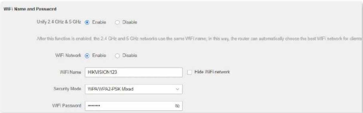
Figure 4-19 WiFi name and password
i Note
If you cannot access the internet, try the following solutions:
- Ensure that the existing router is connected to the internet successfully.
- Ensure that your wireless devices are connected to the WiFi network of the new router.
- If the computer connected to the router for repeating cannot access the internet, ensure that the computer is configured to obtain an IP address and DNS sever automatically.
4.1.4 Serve as an AP
When you have a smart home gateway that only provides wired internet access, you can set the router to work in AP mode to provide wireless coverage.
i Note
When the router is set to AP mode:
● Every physical port can be used as a LAN port.
- The LAN IP address of the router will be changed. Please log in to the web UI of the router by visiting http://hikvisionwifi.local.
● Functions, such as bandwidth control and port mapping will be unavailable. Refer to the web UI for available functions.
Procedures:
Step 1 Power on the router. Connect a computer to a LAN port of the router, or connect your smartphone to the WiFi network of the router.
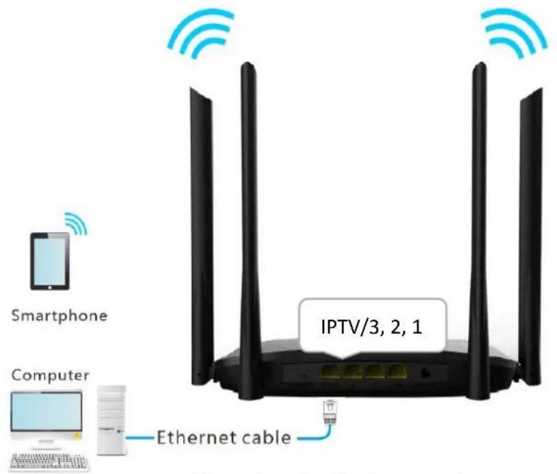
Figure 4-20 Application scenario
i Note
If you have finished the quick setup wizard before, launch a web browser and visit http://hikvisionwifi.local and skip Step 2.
Step 2 Log in to the web UI of the router.
1) Launch a web browser on a device connected to the router and visit http://hikvisionwifi.local to log in to the web UI of the router. A computer is used for the illustration below.
2) Set Connection Type to Dynamic IP Address, and click Save. You will be directed to the Status page.

Note
If you are using a wireless device for configuration and are not directed to the Status page automatically, ensure that your wireless device is still connected to the WiFi network of the router.
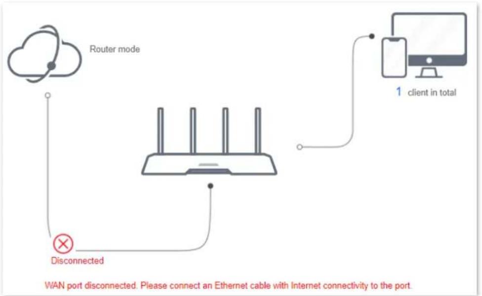
flowchart
graph TD
    A["Router mode"] --> B["WiN port"]
    B --> C["Wireless Router"]
    C --> D["Client in total"]
    D --> E["1 client in total"]
    F["× Disconnected"] --> C
Figure 4-21 Connection status
Step 3 Set the router to AP mode.
1) Navigate to Route Settings > Internet Settings > Operating Mode.
2) Set Operating Mode to AP, and click Save at the bottom of the page.

Figure 4-22 Set the router to AP mode
3) Click OK in the popup window. The router will reboot to activate the settings.
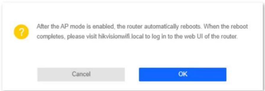
Figure 4-23 Click OK
Step 4 Connect the upstream device, such as a gateway, to any port of the router.
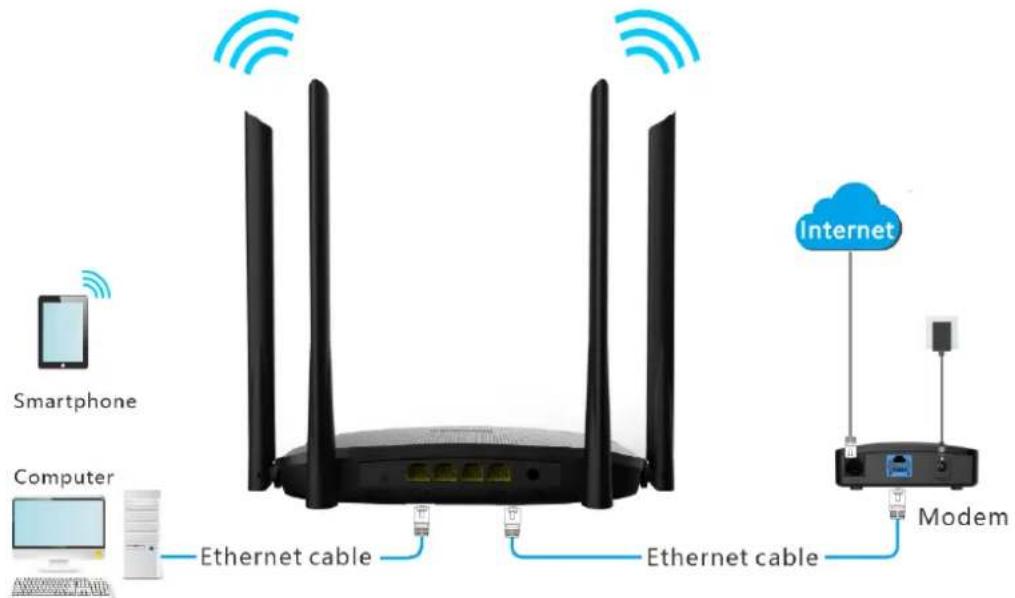
Figure 4-24 Application scenario
Log in to the web UI of the router again, and navigate to Status > Connection Status to check if the AP mode is configured successfully as follows.
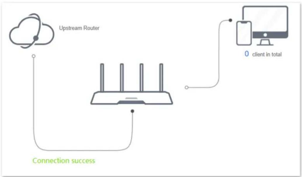
flowchart
graph TD
    A["Upstream Router"] --> B["Client"]
    B --> C["0 client in total"]
    D["Connection success"] --> A
    D --> B
Figure 4-25 Internet connection status
i Note
If there is another network device with the same login domain name (hikvisionwifi.local) as the router, log in to the upstream router and find the IP address obtained by the new router in the client list. Then you can log in to the web UI of the router by visiting the IP address.
To access the internet, connect your computer to a physical port, or connect your smartphone to the WiFi network.
Navigate to Route Settings > Wireless Settings > WiFi Name and Password to check the WiFi name and password. If the network is not encrypted, you can also set a WiFi password on this page for security.
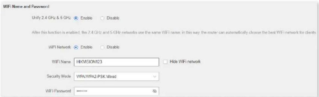
Figure 4-26 WiFi name and password

Note
If you cannot access the internet, try the following solutions:
- Ensure that the existing router is connected to the internet successfully.
- Ensure that your wireless devices are connected to the correct WiFi network of the new router.
- If the computer connected to the router cannot access the internet, ensure that the computer is configured to obtain an IP address and DNS sever automatically.
4.2 Wireless settings
4.2.1 WiFi name and password
Overview
On this page, you can configure basic WiFi parameters, such as the WiFi name and password.
To access the configuration page, log in to the web UI of the router, and navigate to Route Settings > Wireless Settings > WiFi Name and Password.
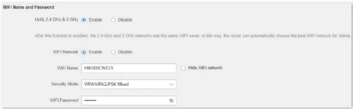
Figure 4-27 WiFi name and password
Table 4-4 WiFi name and password parameter description
| Parameter | Description |
| Unify 2.4 GHz & 5 GHz | It is used to turn on or off the Preferred Band function.When it is enabled, the WiFi names of 2.4 GHz and 5 GHz networks are integrated, and only one WiFi signal is shown. Devices connected to the WiFi network will use the network with better connection quality automatically. |
| WiFi Network | It is used to enable or disable the WiFi networks of the router. |
| 2.4 GHz Network | You can enable or disable the 2.4 GHz network and 5 GHz network separately when the Unify 2.4 GHz & 5 GHz function is disabled.If wireless devices such as mobile phones are far away from the router or blocked from the router by a wall, it is recommended to connect to the 2.4 GHz network.If the wireless devices are close to the router, it is recommended to connect to the 5 GHz network. |
| 5 GHz Network | |
| WiFi Name | It specifies the WiFi network name (SSID) of the WiFi network. |
| Security Mode | It specifies the encryption modes supported by the router, including:None: It indicates that a WiFi network is not encrypted and any clients can access the network without a password. This option is not recommended as it leads to low network security.WPA-PSK: It indicates that WPA-PSK is adopted to authenticate users.WPA2-PSK: It indicates that WPA2-PSK is adopted to authenticate users.WPA/WPA2-PSK Mixed: It indicates that WPA-PSK and WPA2-PSK are adopted to authenticate users. |
| WiFi Password | It specifies the password for connecting to the WiFi network. You are strongly recommended to set a WiFi password for security. It is recommended to use the combination of numbers, uppercase letters, lowercase letters and special symbols in the password to enhance the security of the WiFi network. It is recommended to use the combination of numbers, uppercase letters, lowercase letters and special symbols in the password to enhance the security of the WiFi network. |
| Hide WiFi | With this function enabled, wireless clients cannot find the SSID, and you need to enter the SSID on the wireless clients to access the WiFi network. By default, this function is disabled. |
Separate the 2.4 GHz WiFi name from 5 GHz Wi-Fi name
Procedures:
Step 1 Launch a web browser on a device connected to the router and visit http://hikvisionwifi.local to log in to the web UI of the router.
Step 2 Navigate to Route Settings > Wireless Settings > WiFi Name and Password.
Step 3 Set Unify 2.4 GHz & 5 GHz to Disable.
Step 4 Customize the 2.4 GHz and 5 GHz WiFi name and WiFi password.
Step 5 Click Save at the bottom of the page.
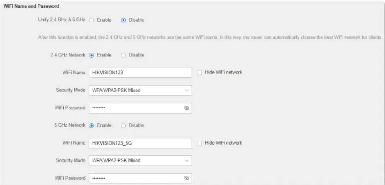
Figure 4-28 Customize the WiFi name and password
Step 6 Click OK.
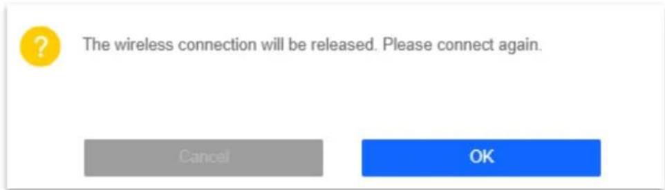
Figure 4-29 Click OK
When the configurations are completed, you can connect to the WiFi networks of the router to access the internet.
Change the WiFi name and WiFi password
The router supports both 2.4 GHz and 5 GHz WiFi networks.
Assume that you want to change the 2.4 GHz WiFi name and password to John_Doe_2.4GHz and Hikvision+Wireless24, and the 5 GHz WiFi name and password to John_Doe_5GHz and Hikvision+Wireless5. Both networks adopt WPA/WPA2-PSK Mixed as the encryption type.
Procedures:
Step 1 Launch a web browser on a device connected to the router and visit http://hikvisionwifi.local to log in to the web UI of the router.
Step 2 Navigate to Route Settings > Wireless Settings > WiFi Name and Password.
Step 3 Set Unify 2.4 GHz & 5 GHz to Disable.
Step 4 Change the parameters of the 2.4 GHz network.
1) Change the WiFi Name of the 2.4 GHz network, which is John_Doe_2.4GHz in this example.
2) Select an Encryption Mode, which is WPA/WPA2-PSK Mixed in this example.
3) Change the WiFi Password of the 2.4 GHz network, which is Hikvision+Wireless24 in this example.
Step 5 Change the parameters of the 5 GHz network.
1) Change the WiFi Name of the 5 GHz network, which is John_Doe_5GHz in this example.
2) Select an Encryption Mode, which is WPA/WPA2-PSK Mixed in this example.
3) Change the WiFi Password of the 5 GHz network, which is Hikvision+Wireless5 in this example.
Step 6 Click Save at the bottom of the page.
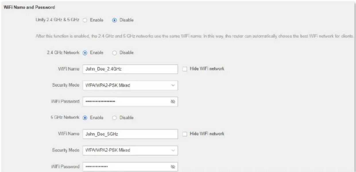
Figure 4-30 Change WiFi name and password
When completing the configurations, you can connect your wireless devices to the WiFi networks of the router to access the internet.
Hide the WiFi network
Procedures:
Step 1 Launch a web browser on a device connected to the router and visit http://hikvisionwifi.local to log in to the web UI of the router.
Step 2 Navigate to Route Settings > Wireless Settings > WiFi Name and Password.
Step 3 Tick Hide WiFi of the target network.
Step 4 Click Save at the bottom of the page.
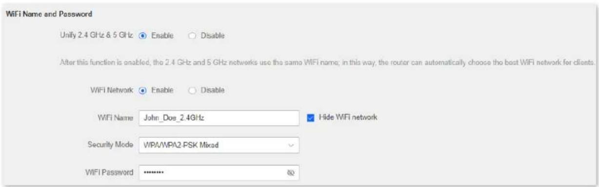
Figure 4-31 Hide WiFi
When the configurations are completed, the corresponding WiFi network is invisible to wireless devices.
Connect to a hidden WiFi network
When a WiFi network is hidden, you need to enter the WiFi name manually to connect to it.
Assume that the Unify 2.4 GHz & 5 GHz function is enabled and the WiFi parameters are:
- WiFi name: Jone_Doe
- Encryption type: WPA/WPA2-PSK Mixed
- WiFi password: Hikvision+Wireless245
i Note
If you do not remember the wireless parameters of the WiFi network, log in to the web UI of the router and navigate to Route Settings > Wireless Settings > WiFi Name and Password to find them.
Procedures (Example: iPhone):
Step 1 Tap Settings on your phone, and find WLAN.
Step 2 Enable WLAN.
Step 3 Scroll the WiFi list to the bottom, and tap Other....
Step 4 Enter the WiFi name and password, which are John_Doe and Hikvision+Wireless245 in this example.
Step 5 Set security to WPA2/WPA3 (If WPA2/WPA3 is not available, choose WPA2).
Step 6 Tap Join.
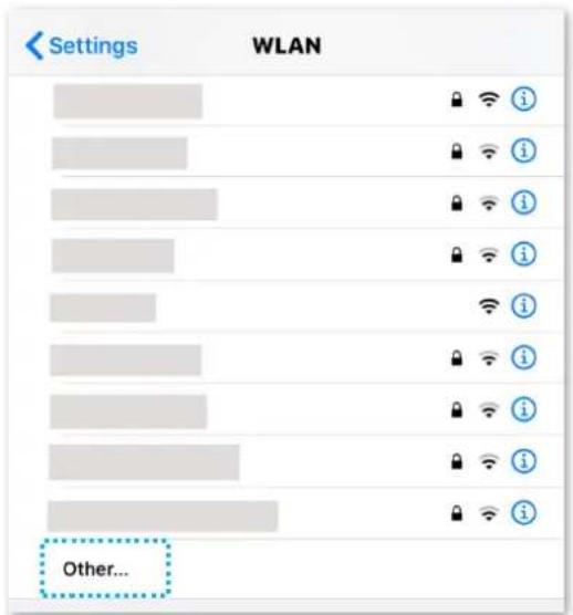
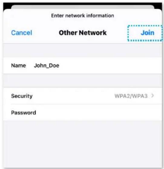
Figure 4-32 Connect to a hidden WiFi network
When the configurations are completed, you can connect to the hidden WiFi network to access the internet.
4.2.2 Guest network
Overview
In this module, you can enable/disable the guest network function and change the WiFi name and password of the guest network.
A guest network can be set up with a shared bandwidth limit for visitors to access the internet and be isolated from the main network. It protects the security of the main network and ensures the bandwidth of your main network.
To access the configuration page, log in to the web UI of the router and navigate to Route Settings > Wireless Settings > Guest Network. This function is disabled by default.
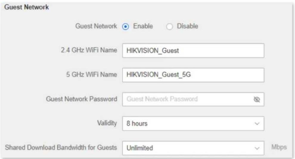
Figure 4-33 Guest network
Table 4-5 Guest network parameter description
| Parameter | Description |
| Guest Network | It is used to enable the Guest Network function. |
| 2.4 GHz WiFi Name | It specifies the WiFi name of the router's guest network. By default, HIKVISION_Guest is for 2.4 GHz WiFi network and HIKVISION_Guest _5G for 5 GHz WiFi network. NoteYou can change the SSIDs (WiFi name) if required. To distinguish the guest network from the main network, you are recommended to set the different WiFi network names. NoteYou can change the SSIDs (WiFi name) if required. To distinguish the guest network from the main network, you are recommended to set the different WiFi network names. |
| 5 GHz WiFi Name | |
| Guest Network Password | It specifies the password for the router's two guest networks. |
| Validity | It specifies the validity of the guest networks.The Guest Network function will be disabled automatically out of the specified time. |
| Shared Download Bandwidth for Guests | It allows you to specify the maximum download speed for all devices connected to the guest networks. By default, the bandwidth is not limited. |
Set up the guest network
Scenario: A group of friends is going to visit your home and stay for about 8 hours.
Goal: Prevent the use of WiFi networks by guests from affecting the network speed of your computer for work purposes.
Solution: You can configure the guest network function and let your guests use the guest networks.
Assume that the parameters you are going to set for the guest WiFi network:
- WiFi names for 2.4 GHz and 5 GHz networks: John_Doe and John_Doe_5G.
- WiFi password for 2.4 GHz and 5 GHz networks: Hikvision+245.
- The shared bandwidth for guests: 2 Mbps.
Procedures:
Step 1 Launch a web browser on a device connected to the router and visit http://hikvisionwifi.local to log in to the web UI of the router.
Step 2 Navigate to Route Settings > Wireless Settings > Guest Network.
Step 3 Set Guest Network to Enable.
Step 4 Change 2.4 GHz WiFi Name, which is John_Doe in this example.
Step 5 Change 5 GHz WiFi Name, which is John_Doe_5G in this example.
Step 6 Set Guest Network Password, which is Hikvision+245 in this example.
Step 7 Select a validity time from the Validity drop-down box, which is 4 hours in this example.
Step 8 Set the bandwidth in the Shared Download Bandwidth for Guests drop-down box, which is 2 in this example.
Step 9 Click Save at the bottom of the page.
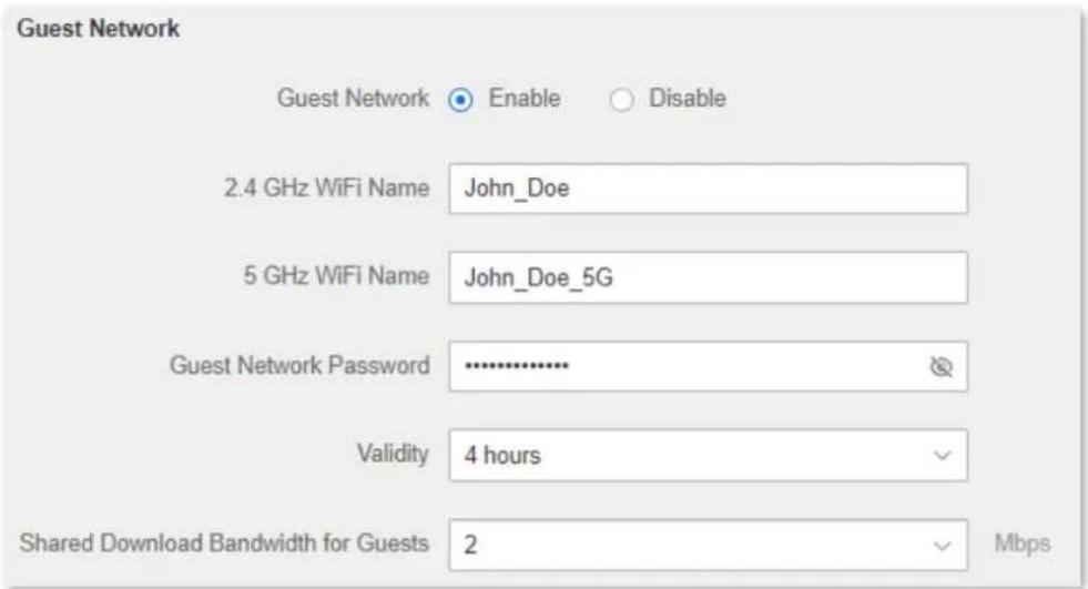
Figure 4-34 Set up the guest network
During the 4 hours after the configuration, guests can connect their wireless devices, such as smartphones, to John_Doe or John_Doe_5G to access the internet and enjoy the shared bandwidth of 2 Mbps.
4.2.3 WiFi signal strength
In this module, you can adjust the wall-penetration capability and wireless coverage of the router.
To access the configuration page, log in to the web UI of the router and navigate to Route Settings > Wireless Settings > Signal Strength Adjustment.
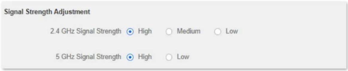
Figure 4-35 Signal strength adjustment
Table 4-6 Signal strength adjustment parameter description
| Parameter | Description |
| Signal Strength Adjustment | The mode of signal strength. The default mode isHigh.High: It is typically used to meet wireless coverage requirements in large or multi-barrier environments.Medium: It is typically used to meet wireless coverage requirements in medium-area or less-obstacle environments.Low: It is typically used to meet wireless coverage requirements in small areas or barrier-free environments. NoteIf the WiFi function works properly in low mode, you are recommended to select the low mode. NoteIf the WiFi function works properly in low mode, you are recommended to select the low mode. |
4.2.4 WiFi parameters
In this section, you can change network mode, wireless channel, and wireless bandwidth of 2.4 GHz and 5 GHz WiFi networks.
To access the configuration page, log in to the web UI of the router, and navigate to Route Settings > Wireless Settings > WiFi Parameters.
i Note
In order not to influence the wireless performance, it is recommended to maintain the default settings on this page without professional instructions.
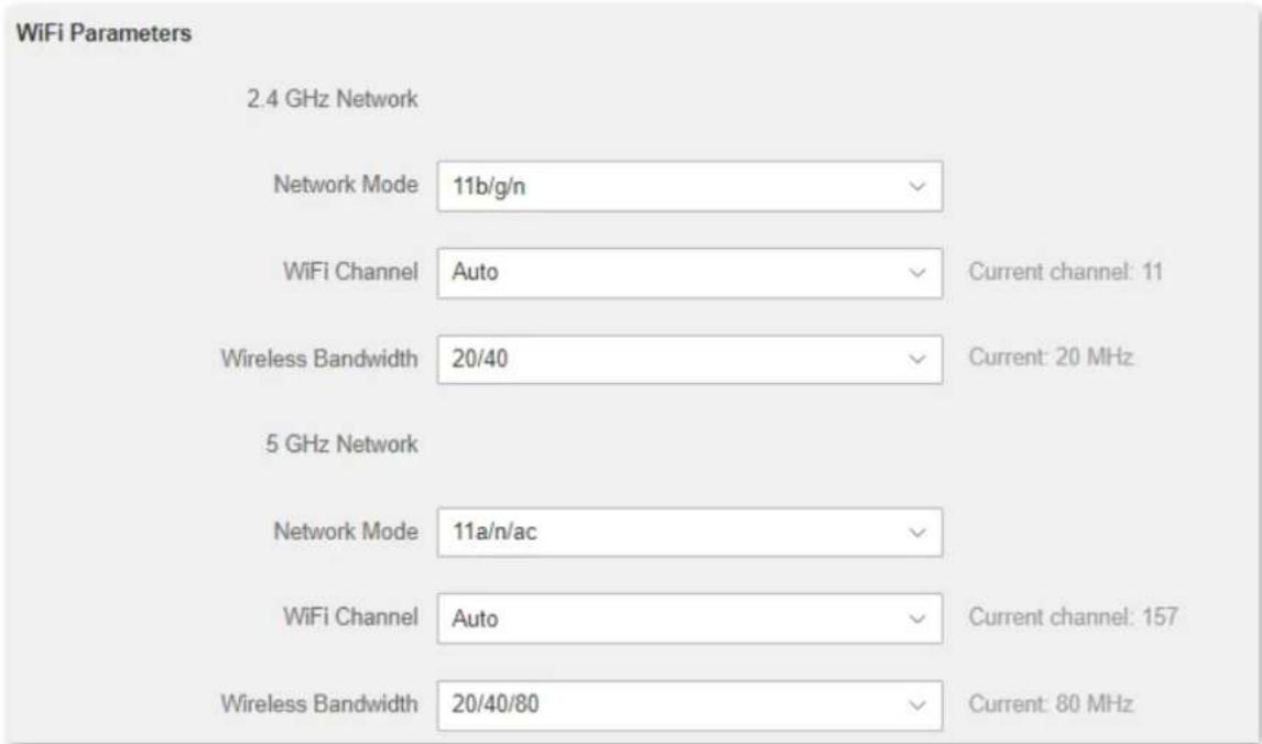
Figure 4-36 WiFi parameters
Table 4-7 WiFi parameter description
| Parameter | Description |
| Network Mode | It specifies various protocols adopted for wireless transmission.2.4 GHz WiFi network supports 11b, 11g, 11b/g mixed and 11b/g/r mixed modes.11b/g/n: It indicates that all devices compliant with IEEE 802.11b or IEEE 802.11g protocol, or work at 2.4 GHz with IEEE 802.11n protocol can connect to the 5 GHz WiFi network of the router, therefore enjoying a maximum transmission rate of 300 Mbps.11b/g: It indicates that devices compliant with IEEE 802.11b or IEEE 802.11g protocol can connect to the 2.4 GHz WiFi network of the router, enjoying a maximum transmission rate of 54 Mbps.11b: It indicates that devices compliant with IEEE 802.11b protocol can connect to the 2.4 GHz WiFi network of the router, enjoying a maximum transmission rate of 11 Mbps.11g: It indicates that devices compliant with IEEE 802.11g protocol can connect to the 2.4 GHz WiFi network of the router, enjoying a maximum transmission rate of 54 Mbps.5 GHz WiFi network supports 11ac, 11a/n/ac mixed modes.11a/n/ac: It indicates that all devices compliant with IEEE 802.11a or IEEE 802.11ac protocol, or work at 5 GHz with IEEE 802.11n protocol can connect to the 5 GHz WiFi network of the router, enjoying a maximum transmission rate of 867 Mbps.11ac: It indicates that devices compliant with IEEE 802.11ac protocol can connect to the 5 GHz WiFi network of the router, enjoying a maximum transmission rate of 867 Mbps. |
| WiFi Channel | It specifies the operating channel of a WiFi network.By default, the wireless channel isAuto, which indicates that the router selects a channel for the WiFi network automatically. You are recommended to choose a channel with less interference for better wireless transmission efficiency. You can use a third-party tool to scan the WiFi signals nearby to understand the channel usage situations. |
| Wireless Bandwidth | It specifies the bandwidth of the wireless channel of a WiFi network. Change the default settings only when necessary.20: It indicates that the channel bandwidth of a router is to 20 MHz.40: It indicates that the channel bandwidth of a router is 40 MHz.80: It indicates that the channel bandwidth of a router is 80 MHz. This option is available only at 5 GHz.20/40/80: It specifies that a router can switch its channel bandwidth between 20 MHz, 40 MHz, and 80 MHz based on the ambient environment. This option is available only at 5 GHz. |
4.2.5 Beamforming
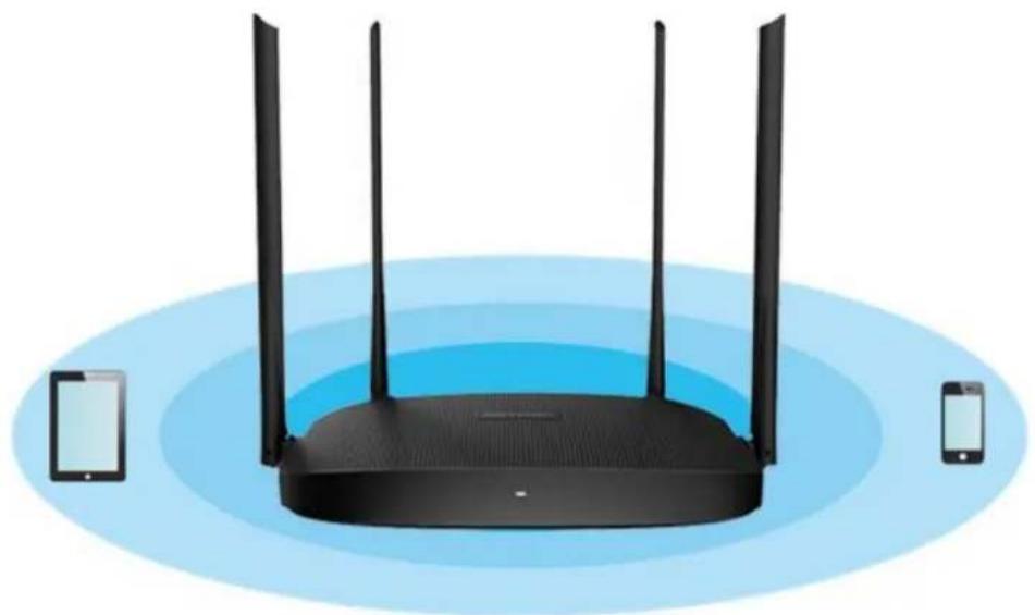
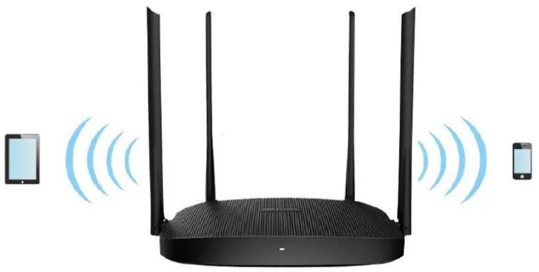
Beamforming is a radio wave technology written into the IEEE 802.11ac standard. With beamforming, the router transmits radio signals in the direction of the client, thus creating stronger, faster, and more reliable wireless communication.
To access the page, log in to the web UI of the router and navigate to Route Settings > Wireless Settings > Beamforming.
The following figure shows the wireless transmission when Beamforming is disabled.
natural_image
Illustration of a wireless router with three antennas and two mobile devices, no text or symbols present.Figure 4-37 Application scenario
The following figure shows the wireless transmission when Beamforming is enabled.
natural_image
Black wireless router with three antennas and two connected devices (no text or symbols visible)Figure 4-38 Application scenario
4.2.6 WPS
The WPS function enables wireless devices such as smartphones to connect to WiFi networks of the router quickly and easily.
To access the page, log in to the web UI of the router and navigate to Route Settings > Wireless Settings > WPS.
i Note
This function is only applicable to WPS-enabled wireless devices.
Connect to the WiFi network using the WPS button
Step 1 Press the WPS button on the router.
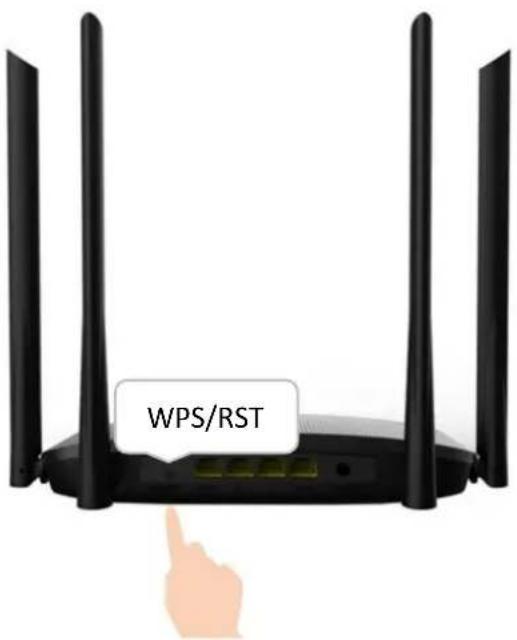
Figure 4-39 Press the WPS button
Step 2 Configure the WPS function on your wireless devices within 2 minutes. Configurations on various devices may differ (Example: HUAWEI P10).
1) Find Settings on the phone.
2) Select WLAN.
3) Tap, and select WLAN settings.
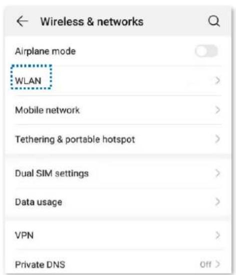
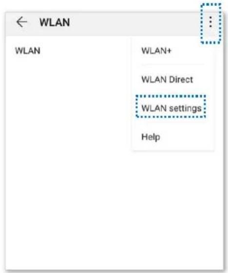
Figure 4-40 Configure the WPS function
4) Select WPS connection.
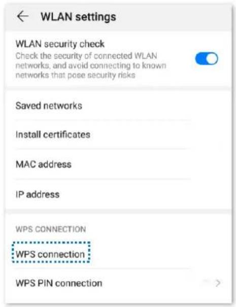
Figure 4-41 Select WPS connection
Wait a moment until the WPS negotiation is completed, and the phone is connected to the WiFi network.
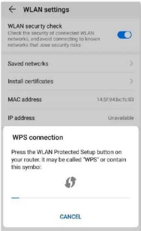
Figure 4-42 WPS negotiation completed
Connect to the WiFi network using the PBC button
Procedures:
Step 1 Launch a web browser on a device connected to the router and visit http://hikvisionwifi.local to log in to the web UI of the router.
Step 2 Navigate to Route Settings > Wireless Settings > WPS.
Step 3 Click PBC.
Step 4 Configure the WPS function on your wireless devices within 2 minutes. Configurations on various devices may differ (Example: HUAWEI P10).
1) Find WLAN settings on the phone.
2) Tap ; and choose WLAN settings.
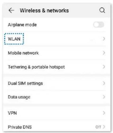
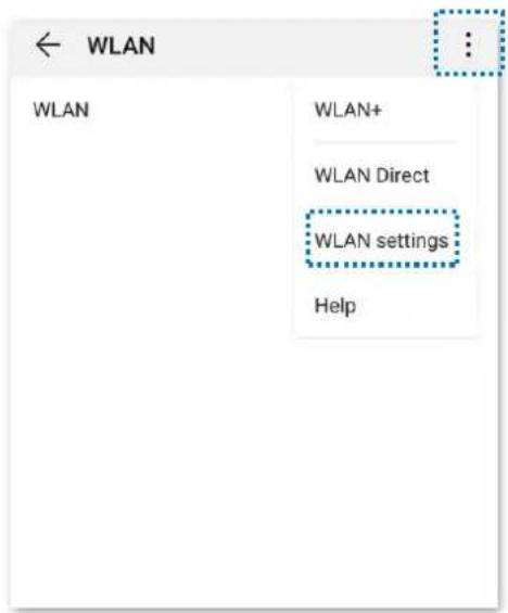
Figure 4-43 Configure the WPS function
3) Select WPS connection.
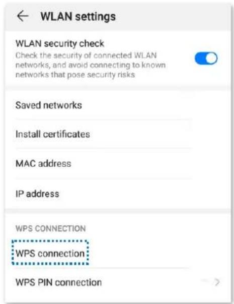
Figure 4-44 Select WPS connection
Wait a moment until the WPS negotiation is completed, and the phone is connected to the WiFi network.
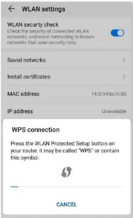
Figure 4-45 WPS negotiation completed
Wait until the smartphone or computer is connected to the WiFi network of the router successfully.
Connect to the WiFi network using the PIN code

Caution
WPS connection using pin code is generally applied on a computer with a wireless adapter. Please refer to the relevant adapter's user guide for detailed instructions.
Step 1 Find the PIN code.
Launch a web browser on the device connected to the router, and visit
http://hikvisionwifi.local. Navigate to Route Settings > Wireless Settings > WPS to check the PIN code.
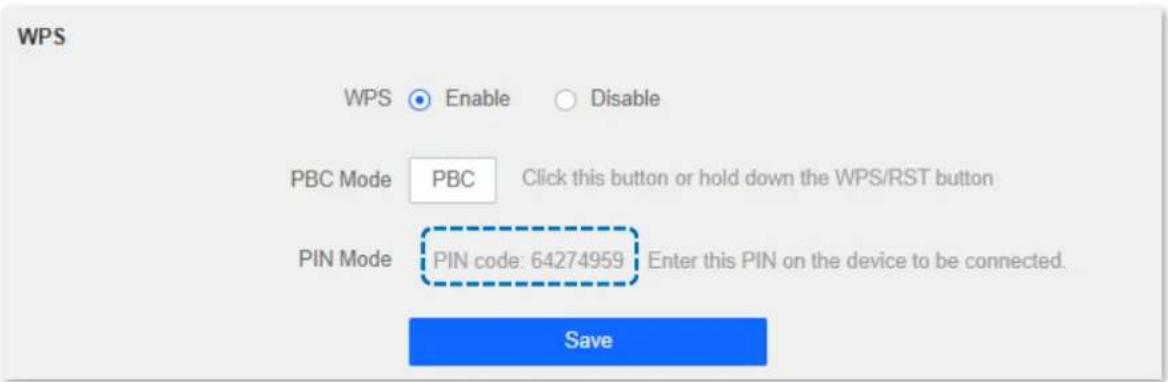
Figure 4-46 Check PIN code
Step 2 Enter the PIN-code on the wireless device for connection.
Wait until the smartphone or computer is connected to the WiFi network of the router successfully.
4.3 IPv6 configuration
This router supports IPv4 and IPv6 dual-stack protocols. In the IPv6 part, you can:
- Connect to the IPv6 network of ISPs
- Change IPv6 LAN settings
- View IPv6 connection status
4.3.1 Connect to the IPv6 network of ISPs
The router can access the IPv6 network of ISPs through three connection types. Choose the connection type by referring to the following chart.
Table 4-8 IPv6 connection type
| Scenario | Connection Type |
| IPv6 service is included in the PPPoE user name and password. | PPPoEv6 |
| The ISP does not provide any PPPoEv6 user name and password.The ISP does not provide information about the IPv6 address.You have a router that can access the IPv6 network. | DHCPv6 |
| The ISP provides you with such information as IPv6 address, subnet mask, default gateway and DNS server. | Static IPv6 |
i Note
Before configuring the IPv6 function, please ensure that you are within the coverage of the IPv6 network and already subscribe to the IPv6 internet service. Contact your ISP for any doubt about it.
PPPoEv6
Overview
If your ISP provides you with the PPPoE user name and password with IPv6 service, you can choose PPPoEv6 to access the internet.
Log in to the web UI of the router, and navigate to Route Settings > IPv6 Configuration > IPv6 WAN Settings. When the connection type is set to PPPoEv6, the page is shown as below.
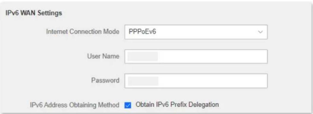
Figure 4-47 IPv6 WAN settings
Table 4-9 IPv6 WAN settings parameter description
| Parameter | Description |
| User Name | It specifies the PPPoE user name and password provided by your ISP. NoteIPv4 and IPv6 services share the same PPPoE account. NoteIPv4 and IPv6 services share the same PPPoE account. |
| Password | |
| IPv6 Address Obtaining Method | When the option is selected, the LAN port of the router obtains the IPv6 prefix from its upstream device.It is recommended to keep the default setting (Selected). If the LAN port cannot obtain the PD prefix, it is because the upstream device does not support PD prefix delivery. Contact your ISP to solve this problem. |
Access the internet through PPPoEv6
The application scenario is shown as below.
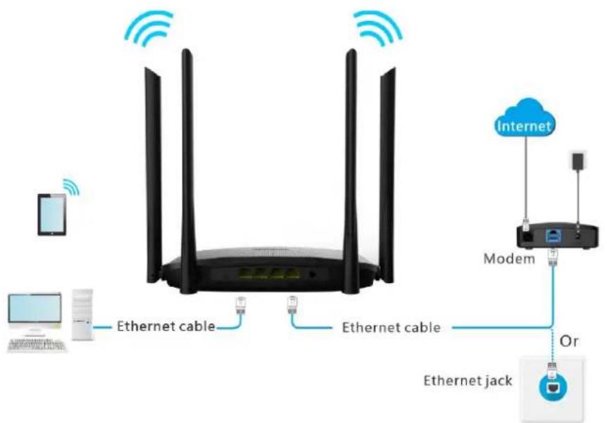
Figure 4-48 Application scenario
Procedures:
Step 1 Launch a web browser on a device connected to the router and visit http://hikvisionwifi.local to log in to the web UI of the router.
Step 2 Navigate to Route Settings > IPv6 Configuration.
Step 3 Set Internet Connection Mode to

Step 4 Set Internet Connection Mode to PPPoEv6.
Step 5 Enter the User Name and Password.
Step 6 Tick Obtain IPv6 Prefix Delegation.
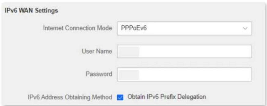
Figure 4-49 Set connection mode to PPPoEv6
Step 7 Click Save at the bottom of the page.
IPv6 network test:
Launch a web browser on a phone or a computer that is connected to the router, and visit test-ipv6.com. The website will test your IPv6 connection status.
When "You have IPv6" is shown on the page, it indicates that the configurations succeed and you can access IPv6 services.
![Test IPv6 connectivity. Summary Tests Run Share Results / Contact Other IPv6 Sites Your IPv4 address on the public Internet appears to be 113.104.250.31 (CHINANET-BACKBONE No.31, Jin-rong Street) Your IPv8 address on the public Internet appears to be 240e:fa:65e:d00:91e2:c8c2:e4fc:cc40 (CHINANET-GUANGDONG-SHENZHEN-MAN CHINANET Guangdong province Shenzhen MAN network) Since you have IPv6, we are including a tab that shows how well you can reach other IPv6 sites. [more info] Your browser has real working IPv6 address - but is avoiding using it. We're concerned about this. [more info] It appears that you use a tunnel mechanism for either IPv4 or IPv6. If you are using a VPN, your VPN is only protecting one protocol, not both. HTTPS support is now available on this site. [more info] Your DNS server (possibly run by your ISP) appears to have IPv6 Internet access. Your readiness score for your IPv6 stability and readiness, when publishers are forced to go IPv6 only 10/10 Click to see Test Data Updated server side IPv6 readiness status)](/content/2026/05/937008/images/7e68cc437b412f7da8c6bd682ac759d39241f382da4816ab99b97dedb117253d.jpg)
Figure 4-50 Test your IPv6 connectivity
If the IPv6 network test fails, try the following solutions:
- Navigate to the Route Settings > IPv6 Configuration > IPv6 Status, ensure that the IPv6 WAN address is a global unicast address.
- Ensure that devices connected to the router obtain their IPv6 address through DHCPv6.
- Consult your ISP.
DHCPv6
DHCPv6 enables the router to obtain IPv6 address from the DHCPv6 server to access the internet, which is applicable in the following scenarios:
- The ISP does not provide any PPPoEv6 user name and password.
- The ISP does not provide information about the IPv6 address.
- You have a router that can access the IPv6 network.
The application scenario is shown as below.
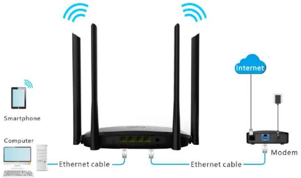
Figure 4-51 Application scenario
Procedures:
Step 1 Launch a web browser on a device connected to the router and visit http://hikvisionwifi.local to log in to the web UI of the router.
Step 2 Navigate to Route Settings > IPv6 Configuration.
Step 3 Set Internet Connection Mode to

Step 4 Set Internet Connection Mode to DHCPv6.
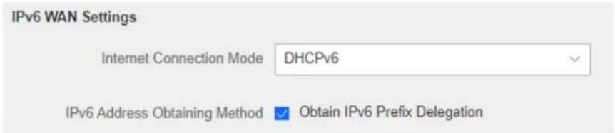
Figure 4-52 Set connection mode to DHCPv6
Step 5 Click Save at the bottom of the page.
Table 4-10 DHCPv6 parameter description
| Parameter | Description |
| IPv6 Address Obtaining Method | When the option is selected, the LAN port of the router obtains the IPv6 prefix from its upstream device.It is recommended to keep the default setting (Selected). If the LAN port cannot obtain the PD prefix, it is because the upstream device does not support PD prefix delivery. Contact your ISP to solve this problem. |
IPv6 network test:
Launch a web browser on a phone or a computer that is connected to the router, and visit test-ipv6.com. The website will test your IPv6 connection status.
When "You have IPv6" is shown on the page, it indicates that the configuration succeeds and you can access IPv6 services.
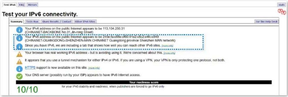
Figure 4-53 Test your IPv6 connectivity
If the IPv6 network test fails, try the following solutions:
- Navigate to Route Settings > IPv6 Configuration > IPv6 Status, ensure that the IPv6 WAN address is a global unicast address.
- Ensure that devices connected to the router obtain their IPv6 address through DHCPv6.
- Consult your ISP.
Static IPv6
Overview
When your ISP provides you with information including IPv6 address, subnet mask, default gateway and DNS server, you can choose this connection type to access the internet with IPv6.
Log in to the web UI of the router, and navigate to Route Settings > IPv6 Configuration > IPv6 WAN Settings. When the connection type is set to Static IPv6 Address, the page is shown as below.
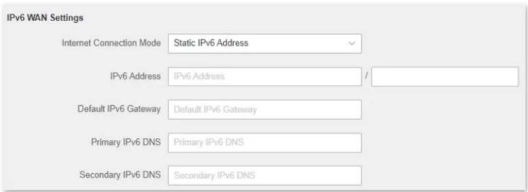
Figure 4-54 Static IPv6 address
Table 4-11 Static IPv6 parameter description
| Parameter | Description |
| IPv6 Address | It specifies the fixed IP address information provided by your ISP. If your ISP only provides one DNS server address, you can leave the Secondary IPv6 DNS blank. If your ISP only provides one DNS server address, you can leave the Secondary IPv6 DNS blank. |
| Default IPv6 Gateway | |
| Primary IPv6 DNS | |
| Secondary IPv6 DNS |
Access the internet through static IPv6
The application scenario is shown as below.
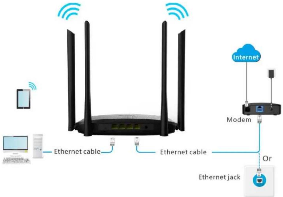
Figure 4-55 Application scenario
Procedures:
Step 1 Launch a web browser on a device connected to the router and visit http://hikvisionwifi.local to log in to the web UI of the router.
Step 2 Navigate to Route Settings > IPv6 Configuration.
Step 3 Set Internet Connection Mode to

Step 4 Set Internet Connection Mode to Static IPv6.
Step 5 Enter the required parameters under IPv6 WAN settings.
Step 6 Enter the IPv6 LAN Address and IPv6 LAN Prefix Length.
Step 7 Click Save at the bottom of the page.
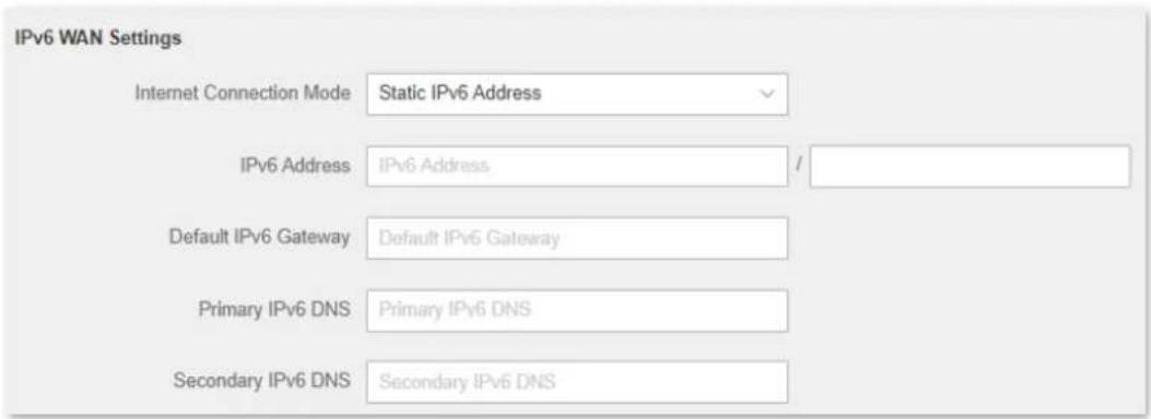
Figure 4-56 Set connection mode to static IPv6
IPv6 network test:
Launch a web browser on a phone or a computer that is connected to the router, and visit test-ipv6.com. The website will test your IPv6 connection status.
When "You have IPv6" is shown on the page, it indicates that the configurations succeed and you can access IPv6 services.
![Test IPv6 FAQ Mirrors Test your IPv6 connectivity. Summary Tests Run Share Results / Contact Other IPv6 Sites For the Help Desk Your IPv4 address on the public Internet appears to be 113.104.250.31 (CHINANET-RACOBONE No.31-Jo:00g St99) Your IPv6 address on the public Internet appears to be 240e:fa:c68e:df00:91e2:c8c2:e4fc:c940 (CHINANET-GUANGDONG-SHENZHEN-MAN CHINANET Guangdong province Shenzhen MAN network) Since you have IPv6, we are including a tab that shows how well you can reach other IPv6 sites. [more info] Your browser has real working IPv6 address - but is avoiding using it. We're concerned about this. [more info] It appears that you use a tunnel mechanism for either IPv4 or IPv6. If you are using a VPN, your VPN is only protecting one protocol, not both. HTTPS support is now available on this site. [more info] Your DNS server (possibly run by your ISP) appears to have IPv6 Internet access. Your readiness score for your IPv6 stability and readiness, when publishers are forced to go IPv6 only 10/10 Click to see Test Data (Updated server side IPv6 readiness stats)](/content/2026/05/937008/images/257244faf448dcf3ead02577d962c3c8fa14132eb67ddcb82222d53a58822635.jpg)
Figure 4-57 Test your IPv6 connectivity
If the IPv6 network test fails, try the following solutions:
- Ensure that you have entered the correct WAN IPv6 address.
- Ensure that devices connected to the router obtain their IPv6 address through DHCPv6.
- Consult your ISP.
4.3.2 IPv6 LAN setup
To access the page, log in to the web UI of the router and navigate to Route Settings > IPv6 Configuration > IPv6 LAN Settings.
You can change the IPv6 LAN settings here.
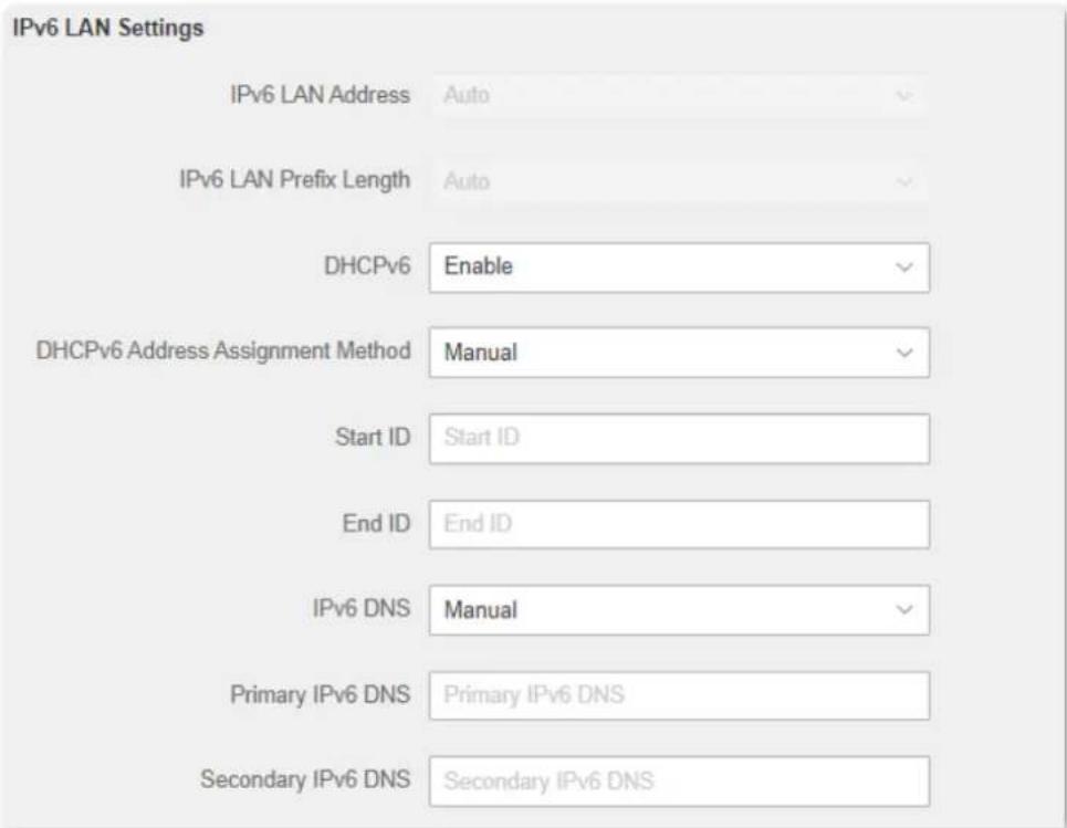
Figure 4-58 IPv6 LAN Settings
Table 4-12 IPv6 LAN parameter description
| Parameter | Description |
| IPv6 LAN Address | It specifies the type of IPv6 LAN address assignment. By default, it isAuto.The router generates the IPv6 address according to its LAN IPv6 address. By default, the prefix has 64 digits. |
| IPv6 LAN Prefix Length | It specifies the type of IPv6 LAN prefix address assignment. By default, it isAuto.The router obtains a LAN prefix from the upstream device. |
| DHCPv6 | DHCPv6 (Dynamic Host Configuration Protocol for IPv6) is used to assign IP addresses and prefixes to IPv6 hosts on a network. It is the IPv6 equivalent of the DHCP for IPv4. This is also known as a stateful autoconfiguration. |
| DHCPv6 Address Assignment Method | It specifies the assignment type of DHCPv6 address for the clients connected to the router.Auto: DHCPv6 stateless configuration. Clients obtain their IPv6 address through Router Advertisement (Stateless Auto Address Configuration) and other parameters are allocated by the DHCPv6 server.Manual: DHCPv6 stateful configuration. The DHCPv6 server automatically assigns IPv6 addresses/prefixes and other network configuration parameters (such as DNS server addresses) to clients. The user needs to manually configure the start ID and the end ID. |
| Start ID | The configuration is required when the IPv6 DHCP type is set to Manual.It specifies the range of the last segment of the IPv6 address that the DHCPv6 server assigns to the devices. Range: 1 to ffff. |
| End ID | |
| IPv6 DNS | It specifies the LAN IPv6 DNS configuration method.Auto: Obtain the IPv6 DNS address from the upstream device.Manual: Configure the IPv6 DNS address manually. |
| Primary IPv6 DNS | It specifies the fixed IPv6 DNS address provided by your ISP here. If your ISP only provides one DNS server address, you can leave the Secondary IPv6 DNS blank. If your ISP only provides one DNS server address, you can leave the Secondary IPv6 DNS blank. |
| Secondary IPv6 DNS |
4.3.3 IPv6 status
To access the page, log in to the web UI of the router and navigate to Route Settings > IPv6 Configuration > IPv6 Status.
You can change the IPv6 information of the router.
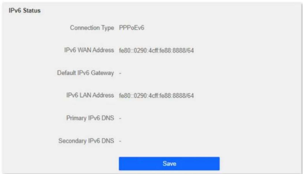
Figure 4-59 IPv6 Status
Table 4-13 IPv6 status parameter description
| Parameter | Description |
| Connection Type | It specifies the IPv6 connection type of the router. |
| IPv6 WAN Address | It specifies the WAN IPv6 address of the router.After the IPv6 function is configured, the WAN port of the router obtains a global unicast IPv6 address or a tunnel address, and a link-local address. |
| Default IPv6 Gateway | It specifies the default IPv6 gateway address of the IPv6 network. |
| IPv6 LAN Address | It specifies the LAN IPv6 address of the router.After the IPv6 function is configured, the LAN port of the router obtains a global unicast IPv6 address or a tunnel address, and a link-local address. |
| Primary IPv6 DNS | It specifies the primary and secondary DNS server addresses of the IPv6 network. |
| Secondary IPv6 DNS |
4.4 Sleeping mode
4.4.1 LED control
This page allows you to turn on and turn off the LED indicator of the router as required.
To access the configuration page, log in to the web UI of the router and navigate to Route Settings > Sleeping Mode > LED Control.

Figure 4-60 LED control

Danger
To make the LED control function work properly, please ensure the system time is synchronized with the internet time.
Table 4-14 LED control parameter description
| Parameter | Description |
| Always On | It indicates that the LED indicator works in ordinary states. |
| Always Off | It indicates that the LED indicator is off even when the router is working. |
| Scheduled | It specifies that the LED indicator is turned off as scheduled. |
4.4.2 WiFi schedule
When the WiFi schedule function is enabled, the router disables the WiFi network during the specified period to reduce power consumption.
To access the configuration page, log in to the web UI of the router, and navigate to Route Settings > Sleeping Mode > WiFi Schedule.
This function is disabled by default. When it is enabled, the page is shown as below.
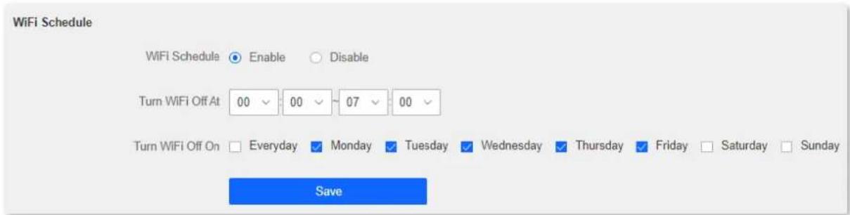
Figure 4-61 WiFi schedule

Caution
To make the WiFi schedule function work properly, please ensure the system time is synchronized with the internet time.
Table 4-15 WiFi schedule parameter description
| Parameter | Description |
| WiFi Schedule | It is used to enable/disable the WiFi Schedule function. |
| Turn WiFi Off At | It specifies the period when the WiFi network is disabled. During that period, wireless devices cannot find the router's WiFi networks. |
| Turn WiFi Off On | It specifies the day(s) when the WiFi network is disabled. |
Chapter 5 Client management
5.1 Access control
5.1.1 Overview
By configuring this function, you can limit the upload and download speed of devices connected to the router and allocate the bandwidth reasonably. On this page you can:
- Set the upload and download speed limit
- Add devices to the blacklist
- Remove devices from the blacklist
To access the configuration page, log in to the web UI of the router and navigate to Client Management > Access Control.
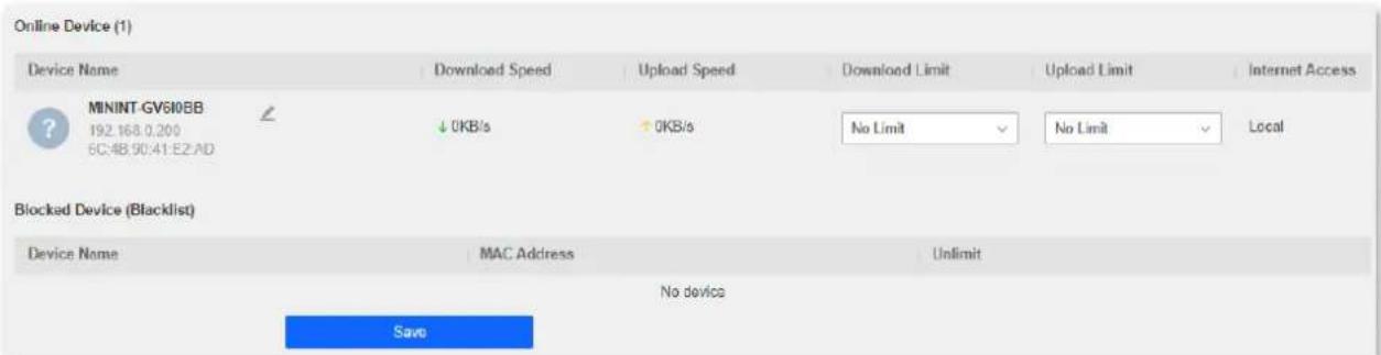
Figure 5-1 Access control
Table 5-1 Access control parameter description
| Parameter | Description | |
| Online Devices | Device Name | It shows the information of the online device, including the device name and IP address.You can click to customize the device name for easier management. |
| Download Speed | It specifies the current upload and download speeds of the device. | |
| Upload Speed | ||
| Download Limit | It allows you to specify the maximum upload and download speeds for the device. | |
| Upload Limit | ||
| Internet Access | It specifies whether the device can access the internet.●: It indicates that the device can access the internet.●: It indicates that the device is unable to access the internet.●Local: It indicates that the device is managing the web UI of the router. | |
| Blacklisted Devices | Device Name | It specifies the device name of a blocked device. |
| MAC Address | It specifies the MAC address of a blocked device. | |
| Unlimit | It is used to remove a blocked device from the blacklist. After being removed from the blacklist, the device can reconnect to the router for internet access. | |
5.1.2 Set the upload and download speed limit
Scenario: You want to allocate bandwidth equally and enable all connected devices to enjoy smooth 720p videos.
Solution: Configure the bandwidth control function to meet the requirement.
Procedures:
Step 1 Launch a web browser on a device connected to the router and visit http://hikvisionwifi.local to log in to the web UI of the router.
Step 2 Navigate to Client Management > Access Control.
Step 3 Target the devices to be controlled, set the Download Limit to 512 KB/s (HD Videos), and set the Upload Limit to 32KB/s.
Step 4 Click Save at the bottom of the page.

Figure 5-2 Set the upload and download speed limit
After the configuration, the highest speed for the device is 4 Mbps (or 512 KB/s) and satisfies the requirement of 720p videos.
5.1.3 Add the device to the blacklist
Add devices to the blacklist to block internet access:
Step 1 Launch a web browser on a device connected to the router and visit http://hikvisionwifi.local to log in to the web UI of the router.
Step 2 Navigate to Client Management > Access Control.
Step 3 Click corresponded to the device to be blocked to change the status to .


Figure 5-3 Add device to the blacklist
Step 4 Click Save at the bottom of the page.
The blocked device is shown on the blacklist.

Figure 5-4 Blocked device
5.1.4 Remove the device from the blacklist
Procedures:
Step 1 Launch a web browser on a device connected to the router and visit http://hikvisionwifi.local to log in to the web UI of the router.
Step 2 Navigate to Client Management > Access Control > Blocked Device (Blacklist).
Step 3 Target the device and click to .
Step 4 Click Save at the bottom of the page.

Figure 5-5 Blocked device
After the device is removed from the blacklist, it can access the internet through the router again.
5.2 Parental control
5.2.1 Overview
On the parental control page, you can view the information of online devices and configure their internet access options.
To access the configuration page, log in to the web UI of the router, and navigate to Client Management > Parental Control page.
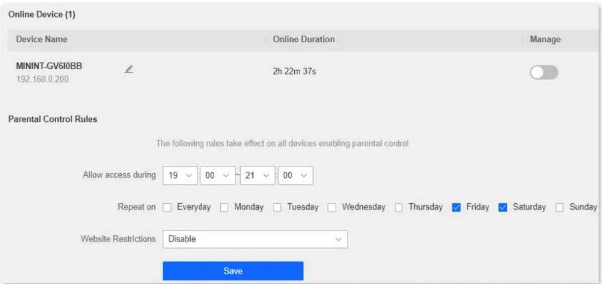
Figure 5-6 Parental control
Table 5-2 Parental control parameter description
| Parameter | Description | |
| Online Devices | Device Name | It specifies the name of the online device.You can click ↙ to customize the device name for easier management. |
| IP Address | It specifies the IP address of the online device. | |
| Online Duration | It specifies the time that has elapsed since the device connects to the router successfully. | |
| Manage | It specifies the status of a rule. You can enable/disable the rule by switching the button. | |
| Access Restrictions | Allow access during | It specifies the period when the internet connection is allowed. |
| Repeat | It specifies the dates when the internet connection is allowed. | |
| Website Restrictions | It specifies the modes of website restrictions.● Disable: It specifies that all websites are accessible.● Only Permit: It specifies that only the websites listed in Unblocked Websites are accessible.● Only Forbid: It specifies that only the websites listed in Blocked Websites are inaccessible. | |
| Unblocked Websites | It specifies the websites that devices can or cannot access during the "Allow access during" period. NoteKey words are supported for access restriction. Full website addresses are recommended for precise limits. NoteKey words are supported for access restriction. Full website addresses are recommended for precise limits. | |
| Blocked Websites | ||
Note
5.2.2 An example of configuring parental control
Scenario: The final exam for your daughter is approaching and you want to configure her internet access through the router.
Goal: Your daughter cannot access websites, such as Facebook, Twitter, Youtube, and Instagram, from 8:00 to 22:00 on weekends using the computer in her room, and cannot access the internet from 22:00 to 8:00.
Solution: You can configure the parental controls function to reach the goal.
Procedures:
Step 1 Launch a web browser on a device connected to the router and visit http://hikvisionwifi.local to log in to the web UI of the router.
Step 2 Navigate to Client Management > Parental Control.
Step 3 Set the button from to .


Figure 5-7 Configure parental control
Step 4 Specify the period when the target websites cannot be accessed, which is 8:00 \~ 22:00 in this example.
Step 5 Tick the days when the rule is applied, which are Saturday and Sunday in this example.
Step 6 Set Website Restrictions to Only Forbid.
Step 7 Set Blocked Websites, which are facebook.com, twitter.com, youtube.com and instagram.com.
Step 8 Click Save at the bottom of the page.
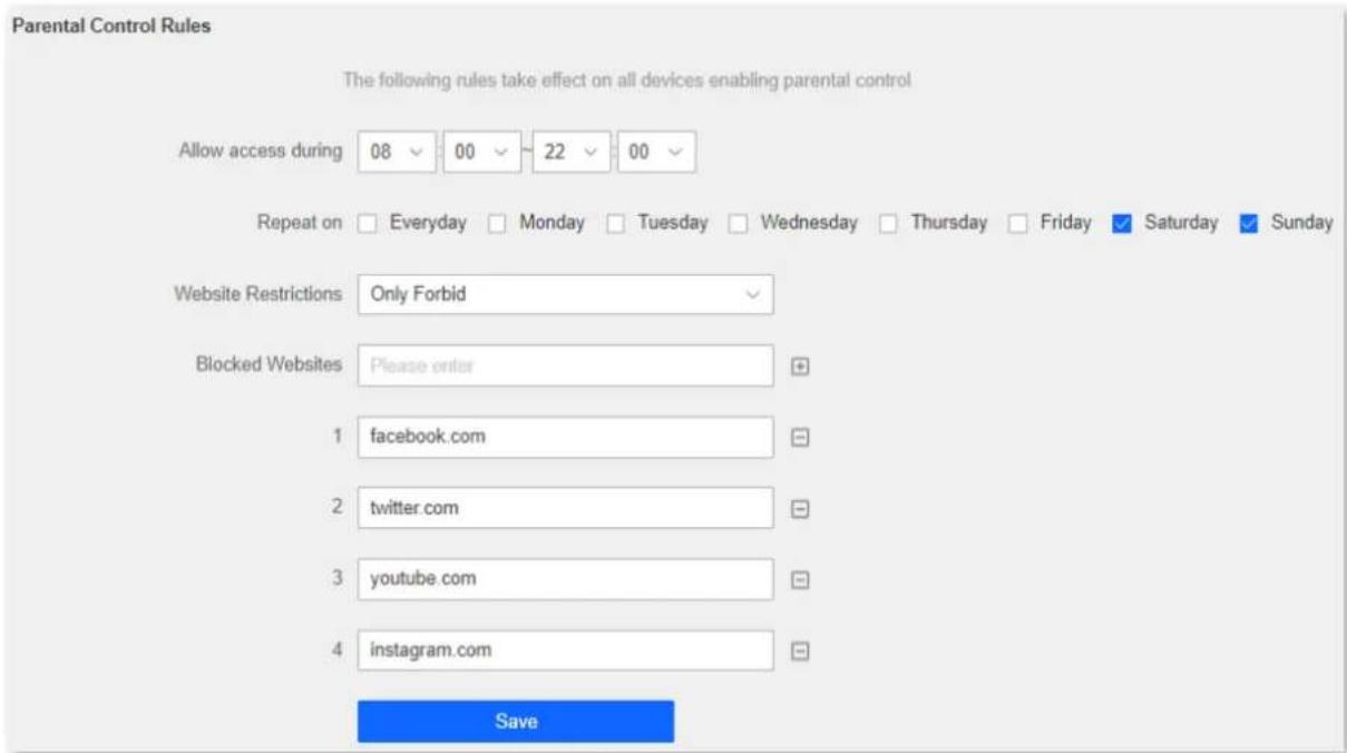
Figure 5-8 Set parental control rules
After the configuration is completed, your daughter can access any websites except for Facebook, Twitter, Youtube, and Instagram from 8:00 to 22:00 on weekends, and she cannot access the internet at all between 22:00 to 8:00.
Chapter 6 Advanced
6.1 MAC address filter
6.1.1 Overview
This function enables you to add devices to the whitelist or blacklist to enable or disable specified users to access the internet through the router.
To access the configuration page, log in to the web UI of the router, and navigate to Advanced > MAC Address Filter.
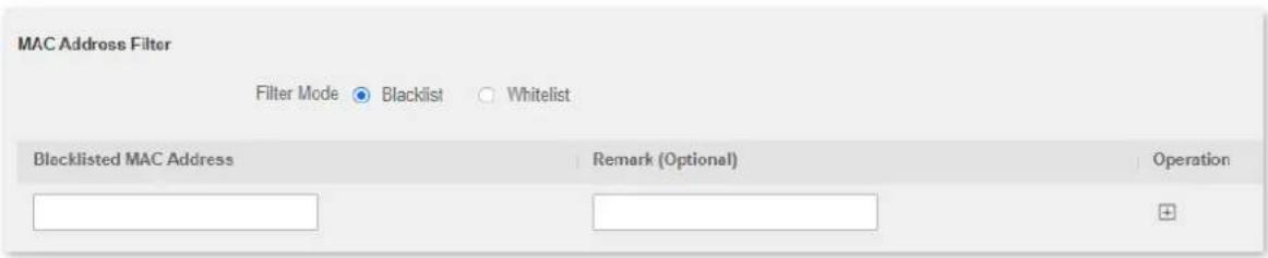
Figure 6-1 MAC address filter
Table 6-1 MAC address filter parameter description
| Parameter | Description |
| Filter Mode | It specifies the MAC address filter mode.●Blacklist: Wireless devices listed are unable to connect to the WiFi network of the router, and wired devices listed are unable to access the internet.●Whitelist: Only wireless devices listed can connect to the WiFi network of the router, and wired devices listed can access the internet. |
| Blacklisted MAC Address | It specifies the MAC address of the device to which a rule applies. |
| Whitelisted MAC Address | |
| Remark (Optional) | It specifies the description of a rule. |
| Operation | +: Click it to add a device to the blacklist/whitelist.+: Click it to delete a device from the blacklist/whitelist. |
| Whitelist all online devices | It is only available when you set the whitelist for the first time. By clicking it, you can add all currently connected devices to the whitelist. |
6.1.2 Only allow specified device to access the internet
Scenario: The WiFi network in your home is misused by unknown users sometimes.
Goal: Only allow certain devices of family members to access the internet.
Solution: You can configure the MAC address filter function to reach the goal.
Assume the MAC address and connection status of your domestic devices are as follows.
Table 6-2 MAC address connection status
| Device | MAC address | Status |
| Your own phone | 6C:4B:90:41:E2:AD | Connected |
| Wife's phone | 94:C6:91:29:C2:12 | Disconnected |
| Daughter's phone | 98:9C:57:19:D0:1B | Disconnected |
Procedures:
Step 1 Launch a web browser on a device connected to the router and visit http://hikvisionwifi.local to log in to the web UI of the router.
Step 2 Navigate to Advanced > MAC Address Filter.
Step 3 Set the Filter Mode to Whitelist.
Step 4 Enter the Whitelisted MAC Address of the device, which is 94:C6:91:29:C2:12 in this example.
Step 5 (Optional) Enter the remark for the device, which is Wife's phone in this example.
Step 6 Click
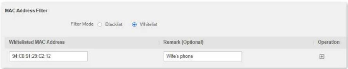
Figure 6-2 Add white MAC address
Step 7 Repeat Step 4 to Step 6 to add the Daughter's phone (98:9C:57:19:D0:1B) to the whitelist.
Step 8 Click Save at the bottom of the page.
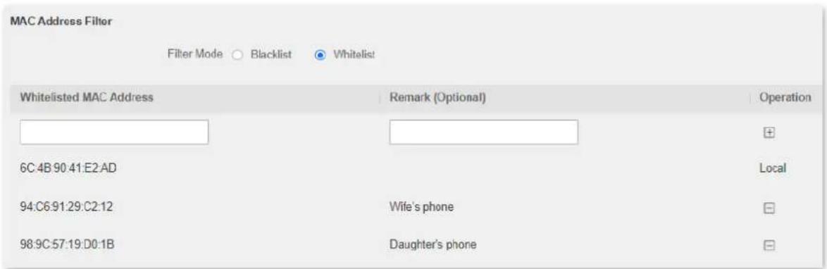
Figure 6-3 Whitelisted MAC address
When the configuration is completed, only the three devices added can access the internet through the router.
6.2 IPTV
6.2.1 Overview
If the IPTV service is included in the broadband service you purchased, you can enable the IPTV function to enjoy both internet access and IPTV programs through the router at the same time.
To access the configuration page, log in to the web UI of the router, and navigate to Advanced > IPTV.
This function is disabled by default. When it is enabled, the page is shown as below.
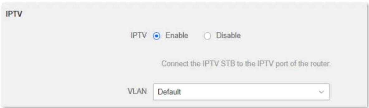
Figure 6-4 IPTV
Table 6-3 IPTV parameter description
| Parameter | Description |
| IPTV | It is used to enable or disable the IPTV function of the router.When this function is enabled, the port IPTV/3 can be used only as an IPTV port to be connected to an IPTV set-top box. |
| VLAN | It specifies the VLAN ID of your IPTV service.If you do not have any information about VLAN provided by your ISP, please keep Default.If you are using the IPTV service in Shanghai, choose Shanghai VLAN and choose the proper VLAN ID.If you have a VLAN ID from your ISP, please choose Manual VLAN and enter the VLAN value. |
6.2.2 Watch IPTV program through the router
Scenario: The IPTV service is included in your broadband service. You have obtained the IPTV account and password from your ISP, but no VLAN information.
Goal: Be able to watch IPTV programs through the router.
Solution: You can configure the IPTV function to reach the goal.
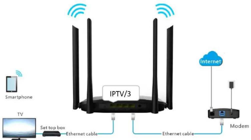
Figure 6-5 Application scenario
Procedures:
Step 1 Set your router.
1) Launch a web browser on a device connected to the router and visit http://hikvisionwifi.local to log in to the web UI of the router.
2) Navigate to Advanced > IPTV.
3) Set IPTV to Enable.
4) Click Save at the bottom of the page.
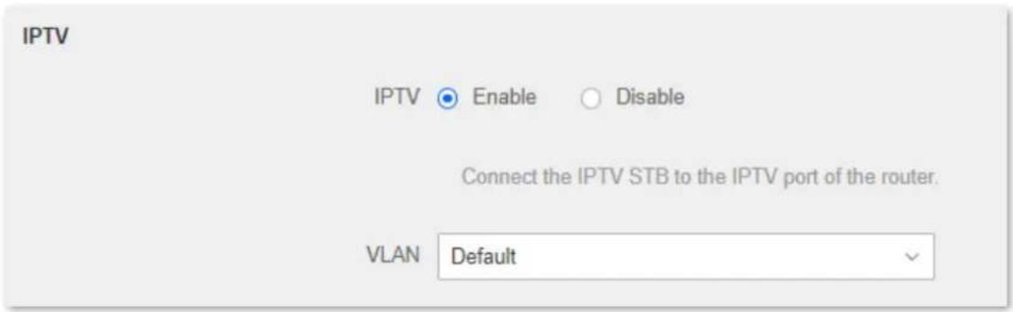
Figure 6-6 Enable the IPTV
5) Click OK.
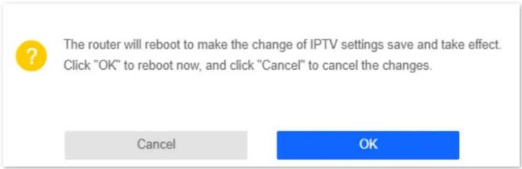
Figure 6-7 Click OK
Step 2 Set the set-top-box.
Dial-up on set-top-box with the account and password provided by ISP. After the configuration is completed, you can watch IPTV programs on the TV.
6.3 IP-MAC binding
6.3.1 Overview
Through the IP-MAC binding function, specified clients can always obtain the same IP address when connecting to the router, ensuring that the router's "Port Mapping", "DDNS", "DMZ host" and other functions can function normally. This function takes effect only when the DHCP server function of the router is enabled.
To access the configuration page, log in to the web UI of the router, and navigate to Advanced > IP-MAC Binding.

Figure 6-8 IP-MAC binding
Table 6-4 IP-MAC binding parameter description
| Parameter | Description |
| IP Address | It specifies the IP address to be reserved for the client with the specified MAC address. It should belong to the DHCP address pool. |
| MAC Address | It specifies the MAC address of the client that needs a fixed IP address. |
| Operation | +: It is used to add an IP-MAC binding rule.+: It is used to delete an IP-MAC binding rule. |
6.3.2 Assign fixed IP addresses to LAN clients
Scenario: You have set up an FTP server within your LAN.
Goal: Assign a fixed IP address to the host of the FTP server and prevent the failure of access to the FTP server owing to the change of IP address.
Solution: You can configure the IP-MAC binding function to reach the goal.
Assume that the information of the FTP server includes:
The fixed IP address for the server: 192.168.0.136
- MAC address of the FTP server host: 00 00 00 00 00 01
Procedures:
Step 1 Launch a web browser on a device connected to the router and visit http://hikvisionwifi.local to log in to the web UI of the router.
Step 2 Navigate to Advanced > IP-MAC Binding.
Step 3 Enter an IP address included in the DHCP address pool, which is 192.168.0.136 in this example.
Step 4 Enter the MAC address of the client which needs a fixed IP address, which is 00:00:00:00:00:01 in this example.
Step 5 Click
Step 6 Click Save at the bottom of the page.

Figure 6-9 IP-MAC binding
When the configuration is completed, the page is shown as below and the FTP server host always gets the same IP address when connecting to the router, which is 192.168.0.136 in this example.

Figure 6-10 IP-MAC binding
6.4 Port mapping
6.4.1 Overview
By default, internet users cannot actively access the LAN of the router.
The port mapping function opens a port of the router, and binds the LAN server to the port using the server's IP address and intranet service port. All-access requests to the WAN port of the router will be directed to the server. Therefore, the server within the LAN can be accessed by internet users and the LAN can be free from attacks from the internet.
For example, the port mapping function enables internet users to access web servers or FTP servers within the LAN.
To access the configuration page, log in to the web UI of the router, and navigate to Advanced > Port Mapping.

Figure 6-11 Port mapping
Table 6-5 Port mapping parameter description
| Parameter | Description |
| Internal IP Address | It specifies the IP address of a server that resides on the LAN. |
| Internal Port | It specifies the service port number of the internal server.You can either choose a port from the drop-down list or specify a port manually. |
| External Port | It specifies the service port number for internet users to access a specified service.When the internal port is selected or specified, the external port will be occupied automatically. You can also change it as required. |
| Protocol | It specifies the protocol that specified service uses.Both indicate that both TCP and UDP are used. If you are uncertain about it,Bothare recommended. |
| Operation | +: It is used to add a port mapping rule.-: It is used to delete a port mapping rule. |
6.4.2 Enable internet users to access LAN resources using an IP address
Scenario: You have set up an FTP server within your LAN.
Goal: Open the FTP server to internet users and enable family members who are not at home to access the resources of the FTP server from the internet.
Solution: You can configure the port mapping function to reach the goal.
Assume that the information of the FTP server includes:
- IP address: 192.168.0.125
- MAC address: 00 00 00 00 00 01
- Service port: 21
- The WAN IP address of the router: X.X.X.X.
i Note
- Please ensure that the router obtains an IP address from the public network. This function may not work on a host with an IP address of a private network or an intranet IP address assigned by ISPs that start with 100. Common IPv4 addresses are classified into class A, class B and class C. Private IP addresses of class A range from 10.0.0.0 to 10.255.255.255; Private IP addresses of class B range from 172.16.0.0 to 172.31.255.255; Private IP addresses of class C range from 192.168.0.0 to 192.168.255.255.
- ISPs may block unreported web services to be accessed with the default port number 80. Therefore, when the default LAN port number is 80, please change it to an uncommon port number (1024 to 65535) manually, such as 9999.
● The LAN port number and the WAN port number can be different.
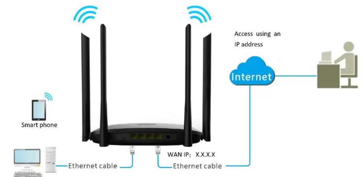
flowchart
graph TD
    A["Smart phone"] -->|Ethernet cable| B["Romega"]
    C["Computer"] -->|Ethernet cable| B
    B -->|Wi-Fi| D["Internet"]
    D -->|Access using an IP address| E["User at desk"]
Figure 6-12 Application scenario
FTP server
- IP:192.168.0.125
- MAC: 00:00:00:00:00:01
— Port number 21
Procedures:
Step 1 Launch a web browser on a device connected to the router and visit http://hikvisionwifi.local to log in to the web UI of the router.
Step 2 Add a port mapping.
1) Navigate to Advanced > Port Mapping.
2) Enter the Internal IP Address, which is 192.168.0.125 in this example.
3) Select an Internal Port in the drop-down box, which is 21 in this example.
4) Select a protocol, which is Both in this example.
5) Click
6) Click Save at the bottom of the page.

Figure 6-13 Add a port mapping
The port mapping rule is added when the page is shown as below.

Figure 6-14 Port mapping rule is added
Step 3 Assign a fixed IP address to the host where the server locates.
1) Navigate to Advanced > IP-MAC Binding.
2) Specifies an IP Address for the host of the server, which is 192.168.0.125 in this example.
3) Enter the MAC Address of the host of the server, which is 00:00:00:00:00:01 in this example.
4) Click .+
5) Click Save at the bottom of the page.

Figure 6-15 IP-MAC binding
When completing the configurations, users from the internet can access the FTP server by visiting "Intranet service application layer protocol name://WAN IP address of the router". If the external port number is not the same as the default intranet service port number, the visiting address should be: "Intranet service application layer protocol name://WAN IP address of the router:external port number".
In this example, the address is "ftp://X.X.X.X". You can find the WAN IP address of the router in View system information.
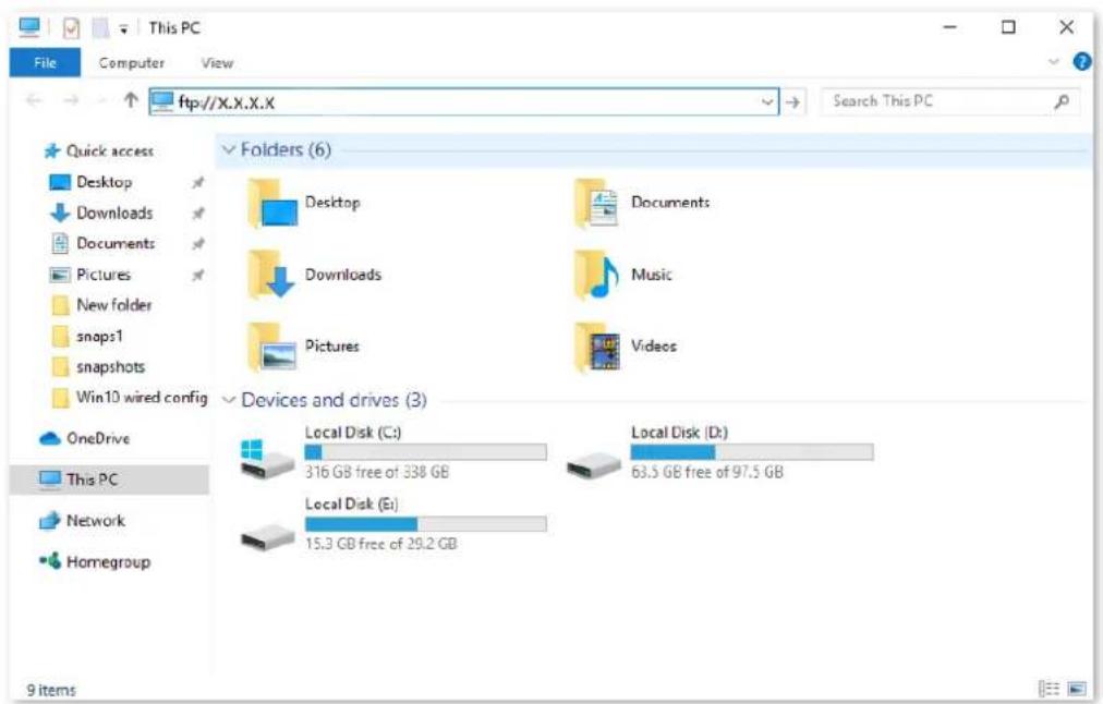
Figure 6-16 Enter the ftp://X.X.X.X
Enter the user name and password to access the resources on the FTP server.
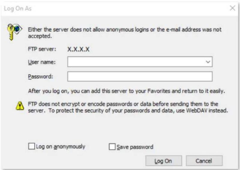
Figure 6-17 Enter the user name and password
If you want to access the server within a LAN using a domain name, refer to the solution DDNS + Port mapping.
i Note
After the configurations, if internet users still cannot access the FTP server, try the following methods:
- Ensure that the internal port number configured in the port mapping function is the same as the service port number set on the server.
- Close the firewall, antivirus software and security guards on the host of the FTP server and try again.
6.5 DDNS
6.5.1 Overview
DDNS normally interworks with port mapping, DMZ host and remote management, so that the internet users can be free from the influence of dynamic WAN IP addresses and access the internal server or the router's web UI with a fixed domain name.
To access the configuration page, log in to the web UI of the router, and navigate to Advanced > DDNS.
This function is disabled by default. When it is enabled, the page is shown as below.
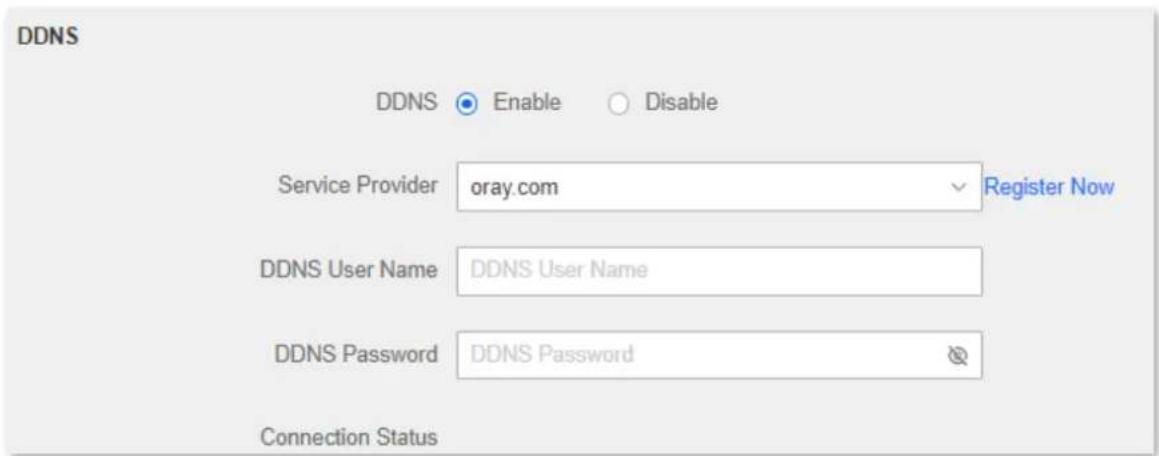
Figure 6-18 DDNS
Table 6-6 DDNS parameter description
| Parameter | Description |
| DDNS | It specifies whether to enable the DDNS function. |
| Service Provider | It specifies a DDNS service provider, including oray.com, 88ip.cn and dyn.com. |
| DDNS User Name | It specifies the user name and password registered on a DDNS service provider's website for logging in to the DDNS service. |
| DDNS Password | |
| DDNS Host Name | It specifies the domain name you applied on the website of your service provider.It is only required when dyn.com is chosen as the service provider. |
| Connection Status | It specifies the current connection status of the DDNS service. |
6.5.2 Enable internet users to access LAN resources using a domain name
Scenario: You have set up an FTP server within your LAN.
Goal: Open the FTP server to internet users and enable family members who are not at home to access the resources of the FTP server from the internet with a domain name.
Solution: You can configure the DDNS and port mapping functions to reach the goal.
Assume that the information of the FTP server includes:
- IP address: 192.168.0.125
- MAC address of the host: 00:00:00:00:00:01
- Service port: 21
The information of the registered DDNS service:
- Service provider: oray.com
- User name: JohnDoe
- Password: JohnDoe123456
- Domain name: XXXX.zicp.vip

Note
Please ensure that the router obtains an IP address from the public network. This function may not work on a host with an IP address of a private network or an intranet IP address assigned by ISPs that start with 100. Common IPv4 addresses are classified into class A, class B and class C. Private IP addresses of class A range from 10.0.0.0 to 10.255.255.255; Private IP addresses of class B range from 172.16.0.0-172.31.255.255; Private IP addresses of class C range from 192.168.0.0-192.168.255.255.
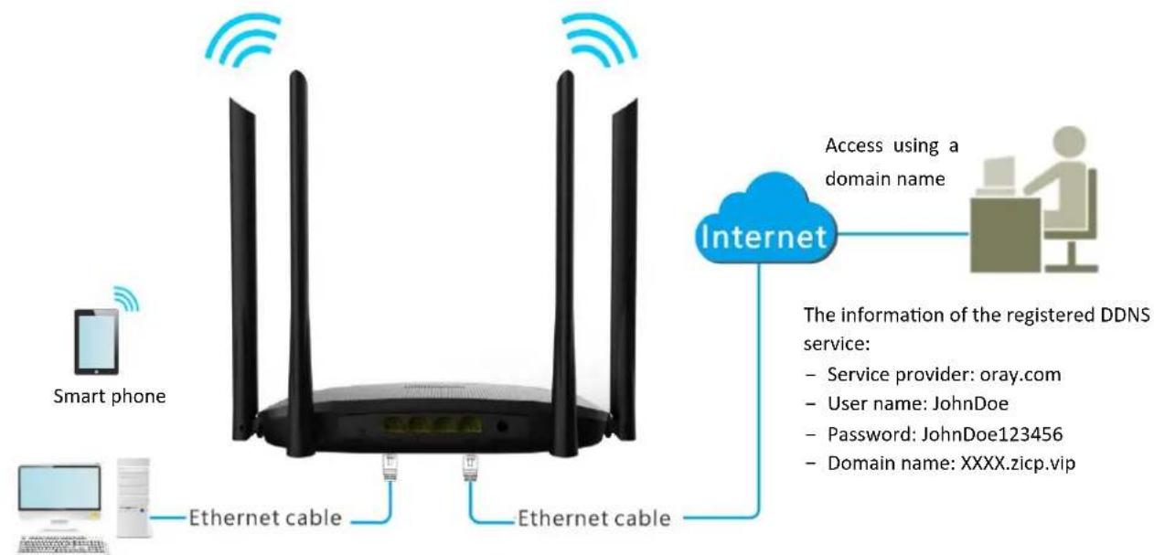
flowchart
graph TD
    A["Smart phone"] -->|Ethernet cable| B["Router"]
    C["Computer"] -->|Ethernet cable| B
    B -->|Ethernet cable| D["Internet"]
    D --> E["Access using a domain name"]
    E --> F["The information of the registered DDNS service:"]
    F --> G["Service provider: oray.com"]
    F --> H["User name: JohnDoe"]
    F --> I["Password: JohnDoe123456"]
    F --> J["Domain name: XXXX.zicp.vip"]
FTP server
— IP: 192.168.0.125
— MAC: 00:00:00:00:00:01
— Port number: 21
Figure 6-19 Application scenario
Procedures:
Step 2 Launch a web browser on a device connected to the router and visit http://hikvisionwifi.local to log in to the web UI of the router.
Step 3 Configure the DDNS function.
1) Navigate to Advanced > DDNS.
2) Set DDNS to Enable.
3) Select a service provider, which is oray.com in this example.
4) Enter the user name and password, which are JohnDoe and JohnDoe123456 in this example.
5) Click Save at the bottom of the page.
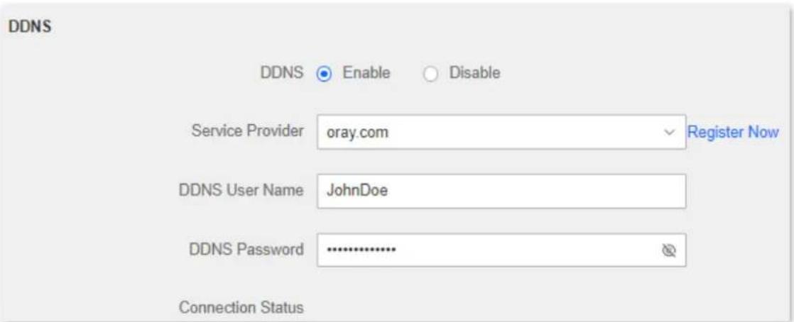
Figure 6-20 Configure DDNS
Wait a moment, when the Connection Status turns Connected, the configurations succeed.
Step 4 Configure the port mapping function (refer to Port mapping).
When completing the configurations, users from the internet can access the FTP server by visiting "Intranet service application layer protocol name://the domain name". If the external port number is not the same as the default intranet service port number, the visiting address should be: "Intranet service application layer protocol name://the domain name:external port number".
In this example, the address is ftp://XXXX.zicp.vip.
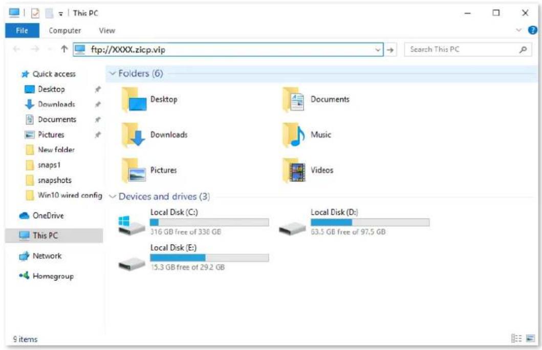
Figure 6-21 Enter the ftp://XXXX.zip.vip
Enter the user name and password to access the resources on the FTP server.
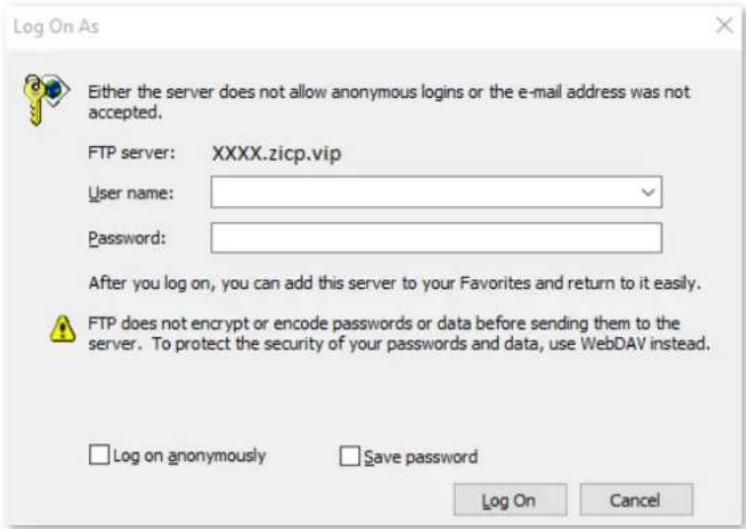
Figure 6-22 Enter the user name and password

Note
After the configurations, if internet users still cannot access the FTP server, try the following methods:
- Ensure that the LAN port number configured in the port mapping function is the same as the service port number set on the server.
- Close the firewall, antivirus software and security guards on the host of the FTP server and try again.
6.6 DMZ host
6.6.1 Overview
A DMZ host on a LAN is free from restrictions when communicating with the internet. It is useful for getting a better and smoother experience in video conferences and online games. You can also set the host of a server within the LAN as a DMZ host when in need of accessing the server from the internet.

Caution
- A DMZ host is not protected by the firewall of the router. A hacker may leverage the DMZ host to attack your LAN. Therefore, enable the DMZ function only when necessary.
- Hackers may leverage the DMZ host to attack the local network. Do not use the DMZ host function randomly.
● Security software, antivirus software, and the built-in OS firewall of the computer may cause DMZ function failures. Disable them when using the DMZ function. If the DMZ function is not required, you are recommended to disable it and enable your firewall, security, and antivirus software.
To access the configuration page, log in to the web UI of the router, and navigate to Advanced >DMZ Host.
This function is disabled by default. When it is enabled, the page is shown as below.
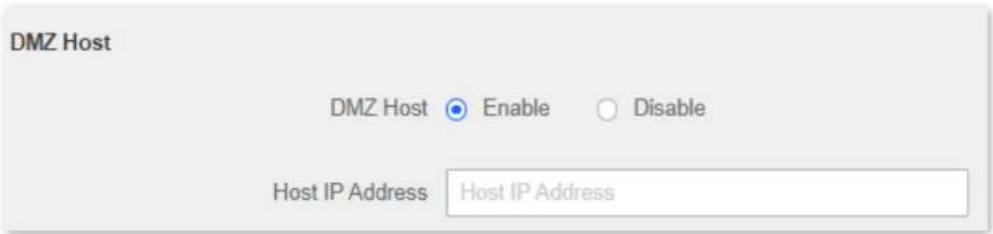
Figure 6-23 DMZ host
Table 6-7 DMZ parameter description
| Parameter | Description |
| DMZ Host | It is used to enable or disable the DMZ function. |
| Host IP Address | It specifies the IP address to be set as the DMZ host. |
6.6.2 Enable internet users to access LAN resources using an IP address
Scenario: You have set up an FTP server within your LAN.
Goal: Open the FTP server to internet users and enable family members who are not at home to access the resources of the FTP server from the internet.
Solution: You can configure the DMZ host function to reach the goal.
Assume that the information of the FTP server includes:
- IP address: 192.168.0.125
- MAC address: 00:00:00:00:00:01
- Service port: 21
- The WAN IP address of the router: X.X.X.X.

Note
Please ensure that the router obtains an IP address from the public network. This function may not work on a host with an IP address of a private network or an intranet IP address assigned by ISPs that start with 100. Common IPv4 addresses are classified into class A, class B and class C. Private IP addresses of class A range from 10.0.0.0 to 10.255.255.255; Private IP addresses of class B range from 172.16.0.0-172.31.255.255; Private IP addresses of class C range from 192.168.0.0-192.168.255.255.
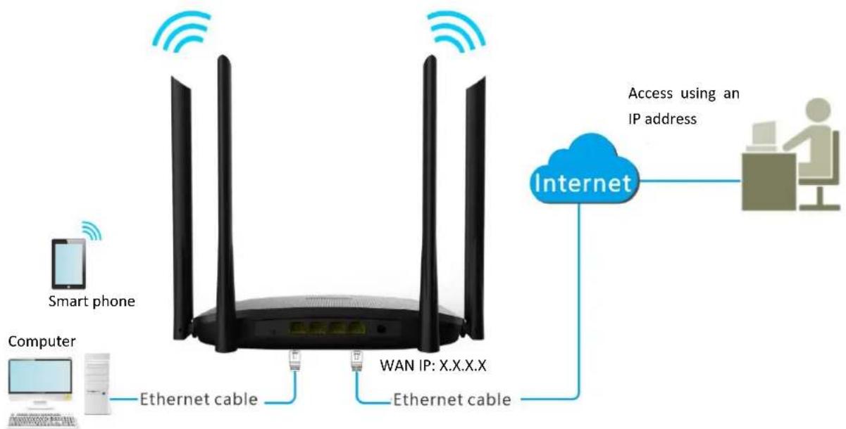
flowchart
graph TD
    A["Smart phone"] -->|Wireless Signal| B["WAN IP: X.X.X.X"]
    C["Computer"] -->|Ethernet cable| B
    D["Internet"] -->|Access using an IP address| E["User at desk"]
    B -->|Ethernet cable| D
Figure 6-24 Application description
— IP: 192.168.0.125
— MAC: 00:00:00:00:00:01
— Port number: 21
Procedures:
Step 1 Launch a web browser on a device connected to the router and visit http://hikvisionwifi.local to log in to the web UI of the router.
Step 2 Set the server host as the DMZ host.
1) Navigate to Advanced > DMZ Host.
2) Set DMZ Host to Enable.
3) Enter the IP address of the host, which is 192.168.0.125 in this example.
4) Click Save at the bottom of the page.
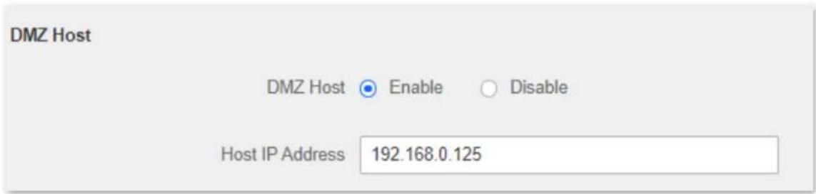
Figure 6-25 Enter the IP address of the host
Step 3 Assign a fixed IP address to the host where the server locates.
1) Navigate to Advanced > IP-MAC Binding.
2) Enter the IP Address for the FTP server host, which is 192.168.0.125 in this example.
3) Enter the MAC Address of the host of the FTP server, which is 00:00:00:00:00:01 in this example.
4) Click .+

Figure 6-26 IP-MAC binding
5) Click Save at the bottom of the page.
When the configurations are completed, users from the internet can access the DMZ host by visiting "Intranet service application layer protocol name://WAN IP address of the router". If the intranet service port number is not the default number, the visiting address should be: "Intranet service application layer protocol name://WAN IP address of the router:intranet service port number".
In this example, the address is "ftp://X.X.X.X". You can find the WAN IP address of the router in View system information.
i Note
When the default intranet service port number is 80, please change the service port number to an uncommon one (1024 to 65535), such as 9999.
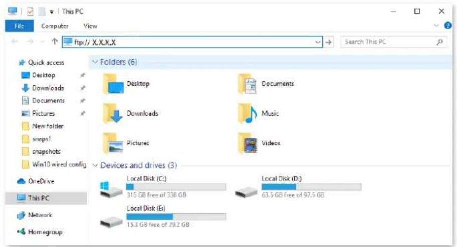
Figure 6-27 Enter the ftp://X.X.X.X
Enter the user name and password to access the resources on the FTP server.
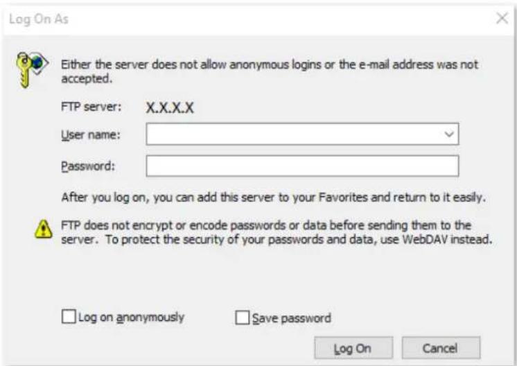
Figure 6-28 Enter the user name and password
If you want to access the server within a LAN using a domain name, refer to the solution DMZ + DDNS.
i Note
After the configuration is completed, if internet users still cannot access the FTP server, close the firewall, antivirus software and security guards on the host of the FTP server and try again.
6.7 UPnP
UPnP is short for Universal Plug and Play. This function enables the router open port automatically for UPnP-based programs. It is generally used for P2P programs, such as BitComet and AnyChat, and helps increase the download speed.
To access the configuration page, log in to the web UI of the router, and navigate to Advanced > UPnP.
This function is enabled by default.

Figure 6-29 UPnP
6.8 Firewall
The firewall function helps the router avoids the host on WAN from Ping the WAN IP address of the router to prevent from exposing itself, and meanwhile protect the router against external Ping attacks.
To access the configuration page, log in to the web UI of the router, and navigate to Advanced > Firewall.
This function is enabled by default.
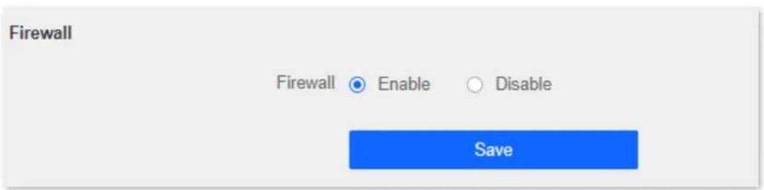
Figure 6-30 Firewall
Chapter 7 Administration
7.1 Login password
To ensure network security, a login password is recommended. We recommend you set a complex login password with more types of characters, such as uppercase letters, lowercase letters, numbers and special characters.
To access the login password configuration page, log in to the web UI and navigate to Administration > Login Password.
When you use the router for the first time, no password is required to log in to the web UI of the router and you can set a login password on this page.
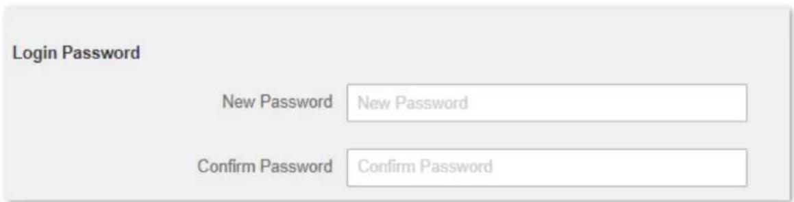
Figure 7-1 Login password
If you have already set a login password, you can change the password on this page, but the old password is required.
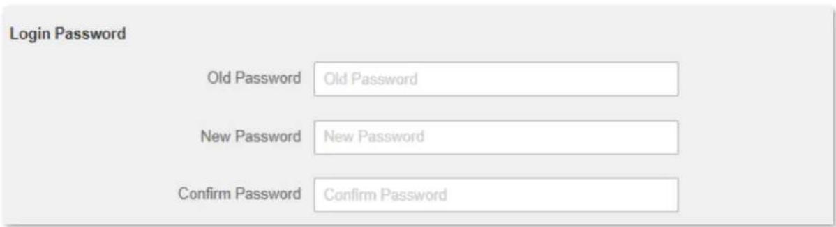
Figure 7-2 Login password
i Note
If you forget your login password and cannot log in to the web UI of the router, refer to Reset the router and log in to the web UI without a password.
7.2 WAN parameters
7.2.1 Change the server name and service name
When the connection type is PPPoE, you may need to set the server name and service name. These parameters provided by your ISP, if any, need to be configured after you have set up your internet connection. Otherwise, keep the default settings.
To access the configuration page, log in to the web UI and navigate to Administration > WAN Parameters.
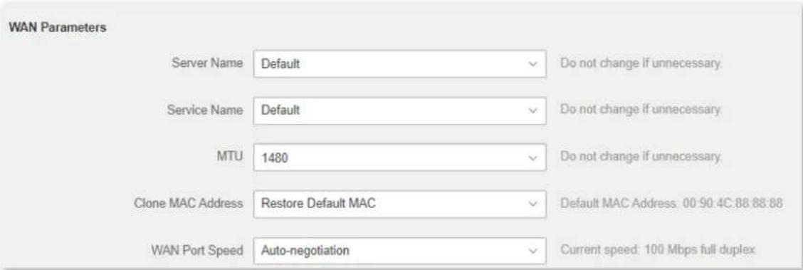
Figure 7-3 WAN parameter
7.2.2 Change the MTU value
MTU (Maximum Transmission Unit) is the largest data packet transmitted by a network device. When the connection type is PPPoE, the default MTU value is 1480. When the connection type is the dynamic IP address or static IP address, the default MTU value is 1500. Do not change the value unless necessary. If you need to, please refer to the following instructions.
To access the configuration page, log in to the web UI of the router, and navigate to Administration > WAN Parameters.
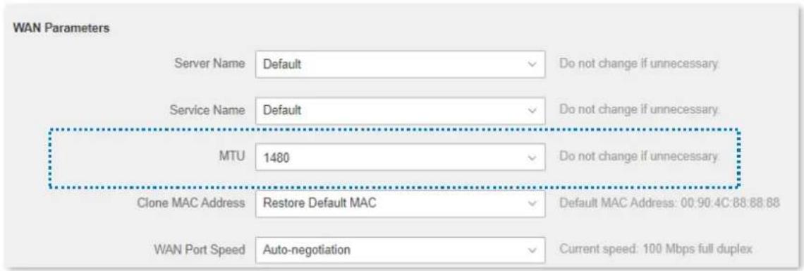
Figure 7-4 Change the MTU value
Generally, the default value is recommended. Try to change the MTU value when:
- You cannot access some specific websites or encrypted websites (such as E-banking or Paypal websites).
- You cannot receive or send Emails or access an FTP or POP server.
You can try reducing the value of MTU gradually from 1500 until the problem is resolved (The recommended range is 1400 to 1500).
Table 7-1 MTU application description
| MTU | Application |
| 1500 | It is commonly used for non-ADSL and non-VPN dial-up connections. |
| 1492, 1480 | It is used for ADSL dial-up connections. |
| 1472 | It is the maximum value for the ping command. A packet with a larger size is fragmented. |
| 1468 | It is used for DHCP connections. |
| 1436 | It is used for VPN or PPTP connections. |
7.2.3 Clone WAN MAC address
If you still cannot access the internet after completing Internet settings, it could be the result of the ISP's configuration to bind the internet account information with a fixed MAC address. In this case, you can clone and change the MAC address of the router to solve the problem.
To access the configuration page, log in to the web UI of the router, and navigate to Administration > WAN Parameters.
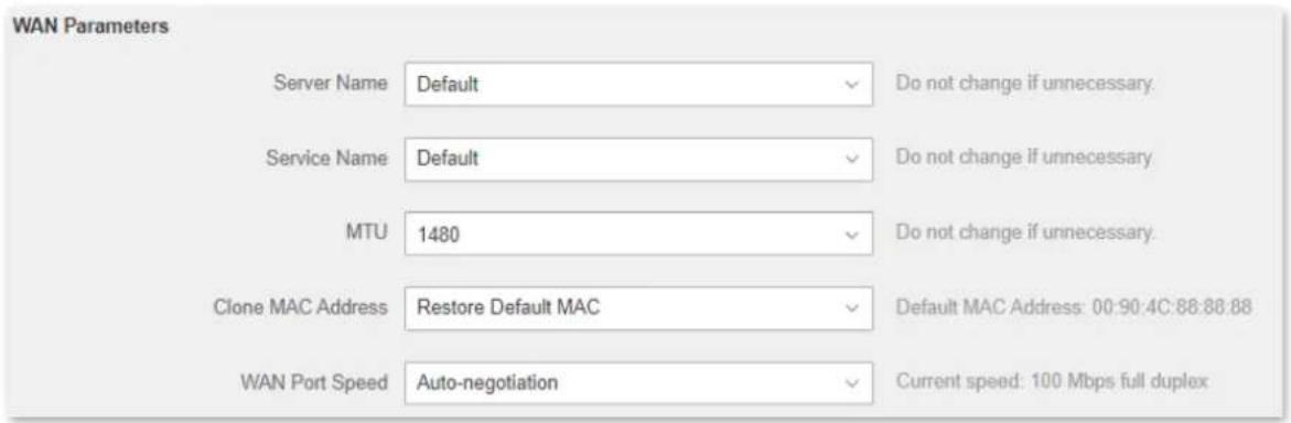
Figure 7-5 Clone WAN MAC address
- Restore Default MAC: Restore the factory setting of the MAC address.
- Clone Local Host MAC: Set the MAC address of the router to the same as that of the device which is configuring the router.
- Manual: Manually set a MAC address.
i Note
Please ensure the cloned MAC address is that of the computer or the router which is already able to access the internet.
Procedures:
Step 1 Launch a web browser on a device connected to the router and visit http://hikvisionwifi.local to log in to the web UI of the router.
Step 2 Navigate to Administration > WAN Parameters.
Step 3 Click the drop-down box of Clone MAC Address, and choose Clone Local Host MAC to copy the MAC address of the management device, or Manual to enter the desired MAC address.
Step 4 Click Save at the bottom of the page.
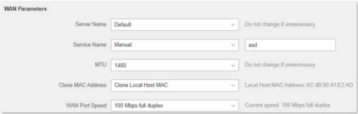
Figure 7-6 Clone WAN MAC address
7.2.4 Change the WAN speed
To access the configuration page, log in to the web UI of the router, and navigate to Administration > WAN Parameters.
When the Ethernet cable is not damaged and connected to the WAN port properly, but Ethernet cable disconnected is still shown on the Internet Settings page, you can try to change the WAN Speed to 10 Mbps full-duplex or 10 Mbps half-duplex to solve the problem. Otherwise, keep the default settings.
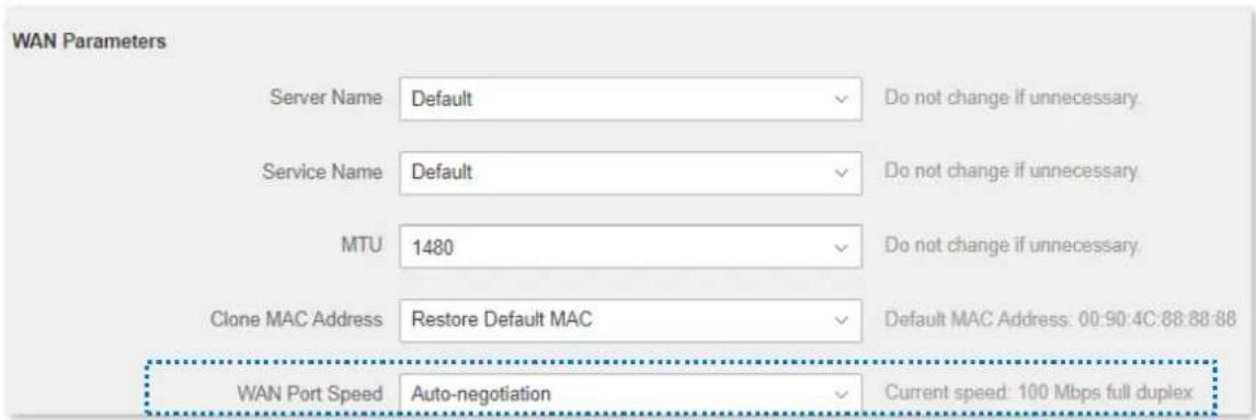
Figure 7-7 Change the WAN speed
Table 7-2 WAN speed parameter description
| WAN Speed | Description |
| Auto-negotiation | It indicates that the speed and duplex mode are determined through the negotiation with the peer port. |
| 100 Mbps full duplex | It indicates that the WAN port is working at the speed of 100 Mbps, and the port can receive and send data packets at the same time. |
| 10 Mbps half duplex | It indicates that the WAN port is working at the speed of 10 Mbps, but the port can only receive or send data packets alternately. |
| 10 Mbps full duplex | It indicates that the WAN port is working at the speed of 10 Mbps, and the port can receive and send data packets at the same time. |
| 100 Mbps half duplex | It indicates that the WAN port is working at the speed of 100 Mbps, but the port can only receive or send data packets alternately. |
7.3 LAN parameters
On this page, you can:
- Change the LAN IP address and subnet mask of the router.
- Change the DHCP server parameters of the router.
The DHCP server can automatically assign an IP address, subnet mask, gateway and other information to clients within the LAN. If you disable this function, you need to manually configure the IP address information on the client to access the Internet. Do not disable the DHCP server function unless necessary.
Configure the DNS information assigned to clients.
To access the configuration page, log in to the web UI of the router, and navigate to Administration > LAN Parameters.
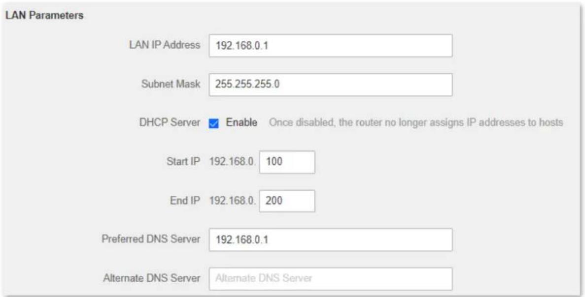
Figure 7-8 LAN parameters
Table 7-3 LAN parameter description
| Parameter | Description |
| LAN IP Address | It specifies the LAN IP address of the router, which is also the management IP address for logging in to the web UI of the router. |
| Subnet Mask | It specifies the subnet mask of the LAN port, used to identify the IP address range of the local area network. |
| DHCP Server | When the DHCP server is enabled, the router automatically assigns an IP address to clients connected to the router |
| Start IP | It specifies the range of IP addresses that can be assigned to devices connected to the router. The default range is 192.168.0.100 to 192.168.0.200. |
| End IP | |
| Preferred DNS Server | It specifies the primary DNS address of the router used to assign to the clients. You can change it if necessary.NoteMake sure that the primary DNS server is the IP address of the correct DNS server or DNS proxy. Otherwise, you may fail to access the internet |
| Alternate DNS Server | It specifies the secondary DNS address of the router used to assign to the clients. It is an optional field and is left blank by default. |
7.4 Remote web management
7.4.1 Overview
Generally, the web UI of the router can only be accessed on devices that are connected to the router by a LAN port or wireless connection. When you encounter a network fault, you can ask for remote technical assistance, which improves efficiency and reduces costs and efforts.
To access the configuration page, log in to the web UI of the router, and navigate to Administration > Remote Web Management.
By default, this function is disabled. When this function is enabled, the page is shown as below.
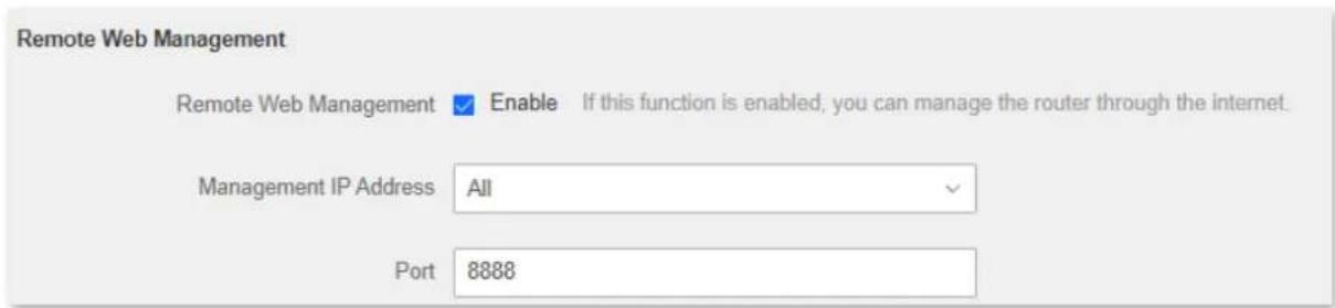
Figure 7-9 Remote web management
Table 7-4 Remote web management parameter description
| Parameter | Description |
| Remote Web Management | It is used to enable or disable the remote management function of the router. |
| Management IP Address | It specifies the IP address of the host which can access the web UI of the router remotely.All: It indicates that hosts with any IP address from the internet can access the web UI of the router. It is not recommended for security.Specific: Only the host with the specified IP address can access the web UI of the router remotely. If the host is under a LAN, ensure that the IP address is the IP address of the gateway of the host (a public IP address). |
| Port | It specifies the port number of the router which is opened for remote management. Change it as required.NoteThe port number from 1 to 1024 has been occupied by familiar services. It is strongly recommended to enter a port number from 1025 to 65535 to prevent conflict.Remote management can be achieved by visiting "http://the WAN IP address of the router:port number". If the DDNS host function is enabled, the web UI can also be accessed through "http://the domain name of the router's WAN port:port number". |
7.4.2 Internet users access the web UI
It specifies the port number of the router which is opened for remote management. Change it as required.
Scenario: You encounter a problem in configuring the router, and the router can access the internet.
Goal: Ask technical support to help you configure the router remotely.
Solution: You can configure the remote management function to reach the goal.
Assume that:
- The IP address of the device that remotely accesses the web UI: 210.76.200.101
- The WAN port IP address of the router: X.X.X.X
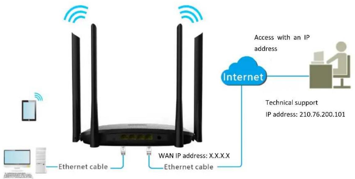
flowchart
graph TD
    A["Router"] -->|Ethernet cable| B["Internet"]
    B --> C["Access with an IP address"]
    B --> D["Technical support IP address: 210.76.200.101"]
    A --> E["Mobile Device"]
    A --> F["Computer"]
    A --> G["Wi-Fi network"]
    style A fill:#f9f,stroke:#333
    style B fill:#ccf,stroke:#333
    style C fill:#cfc,stroke:#333
    style D fill:#fcc,stroke:#333
    style E fill:#ffc,stroke:#333
    style F fill:#cfc,stroke:#333
    style G fill:#fcc,stroke:#333
Figure 7-10 Application scenario
Procedures:
Step 1 Launch a web browser on a device connected to the router and visit http://hikvisionwifi.local to log in to the web UI of the router.
Step 2 Navigate to Administration > Remote Web Management.
Step 3 Tick Enable of Remote Web Management function.
Step 4 Set Management IP Address to Specific, and enter the IP address of the device that remotely accesses the web UI, which is 210.76.200.101 in this example.
Step 5 Enter a port number used to access the router remotely.
Step 6 Click Save at the bottom of the page.
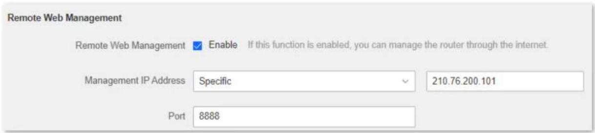
Figure 7-11 Configure management IP address
When the configuration is completed, the technical support can access and manage the router by visiting "http://X.X.X.X:8888" on the computer.
7.5 Date & time
If the system time of the router is incorrect, time-based functions of the router cannot take effect correctly, including the WiFi schedule, parental controls and automatic maintenance functions.
The router supports the synchronization of time with the internet. when the router is connected to the internet, the router will calibrate the system time of the router. You can also set the time zone for your router.
To access the page, log in to the web Ui of the router and navigate to Administration > Date & Time.

Figure 7-12 Date & time
7.6 Device management
7.6.1 Reboot the router
If any parameter fails to take effect or the router does not work properly, you can try rebooting the router.

Rebooting the router will disconnect all connections to the router. Reboot the router during leisure time.
To reboot the router, log in to the web UI of the router and navigate to Administration > Device Management. Click Reboot to reboot the router.
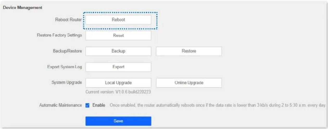
Figure 7-13 Reboot the router
Wait for a moment until the ongoing process finishes. The router reboots successfully.
7.6.2 Reset the router
If you are uncertain about why the internet is inaccessible through the router or you forget the login password of the router, you can reset the router.

Note
- Resetting the router is not recommended unless you cannot find a solution for the current problem anyway. You need to reconfigure the router after it is reset.
- Ensure that the power supply of the router is normal when the router is reset. Otherwise, the router could be damaged.
● The default login IP address is 192.168.0.1 after resetting, and no password is required.
Reset the router using the reset button
Hold down the reset button for about 8 seconds and release it when the LED indicator blinks fast. The router is reset.
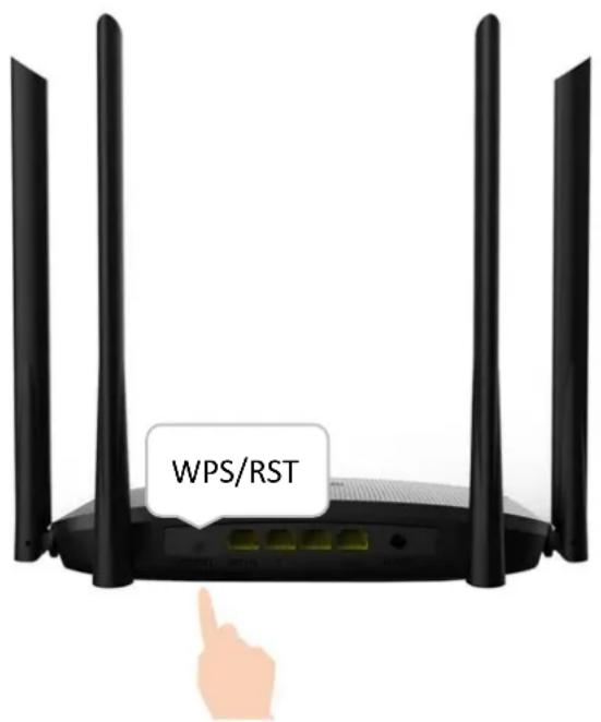
Figure 7-14 Reset the router using the reset button
Reset the router on the web UI
Procedures:
Step 1 Launch a web browser on a device connected to the router and visit http://hikvisionwifi.local to log in to the web UI of the router.
Step 2 Navigate to Administration > Device Management.
Step 3 Click Reset.
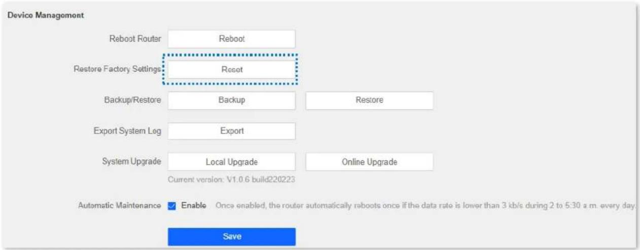
Figure 7-15 Reset the router on the web UI
Step 4 Click OK in the pop-up window.
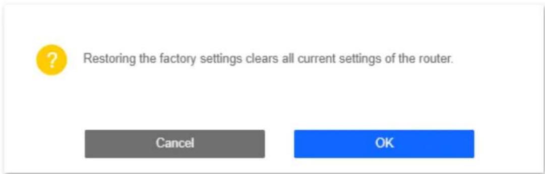
Figure 7-16 Click OK
Wait for a moment until the ongoing process finishes. The router is reset.
7.6.3 Backup/restore configuration
In this module, you can back up the current configurations of the router to your computer. You are recommended to back up the configuration after the settings of the router are significantly changed, or the router works in a good condition.
After you restore the router to factory settings or upgrade it, you can use this function to restore the configurations that have been backed up.
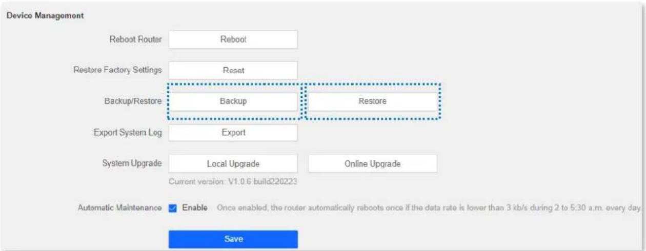
Figure 7-17 Backup/restore configuration
Back up the configurations of the router
Procedures:
Step 1 Launch a web browser on a device connected to the router and visit http://hikvisionwifi.local to log in to the web UI of the router.
Step 2 Navigate to Administration > Device Management.
Step 3 Click Backup.
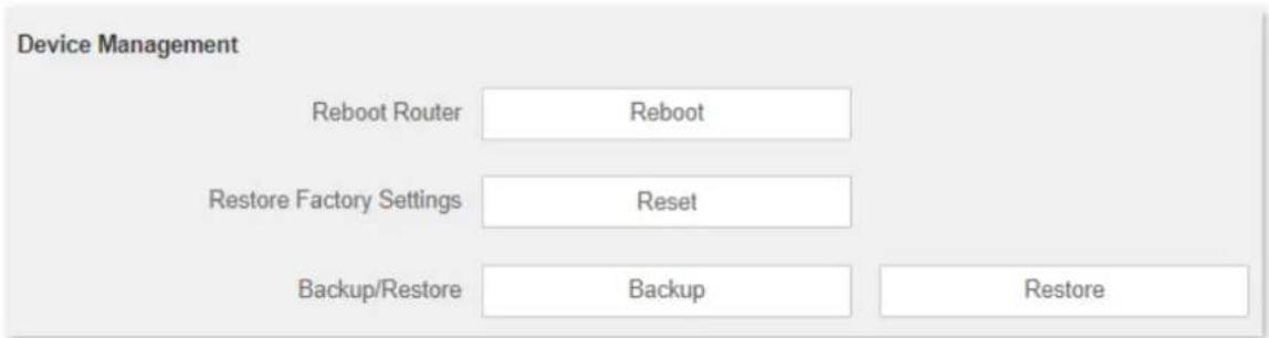
Figure 7-18 Back up the configurations
After the file is downloaded, you can name it RouterCfm.cfg.
Restore previous configurations of the router
Procedures:
Step 1 Launch a web browser on a device connected to the router and visit http://hikvisionwifi.local to log in to the web UI of the router.
Step 2 Navigate to Administration > Device Management.
Step 4 Select the configuration file to be restored (extension: cfg), and click Open.
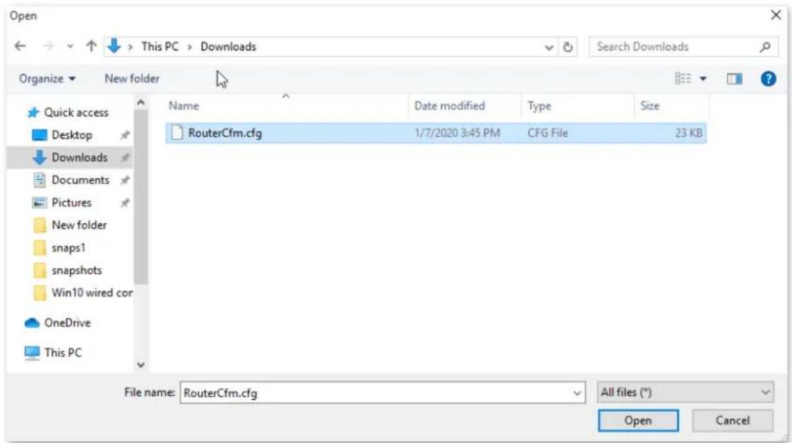
Figure 7-19 Restore previous configurations of the router
Step 5 Click OK in the pop-up window.
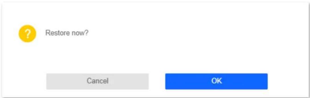
Figure 7-20 Click OK
Wait for a moment until the ongoing process finishes, and the router restores previous settings.
7.6.4 Export system log
This function logs all key events that occur after the router is started. If you encounter a network fault, you can turn to system logs for fault rectification.
To access the configuration page, log in to the web UI of the router, and navigate to Administration > Device Management. Click Export to save the system logs to your local host.
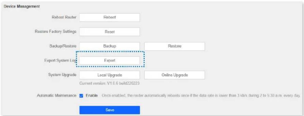
Figure 7-21 Export system log
7.6.5 Upgrade firmware
This function enables the router to obtain the latest functions and more stable performance. The router supports local firmware upgrade.
Local upgrade

Danger
To prevent the router from being damaged:
● Ensure that the firmware applies to the router.
- It is recommended to upgrade the firmware by connecting a LAN port to a computer and performing the upgrade on the web UI.
- When you are upgrading the firmware, do not power off the router.
Procedures:
Step 1 Go to www.hikvision.com/en. Download an applicable firmware of the router to your local computer and unzip it.
Step 2 Launch a web browser on a device connected to the router and visit http://hikvisionwifi.local to log in to the web UI of the router.
Step 3 Navigate to Administration > Device Management.
Step 4 Click Local Upgrade.
Step 5 Click the firmware file downloaded previously (extension: bin), and click Open.
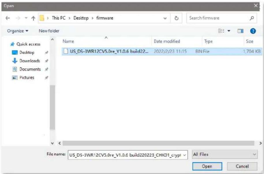
Figure 7-22 Local upgrade
Step 6 Click OK.
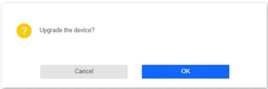
Figure 7-23 Click OK
Wait for a moment until the ongoing process finishes. Log in to the web UI of the router again. Navigate to Administration > Device Management and check whether the upgrade is successful based on the Current Firmware Version.
i Note
For better performance of the new firmware, you are recommended to reset the router to factory default settings and re-configure the router when the upgrading is completed.
7.6.6 Automatic maintenance
Automatic maintenance enables you to make the router restart regularly. It helps improve the stability and service life of the router.
To configure the automatic maintenance function, navigate to Administration > Device Management.
When this function is enabled, from 02:00 to 05:30 every day in the morning, if there is any user connected to the router and the traffic over the router's WAN port exceeds 3 KB/s within 30 minutes, the router will delay rebooting. If there is any user connected to the router and the traffic over the WAN port does not exceed 3 KB/s within 30 minutes, or there is no user connected to the router and the traffic over the router's WAN port is slower than 3 KB/s within 3 minutes, the router will reboot automatically.
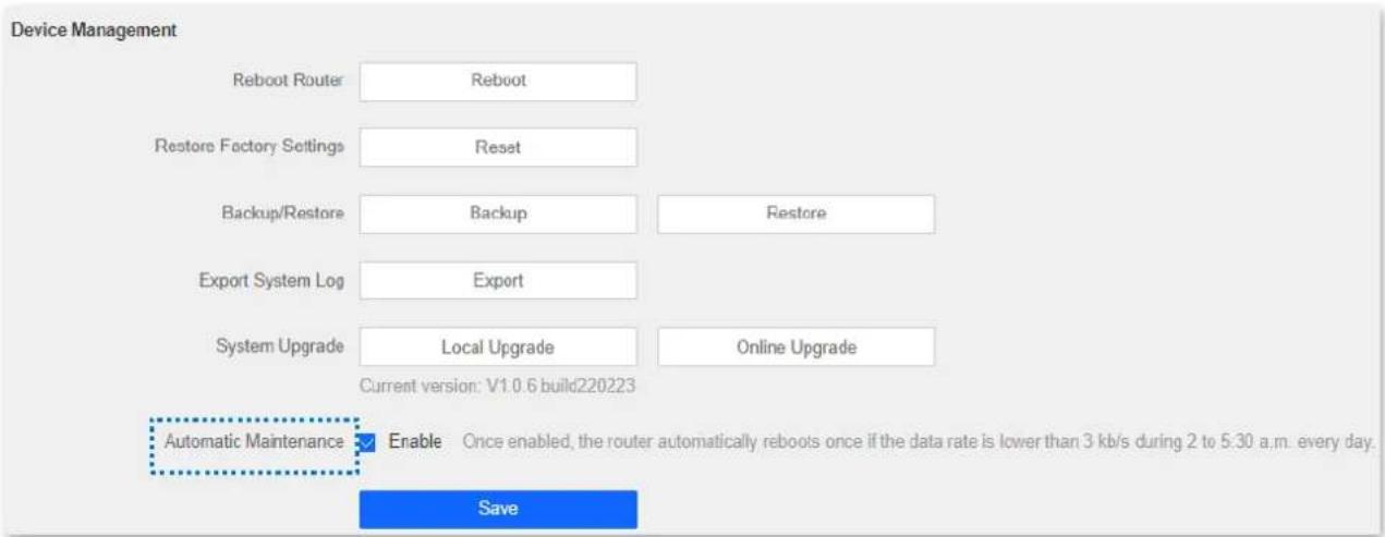
Figure 7-24 Automatic maintenance
Appendix A
A.1 Configuring the computer to obtain an IPv4 address automatically
Perform the Configuring procedures corresponding to Windows 10, Windows 8 and Windows 7 as required. A computer installed with a wired network adapter is used as an example to describe the procedures. The procedures for configuring computers installed with a WiFi network adapter are similar.
A.1.1 Windows 10
Step 1 Click in the bottom right corner of the desktop and choose Network settings.

Figure 7-25 Network settings
Step 2 Click Change adapter options.
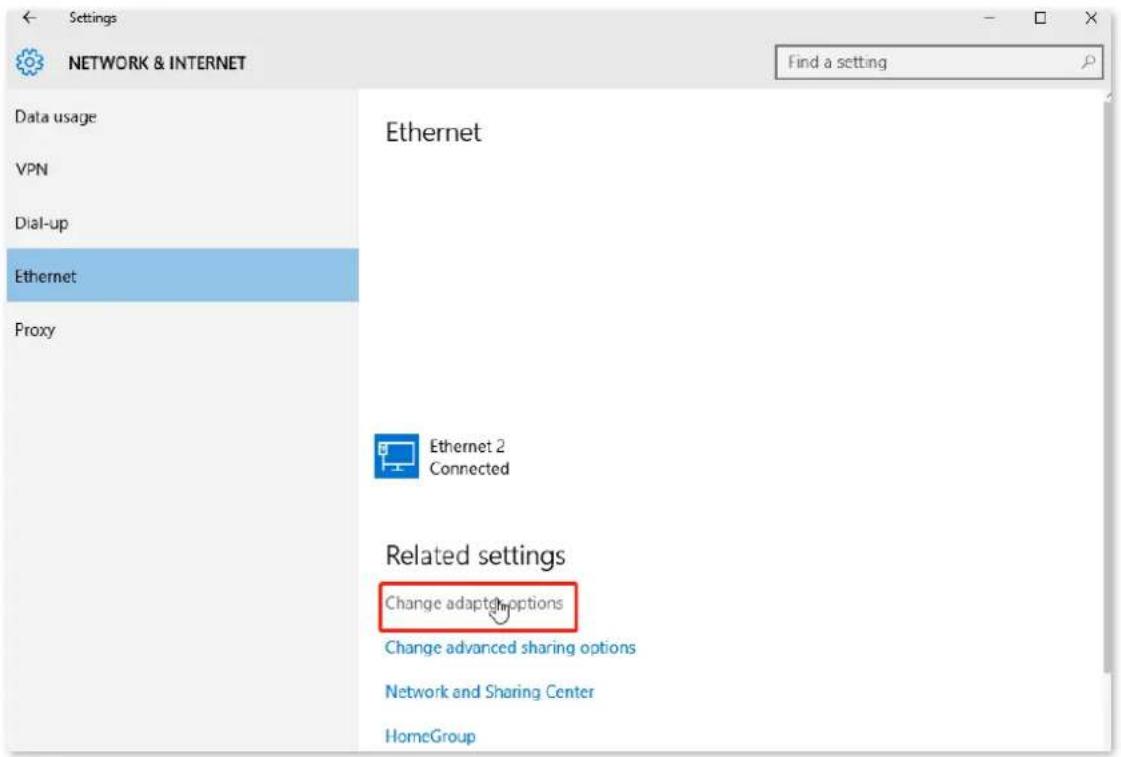
Figure 7-26 Click Change adapter options
Step 3 Right-click on the connection which is being connected, and then click Properties.
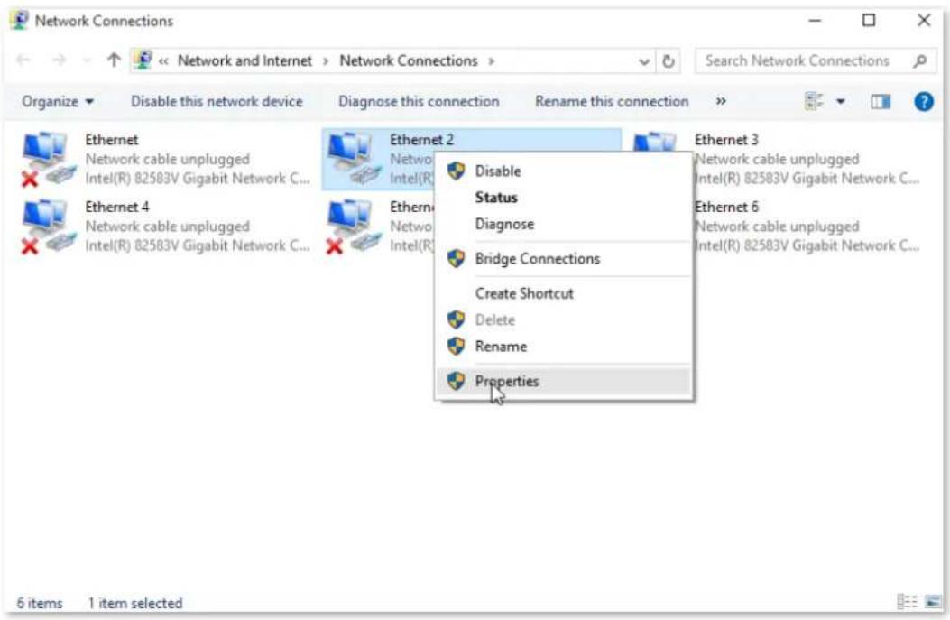
Figure 7-27 Click properties
Step 4 Double-click Internet Protocol Version 4 (TCP/IPv4).
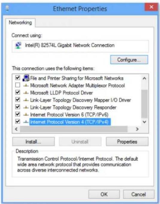
Figure 7-28 Click Internet Protocol Version 4(TCP/IPv4)
Step 5 Select Obtain an IP address automatically and Obtain DNS server address automatically, and click OK.
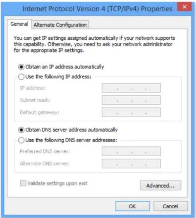
Figure 7-29 Click OK
Step 6 Click Close in the Ethernet Properties window.
A.1.2 Windows 8
Step 1 Right-click in the bottom right corner of the desktop and choose Open Network and Sharing Center.
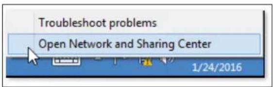
Figure 7-30 Choose Open Network and Sharing Center
Step 2 Click Ethernet and then Properties.
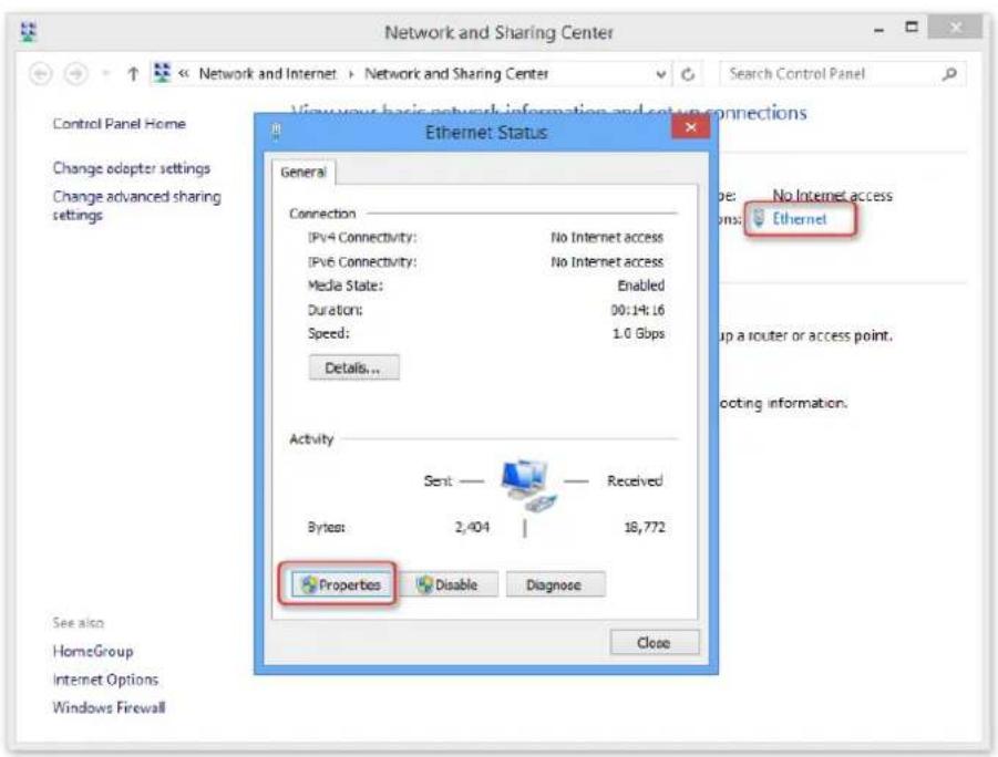
Figure 7-31 Click Ethernet and then Properties
Step 3 Double-click Internet Protocol Version 4 (TCP/IPv4).
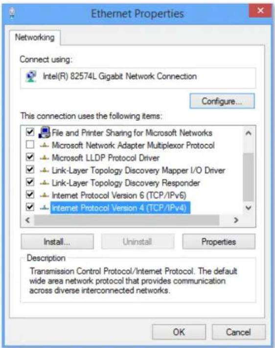
Figure 7-32 Double-click Internet Protocol Version 4(TCP/IPv4)
Step 4 Select Obtain an IP address automatically and Obtain DNS server address automatically, and click OK.
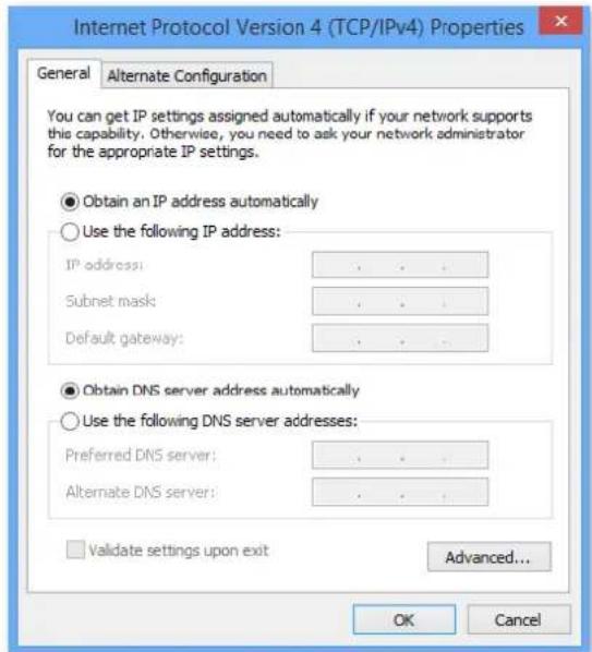
Figure 7-33 Click OK
Step 5 Click OK in the Ethernet Properties window.
A.1.3 Windows 7
Step 1 Click in the bottom right corner of the desktop and choose Open Network and Sharing Center.
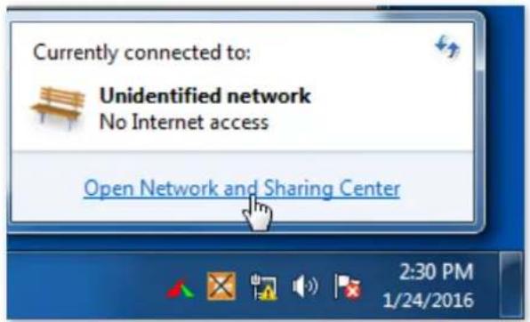
Figure 7-34 Choose Open Network and Sharing Center
Step 2 Click Local Area Connection and then Properties.
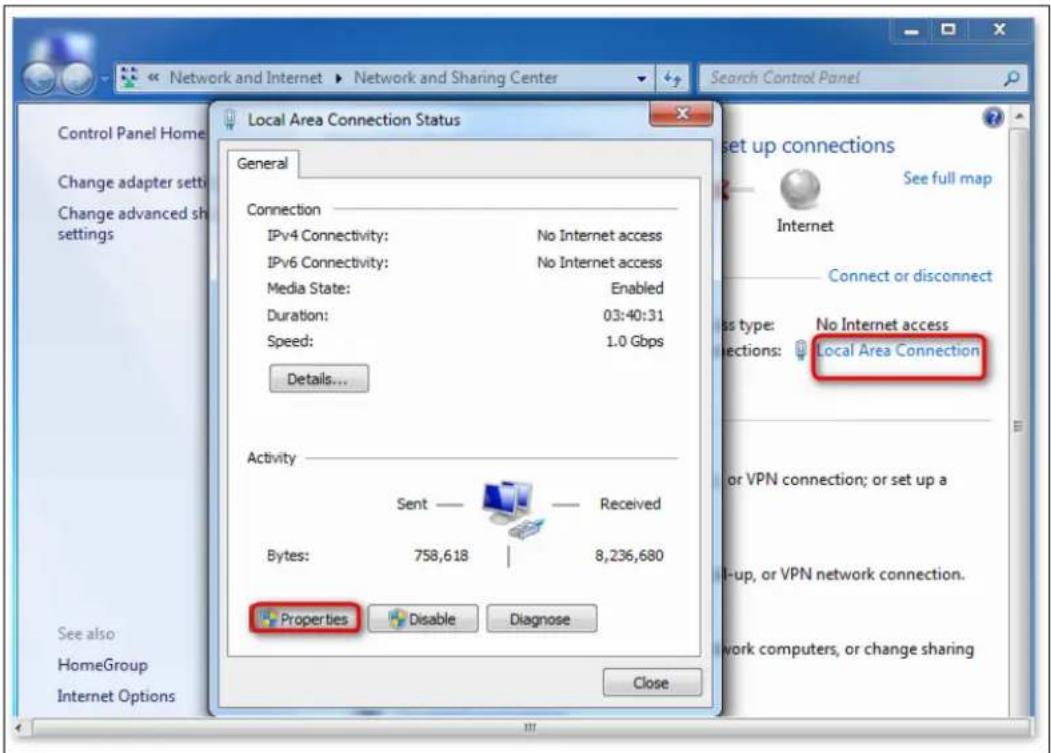
Figure 7-35 Click Local Area Connection and then Properties
Step 3 Double-click Internet Protocol Version 4 (TCP/IPv4).
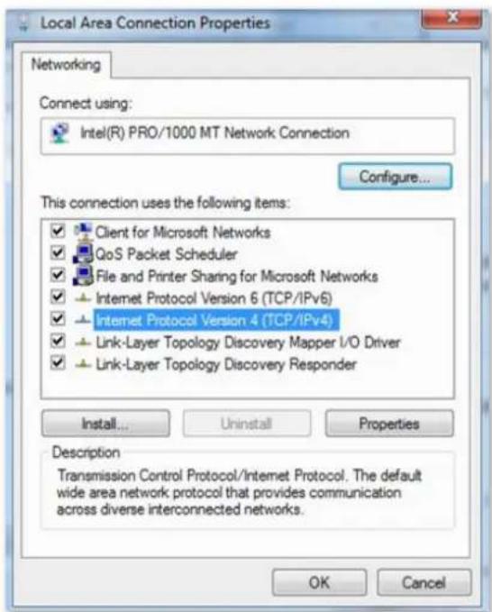
Figure 7-36 Double-click Internet Protocol Version 4 (TCP/IPv4)
Step 4 Select Obtain an IP address automatically and Obtain DNS server address automatically, and click OK.
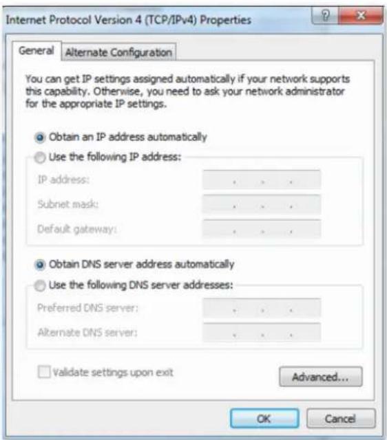
Figure 7-37 Click OK
Step 5 Click OK in the Local Area Connection Properties window.
A.2 Default parameters
Table 7-5 Parameter
| Parameter | Default | |
| Login | IP Address | 192.168.0.1 |
| Password | None | |
| LAN Parameter | IP Address | 192.168.0.1 |
| Sunnet Mask | 255.255.255.0 | |
| DHCP Server | DHCP Server | Enabled |
| Start IP Address | 192.168.0.100 | |
| End IP Address | 192.168.0.200 | |
| Preferred DNS Server | 192.168.0.1 | |
| Wireless Settings | WiFi Name | See the label on the bottom of the router |
| WiFi Password | None | |
| Unify 2.4 GHz & 5 GHz | Enabled | |
| Guest Network | Disabled | |
| Beamforming | Enabled | |
| IPv6 | Disabled | |
A.3 Acronyms and abbreviations
Table 7-6 Acronyms and abbreviations
| Abbreviations | Full spelling |
| AES | Advanced Encryption Standard |
| AP | Access Point |
| DDNS | Dynamic Domain Name Server |
| DHCP | Dynamic Host Configuration Protocol |
| DHCPv6 | Dynamic Host Configuration Protocol for IPv6 |
| DMZ | Demilitarized Zone |
| DNS | Domain Name System |
| GMT | Greenwich Mean Time |
| IP | Internet Protocol |
| IPv4 | Internet Protocol version 4 |
| IPv6 | Internet Protocol version 6 |
| LAN | Local Area Network |
| MAC | Medium Access Control |
| MIMO | Multiple Input Multiple Output |
| MTU | Maximum Transmission Unit |
| NAT | Network Address Translation |
| TCP | Transmission Control Protocol |
| UDP | User Datagram Protocol |
| UPnP | Universal Plug and Play |
| WAN | Wide Area Network |
| WISP | Wireless Internet Service Provider |
| WPA-PSK | WPA-Preshared Key |

See Far, Go Further
- About this Manual
- Trademarks
- Disclaimer
- Regulatory Information
- FCC Information
- FCC Compliance
- FCC Conditions
- EU Conformity Statement
- Industry Canada ICES-003 Compliance
- Symbol Conventions
- Safety Instructions
- TABLE OF CONTENTS
- Chapter 1 Get to know your device....1
- Chapter 2 Web UI....5
- Chapter 3 Status....10
- Chapter 4 Route settings....18
- Chapter 5 Client management ....75
- Chapter 6 Advanced....84
- Chapter 7 Administration....110
- Appendix A 130
- Chapter 1 Get to know your device
- Overview
- Note
- Appearance
- LED indicator
- Jack, ports, and button
- Label
- HIKVISION®
- Wireless Router
- Chapter 2 Web UI
- Log in to the web UI
- Log out of the web UI
- Web UI layout
- i Note
- Common element
- Chapter 3 Status
- View internet connection status
- Procedures:
- View online device information
- View system information
- Chapter 4 Route settings
- Internet settings
- Overview
- Serve as a router
- Set up a PPPoE connection
- Internet Connection
- Set up a static IP connection
- Set up a dynamic IP connection
- Serve as a WiFi extender
- Method 1: Set the router to WISP mode
- Caution
- Method 2: Set the router to universal relay mode
- Serve as an AP
- Wireless settings
- WiFi name and password
- Overview
- Separate the 2.4 GHz WiFi name from 5 GHz Wi-Fi name
- Change the WiFi name and WiFi password
- Step 6 Click Save at the bottom of the page.
- Hide the WiFi network
- Connect to a hidden WiFi network
- Guest network
- Set up the guest network
- WiFi signal strength
- WiFi parameters
- Beamforming
- WPS
- Connect to the WiFi network using the WPS button
- Connect to the WiFi network using the PBC button
- Connect to the WiFi network using the PIN code
- Step 1 Find the PIN code.
- IPv6 configuration
- Connect to the IPv6 network of ISPs
- PPPoEv6
- Access the internet through PPPoEv6
- IPv6 network test:
- DHCPv6
- Static IPv6
- Access the internet through static IPv6
- IPv6 LAN setup
- IPv6 status
- Sleeping mode
- LED control
- Danger
- WiFi schedule
- Chapter 5 Client management
- Access control
- Overview
- Set the upload and download speed limit
- Add the device to the blacklist
- Remove the device from the blacklist
- Parental control
- Overview
- An example of configuring parental control
- Chapter 6 Advanced
- MAC address filter
- Overview
- Only allow specified device to access the internet
- Step 6 Click
- IPTV
- Overview
- Watch IPTV program through the router
- 5) Click OK.
- Step 2 Set the set-top-box.
- IP-MAC binding
- Overview
- Assign fixed IP addresses to LAN clients
- Port mapping
- Overview
- Enable internet users to access LAN resources using an IP address
- DDNS
- Overview
- Enable internet users to access LAN resources using a domain name
- DMZ host
- Overview
- Enable internet users to access LAN resources using an IP address
- UPnP
- Firewall
- Chapter 7 Administration
- Login password
- WAN parameters
- Change the server name and service name
- Change the MTU value
- Clone WAN MAC address
- Change the WAN speed
- LAN parameters
- Remote web management
- Overview
- Internet users access the web UI
- Date & time
- Device management
- Reboot the router
- Reset the router
- Reset the router using the reset button
- Reset the router on the web UI
- Backup/restore configuration
- Back up the configurations of the router
- Restore previous configurations of the router
- Export system log
- Upgrade firmware
- Local upgrade
- Automatic maintenance
- To configure the automatic maintenance function, navigate to Administration > Device Management.
- Appendix A
- A.1 Configuring the computer to obtain an IPv4 address automatically
- A.1.1 Windows 10
- A.1.2 Windows 8
- A.1.3 Windows 7
- A.2 Default parameters
- A.3 Acronyms and abbreviations
Brand : Hikvision
Model : AC1200
Category : Router