S-150 - Ice Maker Servend - Free user manual and instructions
Find the device manual for free S-150 Servend in PDF.


| Product Type | Ice and Beverage Dispenser |
| Brand | Servend (Manitowoc Foodservice) |
| Model Number | S-150 |
| Manual Part Number | STH14 |
| Dimensions (A x B x C) | 24.81 in x 23.00 in x 9.94 in |
| Overall Height (G) | 31.13 in |
| Footprint (Min x Max) | 17.81 in x 19.00 in |
| Valve Height (C) | 9.94 in (with Flomatic valves) |
| Power Supply | 115 V, 60 Hz or 220-240 V, 50/60 Hz |
| Ice Dispensing Type | Paddle wheel with agitator |
| Beverage Dispensing | Post-mix or pre-mix, carbonated and non-carbonated |
| Carbonation | Internal or external carbonator (optional) |
| Cleaning Frequency | Daily: drain pan, valves; Monthly: ice bin sanitization |
| Safety Features | Grounding required, CO2 ventilation, electrical disconnect before service |
| Warranty Information | Consult local distributor; excludes brixing, cleaning, adjustments |
| Serial Number Location | On serial number decal affixed to dispenser |
| Required Clearance (Ice Machine) | 6 in on all sides |
| Water Supply Pressure | Minimum 40 psi dynamic, maximum 65 psi static |
| CO2 Pressure (Post-mix) | 60-80 psi for BIB pumps; carbonator: 75 psi (cold), 90-105 psi (ambient) |
| Operating Temperature Range | 50°F to 95°F (10°C to 35°C) |
Frequently Asked Questions - S-150 Servend
User questions about S-150 Servend
0 question about this device. Answer the ones you know or ask your own.
Ask a new question about this device
Download the instructions for your Ice Maker in PDF format for free! Find your manual S-150 - Servend and take your electronic device back in hand. On this page are published all the documents necessary for the use of your device. S-150 by Servend.
USER MANUAL S-150 Servend
natural_image
Exterior view of a modern beverage tap with multiple side payers (no visible text or symbols)Servend Ice & Beverage Dispensing Units
Technician's Handbook
This manual is updated as new information and models are released. Visit our website for the latest manual. www.manitowocfsg.com
Leader in Ice & Beverage Dispensers
Part Number STH14 9/10
Safety Notices
As you work on Manitowoc equipment, be sure to pay close attention to the safety notices in this handbook. Disregarding the notices may lead to serious injury and/or damage to the equipment.
Throughout this handbook, you will see the following types of safety notices:

Warning
Text in a Warning box alerts you to a potential personal injury situation. Be sure to read the Warning statement before proceeding, and work carefully.

Caution
Text in a Caution box alerts you to a situation in which you could damage the equipment. Be sure to read the Caution statement before proceeding, and work carefully.
Procedural Notices
As you work on Manitowoc equipment, be sure to read the procedural notices in this handbook. These notices supply helpful information which may assist you as you work.
Throughout this handbook, you will see the following types of procedural notices:
Important
Text in an Important box provides you with information that may help you perform a procedure more efficiently. Disregarding this information will not cause damage or injury, but it may slow you down as you work.
NOTE: Text set off as a Note provides you with simple, but useful, extra information about the procedure you are performing.
Read These Before Proceeding:
Caution
Proper installation, care and maintenance are essential for maximum performance and trouble-free operation of your Manitowoc equipment. If you encounter problems not covered by this handbook, do not proceed, contact Manitowoc Foodservice Group. We will be happy to provide assistance.
Important
Routine adjustments and maintenance procedures outlined in this handbook are not covered by the warranty.
Warning
PERSONAL INJURY POTENTIAL
Do not operate equipment that has been misused, abused, neglected, damaged, or altered/modified from that of original manufactured specifications.
We reserve the right to make product improvements at any time. Specifications and design are subject to change without notice.
Table of Contents
General Information
Model Numbers 9
How to Read a Model Number ..... 9
Dispensing Basics 10
Accessories 13
Serial Number Location 15
Warranty Information .....15
Installation
General 17
Dimensions 18
Pre-installation Checklist .....31
Location 33
Drains 34
Water Supply ....38
Setting Pressures 39
Component Identification
Typical Systems .....43
System Components 46
Ice/Beverage and Counter Electric
Dispensers 53
Maintenance
Cleaning 55
Disassembly ....59
Replacement 79
Sanitizing 82
Shipping, Storage and Relocation .....87
Operation
Blade Tower Brixing 89
CEV Electronic Ice & Carbonation Control 90
Flavor Magic Programming .....93
Flav'R-Pic External Programming ..... 97
Flav'R-Pic (FRP-250) Programming ....100
Flav'R-Pic (FRP-250) Brixing Procedure 105
FlexTower Programming Modes .....115
Adjustments 120
Agitation Timer 124
Troubleshooting
Checklist 125
Liquid Level Control 137
Diagnosing a Defective Carbonator .... 138
Component Specifications
Electrical Requirements 139
Minimum Circuit Ampacity ..... 139
Grounding Instructions ..... 141
Pump Deck Wiring 143
Water Supply 144
Charts
Flavor Magic Logic Matrix ..... 147
Flav'R-Pic (FRP-250) Logic Matrix ..... 150
Diagrams
Blade Tower Plumbing 153
CEV-30i & CEV-30e Plumbing ..... 156
CEV-40i & CEV-40e Plumbing ..... 158
CT-6 Plumbing and Wiring 160
CT-8 Plumbing and Wiring 161
CF-1522 Plumbing 162
DI-1522 Post-mix Plumbing 164
DI-1522 Pre-mix Plumbing 164
DI/DIL-2323 6 Valve Post-mix Plumbing 165
DI/DIL-2323 8 Valve Post-mix Plumbing &
Variety Valve 166
DI/DIL-2323 10 Valve Post-mix Plumbing 167
DI/DIL-2323 6 Valve Pre-mix Plumbing . 168
Flavor Magic Plumbing 169
FRP-250 Plumbing Diagram ..... 170
FRP-250 & FRP-250SCI Tubing Layout . 171
FT-8 Plumbing 172
FT-12 Plumbing 172
FlexTower Water Recirculation Pump Flow
173
FlexTower Water Chiller Flow ..... 173
MDH-302 12 Valve Plumbing ..... 174
MDH-402 16 Valve Plumbing ..... 175
MDH-402 20 Valve Plumbing .....176
S/SV150 6 Valve Diagram .....177
S/SV175 8 Valve Diagram .....177
S/SV200/250/SV-250QD 8 Valve Diagram 178
S/SV200/250 10 Valve Diagram .....178
Flex Manifold Diagrams .....180
CEV Wiring 181
CF Drop-In Series Wiring .....187
Drop-in Wiring .....188
Flavor Magic Wiring 192
Flav'R-Pic (FRP-250) Wiring 193
FlexTower Wiring 195
MDH-302 & MDH-402 Wiring .....199
NGF-250 Wiring 201
quickdraw Wiring 202
S/SV/SVi Wiring 203
Selectable Ice Wiring .....205
This Page Intentionally Left Blank
General Information
Model Numbers
This manual covers the following models:
| CEV-30j CEV-30e CEV-30i | |
| CEV-40e CEV-40i CT-6 | |
| CT-8 DI-1522 DI-2323 | |
| DIL-2323 FRP-250 FRP-250SCI | |
| FT-8 FT-12 FT-16 | |
| M-15 M-45 M-90 | |
| MDH-302 MDH-402 MDH-302CI | |
| MDH-302SCI MDH-402CI MDH-402SCI | |
| NGF-250 | NGF-250QD S-150 |
| S-200 S-250 SV-150 | |
| SV-175 | SV-200 SV-250 |
| SV-150i | SV-175i SV-200i |
| SV-250i | SV-250QD SV-200SCI |
| SV-250SCI | BLADE TOWER FLAVOR MAGIC |
How to Read a Model Number
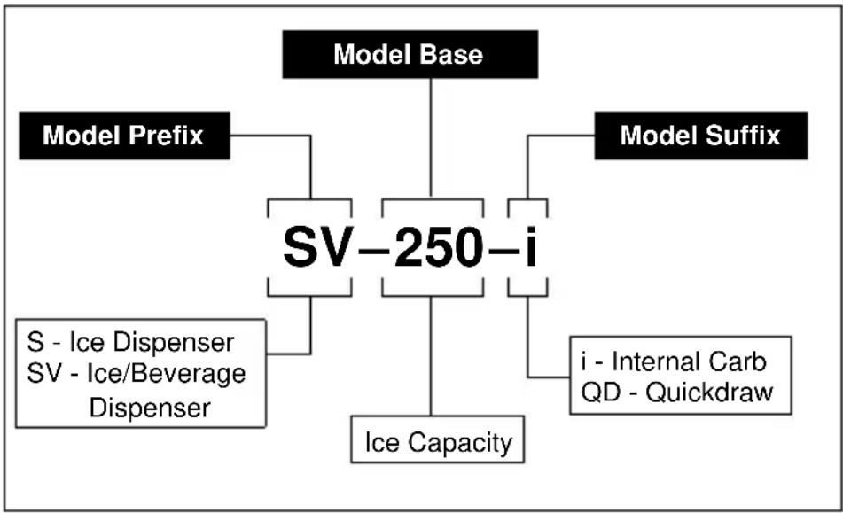
flowchart
graph TD
    A["Model Base"] --> B["SV-250-i"]
    C["Model Prefix"] --> B
    D["Model Suffix"] --> B
    E["S - Ice Dispenser\nSV - Ice/Beverage\nDispenser"] --> B
    F["i - Internal Carb\nQD - Quickdraw"] --> B
    G["Ice Capacity"] --> B
Manitowoc Foodservice developed this manual as a reference guide for the service agent and installer of fountain equipment.
Fountain dispensing is the serving of a beverage (soft drink, tea, or juice, etc.) from a dispenser that will chill the product to an acceptable serving temperature for the consumer.
The beverage, delivery system and dispenser can be postmix or premix. The system may be an elaborate system with most of the components in the back of the store and the dispenser in the front. Fountain systems could be a simple system with the complete system under the counter where the dispenser is located.
Our goal is that this manual will remove some of the confusion, and mystery of beverage dispensing equipment while providing a general overview of service to the equipment.
Dispensing Basics
WHAT IS CARBONATION
Carbonation is the process of mixing carbon dioxide gas into a liquid (water). The resulting liquid is called soda water or carbonated water. The carbon dioxide gas is the bubbles you see when a carbonated beverage (like soda) is dispensed.
Most cola, lemon-lime products, etc. are carbonated. Normally teas, juices, etc. are noncarbonated.
Some beverage technicians refer to noncarbonated water as sweet water.
WATER CHARACTERISTICS
Water makes up over 80% of the typical finished beverage. The quality of this primary ingredient is of utmost importance. You should use regular cold tap water, not water that has been through a water softener, conditioner, etc. Any off taste or color should be treated by proper water filtration.
WATER FILTERS
It is recommended that proper water filters treat the water supply for the beverages. There are two basic filters commonly in use.
- Pre-filter, or sand filter. This filter removes any foreign matter from the water down to 25 microns in size.
- Carbon or activated charcoal filter is also used. This filter will reduce chlorine and other chemicals, off-taste and odor. Some of the higher quality filters may reduce organic compounds (bacteria) in the water.
Do not use a filter containing any type of phosphate on the beverage system. Phosphate as used for scale reduction will cause the beverage to lose its carbonation and become “flat” quickly.
WATER PRESSURES
Dynamic (flowing) water pressures to most carbonators should be a minimum of 40 PSI (1.38 bar). Water pressure to dispensers for noncarbonated beverages should be a minimum of 50 pounds (22.7 kg). These pressures are minimum operating pressures, not static pressure.
SYRUP BASICS
Your concentrated syrup containers should be stored in a cool dry location that is easily accessible. Any extremes in temperature can wreak havoc with the quality of the product. For best results, the syrup should be maintained in an environment between 40° and 90°F (4.4° and 32.2°C).
PREMIX
Premix fountain dispensing consists of a container of beverage ready for dispensing, beverage delivery system, carbon dioxide ( CO_2 ) propellant, beverage cooling system, and dispenser. We shall discuss each component of this type of system within the context of this manual.
The major advantage of a premix system over most other types is its flexibility. This flexibility is the ability to go anywhere. Many premix systems will operate without electric power or separate water supply.
POSTMIX
Postmix fountain dispensing consists of either a tank (called a Figal) or a box (called a Bag-in-Box) of beverage syrup. The postmix system will also include the carbonator, fresh water supply, carbon dioxide (CO_2) supply, syrup delivery system, beverage cooling system, and dispenser. We shall discuss each component of this type of system within the context of this manual.
The major advantage of the postmix system over most other systems is the very low cost of delivering a high quality, fresh beverage to the consumer utilizing less floor and storage space for the quantity of beverages served.
PIPING
The fountain system is connected together by a series of tubing or hoses. This tubing is called beverage tube and is commonly available in 1/4" (0.64 cm), 3/8" (0.95 cm), and 1/2" (1.27 cm) inside diameters. Beverage tubing is a flexible, high-pressure tubing. This tubing is capable of withstanding system pressures in excess of 100 PSI (6.9 bar). The beverage tubing may be an individual line or assembled with many lines of tubing bundled together.
The beverage tubing is attached to the various components of the system with barbed stems, nuts, tees, etc. The tubing is held onto the fittings with small tube clamps called stepless (Oetiker®) clamps. When attaching the tubing and fitting to a “flared” fitting, the use of a flare washer is required.
Several different types of tubing are available for the beverage industry. If there is any possibility of the tubing laying in a damp environment, the use of non-permeable tubing should be used. Tubing is also available as a single tube or bundled together. Single tube is available as non-permeable plastic or stainless steel. Bundled tube is available as plastic only.
Accessories
BAFFLE FOR MANITOWOC® ICE MACHINES
When installing a Manitowoc Ice Machine on a dispenser, a baffle kit is required for proper installation. The baffle kit is designed to prevent ice from lying against the front of the ice machine, and melting down the front of the dispenser. There are two different baffle kits available for "S" series ice machines, one kit is for the 30" (76.2 cm) wide machine, and the other kit is for the 22" (55.9 cm) wide machine. There is also a kit for "Q" series ice machines.
Kits are available through your local distributor. List prices may be subject to change without notification. Please call your local parts distributor for current pricing before ordering.
NOTE: For full information about ice machine installation, including plumbing lines connections and electrical requirements, see the ice machine installation manual.
MANUAL FILL LID FOR DISPENSERS WITH AN ICE MACHINE
If you are top mounting your dispenser with an ice machine, you will require a lid for the manual fill area at the top, front of the dispenser.
If you ordered a dispenser and an ice machine at the same time, the manual fill lid may be included with the unit. The manual fill lid can be ordered from your local distributor.
LEGS
Legs are optional equipment with most MBE dispensers. Standard legs are 4" (10.2 cm) tall stainless steel legs. We do not recommend using legs
when an ice machine is mounted on the dispenser. The combined weight of the dispenser, ice and ice machine is more evenly distributed when the base area of the dispenser is in contact with the countertop.
Serial Number Location
This number is required when requesting information from your local distributor. The serial number is listed on the SERIAL NUMBER DECAL affixed to the dispenser.
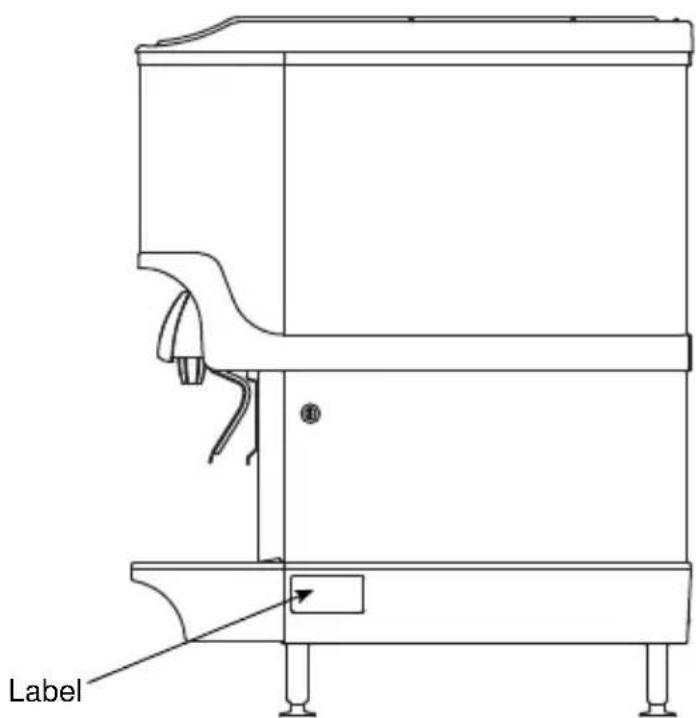
Serial Number Location
Warranty Information
Consult your local MBE Distributor for terms and conditions of your warranty. Your warranty specifically excludes all beverage valve brixing, general adjustments, cleaning, accessories and related servicing.
Your warranty card must be returned to MBE to activate the warranty on this equipment. If a warranty card is not returned, the warranty period can begin when the equipment leaves the MBE factory.
No equipment may be returned to MBE without a written Return Materials Authorization (RMA).
Equipment returned without an RMA will be refused at MBE's dock and returned to the sender at the sender's expense.
Please contact your local MBE distributor for return procedures.
This Page Intentionally Left Blank
Installation
General
These instructions are provided to assist the qualified installer. Contact your Manitowoc Beverage Equipment Service Agent or call Manitowoc Beverage Equipment for information regarding start-up services.
Important
Failure to follow these installation guidelines may affect warranty coverage.
Dimensions
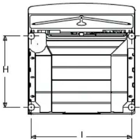
ICE/BEVERAGE & COUNTER ELECTRIC DISPENSER DIMENSIONS
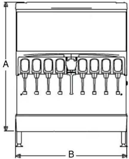
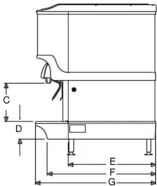
natural_image
Technical line drawing of a mechanical device with dimension labels H and l (no text or symbols present)Note: Graphic above is for illustration purposes only, and may not look like your unit.
| MODEL A | B C* D E F G H I | ||||||||
| CEV-30 29 | 88"(75.9 cm) | 20.50"(52.7 cm) | 11.76"(29.8 cm) | 4.44"(11.3 cm) | N/A N/A | 25.75" | (65.4 cm) | 17.00"(43.1 cm) | 17.50"(44.4 cm) |
| CEV-40 29 | 88"(75.9 cm) | 26.00"(66.0 cm) | 11.76"(29.8 cm) | 4.44"(11.3 cm) | N/A N/A | 25.75" | (65.4 cm) | 17.00"(43.1 cm) | 23.00"(58.4 cm) |
| M-45 24.25 | 5"(61.6 cm) | 15.00"(38.10 cm) | 9.75"(24.8 cm) | 4.44"(11.3 cm) | 17.88"(45.4 cm) | 26.37"(67.0 cm) | 28.00"(71.1 cm) | 19.37"(49.2cm) | 12.75"(32.4 cm) |
| M-90 32.0 | 0"(81.30 cm) 15.00" | (38.10 cm) | 9.75"(24.8 cm) | 4.44"(11.3 cm) | 18.00"(45.7 cm) | 26.37"(67.0 cm) | 28.00"(71.1 cm) | 19.37"(49.2cm) | 12.75"(32.4 cm) |
| MDH-302(SCI) | 33.00" / 44.00" w/EMerch(83.8 cm / 111.7 cm) | 42.75"(108.5 cm) | 9.94"(17.6 cm) | 4.44"(11.3 cm) | 22.50"(57.2 cm) | 28.00"(71.1 cm) | 30.50"(77.4 cm) | 20.50"(52.0 cm) | 38.75"(98.4 cm) |
| MDH-402(SCI) | 32.00" / 44.00" w/EMerch1 /54.00" w/EMerch2(81.2 cm / 111.7 cm 137.1 cm) | 60.00"(152.4 cm) | 9.94"(17.6 cm) | 4.44"(11.3 cm) | 22.50"(57.2 cm) | 28.00"(71.1 cm) | 30.50"(77.4 cm) | 21.25"(54.0 cm) | 56.50"(143.6 cm) |
| S/SV-150 24.81" | (63.0 cm) | 23.00"(58.4 cm) | 9.94"(17.6 cm) | 4.44"(11.3 cm) | 22.63"(57.5 cm) | 28.00"(71.1 cm) | 31.13"(79.1 cm) | 20.00"(50.8 cm) | 20.44"(51.9 cm) |
| S/SV-175 24.81" | (63.0 cm) | 23.00"(58.4 cm) | 9.94"(17.6 cm) | 4.44"(11.3 cm) | 22.63"(57.5 cm) | 28.00"(71.1 cm) | 31.13"(79.1 cm) | 20.00"(57.0 cm) | 22.44"(57.0 cm) |
| S/SV-200 34.81" | (88.4 cm) | 30.00"(76.2 cm) | 9.94"(17.6 cm) | 4.44"(11.3 cm) | 22.63"(57.5 cm) | 28.00"(71.1 cm) | 31.13"(79.1 cm) | 20.00"(50.8 cm) | 27.44"(69.7 cm) |
| S/SV/FRP/NGF-250(QD & SCI) | 39.81"(101.1 cm) | 30.00"(76.2 cm) | 9.94"(17.6 cm) | 4.44"(11.3 cm) | 22.63"(57.5 cm) | 28.00"(71.1 cm) | 31.13"(79.1 cm) | 20.00"(50.8 cm) | 27.44"(67.9 cm) |
* C = Valve height using Flomatic Valves.
DROP-IN & CT DIMENSIONS
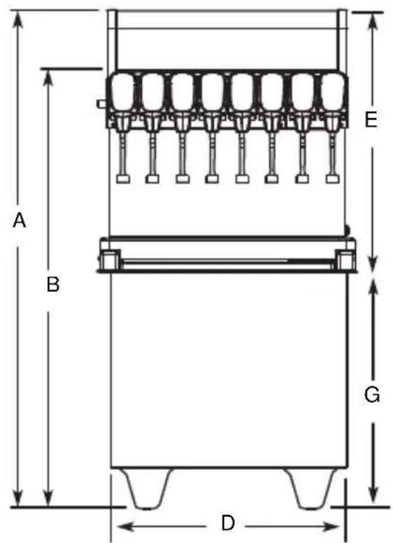
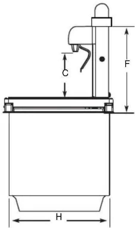
| MODEL A | B | C* | D | E | F | G | H | ||||
| CT-6 N/A | N/A | 9.50" | (24.2 cm) | 14.25"(36.2 cm) | 17.00"(43.2 cm) | 16.38"(42.8 cm) | |||||
| CT-8 N/A | N/A | 9.50" | (24.2 cm) | 15.50"(39.8 cm) | 25.00"(63.5 cm) | 23.75"(60.4 cm) | |||||
| DI-1522 | 44.38"(112.8 cm) | 38.38"(97.5 cm) | 9.50"(24.2 cm) | 15.00"(38.2 cm) | 22.38"(56.9 cm) | 16.38"(42.8 cm) | 22.00"(55.9 cm) | ||||
| DI/DIL-2323 | 56.75"(144.2 cm) | 46.75"(118.8 cm) | 9.50"(24.2 cm) | 23.00"(58.5 cm) | 33.75"(85.8 cm) | 23.75"(60.4 cm) | 23.00"(58.5 cm) |
FLEXTOWER DIMENSIONS
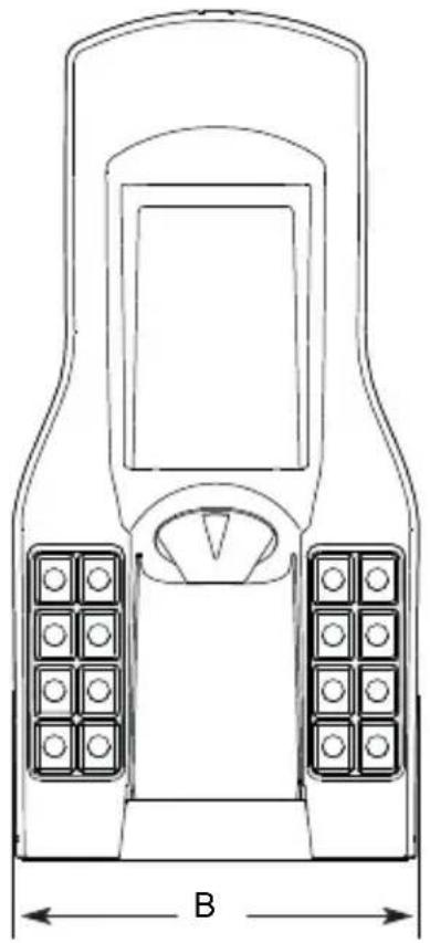
natural_image
Line drawing of a mobile phone control panel with labeled dimensions (B) and buttons, no text or symbols present.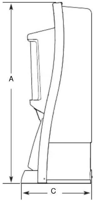
| MODEL A B C | |||
| FT-8/12/16 36.00" | (91.5 cm) | 14.00"(35.6 cm) | 9.50"(24.2 cm) |
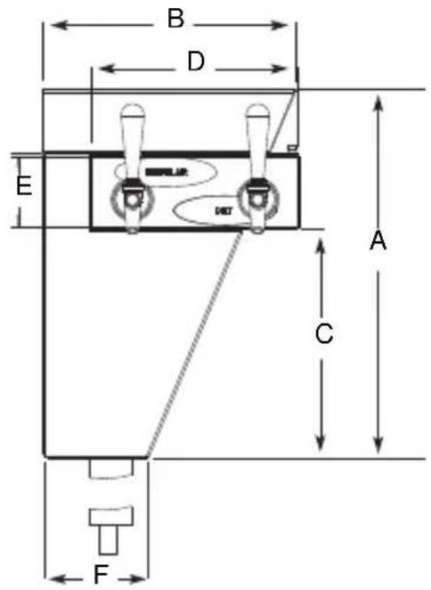
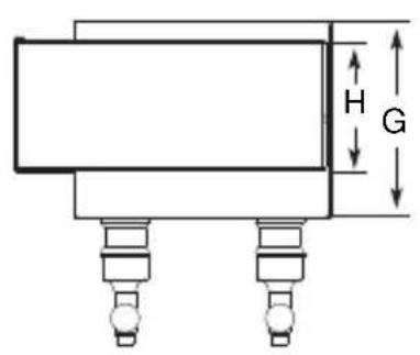
BLADE TOWER DIMENSIONS
| MODEL A B C D | ||||
| BLADETOWER | 17.30"(44.0 cm) | 11.86"(30.2 cm) | 10.75"(27.3 cm) | 9.68"(24.6 cm) |
| E | F | G | H | |
| 3.29"(8.4 cm) | 4.88"(12.4 cm) | 7.39"(18.8 cm) | 5.00"(12.7 cm) | |
ICE/BEVERAGE & COUNTER ELECTRIC DISPENSER FOOTPRINTS
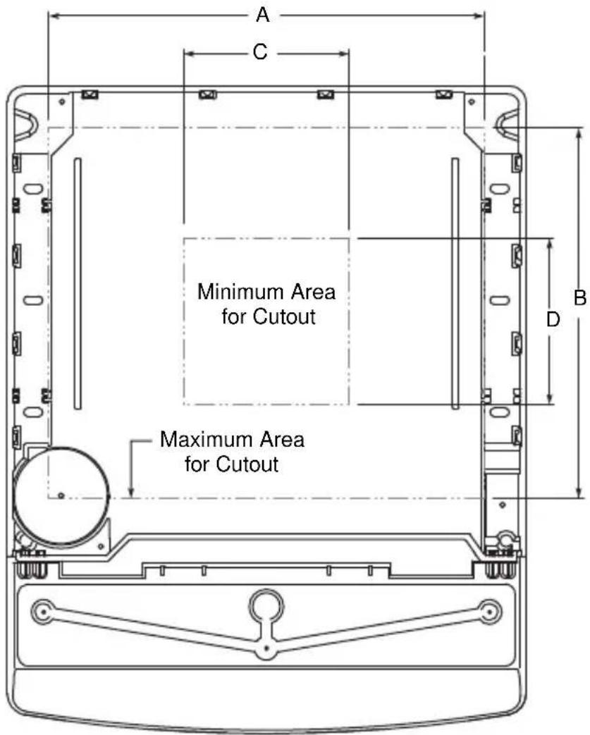
NOTE: Footprint above is for illustration purposes only, and may not look like the bottom of your unit.
| MODEL | Maximum Minimum | C | D | |
| A | B | |||
| CEV-30 14.50"(36.8 cm) | 12.50"(31.7 cm) | 8.00"(20.3 cm) | 8.00"(20.3 cm) | |
| CEV-40 20.00"(50.8 cm) | 12.50"(31.7 cm) | 8.00"(20.3 cm) | 8.00"(20.3 cm) | |
| M-45 8.00"(20.3 cm) | 12.00"(30.5 cm) | 8.00"(20.3 cm) | 12.00"(30.5 cm) | |
| M-90 8.00"(20.3 cm) | 12.00"(30.5 cm) | 8.00"(20.3 cm) | 12.00"(30.5 cm) | |
| MDH-302* 36.75"(93.3 cm) | 20.50"(52.1 cm) | 8.00"(20.3 cm) | 12.00"(30.5 cm) | |
| MDH-402* 38.75"(98.4 cm) | 20.50"(52.1 cm) | 8.00"(20.3 cm) | 12.00"(30.5 cm) | |
| S/SV-150 19.00"(48.3 cm) | 17.81"(45.2 cm) | 8.00"(20.3 cm) | 8.00"(20.3 cm) | |
| S/SV-175 21.00"(53.3 cm) | 17.81"(45.2 cm) | 8.00"(20.3 cm) | 8.00"(20.3 cm) | |
| S/SV-200& 250** | 26.00"(66.0 cm) | 17.81"(45.2 cm) | 8.00"(20.3 cm) | 8.00"(20.3 cm) |
* Includes models ending in SCI
** Includes NGF, FRP, and models ending in QD or SCI
Warning
Cutting the countertop may decrease its strength. Counter must be braced to support the dispenser countertop weight plus ice storage capacity and weight of ice machine, if applicable.
DROP-IN & CT FOOTPRINTS
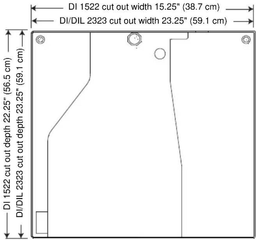
DI/DIL-1522 & 2323
CT-6
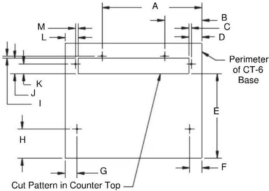
| A | B | C | D | E |
| 12.375"(31.43 cm) | 4.625"(11.75 cm) | 0.313"(0.80 cm) | 1.625"(4.13 cm) | 10.50"(26.67 cm) |
| F | G | H | I | J |
| 1.50"(3.81 cm) | 1.50"(3.81 cm) | 3.625"(9.21 cm) | 0.25"(0.64 cm) | 1.938"(4.92 cm) |
| K | L | M | ||
| 1.188"(3.02 cm) | 1.625"(4.13 cm) | 0.313"(0.80 cm) |
CT-8
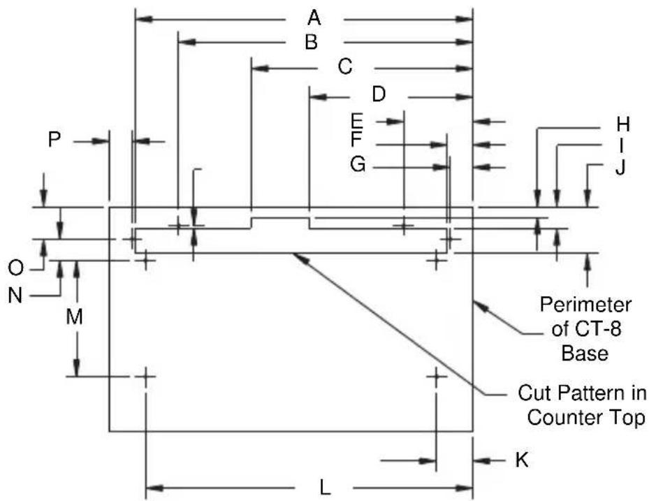
| A | B | C | D |
| 23.25"(59.1 cm) | 20.25"(51.44 cm) | 15.25"(38.74 cm) | 11.25"(28.58 cm) |
| E | F | G | H |
| 4.75"(12.07 cm) | 1.75"(4.45 cm) | 1.56"(3.96 cm) | 0.75"(1.91 cm) |
| I | J | K | L |
| 1.50"(3.81 cm) | 3.25"(8.26 cm) | 2.50"(6.35 cm) | 22.50"(57.15 cm) |
| M | N | O | P |
| 8.00"(20.32 cm) | 1.47"(3.73 cm) | 2.25"(5.72 cm) | 1.56"(3.96 cm) |
FLEXTOWER FOOTPRINT
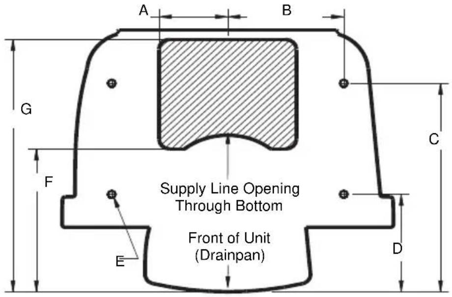
| A | B | C | D |
| (2X) 3.407"(8.65 cm) | (2X) 5.75"(14.61 cm) | (2X) 11.265"(28.61 cm) | (2X) 5.265"(13.37 cm) |
| E | F | G | |
| (4X) ∅ 0.25"(0.64 cm) | 7.701"(19.56 cm) | 13.627"(34.61 cm) |
NOTE: The FlexTower must be secured to the countertop using the four holes provided in the base of the unit and using the hardware provided. Follow customer guidelines for placement of the unit or approximately 10 inches (25.4 cm) from the edge of the counter. A mounting template is provided which is printed on the shipping carton. NOTE: DO NOT DISCARD SHIPPING CARTON UNTIL MOUNTING TEMPLATE IS REMOVED.
| A | B | C | D | E |
| 4.50"(11.43 cm) | 4.00"(10.16 cm) | 0.25"(0.64 cm) | 2.43"(6.17 cm) | ∅ 0.218"(0.55 cm)(4 places) |
| F | G | H | I | |
| 2.50"(6.35 cm) | 4.00"(10.16 cm) | 1.00"(2.54 cm) | 7.55"(19.18 cm) | 15.13"(38.43 cm) |
| K | L | M | ||
| 4.82"(12.24 cm) | 5.38"(13.67 cm) | 6.38"(16.21 cm) |
Pre-installation Checklist
TOP MOUNTED ICE MACHINE INSTALLATIONS
☐ Location — Avoid placing the dispenser and/or ice machine near heat sources such as radiators, ovens, and direct sunlight.
Clearances — Six inch (15.2 cm) clearance on all sides of the icemaker is needed.
Front of icemaker to be flush with front of dispenser — The front of the icemaker must be flush with the front of the dispenser. When the icemaker is flush with the front of the dispenser, some icemakers may overhang at the back of the dispenser.
Drains — A separate drain line is required for the ice machine, in addition to a drain line for the ice/beverage dispenser.
☐ Dispensers may require an adapter kit to install some top-mounted icemakers. Contact your local distributor for the correct adapter kit.
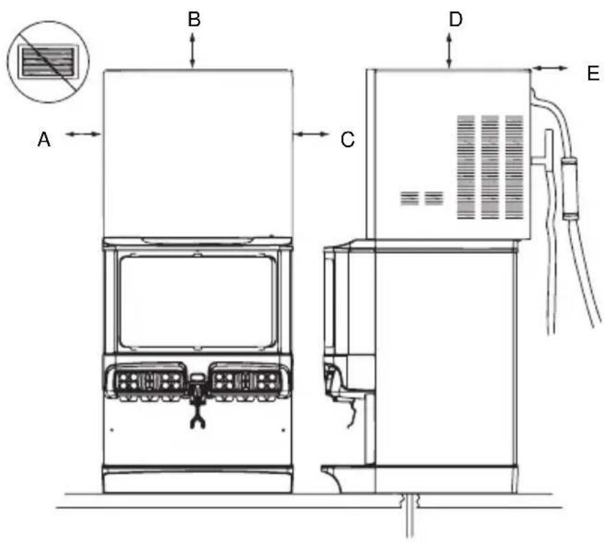
| A | B | C | D | E |
| 6"(15.2 cm) | 6"(15.2 cm) | 6"(15.2 cm) | 6"(15.2 cm) | 6"(15.2 cm) |
For full information about icemaker installation, including plumbing lines connections and electrical requirements, see the icemaker installation manual.
Location
The location selected for the beverage dispenser must meet the following criteria. If any of these criteria are not met, select another location.
- The air temperature must be at least 50^ (10°C), but must not exceed 95^ (35°C).
- The location must not be near heat-generating equipment or in direct sunlight and must be protected from weather.
- The countertop must be level. Verify that the countertop can support the weight of the dispenser, or the dispenser/ice machine combination plus the weight of the stored ice.
- Water lines, drains and power outlet must be within 6' (1.8 m) of location.

Warning
Carbon Dioxide (CO 2 ) displaces oxygen. Exposure to a high concentration of CO 2 gas causes tremors, which are followed rapidly by loss of consciousness and suffocation. If a CO 2 gas leak is suspected, particularly in a small area, immediately ventilate the area before repairing the leak. CO 2 lines and pumps must not be installed in an enclosed space. An enclosed space can be a cooler or small room or closet. This may include convenience stores with glass door self serve coolers. If you suspect CO 2 may build up in an area, venting of the B-I-B pumps and/or CO 2 monitors must be utilized.
Drains
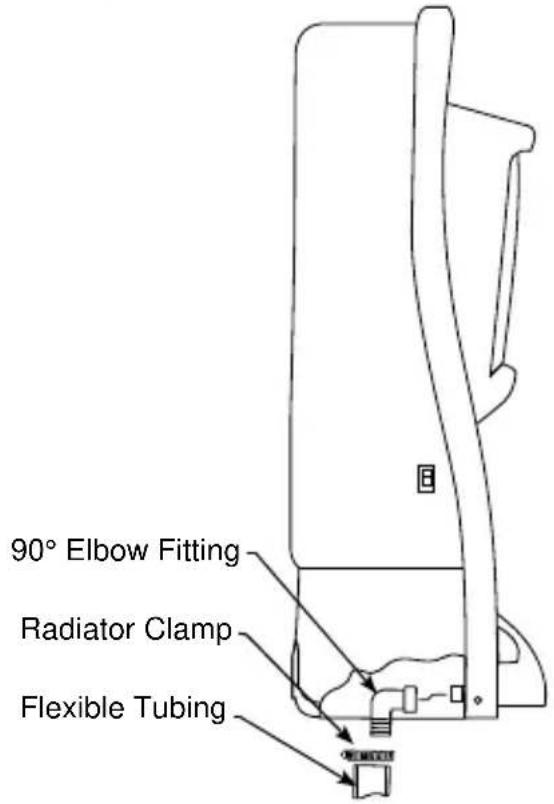
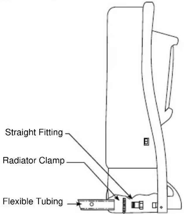
ICE & ICE/BEVERAGE DISPENSER DRAINS
Drainage Through Bottom
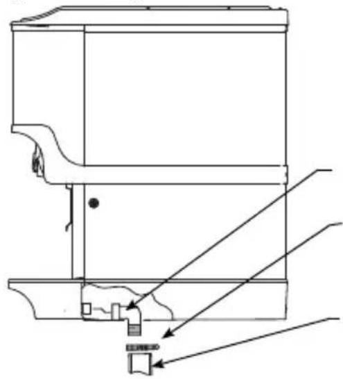
natural_image
Technical line drawing of a mechanical assembly with no visible text or symbols90° Elbow Fitting
Radiator Clamp
Flexible Tubing
Drainage Through Back
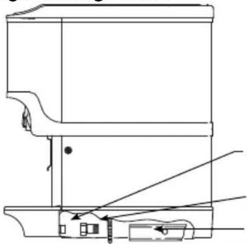
natural_image
Technical line drawing of a mechanical assembly with no visible text or symbolsStraight Fitting
Radiator Clamp
Flexible Tubing
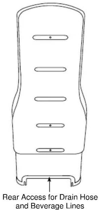
Rear View
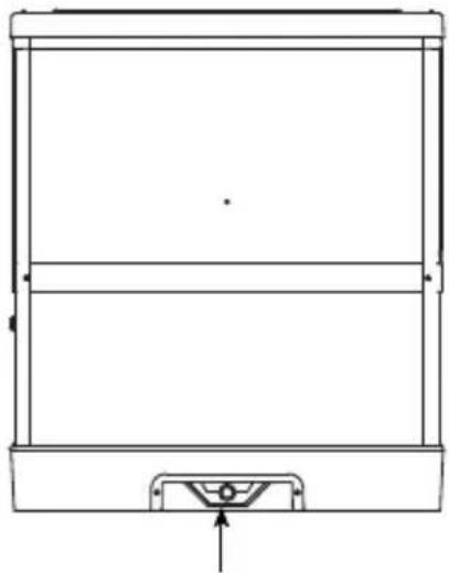
natural_image
Technical line drawing of a rectangular frame with a base and top, showing internal structure and an arrow pointing to the bottom (no text or symbols)Rear Access for Drain Hose and Beverage Lines
FLEXTOWER DRAIN
Drainage Through Bottom
Drainage Through Back
Rear View
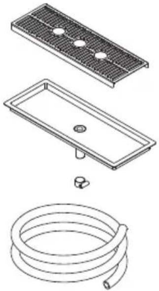
BLADE TOWER DRAIN
natural_image
Technical line drawings of a roof drain, a rectangular basin, and a coiled hose (no text or symbols)Flush Mount Drain — 020001388
natural_image
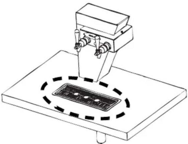
Technical line drawing of a mechanical device with a circular base and mounting base (no text or symbols)NOTE: The Blade Tower can be set up to use an existing drain or an optional drain can be ordered for use with the tower. The illustration above shows the optional flush mount drain setup (Part Number 020001388). If using the optional flush mount drain, be sure to plumb according to local codes.
Water Supply
RECOMMENDED PLUMBING
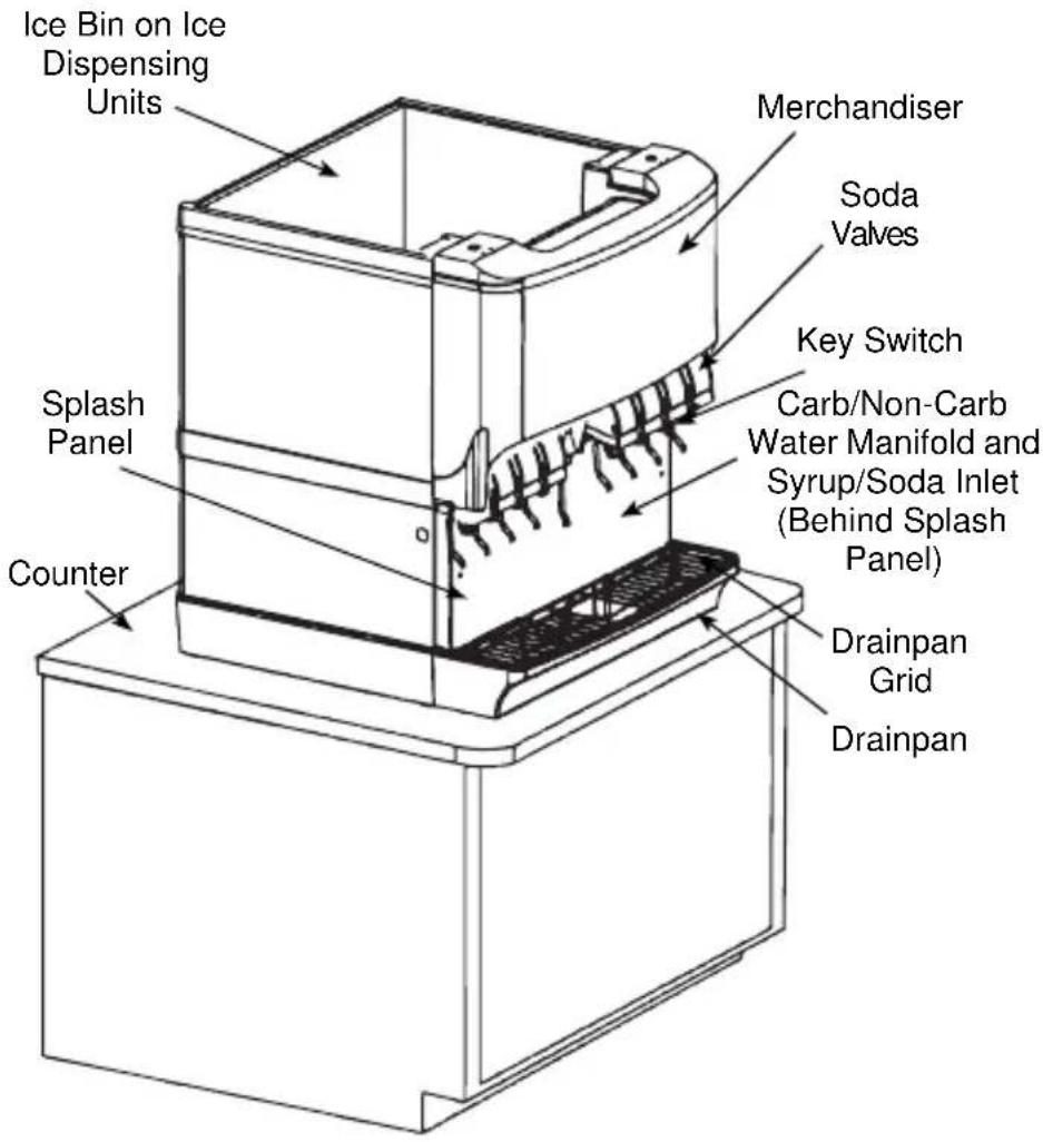
The plumbing diagram is printed on a white vinyl label, located above the inlet tubes for syrup and water. The plumbing diagram label can be accessed by removing the splash panel of the dispenser. The plumbing diagram label explains which inlet coldplate fittings supply which dispenser valves and water manifolds.
The water supply must first be connected to the carbonator pump (not shown) before plumbing to connection “A” shown on the plumbing diagram. The carbonator pump deck must be within six feet (1.8 m) of the dispenser for optimum performance. See the B-I-B installation diagram for system pressure settings.
Important
When installing cold carbonated (Internal Carb) equipment, never put a tee for the plain water connection in the line from the pump deck to the cold plate. Putting a tee in the line will create service problems and bad drink quality.
NOTE: Valves are read from right to left.
A check valve must be installed in the water supply line 3 feet (0.9 m) from the noncarbonated water connection “PW”. Contact factory if not installed.
Important
When installing a CEV unit the lowest recommended TDS reading for the water bath is 100 PPM.
Setting Pressures
PRE-MIX PRESSURES
Normal pre-mix pressure regulators must be set at 60 psi (4.14 bar). Diet pre-mix pressure regulators must be set at 40 psi (2.76 bar). If you are experiencing high foaming, decreasing the pressures may correct the problem. Spitting and popping usually requires slightly increasing the pressures. Pre-mix beverage valve pressures vary by type and manufacturer. Please consult the manufacturer of the valves you are using for specific instructions regarding operation of the valve.
COLD CARB AND AMBIENT SYSTEM PRESSURES
- Incoming tap water — must be at a minimum dynamic pressure of 40 psi (2.76 bar) and maximum static pressure of 65 psi (4.48 bar) (measured at inlet to pump).
Important
If incoming water pressure is under 40 psi (2.76 bar), a water booster is recommended. If incoming water pressure is over 65 psi (4.48 bar), a water regulating valve is required.
-
B-I-B pressure gauge must be set for a minimum of 60 psi (4.14 bar) or according to your line run.
-
Carbonator Pressure gauge (Use Preset Regulator):
- Cold Carbonation set for 75 psi (5.17 bar).
- Ambient systems must be set at 90 psi to 105 psi (6.20 bar to 7.24 bar).
Warning
Personal Injury Hazardous Moving Parts
Do not adjust regulator valve above 50 psig (3.45 bar).
Recommended operating parameters are 40 - 50 psig (2.76 - 3.45 bar).
NOTE: The Quickdraw unit requires a supply of CO2 . The pressure requirement for the CO2 supply is 75 psig (5.17 bar). The adjustable Ice Dispense CO2 regulator in the electric box must be set at 40 to 45 psi (2.76 to 3.10 bar). The Ice Dispense CO2 Regulator must never be set above 45 psi (3.10 bar).
Turn CO_2 supply on to the dispenser. Each cold carb pump deck is furnished with a fixed regulator set at 75 psi (5.17 bar). Ambient units need to be set between 90 and 105 psi (6.24 and 6.90 bar).
Important
The ice portion sizes must be adjusted to customer requirements at the time of installation. (See the Quickdraw Ice Portion Adjustments section for more information.)
BACK ROOM PACKAGE
Incoming tap water — Must be at a minimum dynamic pressure of 40 psi (2.76 bar) and maximum static pressure of 65 psi (4.48 bar). If pressure can not be attained, a water booster may be needed.
Carbonator Water pump motor — Powers the water pump. The water pump motor is part of the carbonator pump deck.
Carbonator Water pump — Pumps tap water into the carbonator tank. The water pump is part of the carbonator. The incoming water for the carbonator must be first run through the pump before connecting to the proper cold plate inlet.
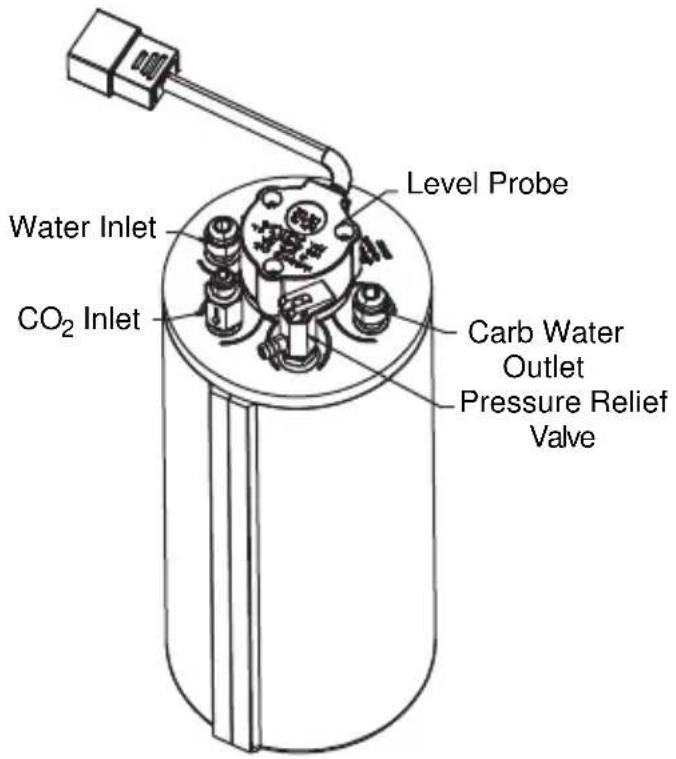
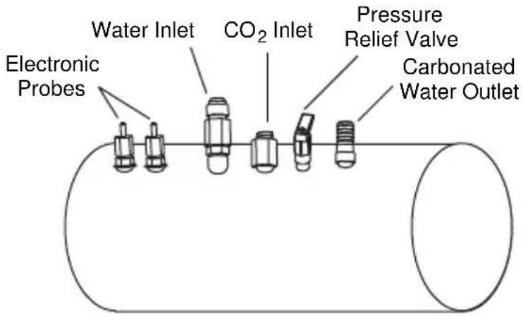
Internal/External Carbonator tank — Combines CO_2 gas and tap water to form carbonated water. The “carbonator” is the carbonator tank, water pump and water pump motor.
CO 2 cylinder — Holds highly pressurized carbon dioxide (CO 2 ). The CO 2 cylinder is a steel or aluminum cylinder tank. CO 2 gas flows through the primary pressure regulator.
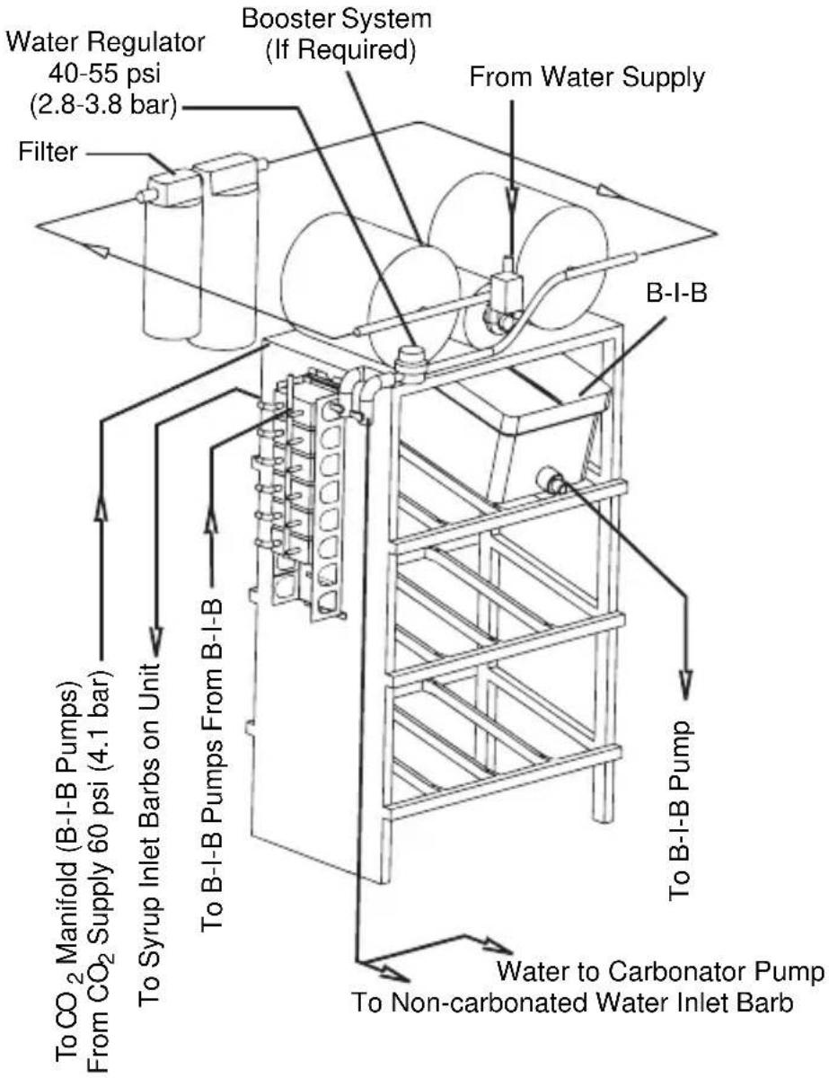
Bag-In-Box (B-I-B) pressure gauge — Set for 60 - 80 psi (4.14 - 5.51 bar). Indicates CO₂ pressure going to B-I-B pumps.
Primary pressure regulator – Lowers the CO_2 gas pressure, to 100 psi (6.90 bar), so the CO_2 gas will be at the proper pressure to enter the carbonator regulator.
Lowered outgoing pressure — Set for 75 psi (5.17 bar). Gauge indicates lowered outgoing pressure from the CO_2 cylinder after being routed through the primary pressure regulator at 90 psi to 105 psi (6.20 bar to 7.24 bar).
Secondary pressure regulator — Lowers the CO_2 gas pressure before the CO_2 gas flows to the syrup pump. CO_2 pressure activates the syrup pump. 30 psi (2.07 bar) on Flavor Magic and FRP-250 units with flavor shots.
Syrup pump — Draws syrup out of the bag-in-box syrup package. Syrup flows through the syrup lines to the dispenser for chilling, then dispensing. There is a syrup pump for each bag-in-box syrup system.
Bag-In-Box (B-I-B) syrup cartons — Box which contains a plastic bag, filled with syrup.
This Page Intentionally Left Blank
Typical Systems
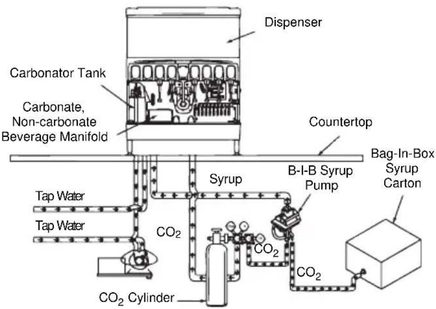
TYPICAL INTERNAL CARBONATION (IC)
ICE/BEVERAGE DISPENSING SYSTEM
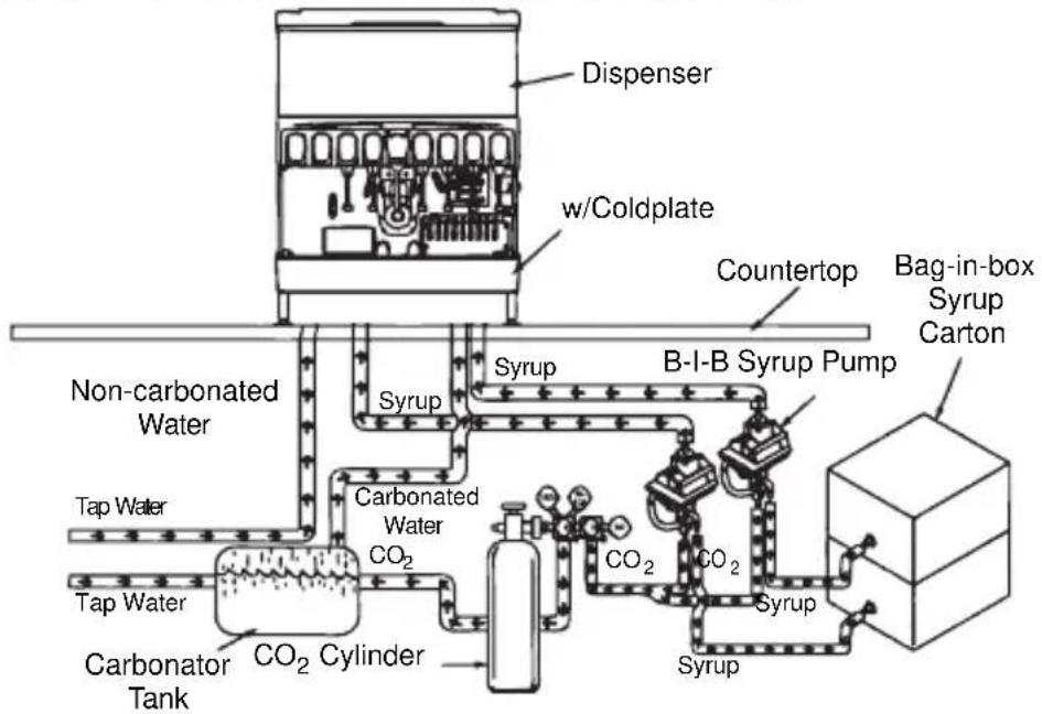
TYPICAL EXTERNAL CARBONATION (AMBIENT)
ICE/BEVERAGE DISPENSING SYSTEM
flowchart
graph TD
    A["Tap Water"] --> B["Non-carbonated Water"]
    B --> C["Carbonator Tank"]
    C --> D["Carbonated Water CO2"]
    D --> E["CO2 Cylinder"]
    E --> F["Syrup"]
    F --> G["B-I-B Syrup Pump"]
    G --> H["Syrup"]
    H --> I["Countertop"]
    I --> J["Dispenser"]
    K["bigging can be in"] --> L["Box with Bag-in-box Syrup Carton"]
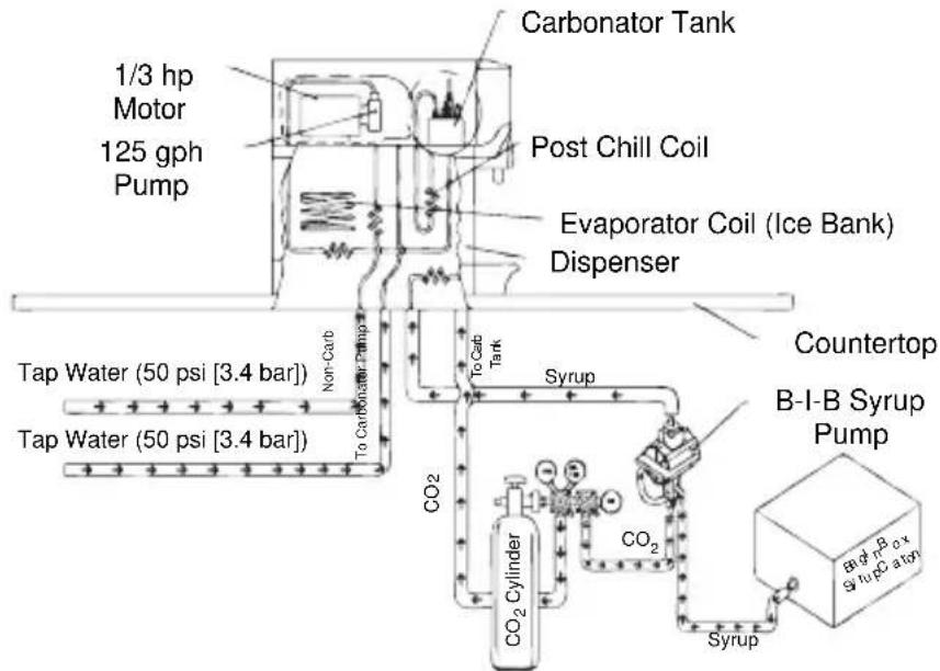
TYPICAL INTERNAL CARBONATION (IC) CEV DISPENSING SYSTEM
flowchart
graph TD
    A["1/3 hp Motor 125 gph Pump"] --> B["Carbonator Tank"]
    B --> C["Post Chill Coil"]
    C --> D["Evaporator Coil (Ice Bank) Dispenser"]
    D --> E["Tap Water (50 psi [3.4 bar"])]
    D --> F["Tap Water (50 psi [3.4 bar"])]
    D --> G["To Carbonator Pump"]
    G --> H["CO2 Cylinder"]
    H --> I["CO2"]
    I --> J["Syrup"]
    J --> K["B-I-B Syrup Pump"]
    K --> L["Countertop"]
    style A fill:#f9f,stroke:#333
    style B fill:#ccf,stroke:#333
    style C fill:#cfc,stroke:#333
    style D fill:#fcc,stroke:#333
    style E fill:#ffc,stroke:#333
    style F fill:#ffc,stroke:#333
    style G fill:#cfc,stroke:#333
    style H fill:#fcc,stroke:#333
    style I fill:#ffc,stroke:#333
    style J fill:#cfc,stroke:#333
    style K fill:#fcc,stroke:#333
    style L fill:#ffc,stroke:#333
NOTE: This is a simplified schematic to show the basic operation of the beverage system.
TYPICAL EXTERNAL CARBONATION (AMBIENT)
CEV DISPENSING SYSTEM
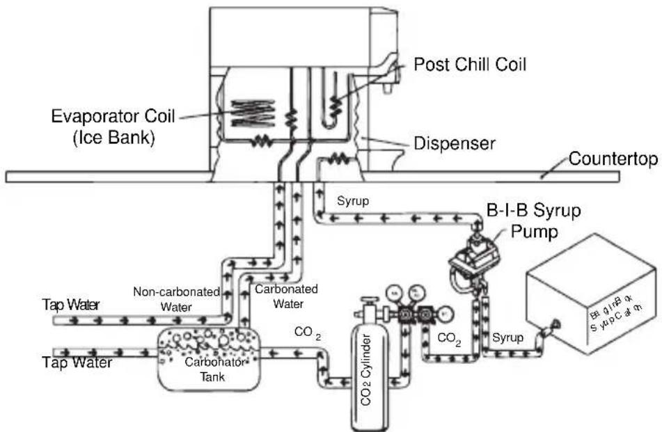
flowchart
graph TD
    A["Evaporator Coil (Ice Bank)"] --> B["Post Chill Coil"]
    B --> C["Dispenser"]
    C --> D["Countertop"]
    D --> E["Syrup"]
    E --> F["B-I-B Syrup Pump"]
    F --> G["CO2 Cylinder"]
    G --> H["Carbonated Water"]
    H --> I["Carbonator Tank"]
    I --> J["Tap Water"]
    J --> K["Non-carbonated Water"]
    K --> L["Tap Water"]
    L --> M["Carbonated Water"]
    M --> N["CO2 Cylinder"]
    N --> O["Syrup"]
    O --> P["B-I-B Syrup Pump"]
    P --> Q["Countertop"]
NOTE: This is a simplified schematic to show the basic operation of the beverage system.
CEV ELECTRONIC ICE & CARBONATION CONTROL
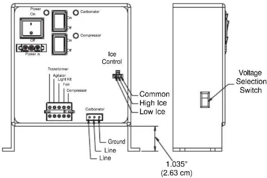
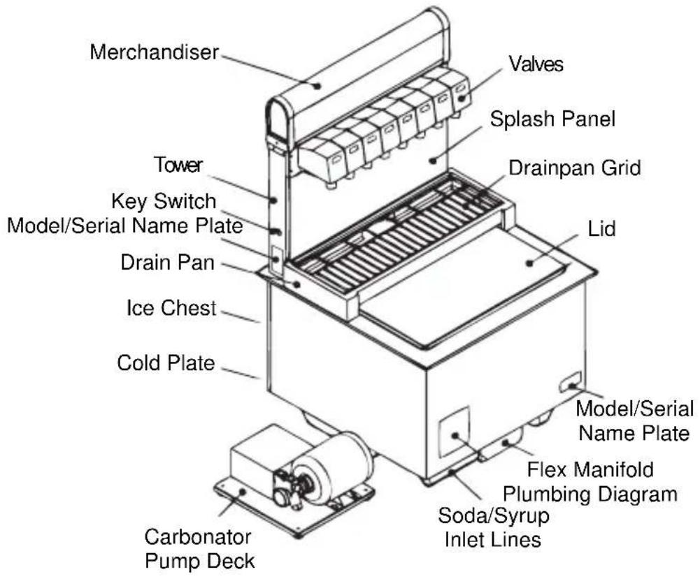
System Components
BLADE TOWER
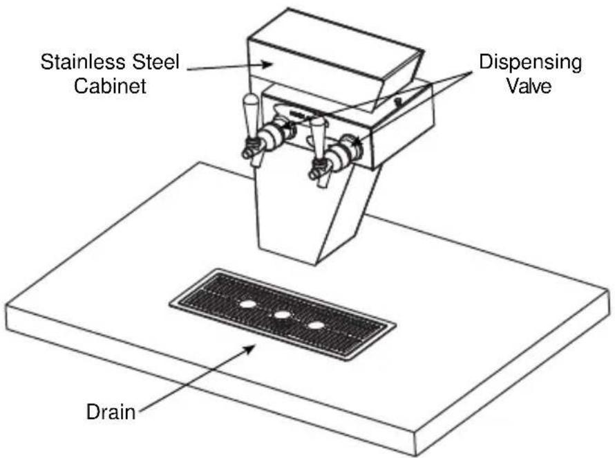
DROP-IN
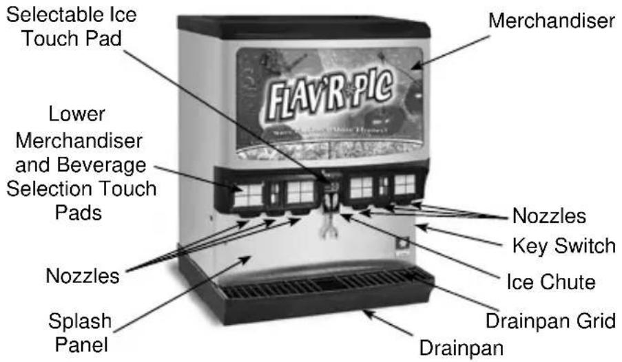
FLAVOR MAGIC MODULE
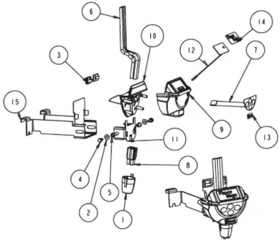
| Item Number | Part Number | Description |
| 1 501 | -25 NOZZLE | SOFTPOUR BLK |
| 2 008 | 50350 FLAT | WASHER 0.218ID X |
| 3 090 | 5403 CLIP PL | LAS WIRE & CORD |
| 4 501 | 2790 SCR 10 | -32X3/8 KNURL UNSLT |
| 5 502 | 9806 RIVNUT | 10-32 .020-.130 |
| 6 503 | 0446 TUBING | 1/4IN OD X 4FT |
| 7 503 | 1193 KEYPAD | 4 BUTTON 5 PIN FM |
| 8 503 | 1453 RETAINER | QUAD TUBE FM |
| 9 020 | 000473 CVR | FRONT FM ICEPIC |
| 10 020 | 000493 | CVR REAR FM ICEPIC |
| 11 | 020000846 | BRKT MNTG CENTER |
| 12 020 | 001033 | PAD LED FM |
| 13 020 | 001034 LAB | BEL LOGO SERVEND HORZ |
| 14 020 | 001035 | LABEL FM GRAPHIC |
| 15 | 20001153 | BRKT WELDED FM |
FLEXTOWER
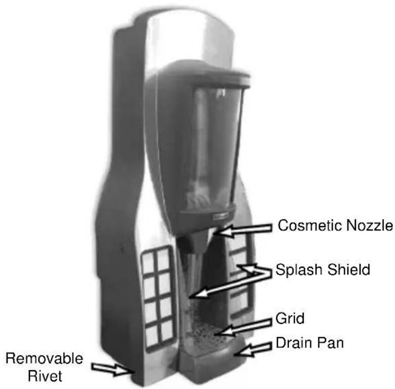
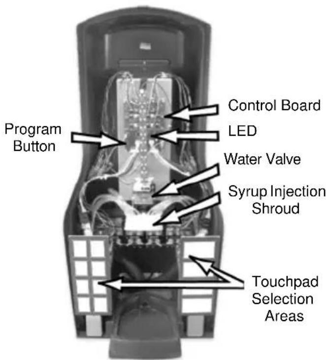
FLAV'R-PIC (FRP-250 & FRP-250SCI)
INTERNAL CARBONATORS
Vertical Carbonator
Horizontal Carbonator
BAG-IN-BOX (B-I-B) SYSTEM
Ice/Beverage and Counter Electric Dispensers
MDH-402 (CI & SCI) INTERNAL
CARBONATION DISPENSING SYSTEM
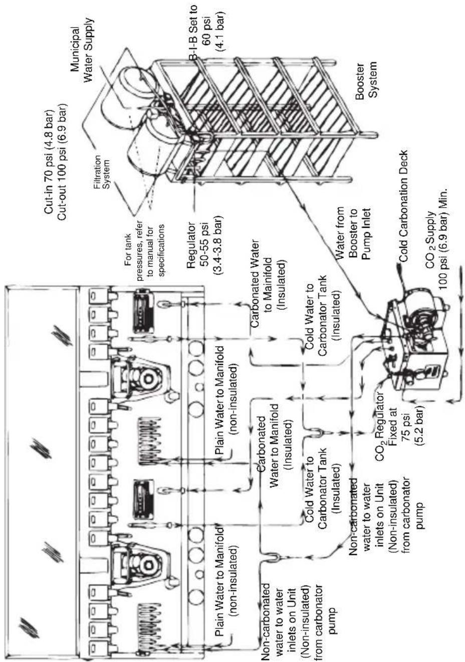
flowchart
graph TD
    A["Raw Material"] --> B["Plain Water to Manifold (non-insulated)"]
    A --> C["Non-carbonated water to water inlets on Unit (Non-insulated) from carbonator pump"]
    B --> D["Plain Water to Manifold (non-insulated)"]
    C --> E["Non-carbonated water to water inlets on Unit (Non-insulated) from carbonator pump"]
    D --> F["Carbonated Water to Manifold (Insulated)"]
    E --> G["Carbonated Water to Carbonator Tank (Insulated)"]
    F --> H["Carbonated Water to Mainifold (Insulated)"]
    G --> I["Carbonated Water to Mainifold (Insulated)"]
    H --> J["Water from Booster to Pump Inlet"]
    I --> K["Water from Booster to Pump Inlet"]
    J --> L["Cold Carbonation Deck"]
    K --> M["Cold Carbonation Deck"]
    L --> N["CO2 Supply 100 psi (6.9 bar) Min."]
    M --> N
    N --> O["CO2 Regulator Fixed at 75 psi (5.2 bar)"]
    O --> P["Regulator 50-55 psi (3.4-3.8 bar)"]
    P --> Q["For tank pressures, refer to manual for specifications"]
    Q --> R["Filtration System"]
    R --> S["Municipal Water Supply"]
    S --> T["Cut-in 70 psi (4.8 bar), Cut-out 100 psi (6.9 bar)"]
NOTE:
- Cold carbonator deck must be within 10 ft (3.05 m) of unit to function properly.
- Cold carbonation deck must be placed on a level surface.
- Cold carbonation deck requires booster system if supply water pressure is below 40 psi (2.8 bar), or if two units are installed on the same water line.
- filtration system may be placed before booster pump (per customer specifications).
- Items have been removed for clarity.
- 16 valve unit is shown.
Cleaning
ICE/BEVERAGE & COUNTER ELECTRIC DAILY CLEANING
All cleaning must meet your local health department regulations. The following cleaning instructions are provided as a guide.
Caution
Use only warm soapy water to clean the exterior of the tower. Do not use solvents or other cleaning agents. Do not pour hot coffee into the drain pan. Pouring hot coffee down the drain pan can eventually crack the drain pan, especially if the drain pan is cold or still contains ice.
Warning
Electric Shock Hazard
Unplug unit before servicing or cleaning.
Warning
When using cleaning fluids or chemicals, rubber gloves and eye protection must be worn.
Clean the exterior and drain pan:
- Turn off the key switch located on either right or left side of the unit.
- Lift the grid and remove it from the drain pan.
-
Using mild soap, warm water and a clean cloth, wipe the drain pan and splash panel. Then, rinse with clean, warm water. Allow plenty of warm (not hot) water to run down the drain of the drain pan, to remove syrup residue that can clog the drain opening.
-
Wash the grid, then rinse with clean water. Place the grid back in the drain pan.
-
Wash all exterior surfaces of the unit with warm water and a clean cloth. Wipe again with a clean, dry cloth.
Clean the dispensing valves:
- Remove nozzles and diffusers from beverage valves.
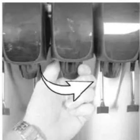
natural_image
Close-up of a hand holding three identical mechanical components, with a black arrow pointing to one component (no text or symbols visible)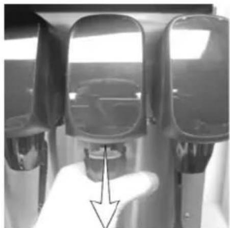
natural_image
Close-up of a hand pressing a button on a metallic device (no visible text or symbols)Nozzle Removal
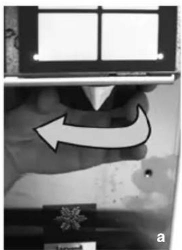
NOTE: The Flav'R-Pic (FRP-250 and FRP-250SCI) model have different dispensing nozzles. Remove nozzles from each dispense point by (a) grasping it firmly and turning it clockwise about 1/4" (0.64 cm) then (b) pulling down.
natural_image
Close-up of a hand holding a device with an arrow indicating rotation or movement (no visible text or symbols)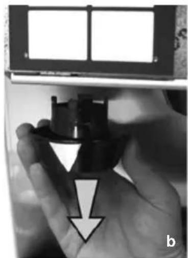
natural_image
Close-up of a hand holding a black plastic object with a downward arrow, no visible text or symbols-
Rinse nozzle and/or diffuser with warm, clean water.
-
Clean nozzles and diffusers with soapy water and a soft bristle brush.
- Clean the underside of the beverage valves with warm, soapy water. Rinse with clean damp towel.
- Replace nozzles and diffusers on valves.
- Turn on the key switch.
ICE/BEVERAGE AND COUNTER ELECTRIC MONTHLY CLEANING

Warning
Unplug unit before servicing or cleaning ice bin. Ice bin contains parts that can move at any time and will cause injury if hands are in the way.

Warning
When using cleaning fluids or chemicals, rubber gloves and eye protection must be worn.
Clean and sanitize the ice bin:
- Unplug unit and remove all ice from the ice bin.
- Mix a solution of mild detergent to clean the dispenser bin and components.
- Wash the ice bin using a sponge and the mild detergent solution.
- Using the mild detergent solution and a soft bristle brush or clean cloth, clean the following dispenser parts:
- Entire bin
- Paddle wheel (Ice Dispensing Units)
- Paddle wheel area (Ice Dispensing Units)
- Agitator (Ice Dispensing Units)
- Paddle wheel pin (Ice Dispensing Units)
- Ice chute (Ice Dispensing Units)
-
Rear bushing (Ice Dispensing Units)
-
Motor shaft (Ice Dispensing Units)
-
Strip lids (where applicable)
-
Rinse all the parts in clean, running water.
- Prepare 2 gallons (7.6 l) of sanitizing solution by mixing 1/2 ounce (14.2 g) of household bleach (that contains 5.25% sodium hypochlorite) with 2 gallons (7.6 l) of 120°F (48.9°C) water. The mixture must not exceed 100 PPM of chlorine. Or mix a solution of any approved sanitizer, following the directions for mixing and applying the sanitizer.
- Sanitize the ice bin and cold plate with the sanitizing solution for at least 10 seconds.
- Allow to air dry. Do not rinse.
Re-assembling the dispenser parts:
-
Re-assemble parts in the following order:
-
Bin liner (Ice Dispensing Units)
- Paddle wheel (Ice Dispensing Units)
- Agitator (Ice Dispensing Units)
- Paddle wheel pin (Ice Dispensing Units)
- Ice chute (Ice Dispensing Units)
-
Merchandiser
-
Hand tighten all knurled fasteners.
- Pour in fresh, sanitary ice and replace the plastic lid on the top of the dispenser.
- Plug in the unit's electrical cord.
- Check for proper ice dispensing.
CLEANING CHECKLIST
- C h e₂ supply. If CO₂ Supply is low, an arrow on the primary regulator gauge will point to a shaded area that reads “Low CO₂” or “Change CO₂ Cylinder.”
- Check syrup supply.
- Clean drain pan, grid, and splash panel.
- Clean the valve nozzles and diffusers.
CEV WATER BATH
It is recommended that the water bath be drained at least twice a year. Turn off the refrigeration.
Completely melt the ice bank. Refill the water bath with fresh water until water runs out the overflow tube. Turn on the refrigeration.
Disassembly
DISASSEMBLY FOR CLEANING AND MAINTENANCE (ICE/BEVERAGE DISPENSERS)
NOTE: Sanitize the ice dispenser at Initial Start-up in addition to monthly sanitizing. You will need a slotted screwdriver in order to disassemble.
Disassemble parts in the following order:
A. Merchandiser
B. Ice chute
C. Paddle wheel or agitator pins
D. Agitator
E. Paddle wheel
F. Bin liner
G. Paddle wheel area
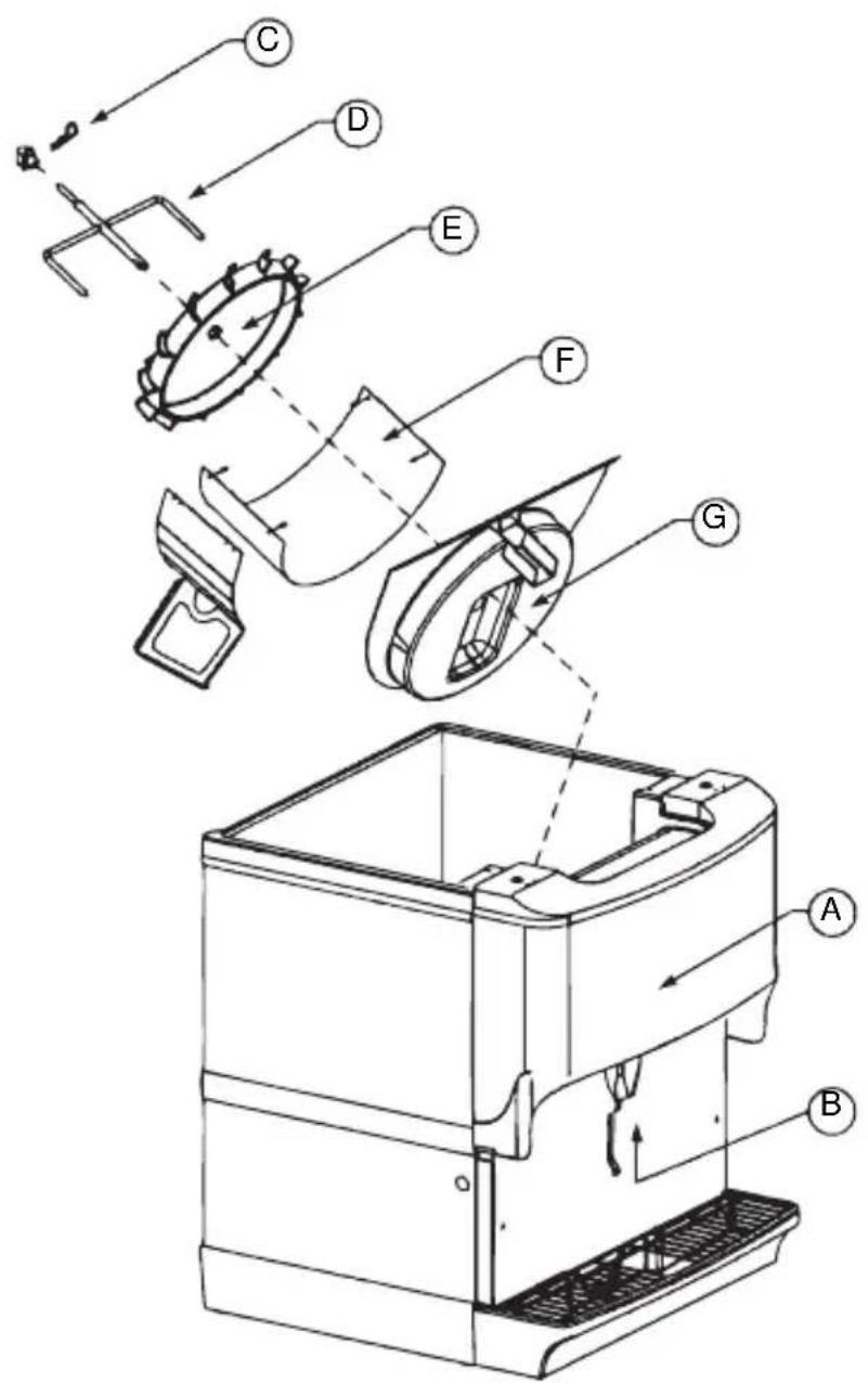
Beverage/Ice Dispenser
Accessing a Dispenser Bin Top Mounted with a Manitowoc Ice Machine:
- Remove the front panel of the ice machine.
- Remove the ice deflection baffle. This will give you access to the dispenser bin.
- If the Manitowoc ice machine is operating, wait for the sheet of ice to fall into the dispenser bin.
When the ice sheet falls into the dispenser bin, immediately place toggle switch of the ice machine to the OFF position. If the Manitowoc ice machine is NOT operating, place the toggle switch of the ice machine to the OFF position.
-
On models without a top mounted ice machine, remove the plastic lid from the top of the dispenser.
-
Remove all ice from the dispenser.
-
Disconnect electrical power to the dispenser.
-
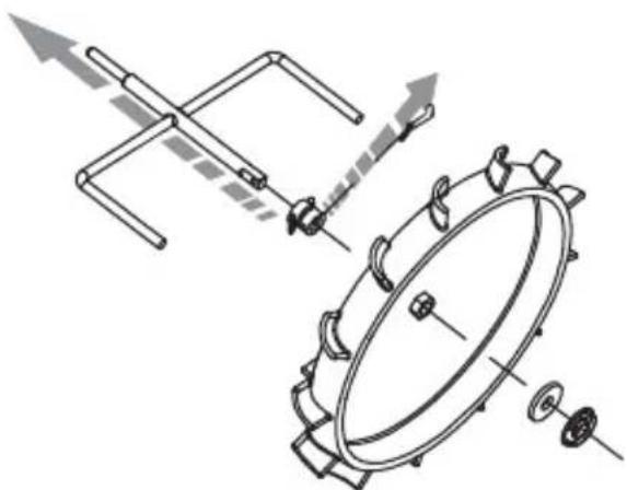
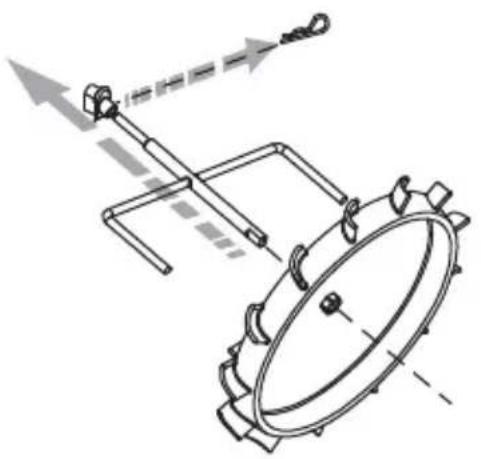
Remove agitator arm and paddlewheel pin.
Non-front Serviceable Motor
a. Rotate the agitator arm so the paddle wheel pin handle is pointing up, toward the ceiling.
b. Prepare agitator pin for removal by removing the stainless steel split ring.
c. Then remove the paddle wheel pin from the hole in the agitator.
d. Push the agitator bar toward the back of the unit until the agitator is free of the paddle wheel hub.
Front Serviceable Motor
a. With agitator arm in any position remove hitch clip pin from the mushroom bushing on the rear of the ice bin.
b. Push the agitator bar toward the bushing to remove it from the paddle wheel hub.
NOTE: If a top mount ice machine is installed, sliding the ice machine to one side will make bin component removal easier. If the ice machine is hard plumbed it will need to be disconnected.
natural_image
Technical line drawing of mechanical components with no visible text or symbolsNon-front Serviceable
natural_image
Technical line drawing of a mechanical assembly with no visible text or symbolsFront Serviceable
-
Remove paddle wheel, bin liner and paddle wheel area.
-
Move the front of the agitator to one side and slide the agitator forward until the rear of the agitator shaft is clear of the bushing.
-
Remove the agitator from the bin area.
-
Slide the paddle wheel from its shaft.
-
Loosen the four knurled fasteners that hold the bin liner in place.
-
Remove the bin liner.
-
Remove the paddle wheel area from the bin.
-
Discard the remaining ice in the bin.
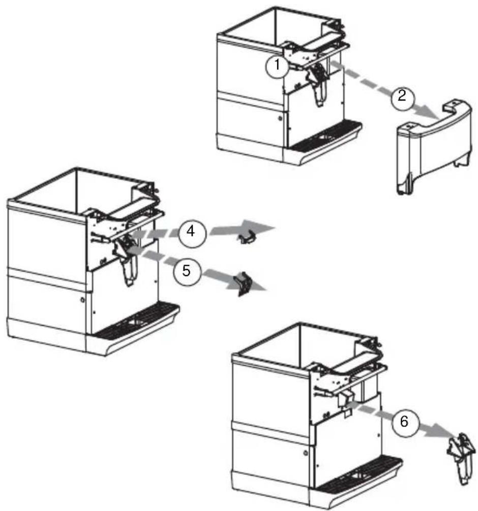
DISASSEMBLE THE ROCKING CHUTE
NOTE: For all Quickdraw units, refer to the Quickdraw Components section for ice chute information.
- Loosen the two knurled fasteners that hold the merchandiser in place.
- Remove the merchandiser.
- Remove outer bracket.
- Remove door lock.
- Remove door.
- Remove ice chute.
flowchart
graph TD
    A["1: Component 1"] --> B["2: Component 2"]
    B --> C["3: Component 3"]
    C --> D["4: Component 4"]
    D --> E["5: Component 5"]
    E --> F["6: Final Product"]
Ice Chute Removal
BLADE TOWER
How to Disassemble Tower Components
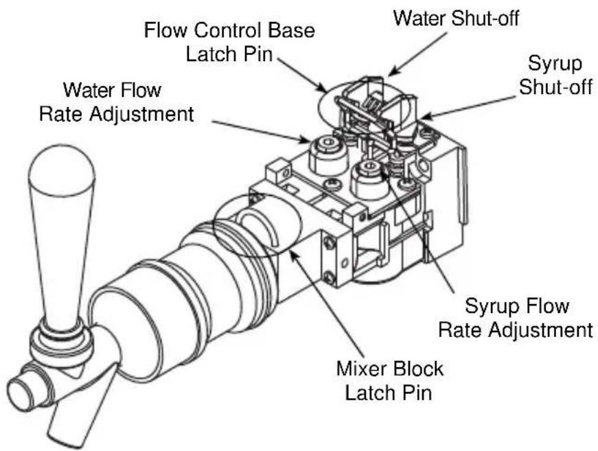
NOTE: This tower consists of two (2) valves combined as one (1) with a mixer block, mixer tube, and mixer. One pre-mix valve (CMBECKER) and one (1) Flomatic 424 flow control base.
Tower and Valve Disassembly:
- Remove tower housing cover by removing the thumb screw on the side.
- Turn OFF both shut-off valves on the flow control base and remove pressure by pulling the dispense handle to the ON position.
- Remove the latch pin on the mixer block by pulling straight up.
- Unscrew the inside flange nut on the pre-mix valve.
- Remove the pre-mix valve and mixer tube out the front of the tower.
- Remove the 424 flow control base by lifting up on its latch pin.
To reassemble follow these steps in reverse order.
Maintenance Schedule
| Every day | Dispensing Valves | For the pre-mix dispensing valve, run carbonated water ONLY through the valve and dispense nozzle for 10 seconds. Turn syrup shut OFF, and block the dispense nozzle base with a clean new napkin. Dispense carbonated water only for a few seconds to fully fill the dispense nozzle. Then unblock the dispense nozzle and flow carbonated water for 10 seconds. Wipe external nozzle surfaces with carbonated water, then turn syrup shut off, ON. Clean other nearby surfaces with carbonated water or cleaning solution. |
| Every day | Drip pan and drain hose | Wash with mild detergent. Rinse with clean water. |
| Every day | Quick disconnects | Wash with mild detergent. Rinse with potable water. |
| Weekly Outside, dispenser cabinet | Wash with clean water and mild detergent. Wipe dry. | |
| Every 3 months | Syrup circuits | Sanitize each syrup circuit. See “Cleaning and Sanitizing Procedure”. |
| Every 3 months | Water bath D | Drain, melt ice and clean using detergent and brush; rinse with potable water. Do not use water over 140°F (60°C). |
| Every 6 months | Condenser V | Vacuum fins or use soft bristle brush (scrub brush). |
| Every 6 months | Air purifier filter (if equipped) | Replace. |
Nightly Shutdown Procedure
It is recommended that the following steps are followed to keep your Blade Tower clean and running properly;
- Remove tower top piece to gain access to the valves.
- Turn the syrup shut off valve to the OFF position on all valves (2 valves per tower).
- Dispense carbonated water for 10 seconds from all valves.
- Leave valves off overnight and turn back on in the morning for use.
FLEXTOWER DAILY CLEANING
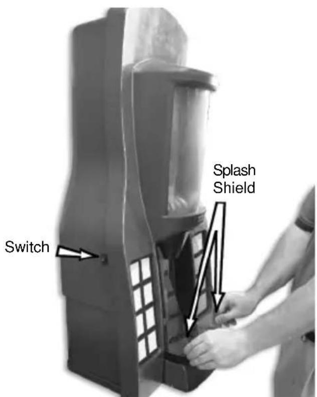
Cleaning the grid, splash shield and drain pan:
- Turn off the on/off rocker switch located on left side of the unit.
-
Lift the grid and splash shield to remove them from the drain pan.
-
Using mild soap, warm water and a clean cloth, wipe the drain pan. Then, rinse with clean, warm water. Allow plenty of warm (not hot) water to run down the drain of the drain pan, to remove syrup residue that can clog the drain opening.
-
Wash the grid and splash shield, then rinse with clean water. Place the grid and splash shield back in the drain pan.
-
Wash all exterior surfaces of the unit with warm water and a clean cloth. Wipe again with a clean, dry cloth.
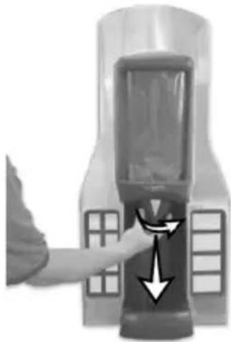
Cleaning the water valve nozzle and diffuser, cosmetic nozzle and syrup injection shroud assembly:
- Remove the cosmetic nozzle, and then remove nozzle-diffuser assembly from water valve.
natural_image
Close-up of a hand pressing down on a device with directional arrows indicating motion (no text or symbols visible)-
Rinse the cosmetic nozzle and water valve nozzle-diffuser assembly with warm, clean water.
-
Clean water valve nozzle-diffuser assembly with soapy water and a soft bristle brush.
-
Clean the cosmetic nozzle, underside of the water valve and the inside of the syrup injection shroud assembly with warm, soapy water. Rinse with clean warm towel.
-
Replace water valve nozzle-diffuser assembly and cosmetic nozzle.
-
Turn on the on/off rocker switch located on left side.
QUICKDRAW COMPONENTS
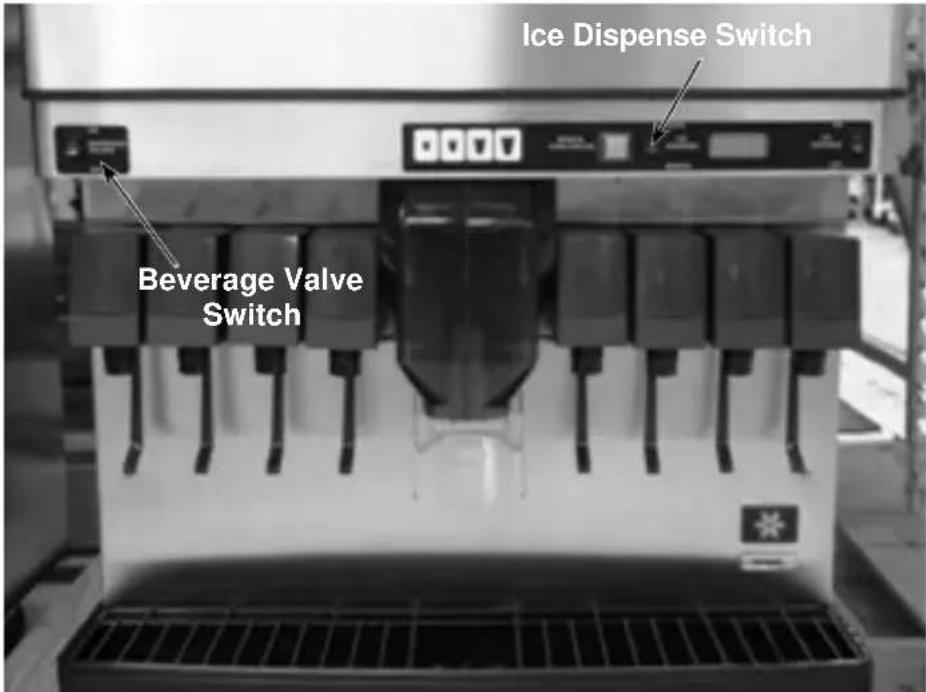
- Turn the beverage valve switch on the front left side to the off position.
-
Place a receptacle (bucket or large cup) under the ice dispense chute.
-
Place the ice dispense switch to MANUAL mode. The door will open and ice will fall into the bucket or cup.
-
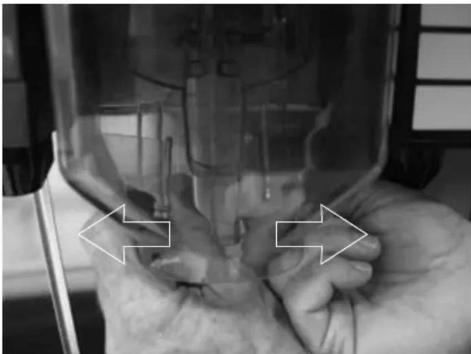
Remove the ice chute cover:
A. Grab the tabs on the back of chute and spread, pulling tabs off of pins.
natural_image
Close-up of hands operating a medical device with two white arrows pointing to the sides (no visible text or symbols)Part Number STH14 9/10 69
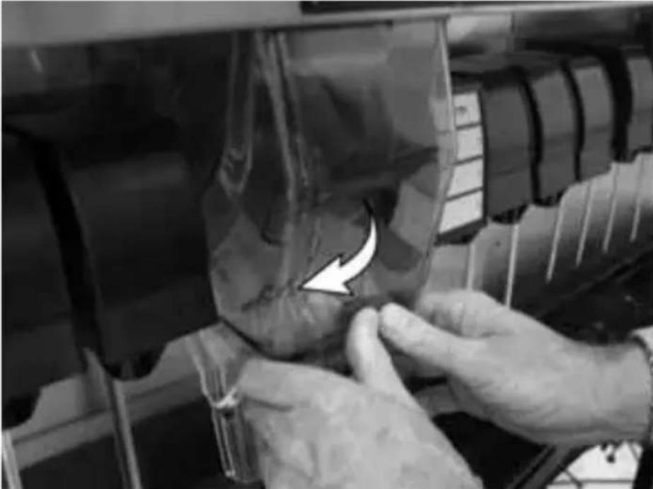
B. Push the bottom of chute to rear until it stops.
natural_image
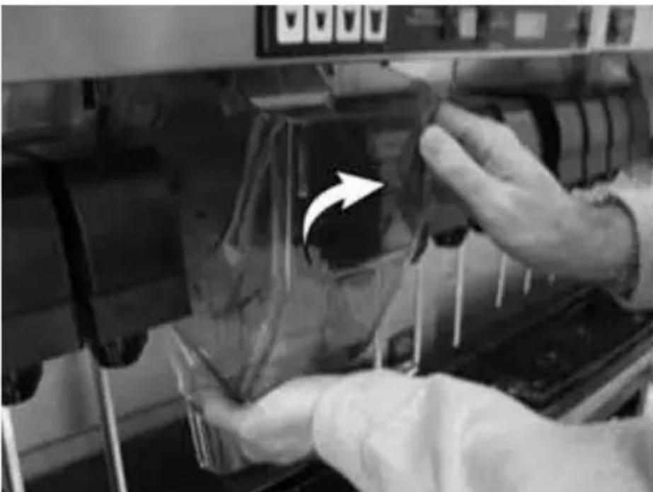
Close-up of hands adjusting a car interior panel with a white arrow pointing to a damaged component (no text or symbols visible)C. Rock top of the chute forward until top of chute clears unit.
natural_image
Close-up of hands operating a mechanical device with a white arrow pointing to a component (no visible text or symbols)- Remove ice wheel:
A. Pull cotter pin from the ice wheel axle.
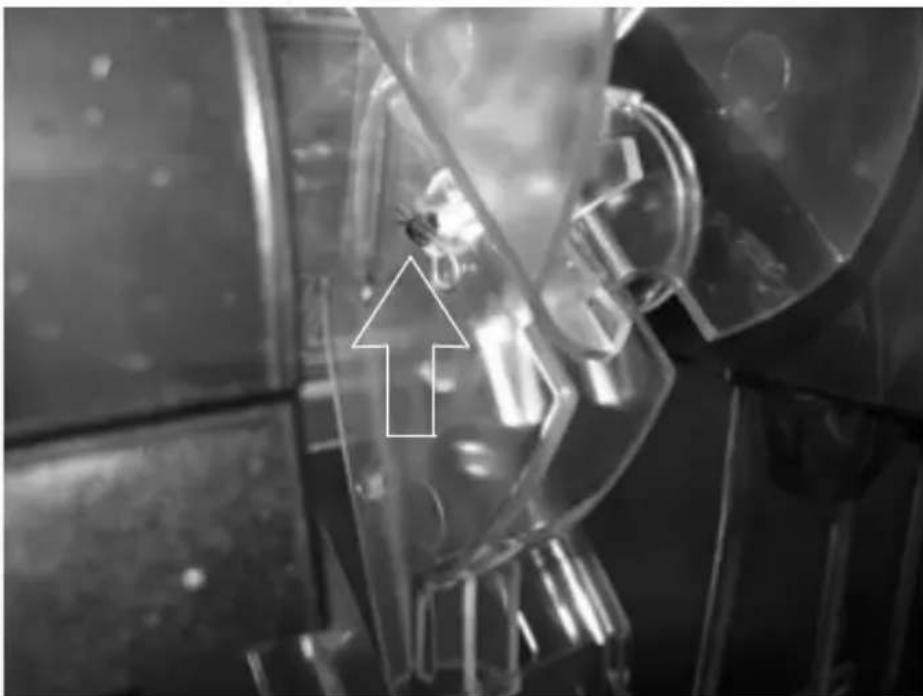
natural_image
Close-up of a mechanical component with a white arrow pointing upward, no visible text or symbolsB. Grasp handle of the pin on the right side, pulling until the ice wheel is loose.
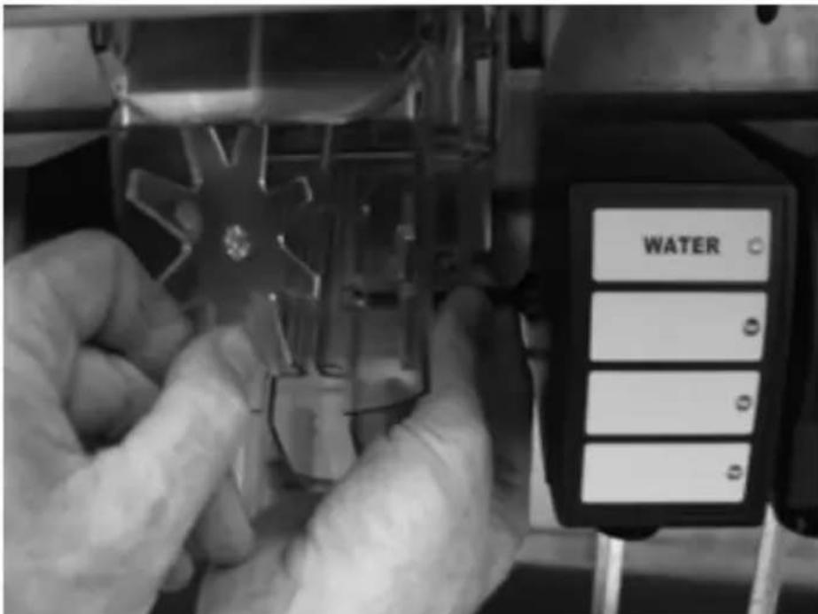
-
Mix a solution of mild detergent to clean the Quickdraw components. Using the detergent solution and a soft bristle brush or clean cloth, clean the following components:
-
Ice wheel
- Cup locator
- Quickdraw chamber
- D o o r
-
Ice chute cover
-
Rinse all parts in clean running water.
-
Mix a sanitizing solution of 1/4 ounce (7.4 ml) liquid, unscented bleach (5.25% CL NaO concentration) for each gallon of water. The mixture must provide 100 PPM available chlorine.
-
Using the sanitizing solution, a soft bristle brush, or a clean cloth, sanitize the components listed in Step 6. The ice chamber must be sanitized with a soft bristle brush to adequately clean the metering wheel slot and drainage area.
-
Reverse the procedure to reassemble the Quickdraw mechanism.
NOTE: When inserting the pin through the ice wheel, you will have to align the pin with the pattern of the wheel hole.
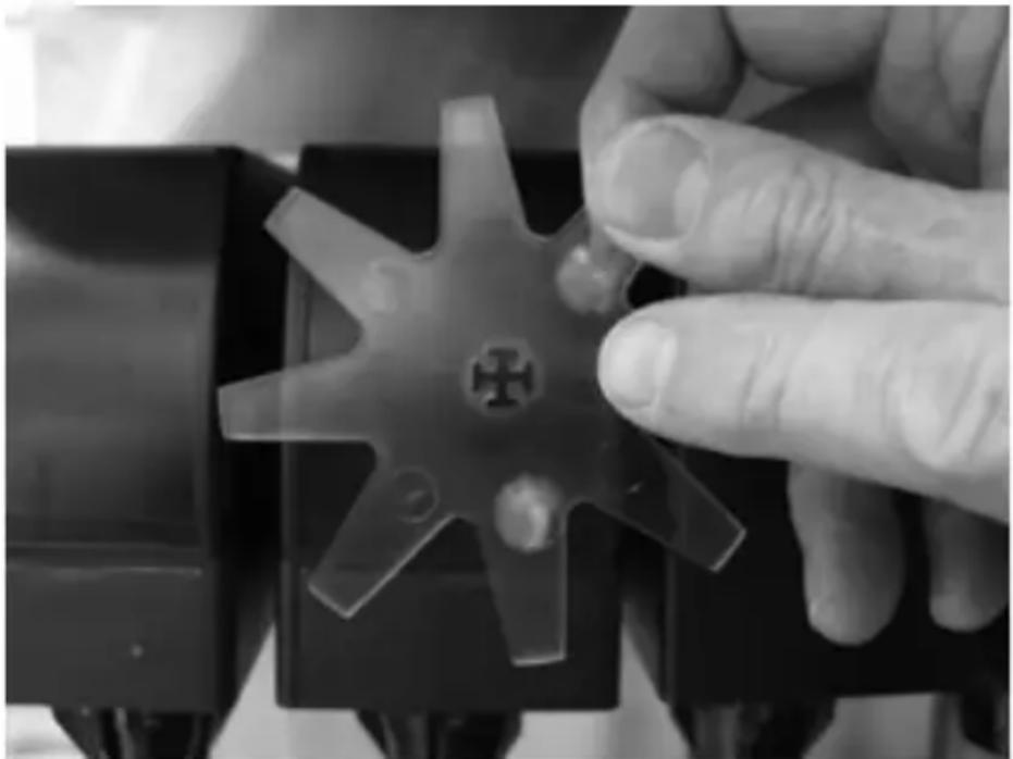
natural_image
Close-up of a hand adjusting a transparent mechanical component with six blades (no text or symbols visible)-
Place the ice dispense switch to the AUTO position, and place the beverage valve switch to the ON position.
-
Check for proper operation.
SELECTABLE ICE CRUSHER DISASSEMBLY
Before servicing or cleaning any part of the Selectable Ice unit be sure to unplug it from its power source. In order to access the module and crusher you must first remove the merchandiser by taking out the two screws located at the top of the merchandiser. Once the screws are removed, rotate the top of the merchandiser towards you and then lift the merchandiser up to remove from unit.
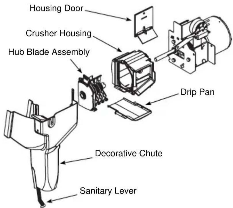
-
Unplug unit before cleaning or servicing the Crusher Assembly.
-
Remove the merchandiser by taking out the two screws located at the top of the merchandiser. Once the screws are removed rotate the top of the merchandiser towards you and then lift the merchandiser up to remove from unit.
NOTE: When the Merchandiser is removed an electrical safety switch disconnects power to the Ice Crusher assembly.
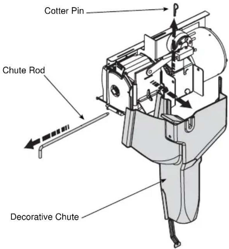
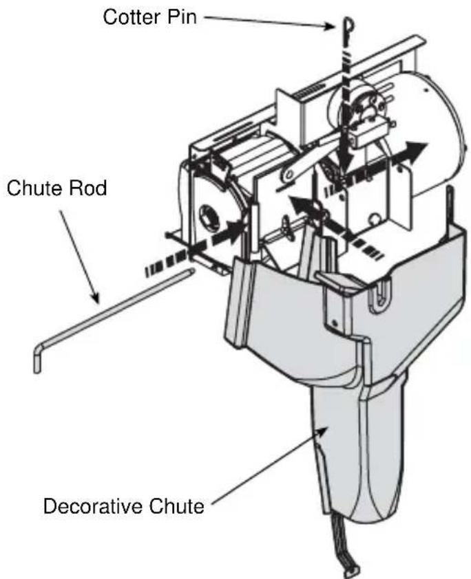
- Remove the ice chute by pulling the cotter pin out on the right side of the chute rod and pulling the chute rod toward the left side of the dispenser.
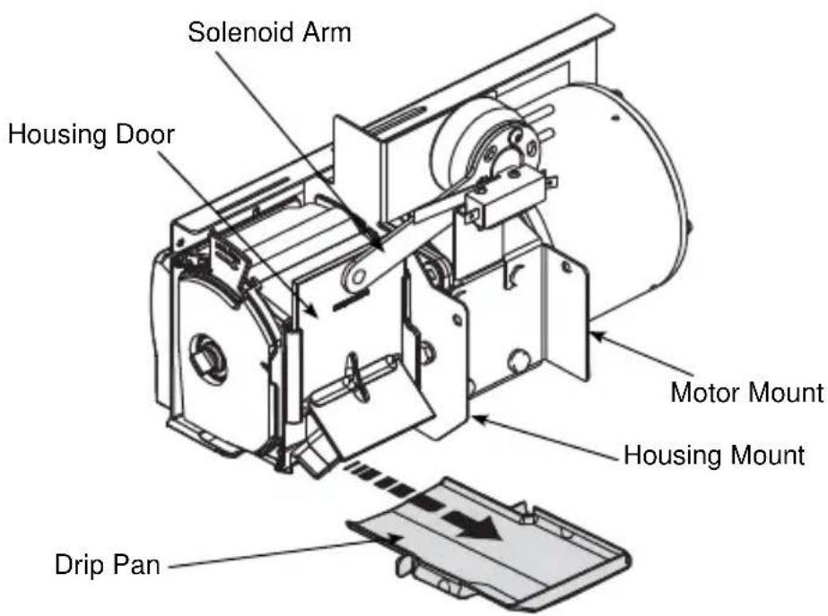
- Remove the crushed ice and cube ice doors from the dispenser by lifting the solenoid arms up and pushing the doors back to disengage the door from the solenoid arm.
74 Part Number STH14 9/10
-
Remove the crusher drip pan by pulling it forward.
-
Remove the ice crusher blade assembly from the crusher housing.
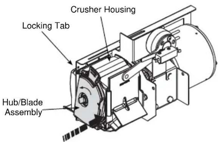
A. Unlock the crusher hub/blade assembly from the crusher housing by pushing locking tab in, and rotating the hub/blade assembly clockwise.
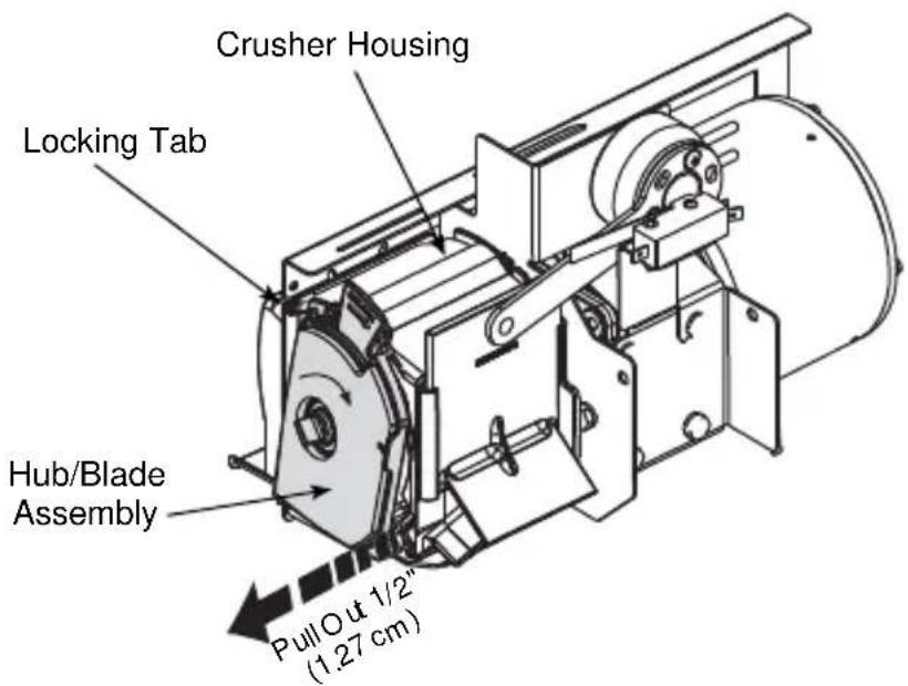
B. Pull the hub/blade assembly out of the housing approximately 1/2" (1.27 cm) to disengage the crusher axle from the motor shaft.
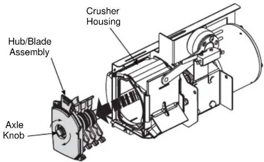
C. Rotate the knob on the crusher axle so it is in a vertical position. (This will ensure the rotating blades will not interfere with pulling the hub/blade assembly from the housing.)
D. Now the hub/blade assembly will be free from the housing and you will be able to completely remove the hub/blade assembly from unit.
REASSEMBLE THE ICE CRUSHER ASSEMBLY
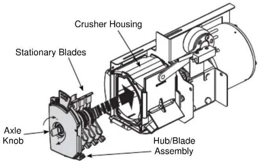
- Insert the hub/blade assembly into the ice crusher housing. When inserting the hub/blade assembly you must align the stationary blades with the locating slots in the ice crusher housing.
- When inserting the hub/blade assembly into the ice crusher housing you must also make sure the axle knob is in a vertical position. This will align the rotating blades with the housing to ensure a quick and easy installation.
-
Once all blades are in the crusher housing you will need to align the crusher axle with the motor shaft. You can do this by turning the axle knob and pushing the blade assembly toward the motor until the hub/blade assembly is flush with the end of the crusher housing.
-
To lock the hub/blade assembly into the housing, rotate the crusher hub/blade assembly counterclockwise until the locking tab snaps into place and the crusher hub/blade assembly is secure.
-
Replace the crusher drip pan.
-
Reattach the decorative ice chute by inserting the chute rod through the decorative chute, housing mount, and motor mount. Secure the chute rod by inserting the cotter pin through the rod on the right side of the chute.
-
Ensure the extension at the top of the decorative chute is behind the arm of the activation switch.
Replacement
NON-FRONT SERVICEABLE GEAR MOTOR REMOVAL
These instructions are provided as a guide for the removal of the gear motor. Depending on the model number of your dispenser, these instructions may vary slightly.
- Disconnect power from the electric receptacle.
- Remove all ice from the ice storage bin of the dispenser.
- Remove the paddle wheel pin from the paddle wheel/agitator assembly inside the dispenser bin.
- Remove the agitator assembly from the dispenser bin by pushing the agitator to the back of the bin. Angle the front of the agitator to the side. Pull the agitator forward then out of the dispenser.
- Remove the paddle wheel from the dispenser by pulling the hub of the paddle wheel to the back of the bin and off the gear motor shaft.
- Remove the splash panel from the dispenser and expose the gear motor.
- Disconnect the electric connector from the gear motor wire leads.
- Remove the pin in front of the gear motor.
- You must be able to remove the gear motor from the dispenser.
To install a replacement gear motor, reverse this procedure.
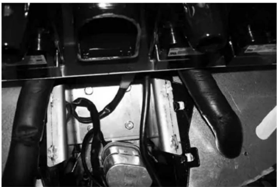
FRONT SERVICEABLE GEAR MOTOR REMOVAL
These instructions are provided as a guide for the removal of the gear motor. Depending on the model number of your dispenser, these instructions may vary slightly.
- Unplug the dispenser.
- Unplug the motor.
- Remove motor mount pins.
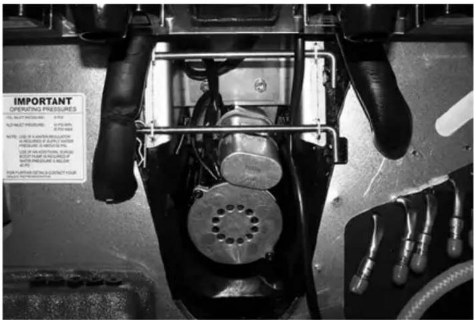
- Slide motor towards you.
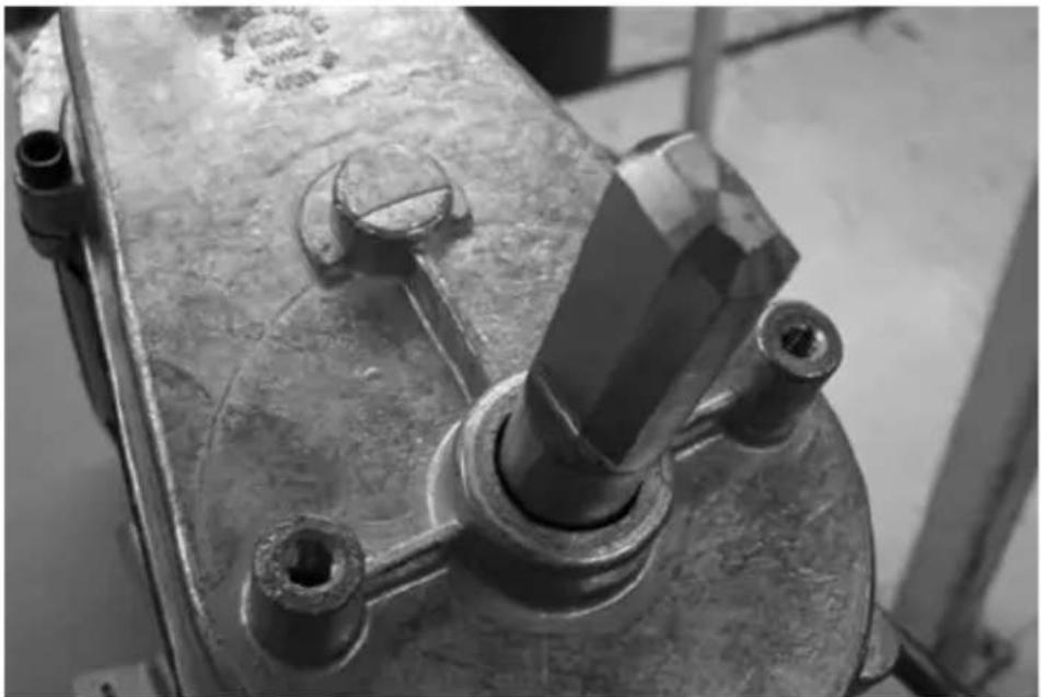
- Notice alignment of the chamfered edge of drive shaft.
natural_image
Close-up of industrial machinery components with visible wiring and mechanical parts (no text or symbols)-
New motor must have the same alignment (within 15 degrees).
-
To get correct alignment you can do one of two things:
a. Turn drive shaft with an adjustable wrench, being careful not to damage the drive shaft.
b. Plug in the unit, plug in the motor and use the ice dispense switch to move the drive shaft into correct alignment.
-
If you plugged in the unit to help with alignment of drive shaft now unplug the unit.
-
Slide motor up into housing, making sure that the tabs fit on the bracket.
natural_image
Close-up of a metallic mechanical component with bolts and a central shaft (no visible text or symbols)-
Install motor mount pins.
-
Plug in motor.
-
Test unit.
Sanitizing
BEVERAGE SYSTEM CLEANING

Warning
Flush sanitizing solution from syrup system.
Residual sanitizing solution left in system could create a health hazard.

Warning
When using cleaning fluids or chemicals, rubber gloves and eye protection must be worn.
Sanitize the beverage system at initial start-up as well as regularly scheduled cleaning. The drain pan must be in place under soda valves, to carry away detergent and sanitizing agents that will be flushed through valves.
BAG-IN-BOX SYSTEM SANITATION
The procedure below is for the sanitation of one syrup circuit at a time. Repeat to sanitize additional circuits.
You will need the following items to clean and sanitize the Bag-in-Box (B-I-B) beverage system:
- Three (3) clean buckets
- Plastic brush or soft cloth
- Mild detergent
- Unscented bleach (5% Na CL O) or Commercial sanitizer
-
Bag-In-Box bag connector
-
Prepare the following in the buckets:
-
Bucket 1 — warm to hot tap water for rinsing.
- Bucket 2 — mild detergent and warm to hot water.
- Bucket 3 — mix a solution of unscented bleach (5% Na CL O) or commercial sanitizer and warm to hot water. Mixture must supply 100 PPM available chlorine (1/4 oz. [7.1 g] bleach to 1 gallon [3.8 l] water).
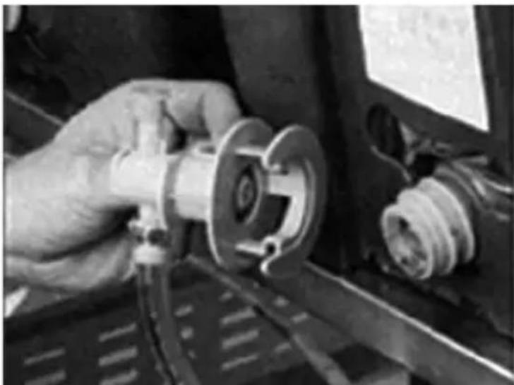
- Disconnect the "syrup-line side" of the bag-in-box connector.
natural_image
Close-up of a hand operating a mechanical component with a valve and coiled spring (no visible text or symbols)-
Rinse connector with warm tap water.
-
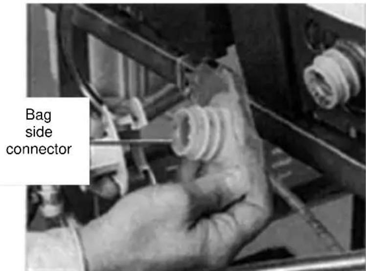
Connect syrup connector to B-I-B connector and immerse both into Bucket 1. A "bag-side" connector can be created by cutting the connector from an empty disposable syrup bag.
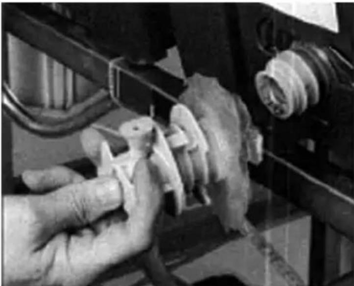
natural_image
Close-up of hands operating a mechanical component with no visible text or symbols-
Draw rinse water through system until clean water is dispensed. Most beverage valves allow the syrup side to be manually activated by depressing the syrup pallet.
-
Connect Bucket 2 to system.
-
Draw detergent solution through system until solution is dispensed.
-
Repeat steps 2-7 until all syrup circuits contain detergent solution.
-
Allow detergent solution to remain in the system for 5 minutes.
-
Connect Bucket 3 to system.
-
Draw sanitizing solution through system until solution is dispensed.
-
Repeat step 11 until all syrup circuits contain sanitizer solution.
-
Allow sanitizer solution to remain in system for 15 minutes.
-
Remove nozzles and diffusers from beverage valves.
-
Scrub nozzles, diffusers and all removable valve parts (except electrical parts) with a plastic brush or a soft cloth and the detergent solution.
-
Soak nozzles, diffusers and removable valve parts (except electrical parts) in sanitizer for 15 minutes.
-
Replace nozzles, diffusers and valve parts.
- Connect Bucket 1 to system.
- Draw rinse water through system until no presence of sanitizer is detected.
- Attach syrup connectors to B-I-Bs.
- Draw syrup through system until only syrup is dispensed.
- Discard first 2 drinks.
-
Prepare the following in three clean Figal tanks:
-
Rinse tank - fill with room temperature tap water.
- Detergent tank - mix approved beverage system cleaner with warm water as directed.
-
Sanitizing tank - mix a solution of unscented bleach (5% Na CL O) or commercial sanitizer and warm to hot water. Mixture must supply 100 PPM available chlorine (1/4 oz. [7.1 g] bleach to 1 gallon [3.8 l] water).
-
Disconnect all product and water lines from product tanks and remove carbonator.
- Locate the Figal syrup tank for the circuit to be sanitized. Remove both quick disconnects from the Figal syrup tank. Rinse quick disconnects in tap water.
- Connect rinse tank to the syrup line. Draw clean rinse water through the valve until syrup is flushed from the system.
- Connect detergent tank to the syrup line and draw detergent through the valve for two minutes. Then, allow remaining detergent to stay in the system for five minutes.
-
Connect rinse tank to the syrup line. Draw clean rinse water through the valve until detergent is flushed from the system.
-
Remove valve nozzle and diffuser as shown in Daily Cleaning instructions. Using a plastic brush or a soft cloth and warm water, scrub the nozzle, diffuser, bottom of the dispensing valve and cup lever, if applicable.
- Place removable valve parts (EXCEPT solenoids) in sanitizing solution for 15 minutes.
- Replace valve diffuser and nozzle on the beverage valve.
- Connect sanitizer tank to the syrup line and draw sanitizer through the valve for two minutes. Allow sanitizer to remain in the system for a minimum of 15 minutes.
- Reconnect syrup and carbonated water lines.
- Draw syrup through the lines to rinse the system. Discard drinks until at least two cups of satisfactory tasting beverage are dispensed through the valve.
Shipping, Storage and Relocation

Caution
Before shipping, storing, or relocating this unit, syrup systems must be sanitized. After sanitizing, all liquids (sanitizing solution and water) must be purged from the unit. A freezing environment causes residual sanitizing solution or water remaining inside the unit to freeze, resulting in damage to internal components.
This Page Intentionally Left Blank
Operation
Blade Tower Brixing
NOTE: Each tower consists of two valves combined as one with a mixer block, mixer tube and mixer. One Pre-ME valve (CMBEGKER) and one Flomatic 424 Flow Control Base
Set water flow rate first:
- Turn off syrup shut-off at post-mix (424) valve block.
- Use stop watch to time the dispense of soda water only.
- Dispense for 5 seconds.
- Record volume in a volume cup or ratio cup.
- Adjust the water flow rate as needed until 10 ounces (283.5 g) of water is measured in a 5 second (2 oz [56.7 g]/sec) dispense.
Set the syrup flow rate:
- Adjust the ratio (brix) of water to syrup (4.75:1) or 12.3 to 12.7 brix)
- Turn on syrup shut-off and turn off the water shut-off.
- Use a stop watch to time the dispense of syrup only.
- Dispense for 5 seconds.
- Record volume in a volume cup or ratio cup.
- Adjust syrup flow rate as needed until 2 ounces (56.7 g) of syrup is measured in a 5 second dispense.
- Use a refractometer if possible to get final brix ratio of 12.3 to 12.7. You will have to rely on volume adjustment above for diet products.
CEV Electronic Ice & Carbonation Control
| Element Function | |
Voltage Selection Switch(Red Side Switch)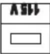 = 115 Volt Position = 115 Volt Position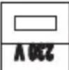 = 230 Volt Position = 230 Volt Position | ·Switch is used to select voltage,115 Volt or 230 Volt option.·When switch is in 115 Volt position the operating voltages are 100 Volts 50 Hertz and 120 Volts 60 Hertz.·When switch is in 230 Volt position the operating voltages are 220-240 Volts 50 Hertz and 208-230 Volts 60 Hertz. |
| On-Off Switch · Switch supplies power to all control functions.·When switch is in “on” position the agitation motor, transformer,merchandiser bulb and green power LED will be energized.(The green power LED will flash once per second for 5 seconds then stay on continuously.) | |
| Default Modes – LED/Default (RED)·RED Carbonator LED = Default·RED Compressor LED = Default | ·If the carbonator motor run time exceeds the preset fill times,which are (3) minutes or (7)minutes. The default mode will shut power off to carbonator pump motor for (15) minutes. It will then activate for one minute and if the motor does not shut down within the one-minute time frame the (15) minute off time and (1) minute on time default mode will repeat. The process will occur a total of (4) times and then the unit will shut down, requiring service or a manual reset.Disconnecting the power supply from unit or positioning carbonator switch to the “off” position and then returning switch to “on” position will reset control to normal operation (only applies to Internal Carb. units)·If the ice bank probe does not detect water in the CEV tub, the refrigeration will shut down and the compressor LED turns RED. |
| Carbonator Switch(Switch in OFF position for External Carb. and Juice units, which turns off green carbonator LED.) | Switch supplies power to the carbonator float switch and green Carbonator LED only. |
| Green Carbonator LED(Turned off on External Carb. and Juice Units) | The green carbonator LED illuminates when carbonator switch is in the ON position (only applies to Internal Carb. units).The green carbonator LED will flash rapidly when the carbonator motor is running. |
| Carbonator Fill Timing Jumper(Not used on External Carb. or Juice Units) | Carbonator tank fill timing provides pump failure protection in the event of water loss to carbonator pump (only applies to Internal Carb. units).A jumper clip within the control box sets the three optional time settings. Units are shipped with the jumper in (7) minute position (only applies to Internal Carb. units).J1 J1 J1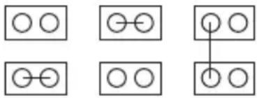 3 Minute 7 Minute UnlimitedNOTE: Time tolerance is ±20%.NOTE: See default mode functions 3 Minute 7 Minute UnlimitedNOTE: Time tolerance is ±20%.NOTE: See default mode functions |
| Green Compressor LED • I | Iuminates when the compressor switch is in the ON position.Flashes once per second when the compressor and condenser fan are energized. |
| Refrigeration Compressor Output | ·There are three wires from the ice bank probe to the control box. The white wire connects to the low ice bank probe pin (probe pin nearest evaporator coil). All three probe pins must be immersed in water to initiate the refrigeration cycle. The refrigeration system will operate until the low ice bank probe pin and center ice bank probe pin (black wire to the control box) is covered by ice. The third ice bank probe pin (probe pin farthest from evaporator coil) is the common or ground pin. The common or ground ice bank probe pin (green wire to the control box) should always be immersed in water and never in ice of ice bank.·Note: A delay circuit is built into compressor and fan motor circuit. Delay is (4) minutes ( ± 20% ) and will prevent compressor start-up if there is a power loss to the unit or the compressor switch is in OFF position and then placed in ON position. Delay will also apply if refrigeration cycle is stopped on full ice bank and ice bank probe sends a faulty signal to restart refrigeration system within the (4) minute delay time. |
Flavor Magic Programming
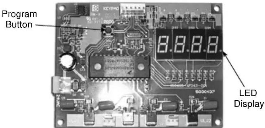
To exit the program mode at any time hold the program button for >3 seconds and the controller will switch to the dispense mode. The program mode can only be accessed by pressing the program button during the first five seconds of initial power up.
PROGRAM DISPENSE TIME
- The program mode is used to adjust the dispense time. To access the Program Mode, disconnect power to the control board, wait ten seconds and reconnect power.
- Press the program button one time on the control board during the first five seconds after power is applied.
- The LED display will show "P r o". To check the current dispense time, press the corresponding flavor button on the touchpad and the time will be displayed on the LED (Example "1.0"). a. To increase the time (+) by two-tenths second increments press flavor button 1 (far left button). b. To decrease the time (-) by two-tenths second increments press flavor button 3 (far right button). The default setting is one second.
PURGE/SANITIZE
Purge/Sanitize mode allows the user to purge air from the syrup lines during initial start-up. The second function of this mode is to energize the valves to move sanitizer through all syrup lines automatically.
Enter the Purge/Sanitize Mode by press the program button until "P – S" is displayed.
Pressing flavor button 1 (far left button) will activate a sequenced four second dispense that starts with flavor 1 then to flavor 2 etc. The valves will continue to cycle for 15 minutes or until the program button is pressed once.
DISPENSING MODES
Normal Dispense
With power applied to the control board, it will automatically start in dispense mode after a five second delay. The LED display will count down from four to zero and then show “- - - -” while in dispense mode. Simply pressing the desired flavor on the touchpad dispenses Flavor Magic.
Flavor Counter
The flavor counter tracks the number of flavor shots dispensed per flavor. To access Flavor Counter Mode, press the program button on the control board once for at least three seconds. The LED display will show "C n t". In the count mode the Flavor Magic module will not dispense. Check the number of dispenses for any flavor by pressing the corresponding touchpad button. To check another flavor press the program button once and then the corresponding flavor button on the touchpad. To return to dispense mode press the program button until the LED display shows "----".
CHANGING NUMBER OF ACTIVE FLAVORS
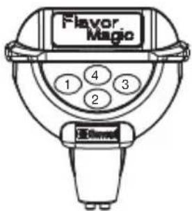
To line up flavors with valves, note that valve outlets number from left to right 1...2...3...4. Touch pad flavor tab is numbered as shown below. Connect vinyl tube from outlet 1 and dispense with flavor tab 1, etc.
The current Flavor Magic control board is set up in the 4 flavor default mode. This mode will handle all dispensing situations whether 3 or 4 flavors are used. Some early boards were set up as default in the 3 flavor mode. If the customer desires to add another flavor for a total of 4, proceed as follows:
-
Power down the circuit board by disconnecting the 24 volt connector in the lower left hand side of the board. "24VAC" is imprinted on the board next to the pin connection.
-
Wait a minimum of 10 seconds.
-
Power up the board by connecting the 24 volt connector.
-
IMMEDIATELY (within 5 seconds) press and hold the "PROG" button down.
-
After a few seconds, the number "4" will appear on the display.
-
Release the "PROG" button. The board will cycle the display from "Pro" to "4.....3.....2.....1.....0" and then to "----".
-
The circuit board is now enabled to dispense the 4th flavor. The 4th flavor button is the top middle button.
-
A flavor tab for the 4th flavor will have to be added to the touch pad. To do this, obtain one (1) P/N 5030780 20 flavor decal pad. Remove the P/N 5031579 decal overlay and add the 4th flavor tab as well as replace any flavor tabs which came off when removing the decal overlay. Note position of 4th flavor on the touch pad in the picture and placed tab where indicated. Obtain a new P/N 5031579 decal overlay and place over the tabs.
If the customer decides to go back to 3 flavors, it will not be necessary to change the board back to 3 flavors. However, it can be done by following steps 1 through 6 above. The number “3” will appear on the display. Then disconnect the number “4” syrup from the system, remove the 5031579 decal overlay, remove the flavor tab “4” and replace the 5031579 decal overlay. It would be a good idea to have an additional P/N 5030780 in case flavor tabs are damaged in the process.
The blue LED on the touch pad can be set to one of two display modes:
- Steady illumination. This is the default mode and the LED will remain on steady until dispense is activated. The light will flash only when product is being dispensed. In this mode, the control board display will read "Off".
- Flash mode. The LED will turn on for 1/2 second and off for 1/2 second.
Enter the Flash mode by pressing the program button until a flashing “- - - -” is displayed. Pressing flavor button 1 (far left button) will switch from “Off” (default) to “On”. The LED will now flash. To change back to the default simply press flavor button 1 again and the display should read “Off”. Press program button to exit to the next program function.
TIME DELAY AFTER DISPENSE
A time delay can be programmed into the control board which will prevent the system from dispensing another flavor for a period of from 0 to 10 seconds following a dispense. The default is 0 seconds.
Enter the Time Delay mode by pressing the program button until “d L A Y” is displayed. To check the current delay time press any flavor button one time and the current value will be displayed. To increase the time (+) by 1.0 second increments press flavor button 1 (far left button). To decrease the time (-) by 1.0 second increments press flavor button 3 (far right button).
Flav'R-Pic External Programming HOW TO CHECK FRP BRIX EXTERNALLY
If your FRP-250 has a control board with the external brix check ability you will be able to put the unit into brix mode by doing the following:
- Turn the keyswitch to the "OFF" position.
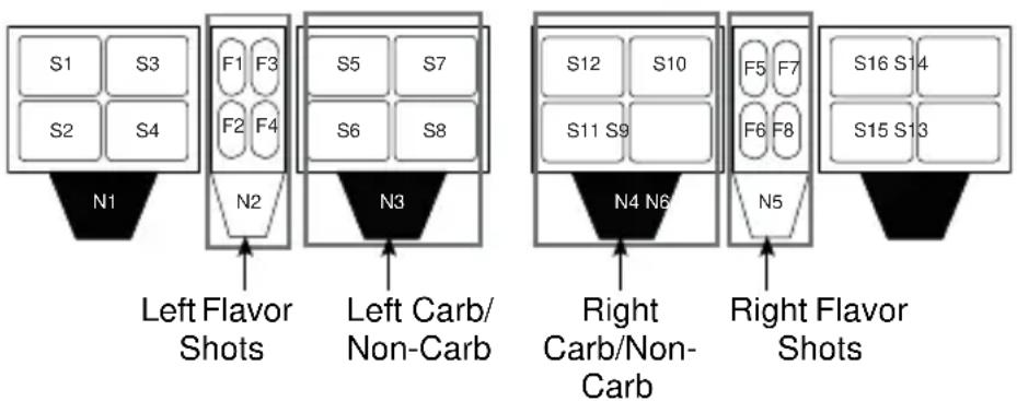
- With the keyswitch still in the "OFF" position, press and hold the F1 touch pad button for the left side or F5 for the right while turning the keyswitch back to the "ON" position.
- F1 = Left Side Brix Check
- F5 = Right Side Brix Check
flowchart
graph TD
    A1["S1 S3"] --> B1["N1"]
    A2["S2 S4"] --> B2["N2"]
    B1 --> C1["Left Flavor Shots"]
    B2 --> C2["Left Carb/Non-Carb"]
    C1 --> D1["S5 S7"]
    C2 --> D2["S6 S8"]
    D1 --> E1["S12 S10"]
    D2 --> E2["S11 S9"]
    E1 --> F1["F5 F7"]
    E2 --> F2["F6 F8"]
    F1 --> G1["S16 S14"]
    F2 --> G2["S15 S13"]
    G1 --> H1["N4 N6"]
    G2 --> H2["N5"]
    style A1 fill:#f9f,stroke:#333
    style A2 fill:#f9f,stroke:#333
    style B1 fill:#ccf,stroke:#333
    style C1 fill:#cfc,stroke:#333
    style D1 fill:#fcc,stroke:#333
    style E1 fill:#cff,stroke:#333
    style F1 fill:#ffc,stroke:#333
    style G1 fill:#cfc,stroke:#333
    style H1 fill:#fcc,stroke:#333
    style I1 fill:#ffc,stroke:#333
    style J1 fill:#cfc,stroke:#333
    style K1 fill:#fcc,stroke:#333
    style L1 fill:#cfc,stroke:#333
    style M1 fill:#fcc,stroke:#333
FRP-250 with Flavor Shots
flowchart
graph TD
    subgraph_Left_Hidden_Touchpad_Button["Left Hidden Touchpad Button"]
        S1["S1"] --> N1["N1"]
        S3["S3"] --> N1
        S2["S2"] --> N1
        S4["S4"] --> N1
        F1["F1"] --> N3["N3"]
        F3["F3"] --> N3
        F2["F2"] --> N3
        F4["F4"] --> N3
    end
    subgraph_Right_Hidden_Touchpad_Button["Right Hidden Touchpad Button"]
        S5["S5"] --> N4["N4"]
        S7["S7"] --> N4
        S6["S6"] --> N4
        S8["S8"] --> N4
        F5["F5"] --> N6["N6"]
        F7["F7"] --> N6
        F6["F6"] --> N6
        F8["F8"] --> N6
    end
FRP-250 with out Flavor Shots
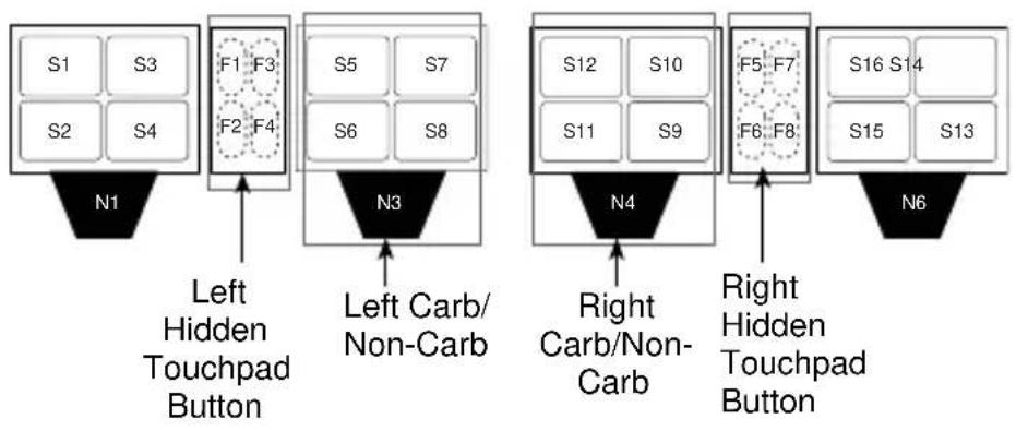
NOTE: The buttons for FRP units without flavor shots are located in the same area, but are hidden.
- You can now stop pressing on the F1 or F5 button and the 4 LEDs around the touch pad area should now be illuminated. If not illuminated you did not successfully go into external brix mode and need to try again, or the FRP unit is not equipped with this program mode.
In this setting when a corresponding touch pad is pressed water or syrup will be dispensed for a fixed duration in order to check your ratios using a standard brix cup.
-
In this mode you can now check the brix for any water or syrup valve that corresponds to the board. Use the illustration in Installation/Brixing or the Control board, Valve, Touch Pad Matrix to identify the valves and which board they correspond to. Brixing information can also be found on the unit, on the right hand side of the control board cover label. By using this label in combination with the plumbing label located on the foam front you will be able to identify each valve, water, and/or syrup combination.
-
When finished checking the brix return the unit to dispense mode by turning the keyswitch to the "OFF" position, waiting till the touch pad LEDs are not illuminated, then turn the keyswitch back to the "ON" position.
Important
If left in external brix mode for longer than 5 minutes it will automatically time out and return to dispense mode.
If brix adjustments are needed you will have to remove the merchandiser to make the mechanical adjustments. Please see PROGRAM MODE 2 in this section for internal brixing instructions using the control board and the Brixing Procedure for detailed instructions on brixing the FRP-250.
CRUSHED OR CUBED DEFAULT
This selectable ice option will allow the unit to always default to either cube or crushed ice or remain at the last selection. This only applies to control boards 020000875 Rev 7 and up.
How to set default ice dispense setting
CUBE DEFAULT
- Power on the unit by plugging in receptacle and holding the cube button at the same time, cube will flash 2 times. Unit will now change to cube 10 seconds after crush is selected.
CRUSH DEFAULT
- Power on the unit by plugging in receptacle and holding the crushed button at the same time, crush will flash 2 times. Unit will now change to crush 10 seconds after cube is selected.
LAST SELECTION DEFAULT
- Power on the unit by plugging in receptacle and holding cube and crush at the same time, cube and crush will flash 2 times. Unit will now remain in selection of last request.
NOTE: If power is lost to the unit and then powered up again the unit will retain the last setting and not return to factory settings.
Flav'R-Pic (FRP-250) Programming
PROGRAM MODE 1
Carb/Non-Carb & Flavor Shot Duration Settings
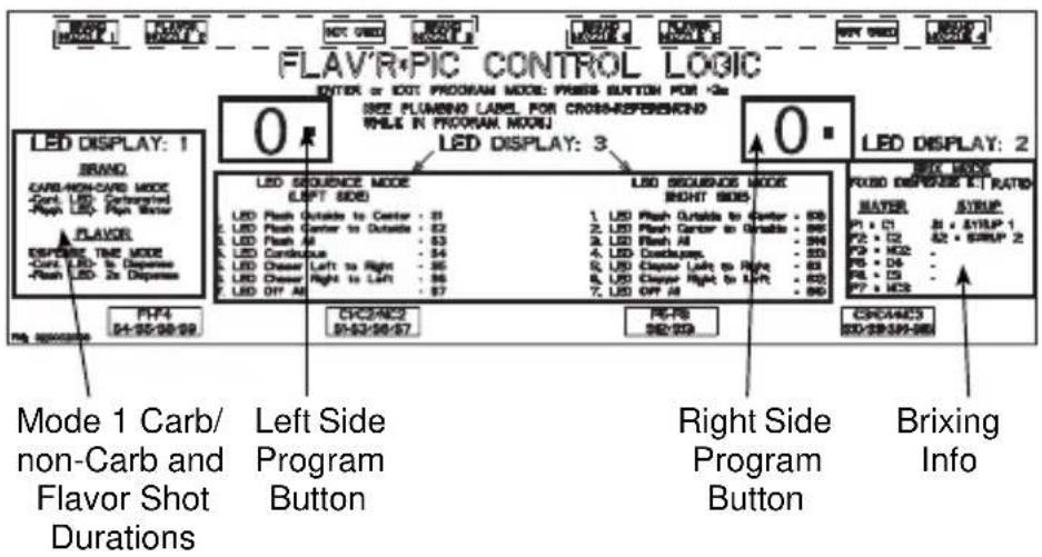
Mode 1 displayed above, allows you to select your carb/non-carb settings for dispense points N3 (Nozzle 3) through the left control board and/or N4 (Nozzle 4) with the right control board. Only nozzles N3 and N4 have the option to be a non-carb drink, N1 and N6 are carbonated only. Mode 1 is also used to set a 1 or 2 second dispense duration for flavor shots on N2 and N5 using their corresponding control board.
N3 & N4 Carbonated or Non-Carbonated Drinks
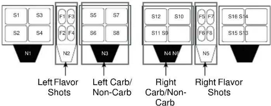
flowchart
graph TD
    A["Left Flavor Shots"] --> B["N1"]
    B --> C["S1 S3"]
    B --> D["S2 S4"]
    B --> E["F1 F3"]
    B --> F["F2 F4"]
    B --> G["N2"]
    G --> H["N3"]
    H --> I["S5 S7"]
    H --> J["S6 S8"]
    H --> K["N3"]
    K --> L["N4 N6"]
    L --> M["S12 S10"]
    L --> N["S11 S9"]
    L --> O["N5"]
    O --> P["S16 S14"]
    O --> Q["S15 S13"]
    L --> R["Right Carb/Non-Carb"]
    R --> S["N4 N6"]
    S --> T["Right Flavor Shots"]
FRP-250 with Flavor Shots
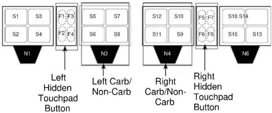
flowchart
graph TD
    subgraph_Left_Hidden_Touchpad_Button["Left Hidden Touchpad Button"]
        S1["S1"] --> N1["N1"]
        S3["S3"] --> N1
        S2["S2"] --> N1
        S4["S4"] --> N1
        F1["F1"] --> N3["N3"]
        F3["F3"] --> N3
        F4["F4"] --> N3
        S5["S5"] --> N3
        S7["S7"] --> N3
        S6["S6"] --> N3
        S8["S8"] --> N3
    end
    subgraph_Right_Hidden_Touchpad_Button["Right Hidden Touchpad Button"]
        S12["S12"] --> N4["N4"]
        S10["S10"] --> N4
        S11["S11"] --> N4
        S9["S9"] --> N4
        F5["F5"] --> N4
        F7["F7"] --> N4
        F6["F6"] --> N4
        F8["F8"] --> N4
        S16["S16"] --> N6["N6"]
        S14["S14"] --> N6
        S15["S15"] --> N6
        S13["S13"] --> N6
    end
FRP-250 with out Flavor Shots
- Choose a control board. If programming N3 (Nozzle 3) use the left control board, if programming N4 use the right control board. Beverage dispense points are designated by a black nozzle.
- Press the program button and hold for 3 seconds or until the LED displays 1.
- To set a carbonated drink for N3 (Nozzle 3) touch one of the following touch pads; S5, S6, S7, or S8 until the LEDs around the touch pad are constant.
- To set a non-carbonated drink for N3 (Nozzle 3) touch one of the following touch pads; S5, S6, S7, or S8 until the LEDs around the touch pad are blinking.
- Constant LEDs = Carbonated
- Blinking LEDs = Non-Carbonated
-
Follow the same instructions for N4 (Nozzle 4) using the right control board and touch pads S9, S10, S11, or S12.
-
When you are finished, press the program button to go to a different mode or save your settings and return the control board to the dispense mode by pressing the program button and holding for 3 seconds or until the LED displays 0.
Flavor Shot Dispense Duration
-
Choose a control board. If programing flavor shots for N2 (Nozzle 2) use the left control board, if programming shots for N5 use the right control board. Flavor shot dispense points are designated by a blue nozzle.
-
Press the program button and hold for 3 seconds or until the LED displays 1.
-
To set a 1 second shot for N2 (Nozzle 2) touch one of the following touch pads; F1, F2, F3, or F4 until the LEDs around the touch pad are constant.
-
To set a 2 second shot for N2 (Nozzle 2) touch one of the following touch pads; F1, F2, F3, or F4 until the LEDs around the touch pad are blinking.
- Constant LEDs = 1 second shot
- Blinking LEDs = 2 second shot
-
Follow the same instructions for N5 (Nozzle 5) using the right control board and touch pads F5, F6, F7, or F8.
-
When you are finished, press the program button to go to a different mode or save your settings and return the control board to the dispense mode by pressing the program button and holding for 3 seconds or until the LED displays 0.
PROGRAM MODE 2
Brixing
Mode 2 displayed above, puts your Flav'R-Pic into brix mode. In this setting when a corresponding touch pad is pressed, water or syrup will be dispensed for a fixed duration in order to set your ratios using a standard brix cup and making adjustments to the mechanical valves. Follow the steps below to put a board into brix mode.
- Choose a control board. If brixing drinks for N1 (Nozzle 1) or N3 use the left control board, if brixing drinks for N3 or N6 use the right control board. Beverage dispense points are designated by a black nozzle.
- Press the program button and hold for 3 seconds or until the LED displays 1. Press the program button again until 2 is displayed on the control board LED display.
NOTE: Programming one board at a time will make it easier for you to identify the corresponding valves and dispense points.
-
With the a board in Mode 2, you can now brix any water or syrup valve that corresponds to the board. Use the illustration in Installation/Brixing or the Control board, Valve, Touch Pad Matrix to identify the valves and which board they correspond to. Brixing information can also be found on the unit, on the right hand side of the control board cover label. By using this label in combination with the plumbing label located on the foam front you will be able to identify each valve, water, and/or syrup combination.
-
Replace the nozzle when done then move on to another nozzle or, if you are finished brixing, return the control board to the dispense mode by pressing the program button and holding for 3 seconds or until the LED displays 0.
A brixing break down for each nozzle is available in the Brixing Procedure section of this manual.
PROGRAM MODE 3
Light Sequences
Mode 3 displayed above, allows you to set the light sequence for the touch pad LEDs. Follow the steps below to place the board into this mode and set sequences.
- Choose a control board. If setting the light sequence for the touch pad area on the left use the left control board, or if you are setting them for the right, use the right control board.
- Press the program button and hold for 3 seconds or until the LED displays 1. Press the program button again until 3 is displayed on the control board LED display.
- With the left control board in mode 3 you can now choose one of the seven touch pad LED lighting sequences by pressing one of the following touch pad areas:
S1 = Flash outside to center
S2 = Flash center to outside
S3 = Flash all
S4 = Continuously on all
S5 = Chaser left to right
S6 = Chaser right to left
S7 = Off all
S8 = Flash outside to center, Flavor Shot Off
NOTE: It is recommended that both boards be set to the same lighting sequence. If not, the boards will not be able to sync and lighting behavior may become erratic.
- With the right control board in mode 3 you can now choose one of the seven touch pad LED lighting sequences by pressing one of the following touch pad areas:
S16 = Flash outside to center
S15 = Flash center to outside
S14 = Flash all
S13 = Continuously on all
S12 = Chaser left to right
S11 = Chaser right to left
S10 = Off all
S9 = Flash outside to center, Flavor Shot Off
Important
When installed on a FRP without flavor shots the lighting sequence S8 & S9 should be used. All other units are set to S1 & S16 by default.
- When done move on to another programming mode or, if you are finished, return the control board to the dispense mode by pressing the program button and holding for 3 seconds or until the LED displays 0.
CONTROL BOARD TIME OUT
Important
If a control board is left in any program mode for longer than 5 minutes it will automatically time out and return to dispense mode 0. In order to enter back into a program mode you will need to press the program button and hold for 3 seconds or until the LED displays 1 again.
Flav'R-Pic (FRP-250) Brixing Procedure
NOTE: This procedure is for flavors requiring 5:1 water to syrup ratio.
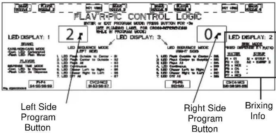
Control Board Label
PLACING A CONTROL BOARD INTO BRIX MODE
NOTE: See Program Mode 2 for Program Mode Operations.
- Prior to brixing be sure all water and syrup lines are connected to the system and purged. Ensure that syrup and water are available.
- If the merchandiser and splash panel are on the front of the unit, remove them. Merchandiser removal will give you access to the syrup and water valves. Splash panel removal will give you access to the plumbing label located on the foam front and/or see the Diagrams section of this manual. This label will be needed to identify valve and touch pad locations.
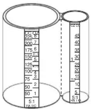
5:1 Brix Cup
- Use a standard brix cup with a 5:1 ratio for the procedure. An example is illustrated above. Use of a funnel between the cup and nozzle may aid in the capture of the syrup during syrup brixing.
| Left Board Right Board | ||
| Dispense Type and Valve Number | C1 - Valve 8 C3 - | Valve 4 |
| C2 - Valve 11 C4 - | Valve 1 | |
| NC2 - Valve 11 NC3 - | Valve 4 | |
| S1 - Valve 8 S9 - | Valve 15 | |
| S2 - Valve 9 S10 - | Valve 3 | |
| S3 - Valve 9 S11 - | Valve 3 | |
| S4 - Valve 14 S12 - | Valve 7 | |
| S5 - Valve 14 S13 - | Valve 7 | |
| S6 - Valve 10 S14 - | Valve 2 | |
| S7 - Valve 10 S15 - | Valve 2 | |
| S8 - Valve 15 S16 - | Valve 1 | |
| F1 - Valve 13 F5 - | Valve 6 | |
| F2 - Valve 13 F6 - | Valve 6 | |
| F3 - Valve 12 F7 - | Valve 5 | |
| F4 - Valve 12 F8 - | Valve 5 | |
| C = Carb NC = Non-Carb S = Syrup F = Flavor Shot | ||
- Locate the control board that corresponds with the valve(s) and/or dispense point you want to brix.
- Press the program button and hold for 3 seconds or until the LED displays 1. Press the program button again until 2 is displayed on the control board LED display.
NOTE: Programming one board at a time will make it easier for you to identify the corresponding valves and dispense points. See Flav'R-Pic External Programming in this manual for more detail on all programming modes.
- With a board in Mode 2 you can now brix any water or syrup valve that corresponds to the board. Use the chart above to identify the valves and which board they correspond to. See the illustration that follows for more assistance. Brixing information can also be found on the right hand side of the control board cover label. By using this label in combination with the plumbing label you will be able to identify each valve, water, and/or syrup combination.
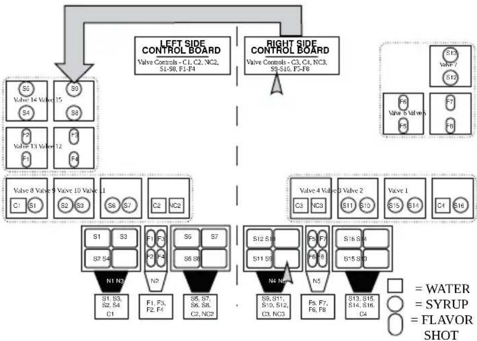
flowchart
graph TD
    A["LEFT SIDE CONTROL BOARD\nValve Controls - C1, C2, NC2, S1-S8, F1-F4"] --> B["Left Side Control Board\nValve Controls - C3, C4, NC3, S9-S16, F5-F8"]
    A --> C["Right Side Control Board\nValve Controls - C3, C4, NC3, S9-S16, F5-F8"]
    D["Valve 1"] --> E["Valve 2"]
    D --> F["Valve 3"]
    D --> G["Valve 4"]
    D --> H["Valve 5"]
    D --> I["Valve 6"]
    D --> J["Valve 7"]
    D --> K["Valve 8"]
    D --> L["Valve 9"]
    D --> M["Valve 10"]
    D --> N["Valve 11"]
    D --> O["Valve 12"]
    D --> P["Valve 13"]
    D --> Q["Valve 14"]
    D --> R["S5\nS4\nF2\nF1\nF3\nF4\nC1\nS1\nS2\nS3\nS6\nS7\nC2\nNC2\nN1 N3\nS1,S3,\nS2,S4\nC1\nF1,F3,\nF2,F4\nS6,S7,\nS6,S8,\nC2,NC2\nN2\nS6,S7,\nS6,S8,\nC2,NC2\nN4 No\nS8,S11,\nS10,S12,\nC3,NC3\nF5,F7,\nF6,F8\nS13,S15,\nS14,S16,\nC4\n= WATER\n= SYRUP\n= FLAVOR SHOT"]
S9 (Syrup 9) on Valve 15 is the only syrup that does not correspond to the side it is mounted to. Both visually and functionally all other valves, touch pads, and dispense points correspond with the board on the same side to which they are attached.
GENERAL BRIXING PROCESS
- With the corresponding control board set to brix mode and displaying a 2 you may brix a beverage nozzle (NI, N3, N4, or N6). If brixing a syrup, the use of a funnel between the cup and nozzle may aid in the capture of the syrup. (See nozzle order below.)
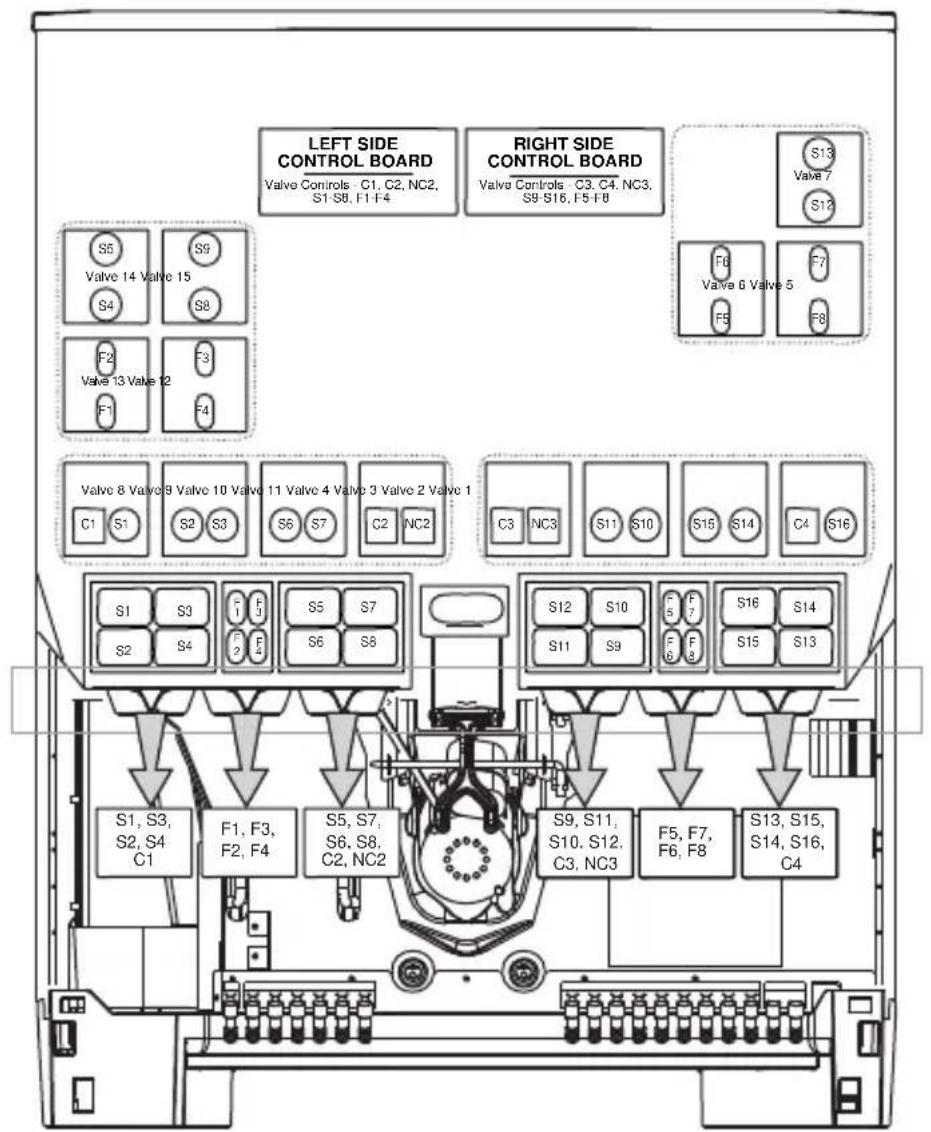
flowchart
graph TD
    subgraph Left Side Control Board
        A["S5"] --> B["Valve 14 Valve 15"]
        C["S9"] --> D["Valve 13 Valve 12"]
        E["F2"] --> F["Valve 13 Valve 12"]
        G["F3"] --> H["Valve 13 Valve 12"]
        I["S4"] --> J["Left Side Control Board"]
        K["S8"] --> L["Valve 14 Valve 15"]
        M["S7"] --> N["Valve 13 Valve 12"]
        O["S8"] --> P["Left Side Control Board"]
        Q["S5"] --> R["Valve 8 Valve 8 Valve 10 Valve 11 Valve 4 Valve 3 Valve 2 Valve 1"]
        S["S7"] --> T["Left Side Control Board"]
        U["C2"] --> V["Valve 8 Valve 8 Valve 10 Valve 11 Valve 4 Valve 3 Valve 2 Valve 1"]
        W["C2"] --> X["Left Side Control Board"]
        Y["S6"] --> Z["Valve 8 Valve 8 Valve 10 Valve 11 Valve 4 Valve 3 Valve 2 Valve 1"]
        AA["S7"] --> AB["Left Side Control Board"]
        AC["S6"] --> AD["Valve 8 Valve 8 Valve 10 Valve 11 Valve 4 Valve 3 Valve 2 Valve 1"]
        AE["S8"] --> AF["Left Side Control Board"]
        AG["S1"] --> AH["Valve 8 Valve 8 Valve 10 Valve 11 Valve 4 Valve 3 Valve 2 Valve 1"]
        AI["S3"] --> AJ["Left Side Control Board"]
        AK["S2"] --> AL["Valve 8 Valve 8 Valve 10 Valve 11 Valve 4 Valve 3 Valve 2 Valve 1"]
        AM["S3"] --> AN["Left Side Control Board"]
        AO["S4"] --> AP["Valve 8 Valve 8 Valve 10 Valve 11 Valve 4 Valve 3 Valve 2 Valve 1"]
        AQ["S5"] --> AR["Left Side Control Board"]
        AS["S7"] --> AT["Valve 8 Valve 8 Valve 10 Valve 11 Valve 4 Valve 3 Valve 2 Valve 1"]
        AU["S7"] --> AV["Left Side Control Board"]
        AW["S6"] --> AX["Valve 8 Valve 8 Valve 10 Valve 11 Valve 4 Valve 3 Valve 2 Valve 1"]
        AY["S5"] --> AZ["Left Side Control Board"]
        BA["S9"] --> BB["Valve 6 Valve 5"]
        BC["S10"] --> BD["Valve 6 Valve 5"]
        BE["S11"] --> BF["Valve 6 Valve 5"]
        BG["S12"] --> BH["Valve 6 Valve 5"]
        BI["S13"] --> BJ["Valve 6 Valve 5"]
        BK["S14"] --> BL["Valve 6 Valve 5"]
        BM["S15"] --> BN["Valve 6 Valve 5"]
        BO["S16"] --> BP["Valve 6 Valve 5"]
    end
    style LeftSideControlBoard fill:#f9f,stroke:#333
    style RightSideControlBoard fill:#f9f,stroke:#333
Nozzles from left to right: N1, N2, N3, N4, N5, N6
- To brix carbonated or non-carbonated water for a dispense point, leave the nozzle in place and hold the brix cup with the water side of the cup under the nozzle area. Non-carbonated water is only available at N3 (Nozzle 3) and N4.
-
By referencing the control box label and plumbing diagram, press the flavor shot touch pad that corresponds with the water you wish to brix. If brixing the left side, it will be one of the following; F1 (Flavor Shot 1), F2, or F3. When brixing the right side, F5, F6, or F7 will be used. On non-flavor shot units, the touch pads are located behind the merchandiser on the foam front.
-
The correct volume should be 5 oz. (147.86 cc) during the fixed dispense in Mode 2. If adjustment is needed to attain this volume, make adjustments to the left side of valve 8 (C1) adjustment screw as needed until flow rate is satisfactory.
NOTE: The touch pad mount can be tilted forward in order to give you better access to the valves.
-
For syrup brixing place the brix cup with the syrup side of the cup under the nozzle area and press any brand touch pad area associated with that nozzle dispense point. For example S1 (Syrup 1), S2, S3, and S4 touch pad areas will be used to brix N1 (Nozzle 1).
-
Syrup will dispense for a fixed duration and should be even with the 5 oz. (147.86 cc) water mark on the cup, or 1 oz (29.57cc) just below the 30cc mark on the syrup side of the brix cup.
-
Check each syrup position and adjust syrup on the corresponding valve as necessary. A plumbing label is located on the foam front of the unit showing the position of each valve and syrup port. See the plumbing diagram.
-
When finished, move on to another nozzle or, if your brixing is complete, return the control board to the dispense mode by pressing the program button and holding for 3 seconds or until the LED displays 0. Replace the splash panel and merchandiser.
Nozzle 1 (N1) Water & Syrup Brixing
- With the left control board set to brix mode and displaying a 2 you can now brix the carbonated water for N1 (Nozzle 1) located at the far left hand side of the unit.
- To brix the carbonated water for this dispense point leave the nozzle in place, hold the brix cup with the water side of the cup under N1 (Nozzle 1), and press the F1 (Flavor Shot 1) button. Water will dispense for a fixed duration.
- The correct volume should be 5 oz. (147.86 cc). If adjustment is needed to attain this volume, make adjustments to the left side of valve 8 (C1) adjustment screw as needed until flow rate is satisfactory.
- For syrup brixing place the brix cup with the syrup side of the cup under the N1 and press the touch pad area for S1 (Syrup 1), S2, S3, or S4, and the corresponding syrup will dispense for a fixed duration.
- Syrup should be even with the 5 oz. (147.86 cc) water mark on the cup, or 1 oz (29.57cc) just below the 30cc mark on the syrup side of the brix cup.
- Check each syrup position and adjust syrup on the corresponding valve as necessary. A plumbing label is located on the foam front of the unit showing the position of each valve and syrup port. See the plumbing diagram.
- Move to another nozzle or, if you are finished brixing, return the control board to the dispense mode by pressing the program button and holding for 3 seconds or until the LED displays 0. Replace the splash panel and merchandiser.
Nozzle 2 (N2) Water & Syrup Brixing
This is a flavor shot dispense point, designated so by its blue nozzle, no brixing is needed. Either a 1 or 2 second dispense duration can be selected in program Mode 1 from the left side control board. (See Flav'R-Pic External Programming for more information.)
Nozzle 3 (N3) Carb/Non-Carb Water & Syrup Brixing
- With the left control board set to brix mode and displaying a 2 you can now brix carbonated or non-carbonated water for N3 (Nozzle 3). (See Program Mode 1 to designate carb/non-carb.)
- To brix the carbonated water for this dispense point, leave the nozzle in place, hold the brix cup with the water side of the cup under N3 (Nozzle 3), and press the F2 (Flavor Shot 2) button. Carbonated water will dispense for a fixed duration.
- To brix the non-carbonated water for this dispense point leave the nozzle in place, hold the brix cup with the water side of the cup under N3 (Nozzle 3), and press the F3 (Flavor Shot 3) button. Water will dispense for a fixed duration.
- The correct carb and non-carb volume should be 5 oz. (147.86 cc). If adjustment is needed to attain this volume, make adjustments to the left side of valve 11 (C2) adjustment screw for carbonated water and the right side of valve 11 (NC2) adjustment screw for non-carbonated water as needed until flow rate is satisfactory.
- For syrup brixing place the brix cup with the syrup side of the cup under the N3 (Nozzle 3) and press the touch pad area for S5 (Syrup 5), S6, S7, or S8 and the corresponding syrup will dispense for a fixed duration.
-
Syrup should be even with the 5 oz. (147.86 ml) water mark on the cup, or 1 oz (29.57cc) just below the 30cc mark on the syrup side of the brix cup.
-
Check each syrup position and adjust syrup on the corresponding valve as necessary. A plumbing label is located on the foam front of the unit showing the position of each valve and syrup port. See the plumbing diagram.
-
Move to another nozzle or, if you are finished brixing, return the control board to the dispense mode by pressing the program button and holding for 3 seconds or until the LED displays 0. Replace the splash panel and merchandiser.
Nozzle 4 (N4) Carb/Non-Carb Water & Syrup Brixing
- With the right control board set to brix mode and displaying a 2, you can now brix carbonated or non-carbonated water for Nozzle 4 (N4). (See Program Mode 1 to designate carb/non-carb.)
- To brix the carbonated water for this dispense point, leave the nozzle in place, hold the brix cup with the water side of the cup under N4 (Nozzle 4), and press the F6 (Flavor Shot 6) button. Water will dispense for a fixed duration.
- To brix the non-carbonated water for this dispense point, leave the nozzle in place, hold the brix cup with the water side of the cup under N4 (Nozzle 4), and press the F7 (Flavor Shot 7) button. Water will dispense for a fixed duration.
- The correct carb and non-carb volume should be 5 oz. (147.86 ml). If adjustment is needed to attain this volume, make adjustments to the left side of valve 11 (C3) adjustment screw for carbonated water and the right side of valve 4 (NC3) adjustment screw for non-carbonated water as needed until flow rate is satisfactory.
- For syrup brixing place the brix cup with the syrup side of the cup under the N4 (Nozzle 4) and press the touch pad area for S9 (Syrup 9), S10, S11, or S12 and the corresponding syrup will dispense for a fixed duration.
-
Syrup should be even with the 5 oz. (147.86 cc) water mark on the cup, or 1 oz (29.57cc) just below the 30cc mark on the syrup side of the brix cup.
-
Check each syrup position and adjust syrup on the corresponding valve as necessary. A plumbing label is located on the foam front of the unit showing the position of each valve and syrup port. See the plumbing diagram.
-
Move to another nozzle or, if you are finished brixing, return the control board to the dispense mode by pressing the program button and holding for 3 seconds or until the LED displays 0. Replace the splash panel and merchandiser.
Nozzle 5 (N5) Water & Syrup Brixing
This is a flavor shot dispense point, designated so by its blue nozzle, no brixing is needed. Either a 1 or 2 second dispense duration can be selected in program Mode 1 from the right side control board. (See Flav'R-Pic External Programming for more information.)
Nozzle 6 (N6) Water & Syrup Brixing
- With the right control board set to brix mode and displaying a 2 you can now brix the carbonated water for N6 (Nozzle 1) located at the far right hand side of the unit).
- To brix the carbonated water for this dispense point, leave the nozzle in place, hold the brix cup with the water side of the cup under N6 (Nozzle 6), and press the F5 (Flavor Shot 5) button. Water will dispense for a fixed duration.
- The correct volume should be 5 oz. (147.86 cc). If adjustment is needed to attain this volume, make adjustments to the left side of valve 1 (C4) adjustment screw as needed until flow rate is satisfactory.
- For syrup brixing place the brix cup with the syrup side of the cup under the N6 (Nozzle 6) and press the touch pad area for S13 (Syrup 13), S14, S15, or S16, and the corresponding syrup will dispense for a fixed duration.
-
Syrup should be even with the 5 oz. (147.86 cc) water mark on the cup, or 1 oz (29.57cc) just below the 30cc mark on the syrup side of the brix cup.
-
Check each syrup position and adjust syrup on the corresponding valve as necessary. A plumbing label is located on the foam front of the unit showing the position of each valve and syrup port. See the plumbing diagram.
-
Move to another nozzle or, if you are finished brixing, return the control board to the dispense mode by pressing the program button and holding for 3 seconds or until the LED displays 0. Replace the splash panel and merchandiser.
FlexTower Programming Modes
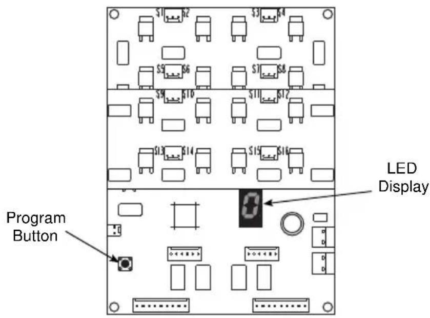
CONTROL BOARD RUN OR DISPENSE MODE
(Control Board LED Displays 0)
For finished drink, press and hold any labeled finished drink touchpad area to manually dispense a finished noncarbonated drink (all touchpad areas are defaulted from factor to manual dispense mode). For flavor adder, press any labeled flavor adder touchpad area and a one shot stored timed dispense will occur (dispense time of flavor adder can be changed in program mode 2).
THE 6 PROGRAMMING MODES ON FLEXTOWER CONTROL BOARD
Program Mode 1= Manual Dispense Mode
Program Mode 2= Timed Dispense Mode or Flavor Adder Mode
Program Mode 3= Water Calibration Mode
Program Mode 4= Syrup Calibration Mode
Program Mode 5= Touchpad Configuration Mode
Program Mode 6= Touchpad LED Light Sequencing Mode
To Access Programming Modes
To enter programming modes, press and hold the control board program button for a minimum of 3 seconds. Control board LED displays a number (1) for manual dispense mode. To select another programming mode, press and release the control board program button once to enter the next programming mode. Repeat pressing and releasing the control board program button until desired program mode is entered.
To Exit Programming Modes
To exit programming modes and to save programming mode changes, press and hold control board program button for a minimum of 3 seconds. Control board LED displays (0) for run or dispense mode.
Manual Dispense Mode
(Finished Noncarbonated Drink Dispensed)
Once in program mode (1), the control board LED displays (1). Press any touchpad selection area two times in less than three seconds and selection area LED lights will blink twice to indicate the touchpad area has been programmed for manual dispense. The procedure can be repeated for other touchpad selection areas needing programmed for manual dispense. After all designated touchpad areas have been programmed for manual dispense either enter another program mode or exit the programming modes, which will save programming mode changes.
Timed Dispense Mode (Flavor Adder Dispensed)
Once in program mode (2), the control board LED displays (2). Press any touchpad selection area three times in less than three seconds and selection area LED lights will blink three times to indicate the touchpad area has been programmed for timed dispense. Then the first and last touchpad selection areas will illuminate, which will allow increasing the timed dispense cycle by .2 seconds each press of the last illuminated touchpad selection area or decreasing the timed dispense cycle by .2 seconds each press of the first illuminated touchpad selection area. To program another touchpad area for timed dispense, press and release the control board program button to reset the timed dispense programming mode, first and last touchpad areas are no longer illuminated. Repeat procedures for programming timed dispense for other designated touchpad selection areas. After all designated touchpad areas have been programmed for timed dispense, either enter another program mode or exit the programming modes, which will save programming mode changes.
Water Calibration Mode
Once in program mode (3), the control board LED displays (3). Press any touchpad selection area and the noncarbonated water valve will dispense for three seconds in order to brix the valve. The procedure can be repeated as many times as necessary in order to brix the noncarbonated water valve. After the water valve has been brixed, either enter another program mode or exit the programming modes, which will save programming mode changes.
Syrup Calibration Mode
Once in program mode (4), the control board LED displays (4). Press any touchpad selection area and the associated syrup valve circuit will dispense for three seconds in order to brix the syrup valve circuit. The procedure can be repeated as many times as necessary in order to brix all syrup valve circuits. After all syrup valve circuits have been brixed, either enter another program mode or exit the programming modes, which will save programming mode changes.
Touchpad Configuration Mode
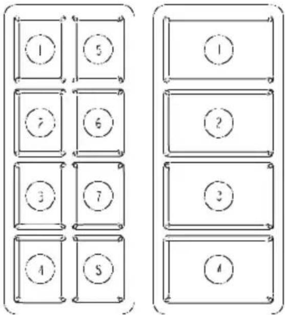
8 Selection Area 4 Selection Area
Once in program mode (5), the control board LED displays (5). Press the first and last touchpad selection areas on both touchpads. The touchpad LED lights sequence through all the touchpad selection areas indicating the touchpad has been configured. After configuring both touchpads, either enter another program mode or exit the programming modes, which will save programming mode changes.
Touchpad LED Light Sequencing Mode (8 Selection Area Touchpad)
Once in program mode (6), the control board LED displays (6). Press the first touchpad selection areas on either touchpad for clockwise LED light sequencing. The touchpad LED lights sequence clockwise through all the touchpad selection areas indicating the touchpad has been configured for clockwise LED light sequencing. Or press the second touchpad selection areas on either touchpad for counterclockwise LED light sequencing. The touchpad LED lights sequence counterclockwise through all the touchpad selection areas indicating the touchpad has been configured for counterclockwise LED light sequencing. Or press the third touchpad selection area on either touchpad to turn off LED light sequencing. The third touchpad area LED lights illuminate for 3 seconds then turn off indicating the
touchpad has been configured for LED light sequencing off mode. After configuring the LED light sequencing for touchpads, either enter another program mode or exit the programming modes, which will save programming mode changes.
Touchpad LED Light Sequencing Mode (4 Selection Area Touchpad)
Once in program mode (6), the control board LED displays (6). Press the first touchpad selection areas on either touchpad for upward LED light sequencing. The touchpad LED lights sequence upward through all the touchpad selection areas indicating the touchpad has been configured for upward LED light sequencing. Or press the second touchpad selection areas on either touchpad for downward LED light sequencing. The touchpad LED lights sequence downward through all the touchpad selection areas indicating the touchpad has been configured for downward LED light sequencing. Or press the third touchpad selection area on either touchpad to turn off LED light sequencing. The third touchpad area LED lights illuminate for 3 seconds then turn off indicating the touchpad has been configured for LED light sequencing off mode. After configuring the LED light sequencing for touchpads, either enter another program mode or exit the programming modes, which will save programming mode changes.
Adjustments
QUICKDRAW ICE PORTION ADJUSTMENTS
The Quickdraw ice dispensing system has adjustable ice portion sizes. Follow the directions below to set the ice portion size. Each portion size must be checked according to customer specification at the time of installation.
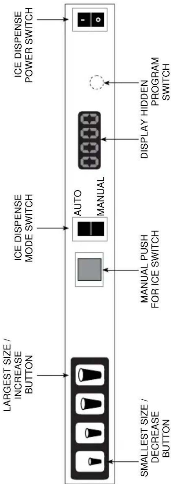
flowchart
graph LR
    A["LARGEST SIZE / INCREASE BUTTON"] --> B["SMALLEST SIZE / DECREASE BUTTON"]
    C["ICE DISPENSE MODE SWITCH"] --> D["MANUAL PUSH FOR ICE SWITCH"]
    E["ICE DISPENSE POWER SWITCH"] --> F["DISPLAY HIDDEN PROGRAM SWITCH"]
    G["AUTO MANUAL"] --> D
    G --> F
-
To set the ice portion sizes, press the program switch 1 time in 3 seconds. The display will read "0001".
-
Press the ice portion size that is to be adjusted. Once the portion size that is to be adjusted is pressed, the display will show the present pulse setting for that size.
-
To increase the portion size, press the largest size button. To decrease the portion size, press the smallest size button.
NOTE: The pulse count will increase, or decrease, by 1 with each press of the smallest or largest size buttons.
-
Press the program button 1 time to exit program mode and save settings.
-
Repeat steps 1 through 4 for each cup size as necessary.
NOTE: For Data Display Mode, and Test Mode instructions please refer to the Quickdraw Portion Control Program flow chart in this manual.
Free movement of the metering wheel is essential for consistent ice portion sizes.
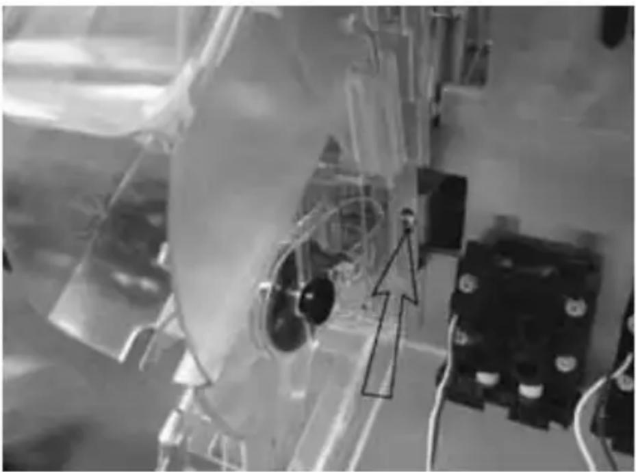
natural_image
Close-up of a mechanical assembly with transparent components and wiring (no visible text or symbols)One Adjustment Screw on Each Side of QD Assembly
The Quickdraw assembly is adjustable to assure the wheel will always move freely. The assembly has two adjustment screws that can be adjusted in or out to align where the ice wheel axle goes through the sensor board and the ice chute.
ROCKING CHUTE ICE DELIVERY SWITCH ADJUSTMENT
To properly adjust the switch, first unplug the power cord to the unit then remove the merchandiser. This will give you access to the ice delivery switch located on the left side of the rocking chute.
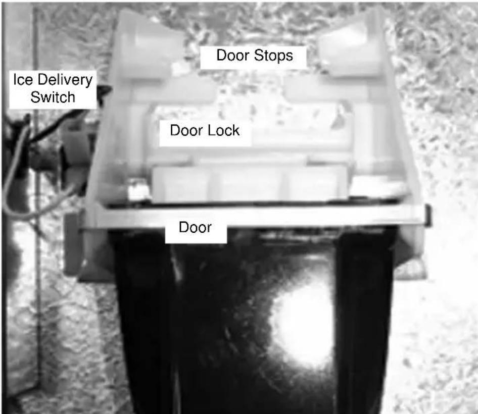
Begin by observing the chute by slowly pushing against the rocking chute. When the ice delivery switch clicks, measure the distance from the door stops on the rocking chute bracket to the door. The distance between the two must be no more than 1/4" (0.64 cm), but no less than 1/16" (0.16 cm).
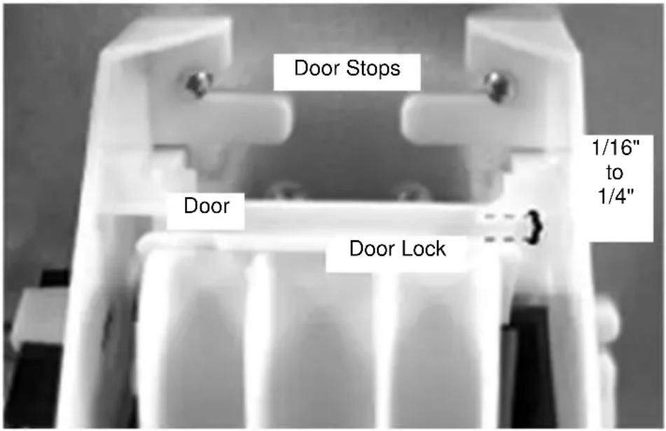
The left side of the rocking chute has a tab that pushes up on the ice delivery switch. To adjust it, use needle nose pliers and bend the arm of the switch up or down in order to change the point where the tab makes contact with the switch arm.
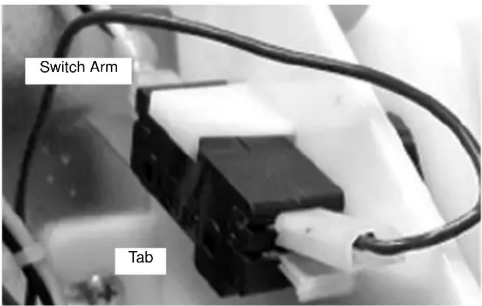
Agitation Timer
The timer is non-adjustable and is set to agitate the ice for 3 seconds every 3.5 hours. Activating the dispenser will reset the timer. After 3.5 hours of non-use, the timer will energize the dispenser motor.
The LED tells the technician in which mode the timer is operating. Rather than a jumper pin, this timer has a female spade connector that must be connected to terminal number 6.
When this jumper is in place, the LED will blink at one-second intervals, this is the run mode.
When the jumper is open, the LED will flash every 0.4 second. This is the test mode and the timer will cycle every 55 seconds in test mode. If the timer is left in test mode, it will automatically reset to run mode.
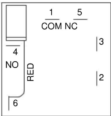
Agitation Timer
Troubleshooting
This Troubleshooting section has been developed to assist you in determining what the probable cause for any particular problem you may experience with your ice/beverage system could be. It then advises of the proper corrective action to be taken to remedy that problem.
Because of the ever present danger from electrical shock, and the existence of high pressure water and gas on the system, it is strongly recommended that only qualified service personnel perform actual repairs.
Checklist
If a problem arises during operation of your dispenser, follow the checklist below. Routine adjustments and maintenance procedures are not covered by the warranty.
| Problem Possible Cause To Correct | ||
| Dispenser will not dispense ice (and NO SOUNDS are heard when machine is activated) | No power Check | electrical connection. |
| Loose wire in electrical system | Thoroughly check all wire connections. | |
| Dispenser overloaded with ice | Remove ice from dispenser until unit will operate. | |
| Motor not working Check thermally protected motor. Replace motor or capacitor if necessary. | ||
| Dispenser will not dispense ice (motor runs but no ice movement is heard in bin) | No ice in bin Fill dispenser with ice. | |
| Door not opening Check rocking chute mechanism or electric solenoid operation. | ||
| Paddle wheel pin slipped from the paddle wheel | Replace paddle wheel pin. | |
| Excessive clustering or bridging of ice | Loaded ice not broken up. (Caution: Super cooled ice is not covered by the warranty.) | Break ice clusters before manually filling the dispenser. (See ice recommendations.) |
| Excessive water spilling from the ice machine | Adjust ice machine to eliminate water spillage. | |
| Poorly adjusted ice machine | Adjust ice machine to eliminate large waffle shapes. | |
| Extremely low usage of the dispenser | Lower the ice level in the bin. | |
| Ice dispenses continuously | Misaligned microswitch | Adjust microswitch. |
| Agitation timer set incorrectly | Test agitation timer. | |
| Thumping noise or irregular sound at a particular area of the dispenser | Shaved ice clusters in the bin | Remove clusters, discover why ice is shaving, and then repair. |
| Dispensing crushed ice or reduced dispensing speed | Water spillage from ice machine into dispenser bin | Adjust ice machine. |
| Agitation timer (FRP-250) | Test agitation timer. | |
| Bridge of ice sheet is too thick | Adjust ice machine. | |
| Paddle wheel area broken or cracked | Replace paddle wheel area. | |
| Ice clusters in bin Break up or remove clusters. | ||
| Door not fully open Adjust door. | ||
| Door will not close Ice jammed in chute Adjust bridge in ice machine or, when manually filling, break up clusters. | ||
| Mounting brackets for rocking chute have spread too far apart | Stretched during removal for cleaning or maintenance | Bend parts into shape. |
DRINKS
| Condition Investigation Check Correction | |||
| Warm drinks Is the compressor running? No | Power switch off or Compressor switch off | Move switch to ON position. | |
| Ice bank control (CEV) | Check / replace control box. | ||
| Compressor overload | Check / replace overload. | ||
| Start relay Check / replace relay. | |||
| Compressor Check / replace compressor. | |||
| Note A: It is important to remember that any time the refrigeration system is opened the refrigerant should be recovered, a new drier installed and the proper charge of refrigerant weighed into the refrigeration system. | |||
| No water, syrup or gas dispensing | Is there power to the unit? | No power Plug in unit or reset breaker. | |
| Is power coming through the key switch? | Power to control box | Replace fuse or control box. | |
| Is there power to the key switch? | Key switch OFF Turn switch ON. | ||
| Key switch defective | Replace key switch. | ||
| No power through the transformer | Reset/replace transformer. | ||
| Water only dispensing | No pressure Regulator(s) out of adjustment | Check/adjust regulator(s). | |
| Install fresh tank. | |||
| Check/repair/replace regulator(s). | |||
| Check/repair/replace CO2 line. | |||
| Syrup and CO2 only dispensing | Carbonator No power Check power supplyPlug in carbonator or reset breaker. | ||
| Syrup and plain water only dispensing | No pressure Out | of CO2 | Install fresh tank. |
| HP regulator out of adjustment | Adjust HP regulator to the proper setting. | ||
| Defective HP regulator | Check/repair/replace HP regulator. | ||
| CO2line pinched, kinked or obstructed | Check/repair/replace CO2line. | ||
| One valve will not dispense anything | Is there power to the valve? | Broken wire or loose connection | Replace/repair wire or connector. |
| Bad microswitch | Replace microswitch. | ||
| Beverage dispensed is too sweet | Is the ratio (brix) of the drink correct? | Flow control out of adjustment | Adjust the flow control. |
| Insufficient soda flow due to low carbonator pressure | Adjust CO2pressure or change the tank. | ||
| Low CO2pressure due to leaks | Repair CO2leaks. | ||
| Obstruction in the water or soda line | Clean out the lines. | ||
| Beverage is not sweet enough | Is the ratio (brix) of the drink correct? | Flow control out of adjustment | Adjust the flow control. |
| Soda flow too high | Reset CO2pressure or replace regulator if necessary. | ||
| Obstruction in syrup line | Clean out the syrup line. | ||
| Drinks are foaming | Are system pressures correct? | Over carbonation | Check CO2supply. Reset pressure or replace regulator if necessary. |
| Dirty lines/ valves | Clean/sanitize entire system. | ||
PUMP
| Problem Possible Cause Correction | ||
| Pump motor does not pump | Black and/or red probe shorted | Remove probes and bend straight or replace with new probe(s). |
| Problem with motor or motor wiring | Check line voltage first. Check AC voltage across load terminals on Liquid Level Control. If voltage is 120 plus or minus 10%, replace motor or motor wiring. | |
| Problem with Liquid Level Control Board | Check line voltage first. If AC voltage across load terminals is not 120 plus or minus 10%, replace the Liquid Level Control Board. | |
| Water pressure from water source is not high enough | Verify water pressure leading into pump inlet is 40 psi minimum with pump running. | |
| Pump will not run but tank appears to be always full | Common Lead (Green) shorted out to Red wire (High Probe) | Verify Green and Red wires are not touching. |
| Pump will not run but tank level appears to be below start level | Common Lead (Green) shorted out to Black wire (Low Probe) | Verify Green and Black wires are not touching. |
| Pump motor does not shut off | Problem with Liquid Level Control Board | Short the “H & L” terminals on the Liquid Level Control Board. If motor does not shut off, replace Liquid Level Control Board. |
| Probe Harness Connection may be open | Verify connections are good or replace the wiring harness. | |
| Water may not be reaching top probe in carb tank | Verify tank is not filled with CO2 or air by pulling relief valve up and letting air escape until water begins coming out. | |
| High Lead (Red) open or not connected | Verify Red lead wire is connected from tank to unit. | |
| Common lead (Green) open or not connected | Verify Green lead wire is connected from tank to unit. | |
| Pump motor intermittent | Problem with probe or probe harness | Check motor and motor wires by removing red and black wires from the Liquid Level Control Board. If okay, short “H & L” terminal on Liquid Level Control Board. If motor stays off, verify probes and bend straight or replace. Verify with meter. |
| Problem with motor or motor wiring | Measure AC voltage across load terminals on Liquid Level Control Board. If line voltage is 120 plus or minus 10% replace motor or motor wiring. | |
| Pump motor intermittent | Problem with Liquid Level Control Board | Check line voltage first. If AC voltage across load terminals on Liquid Level Control Board is not 120 plus or minus 10%, replace the Liquid Level Control board. |
| Pump motor starts and stops, short cycles, as soon as water level drops below Red (High) probe | Black (Low) Lead wire is open or disconnected | Verify connections and continuity of black wire from Liquid Level Control Board to Probes on Carb Tank. |
| Pump motor starts and stops, short cycles, as soon as water level drops below Black (Low) probe | Red and Black Leads are switched with each other | Verify Red Lead is going to Red probe and Black Lead is going to Black probe. |
| Pump short cycles from below high probe to just above high probe - Low probe has no effect | Red and Green Leads are switched with each other | Verify Red Lead is going to Red Probe and Green Lead is going to Ground Screw on tank |
| Black and Green Leads are switched with each other | Verify Black Lead is going to Black Probe and Green Lead is going to Ground Screw on tank. | |
BLADE TOWER
| Condition Investigation Check Correction | |||
| Water Only Dispensing | No Pressure BNB Fittings Clogged Tank Fittings Clogged No Power | Clean and Sanitize. Clean and Sanitize. Check Power Supply. | |
| Syrup and CO_2 only Dispensing | Carbonator Check Liquid Level Control Board For Clogging | Replace Control. | |
| One Valve will not dispense anything | Pre-Mix Valve (CMBecker) Post-Mix Valve (Flomatic 424) | For Mechanical For Clogging For Mechanical | Clean and Sanitize. Replace if Necessary. Clean and Sanitize. |
| Beverage Dispense is too sweet or Drinks are Foaming | Are system pressures correct | Syrup Push Pressure | Replace parts or entire valve if necessary. |
| Drink Stratification too great | Visually verify Soda, Water and Syrup flowing at the same time in mixer block, when initially dispensing | Check Valves in Water and Product Lines. If soda water check valve is bad, Syrup will overcome soda water when first dispensing product. If syrup check valve is bad, soda water will overcome syrup flow when first dispensing product. | Adjust to 30-40 PSI per Tower Manual. Lower equals less foaming. Too low will limit flow volume. Replace check valve(s). |
FLEXTOWER
| Condition Investigation Check Correction | |||
| No power at unit | Electrical circuit ON/OFF switch Switch to ON position/replace defective switch. | ||
| Control board inoperative | Check/replace control board. | ||
| Board/ bracket lights inoperative | Light modules Inoperative light modules | Replace modules. | |
| Control board Control board programming | Check and program/ reprogram. | ||
| Water only dispensing (one or more flavors)-- | Syrup circuit Syrup supply depleted | Replenish syrup supply. | |
| Adjust syrup pressure to 40 PSI (2.75 BAR). | |||
| B-I-B connector off Reattach B-I-B connector. | |||
| B-I-B connector plugged | |||
| Syrup line restricted | |||
| Syrup outlet plugged at valve | |||
| Syrup port plugged at injection shroud | |||
| Outlet syrup line off valve | |||
| Syrup solenoid inoperative | |||
| Check power to solenoid. Check/replace solenoid. Check connection to control board. | |||
| Control board inoperative | |||
| Syrup only dispensing | Water circuit No | water pressure Check | source water supply. |
| Water pressure too low | Have location check plumbing and/or install water booster unit. | ||
| Water line restricted | Check water line from water source. | ||
| Water lines off water pump | Reattach water lines. | ||
| Water lines off heat exchanger | Reattach water lines. | ||
| Water lines off tee connection in unit | Reattach water lines. | ||
| Water valve solenoid inoperative | Check power to solenoid.Check/replace solenoid.Check connection to control board.Check/replace control board. | ||
| Noisy syrup/water valve solenoid | Syrup/water valves | Defective solenoid | Replace solenoid. |
| Finished drink taste too sweet/not sweet enough | Finished drink brix incorrect | Check brix ratio as specified by syrup manufacturer | Brix finished drink. |
| Syrup/water leaks | Syrup and water circuits | Check water/syrup connections and components | Tighten connections.Replace leaking components. |
| Problem Possible Cause Corrective | Action | |
| Flavor shot syrup does not dispense when flavor button is pressed | Syrup supply depleted | Replace syrup. |
| CO_2 supply depleted | Replace CO_2 . | |
| B-I-B disconnect loose or packed with dried syrup residue | Tighten and/ or clean B-I-B disconnect. | |
| CO_2 Regulator set to low | Check CO_2 regulator for proper setting — 30 PSI (1 Bar) or according to line run. | |
| Kinked CO_2 or syrup line | Check lines for kinks. | |
| B-I-B pump inoperative | Check pumps, replace if needed. | |
| Valve solenoid inoperative | Check wiring to valve, replace solenoid. | |
| Vinyl tubing off at nozzle or at solenoid | Reconnect tubing. | |
| Vinyl tubing plugged with syrup at nozzle or at solenoid | Clean tubing and nozzle. | |
| Board not in dispense mode | Place control board into dispense mode “0”. | |
| No power to control board | Disconnected or loose wires | Check connector to transformer and corresponding control board. |
| No power to transformer | Check power supply at transformer — 24 VAC. | |
| Flavor syrup does not shut off | Check for stuck solenoid | Replace solenoid if it continues to stick. |
SELECTABLE ICE
| Problem Possible Cause To Correct | ||
| DISPENSER DOES NOT DISPENSE CRUSHED ICE Nothing is heard | No power Check | power source and power cord. |
| Loose wire in electrical system | Check wiring. | |
| Dispense switch faulty | Replace switch. | |
| Crusher Motor Faulty | Replace Motor/Gear Box. | |
| Dispenser Safety Switch Open | Assure Merchandiser is installed correctly with the safety switch in the closed position. | |
| Crusher motor hums but does not turn | Blades obstructed Check for obstructions in ice crusher housing. | |
| Motor faulty Replace motor. | ||
| Faulty start relay/ capacitor | Check relay/capacitor and replace if bad. | |
| Crusher dispense door does not open | Door solenoid faulty Replace solenoid. | |
| Loose wiring to solenoid | Check wiring. | |
| Gear box on motor G | Gear box on motor faulty | Replace Ice Crusher Motor Assembly. |
| Crusher Axle broken Replace Crusher Axle. | ||
| Crusher Motor turns but Gear Motor for Paddle wheel/ Agitator Bar does not turn | Agitator Gear Motor faulty | Replace Agitator Gear Motor. |
| Loose wiring Check wiring. | ||
| Obstruction in Ice bin stopping motor | Check for obstruction. | |
| Nothing on dispenser works | No power to dispenser | Check power source. |
| Dispenser Safety Switch opens | Assure Merchandiser is installed correctly with the safety switch in the closed position. | |
| Loose wiring Check wiring. | ||
| Difficulty inserting Blade/Hub Assembly into Crusher housing | Stationary Blades not aligned with locating slots at top and bottom of crusher housing | See Disassembly in this manual. |
| Rotating Blades not in vertical position | ||
| Ice in Crusher Housing | ||
| Crushed Ice dispenses continuously, or by itself | Ice Dispense Switch Faulty | Adjust bridge in ice machine or, when manually filling, break up clusters. |
| No flashing lights on keypad, Fluorescent light was on, crusher and whole ice dispenser will not function, transformer breaker blown. | Water shorted out wiring harness on valves only | Clean up water and reset transformer. |
MDH-302 AND 402 ICE PIC
| Condition Investigation Check Correction | |||
| Dispenser does not dispense crushed ice | Nothing is heard No | No power to dispenser | Check power source and power cord. |
| Loose wiring Check wiring. | |||
| Dispense switch faulty | Replace switch. | ||
| Crusher Motor faulty | Replace Motor/Gear Box. | ||
| Dispenser Kill Switch open | Ensure Merchandiser is installed correctly and translight is in place, holding switch in the closed position. | ||
| Crusher motor hums but does not turn | Blades obstructed Check for obstructions in ice crusher housing. | ||
| Motor faulty Replace Motor. | |||
| Faulty start relay/capacitor | Check relay/capacitor and replace if bad. | ||
| Crusher dispense door does not open | Door solenoid faulty | Replace Solenoid. | |
| Loose wiring to solenoid | Check wiring. | ||
| Motor turns, but blades do not turn | Gear box on motor Faulty | Replace Ice Crusher Motor/Gear Box. | |
| Crusher Axle broken | Replace Crusher Axle. | ||
| Crusher Motor turns but Gear Motor for Paddlewheel/ Agitator Bar does not turn | Agitator Gear Motor faulty | Replace Agitator Gear Motor. | |
| Loose wiring Check wiring. | |||
| Obstruction in Ice bin stopping motor | Check for obstruction. | ||
| Nothing on dispenser works | No power to dispenser | Close Dispenser Kill Switch. | |
| Dispenser Kill Switch open | Ensure Merchandiser is installed correctly and translight is in place, holding switch in the closed position. | ||
| Loose wiring Check wiring. | |||
| Difficulty inserting Blade/Hub Assembly into Crusher housing | Stationary Blades not aligned with locating slots at top and bottom of crusher housing | See "Cleaning the Ice Crusher Assembly" in the Maintenance section of this manual. | |
| Rotating Blades not in vertical position | |||
| Check for ice in Crusher Housing | |||
| Crushed Ice dispenses continuously, or by itself | Ice Dispense Switch Faulty | Replace the Ice dispense switch. | |
| Micro switch adjustment | Adjust properly. | ||
Liquid Level Control
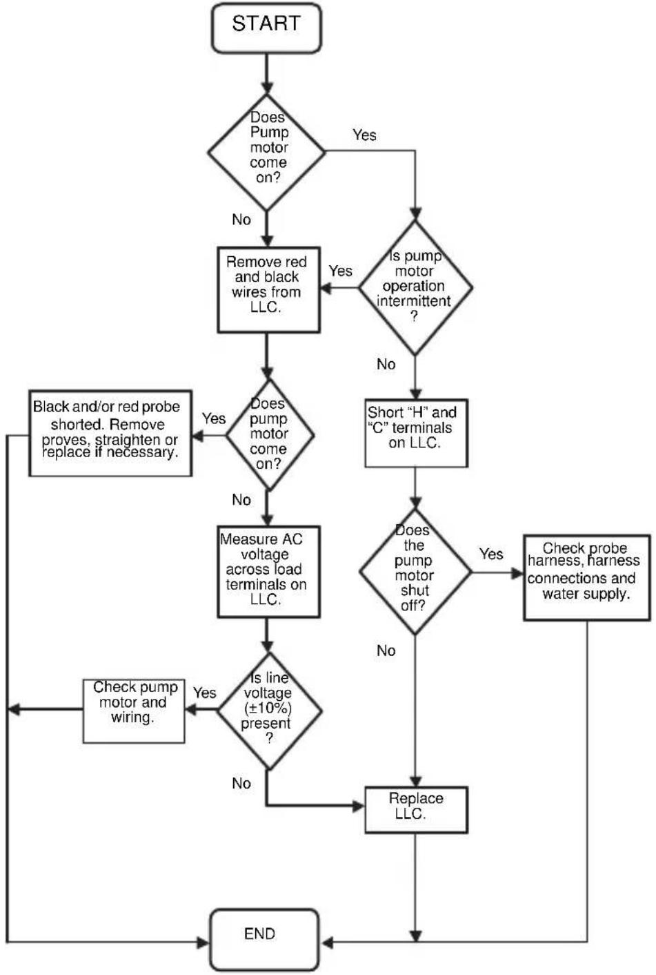
flowchart
graph TD
    A["START"] --> B{Does Pump motor come on?}
    B -->|No| C["Remove red and black wires from LLC."]
    B -->|Yes| D{Is pump motor operation intermittent?}
    D -->|Yes| E["Short "H" and "C" terminals on LLC."]
    D -->|No| F["Check probe harness, harness connections and water supply."]
    C --> G{Does pump motor come on?}
    G -->|No| H["Measure AC voltage across load terminals on LLC."]
    G -->|Yes| I["Black and/or red probe shorted. Remove proves, straighten or replace if necessary."]
    H --> J{Is line voltage (±10%) present?}
    J -->|No| K["Replace LLC."]
    J -->|Yes| L["Check pump motor and wiring."]
    K --> M["END"]
    L --> M
Diagnosing a Defective Carbonator
Go to the dispensing faucet (valve.)
- Blowing gas is a carbonator problem.
A. Unplugged
B. Pump
C. Motor
D. Switching device
E. Water off — Noisy pump
F. Filters clogged — Noisy pump
- Syrup mixing w/plain water is a pressure problem.
A. CO 2 pressure is too low
B. CO 2 cylinder is empty
C. Water pressure is too high
D. CO _2 inlet check valve is clogged
- The valve is dispensing a thin trickle of syrup with no water or gas
A. Carbonated water is frozen
B. Valve is defective

Warning
All wiring must conform to local, state and national codes.
Electrical Requirements
Refer to Ice Machine Model/Serial Plate for voltage/amperage specifications.
VOLTAGE
The standard voltage for S/SV/SVI/NGF/FRP Series dispensers is 120VAC-60Hz. A power cord is provided with 120VAC-60Hz models only. S/SV/SVI/NGF Series dispensers use a 1/7 hp gearmotor.
Minimum Circuit Ampacity
The minimum circuit ampacity is used to help select the wire size of the electrical supply. (Minimum circuit ampacity is not the beverage/ice machine's running amp load.) The wire size (or gauge) is also dependent upon location, materials used, length of run, etc., so it must be determined by a qualified electrician.
Minimum Circuit Amperage Chart
Important
Due to continuous improvements, this information is for reference only. Please refer to the dispenser serial number tag to verify electrical data. Serial tag information overrides information listed on this page.
| Dispenser Voltage/Cycle | Minimum Circuit Amps | |
| CEV-30, CEV-40 120/60 8.2 | ||
| 208-230/60, 220-240/50Hz | ||
| DI-1522, CT-6 120/60 2.4 | ||
| 220/50 | ||
| DI/DIL2323, CT-8 120/60 3.2 | ||
| 220/50 | ||
| Flavor Magic 24VAC, powered by existing valve transformer on dispenser | 0.5 | |
| FlexTower 120/60 2.5 | ||
| FRP-250 120/60 3.0 | ||
| MDH-302, MDH-402 120/60 3.5 | ||
| MDH-302SCI, MDH-402SCI | 120/60 5.4 | |
| S-150, S-200, S-250, SV-150, SV-175, SV-200, SV-250, SV-150i, SV-175i, SV-200i, SV-250i, SV-250QD, NGF-250, NGF-250QD | 115/60 2.8 | |
| 220/50, 220/60, 240/50, 240/60 | 1.5 | |
| 220-240/50 5 | (with carb deck) | |
NOTE: For FlexTower applications — A dedicated 120 VAC, 15 ampere circuit is required to provide power to the power supply's transformer with an output of 24 VAC for the electric valves, 120 VAC, 8 ampere circuit, and to power a cold water recirculation pump. The power supply has a 120 VAC outlet to provide power for the cold water recirculation pump.
Grounding Instructions

Warning
The beverage/ice machine must be grounded in accordance with national and local electrical codes.
This appliance must be grounded. In the event of malfunction or breakdown, grounding provides a path of least resistance for electric current to reduce the risk of electric shock. This appliance is equipped with a cord having an equipment-grounding conductor and a grounding plug. The plug must be plugged into an appropriate outlet that is properly installed and grounded in accordance with all local codes and ordinances.

Warning
Improper connection of the equipment-grounding conductor can result in a risk of electric shock. The conductor with insulation having an outer surface that is green with or without yellow stripes is the equipment grounding conductor. If repair or replacement of the cord or plug is necessary, do not connect the equipment-grounding conductor to a live terminal. Check with a qualified electrician or serviceman if the grounding instructions are not completely understood, or if in doubt as to whether the appliance is properly grounded. Do not modify the plug provided with the appliance — if it will not fit the outlet, have a proper outlet installed by a qualified electrician.

Warning
When using electric appliances, basic precautions must always be followed, including the following:
a. Read all the instructions before using the appliance.
b. To reduce the risk of injury, close supervision is necessary when an appliance is used near children.
c. Do not contact moving parts.
d. Only use attachments recommended or sold by the manufacturer.
e. Do not use outdoors.
f. For a cord-connected appliance, the following shall be included:
- Do not unplug by pulling on cord. To unplug, grasp the plug, not the cord.
- Unplug from outlet when not in use and before servicing or cleaning.
- Do not operate any appliance with a damaged cord or plug, or after the appliance malfunctions or is dropped or damaged in any manner. Contact the nearest authorized service facility for examination, repair, or electrical or mechanical adjustment.
g. For a permanently connected appliance — Turn the power switch to the off position when the appliance is not in use and before servicing or cleaning.
h. For an appliance with a replaceable lamp — Always unplug before replacing the lamp. Replace the bulb with the same type.
i. For a grounded appliance — Connect to a properly grounded outlet only. See Grounding Instructions.
Pump Deck Wiring
The supply cord is equipped with a three prong 5-15P. When a Ground Fault Circuit Interrupter (GFCI) is required by code, a breaker type protector must be used. We do not recommend GFIC outlets as they are known for more intermittent nuisance trips than panel breakers. To ensure both the safety and proper operation of this equipment, be certain that the electrical receptacle is a proper design so as to accept this plug, ensuring that the carbonator assembly is properly grounded.
If the pump deck is to be installed in an area or community whose local codes require permanent wiring, the following procedure must be followed.
- The three wires (white, black and green) must be fed through the cable connector and brought into the wiring compartment. The cable must be secured into the connector.
- The green wire from the cable must be connected to the green screw that attaches to the inside panel of the wiring compartment. Be sure to use a ring torque terminal for connecting the wire to the screw.
- The white wire from the cable must be joined to the N terminal of the liquid level control board by a suitable U.L. listed insulated cable connector.
The black wire from the cable must be joined to the L1 terminal of the liquid level control board by a suitable U.L. listed insulated cable connector.
Water Supply
RECOMMENDED PLUMBING
The plumbing diagram is printed on a white vinyl label, normally located above the inlet tubes for syrup and water. The plumbing diagram label can be accessed by removing the splash panel of the dispenser. The plumbing diagram label explains which inlet coldplate fittings supply which dispenser valves and water manifolds.
The water supply must first be connected to the carbonator pump (not shown) before plumbing to connection “A” shown on plumbing diagram. The carbonator pump deck must be within six feet (1.8 m) of the dispenser for optimum performance. See B-I-B installation diagram for system pressure settings.
NOTE: Valves are read from right to left.
A check valve must be installed in the water supply line 3 feet (0.9 m) from the noncarbonated water connection “PW”. Contact factory if not installed.
PRESSURE SPECIFICATIONS
| Min. Max. | ||
| Incoming Water Pressure | 40 psi(2.75 bar) | 70 psi static(4.83 bar) |
| Plain Water Pressure to Carb Tank | 55 psi(3.79 bar) | 65 psi static(4.48 bar) |
| Ambient Temperature | 40°F(4°C) | 105°F(41°C) |
| CO2Pressure (Primary) | 90 psi(6.21 bar) | 100 psi(6.90 bar) |
| Pre-mix Pressure | ||
| Normal | 60 psi*(4.14 bar) | |
| Diet | 40 psi*(2.75 bar) | |
| B-I-B (Secondary) | 75 psi (5.17 bar) or according to line run | |
| Flavor Shot | 30 psi (2.07 bar) or according to line run | |
| Quickdraw CO2Supply | 75 psig(5.17 bar) | |
| Quickdraw Regulator Valve | 40 psig(2.75 bar) | 50 psig(3.45 bar) |
| Quickdraw Carbonation | ||
| Cold | 75 psi(5.17 bar) | |
| Ambient | 90 psi(6.21 bar) | 100 psi(6.90 bar) |
* This is the optimal pressure. When the foam is too high, decrease the pressure; when spitting/popping is an issue, increase the pressure.
Important
When installing cold carbonated (Intelli carb) equipment, never put a tee for the plain water connection in the line from the pump deck to the cold plate. Putting a tee in the line will create service problems and bad drink quality.
NOTE: For FlexTower applications, a plain water supply capable of delivering 100 GPH (378.5 liters/hr) with a minimum dynamic water pressure of 40 psi (2.75 bar) and a maximum static water pressure of 80 psi (5.5 bar) is required to provide water for the non carbonated beverages. Water treatment is highly recommended to assure a quality finished beverage.
CAPACITIES
| Dispenser Valves Ice Storage | ||
| CEV-30 6 N/A | ||
| CEV-40 8 N/A | ||
| CT-6 6 N/A | ||
| CT-8 8 N/A | ||
| DI-1522 6 65 lbs (29.5 kg) | ||
| DI2323 8 77 lbs (34.9 kg) | ||
| DIL2323 8 97 lbs (44 kg) | ||
| Flavor Magic 3-4 Flavors N/A | ||
| FlexTower | 8-16 Flavors | N/A |
| FRP-250 | 16 Flavors,8 Flavor Shots | 250 lbs (113 kg) |
| S/SV-150 | 6 | 150 lbs (68 kg) |
| SV-175 8 | 175 lbs (79.4 kg) | |
| S/SV-200 (SCI) | 8-10 | 200 lbs (90.7 kg) |
| S/SV/NGF-250(SCI/QD) | 8-10 | 250 lbs (113 kg) |
| MDH-302 (SCI) | 10 or 12 | 300 lbs (136 kg) |
| MDH-402 (SCI) | 16 or 20 | 400 lbs (181 kg) |
Charts
Flavor Magic Logic Matrix
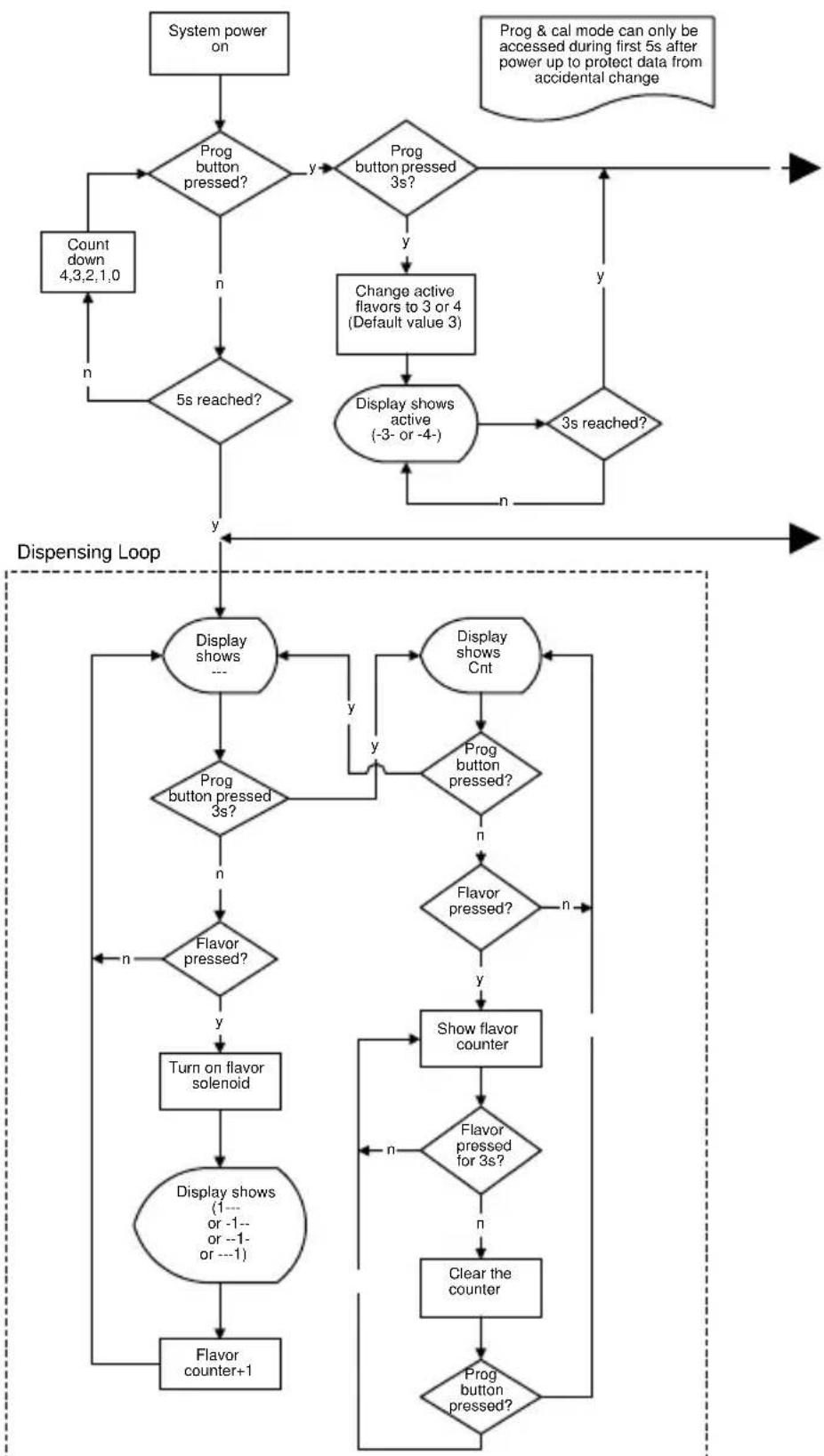
flowchart
graph TD
    A["System power on"] --> B{Prog button pressed?}
    B -->|y| C{Prog button pressed 3s?}
    C -->|y| D["Change active flavors to 3 or 4 (Default value 3)"]
    D --> E["Display shows active (-3- or -4-)"]
    E --> F{3s reached?}
    F -->|y| G["Prog & cal mode can only be accessed during first 5s after power up to protect data from accidental change"]
    G --> H["Count down 4,3,2,1,0"]
    H --> I{n}
    I --> J{5s reached?}
    J -->|y| K["Display shows active (-3- or -4-)"]
    K --> L["Display shows Cnt"]
    L --> M{Prog button pressed?}
    M -->|y| N["Flavor pressed?"]
    M -->|n| O["Display shows Cnt"]
    N --> P{Flavor pressed?}
    P -->|y| Q["Turn on flavor solenoid"]
    Q --> R["Display shows (1---or -1---or ---1)"]
    R --> S["Flavor counter+1"]
    S --> T["Display shows Cnt"]
    T --> U{Prog button pressed?}
    U -->|y| V["Display shows Cnt"]
    U -->|n| W["Show flavor counter"]
    W --> X{Flavor pressed for 3s?}
    X -->|y| Y["Clear the counter"]
    X -->|n| Z["Display shows Cnt"]
    Y --> AA["Display shows Cnt"]
    Z --> AB["Display shows Cnt"]
Programming Loop
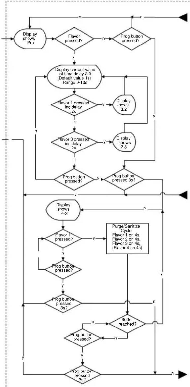
flowchart
graph TD
    A["Display shows Pro"] --> B{Flavor pressed?}
    B -->|y| C["Display current value of time delay 3.0 (Default value 1s) Range 0-10s"]
    B -->|n| D{Prog button pressed?}
    D -->|y| E["Display shows 3.2"]
    D -->|n| F["Display shows 2.8"]
    C --> G{Flavor 1 pressed inc delay .2s}
    G -->|y| H["Display shows 3.2"]
    G -->|n| I{Prog button pressed?}
    I -->|y| J{Prog button pressed 3s?}
    J -->|y| K["Display shows P-S"]
    J -->|n| L["Display shows P-S"]
    K --> M{Flavor 1 pressed?}
    M -->|y| N["Purge/Sanitize Cycle\nFlavor 1 on 4s,\nFlavor 2 on 4s,\nFlavor 3 on 4s,\n(Flavor 4 on 4s)"]
    M -->|n| O{Prog button pressed?}
    O -->|y| P{Prog button pressed 3s?}
    P -->|n| Q["900s reached?"]
    P -->|n| R["Prog button pressed?"]
    Q --> S{Prog button pressed?}
    S -->|n| T["Prog button pressed 3s?"]
    S -->|y| U["Prog button pressed 3s?"]
    T --> V["Prog button pressed 3s?"]
    U --> V
    V --> W["Prog button pressed 3s?"]
    W --> X["Display shows P-S"]
Programming Loop (continued on next page)
Programming Loop (continued from previous page)
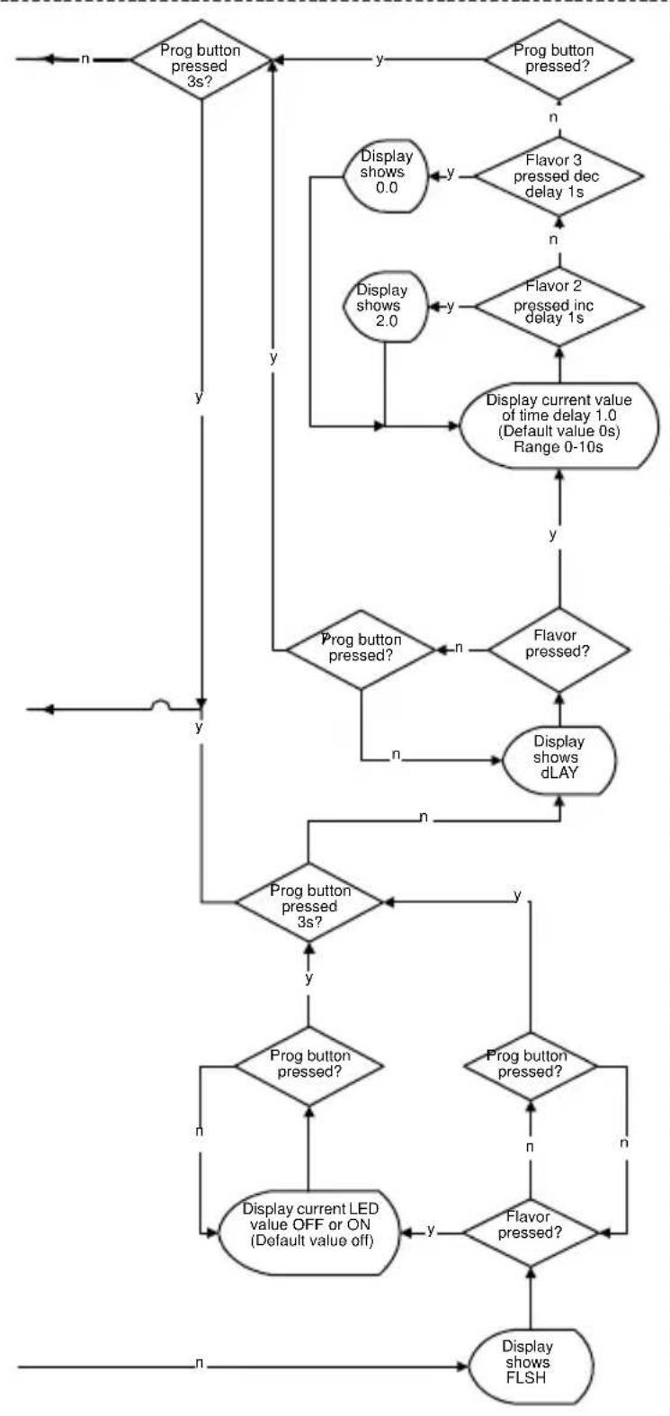
flowchart
graph TD
    A["Prog button pressed 3s?"] -->|y| B["Display shows 0.0"]
    A -->|y| C["Display shows 2.0"]
    B --> D{Flavor 3 pressed dec delay 1s}
    C --> E{Flavor 2 pressed inc delay 1s}
    D --> F["Display current value of time delay 1.0 (Default value 0s) Range 0-10s"]
    E --> F
    F --> G{Prog button pressed?}
    G -->|n| H["Display shows dLAY"]
    G -->|y| I{Prog button pressed 3s?}
    I -->|y| J["Display current LED value OFF or ON (Default value off)"]
    I -->|n| K["Display shows FLSH"]
    J --> L{Prog button pressed?}
    L -->|n| M["Display shows dLAY"]
    L -->|y| N["Display shows 2.0"]
    M --> O{Prog button pressed?}
    O -->|n| P["Display shows dLAY"]
    O -->|y| Q["Display shows FLSH"]
    P --> R{Prog button pressed?}
    R -->|n| S["Display shows dLAY"]
    R -->|y| T["Display shows FLSH"]
Flav'R-Pic (FRP-250) Logic Matrix
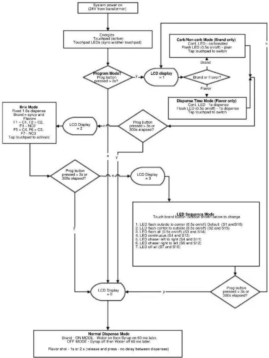
flowchart
graph TD
    A["System power on (24V from transformer)"] --> B["Energize Touchpad (active) Touchpad LEDs (sync w/other touchpad)"]
    B --> C{Program Mode? Prog button pressed >3s?}
    C -->|y| D["LCD display = 1"]
    D --> E{Brand or Flavor?}
    E -->|n| F["Carb/Non-carb Mode (Brand only) Cont. LED - carbonated Flash LED (0.5s on/off) - plain Tap touchpad to switch"]
    E -->|n| G["Dispense Time Mode (Flavor only) Cont. LED - 1s dispense Flash LED (0.5s on/off) - 1s dispense Tap touchpad to switch"]
    C --> H["LCD Display = 2"]
    H --> I{n}
    I -->|n| J{Prog button pressed >3s or 300s elapsed?}
    J -->|n| K["LCD Display = 3"]
    J -->|n| L["Brix Mode Fixed 1.6s dispense Brand = syrup and Flavor= F1 - C1, F2 - C2, F3 - NC2 F5 = C4, F6 = C3, F7 - NC3 Tap touchpad to activate"]
    J --> M{Prog button pressed >3s or 300s elapsed?}
    M -->|n| N["LCD Display = 0"]
    M -->|n| O["LED Sequence Mode Touch brand button location shown below to change"]
    O --> P{Prog button pressed >3s or 300s elapsed?}
    P -->|y| Q["Normal Dispense Mode Brand - ON MODE - Water on then Syrup on 60 ms later. OFF MODE - Syrup off then Water off 60 ms later. Flavor shot - 1s or 2 s (release and press - no delay between dispenses)"]
    P --> R["End"]
FLAV'R-PIC (FRP-250) CONTROL BOARD, VALVE, TOUCH PAD MATRIX
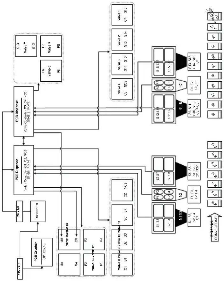
flowchart
graph TD
    A["PCB Disperse"] --> B["Valve Controls - C1, C2, NC2"]
    A --> C["Valve Controls - S1-S8, F1-F4"]
    A --> D["Valve 15Valve 14"]
    A --> E["Valve 13 Valve 12"]
    A --> F["Valve 8 Valve 9 Valve 10 Valve 11"]
    A --> G["Valve 6"]
    A --> H["Valve 5"]
    A --> I["Valve 7"]
    A --> J["Valve 6"]
    A --> K["Valve 5"]
    A --> L["Valve 4"]
    A --> M["Valve 3"]
    A --> N["Valve 2"]
    A --> O["Valve 1"]
    A --> P["Valve 15"]
    A --> Q["Valve 9"]
    A --> R["Valve 13"]
    A --> S["Valve 8"]
    A --> T["Valve 6"]
    A --> U["Valve 5"]
    A --> V["Valve 4"]
    A --> W["Valve 3"]
    A --> X["Valve 2"]
    A --> Y["Valve 15"]
    A --> Z["Valve 9"]
    A --> AA["Valve 13"]
    A --> AB["Valve 8"]
    A --> AC["Valve 6"]
    A --> AD["Valve 5"]
    A --> AE["Valve 4"]
    A --> AF["Valve 3"]
    A --> AG["Valve 2"]
    A --> AH["Valve 15"]
    A --> AI["Valve 9"]
    A --> AJ["Valve 13"]
    A --> AK["Valve 8"]
    A --> AL["Valve 6"]
    A --> AM["Valve 5"]
    A --> AN["Valve 4"]
    A --> AO["Valve 3"]
    A --> AP["Valve 2"]
    A --> AQ["Valve 15"]
    A --> AR["Valve 9"]
    A --> AS["Valve 13"]
    A --> AT["Valve 8"]
    A --> AU["Valve 6"]
    A --> AV["Valve 5"]
    A --> AW["Valve 4"]
    A --> AX["Valve 3"]
    A --> AY["Valve 2"]
    A --> AZ["Valve 15"]
    A --> BA["Valve 9"]
    A --> BB["Valve 13"]
    A --> BC["Valve 8"]
    A --> BD["Valve 6"]
    A --> BE["Valve 5"]
    A --> BF["Valve 4"]
    A --> BG["Valve 3"]
    A --> BH["Valve 2"]
    A --> BI["Valve 15"]
    A --> BJ["Valve 9"]
    A --> BK["Valve 13"]
    A --> BL["Valve 8"]
    A --> BM["Valve 6"]
    A --> BN["Valve 5"]
    A --> BO["Valve 4"]
    A --> BP["Valve 3"]
    A --> BQ["Valve 2"]
    A --> BR["Valve 15"]
This Page Intentionally Left Blank
Diagrams
Blade Tower Plumbing
SINGLE TOWER
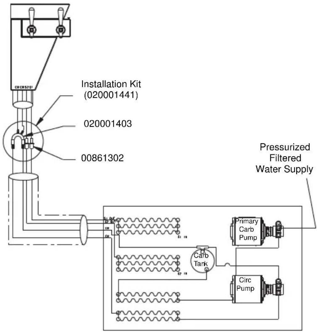
flowchart
graph TD
    A["Pressurized Filtered Water Supply"] --> B["Installation Kit (020001441)"]
    B --> C["Carb Tank"]
    C --> D["Circ Pump"]
    D --> E["Primary Carb Pump"]
    E --> F["Carb Tank"]
    F --> G["020001403"]
    G --> H["00861302"]
    H --> I["020001441"]
TWO TOWER
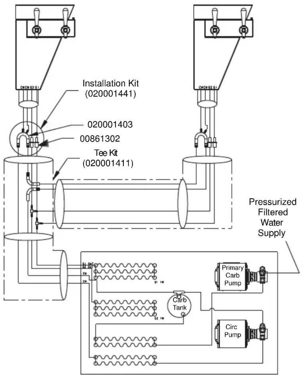
flowchart
graph TD
    A["Installation Kit (020001441)"] --> B["Tee Kit (020001411)"]
    C["020001403"] --> B
    D["00861302"] --> B
    E["Primary Carb Pump"] --> F["Circ Pump"]
    G["Carb Tank"] --> F
    H["Pressurized Filtered Water Supply"] --> F
    style A fill:#f9f,stroke:#333
    style C fill:#f9f,stroke:#333
    style D fill:#f9f,stroke:#333
    style E fill:#f9f,stroke:#333
    style F fill:#ccf,stroke:#333
    style G fill:#ccf,stroke:#333
    style H fill:#ccf,stroke:#333
THREE TOWER
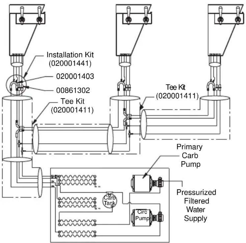
flowchart
graph TD
    A["Installation Kit (020001441)"] --> B["Tee Kit (020001411)"]
    C["020001403"] --> B
    D["00861302"] --> B
    E["Tee Kit (020001411)"] --> B
    B --> F["Primary Carb Pump"]
    B --> G["Pressurized Filtered Water Supply"]
    H["Carb Tank"] --> I["Circ Pump"]
    I --> B
CEV-30i & CEV-30e Plumbing
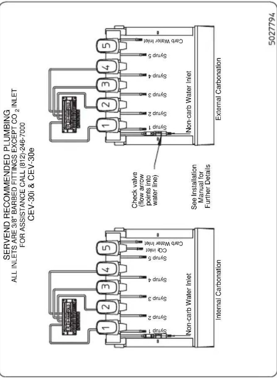
NOTE:
- All valves are carbonated water as shipped from factory.
- Check valve supplied with unit is installed in the non-carbonated water line inlet. The flow direction arrow should point into the stainless steel line.
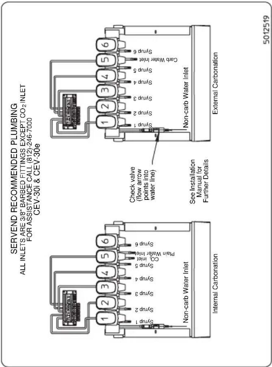
NOTE:
- All valves are carbonated water as shipped from factory.
- Check valve supplied with unit is installed in the non-carbonated water line inlet. The flow direction arrow should point into the stainless steel line.
CEV-40i & CEV-40e Plumbing
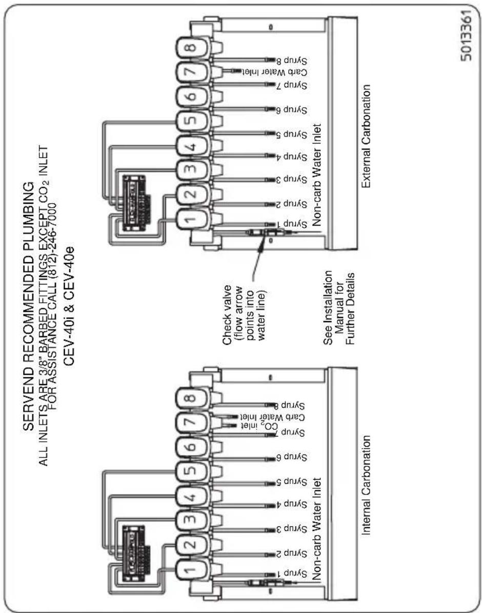
NOTE:
- All valves are carbonated water as shipped from factory.
- Check valve supplied with unit is installed in the non-carbonated water line inlet. The flow direction arrow should point into the stainless steel line.
CEV-30j Plumbing
![SERVEND RECOMMENDED PLUMBING ALL INLETS ARE 3/8" BARBED FITTINGS FOR ASSISTANCE CALL (812)-246-7000 CEV-30] 1 2 3 4 5 6 Syrp 1 Syrp 2 Syrp 3 Syrp 4 Plain Water Inlet Syrp 5 Syrp 6 6 Valve Inlet 5 Valve Inlet 1 2 3 4 5 Syrp 1 Syrp 2 Syrp 3 Syrp 4 Plain Water Inlet Syrp 5 Plain Water Inlet Syrp 6 Plain Water Inlet Syrp 7 Plain Water Inlet Syrp 8 Plain Water Inlet Syrp 9 Plain Water Inlet Syrp 10 Plain Water Inlet Syrp 11 Plain Water Inlet Syrp 12 Plain Water Inlet Syrp 13 Plain Water Inlet Syrp 14 Plain Water Inlet Syrp 15 Plain Water Inlet Syrp 16 Plain Water Inlet Syrp 17 Plain Water Inlet Syrp 18 Plain Water Inlet Syrp 19 Plain Water Inlet Syrp 20 Plain Water Inlet Syrp 21 Plain Water Inlet Syrp 22 Plain Water Inlet Syrp 23 Plain Water Inlet Syrp 24 Plain Water Inlet Syrp 25 Plain Water Inlet Syrp 26 Plain Water Inlet Syrp 27 Plain Water Inlet Syrp 28 Plain Water Inlet Syrp 29 Plain Water Inlet Syrp 30 Plain Water Inlet Syrp 31 Plain Water Inlet Syrp 32 Plain Water Inlet Syrp 33 Plain Water Inlet Syrp 34](/content/2026/05/935851/images/7cc6e0822d8fda22f849d588818698ca396413bb44b96b0d44adfc8b861bd4b8.jpg)
NOTE:
- Minimum water pressure of 40 psi is needed to attain a 1-1/2 oz/sec flow rate.
- Minimum water pressure of 55 psi is needed to attain a 2-1/2 oz/sec flow rate.
- If water pressure varies by ±20 psi the valve brix will not be maintained.
- See service manual for further details.
CT-6 Plumbing and Wiring
| CAUTION Electrical Shock Hazard Disconnect power before servicing. | 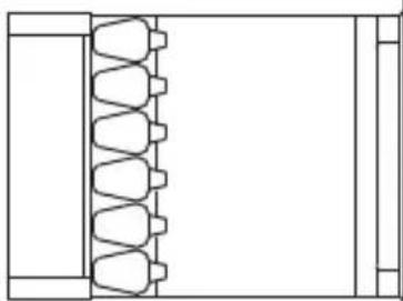 | 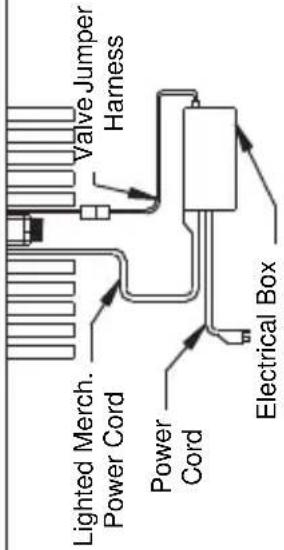 |
| CT-6 Wiring Diagram | ||
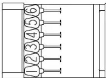 |  | |
CT-8 Plumbing and Wiring
| CAUTION Electrical Shock Hazard Disconnect power before servicing. | 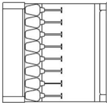 | Valve Jumper Harness Electrical Box Lighted Merch. Power Cord Power Cord |
| CT-8 Wiring Diagram | ||
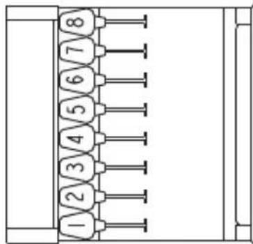 | ||
| SYRIP 1 Syrp 2 Syrp 3 Syrp 4 Syrp 5 Syrp 6 Syrp 7 Syrp 8 Unit Drain Counter Top | ||
CF-1522 Plumbing
CF-1522 4 Valve Plumbing
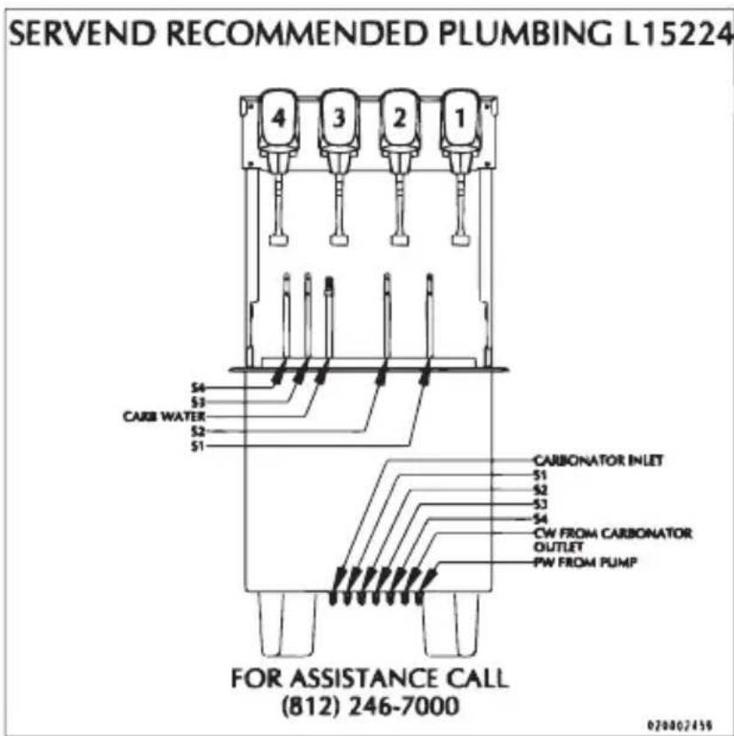
Conversion for non-carbonated flavor
- De-pressurize system.
- Remove drain grid, splash panel and drainpan to access insulated lines.
- Cut carb water line (in tower) to valve to be converted and cap.
- Disconnect syrup line to valve being converted.
- Plumb syrup circuit in coldplate to water side of valve (flush syrup line first).
- Plumb dedicated plain water line from water source to coldplate inlet (syrup circuit converted for chilling water).
- Run ambient syrup line into drop-in tower to syrup side of valve.
- Replace drainpan, splash panel and drain grid.
- Pressurize system and verify system operation.
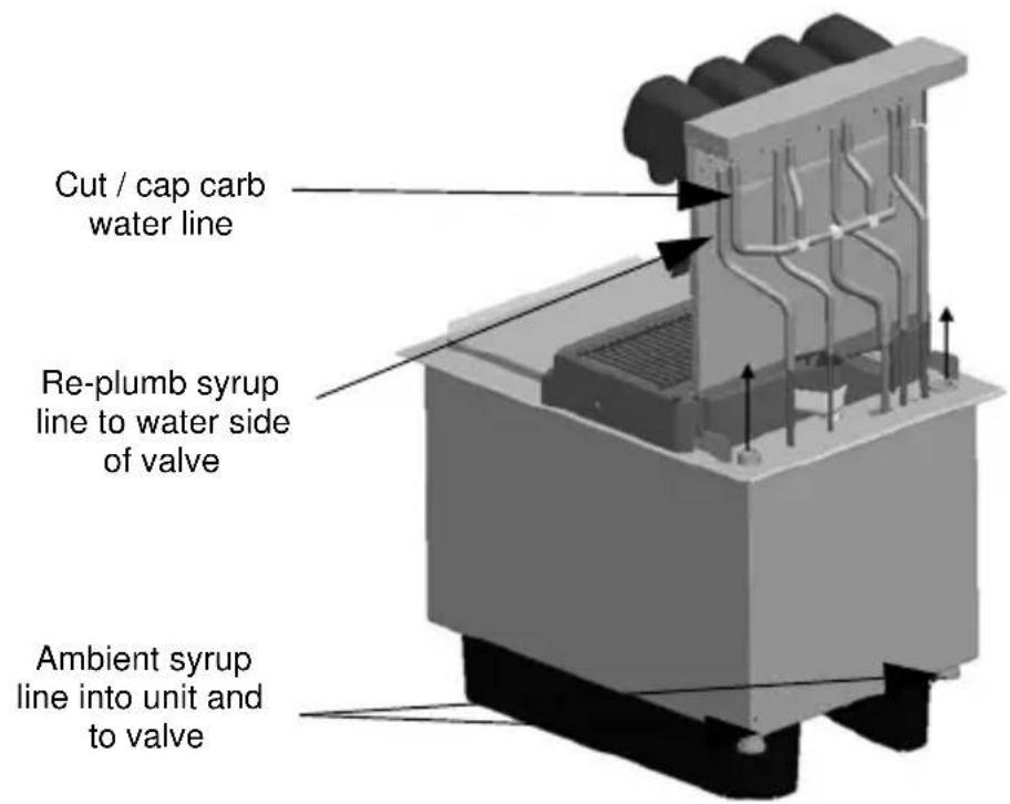
NOTE: Tapping into existing water line too close to the pump deck can result in starving the valve when the carbonator cycles. If a dedicated water line is not possible, tee into the existing water line as close to the source as possible.
DI-1522 Post-mix Plumbing
SERVEND RECOMMENDED PLUMBING: DI-1522 IC
2-1-1-2 Right to Left
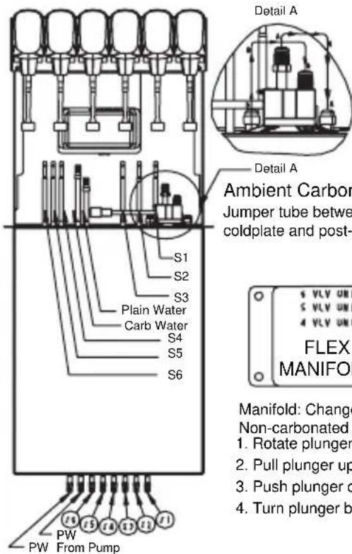
NOTE 1:
A. Plain water to the carbonator
B. Carb water to coldplate post-chill
NOTE 2:
For 5(4) vale unit:
- Inlet syrup number 6(6.5) isn't used
- Valve number 6(6.5) isn't used
Ambient Carbonation
Jumper tube between pre-chill
coldplate and post-chill in coldplate
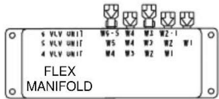
Manifold: Change to Carbonated or
Non-carbonated water
- Rotate plunger 180° using a 5/32" allen wrench.
- Pull plunger up to get non-carbonated water.
- Push plunger down to get carb. water.
- Turn plunger back 180° to lock.
For Assistance Call
812-246-7000
5029044-
DI-1522 Pre-mix Plumbing
SERVEND RECOMMENDED PLUMBING: DI-1522 PREMIX
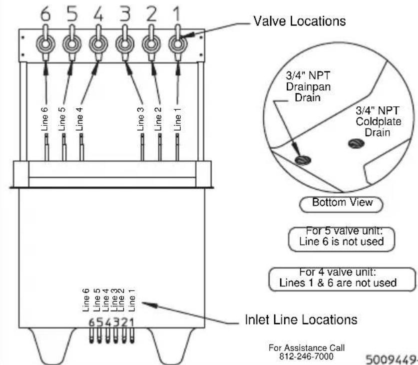
DI/DIL-2323 6 Valve Post-mix Plumbing
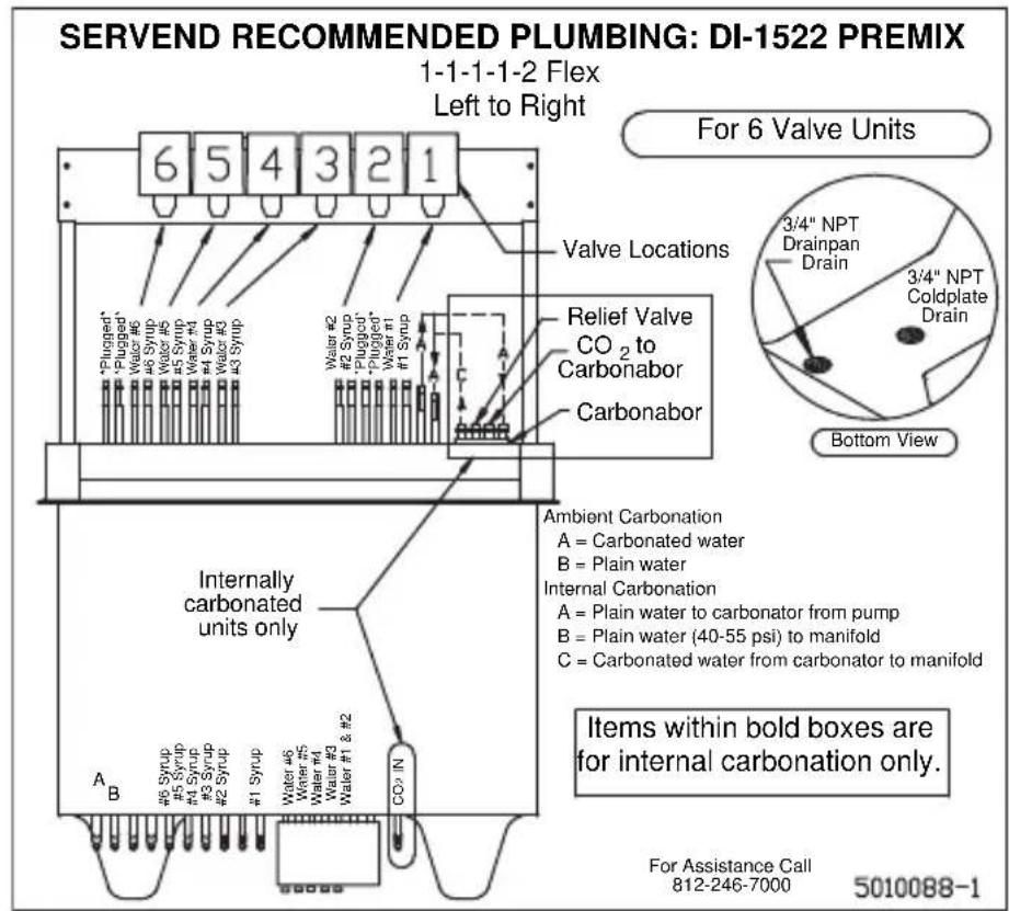
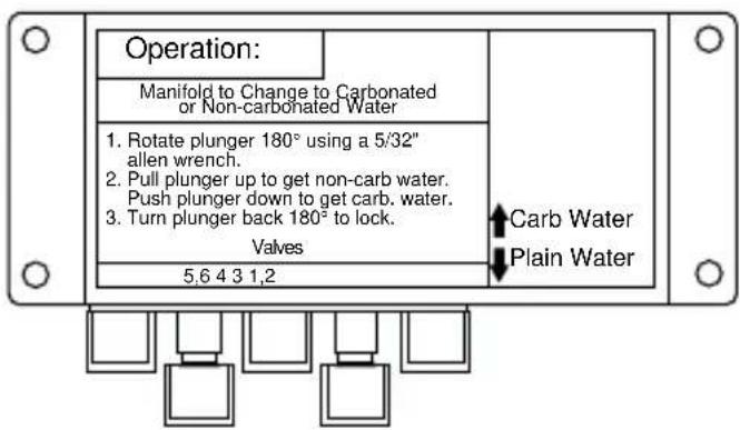
DI/DIL-2323 8 Valve Post-mix Plumbing & Variety Valve
SERVEND RECOMMENDED PLUMBING: DI/DIL-2323
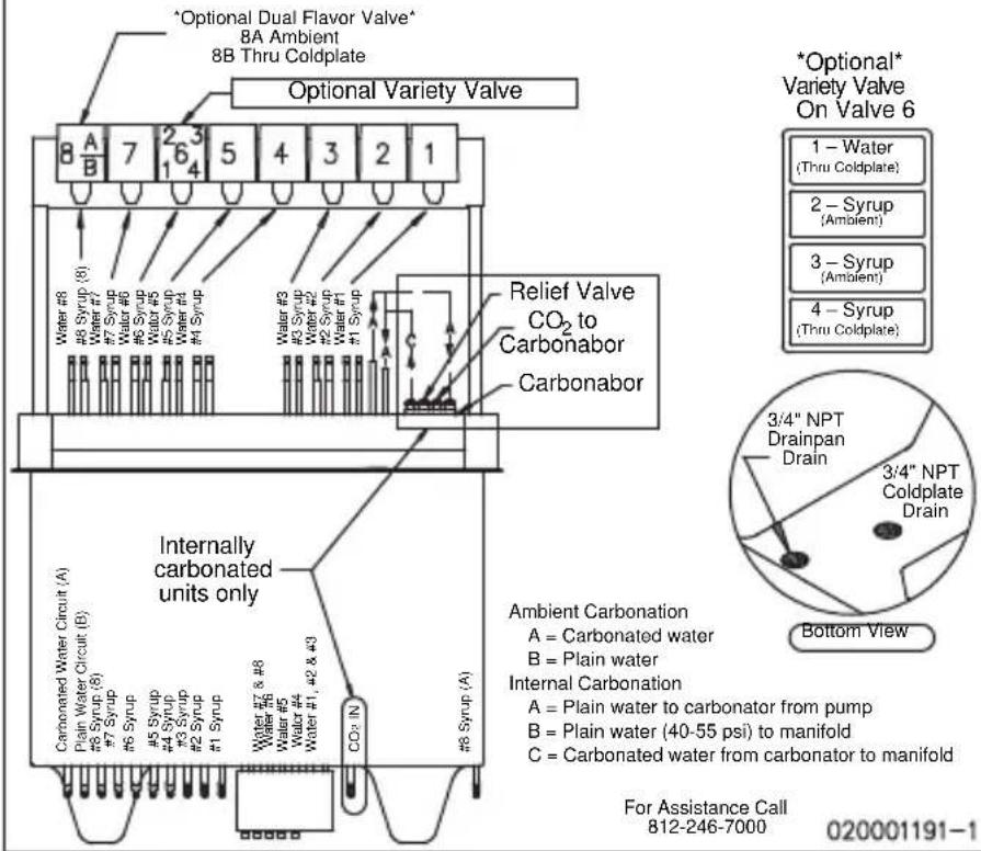
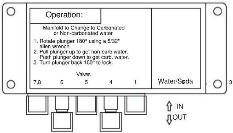
DI/DIL-2323 10 Valve Post-mix Plumbing
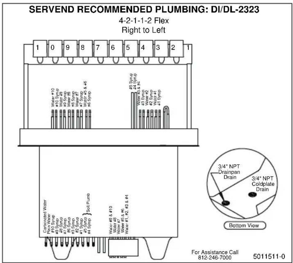
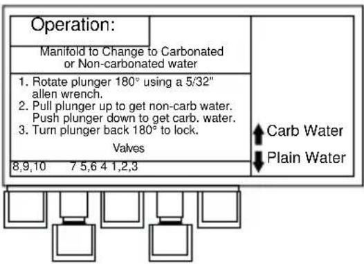
DI/DIL-2323 6 Valve Pre-mix Plumbing
SERVEND RECOMMENDED PLUMBING: DI/DL-2323
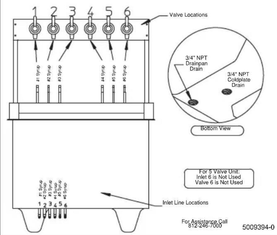
Flavor Magic Plumbing
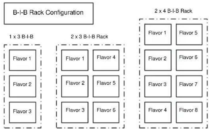
flowchart
graph TD
    A["B-I-B Rack Configuration"] --> B["1 x 3 B-I-B"]
    A --> C["2 x 3 B-I-B Rack"]
    A --> D["2 x 4 B-I-B Rack"]

    B --> E["Flavor 1"]
    B --> F["Flavor 2"]
    B --> G["Flavor 3"]

    C --> H["Flavor 1"]
    C --> I["Flavor 4"]
    C --> J["Flavor 2"]
    C --> K["Flavor 5"]
    C --> L["Flavor 3"]
    C --> M["Flavor 6"]

    D --> N["Flavor 1"]
    D --> O["Flavor 5"]
    D --> P["Flavor 2"]
    D --> Q["Flavor 6"]
    D --> R["Flavor 3"]
    D --> S["Flavor 7"]
    D --> T["Flavor 4"]
    D --> U["Flavor 8"]
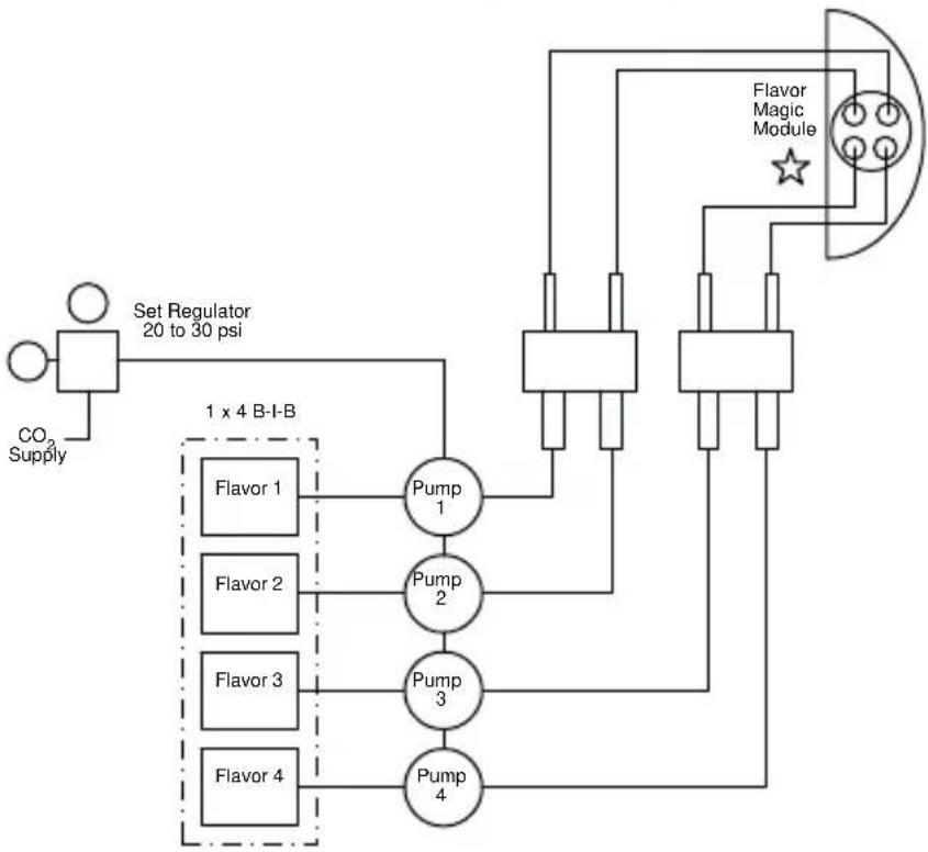
flowchart
graph TD
    A["CO2 Supply"] --> B["Set Regulator 20 to 30 psi"]
    B --> C["Pump 1"]
    B --> D["Pump 2"]
    B --> E["Pump 3"]
    B --> F["Pump 4"]
    C --> G["Flavor 1"]
    C --> H["Flavor 2"]
    C --> I["Flavor 3"]
    C --> J["Flavor 4"]
    D --> K["Flavor Magic Module"]
    E --> K
    F --> K
    K --> L["Output"]
    style A fill:#fff,stroke:#000
    style B fill:#fff,stroke:#000
    style C fill:#fff,stroke:#000
    style D fill:#fff,stroke:#000
    style E fill:#fff,stroke:#000
    style F fill:#fff,stroke:#000
    style G fill:#fff,stroke:#000
    style H fill:#fff,stroke:#000
    style I fill:#fff,stroke:#000
    style J fill:#fff,stroke:#000
    style K fill:#fff,stroke:#000
FRP-250 Plumbing Diagram
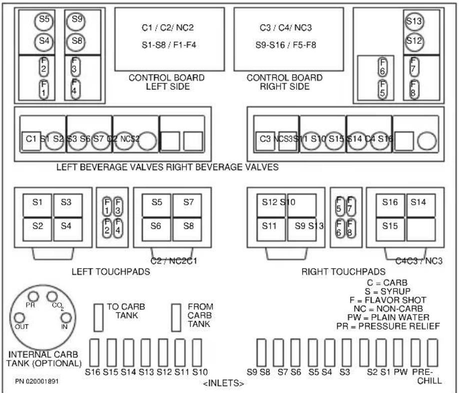
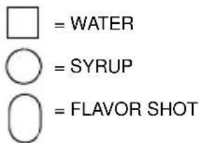
FRP-250 & FRP-250SCI Tubing Layout
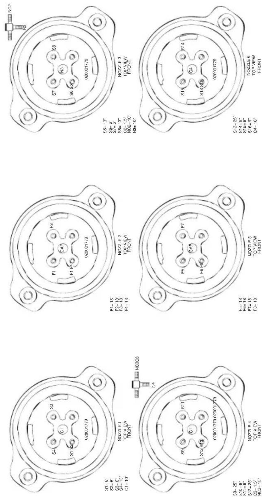
FT-8 Plumbing
FT-8
Recommended Plumbing
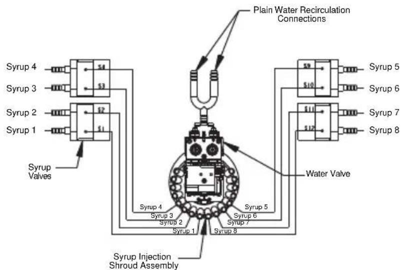
flowchart
graph TD
    A["Syrup 1"] --> B["Syrup 2"]
    B --> C["Syrup 3"]
    C --> D["Syrup 4"]
    D --> E["Syrup 5"]
    E --> F["Syrup 6"]
    F --> G["Syrup 7"]
    G --> H["Syrup 8"]
    H --> I["Water Valve"]
    I --> J["Plain Water Recirculation Connections"]
    K["Syrup Valves"] --> L["Syrup Injection Shroud Assembly"]
    M["Syrup 1"] --> N["Syrup 2"]
    O["Syrup 3"] --> P["Syrup 4"]
    Q["Syrup 4"] --> R["Syrup 5"]
    S["Syrup 5"] --> T["Syrup 6"]
    U["Syrup 6"] --> V["Syrup 7"]
    W["Syrup 7"] --> X["Syrup 8"]
Part No. 020000893 Revision No. 0
FT-12 Plumbing
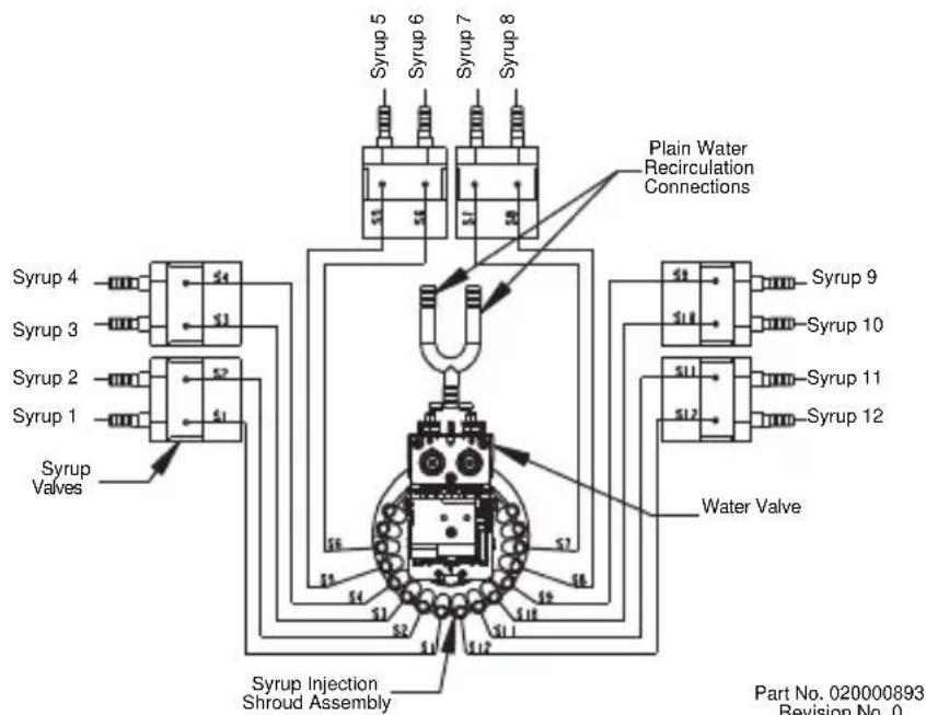
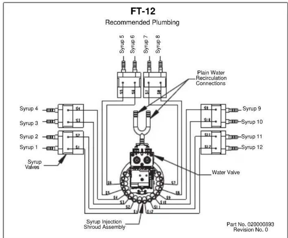
flowchart
graph TD
    A["Compressor"] --> B["Syrup 1"]
    A --> C["Syrup 2"]
    A --> D["Syrup 3"]
    A --> E["Syrup 4"]
    A --> F["Syrup 5"]
    A --> G["Syrup 6"]
    A --> H["Syrup 7"]
    A --> I["Syrup 8"]
    A --> J["Water Valve"]
    A --> K["Plain Water Recirculation Connections"]
    A --> L["Syrup Injection Shroud Assembly"]
    A --> M["Part No. 020000893 Revision No. 0"]
FlexTower Water Recirculation Pump Flow
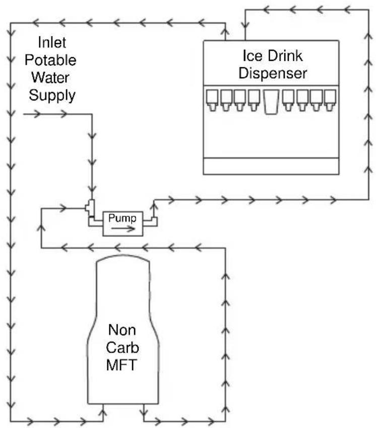
flowchart
graph TD
    A["Inlet Potable Water Supply"] --> B["Pump"]
    B --> C["Non Carb MFT"]
    C --> D["Ice Drink Dispenser"]
    D --> E["Output"]
    B --> F["Feedback Loop"]
    F --> A
FlexTower Water Chiller Flow
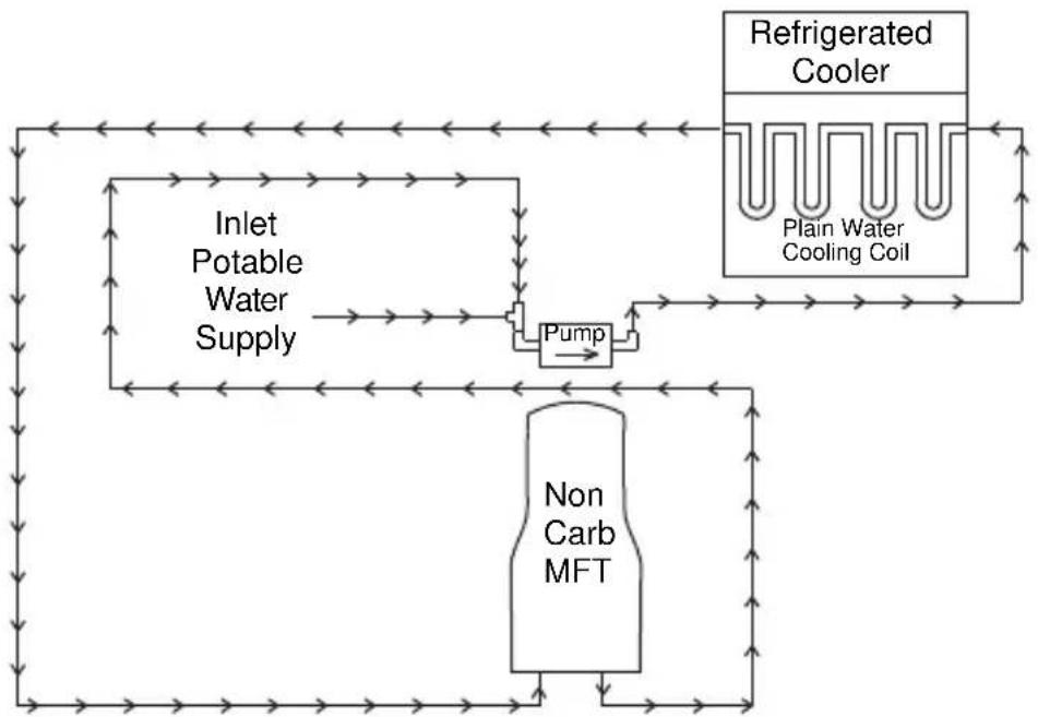
flowchart
graph TD
    A["Inlet Potable Water Supply"] --> B["Pump"]
    B --> C["Non Carb MFT"]
    D["Refrigerated Cooler"] --> E["Plain Water Cooling Coil"]
    E --> B
MDH-302 12 Valve Plumbing
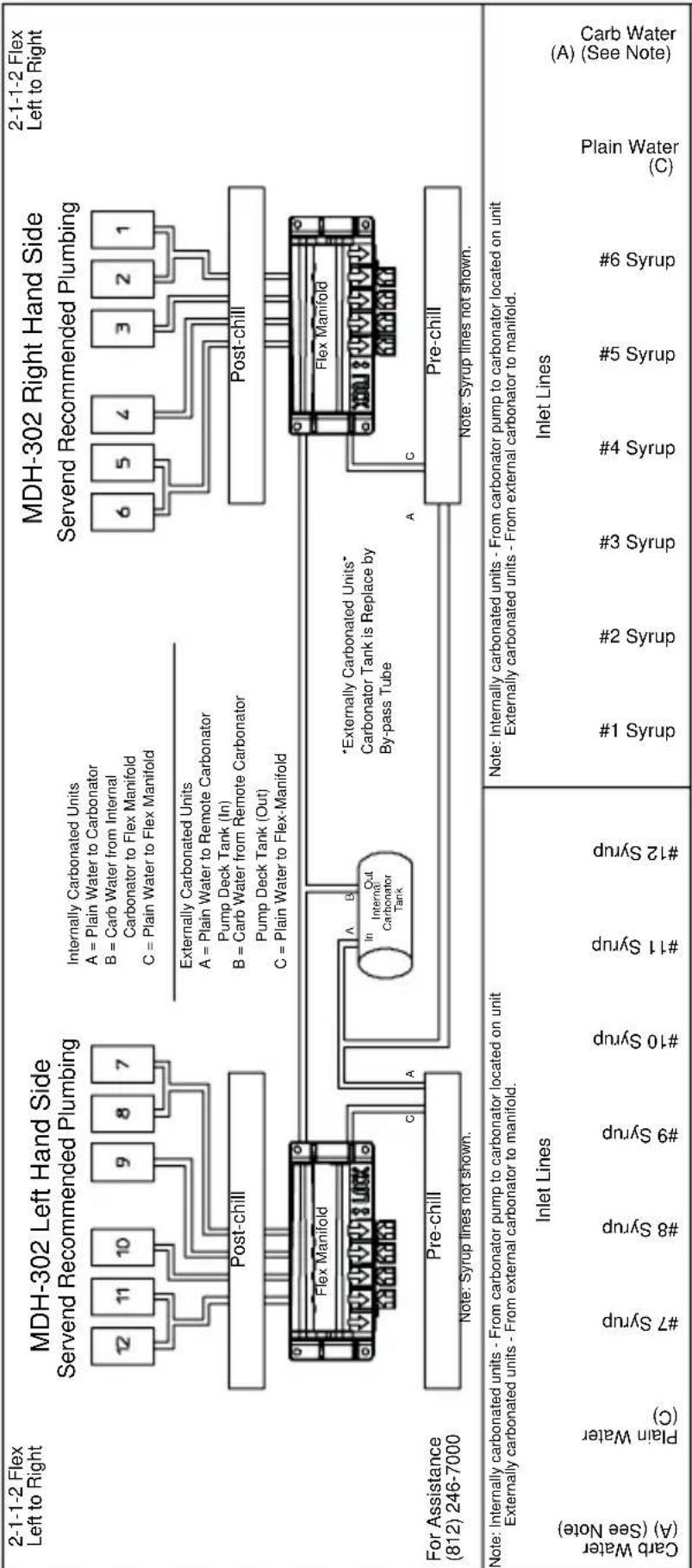
flowchart
graph TD
    subgraph MDH-302 Right Hand Side
        A["MDH-302 Left Hand Side Servend Recommended Plumbing"] --> B["Post-chill"]
        B --> C["Pre-chill"]
        C --> D["For Assistance (812) 246-7000"]
    end

    subgraph MDH-302 Left Side
        E["MDH-302 Right Hand Side Servend Recommended Plumbing"] --> F["Post-chill"]
        F --> G["Pre-chill"]
        G --> H["For Assistance (812) 246-7000"]

    I["Carb Water (A) (See Note)"] --> J["Plain Water (C)"]
    J --> K["#7 Syrup"]
    K --> L["#8 Syrup"]
    L --> M["#9 Syrup"]
    M --> N["#10 Syrup"]
    N --> O["#11 Syrup"]
    O --> P["#12 Syrup"]

    Q["Carb Water (A) (See Note)"] --> R["Plain Water (C)"]
    R --> S["#7 Syrup"]
    S --> T["#8 Syrup"]
    T --> U["#9 Syrup"]
    U --> V["#10 Syrup"]
    V --> W["#11 Syrup"]
    W --> X["#12 Syrup"]

    Y["Carb Water (A) (See Note)"] --> Z["Plain Water (C)"]
    Z --> AA["#7 Syrup"]
    AA --> AB["#8 Syrup"]
    AB --> AC["#9 Syrup"]
    AC --> AD["#10 Syrup"]
    AD --> AE["#11 Syrup"]
    AE --> AF["#12 Syrup"]

    AG["Carb Water (A) (See Note)"] --> AH["Plain Water (C)"]
    AH --> AI["#7 Syrup"]
    AI --> AJ["#8 Syrup"]
    AJ --> AK["#9 Syrup"]
    AK --> AL["#10 Syrup"]
    AL --> AM["#11 Syrup"]
    AM --> AN["#12 Syrup"]

    AO["Carb Water (A) (See Note)"] --> AP["Plain Water (C)"]
    AP --> AQ["#7 Syrup"]
    AQ --> AR["#8 Syrup"]
    AR --> AS["#9 Syrup"]
    AS --> AT["#10 Syrup"]
    AT --> AU["#11 Syrup"]
    AU --> AV["#12 Syrup"]

    AW["Carb Water (A) (See Note)"] --> AX["Plain Water (C)"]
    AX --> AY["#7 Syrup"]
    AY --> AZ["#8 Syrup"]
    AZ --> BA["#9 Syrup"]
    BA --> BB["#10 Syrup"]
    BB --> BC["#11 Syrup"]
    BC --> BD["#12 Syrup"]

    BE["Carb Water (A) (See Note)"] --> BF["Plain Water (C)"]
    BF --> BG["#7 Syrup"]
    BG --> BH["#8 Syrup"]
    BH --> BI["#9 Syrup"]
    BI --> BJ["#10 Syrup"]
    BJ --> BK["#11 Syrup"]
    BK --> BL["#12 Syrup"]

    BM["Carb Water (A) (See Note)"] --> BN["Plain Water (C)"]
    BN --> BO["#7 Syrup"]
    BO --> BP["#8 Syrup"]
    BP --> BQ["#9 Syrup"]
    BQ --> BR["#10 Syrup"]
    BR --> BS["#11 Syrup"]
    BS --> BT["#12 Syrup"]

    BU["Carb Water (A) (See Note)"] --> BV["Plain Water (C)"]
    BV --> BW["#7 Syrup"]
    BW --> BX["#8 Syrup"]
    BX --> BY["#9 Syrup"]
    BY --> BZ["#10 Syrup"]
    BZ --> CA["#11 Syrup"]
    CA --> CB["#12 Syrup"]

    CC["Carb Water (A) (See Note)"] --> DD["Plain Water (C)"]
    DD --> DE["#7 Syrup"]
    DE --> DF["#8 Syrup"]
    DF --> DG["#9 Syrup"]
    DG --> DH["#10 Syrup"]
    DH --> DI["#11 Syrup"]
    DI --> DJ["#12 Syrup"]

    CE["Carb Water (A) (See Note)"] --> CF["Plain Water (C)"]
    CF --> CG["#7 Syrup"]
    CG --> DHG["#8 Syrup"]
    DHG --> DHX["#9 Syrup"]
    DHX --> DHZ["#10 Syrup"]
    DHZ --> DHX["#11 Syrup"]
    DHX --> DHXG["#12 Syrup"]

    CE --> DHX
    DHX --> DHXG
    DHXG --> DHXZ
MDH-402 16 Valve Plumbing
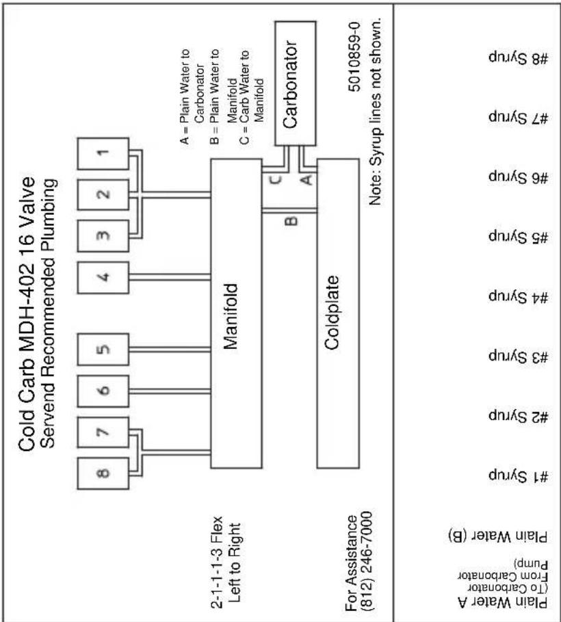
flowchart
graph TD
    A["Plain Water A (To Carbonator From Carbonator Pump)"] --> B["Plain Water (B)"]
    B --> C["#1 Syrup"]
    B --> D["#2 Syrup"]
    B --> E["#3 Syrup"]
    B --> F["#4 Syrup"]
    B --> G["#5 Syrup"]
    B --> H["#6 Syrup"]
    B --> I["#7 Syrup"]
    B --> J["#8 Syrup"]
    K["2-1-1-1-3 Flex Left to Right"] --> L["Manifold"]
    M["Coldplate"] --> N["Carbonator"]
    O["A = Plain Water to Carbonator\nB = Plain Water to Manifold\nC = Carb Water to Manifold"] --> P["B"]
    P --> Q["C"]
    Q --> R["A"]
    R --> S["Note: Syrup lines not shown."]
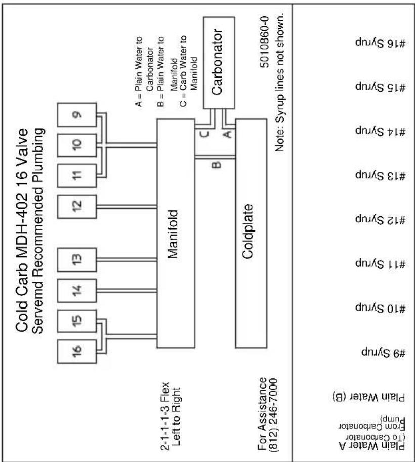
flowchart
graph TD
    A["Cold Carb MDH-402 16 Valve Servemd Recommended Plumbing"] --> B["Manifold"]
    B --> C["Coldplate"]
    C --> D["Carbonator"]
    style A fill:#f9f,stroke:#333
    style B fill:#ccf,stroke:#333
    style C fill:#cfc,stroke:#333
    style D fill:#fcc,stroke:#333
MDH-402 20 Valve Plumbing
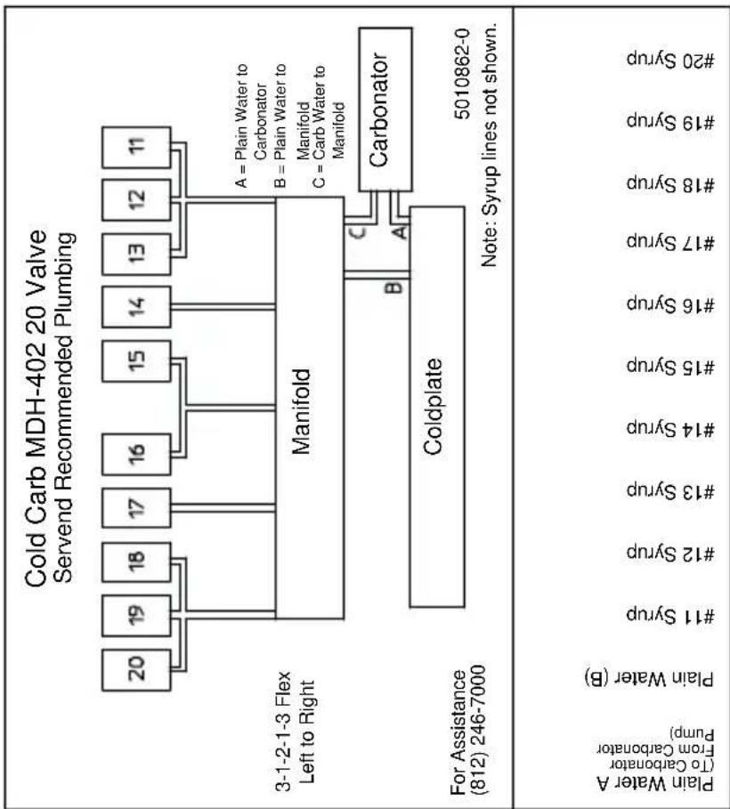
flowchart
graph TD
    A["Cold Carb MDH-402 20 Valve Servend Recommended Plumbing"] --> B["Manifold"]
    B --> C["Coldplate"]
    C --> D["Carbonator"]
    D --> E["3-1-2-1-3 Flex Left to Right"]
    D --> F["For Assistance (812) 246-7000"]
    B --> G["A = Plain Water to Carbonator\nB = Plain Water to Manifold\nC = Carb Water to Manifold"]
    C --> H["Note: Syrup lines not shown."]
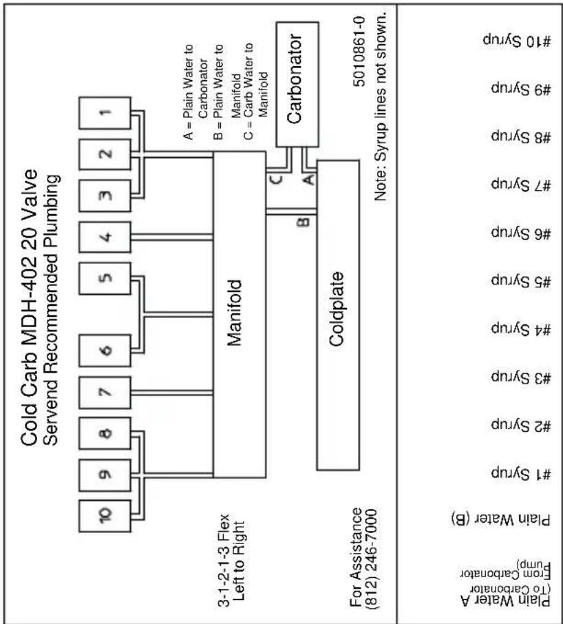
flowchart
graph TD
    A["Cold Carb MDH-402 20 Valve Servend Recommended Plumbing"] --> B["Manifold"]
    B --> C["Carbonator"]
    B --> D["Coldplate"]
    D --> E["3-1-2-1-3 Flex Left to Right"]
    D --> F["For Assistance (812) 246-7000"]
    B --> G["A = Plain Water to Carbonator\nB = Plain Water to Manifold\nC = Carb Water to Manifold"]
    D --> H["Note: Syrup lines not shown."]
S/SV150 6 Valve Diagram
PLUMBING: 2-1-1-2 MANIFOLDING
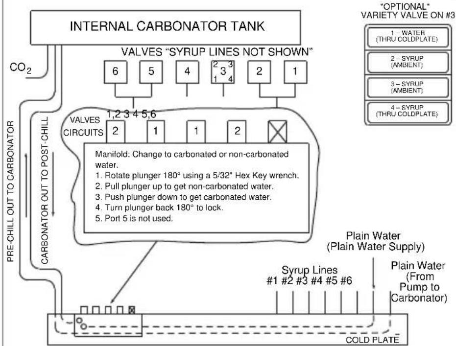
flowchart
graph TD
    A["INTERNAL CARBONATOR TANK"] --> B["VALVES "SYRUP LINES NOT SHOWN""]
    B --> C["VALVES CIRCUITS"]
    C --> D["PRE-CHILL OUT TO CARBONATOR"]
    C --> E["CARBONATOR OUT TO POST-CHILL"]
    D --> F["CO2"]
    E --> G["CO2"]
    F --> H["6"]
    F --> I["5"]
    F --> J["4"]
    F --> K["2 3 4"]
    F --> L["2"]
    F --> M["1"]
    G --> N["2"]
    G --> O["1"]
    G --> P["1"]
    G --> Q["2"]
    H --> R["Manifold: Change to carbonated or non-carbonated water."]
    I --> R
    J --> R
    K --> R
    L --> R
    M --> R
    N --> S["1,2 3 4 5,6"]
    O --> S
    P --> S
    Q --> S
    R --> T["1 - WATER (THRU COLDPLATE)"]
    R --> U["2 - SYRUP (AMBIENT)"]
    R --> V["3 - SYRUP (AMBIENT)"]
    R --> W["4 - SYRUP (THRU COLDPLATE)"]
    S --> X["Syrup Lines #1 #2 #3 #4 #5 #6"]
    T --> Y["Plain Water (Plain Water Supply)"]
    U --> Y
    V --> Y
    W --> Y
    X --> Z["COLD PLATE"]
    Y --> AA["Plain Water (From Pump to Carbonator)"]
* EXTERNALLY CARBONATED UNITS: CARBONATOR IS REPLACED BY BY-PASS TUBE FOR ASSISTANCE CALL (812) 246-7000
S/SV175 8 Valve Diagram
PLUMBING: 3-1-1-1-2 MANIFOLDING
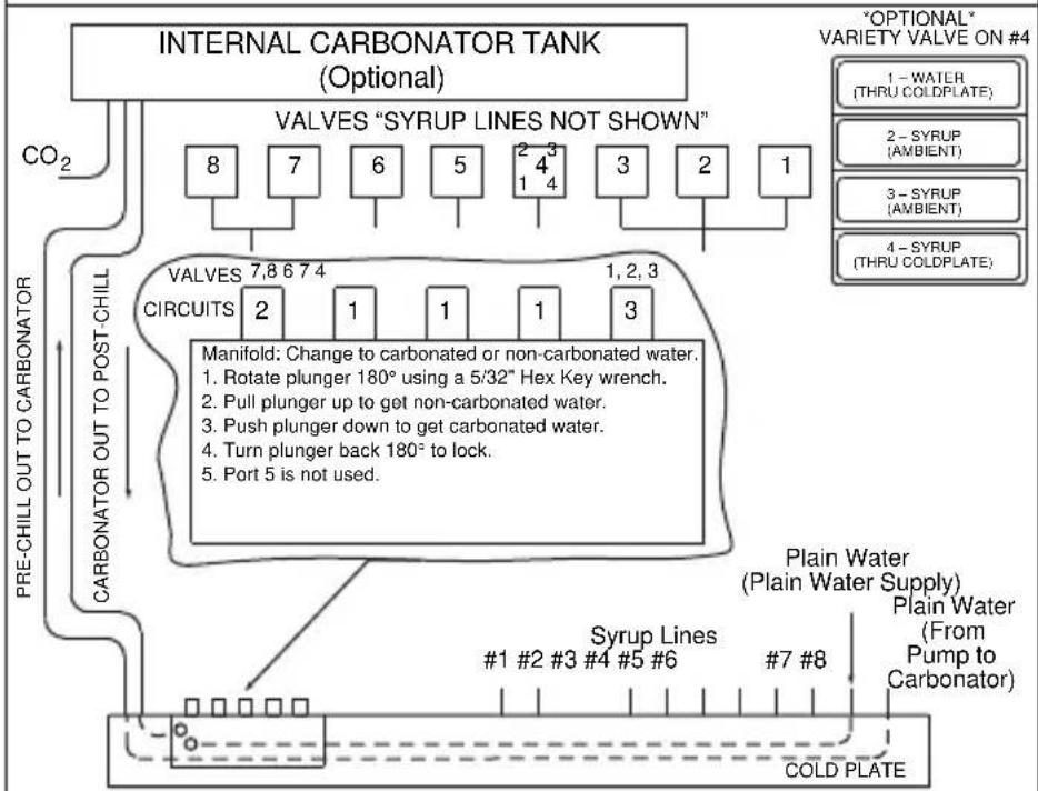
flowchart
graph TD
    A["INTERNAL CARBONATOR TANK (Optional)"] --> B["VALVES "SYRUP LINES NOT SHOWN""]
    B --> C["8"]
    B --> D["7"]
    B --> E["6"]
    B --> F["5"]
    B --> G["2 4 3 1 4"]
    B --> H["3"]
    B --> I["2"]
    B --> J["1"]
    K["CARBONATOR OUT TO POST-CHILL"] --> L["CARBONATOR OUT TO POST-CHILL"]
    L --> M["VALVES 7,8 6 7 4"]
    L --> N["CIRCUITS 2"]
    L --> O["Manifold: Change to carbonated or non-carbonated water."]
    O --> P["1. Rotate plunger 180° using a 5/32" Hex Key wrench."]
    O --> Q["2. Pull plunger up to get non-carbonated water."]
    O --> R["3. Push plunger down to get carbonated water."]
    O --> S["4. Turn plunger back 180° to lock."]
    O --> T["5. Port 5 is not used."]
    U["COLD PLATE"] --> V["Syrup Lines #1 #2 #3 #4 #5 #6"]
    U --> W["#7 #8"]
    X["“OPTIONAL” VARIETY VALVE ON #4"] --> Y["1 - WATER (THRU COLDPLATE)"]
    X --> Z["2 - SYRUP (AMBIENT)"]
    X --> AA["3 - SYRUP (AMBIENT)"]
    X --> AB["4 - SYRUP (THRU COLDPLATE)"]
* EXTERNALLY CARBONATED UNITS: CARBONATOR IS REPLACED BY BY-PASS TUBE FOR ASSISTANCE CALL (812) 246-7000
S/SV200/250/SV-250QD 8 Valve Diagram
PLUMBING: 3-1-1-1-2 MANIFOLDING
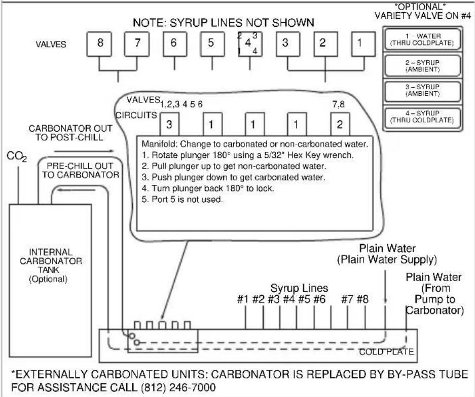
flowchart
graph TD
    A["VALVES"] --> B["8"]
    A --> C["7"]
    A --> D["6"]
    A --> E["5"]
    A --> F["4"]
    A --> G["3"]
    A --> H["2"]
    A --> I["1"]
    J["CARBONATOR OUT TO POST-CHILL"] --> K["CO2"]
    K --> L["PRE-CHILL OUT TO CARBONATOR"]
    L --> M["INTERNAL CARBONATOR TANK (Optional)"]
    M --> N["Syrup Lines #1 #2 #3 #4 #5 #6 #7 #8"]
    N --> O["COLD PLATE"]
    P["VALVES 1,2,3 4 5 6"] --> Q["Manifold: Change to carbonated or non-carbonated water."]
    Q --> R["1. Rotate plunger 180° using a 5/32" Hex Key wrench."]
    Q --> S["2. Pull plunger up to get non-carbonated water."]
    Q --> T["3. Push plunger down to get carbonated water."]
    Q --> U["4. Turn plunger back 180° to lock."]
    Q --> V["5. Port 5 is not used."]
    W["Plain Water (Plain Water Supply)"] --> X["Plain Water (From Pump to Carbonator)"]
    Y["*OPTIONAL* VARIETY VALVE ON #4"] --> Z["1 - WATER (THRU COLDPLATE)"]
    Y --> AA["2 - SYRUP (AMBIENT)"]
    Y --> AB["3 - SYRUP (AMBIENT)"]
    Y --> AC["4 - SYRUP (THRU COLDPLATE)"]
S/SV200/250 10 Valve Diagram
PLUMBING: 3-1-2-1-3 MANIFOLDING
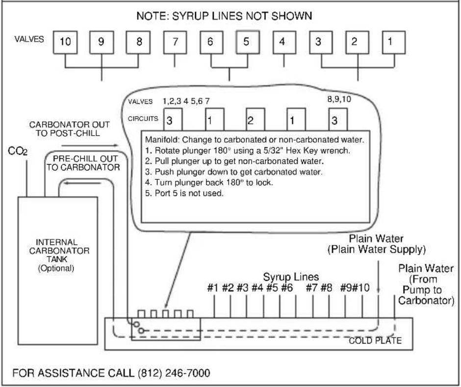
flowchart
graph TD
    A["VALVES 10"] --> B["CARBONATOR OUT TO POST-CHILL"]
    C["VALVES 1,2,3 4 5,6 7"] --> D["CIRCUITS 3 1 2 1 3"]
    E["VALVES 8,9,10"] --> F["Manifold: Change to carbonated or non-carbonated water."]
    G["CO2"] --> H["PRE-CHILL OUT TO CARBONATOR"]
    H --> I["INTERNAL CARBONATOR TANK (Optional)"]
    J["Syrup Lines #1 #2 #3 #4 #5 #6 #7 #8 #9#10"] --> K["Plain Water (Plain Water Supply)"]
    L["COLD PLATE"] --> M["Plain Water (From Pump to Carbonator)"]
    N["FOR ASSISTANCE CALL (812) 246-7000"]
NGF-250 & NGF-250QD 8 Valve Diagram
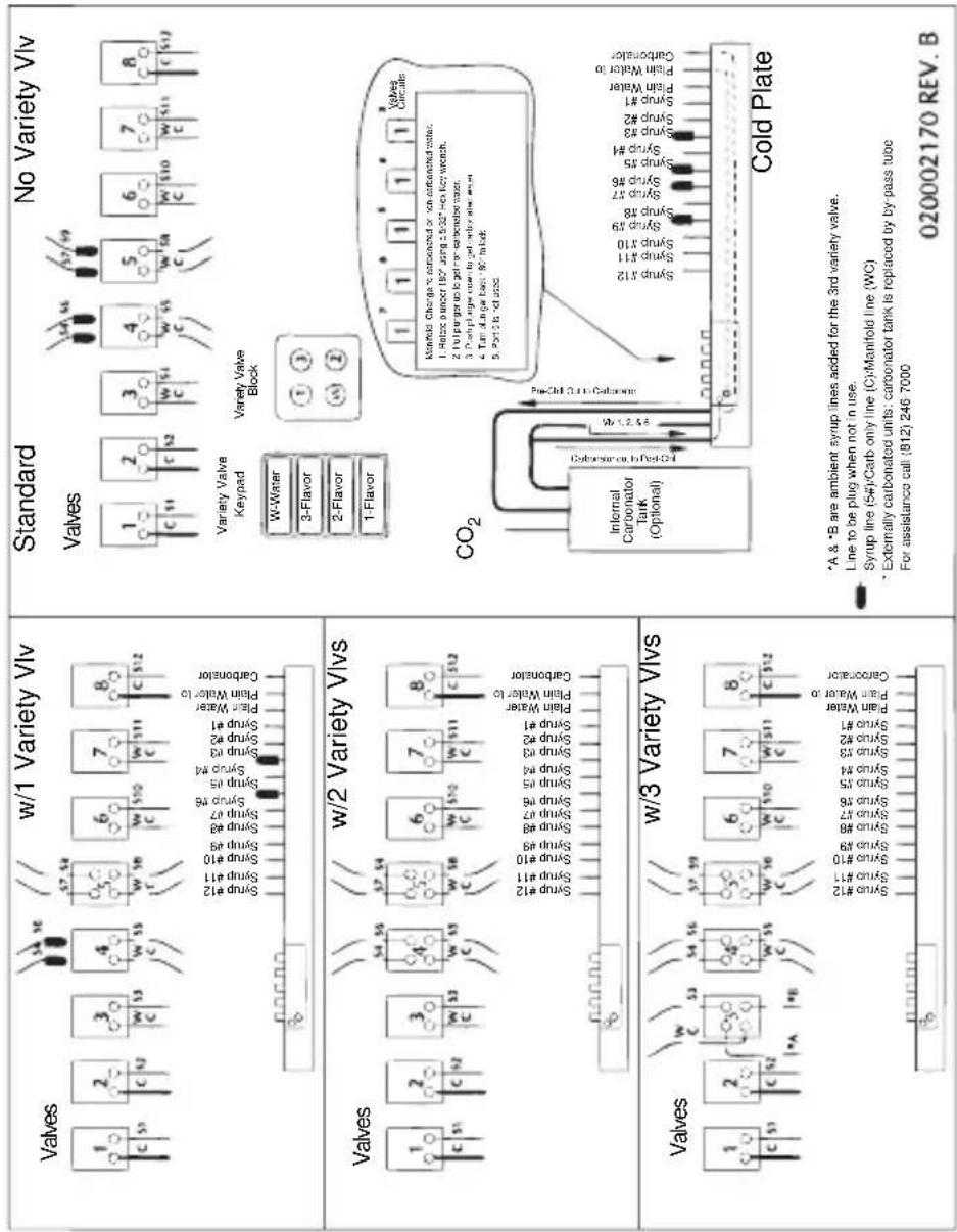
Flex Manifold Diagrams
FLEX MANIFOLD — 6 VALVE
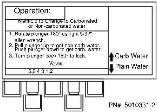
NOTE: 12 valve 302 units use 1 per side.
FLEX MANIFOLD — 8 VALVE
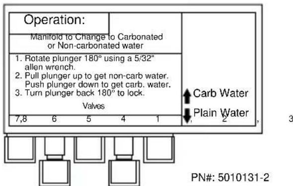
NOTE: 16 valve 402 units use 1 per side.
FLEX MANIFOLD — 10 VALVE
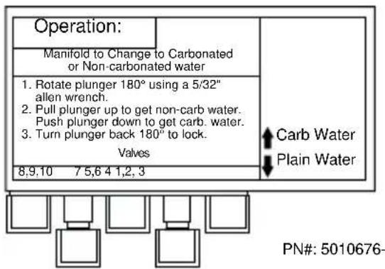
NOTE: 20 valve 402 units use 1 per side.
CEV Wiring
CEV-30i & 40i 115V 60HZ
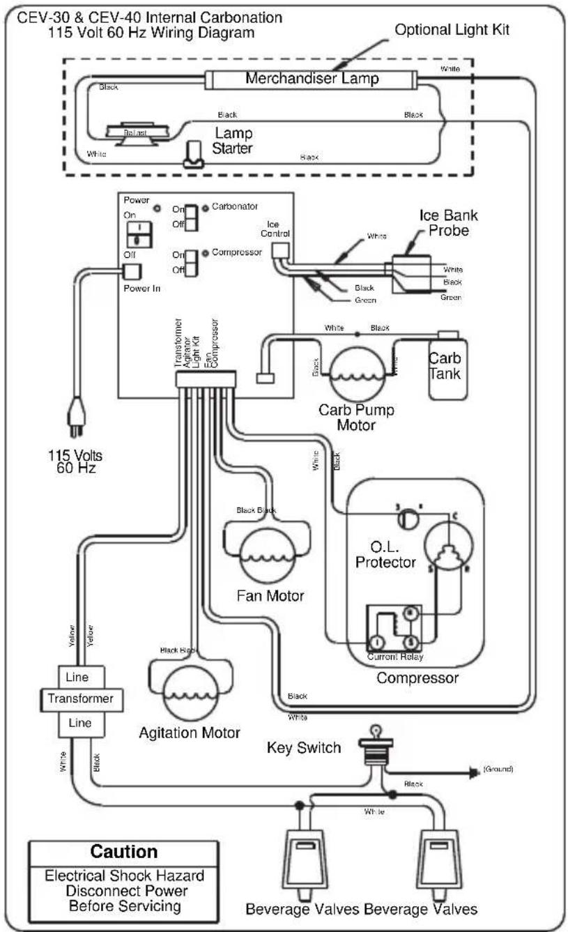
flowchart
graph TD
    A["CEV-30 & CEV-40 Internal Carbonation 115 Volt 60 Hz Wiring Diagram"] --> B["Lamp Starter"]
    B --> C["Merchandiser Lamp"]
    C --> D["Optional Light Kit"]
    D --> E["Ice Bank Probe"]
    E --> F["Carb Tank"]
    F --> G["Carb Pump Motor"]
    G --> H["O.L. Protector"]
    H --> I["Compressor"]
    I --> J["Key Switch"]
    J --> K["Beverage Valves Beverage Valves"]
    L["115 Volts 60 Hz"] --> M["Transformer"]
    M --> N["Agitation Motor"]
    N --> O["Line Transformer"]
    O --> P["Line"]
    P --> Q["Line"]
    Q --> R["Line"]
    R --> S["Line"]
    S --> T["Line"]
    T --> U["Line"]
    U --> V["Line"]
    V --> W["Line"]
    W --> X["Line"]
    X --> Y["Line"]
    Y --> Z["Line"]
    Z --> AA["Line"]
    AA --> AB["Line"]
    AB --> AC["Line"]
    AC --> AD["Line"]
    AD --> AE["Line"]
    AE --> AF["Line"]
    AF --> AG["Line"]
    AG --> AH["Line"]
    AH --> AI["Line"]
    AI --> AJ["Line"]
    AJ --> AK["Line"]
    AK --> AL["Line"]
    AL --> AM["Line"]
    AM --> AN["Line"]
    AN --> AO["Line"]
    AO --> AP["Line"]
    AP --> AQ["Line"]
    AQ --> AR["Line"]
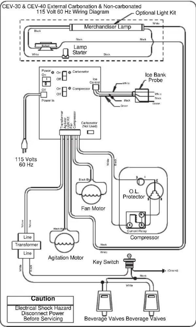
flowchart
graph TD
    A["CEV-30 & CEV-40 External Carbonation & Non-carbonated 115 Volt 60 Hz Wiring Diagram"] --> B["Lamp Starter"]
    B --> C["Merchandiser Lamp"]
    C --> D["Optional Light Kit"]
    D --> E["Ice Bank Probe"]
    E --> F["White Black Green"]
    F --> G["Black Black"]
    G --> H["Transformer Light Kit"]
    H --> I["Fan Motor"]
    I --> J["O.L. Protector"]
    J --> K["Current Relay"]
    K --> L["Compressor"]
    L --> M["Key Switch"]
    M --> N["Agitation Motor"]
    N --> O["Line Transformer"]
    O --> P["Line"]
    P --> Q["Caution: Electrical Shock Hazard Disconnect Power Before Servicing"]
    Q --> R["Beverage Valves Beverage Valves"]
    style A fill:#f9f,stroke:#333
    style B fill:#ccf,stroke:#333
    style C fill:#cfc,stroke:#333
    style D fill:#fcc,stroke:#333
    style E fill:#cff,stroke:#333
    style F fill:#ffc,stroke:#333
    style G fill:#cfc,stroke:#333
    style H fill:#fcc,stroke:#333
    style I fill:#ffc,stroke:#333
    style J fill:#cfc,stroke:#333
    style K fill:#fcc,stroke:#333
    style L fill:#ffc,stroke:#333
    style M fill:#cfc,stroke:#333
    style N fill:#fcc,stroke:#333
    style O fill:#ffc,stroke:#333
    style P fill:#cfc,stroke:#333
    style Q fill:#fcc,stroke:#333
    style R fill:#cfc,stroke:#333
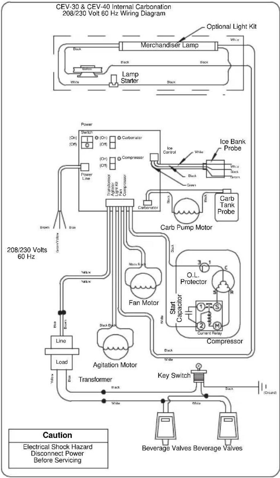
flowchart
graph TD
    A["CEV-30 & CEV-40 Internal Carbonation 208/230 Volt 60 Hz Wiring Diagram"] --> B["Lamp Starter"]
    B --> C["Merchandiser Lamp"]
    C --> D["Optional Light Kit"]
    C --> E["Ice Bank Probe"]
    C --> F["Carb Tank Probe"]
    C --> G["Carb Pump Motor"]
    G --> H["O.L. Protector"]
    G --> I["Compressor"]
    G --> J["Agitation Motor"]
    G --> K["Transformer"]
    G --> L["Key Switch"]
    M["208/230 Volts 60 Hz"] --> N["Line"]
    N --> O["Load"]
    O --> P["Blue"]
    P --> Q["Yellow"]
    Q --> R["Line"]
    R --> S["Power Line"]
    S --> T["Switch (On) (Off)"]
    T --> U["(On) (Off)"]
    U --> V["(On) (Off)"]
    V --> W["(On) (Off)"]
    W --> X["(On) (Off)"]
    X --> Y["(On) (Off)"]
    Y --> Z["(On) (Off)"]
    Z --> AA["(On) (Off)"]
    AA --> AB["(On) (Off)"]
    AB --> AC["(On) (Off)"]
    AC --> AD["(On) (Off)"]
    AD --> AE["(On) (Off)"]
    AE --> AF["(On) (Off)"]
    AF --> AG["(On) (Off)"]
    AG --> AH["(On) (Off)"]
    AH --> AI["(On) (Off)"]
    AI --> AJ["(On) (Off)"]
    AJ --> AK["(On) (Off)"]
    AK --> AL["(On) (Off)"]
    AL --> AM["(On) (Off)"]
    AM --> AN["(On) (Off)"]
    AN --> AO["(On) (Off)"]
    AO --> AP["(On) (Off)"]
    AP --> AQ["(On) (Off)"]
    AQ --> AR["(On) (Off)"]
    AR --> AS["(On) (Off)"]
    AS --> AT["(On) (Off)"]
    AT --> AU["(On) (Off)"]
    AU --> AV["(On) (Off)"]
    AV --> AW["(On) (Off)"]
    AW --> AX["(On) (Off)"]
    AX --> AY["(On) (Off)"]
    AY --> AZ["(On) (Off)"]
    AZ --> BA["(On) (Off)"]
    BA --> BB["(On) (Off)"]
    BB --> BC["(On) (Off)"]
    BC --> BD["(On) (Off)"]
    BD --> BE["(On) (Off)"]
    BE --> BF["(On) (Off)"]
    BF --> BG["(On) (Off)"]
    BG --> BH["(On) (Off)"]
    BH --> BI["(On) (Off)"]
    BI --> BJ["(On) (Off)"]
    BJ --> BK["(On) (Off)"]
    BK --> BL["(On) (Off)"]
    BL --> BM["(On) (Off)"]
    BM --> BN["(On) (Off)"]
    BN --> BO["(On) (Off)"]
    BO --> BP["(On) (Off)"]
    BP --> BQ["(On) (Off)"]
    BQ --> BR["(On) (Off)"]
    BR --> BS["(On) (Off)"]
    BS --> BT["(On) (Off)"]
    BT --> BU["(On) (Off)"]
    BU --> BV["(On) (Off)"]
    BV --> BW["(On) (Off)"]
    BW --> BX["(On) (Off)"]
    BX --> BY["(On) (Off)"]
    BY --> BZ["(On) (Off)"]
    BZ --> CA["(On) (Off)"]
    CA --> CB["(On) (Off)"]
    CB --> CC["(On) (Off)"]
    CC --> CD["(On) (Off)"]
    CD --> CE["(On) (Off)"]
    CE --> CF["(On) (Off)"]
    CF --> CG["(On) (Off)"]
    CG --> CH["(On) (Off)"]
    CH --> CI["(On) (Off)"]
    CI --> CJ["(On) (Off)"]
    CJ --> CK["(On) (Off)"]
    CK --> CL["(On) (Off)"]
    CL --> CD
    CD --> CD1["Water"]
    CD1 --> CD2["Water"]
    CD2 --> CD3["Water"]
    CD3 --> CD4["Water"]
    CD4 --> CD5["Water"]
    CD5 --> CD6["Water"]
    CD6 --> CD7["Water"]
    CD7 --> CD8["Water"]
    CD8 --> CD9["Water"]
    CD9 --> CD10["Water"]
    CD10 --> CD11["Water"]
    CD11 --> CD12["Water"]
    CD12 --> CD13["Water"]
    CD13 --> CD14["Water"]
    CD14 --> CD15["Water"]
    CD15 --> CD16["Water"]
    CD16 --> CD17["Water"]
    CD17 --> CD18["Water"]
    CD18 --> CD19["Water"]
    CD19 --> CD20["Water"]

    style A fill:#f9f,stroke:#333
    style B fill:#ccf,stroke:#333
    style C fill:#cfc,stroke:#333
    style D fill:#fcc,stroke:#333
    style E fill:#cff,stroke:#333
    style F fill:#ffc,stroke:#333
    style G fill:#fcf,stroke:#333
    style H fill:#cff,stroke:#333
    style I fill:#ffc,stroke:#333
    style J fill:#cfc,stroke:#333
    style K fill:#cfc,stroke:#333
    style L fill:#cfc,stroke:#333
    style M fill:#cfc,stroke:#333
    style N fill:#cfc,stroke:#333
    style O fill:#cfc,stroke:#333
    style P fill:#cfc,stroke:#333
    style Q fill:#cfc,stroke:#333
    style R fill:#cfc,stroke:#333
    style S fill:#cfc,stroke:#333
    style T fill:#cfc,stroke:#333
    style U fill:#cfc,stroke:#333
    style V fill:#cfc,stroke:#333
    style W fill:#cfc,stroke:#333
    style X fill:#cfc,stroke:#333
    style Y fill:#cfc,stroke:#333
    style Z fill:#cfc,stroke:#333
    style AA fill:#cfc,stroke:#333
    style AB fill:#cfc,stroke:#333
    style AC fill:#cfc,stroke:#333
    style AD fill:#cfc,stroke:#333
    style AE fill:#cfc,stroke:#333
    style AF fill:#cfc,stroke:#333
    style AG fill:#cfc,stroke:#333
    style AH fill:#cfc,stroke:#333
    style AI fill:#cfc,stroke:#333
    style AJ fill:#cfc,stroke:#333
    style AK fill:#cfc,stroke:#333
    style AL fill:#cfc,stroke:#333
    style AM fill:#cfc,stroke:#333
    style AN fill:#cfc,stroke:#333
    style AO fill:#cfc,stroke:#333
    style AP fill:#cfc,stroke:#333
    style AQ fill:#cfc,stroke:#333
    style AR fill:#cfc,stroke:#333
    style AS fill:#cfc,stroke:#333
    style AT fill:#cfc,stroke:#333
    style AU fill:#cfc,stroke:#333
    style AV fill:#cfc,stroke:#333
    style AW fill:#cfc,stroke:#333
    style AX fill:#cfc,stroke:#333
    style AY fill:#fcc,stroke:#333
CEV-30 & CEV-40 External Carbonation & Non-carbonation 208/230 Volt 60 Hz Wiring Diagram
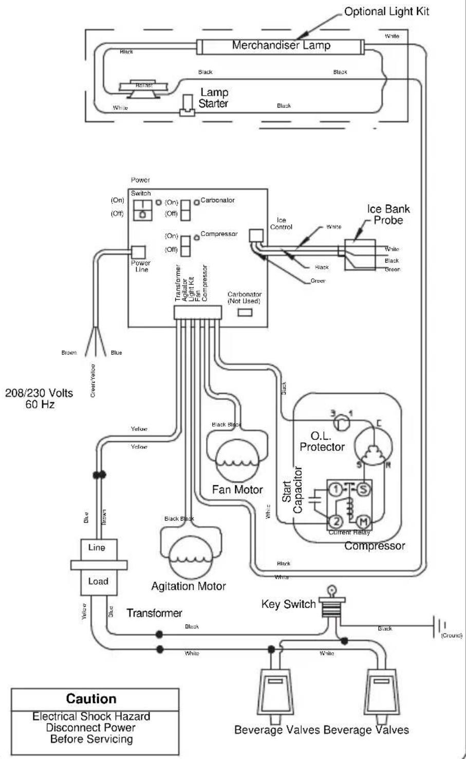
flowchart
graph TD
    A["Merchandiser Lamp"] --> B["Lamp Starter"]
    B --> C["Power Line"]
    C --> D["Transformer"]
    D --> E["Agitation Motor"]
    E --> F["Transformer"]
    F --> G["Key Switch"]
    G --> H["Beverage Valves"]
    H --> I["Compressor"]
    I --> J["O.L. Protector"]
    J --> K["Start Capacitor"]
    K --> L["Current Relay"]
    L --> M["Black Black"]
    M --> N["Fan Motor"]
    N --> O["Carbonator (Not Used)"]
    O --> P["Ice Control"]
    P --> Q["White"]
    Q --> R["Green"]
    R --> S["Black"]
    S --> T["White"]
    T --> U["Blue"]
    U --> V["Power Line"]
    V --> W["Switch"]
    W --> X["Color/Red"]
    X --> Y["Black"]
    Y --> Z["White"]
    Z --> AA["Blue"]
    AA --> AB["Power Line"]
    AB --> AC["Transformer"]
    AC --> AD["Agitation Motor"]
    AD --> AE["Carbonator (Not Used)"]
    AE --> AF["Ice Bank Probe"]
    AF --> AG["White"]
    AG --> AH["Green"]
    AH --> AI["Black"]
    AI --> AJ["White"]
    AJ --> AK["Blue"]
    AK --> AL["Power Line"]
    AL --> AM["Switch"]
    AM --> AN["Color/Red"]
    AN --> AO["Black"]
    AO --> AP["White"]
    AP --> AQ["Blue"]
    AQ --> AR["Power Line"]
    AR --> AS["Transformer"]
    AS --> AT["Agitation Motor"]
    AT --> AU["Carbonator (Not Used)"]
    AU --> AV["Ice Control"]
    AV --> AW["White"]
    AW --> AX["Green"]
    AX --> AY["Black"]
    AY --> AZ["White"]
    AZ --> BA["Blue"]
    BA --> BB["Power Line"]
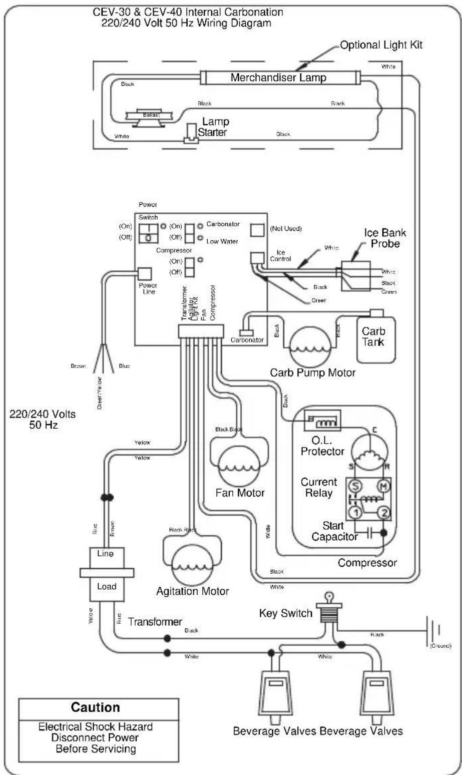
flowchart
graph TD
    A["220/240 Volts 50 Hz"] --> B["Power Line"]
    B --> C["Switch (On) (Off)"]
    C --> D["Compressor (On) (Off)"]
    D --> E["Transformer (Light Kit Fan Compressor)"]
    E --> F["Carbonator (Not Used)"]
    F --> G["Ice Control"]
    G --> H["Carb Tank"]
    H --> I["Carb Pump Motor"]
    I --> J["O.L. Protector"]
    J --> K["Current Relay"]
    K --> L["Start Capacitor"]
    L --> M["Compressor"]
    M --> N["Key Switch"]
    N --> O["Beverage Valves Beverage Valves"]
    P["Line"] --> Q["Load"]
    Q --> R["Transformer"]
    R --> S["Agitation Motor"]
    S --> T["Carbonator"]
    T --> U["Ice Bank Probe"]
    U --> V["Water"]
    V --> W["Bone"]
    W --> X["Blue"]
    X --> Y["Clear-Yes Out"]
    Y --> Z["Power Line"]
    Z --> AA["Switch (On) (Off)"]
    AA --> AB["Compressor (On) (Off)"]
    AB --> AC["Transformer (Light Kit Fan Compressor)"]
    AC --> AD["Bone"]
    AD --> AE["Blue"]
    AE --> AF["Clear-Yes Out"]
    AF --> AG["Power Line"]
    AG --> AH["Switch (On) (Off)"]
    AH --> AI["Compressor (On) (Off)"]
    AI --> AJ["Transformer (Light Kit Fan Compressor)"]
    AJ --> AK["Bone"]
    AK --> AL["Blue"]
    AL --> AM["Clear-Yes Out"]
    AM --> AN["Power Line"]
    AN --> AO["Switch (On) (Off)"]
    AO --> AP["Compressor (On) (Off)"]
    AP --> AQ["Transformer (Light Kit Fan Compressor)"]
    AQ --> AR["Bone"]
    AR --> AS["Blue"]
    AS --> AT["Clear-Yes Out"]
    AT --> AU["Power Line"]
    AU --> AV["Switch (On) (Off)"]
    AV --> AW["Compressor (On) (Off)"]
    AW --> AX["Transformer (Light Kit Fan Compressor)"]
    AX --> AY["Bone"]
    AY --> AZ["Blue"]
    AZ --> BA["Clear-Yes Out"]
    BA --> BB["Power Line"]
    BB --> BC["Switch (On) (Off)"]
    BC --> BD["Compressor (On) (Off)"]
    BD --> BE["Transformer (Light Kit Fan Compressor)"]
    BE --> BF["Bone"]
    BF --> BG["Blue"]
    BG --> BH["Clear-Yes Out"]
    BH --> BI["Power Line"]
    BI --> BJ["Switch (On) (Off)"]
    BJ --> BK["Compressor (On) (Off)"]
    BK --> BL["Transformer (Light Kit Fan Compressor)"]
    BL --> BM["Bone"]
    BM --> BN["Blue"]
    BN --> BO["Clear-Yes Out"]
    BO --> BP["Power Line"]
        BP --> BQ["Bone"]
        BQ --> BR["Blue"]
        BR --> BS["Clear-Yes Out"]
        BS --> BT["Bone"]
        BT --> BU["Blue"]
        BU --> BV["Bone"]
        BV --> BW["Bone"]
CEV-30 & CEV-40 External Carbonation & Non-carbonation 220/240 Volt 50 Hz Wiring Diagram
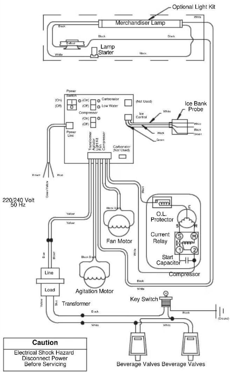
flowchart
graph TD
    A["Merchandiser Lamp"] --> B["Lamp Starter"]
    B --> C["Power Line"]
    C --> D["Transformer"]
    D --> E["Agitation Motor"]
    E --> F["Transformer"]
    F --> G["Key Switch"]
    G --> H["Beverage Valves"]
    H --> I["Compressor"]
    I --> J["O.L. Protector"]
    J --> K["Current Relay"]
    K --> L["Start Capacitor"]
    L --> M["Compressor"]
    M --> N["Ice Bank Probe"]
    N --> O["White Black Green"]
    O --> P["Ice Control"]
    P --> Q["Carbonator (Not Used)"]
    Q --> R["Light Kit"]
    R --> S["Compressor"]
    S --> T["Carbonator (Not Used)"]
    T --> U["Transformer"]
    U --> V["Agitation Motor"]
    V --> W["Agitation Motor"]
    W --> X["Line Load"]
    X --> Y["Brown Blue Yellow"]
    Y --> Z["Blue"]
    Z --> AA["Brown"]
    AA --> AB["Power Switch (On) Off"]
    AB --> AC["Compressor (On) Off"]
    AC --> AD["Transformer Agitator Light Kit Fan Compressor"]
    AD --> AE["Carbonator (Not Used)"]
    AE --> AF["Water (Off)"]
    AF --> AG["Black Black"]
    AG --> AH["Agitation Motor"]
    AH --> AI["Transformer"]
    AI --> AJ["Blue Black"]
    AJ --> AK["Brown Blue Yellow"]
    AK --> AL["Brown"]
    AL --> AM["Brown"]
    AM --> AN["Power Line"]
    AN --> AO["Transformer Agitator Light Kit Fan Compressor"]
    AO --> AP["Carbonator (Not Used)"]
    AP --> AQ["Water (Off)"]
    AQ --> AR["Black Black"]
    AR --> AS["Brown Blue Yellow"]
    AS --> AT["Brown Blue Yellow"]
    AT --> AU["Brown Blue Yellow"]
    AU --> AV["Brown Blue Yellow"]
    AV --> AW["Brown Blue Yellow"]
    AW --> AX["Brown Blue Yellow"]
CF Drop-In Series Wiring
CF-1522 115V
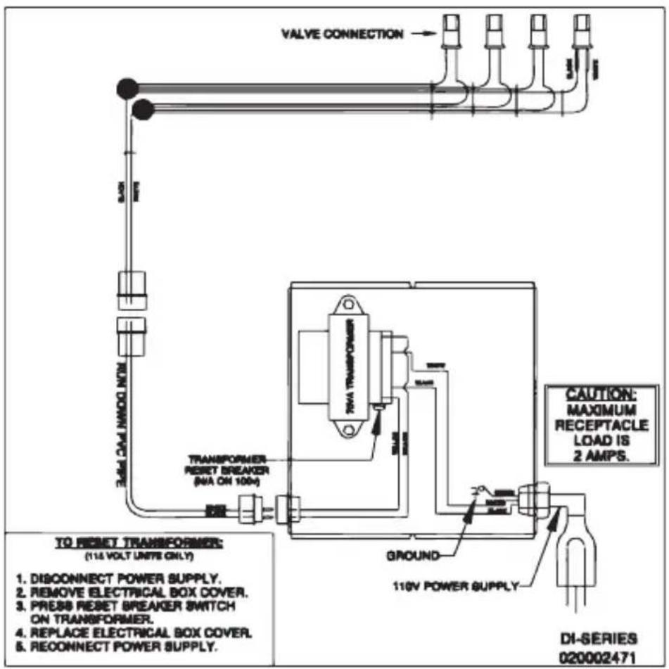
Drop-in Wiring
DI-SERIES IC 110V
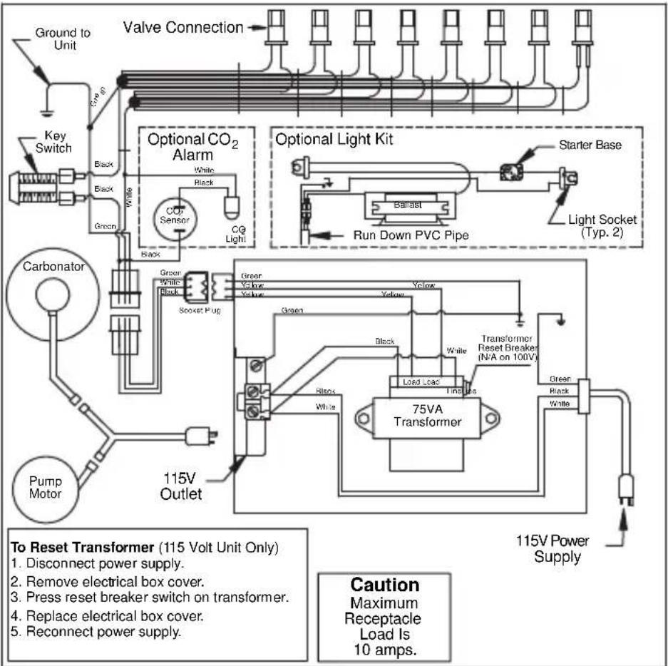
DI-SERIES IC 220-230V
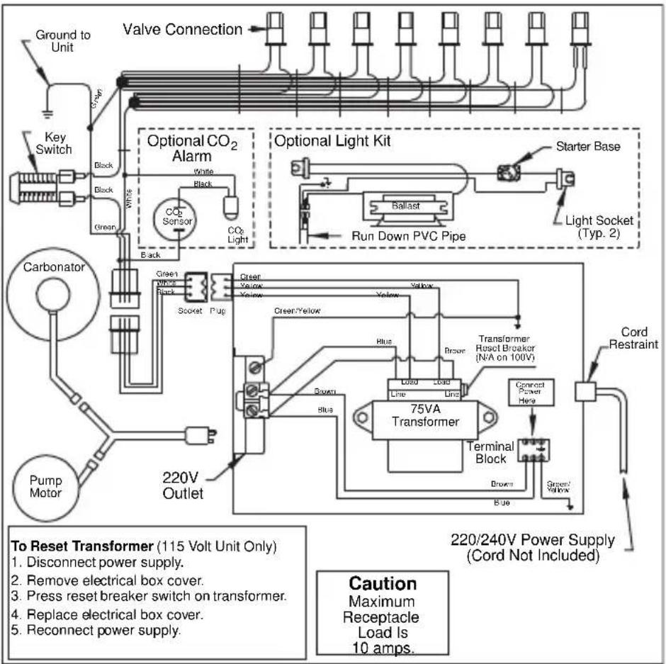
DI-SERIES AMBIENT 110V
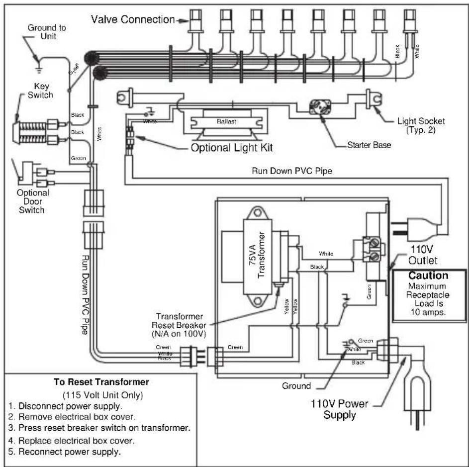
DI-SERIES AMBIENT 220-230V
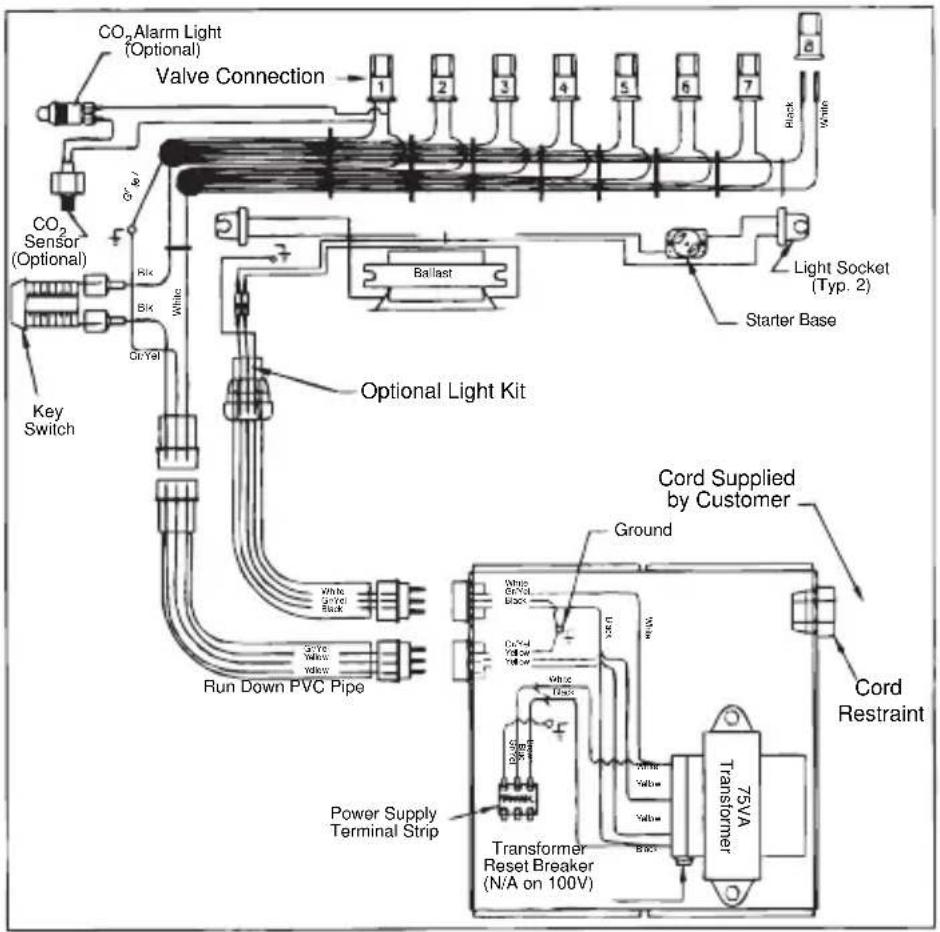
Flavor Magic Wiring
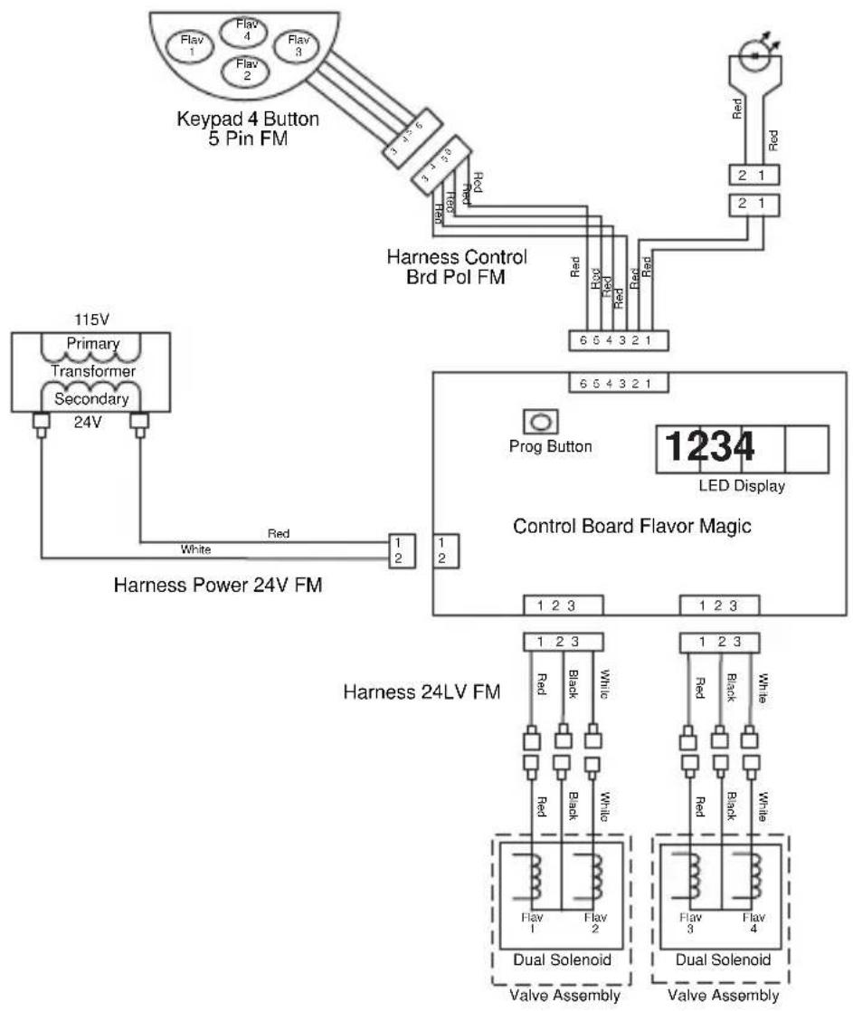
flowchart
graph TD
    A["Keypad 4 Button 5 Pin FM"] --> B["Harness Control Brd Pol FM"]
    B --> C["Prog Button"]
    C --> D["1234 LED Display"]
    E["115V Primary Transformer Secondary 24V"] --> F["Harness Power 24V FM"]
    F --> G["Harness 24LV FM"]
    G --> H["Dual Solenoid Valve Assembly"]
    G --> I["Dual Solenoid Valve Assembly"]
Flav'R-Pic (FRP-250) Wiring
FRP-250 (NON-CRUSHER) WIRING DIAGRAM
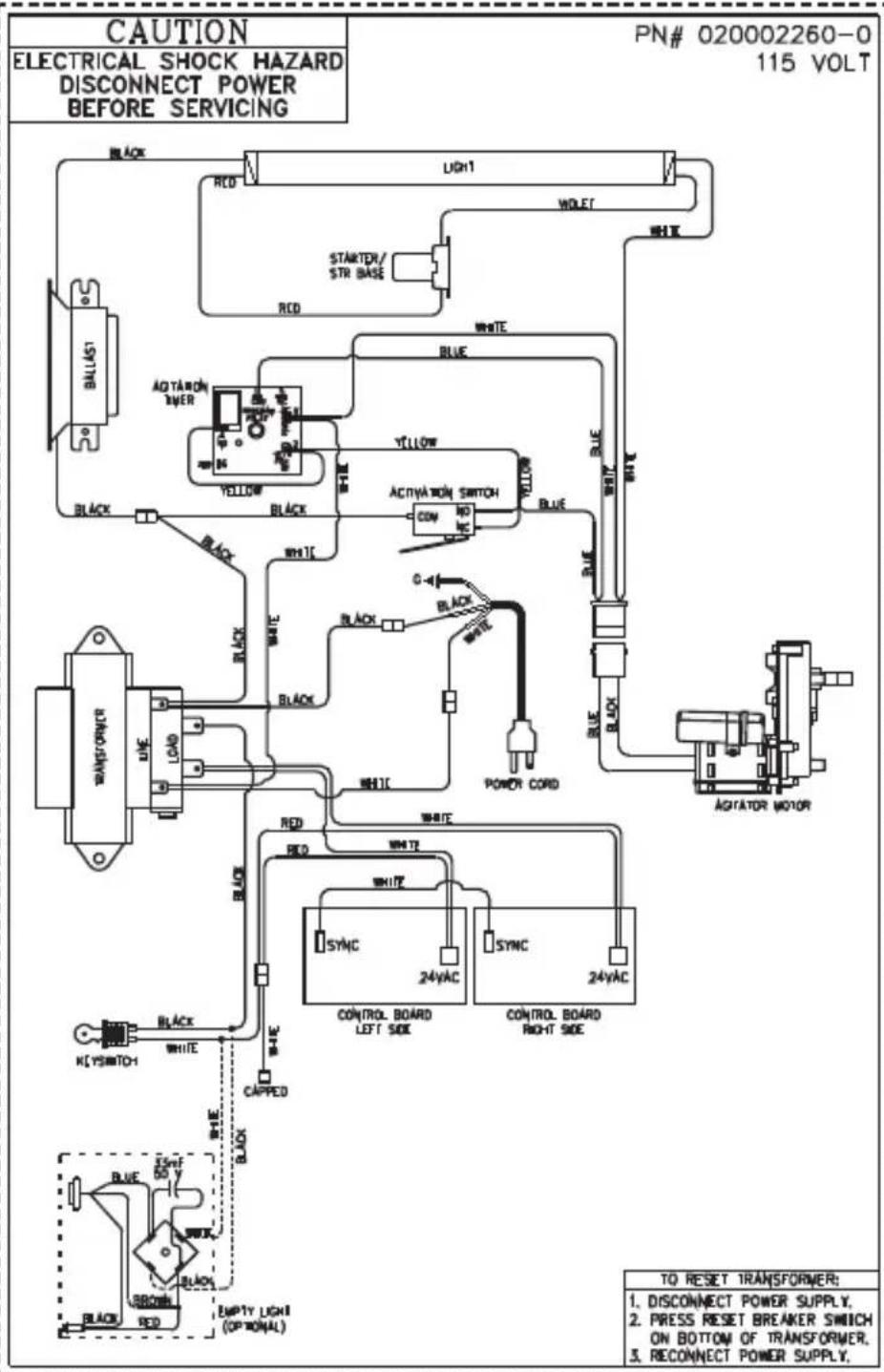
FRP-250SCI WIRING DIAGRAM
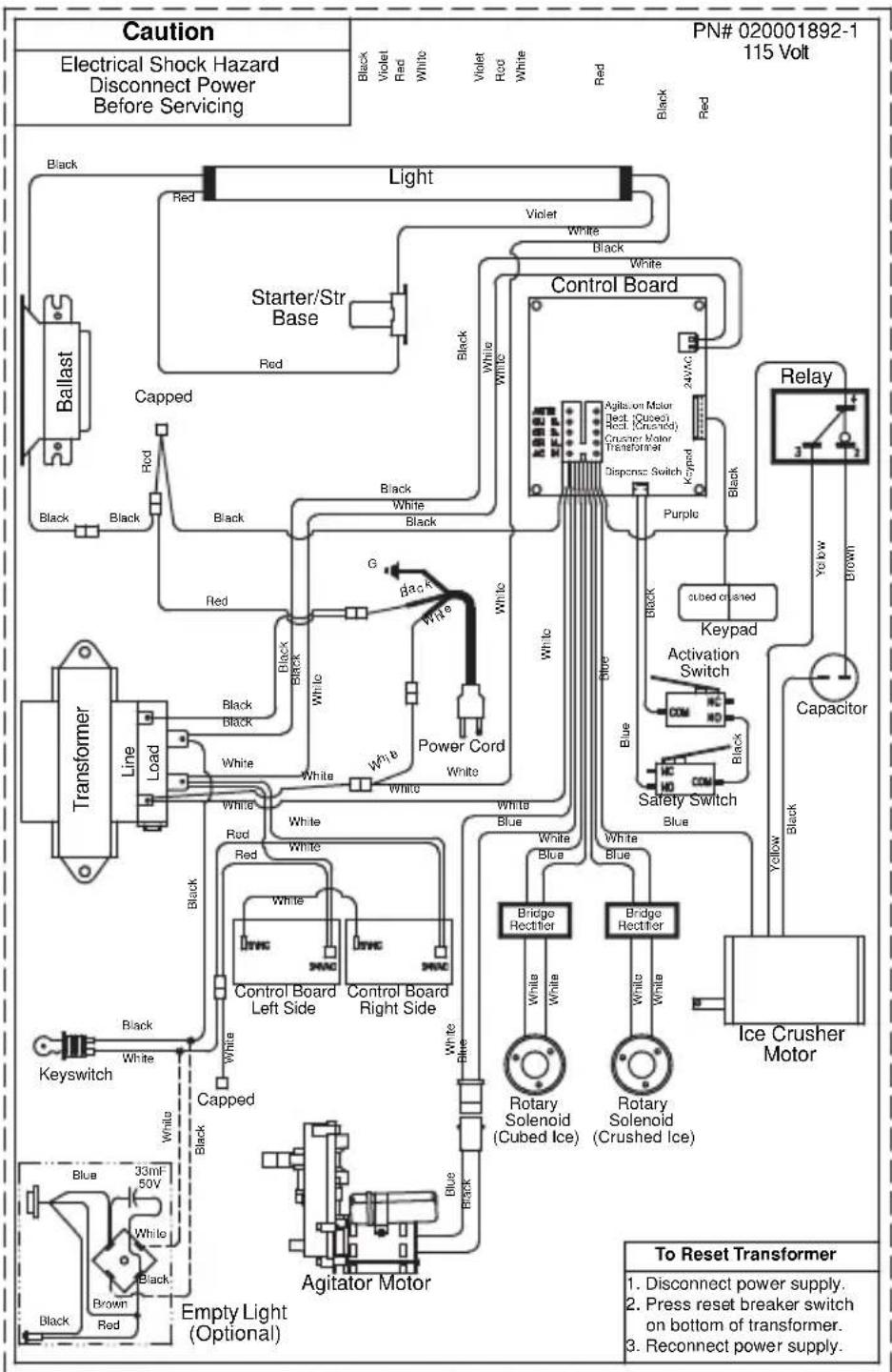
FlexTower Wiring
FT-8 WIRING DIAGRAM
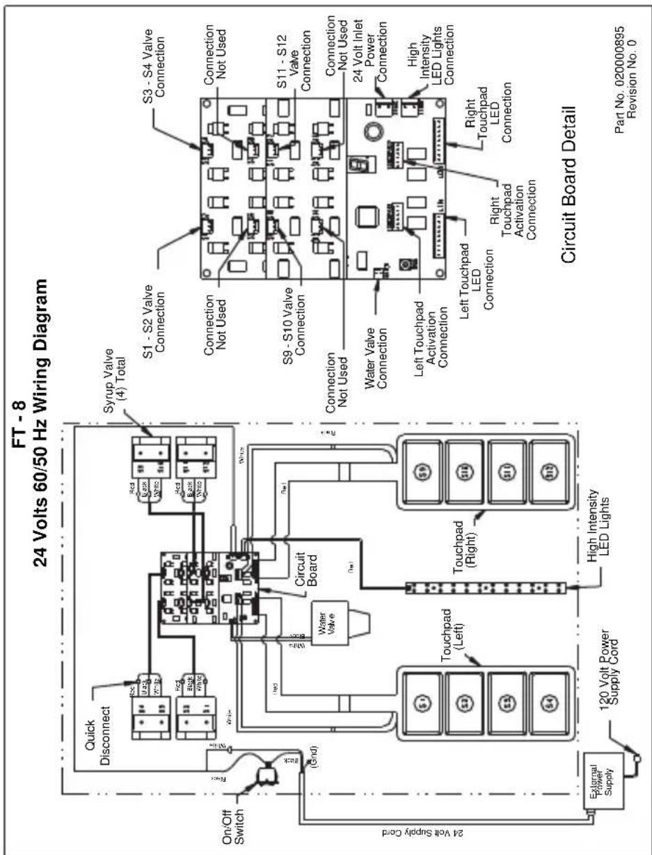
FT-12 WIRING DIAGRAM
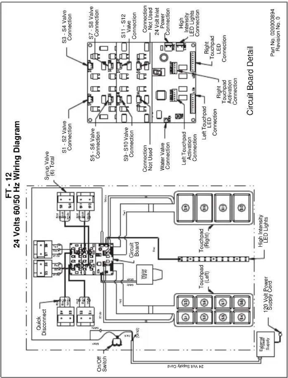
FT-16 WIRING DIAGRAM
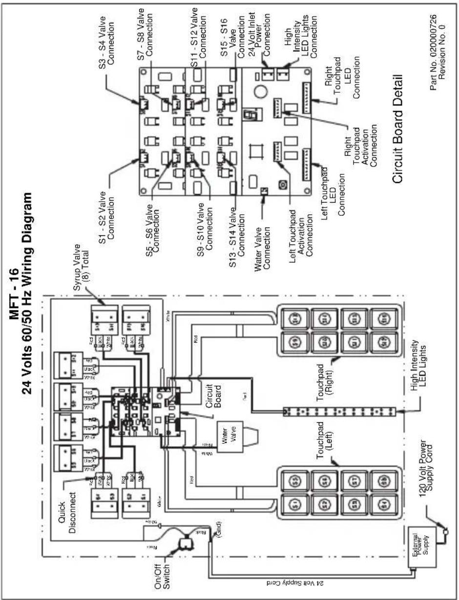
FLEXTOWER POWER SUPPLY
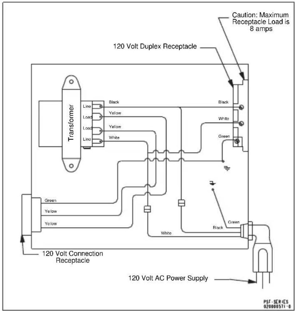
MDH-302 & MDH-402 Wiring
MDH 302 115V WIRING DIAGRAM
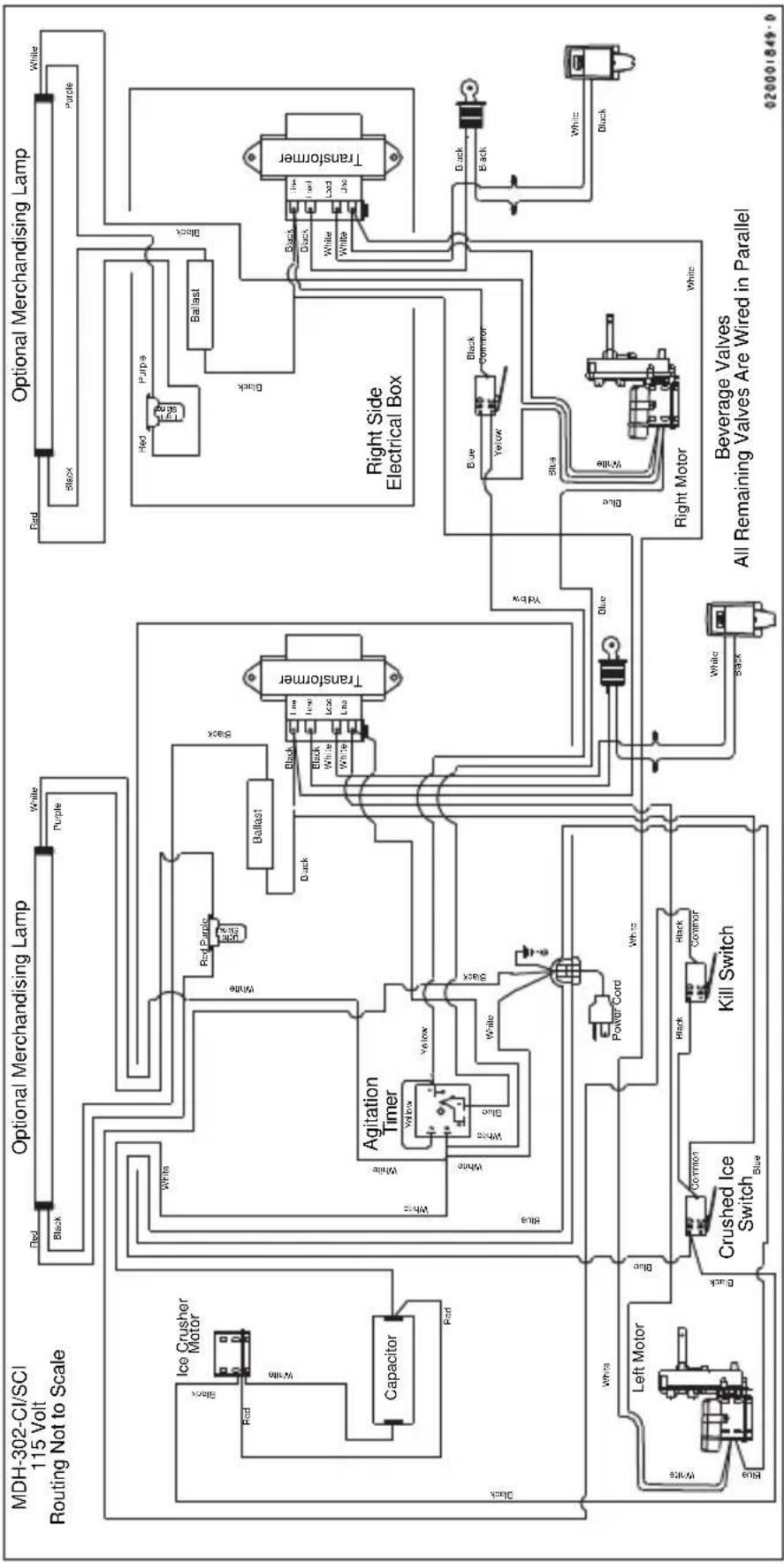
flowchart
graph TD
    subgraph MDH-302-CI/SCI 115 Volt Routing
        A["Capacitor"] --> B["Ice Crusher Motor"]
        B --> C["Red"]
        B --> D["White"]
        E["Black"] --> F["White"]
        G["Blue"] --> H["Black"]
        I["White"] --> J["Red Purple"]
        K["White"] --> L["Ballast"]
        M["White"] --> N["Black"]
        O["White"] --> P["White"]
        Q["White"] --> R["White"]
        S["White"] --> T["White"]
        U["White"] --> V["White"]
        W["White"] --> X["White"]
        Y["White"] --> Z["White"]
        AA["White"] --> AB["White"]
        AC["White"] --> AD["White"]
        AE["White"] --> AF["White"]
        AG["White"] --> AH["White"]
        AI["White"] --> AJ["White"]
        AK["White"] --> AL["White"]
        AM["White"] --> AN["White"]
        AO["White"] --> AP["White"]
        AQ["White"] --> AR["White"]
        AS["White"] --> AT["White"]
        AU["White"] --> AV["White"]
        AW["White"] --> AX["White"]
        AY["Capacitor"] --> AZ["Ice Crusher Motor"]
        BA["Ice Crusher Motor"] --> BB["Ballast"]
        BC["Ice Crusher Motor"] --> BD["Ballast"]
        BE["Ice Crusher Motor"] --> BF["Ballast"]
        BG["Ice Crusher Motor"] --> BH["Ballast"]
    end

    subgraph Optional Merchandising Lamp
        BI["Agitation Timer"] --> BJ["Yellow"]
        BK["Agitation Timer"] --> BL["Blue"]
        BM["Agitation Timer"] --> BN["White"]
        BO["Agitation Timer"] --> BP["White"]
        BQ["Agitation Timer"] --> BR["Black"]
        BS["Agitation Timer"] --> BT["Ballast"]
        BU["Agitation Timer"] --> BV["Ballast"]
        BW["Agitation Timer"] --> BX["Ballast"]
        BY["Agitation Timer"] --> BZ["Ballast"]
        CA["Agitation Timer"] --> CB["Ballast"]
    end

    subgraph Optional Merchandising Lamp
        CC["Agitation Timer"] --> CD["Yellow"]
        CE["Agitation Timer"] --> CF["Ballast"]
        GD["Agitation Timer"] --> DH["Ballast"]
        DI["Agitation Timer"] --> DJ["Ballast"]
        DK["Agitation Timer"] --> DL["Ballast"]
    end

    subgraph Right Side Electrical Box
        EQ["Agitation Timer"] --> AR["Yellow"]
        AS["Agitation Timer"] --> AS["Ballast"]
        AT["Agitation Timer"] --> AU["Ballast"]
        AV["Agitation Timer"] --> AVB["Ballast"]
    end

    subgraph Right Motor
        AW["Agitation Timer"] --> AX["Ballast"]
        AY["Agitation Timer"] --> AZ["Ballast"]
        BA["Yellow"] --> BAb["Ballast"]
        BB["Yellow"] --> BBb["Ballast"]
    end

    subgraph Beverage Valves
        BC["Agitation Timer"] --> BD["Ballast"]
        BE["Agitation Timer"] --> BF["Ballast"]
        BG["Agitation Timer"] --> BGb["Ballast"]
    end

    note1["All Remaining Valves Are Wired in Parallel"]
    note2["Beverage Valves"]
    note3["All Remaining Valves Are Wired in Parallel"]
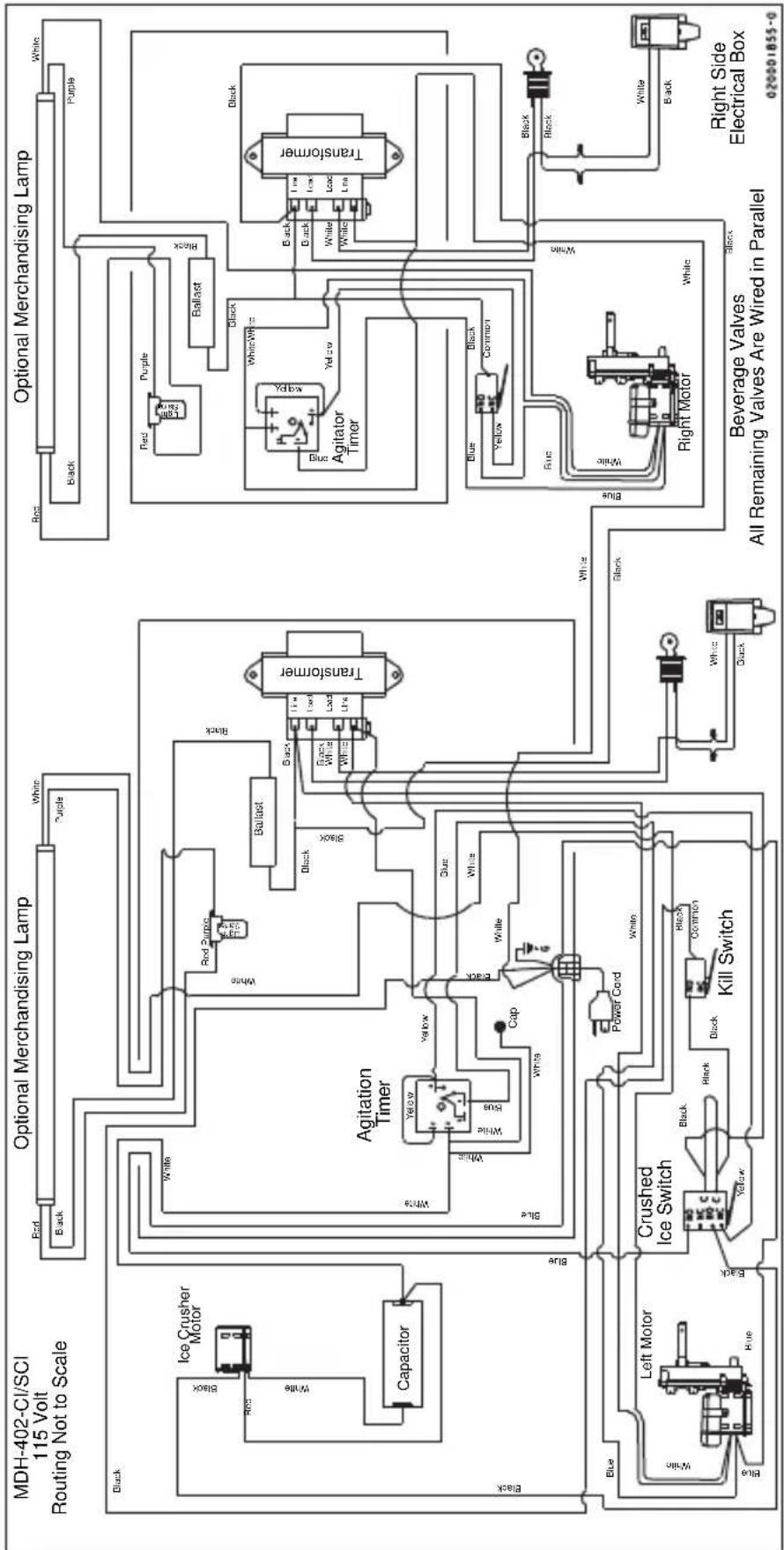
flowchart
graph TD
    subgraph MDH-402-CI/SCI 115 Volt Routing
        A["Capacitor"] --> B["Ice Crusher Motor"]
        B --> C["Black"]
        C --> D["White"]
        D --> E["White"]
        E --> F["Agitation Timer"]
        F --> G["Yellow"]
        F --> H["Blue"]
        F --> I["White"]
        I --> J["Power Cord"]
        J --> K["Black Common"]
        K --> L["Crushed Ice Switch"]
        L --> M["Blue"]
        L --> N["White"]
        N --> O["Kill Switch"]
    end

    subgraph Optional Merchandising Lamp
        P["Transformer"] --> Q["Red Purple Black Black Black White"]
        P --> R["Black White Load Line Black White"]
        P --> S["Red Light Blue Black Black White"]
        P --> T["Light Blue Black White"]
        P --> U["Ballast Black Black White"]
        P --> V["Bullast Black White"]
        P --> W["Agitator Timer"]
        W --> X["Blue Yellow Common Blue"]
        W --> Y["White Black White"]
        W --> Z["White Black White"]
        W --> AA["White Black White"]
        W --> AB["White Black White"]
    end

    subgraph Optional Merchandising Lamp
        AC["Transformer"] --> AD["Red Purple Black Black White"]
        AC --> AE["Red Light Blue Black White"]
        AC --> AF["Ballast Black Black White"]
        AC --> AG["Agitator Timer"]
        AG --> AH["Blue Yellow Common Blue"]
        AG --> AI["White Black White"]
        AG --> AJ["White Black White"]
        AG --> AK["White Black White"]
        AG --> AL["White Black White"]
    end

    subgraph Beverage Valves
        AM["Right Motor"] --> AN["Black Common Blue"]
        AN --> AO["White Black White"]
        AP["Big Box"] --> AQ["Black Black White"]
        AR["Electrical Box"] --> AS["White Black White"]
    end

    subgraph All Remaining Valves Are Wired in Parallel
        AT["Power Cord"] --> AU["Black Common Blue"]
        AU --> AV["White Black White"]
        AW["Power Cord"] --> AX["Black Common Blue"]
        AY["Power Cord"] --> AZ["Black Common Blue"]
    end

    style MDH-402-CI/SCI 115 Volt Routing fill:#f9f,stroke:#333
    style Optional Merchandising Lamp fill:#ccf,stroke:#333
    style Beverage Valves fill:#cfc,stroke:#333
    style All Remaining Valves Are Wired in Parallel fill:#fcc,stroke:#333
NGF-250 Wiring
NGF-250 115V WIRING DIAGRAM
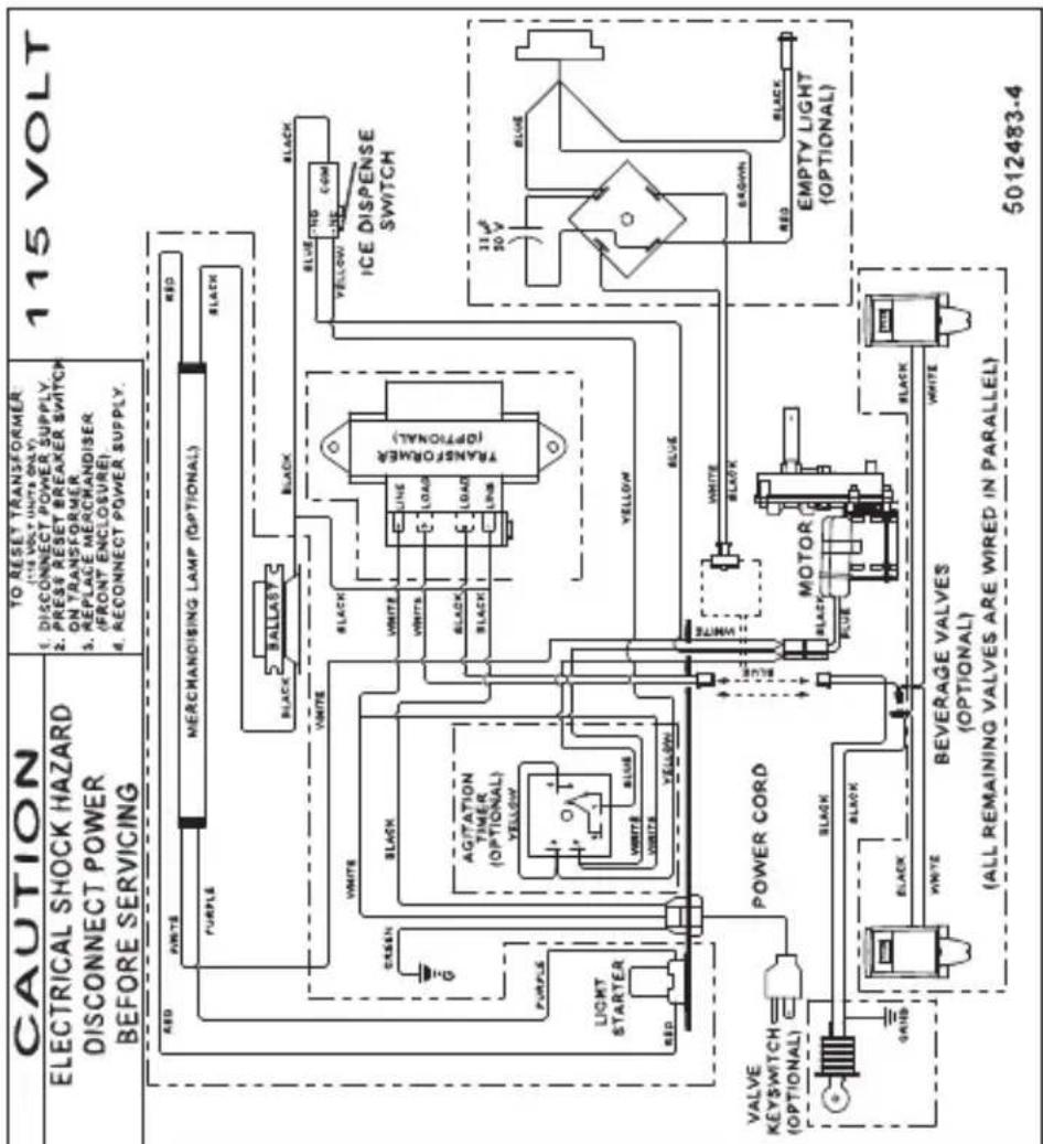
quickdraw Wiring
NFG-250 QD & SV-250 QD 115V WIRING DIAGRAM
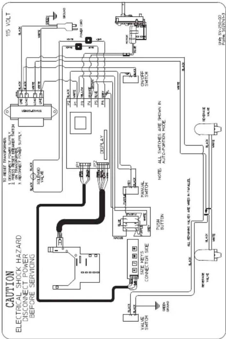
S/SV/SVi Wiring
S-SV-SVI-150/175/200/250 115V 60HZ
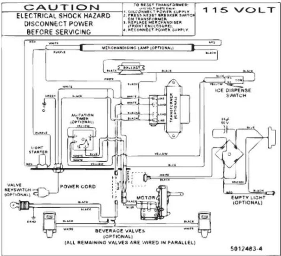
S-SV-SVI-150/175/200/250 100/220-240V 50-60HZ
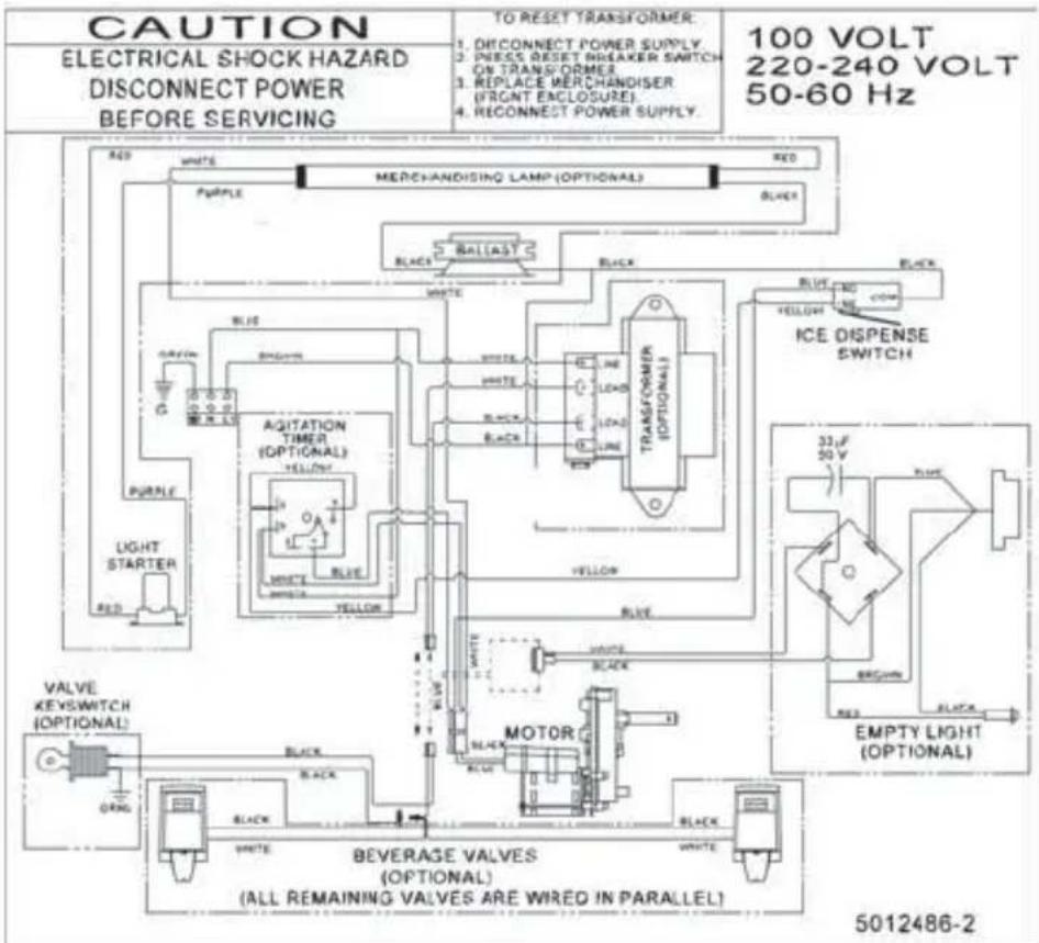
S-SV-SVI-150/175/200/250 220-240V 50HZ C.E.
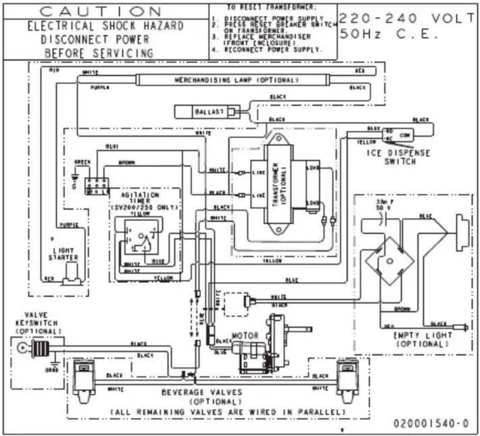
Selectable Ice Wiring
SV-200SCI & SV-250SCI 115V 60HZ
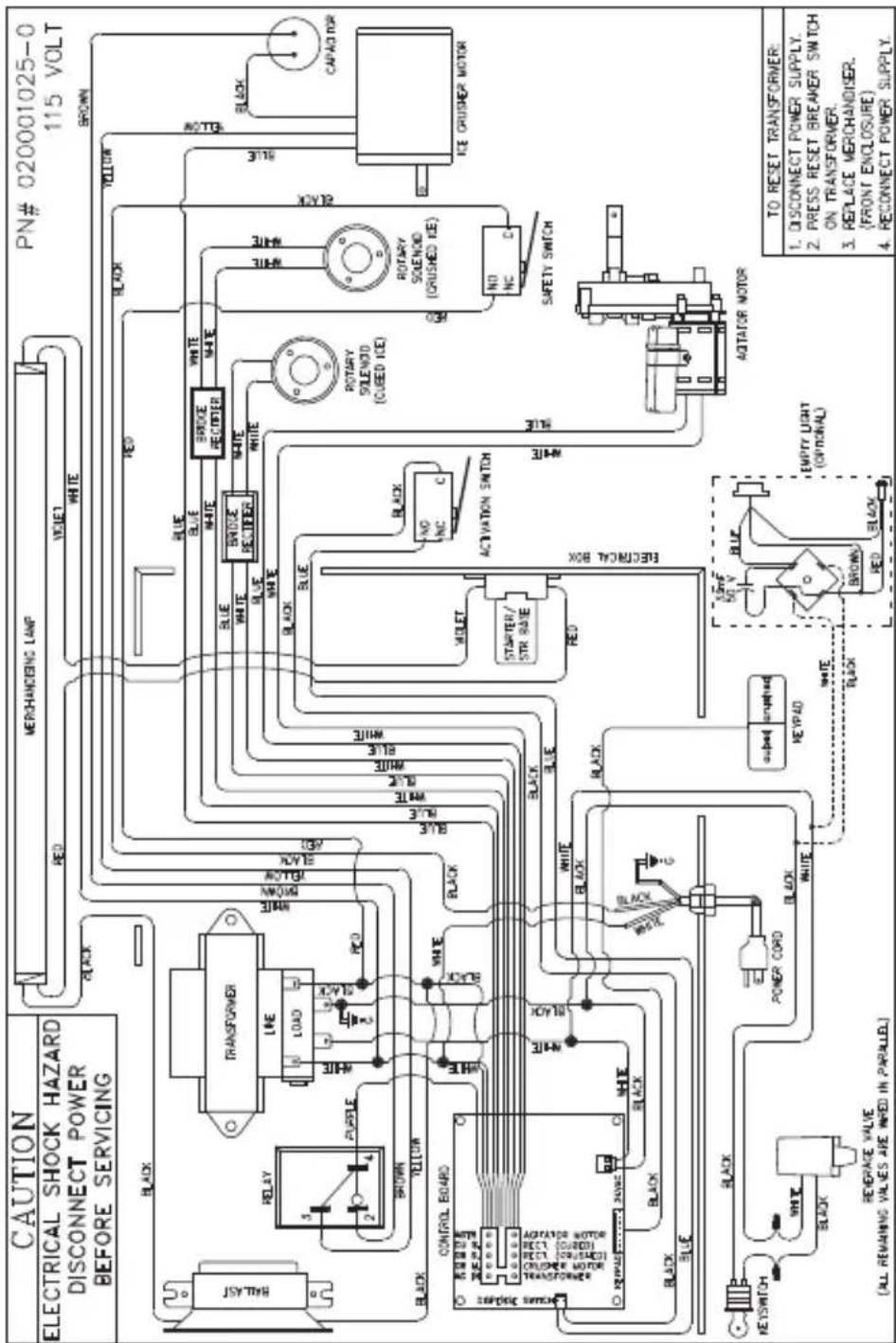
This Page Intentionally Left Blank
Manitowoc
Servend
Manitowoc Foodservice
2100 Future Drive
Sellersburg, IN 47172, USA
Ph: 812-246-7000 Fax: 812-246-7024
Visit us online at:
www.manitowocfsg.com
- Servend Ice & Beverage Dispensing Units
- Technician's Handbook
- Safety Notices
- Warning
- Caution
- Procedural Notices
- Important
- Read These Before Proceeding:
- PERSONAL INJURY POTENTIAL
- Table of Contents
- General Information
- Installation
- Component Identification
- Maintenance
- Operation
- Troubleshooting
- Component Specifications
- Charts
- Diagrams
- This Page Intentionally Left Blank
- Model Numbers
- Dispensing Basics
- WHAT IS CARBONATION
- WATER CHARACTERISTICS
- WATER FILTERS
- WATER PRESSURES
- SYRUP BASICS
- PREMIX
- POSTMIX
- PIPING
- Accessories
- BAFFLE FOR MANITOWOC® ICE MACHINES
- MANUAL FILL LID FOR DISPENSERS WITH AN ICE MACHINE
- LEGS
- Serial Number Location
- Warranty Information
- General
- Dimensions
- ICE/BEVERAGE & COUNTER ELECTRIC DISPENSER DIMENSIONS
- ICE/BEVERAGE & COUNTER ELECTRIC DISPENSER FOOTPRINTS
- DROP-IN & CT FOOTPRINTS
- DI/DIL-1522 & 2323
- Pre-installation Checklist
- TOP MOUNTED ICE MACHINE INSTALLATIONS
- Location
- Drains
- Rear View
- Water Supply
- RECOMMENDED PLUMBING
- Setting Pressures
- PRE-MIX PRESSURES
- COLD CARB AND AMBIENT SYSTEM PRESSURES
- BACK ROOM PACKAGE
- Typical Systems
- System Components
- BLADE TOWER
- Ice/Beverage and Counter Electric Dispensers
- NOTE:
- Cleaning
- ICE/BEVERAGE & COUNTER ELECTRIC DAILY CLEANING
- Electric Shock Hazard
- Clean the exterior and drain pan:
- Clean the dispensing valves:
- Nozzle Removal
- ICE/BEVERAGE AND COUNTER ELECTRIC MONTHLY CLEANING
- CLEANING CHECKLIST
- CEV WATER BATH
- Disassembly
- DISASSEMBLY FOR CLEANING AND MAINTENANCE (ICE/BEVERAGE DISPENSERS)
- Non-front Serviceable Motor
- Front Serviceable Motor
- Front Serviceable
- DISASSEMBLE THE ROCKING CHUTE
- How to Disassemble Tower Components
- Tower and Valve Disassembly:
- Maintenance Schedule
- Nightly Shutdown Procedure
- FLEXTOWER DAILY CLEANING
- QUICKDRAW COMPONENTS
- SELECTABLE ICE CRUSHER DISASSEMBLY
- REASSEMBLE THE ICE CRUSHER ASSEMBLY
- Replacement
- NON-FRONT SERVICEABLE GEAR MOTOR REMOVAL
- FRONT SERVICEABLE GEAR MOTOR REMOVAL
- Sanitizing
- BEVERAGE SYSTEM CLEANING
- BAG-IN-BOX SYSTEM SANITATION
- The procedure below is for the sanitation of one syrup circuit at a time. Repeat to sanitize additional circuits.
- Shipping, Storage and Relocation
- Blade Tower Brixing
- Set water flow rate first:
- Set the syrup flow rate:
- Flavor Magic Programming
- PROGRAM DISPENSE TIME
- PURGE/SANITIZE
- DISPENSING MODES
- Normal Dispense
- Flavor Counter
- CHANGING NUMBER OF ACTIVE FLAVORS
- TIME DELAY AFTER DISPENSE
- Flav'R-Pic External Programming HOW TO CHECK FRP BRIX EXTERNALLY
- FRP-250 with out Flavor Shots
- CRUSHED OR CUBED DEFAULT
- How to set default ice dispense setting
- CUBE DEFAULT
- CRUSH DEFAULT
- LAST SELECTION DEFAULT
- Flav'R-Pic (FRP-250) Programming
- PROGRAM MODE 1
- Carb/Non-Carb & Flavor Shot Duration Settings
- Flavor Shot Dispense Duration
- PROGRAM MODE 2
- Brixing
- PROGRAM MODE 3
- Light Sequences
- CONTROL BOARD TIME OUT
- Flav'R-Pic (FRP-250) Brixing Procedure
- PLACING A CONTROL BOARD INTO BRIX MODE
- GENERAL BRIXING PROCESS
- Nozzle 1 (N1) Water & Syrup Brixing
- Nozzle 2 (N2) Water & Syrup Brixing
- Nozzle 3 (N3) Carb/Non-Carb Water & Syrup Brixing
- Nozzle 4 (N4) Carb/Non-Carb Water & Syrup Brixing
- Nozzle 5 (N5) Water & Syrup Brixing
- Nozzle 6 (N6) Water & Syrup Brixing
- CONTROL BOARD RUN OR DISPENSE MODE
- THE 6 PROGRAMMING MODES ON FLEXTOWER CONTROL BOARD
- To Access Programming Modes
- To Exit Programming Modes
- Manual Dispense Mode
- Timed Dispense Mode (Flavor Adder Dispensed)
- Water Calibration Mode
- Syrup Calibration Mode
- Touchpad Configuration Mode
- Touchpad LED Light Sequencing Mode (8 Selection Area Touchpad)
- Touchpad LED Light Sequencing Mode (4 Selection Area Touchpad)
- Adjustments
- QUICKDRAW ICE PORTION ADJUSTMENTS
- ROCKING CHUTE ICE DELIVERY SWITCH ADJUSTMENT
- Agitation Timer
- Checklist
- Diagnosing a Defective Carbonator
- Electrical Requirements
- VOLTAGE
- Minimum Circuit Ampacity
- Minimum Circuit Amperage Chart
- Grounding Instructions
- Pump Deck Wiring
- Blade Tower Plumbing
- SINGLE TOWER
- CEV-30i & CEV-30e Plumbing
- CEV-40i & CEV-40e Plumbing
- CEV-30j Plumbing
- CT-6 Plumbing and Wiring
- CT-8 Plumbing and Wiring
- CF-1522 Plumbing
- Conversion for non-carbonated flavor
- DI-1522 Post-mix Plumbing
- SERVEND RECOMMENDED PLUMBING: DI-1522 IC
- DI-1522 Pre-mix Plumbing
- DI/DIL-2323 6 Valve Post-mix Plumbing
- DI/DIL-2323 8 Valve Post-mix Plumbing & Variety Valve
- DI/DIL-2323 10 Valve Post-mix Plumbing
- DI/DIL-2323 6 Valve Pre-mix Plumbing
- FRP-250 Plumbing Diagram
- FT-8 Plumbing
- FT-12 Plumbing
- MDH-302 12 Valve Plumbing
- MDH-402 16 Valve Plumbing
- MDH-402 20 Valve Plumbing
- S/SV150 6 Valve Diagram
- S/SV175 8 Valve Diagram
- S/SV200/250/SV-250QD 8 Valve Diagram
- S/SV200/250 10 Valve Diagram
- NGF-250 & NGF-250QD 8 Valve Diagram
- Flex Manifold Diagrams
- FLEX MANIFOLD — 6 VALVE
- FLEX MANIFOLD — 8 VALVE
- FLEX MANIFOLD — 10 VALVE
- CEV Wiring
- CEV-30i & 40i 115V 60HZ
- CF Drop-In Series Wiring
- Drop-in Wiring
- DI-SERIES IC 110V
- DI-SERIES IC 220-230V
- DI-SERIES AMBIENT 110V
- DI-SERIES AMBIENT 220-230V
- Flav'R-Pic (FRP-250) Wiring
- FRP-250 (NON-CRUSHER) WIRING DIAGRAM
- FRP-250SCI WIRING DIAGRAM
- FlexTower Wiring
- FT-8 WIRING DIAGRAM
- FT-12 WIRING DIAGRAM
- FT-16 WIRING DIAGRAM
- FLEXTOWER POWER SUPPLY
- MDH-302 & MDH-402 Wiring
- MDH 302 115V WIRING DIAGRAM
- NGF-250 Wiring
- NGF-250 115V WIRING DIAGRAM
- quickdraw Wiring
- NFG-250 QD & SV-250 QD 115V WIRING DIAGRAM
- S/SV/SVi Wiring
- S-SV-SVI-150/175/200/250 115V 60HZ
- S-SV-SVI-150/175/200/250 100/220-240V 50-60HZ
- Selectable Ice Wiring
- SV-200SCI & SV-250SCI 115V 60HZ
- Manitowoc
Brand : Servend
Model : S-150
Category : Ice Maker