
EL-25 - Deep fryer Cecilware - Free user manual and instructions
Find the device manual for free EL-25 Cecilware in PDF.


| Product Type | Electric Countertop Deep Fryer |
| Model | EL-25 |
| Oil Capacity | 15 lb (approx. 7 L) |
| Power Supply | 240V, 3.2kW, 15A, single phase |
| Dimensions (W x D x H) | 11 x 17.5 x 15.75 inches |
| Construction | Stainless steel body and oil pan |
| Temperature Range | Adjustable thermostat, typically 325°F – 358°F for general cooking |
| Control Type | Thermostat dial with indicator lights (amber for power, red for heating) |
| Included Accessories | One fry basket, element guard, oil pan, manual |
| Safety Features | Thermal cut-out, hi-limit thermostat, micro-switch, cULus listed, NSF certified |
| Cleaning Method | Warm soapy water; control box must not be immersed; wipe with damp cloth |
| Maintenance | Daily cleaning recommended; oil filtration recommended using Cecilware Frysaver |
| Installation Requirements | Firm level surface; keep away from combustibles; single tank: one power cord; double tanks: two cords on separate circuits |
| Warranty | Not specified in manual; contact dealer for details |
| Spare Parts Availability | Parts listed for EL-25: basket, hi-limit, thermostat dial, thermostat, cord & plug, pilot light, heating element, micro switch, etc. |
| Repair Service | Only Cecilware recommended qualified service technicians |
Frequently Asked Questions - EL-25 Cecilware
User questions about EL-25 Cecilware
0 question about this device. Answer the ones you know or ask your own.
Ask a new question about this device
Download the instructions for your Deep fryer in PDF format for free! Find your manual EL-25 - Cecilware and take your electronic device back in hand. On this page are published all the documents necessary for the use of your device. EL-25 by Cecilware.
USER MANUAL EL-25 Cecilware
ELECTRIC COUNTER TOP
FRYER
Single & Double models
OPERATION MANUAL
EL-6
EL-15
EL-25
EL-2x6
EL-2x15
EL-2x25

natural_image
Exterior view of a stainless steel two-fried kitchen<|im_start|> Puerto Rico electric oven with control knobs and side grilles (no visible text or symbols)EL-2x6 Shown

CECILWARE CORPORATION
43-05 20 ^th AVENUE, LONG ISLAND CITY, NEW YORK 11105-1295.
718-932-1414
FAX 718-932-7860
www.cecilware.com
TABLE OF CONTENTS
Introduction ...... page 2
Packaging ...... page 2
Installation ...... page 2-3
Operation ...... page 3
Cleaning, Care and Maintenance ...... page 4
Safety ...... page 4
Trouble Shooting ...... page 5
Compliance ...... page 6
Electrical Diagram ...... page 6
Explosion View ...... page 7-8
Spare Part List ...... page 9
Specifications ...... page 10
Introduction
Congratulations on the purchase of your Cecilware Counter Top Fryer. Please take time to carefully read through this manual to ensure the machine is operated and maintained properly. This will enable the best possible performance from this product for many years.
Cecilware will not accept liability for the following if:
*The instructions in this manual have not been followed correctly.
*Non-authorized personnel have tampered with the machine.
*Non-original spare parts are used.
*The machine has not been handled and cleaned correctly.
*There is any use damage to the unit.
Packaging
Cecilware prides itself on quality and service, ensuring that at the time of packing, all products are supplied fully functional and free of damage.
Provided in this package are the following:
* Fryer (selected model)
* Basket (s)
* Manual
Should you find any damage as a result of freight, please contact your Cecilware dealer immediately.
Installation
Remove the Cecilware fryer from the packaging; be certain all protective plastics and residues are thoroughly cleaned from its surface.
Place the Cecilware fryer on a firm, level surface.
International standards and regulations should be consulted in order to abide by standards set in relation to positioning, spacing and ventilation. Oils used in these units are very dangerous. Take care when in use to avoid oil spilling on to open flames or mixing with other liquids, such as water, to avoid harmful damage.
Important Note:
Caution:
All double pot Fryers has two power supply cords. Each Fryer pot is independently controlled. Connect each plug to a receptacle that is connected to an individual branch circuit. Unplug both cords before installing, cleaning, moving, or servicing this appliance
Do not position and operate near combustible materials/flammable objects.
Note that there are 6 parts to the fryer:
* Fryer Body
* Oil pan
* Element and control box
* Element guard
* Basket
Place the oil pan into the fryer body; then place the element and control box into the pan. Be sure to clip the rear of the control box to the fryer body. Place the guard over the element at the bottom of the pan. The fryer can now be filled with the appropriate cooking oil.

natural_image
Technical line drawing of a mechanical housing or enclosure with internal components and dimension annotations (no text or symbols present)Please consult the specification chart in this manual (page 10) for the correct power supply for your model fryer. Supply the appropriate power, and connect to power supply. Your fryer is now ready to operate.
Operation
Once the fryer has been installed correctly, please consult the specification chart (page 10) for the required volume of cooking oil.
Turn the thermostat dial towards the "ON" position; the amber light will activate to confirm, and adjust the dial to the required setting.
Allow time for oil temperature to reach the required setting; while oil is heating the red light will activate; once the oil has reaches the required temperate, the red light will switch off. As the oil fluctuates in temperature, the thermostat will operate to maintain set temperature. The light will continue to indicate when the fryer is heating or has reached the required temperature.
A temperature setting of between 325° F and 358° F will be sufficient for general cooking. This could vary for particular food types or individual requirements.

natural_image
Line drawing of a two-floaming kitchen with grilles and a side basket (no text or symbols)Cleaning, Care and Maintenance
Switch off the power and disconnect from the power source.
The fryer should be cleaned after each day's operation, however it may require to be cleaned more often, depending on the volume of production.
The fryer must be left to cool before cleaning. Empty oil from the pan. If the oil is to be reused, it is recommended that it be filtered with the Cecilware Frysaver® Filtration System to ensure longer yield and a better quality in the cooked product. Note: the 15 lb. fryer is fitted with a drain valve.
Once the oil has been emptied from the fryer, the control box can be tilted back to remove the pan from the body. The pan can be washed using warm soapy water.
The main body can also be washed in warm soapy water, but be sure to unclip the control box and element first. The control box cannot be immersed in water; however, the control box can be wiped down with a damp cloth. Warm soapy water is recommended for cleaning. Prolonged use of cleaning agents can damage stainless steel.
Safety
*The Cecilware fryer does not contain any user-friendly parts. A Cecilware Recommended Qualified Service Technician should carry out repairs if necessary. Do not remove any components or service panels on this product.
*Switch off power to and disconnect from the main power source while cleaning.
Ensure oil levels are maintained above the minimum indicated level in the fryer. Failing to maintain the required level may result in fire.
Ensure oil is changed regularly. Used oil breaks down after use and can result in fire, as its flash point is reduced, and it is more prone to surge boiling.
Note: products containing humidity/moisture will cause surge boiling when placed in hot oil.
The basin should remain uncovered during frying.
Hot oil causes serious damage to skin. Avoid skin contact with hot oil.
Do not immerse unit in water or use water jets to clean.
If the power cord is damaged, it must be replaced by a Cecilware Service Agent or Recommended Qualified Service Technician in order to avoid a hazard.
Important Note:
Caution:
All double pot Fryers has two power supply cords. Each Fryer pot is independently controlled. Connect each plug to a receptacle that is connected to an individual branch circuit. Unplug both cords before installing, cleaning, moving, or servicing this appliance.
Trouble Shooting
If your Cecilware Fryer does not operate, please check the following before placing a service call.
| Top Fryer EL-6 | EL-15, EL-25, EL-2x6, EL-2x15 | |
| Problem Cause | Remedy | |
| Oil not heating. Indicator light is off | 1. Mains power supply 1. Check mains power supply | |
| 2. Element/ control unit not correctly located | 2. Follow the steps on page 2 to correctly locate | |
| 3. Fuse in the plug has blown | 3. Replace the fuse in the plug with correctly rated fuse | |
| 4. Plug and lead are damaged | 4. Call service agent or qualified technician | |
| 5. Internal wiring fault | 5. Call service agent or qualified technician | |
| 6. Thermal cut-out has activated | 6. Remove reset button cover (A) press button (B) to reset. See Diagram for Thermal Cut Out Reset below. If problem persists call service agent or qualified technician | |
| Oil is heating & Indicator light is on | 1. Thermostat or heating element has failed | 1. Call service agent or qualified technician |
| Indicator light is not on but appliance is operating normally | 1. Faulty pilot light | 1. Call service agent or qualified technician |
| 2. Oil has reached the set temperature | 2. Use fryer normally | |
Please ensure:
* There is correct power supply.
* The machine is plugged in correctly and power is switched on.
* The thermostat dial has been turned on.
Note all Cecilware products are tested prior to packaging.
Diagram: Thermal Cut Out Reset

Compliance
Cecilware products have undergone strict product testing in order to comply with regulatory standards and specifications set by international, independent, and federal authorities.
As testimony to such compliance Cecilware products carry the following marks/symbols:

Electrical Diagram
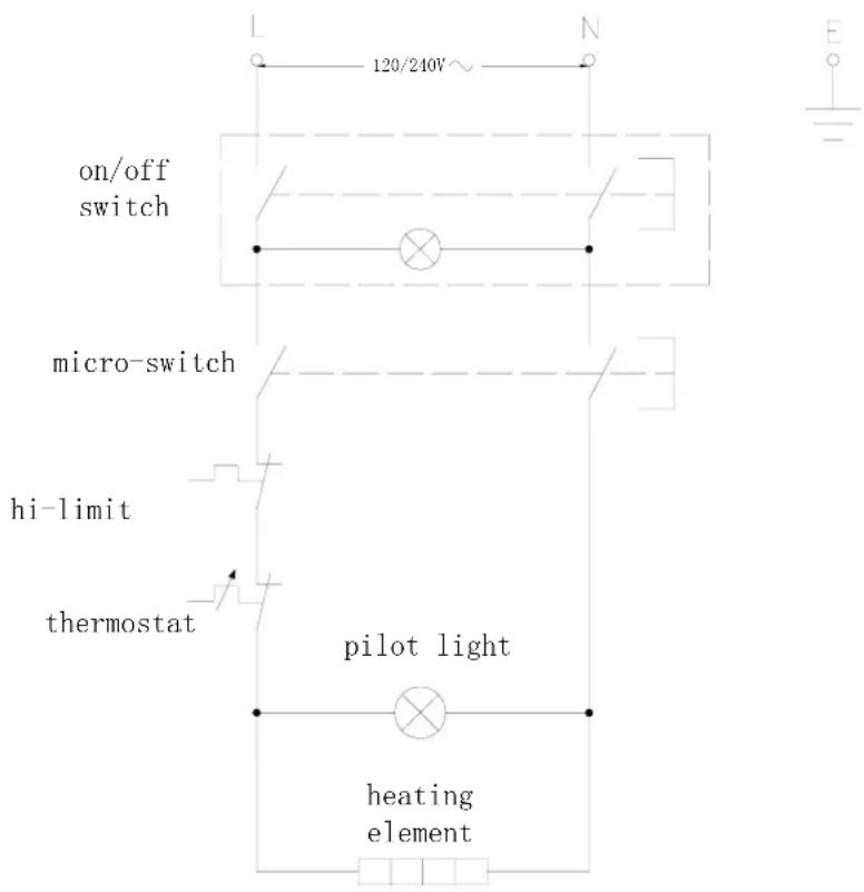
The above circuit diagram has been provided to assist qualified technicians. Cecilware agents or Recommended Qualified Service Technicians should carry out repairs if needed. Do not remove any components or service panels on this product.
Explosion View
EL-6

EL - 15/EL -25

EL - 2 x6
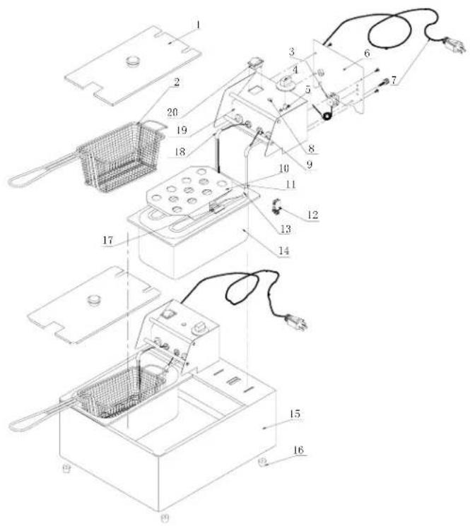
EL - 2 x15/EL - 2 x25

Spare Parts List
| EL-6 | EL-2x6 | EL-15 120vEL-25 240v | EL-2x15 120vEL-2x25 240v | ||||||
| NO | Description | Qty | Part No | Qty | Part No | Qty | Part No | Qty | Part No |
| 1 | Optional Fry Tank Cover 1 | 08049 | 2 08049 | 1 08 | 020 2 08 | 020 | |||
| 2 | Basket | 1 | 08050 | 2 | |||||
| 3 | Hi-Limit | 1 08 | 025 2 08 | 025 1 | 08050 2 | 08025 | |||
| 4 | Thermostat Dial | 1 08 | 026 2 08 | 026 1 | 08026 2 | 08026 | |||
| 5 | Thermostat | 1 | 08027 | 2 | 08027 | 1 | 08027 | 2 | 08027 |
| 6 | Back Plate | 1 | NA | 2 | NA | 1 | NA | 2 | NA |
| 7 | Cord & Plug-120 v | 1 | 08055 | 2 | 08055 | 1 | 08055 | 2 | 08055 |
| Cord & Plug-240 v | NA | NA | NA | NA | 1 | 08047 | 2 | 08047 | |
| 8 | Pilot Light-120 v | 1 | 08032 | 2 | 08032 | 1 | 08032 | 2 | 08032 |
| Pilot Light-240 v | NA | NA | NA | NA | 1 | 08067 | 2 | 08067 | |
| 9 | Stuffing Box | 2 | NA | 4 | NA | 2 | NA | 4 | NA |
| 10 | Element Cover | 1 | NA | 2 | NA | 1 | NA | 2 | NA |
| 11 | Heating Element-120 v | 1 | 08051 | 2 | 08051 | 1 | 08034 | 2 | 08034 |
| Heating Element-240 v | NA | NA | NA | NA | 1 | 08046 | 2 | 08046 | |
| 12 | Micro Switch | 1 08 | 029 2 08 | 029 1 | 08029 2 | 08029 | |||
| 13 | Bulb Clamp 2 | 2 08 | 030 4 08 | 030 2 | 08030 4 | 08030 | |||
| 14 | Fry Tank | 1 | 08052 | 2 | 08052 | 1 | 08022 | 2 | 08022 |
| 15 | Main Body | 1 | NA | 1 | NA | 1 | NA | 1 | NA |
| 16 | Feet | 4 | 08031 | 4 | 08031 | 4 | 08031 | 4 | 08031 |
| 17 | Tube Clamp-120 v | 2 | 08053 | 4 | 08053 | 2 | 08023 | 4 | 08023 |
| Tube Clamp-240 v | NA | NA | NA | NA | 2 | 08053 | 4 | 08053 | |
| 18 | Bulb Clamp 1 | 2 08 | 033 4 08 | 033 2 | 08033 4 | 08033 | |||
| 19 | Electrical Head | 1 | NA | 2 | NA | 1 | NA | 2 | NA |
| 20 | On/Off Switch-120 v | 1 | 08054 | 2 | 08054 | 1 | 08054 | 2 | 08054 |
| On/Off Switch-240 v | NA | NA | NA | NA | 1 | 08024 | 2 | 08024 | |
*NA = not available except by special order.
| MODEL | FAT CAPACITY | DESCRIPTION | ELECTRICAL | DIMENSIONS (WxDxH) |
| EL-6 | 6 | Ibs. | 120V, 1.8KW, 15A | 7 1/2"x171/2"x12 3/4" |
| EL-15 | 15 | BINGLE TANK | 11"x171/2"x15 3/4" | |
| EL-25 | 15 | Ibs. | 240V, 3.2KW, 15A | 11"x171/2"x15 3/4" |
| EL-2x6 (2x) | 6 Ibs. | Ibs. TWIN TANK | 120V, (2x)1.8KW, (2x)15A | 141/2"x171/2"x12 3/4" |
| EL-2x15 | (2x)15 | 21 3/4"x171/2" x15 3/4" | ||
| EL-2x25 | (2x)15 | Ibs. | 240V, (2x)3.2KW, (2x)15A | 21 3/4"x171/2" x15 3/4" |

CECILWARE CORPORATION
43-05 20 ^th AVENUE, LONG ISLAND CITY, NEW YORK 11105-1295 ■
718-932-1414
FAX 718-932-7860
www.cecilware.com

Brand : Cecilware
Model : EL-25
Category : Deep fryer