
D4 102 - Label printer CUSTOM - Free user manual and instructions
Find the device manual for free D4 102 CUSTOM in PDF.


| Product Type | Label Printer |
| Model | D4 102 |
| Brand | CUSTOM |
| Dimensions (W x L x H) | 200.00 mm x 263.19 mm x 188.29 mm |
| Weight | 2000 g |
| Power Supply | Input: 100-240 VAC, 50-60 Hz; Output: 24 VDC, 2.5 A, 60 W |
| Print Resolution | 203 dpi (300 dpi optional) |
| Print Method | Direct Thermal / Thermal Transfer |
| Print Speed | Up to 5 ips (203 dpi) / 4 ips (300 dpi) |
| Max Print Width | 104 mm |
| Max Print Length | 3810 mm |
| Interfaces | USB B (slave), Ethernet (optional) |
| Control Panel | 1 multi-functional key + 1 LED (Red, Blue, Purple) |
| Display | None (LED indicators only) |
| Memory | RAM: 64 MB SDRAM; ROM: 128 MB Flash |
| Media Types | Continuous, die-cut, tag, fan-fold, black mark labels |
| Max Label Width | 110 mm |
| Max Roll Diameter | 127 mm |
| Ribbon | Max 100 m length, 25.4-110 mm width, ID 12.7 mm; Wax, wax/resin, resin |
| Supported Barcodes | Code39, Code128, EAN13, UPC, Data Matrix, QR Code, PDF417, and more |
| Operating Temperature | -10°C to +60°C |
| Operating Humidity | 10% to 85% (non-condensing) |
| Safety & Compliance | CE, EMC (2014/30/EU), Low Voltage (2014/35/EU) |
| Accessories (optional) | Peeler module, cutter module |
Frequently Asked Questions - D4 102 CUSTOM
User questions about D4 102 CUSTOM
0 question about this device. Answer the ones you know or ask your own.
Ask a new question about this device
Download the instructions for your Label printer in PDF format for free! Find your manual D4 102 - CUSTOM and take your electronic device back in hand. On this page are published all the documents necessary for the use of your device. D4 102 by CUSTOM.
USER MANUAL D4 102 CUSTOM
Customer Service Department: www.custom4u.it
© 2020 CUSTOM S.p.A. – Italy.
All rights reserved. Total or partial reproduction of this manual in whatever form, whether by printed or electronic means, is forbidden. While guaranteeing that the information contained in it has been carefully checked, CUSTOM S.p.A. and other entities utilized in the realization of this manual bear no responsibility for how the manual is used. Information regarding any errors found in it or suggestions on how it could be improved are appreciated. Since products are subject to continuous check and improvement, CUSTOM S.p.A. reserves the right to make changes in information contained in this manual without prior notification.
The pre-installed multimedia contents are protected from Copyright CUSTOM S.p.A. Other company and product names mentioned herein may be trademarks of their respective companies. Mention of third-party products is for informational purposes only and constitutes neither an endorsement nor a recommendation. CUSTOM S.p.A. assumes no responsibility with regard to the performance or use of these products.
THE IMAGES USED IN THIS MANUAL ARE USED AS AN ILLUSTRATIVE EXAMPLES. THEY COULDN'T REPRODUCE THE DESCRIBED MODEL FAITHFULLY.
UNLESS OTHERWISE SPECIFIED, THE INFORMATION GIVEN IN THIS MANUAL
ARE REFERRED TO ALL MODELS IN PRODUCTION AT THE ISSUE DATE OF THIS DOCUMENT.
GENERAL INSTRUCTIONS
CUSTOM S.p.A. declines all responsibility for accidents or damage to persons or property occurring as a result of tampering, structural or functional modifications, unsuitable or incorrect installations, environments not in keeping with the equipment's protection degree or with the required temperature and humidity conditions, failure to carry out maintenance and periodical inspections and poor repair work.
GENERAL SAFETY INFORMATION
Your attention is drawn to the following actions that could compromise the characteristics of the product:
- Read and retain the instructions which follow.
- Follow all indications and instructions given on the device.
- Make sure that the surface on which the device rests is stable. If it is not, the device could fall, seriously damaging it.
- Make sure that the device rests on a hard (non-padded) surface and that there is sufficient ventilation.
- Do not fix indissolubly the device or its accessories such as power supplies unless specifically provided in this manual.
- When positioning the device, make sure cables do not get damaged.
- [Only OEM equipment] The equipment must be installed in a kiosk or system that provides mechanical, electrical and fire protection.
- The mains power supply must comply with the rules in force in the Country where you intend to install the equipment.
- Make sure that there is an easily-accessible outlet with a capacity of no less than 10A closely to where the device is to be installed.
- Make sure the power cable provided with the appliance, or that you intend to use is suitable with the wall socket available in the system.
- Make sure the electrical system that supplies power to the device is equipped with a ground wire and is protected by a differential switch.
- Before any type of work is done on the machine, disconnect the power supply.
- Use the type of electrical power supply indicated on the device label.
- These devices are intended to be powered by a separately certified power module ing an SELV, non-energy hazardous output. (IEC60950-1 second edition).
- [Only POS equipment] The energy to the equipment must be provided by power supply approved by CUSTOM S.p.A.
• Take care the operating temperature range of equipment and its ancillary components.
- Do not block the ventilation openings.
- Do not insert objects inside the device as this could cause short-circuiting or damage components that could jeopardize printer functioning.
- Do not carry out repairs on the device yourself, except for the normal maintenance operations given in the user manual.
- The equipment must be accessible on these components only to trained, authorized personnel.
- Periodically perform scheduled maintenance on the device to avoid dirt build-up that could compromise the correct, safe operation of the unit.
- Do not touch the head heating line with bare hands or metal objects. Do not perform any operation inside the printer immediately after printing because the head and motor tend to become very hot.
- Use consumables approved by CUSTOM S.p.A.

THE CE MARK AFFIXED TO THE PRODUCT CERTIFY THAT THE PRODUCT SATISFIES THE BASIC SAFETY REQUIREMENTS.
The device is in conformity with the essential Electromagnetic Compatibility and Electric Safety requirements laid down in Directives 2014/30/EU and 2014/35/EU inasmuch as it was designed in conformity with the provisions laid down in the following Standards:
• EN 55032 (Limits and methods of measurements of radio disturbance characteristics of Information Technology Equipment)
- EN 55024 (Information Technology Equipment – Immunity characteristics – Limits and methods of measurement)
• EN 60950-1 (Safety of information equipment including electrical business equipment)
The device is in conformity with the essential requirements laid down in Directives 2014/53/EU about devices equipped with intentional radiators The Declaration of Conformity and other available certifications can be downloaded from the site www.custom4u.it.

GUIDELINES FOR THE DISPOSAL OF THE PRODUCT
The crossed-out rubbish bin logo means that used electrical and electronic products shall NOT be mixed with unsorted municipal waste. For more detailed information about recycling of this product, refer to the instructions of your country for the disposal of these products.
- Do not dispose of this equipment as miscellaneous solid municipal waste, but arrange to have it collected separately.
- The re-use or correct recycling of the electronic and electrical equipment (EEE) is important in order to protect the environment and the wellbeing of humans.
- In accordance with European Directive WEEE 2012/19/EU, special collection points are available to which to deliver waste electrical and electronic equipment and the equipment can also be handed over to a distributor at the moment of purchasing a new equivalent type.
- The public administration and producers of electrical and electronic equipment are involved in facilitating the processes of the re-use and recovery of waste electrical and electronic equipment through the organisation of collection activities and the use of appropriate planning arrangements.
- Unauthorised disposal of waste electrical and electronic equipment is punishable by law with the appropriate penalties.
TABLE OF CONTENTS
1 INTRODUCTION....7
2 IDENTIFICATION OF THE MODELS 9
3 DESCRIPTION....11
3.1 Box contents.... 1 1
3.2 Device components: external views 14
3.3 Connectors panel 17
3.4 Device components: internal view 19
3.5 Product label....20
3.6 Control panel 21
3.7 LCD screen icons 27
4 INSTALLATION....33
4.1 Connections 33
4.2 Pinout 35
4.3 Driver and SDK....39
5 OPERATION 41
5.1 Opening the top cover 41
5.2 Opening the ribbon compartment cover 42
5.3 Opening the frontal cover 44
5.4 Switch the device on....47
5.5 Loading the ribbon roll 48
5.6 Loading the ribbon label roll 52
6 MAINTENANCE 55
6.1 Planning of cleaning operations ....55
6.2 Cleaning 56
7 STANDALONE OPERATION D4 102....59
8 STANDALONE OPERATION D4 202 AND D4 302-K....63
8.1 Description of keyboard 63
8.2 Instruction guide of SD card 74
8.3 Check out printing records 76
8.4 Download firmware....77
8.5 Files converter (from frm. to frs.) 79
9 SPECIFICATIONS 83
9.1 Hardware specifications 83
10 ACCESSORIES 87
11 TECHNICAL SERVICE 89
1 INTRODUCTION
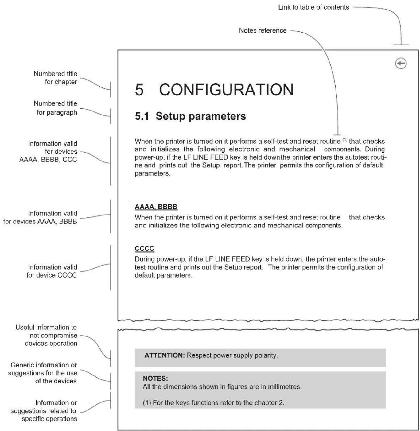
This document is divided into sections and chapters. Each chapter can be reached by the index at the beginning of this document. The index can be reached by the button on each page as shown in the diagram below.
2 IDENTIFICATION OF THE MODELS
NOMENCLATURE DESCRIPTION
D4 102 LABEL PRINTER D4 102 USB
D4 202 LABEL PRINTER D4 202 USB RS232
D4 302-K LABEL PRINTER D4 302-K USB RS232
3 DESCRIPTION
3.1 Box contents
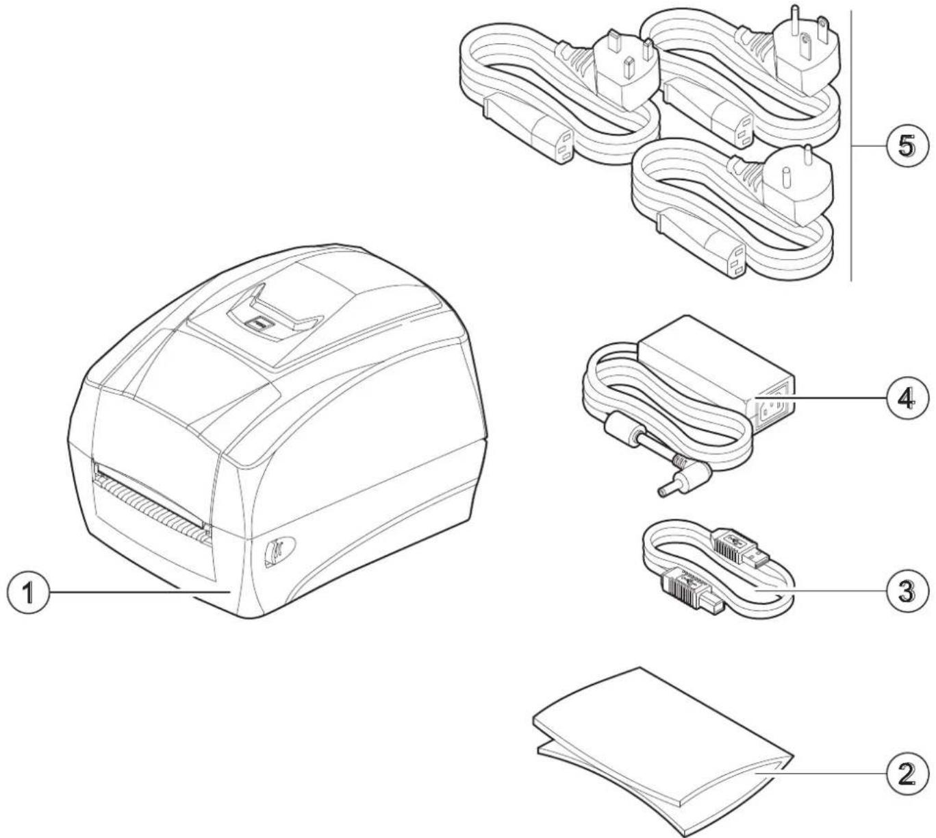
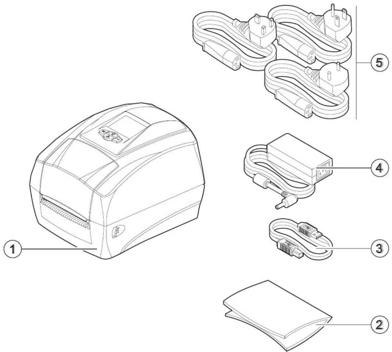
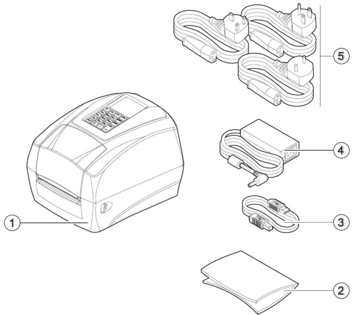
Remove all the box contents (see following figures) being careful not to damage the packing material so that it may be re-used if the device is to be transported in the future.
Make sure that all the components illustrated below are present and that there are no signs of damage. If there are, contact customer service.
D4 102
- Device
- Documentation (Short guide, warranty sheet)
- USB cable
- Power supply
- Power supply cable
D4 202
- Device
- Documentation (Short guide, warranty sheet)
- USB cable
- Power supply
- Power supply cable
D4 302-K
- Device
- Documentation (Short guide, warranty sheet)
- USB cable
- Power supply
- Power supply cable
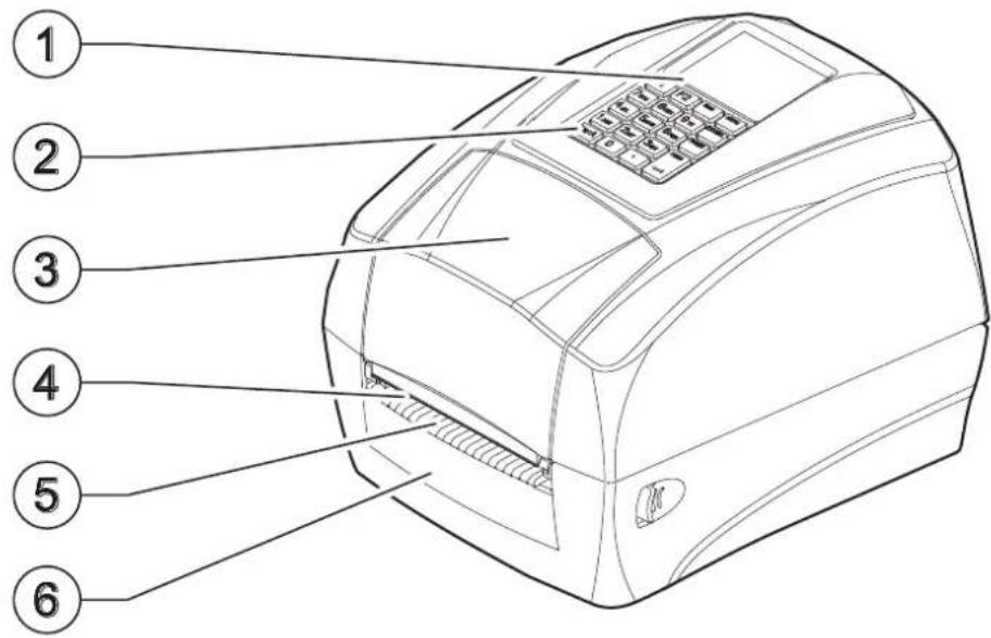
3.2 Device components: external views
D4 102
- LED status
- Control panel
- Ribbon compartment cover
- Tear off blade
- Paper output
- Front cover
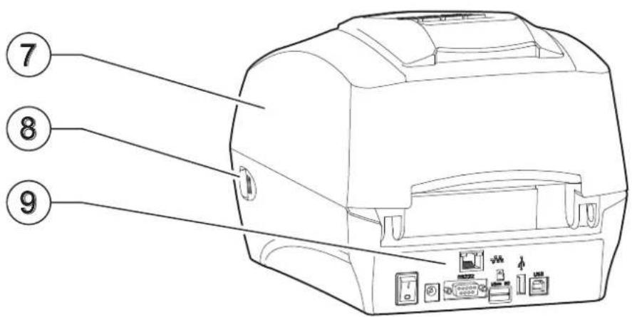
- Top cover
- Release latch (x2)
- Connectors panel
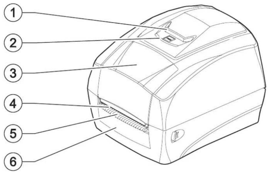
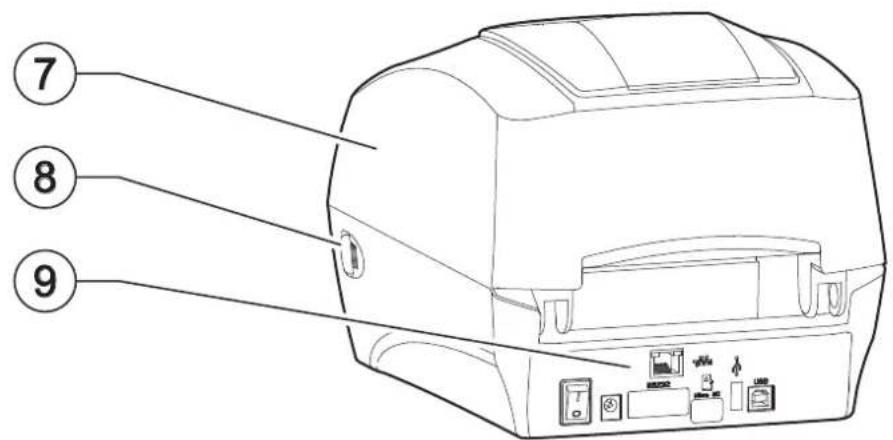
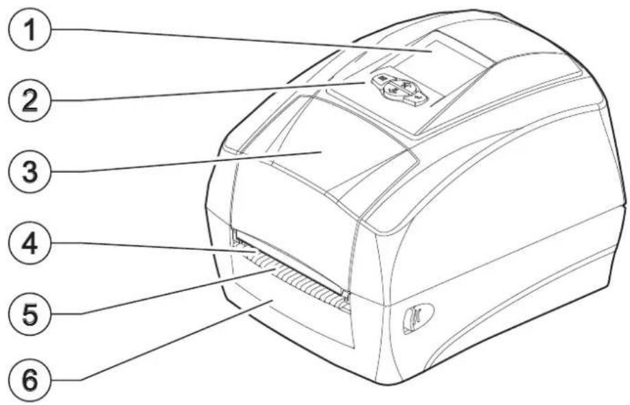
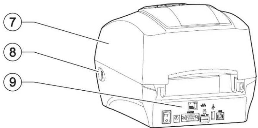
D4 202
- LCD screen
- Control panel
- Ribbon compartment cover
- Tear off blade
- Paper output
- Front cover
- Top cover
- Release latch (x2)
- Connectors panel
D4 302-K
- LCD screen
- Control panel
- Ribbon compartment cover
- Tear off blade
- Paper output
- Front cover
- Top cover
- Release latch (x2)
- Connectors panel
3.3 Connectors panel
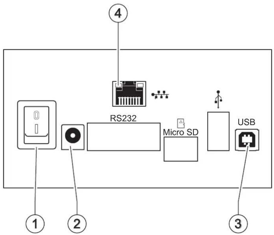
D4 102
- ON/OFF key
- Power supply port
- USB B Port
- Ethernet port (optional)
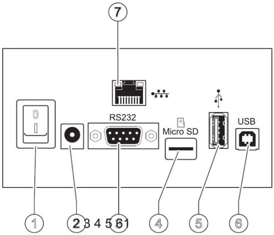
D4 202, D4 302-K
- ON/OFF key
- Power supply port
- RS232 port
- MicroSD port
- USB A port
- USB B Port
- Ethernet port (optional)
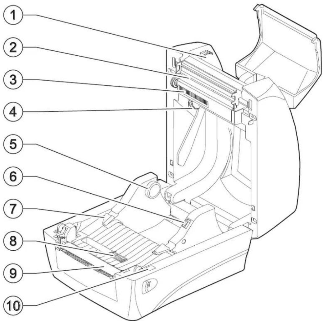
3.4 Device components: internal view
D4 102, D4 202, D4 302-K
- Grear wheel of the empty media core
- Printhead
- Ribbon label sensor
- Grear wheel of the ribbon roll
-
Holder for ribbon label roll (x2)
-
Holder latch
- Guides (x2)
- Gap, notch or black mark movable sensor
- Platen roller
- Top cover sensor
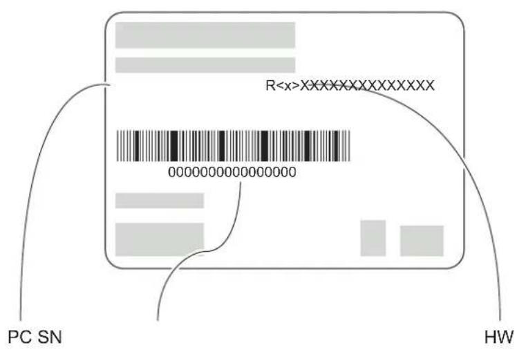
3.5 Product label
PC = Product code (14 digits)
SN = Serial number
HW = Hardware release
3.6 Control panel
D4 102
The key functions are available under the device Ready mode.
GRAPHIC SYMBOL STATUS LED DESCRIPTION
FEED
GREEN LIGHT
Press once for feed a blank label
FEED
YELLOW LIGHT
Press for 2 seconds for label calibration.
FEED
GREEN LIGHT
Press for 4 seconds for print self test page.
FEED
YELLOW LIGHT RAPIDLY FLASHING
Press 9 seconds to return for the factory default.
The key functions are available under the device Printing mode.
GRAPHIC SYMBOL STATUS LED DESCRIPTION
FEED
GREEN LIGHT
Press once for pause/restart printing.
FEED
GREEN LIGHT
Press for 3 seconds for cancel.
The key functions are available under the device Auto form mode.
GRAPHIC SYMBOL STATUS LED DESCRIPTION
FEED
YELLOW LIGHT
Continuously press when turning on the printer for cancel the auto form.
Status LED.
| STATUS LED DESCRIPTION | |
| FLASH IN RED LIGHT | Label out.Ribbon out.Cover open.Label gap out. |
| FLASH IN GREEN LIGHT | Pause.Rapidly flash when receiving. |
| BLUE LIGHT AFTER YELLOW LIGHT Print self test page. | |
| CONSTANTLY FLASH IN YELLOW LIGHT Auto form mode. | |
| RAPIDLY FLASH IN YELLOW LIGHT Reset to factory default. | |
D4 202
The key functions are available under the device Ready mode.
GRAPHIC SYMBOL FUNCTION DESCRIPTION

MENU Enter the menu list to setup the printer configuration.

FEED Feed a blank label.
The key functions are available under the device Printing mode.
GRAPHIC SYMBOL FUNCTION DESCRIPTION
CANCEL
Stop and cancel the current printing job. Removes the error status when problem is resolved.

PAUSE Stop and restart the printing process.
The key functions are available in Menu mode.
GRAPHIC SYMBOL FUNCTION DESCRIPTION
RETURN Return back to previous menu level.

UP
Scroll up the menu options. Increase the parameter values.

DOWN
Scroll down the menu options. Decrease the parameter values.
ENTER Confirm the selected option.
The key functions are available in Labelless calibration mode.
GRAPHIC SYMBOL FUNCTION DESCRIPTION

MENU Return back to previous menu level.
CANCEL Calibrate with ribbon.

PAUSE Calibrate without ribbon.
FEED Normal mode.
The key functions are available under the device Ready mode.
GRAPHIC SYMBOL FUNCTION DESCRIPTION

MENU Enter the menu list to setup the printer configuration.
FEED Allow to feed a blank label.
The key functions are available under the device Printing mode.
GRAPHIC SYMBOL FUNCTION DESCRIPTION

CANCEL
Stop and cancel the current printing job. Removes the error status when problem is resolved.

PAUSE Stop and restart the printing process.
The key functions are available in Menu mode.
GRAPHIC SYMBOL FUNCTION DESCRIPTION

RETURN Return back to previous menu level.

UP
Scroll up the menu options. Increase the parameter values.

DOWN
Scroll down the menu options. Decrease the parameter values.
ENTER Confirm the selected option.
The key functions are available in Labelless calibration mode.
GRAPHIC SYMBOL FUNCTION DESCRIPTION

MENU Return back to previous menu level.

CANCEL Calibrate with ribbon.

PAUSE Calibrate without ribbon.
FEED Normal mode.
3.7 LCD screen icons
D4 202, D4 302-K
LCD screen information consists 4 parts to show the Printer status.
- Device status (when printer is in Ready status)
- Time and setting icon
- Printer current status and setting level
- Keys status bar
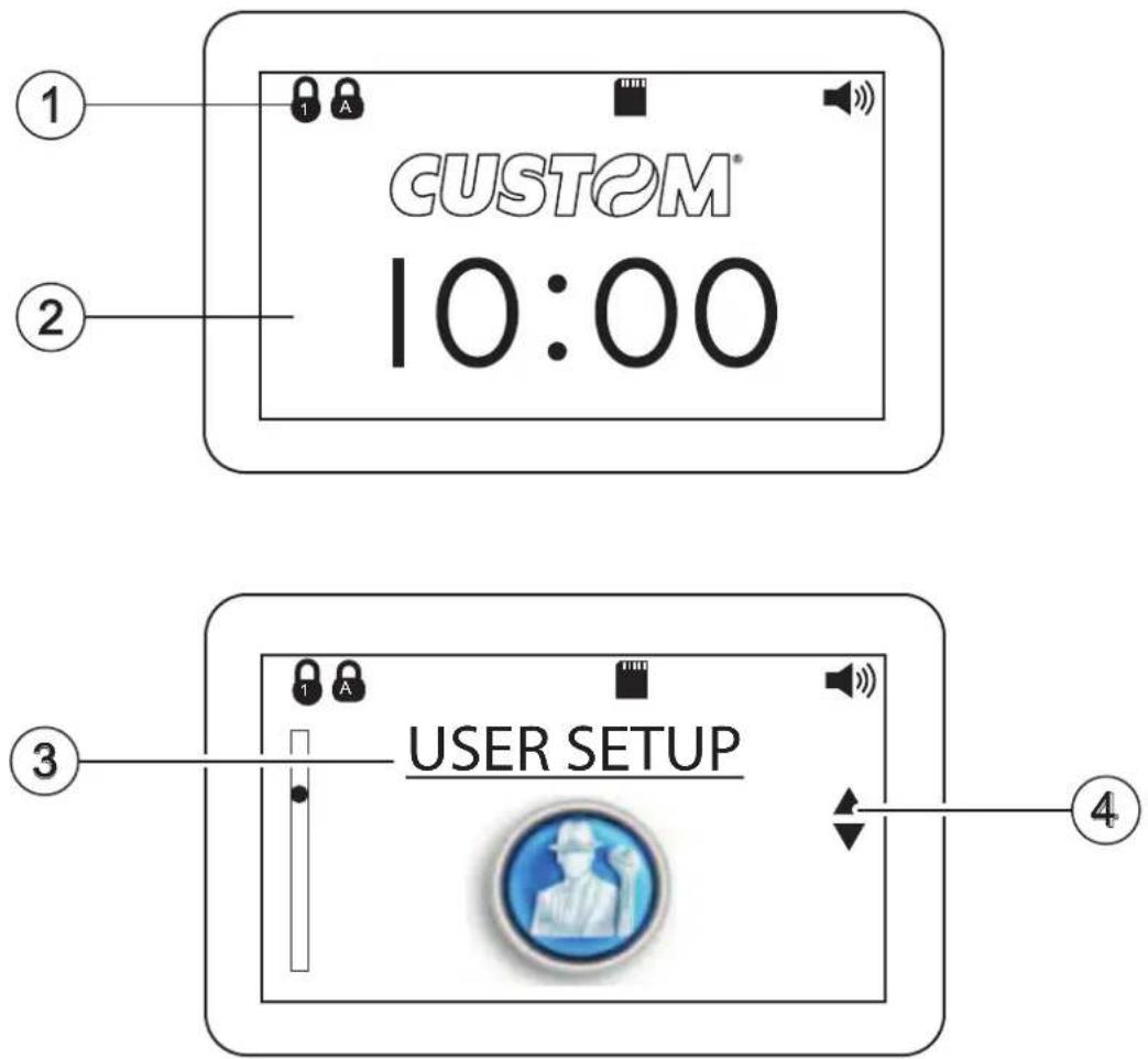
Device status bar.
GRAPHIC SYMBOL FUNCTION DESCRIPTION

BUZZER ON Buzzer symbol will be shown when buzzer is set to on.

SD CARD INSERTED SD card symbol will be shown when SD card is inserted.

USB MASTER INTERFACE (keyboard or scanner) INSERTED USB master symbol will be shown when interface is inserted.

SCROLL UP
Key status bar: the symbol will be shown on the Key status bar when the key function is available.

SCROLL DOWN
Key status bar: the symbol will be shown on the Key status bar when the key function is available.
Menu structure.
GRAPHIC SYMBOL FUNCTION DESCRIPTION

INFORMATION Printer configuration information.

USER SETUP
LANGUAGE Change menu language.

LCD CONTRAST Contrast of LCD.
BUZZER VOLUME Adjust the buzzer volume.
DATE Set the RTC Date.

TIME Set the RTC time.

DEFAULT Initiate to factory default.
PASSWORD
Set the password to lock the change of parameter.
COMM. SETUP
RS-232 Set RS-232 parameter.
ETHERNET
Ethernet status and set configuration.
PRINT SETUP

TRANSFER MODE Thermal transfer or thermal direct.
PRINT MODE Set to peeler, cutter or tear off function.

SPEED Printing speed.
DARKNESS Printing heat value.
LABEL TYPE Select the label type.
GAP SENSOR Select label sensor type.
 | PRINT WIDTH Set the print width. | |
 | PRINT X OFFS | Adjust the origin of printer horizontal coordinate. |
 | PRINT Y OFFS | Adjust the origin of printer vertical coordinate. |
 | TPH Y OFFS Set the print head vertical offset. | |
 | BACK Y OFFS | Set the label stop position for peeler, cutter or tear-off mode. |
 | ERROR REPRINT | Reprint the previous label when error occurs. |
 | CANCEL MODE Stop printing the current job. | |

TEST

 | LABELLESS CALIBRATION | Calibrate with/without label. | |
 | MEMORY | ||
 | FREE SIZE | Show the free memory size in Flash and SD card. | |
 | LIST | List the forms, images and fonts in memory device. | |
 | DELETE FILES | Delete separately the stored forms, images and fonts in memory. | |
 | CLEAR MEMORY | Delete all stored forms, images and fonts in the memory. | |
 | FORM | ||
 | RUN THE FORM | Execute the stored form in memory. | |
 | AUTO FORM | Execute automatically the selected form as the printer is power on. | |
 | F/W UPDATE | Update firmware directly ROM the SD card. | |
4 INSTALLATION
4.1 Connections
The following figure shows the possible connections for the device. .
D4 102
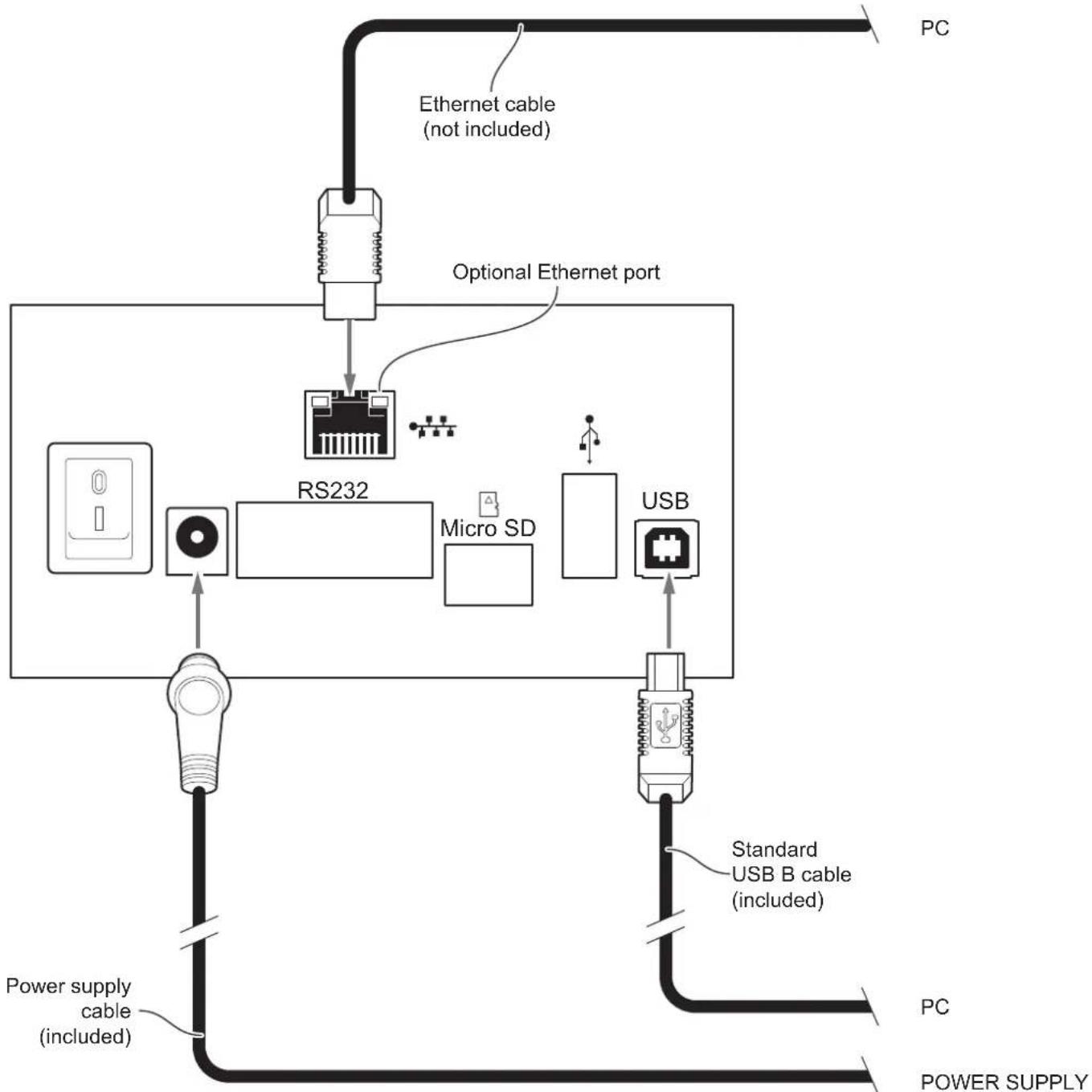
flowchart
graph TD
    A["Power supply cable (included)"] --> B["RS232"]
    C["Power supply cable (included)"] --> B
    D["PC"] --> E["Optional Ethernet port"]
    F["Micro SD"] --> B
    G["USB"] --> H["Standard USB B cable (included)"]
    I["Ethernet cable (not included)"] --> B
    J["PC"] --> K["Power Supply"]
    L["PSB"] --> M["RS232"]
D4 202, D4 302-K
When the RS232 and USB communication cables are connected to the device at the same time, the communication take place via the USB port.
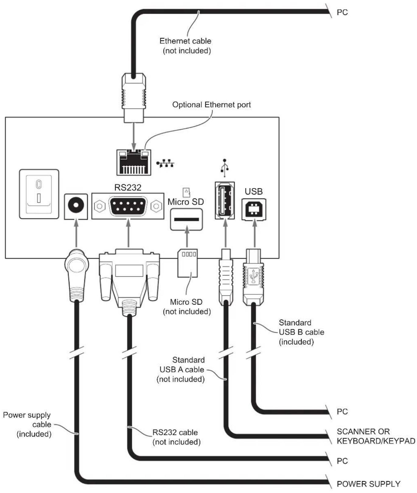
flowchart
graph TD
    A["Power supply cable (included)"] --> B["RS232"]
    B --> C["Micro SD (not included)"]
    C --> D["RS232"]
    D --> E["Micro SD (not included)"]
    E --> F["USB"]
    F --> G["USB"]
    G --> H["PC"]
    G --> I["PC"]
    G --> J["PC"]
    G --> K["PC"]
    G --> L["PC"]
    G --> M["PC"]
    G --> N["PC"]
    G --> O["PC"]
    G --> P["PC"]
    G --> Q["PC"]
    G --> R["PC"]
    G --> S["PC"]
    G --> T["PC"]
    G --> U["PC"]
    G --> V["PC"]
    G --> W["PC"]
    G --> X["PC"]
    G --> Y["PC"]
    G --> Z["PC"]
    G --> AA["PC"]
    G --> AB["PC"]
    G --> AC["PC"]
    G --> AD["PC"]
    G --> AE["PC"]
    G --> AF["PC"]
    G --> AG["PC"]
    G --> AH["PC"]
    G --> AI["PC"]
    G --> AJ["PC"]
    G --> AK["PC"]
    G --> AL["PC"]
    G --> AM["PC"]
    G --> AN["PC"]
    G --> AO["PC"]
    G --> AP["PC"]
    G --> AQ["PC"]
    G --> AR["PC"]
    G --> AS["PC"]
    G --> AT["PC"]
    G --> AU["PC"]
    G --> AV["PC"]
    G --> AW["PC"]
    G --> AX["PC"]
    G --> AY["PC"]
    G --> AZ["PC"]
    G --> BA["PC"]
    G --> BB["PC"]
    G --> BC["PC"]
    G --> BD["PC"]
    G --> BE["PC"]
    G --> BF["PC"]
    G --> BG["PC"]
    G --> BH["PC"]
    G --> BI["PC"]
    G --> BJ["PC"]
    G --> BK["PC"]
    G --> BL["PC"]
    G --> BM["PC"]
    G --> BN["PC"]
    G --> BO["PC"]
    G --> BP["PC"]
    G --> BQ["PC"]
    G --> BR["PC"]
    G --> BS["PC"]
    G --> BT["PC"]
    G --> BU["PC"]
    G --> BV["PC"]
    G --> BW["PC"]
    G --> BX["PC"]
    G --> BY["PC"]
    G --> BZ["PC"]
    G --> CA["PC"]
    G --> CB["PC"]
    G --> CC["PC"]
    G --> CD["PC"]
    G --> CE["PC"]
    G --> CF["PC"]
    G --> CG["PC"]
    G --> CH["PC"]
    G --> CI["PC"]
    G --> CJ["PC"]
    G --> CK["PC"]
    G --> CR["PC"]
    G --> CS["PC"]
    G --> CT["PC"]
    G --> CU["PC"]
    G --> CV["PC"]
    G --> CW["PC"]
4.2 Pinout
D4 102, D4 202, D4 302-K
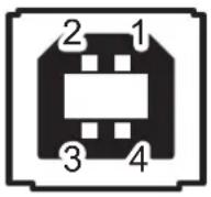
USB INTERFACE
Female USB type B connector
| 1 | JSB0_VBUS (in) | |
| 2 | JSB0_D- (in/out) | |
| 3 | JSB0_D+ (in/out) | |
| 4 | GND | |
| SH1 | SHIELD | |
| SH2 | SHIELD |
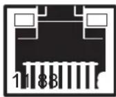
ETHERNET INTERFACE (Optional)
Female RJ45 connector
| 1 RX +1 |
| 2 +3.3V ETH |
| 3 RX -1 |
| 4 TX +1 |
| 5 +3.3V ETH |
| 6 TX -1 |
| 7 n.c |
| 8 GND |
| 9 +3.3 V |
| 10 LED-LNK |
| 11 +3.3 V |
| 12 LED-LAN |
| 13 Shield |
| 14 Shield |
NOTES:
The functionality of two LED are specified in the following tables:
| LED FUNCTION | |
| LED-LNK Link (yellow color): the LED lights up when a connection is active | |
| LED-LAN Rx | Tx: (green color): the LED lights up when occurs a data reception or transmission |
- For 10/100Base-TX connection:
| LED FUNCTION | |
| LED-LNK | The LED light (yellow color) on when a connection is active and flashes when occurs a data reception or transmission |
| LED-LAN The | LED light (green color) on when occurs a 100 Mbit connection and off when occurs a 10 Mbit connection |
The device automatically recognizes the type of connection (cross or pin-to-pin).
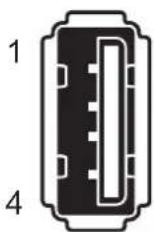
USB INTERFACE (D4 202/
Female USB type A connector
| 1 | VBUS-A (in) |
| 2 | HD- |
| 3 | HD+ |
| 4 | GND |
| SH1 | GND |
| SH2 | GND |
| SH3 | GND |
| SH4 | GND |
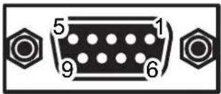
RS232 SERIAL INTERFACE
Female DB9 connector
| 1 | DTR |
| 2 | TX During transmission, takes the values -VRS232 and + VRS232 depending on data |
| 3 | RX During reception, takes the values -VRS232 and +VRS232 depending on data |
| 4 | DSR |
| 5 | GND |
| 6 | DTR When +VRS232, device is power on |
| 7 | CTS |
| 8 | RTS When +VRS232, device is ready to receive data |
| 9 | n.c. |
NOTES:
Given the presence of the RS232 standard, logic value "0" corresponds to the voltage value +VRS232 (voltage value between +3Vdc and +15Vdc) and logic value "1" corresponds to the voltage value -VRS232 (voltage value between -3Vdc and -15Vdc.
DEVICE > PC connection
The following picture shows an example of connection between the device and a personal computer using a 9 pin RS232 serial connector:
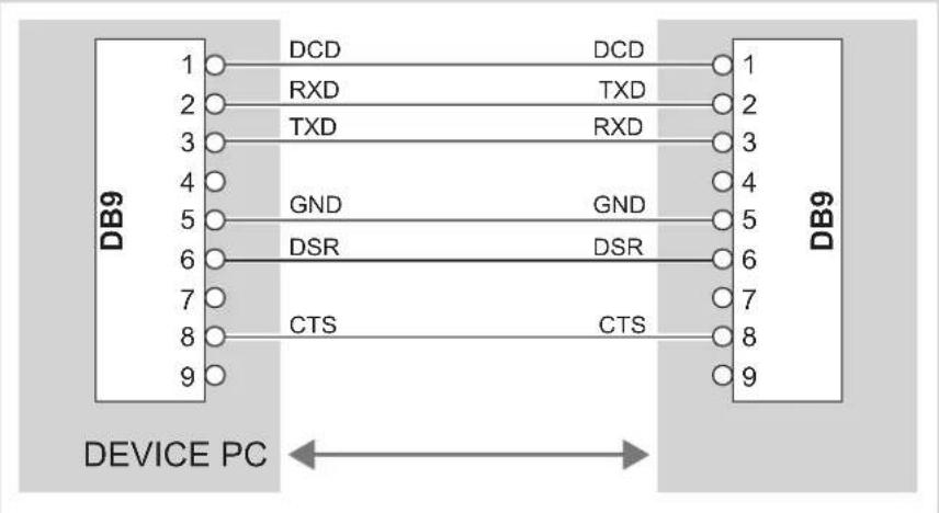
When use a serial cable, we recommend the installation of a ferrite core on the power supply cable.
4.3 Driver and SDK
In the website www.custom4u.it are available the drivers for the following operating system:
| OPERATING SYSTEM | DESCRIPTION INSTALLATION PROCEDURE | |
| Windows | Driver for Windows XP | From the Start menu, press Run and type-in the path where the SW was saved on PC, then click OK. Follow the instructions on the screen to install the driver. |
| Driver for Windows VISTA (32/64 bit) | ||
| Driver for Windows 7 (32/64 bit) | ||
| Driver for Windows 8 (32/64 bit) | ||
| Driver for Windows 8.1 (32/64 bit) | ||
| Driver for Windows 10 (32/64 bit) | ||
5 OPERATION
5.1 Opening the top cover
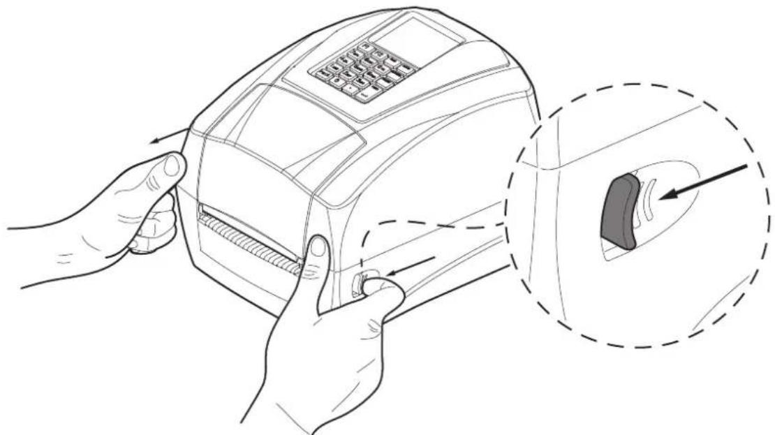
To open the top cover proceed as follows.
1
natural_image
Line drawing of hands inserting a payment card into a device, with an inset showing the internal component (no text or symbols present)Pull the release levers on both sides to unlock the cover.
2

natural_image
Technical line drawing of an open industrial machine with internal components and a warning symbol (no text or labels)Lift the top cover to the maximum opening position as shown in figure.
5.2 Opening the ribbon compartment cover
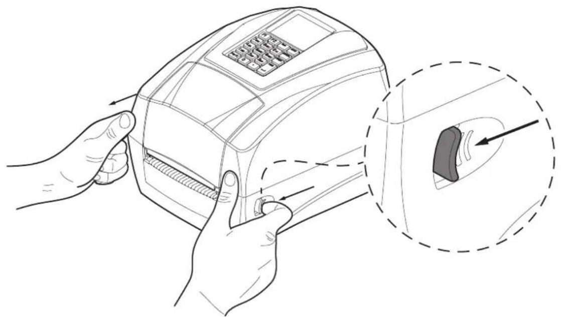
To open the ribbon compartment cover proceed as follows.
1
natural_image
Line drawing of a hand inserting a payment card into a device, with an inset showing the internal component (no text or symbols present)Pull the release levers on both sides to unlock the cover.
2
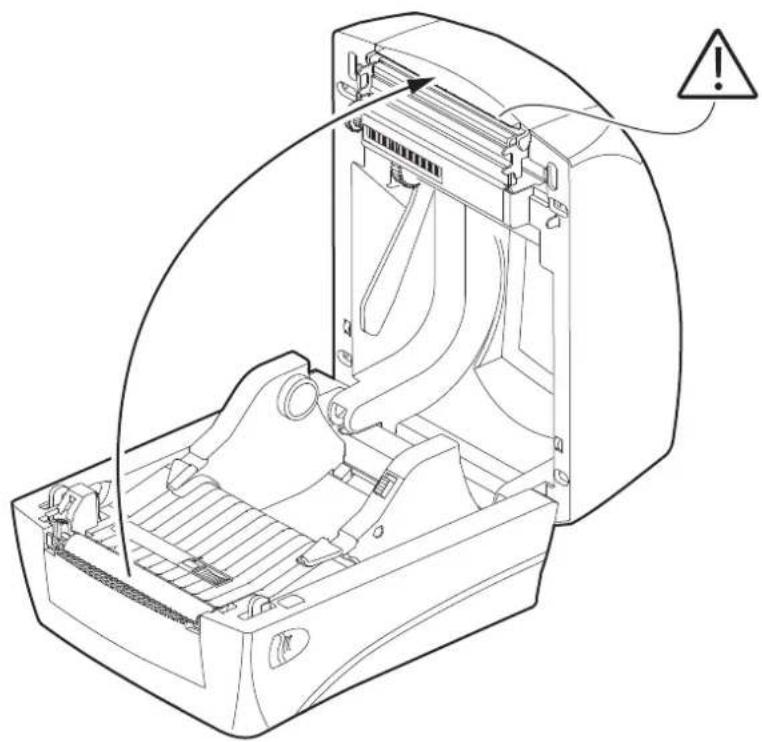
natural_image
Technical line drawing of an open computer case with a warning symbol indicating caution (no text or labels present)Lift the top cover to the maximum opening position as shown in figure.
3
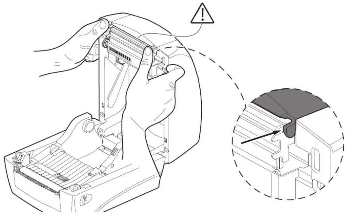
natural_image
Technical illustration of a mechanical device being adjusted for a component, with an inset showing a close-up of the internal structure (no text or symbols present)Press the levers as shown in the figure.
4
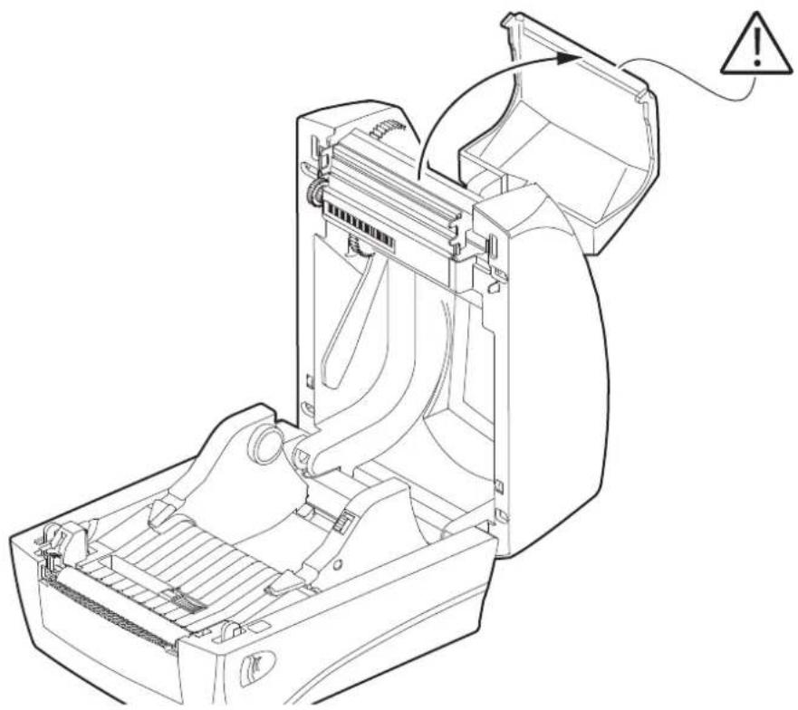
natural_image
Technical line drawing of a mechanical device interior with no visible text or symbolsLift the ribbon compartment cover to the maximum opening position as shown in figure.
5.3 Opening the frontal cover
To open the front cover proceed as follows.
1
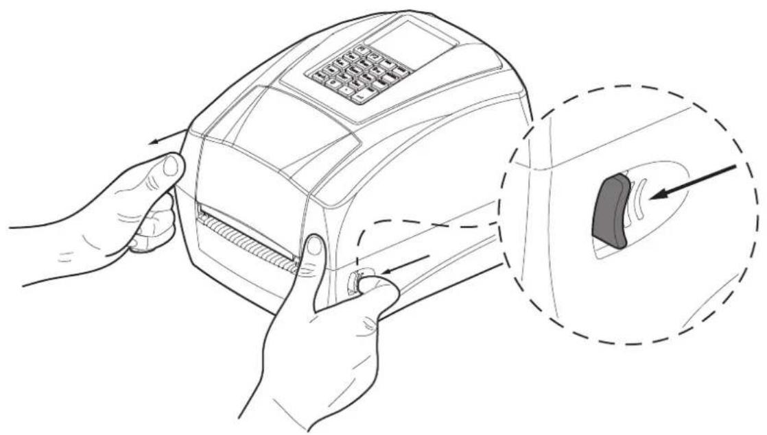
natural_image
Line drawing of hands inserting a payment terminal into a device, with an inset showing the close-up of the component (no text or symbols present)Pull the release levers on both sides to unlock the cover.
2
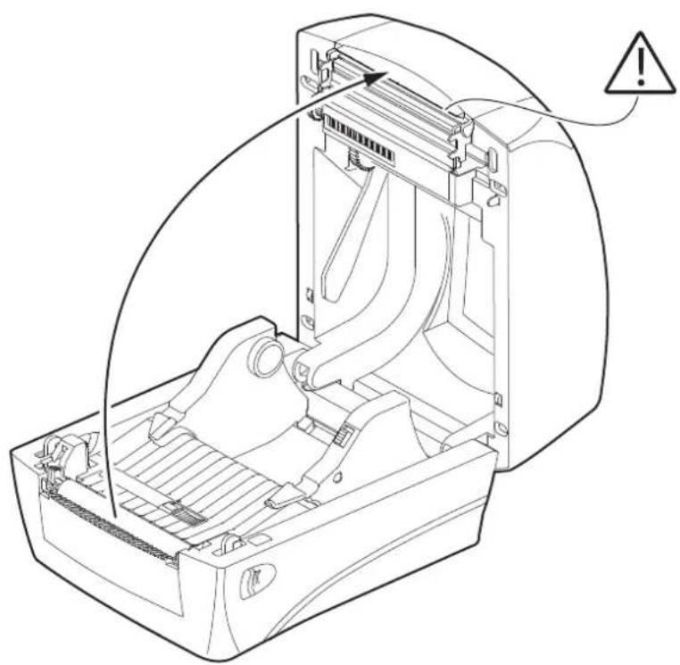
natural_image
Technical line drawing of an open computer case with a warning symbol indicating no text or labelsLift the top cover to the maximum opening position as shown in figure.
3
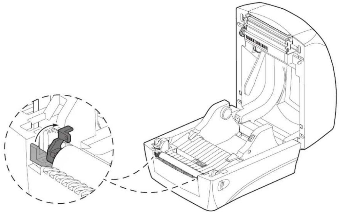
natural_image
Technical line drawing of a mechanical device with an inset showing a close-up of internal components (no text or symbols)Push the platen roller bearing tabs (one on the right, one on the left) upwards and rotate them backwards to the end.
4
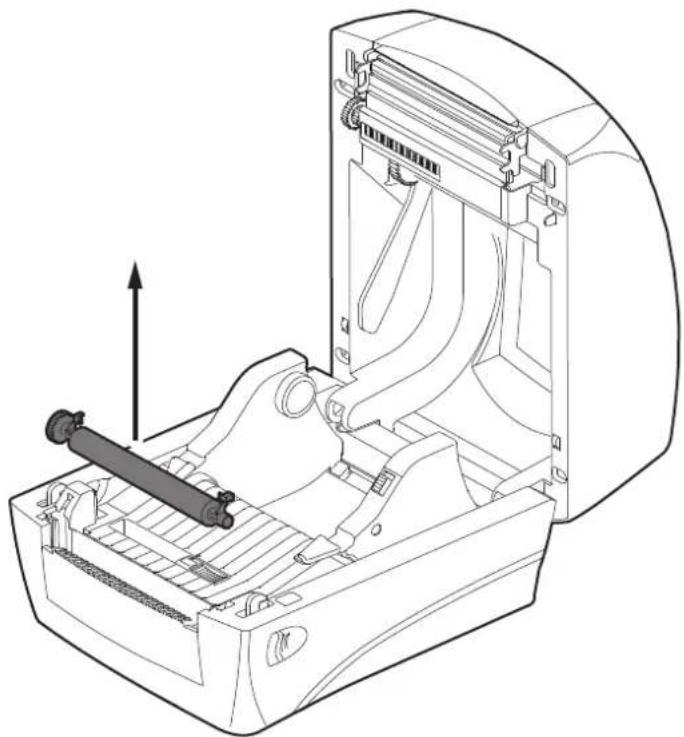
natural_image
Technical line drawing of a mechanical device with internal components and an upward arrow indicator (no text or symbols)Lift and remove the platen roller.
5
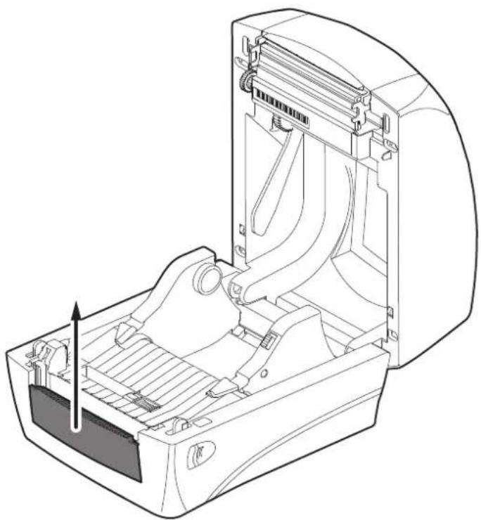
natural_image
Technical line drawing of an open industrial machine with internal components and a directional arrow indicating motion (no text or symbols)Lift and remove the front cover.
5.4 Switch the device on
To open turn on the device proceed as follows.
1
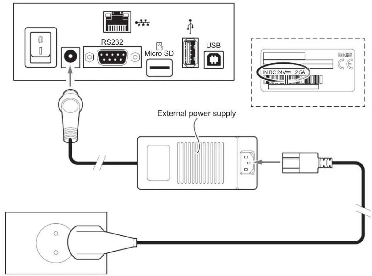
Connect the power supply adapter to the device and the mains outlet. Use the type of electrical power supply indicated on the device label.
2
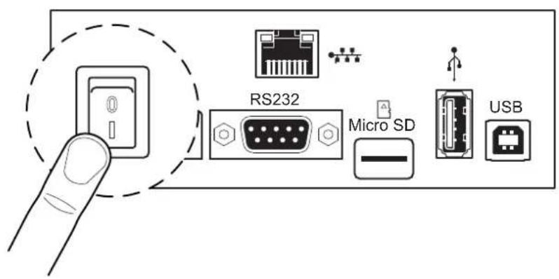
Locate the ON/OFF key in the right side.
5.5 Loading the ribbon roll
To load the ribbon roll into the device proceed as follows. At every change of paper, check inside the device to locate and remove any scraps of paper.
Only use approved paper rolls.
1
natural_image
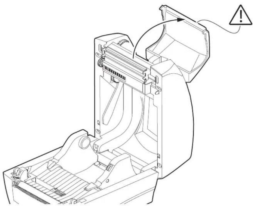
Technical line drawing of a mechanical device with internal components and an explosion warning symbol (no text or labels)2
Ribbon compartment cover opening see paragraph 5.1.
natural_image
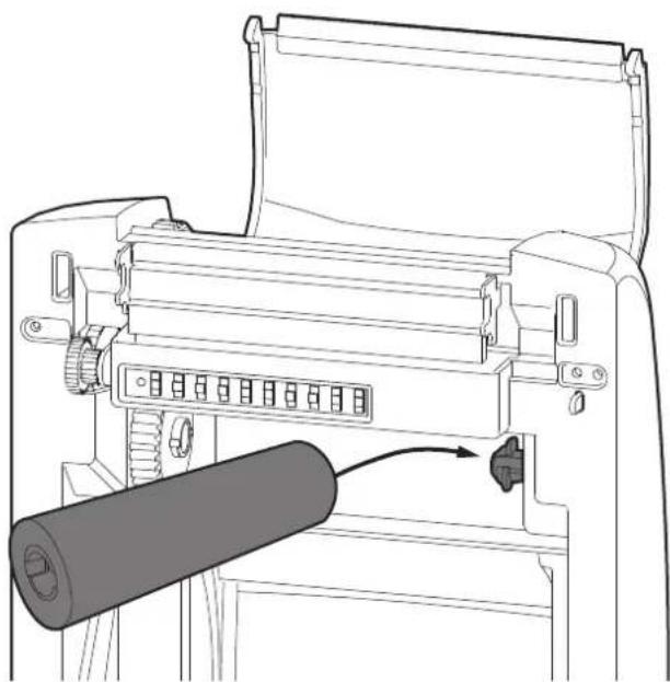
Line drawing of a printer holder with a cylindrical roller being inserted (no text or symbols)Insert the ribbon roll to the spindle.
3
natural_image
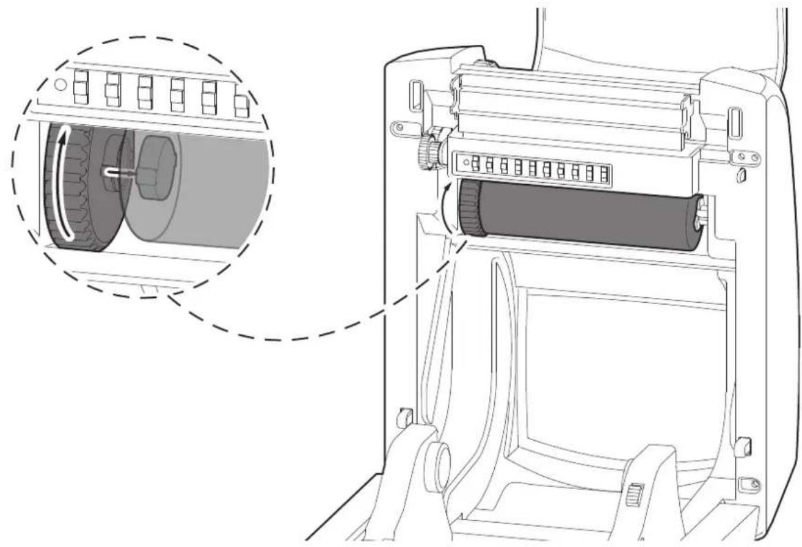
Technical line drawing of a mechanical device with a magnified inset showing internal components (no text or symbols)Rotate the grear wheel until the notches align and lock in to the left side of the ribbon roll.
4
natural_image
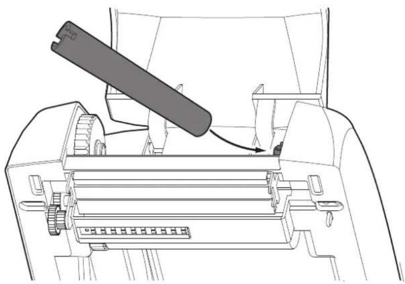
Technical line drawing of a mechanical component with a lever and adjustment mechanism (no text or symbols)Insert the empty media core into the take up spindle.
5
natural_image
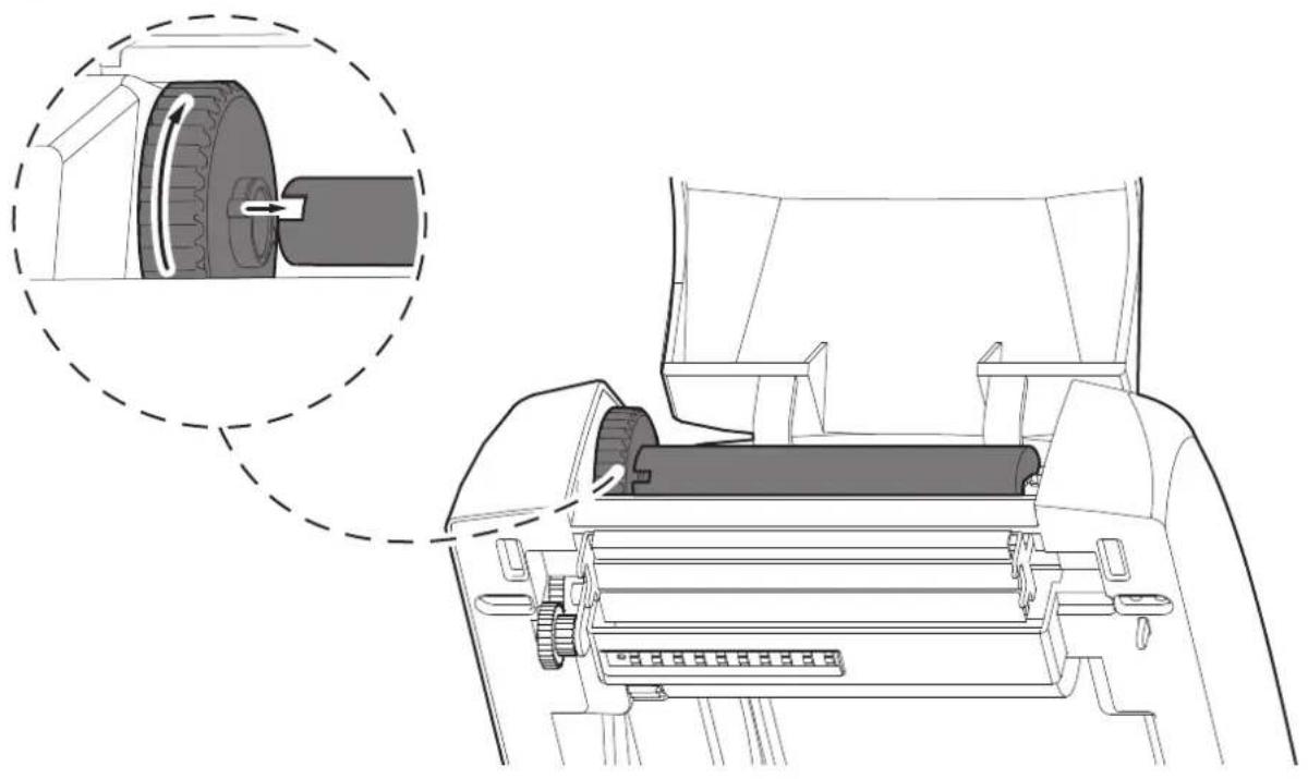
Technical line drawing of a vehicle engine component with a magnified inset showing the wheel assembly (no text or symbols)Rotate the grear wheel until the notches align and lock in to the left side of the empty media core.
6
natural_image
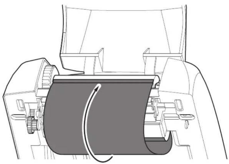
Technical line drawing of a mechanical component with internal gears and housing (no text or symbols)Pull the ribbon out from the ribbon roll and stick it with the adhesive tape on the empty media core take up.
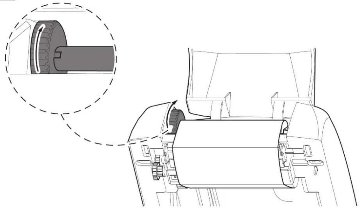
7
natural_image
Technical line drawing of a mechanical assembly with a magnified inset showing internal components (no text or symbols)Rotate the grear wheel on the left side of empty media core until the ribbon is pulled tight.
8
natural_image
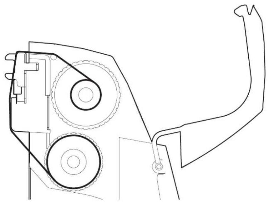
Technical line drawing of a mechanical device with gears and shafts (no text or symbols)The figure show a section of the device with the ribbon path (outside wound).
5.6 Loading the ribbon label roll
To load the label roll into the device proceed as follows. At every change of label roll, check inside the device to locate and remove any scraps.
Only use approved label rolls.
1
natural_image
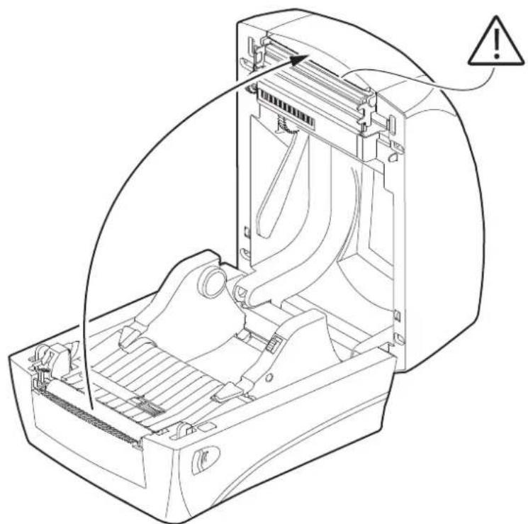
Technical line drawing of an open computer case with a hand operating the internal compartment, showing no text or symbols.Top cover opening see paragraph 5.1.
2
natural_image
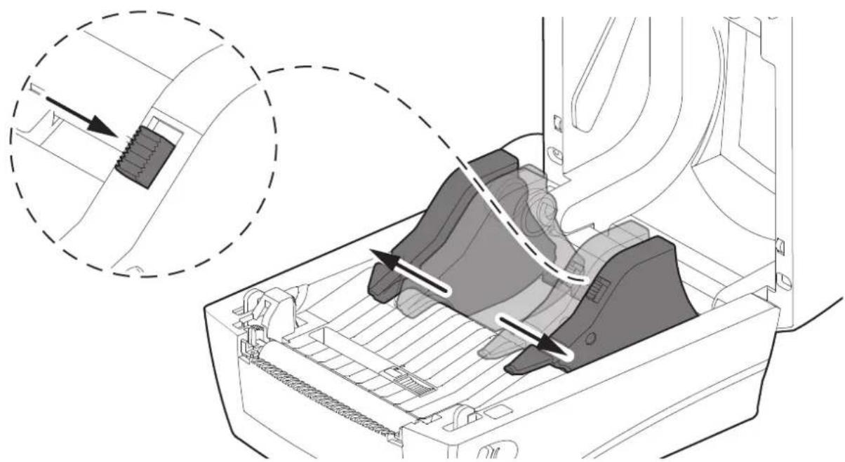
Diagram of a printer's internal structure showing a slot, tray, and printer casing with arrows indicating assembly or component (no text or symbols present)Press and hold the latch and pull the holders open. Release the latch.
3

Insert the label roll. the label roll can be loaded with label inside or outside wound in the same way
4
natural_image
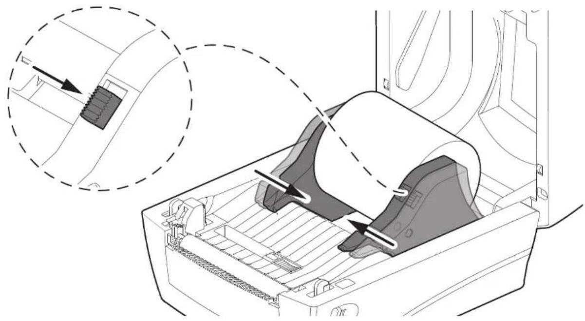
Diagram of a computer monitor with an open case and a magnified inset showing the internal structure (no text or symbols)Press and hold the latch down and adjust the holders until the label roll is firmly supported. Release the latch.
5
natural_image
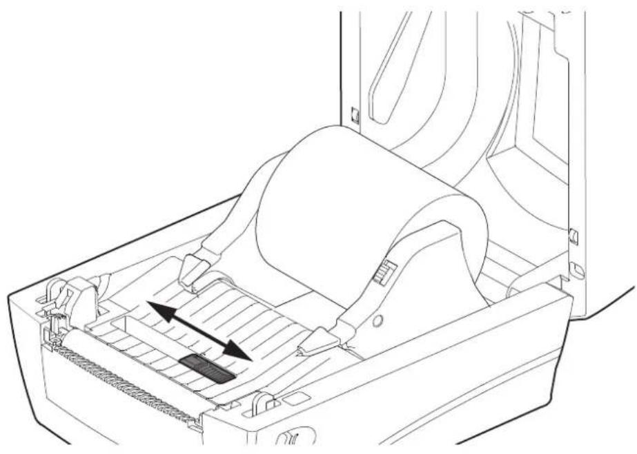
Line drawing of a mechanical device with internal components and directional arrows indicating movement (no text or symbols)Before pushing the labels ribbon under the guides, adjust the label sensor to appropriate position to detect the labels with gap, notch or black mark.
6
natural_image
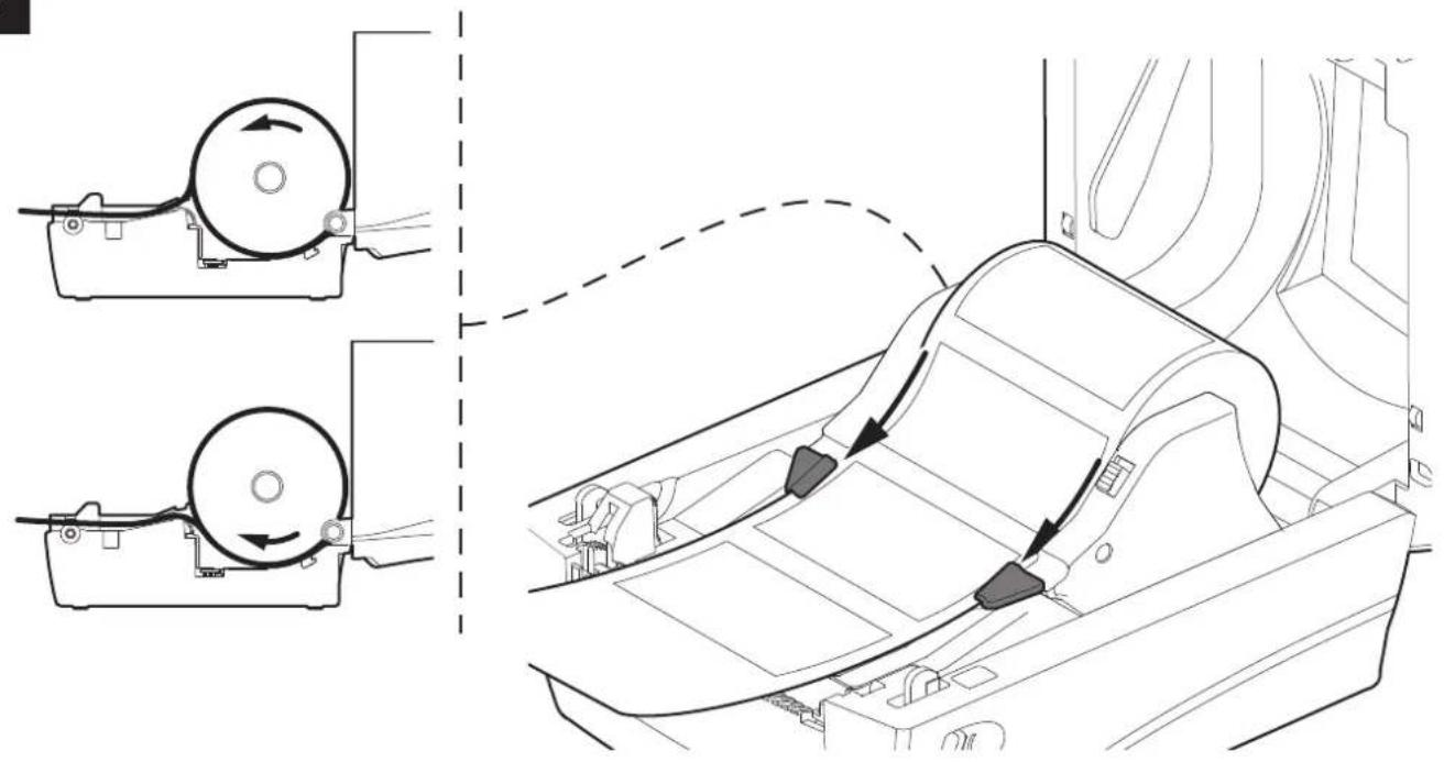
Technical line drawing showing two mechanical components with directional arrows, connected to a car interior (no text or symbols)Pull the label ribbon and pushit under the both guides. Please make sure the printing surface is facing up.
6 MAINTENANCE
6.1 Planning of cleaning operations
The regular cleaning of the device keeps the print quality and extends its life. The following table shows the recommended planning for the cleaning operations. If you use the device in dusty environments, you must reduce the intervals between the cleaning operations.
For specific procedures, see the following pages.
| EVERY PAPER CHANGE |
| Printing head Use isopropyl alcohol |
| Platen roller Use isopropyl alcohol |
| EVERY 5 PAPER CHANGES |
| Manual cutter Use compressed air |
| Paper path Use compressed air or tweezers |
| Sensors Use compressed air |
| EVERY 6 MONTHS OR AS NEEDED |
| Case Use compressed air or a soft cloth |
6.2 Cleaning
For periodic cleaning of the device, see the instructions below.
Platen roller Paper path
1
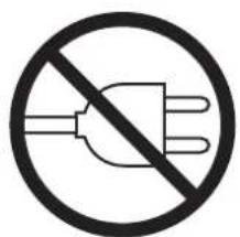
Disconnect the power supply cable and open the ribbon compartment cover (see paragraph 5.1).
2
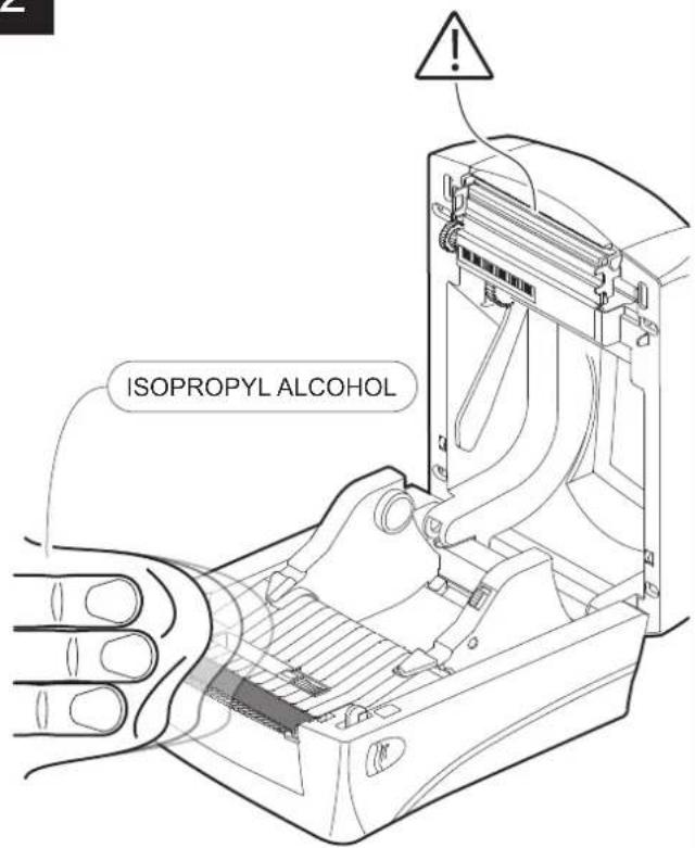
ATTENTION:
Do not use solvents, or hard brushes.
Do not let water or other liquids get inside the device.


Clean the by using a non-abrasive cloth moistened with isopropyl.
1

Disconnect the power supply cable and open the ribbon compartment cover and top cover (see paragraph 5.1).
2
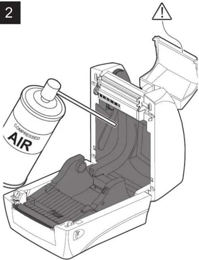
ATTENTION:
Do not use alcohol, solvents, or hard brushes.
Do not let water or other liquids get inside the device.


Remove any scraps of paper and the accumulated paper dust in the inspection compartment and in the paper input area.
Sensor Printing head
1
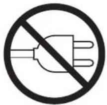
Disconnect the power supply cable and open the ribbon compartment cover (see paragraph 5.1).
2
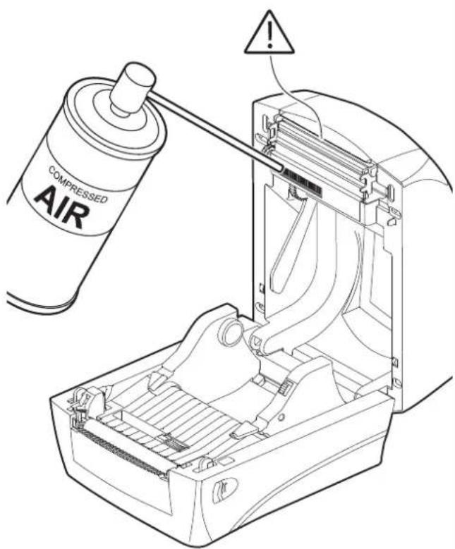
ATTENTION:
Do not use alcohol, solvents, or hard brushes.
Do not let water or other liquids get inside the device.


Clean the paper presence sensor and the sensor for the opening of the inspection door by using compressed air.
1
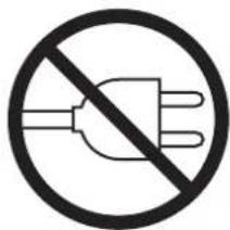
Disconnect the power supply cable and open the ribbon compartment cover (see paragraph 5.1).
2
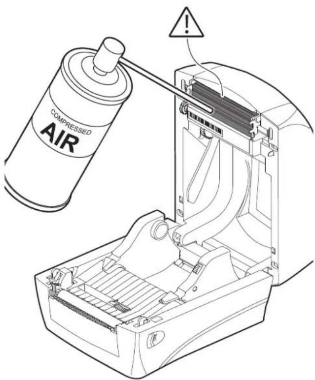
ATTENTION:
Do not use solvents, or hard brushes.
Do not let water or other liquids get inside the machine.
To remove paper scraps, use tweezers or compressed air.


Clean the printing head by using a non-abrasive cloth moistened with isopropyl.
Manual cutter Chassis
1
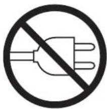
Disconnect the power supply cable and open the ribbon compartment cover (see paragraph 5.1).
2
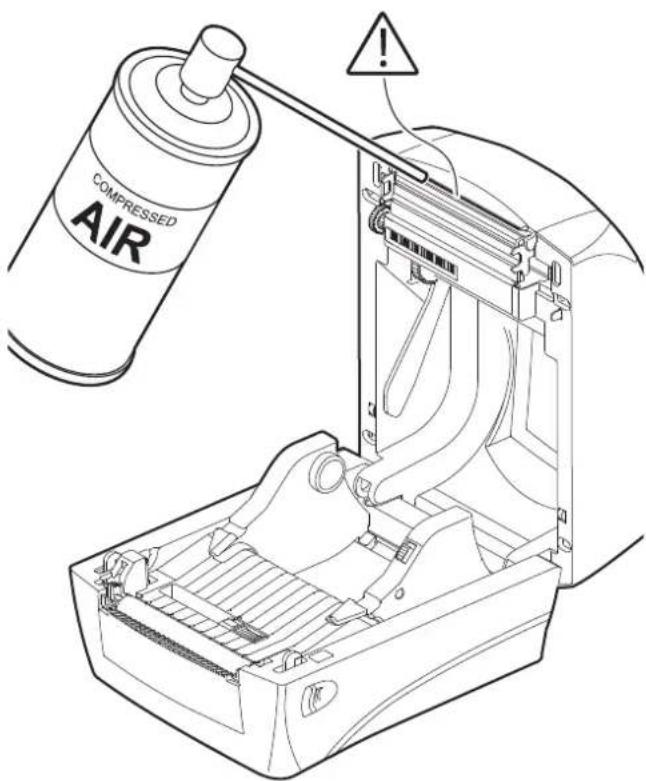
ATTENTION:
Do not use alcohol, solvents, or hard brushes.
Do not let water or other liquids get inside the machine.
To remove paper scraps, use tweezers or compressed air.


Clean the autocutter by using compressed air.
1
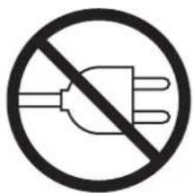
Disconnect the power supply cable.
2
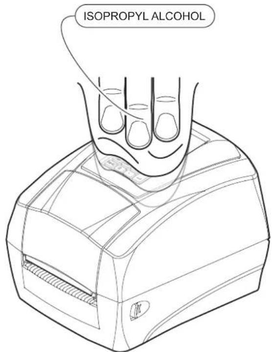
ATTENTION:
Do not use alcohol, solvents, or hard brushes.
Do not let water or other liquids get inside the device.


To clean the device, use compressed air or a soft cloth.
It's possible to operate the device alone without connecting PC to print labels.
This section shows the way how to operate the standalone operation.
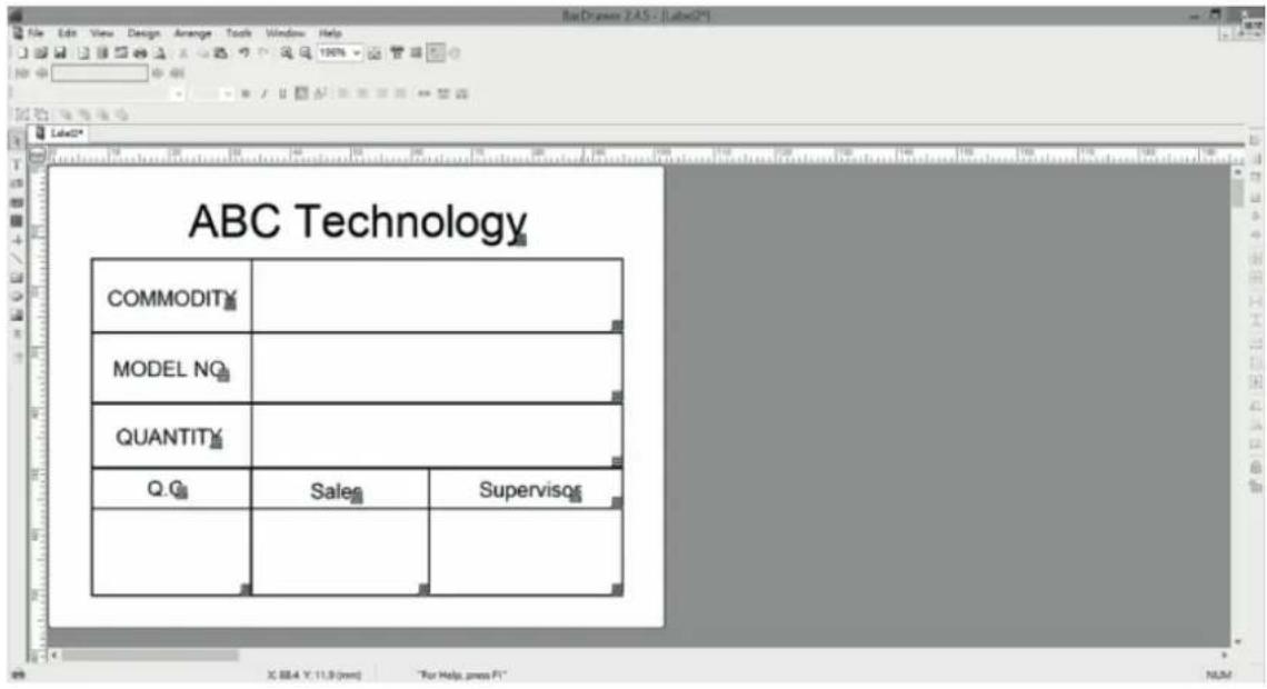
- Create a new blank label.
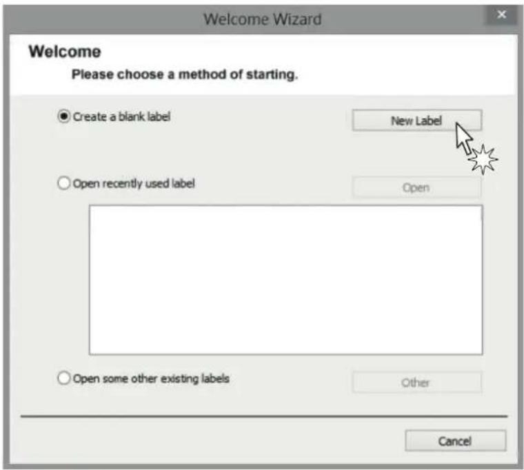
- Select "Make form" and press Finish key.
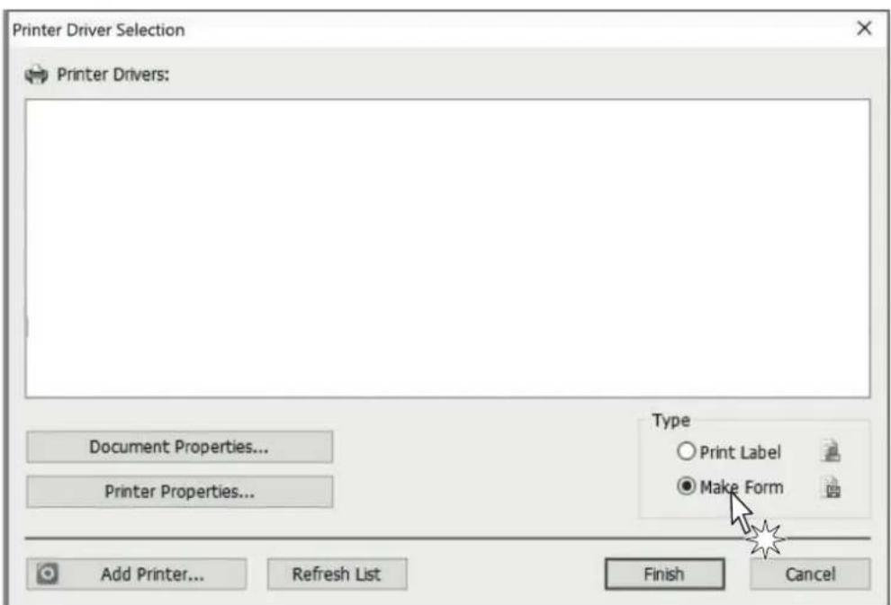
- Edit your label.
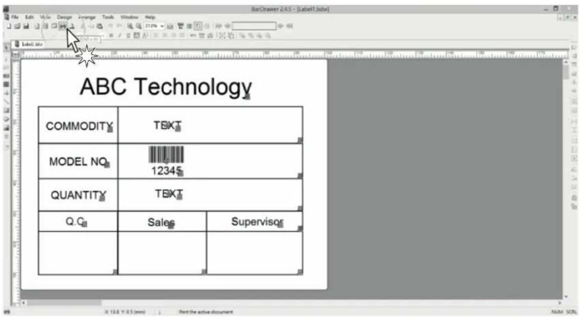
- Press "Print" icon key.
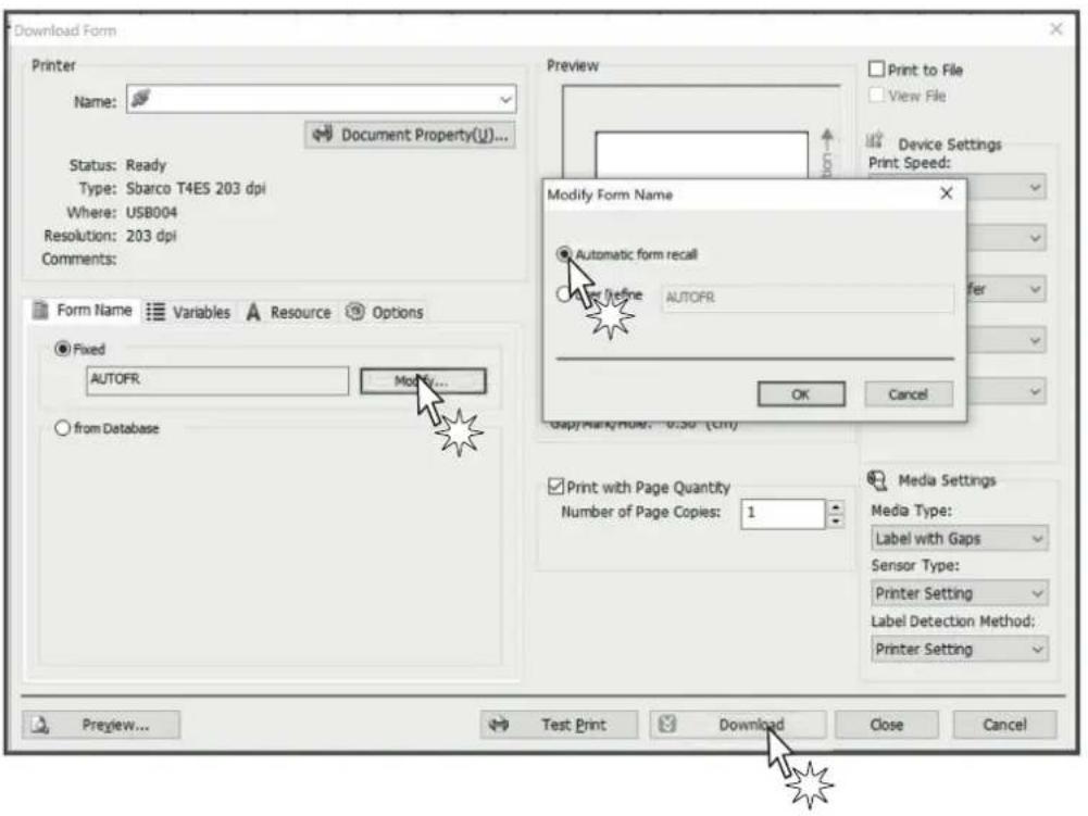
- Press "Modify" key / select "Automatic form recall" / press "Download".
- Save the form into Printer's Flash ROM.
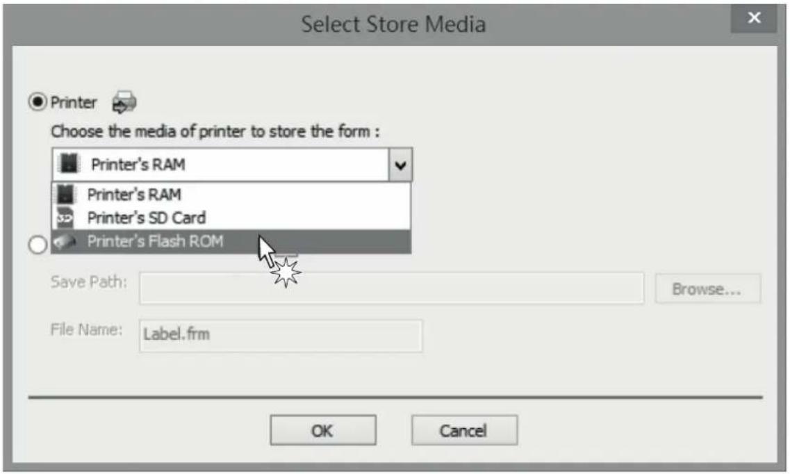
After downloaded the form into the printer's flash ROM, the 3D indicator will be turned to purple color.
- To cancel the Standalone power off the device. Keep press the FEED key then power on the device, note to wait that the 3D indicator light start flashing and turn to purple again and release the Feed key. Open your computer device tool / file manager / delete the form from the form list.
8 STANDALONE OPERATION D4 202 AND D4 302-K
It's possible to operate the device alone without connecting PC to print label by using normal USB interface keyboard or scanner.
8.1 Description of keyboard
![esc F1 F2 F3 F4 F5 F6 F7 F8 F9 F10 F11 F12 ▲ delete - ! @ # $ % ^ & * ( ) - + home , 1 2 3 4 5 6 7 8 9 0 = back space tab Q W E R T Y U I O P [ ] | pg up caps lock A S D F G H J K L : " enter pg dn shift Z X C V B N M < > ? shift end fn control alt option command command option ▲ BD](/content/2026/05/935136/images/6a150923154f9d5f064014559e5ff61968528c62e8d14074dd5f2cbf58d931ce.jpg)
Where:
| PRINTER STATUS MAIN MENU SUB MENU KEY FUNCTION DESCRIPTION | |
| Ready | F1 Enter / Exit LCD Menu |
| F4 Feed | |
| Printing | F2 Cancel printing job |
| F3 Pause printing job | |
PRINTER STATUS MAIN MENU SUB MENU KEY FUNCTION DESCRIPTION
| ~!@#$%^&*()-+`0~9_= | ||
| {}|:"<>?[]\;,./ | ||
| A~Z | Data | |
| a~z | ||
| 0~9 | ||
| Space | ||
| Form operation Form Run the form Auto form | ESC | |
| Caps Lock | ||
| Left Shift | ||
| Right Shift | ||
| Backspace | ||
| Home | Control key | |
| Delete | ||
| End | ||
| ← | ||
| → | ||
| Num lock | ||
PRINTER STATUS MAIN MENU SUB MENU KEY FUNCTION DESCRIPTION
| LCD menu | Menu Item | ↑ Scroll up | ||
| ↓ Scroll down | ||||
| ESC | Return to last menu level | |||
| Enter Enter menu item | ||||
| Setting | ↑ Scroll up | |||
| ↓ Scroll down | ||||
| ESC Return | ||||
| Enter Save | ||||
| User setup | Date ↑ Scroll up | |||
| Time ↓ Scroll down | ||||
| Password ESC Return | ||||
| Enter | Save / Next setting item | |||
| Print setup | Darkness | ↑ Add value | ||
| Print width | ||||
| Print x offs | ↓ Reduce value | |||
| Print yoffs | ||||
| Tph y offs | ESC Return | |||
| Back y offs | ||||
| Enter Save | ||||
| Test | Print config | ↑ | Add Item | |
| Print test | ||||
| Label cal. | ||||
| Dump mode | ↓ | Next item | ||
| Cutter | ||||
| Memory | Free size | |||
| List | ESC Return | |||
| Delete files | ||||
| Clear memory | ||||
| Form | Run the form | Enter | Select / Run function | |
| Auto form | ||||
| F/W update | ||||
- Create a new blank label.
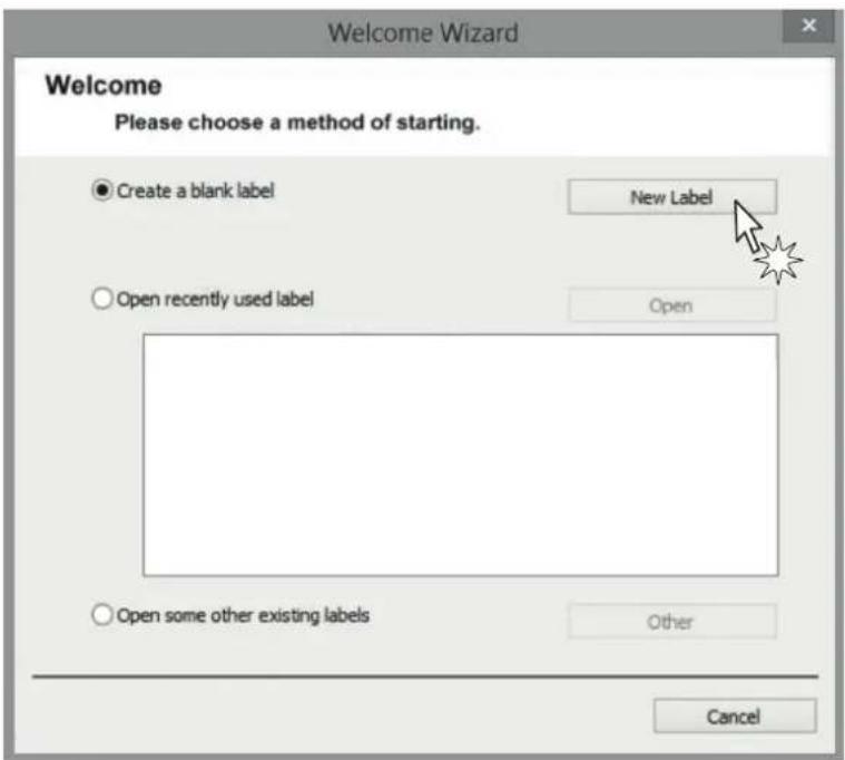
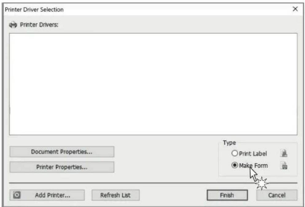
- Select
- "Print Label" to crate a label or
- "Make Form" to crate a template with variable fields
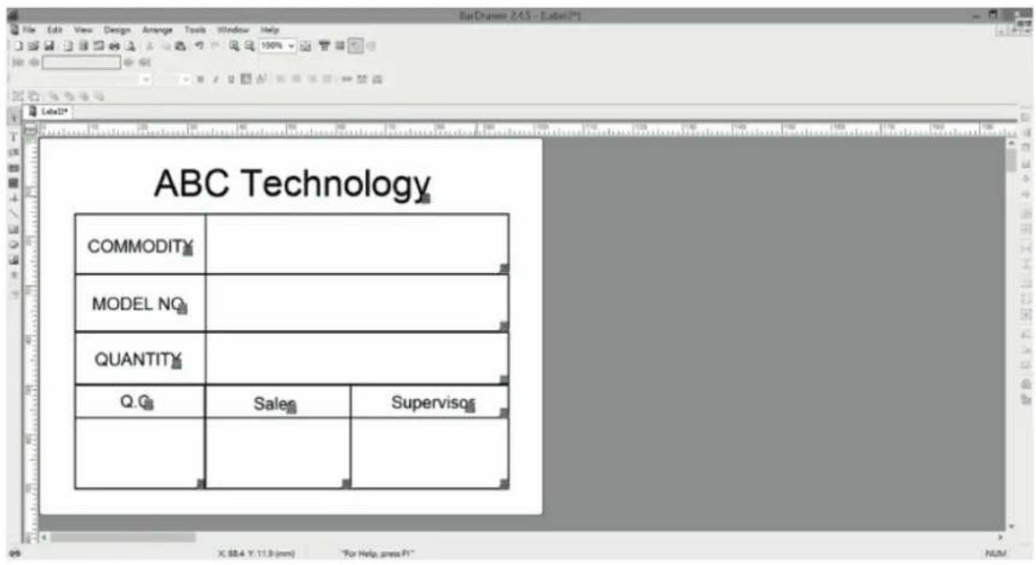
- Edit a form.
- Enter the "Text" or Barcode in editing field.
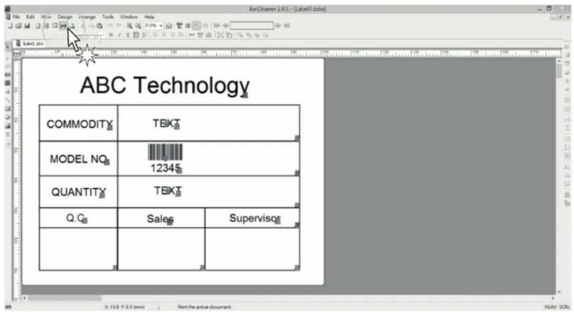
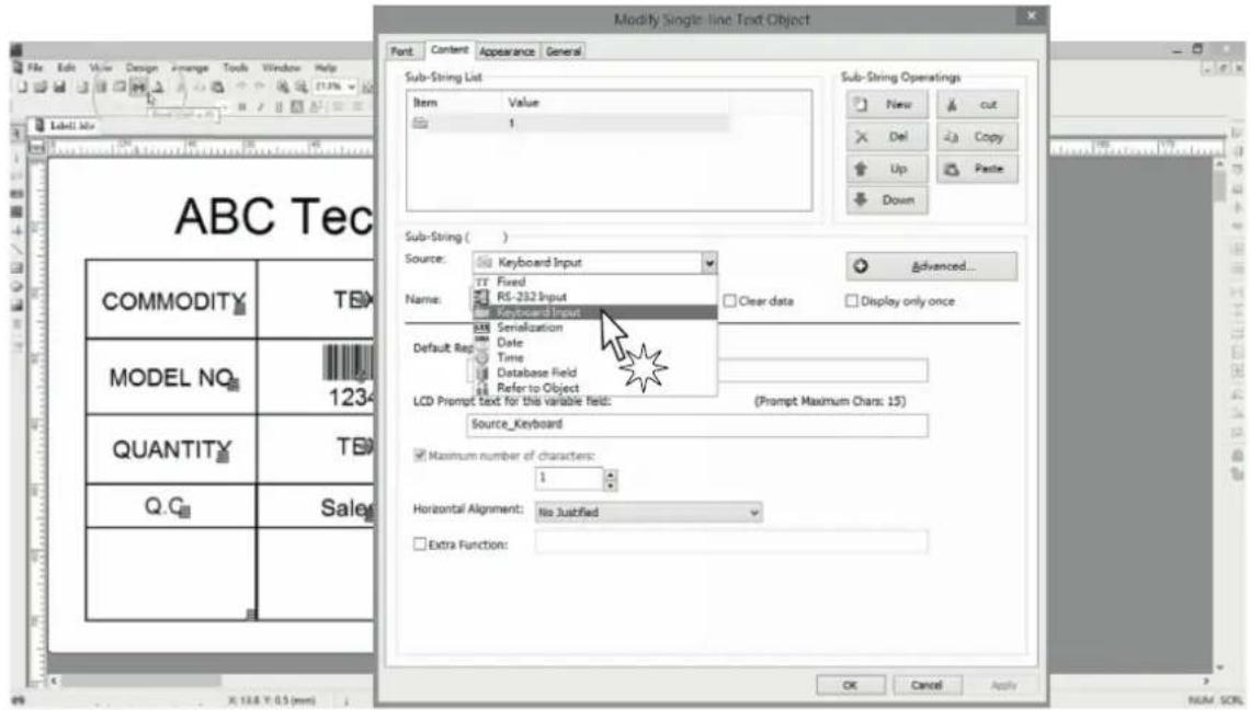
- Click twice on the "Text", select "Keyboard input" in Source field.
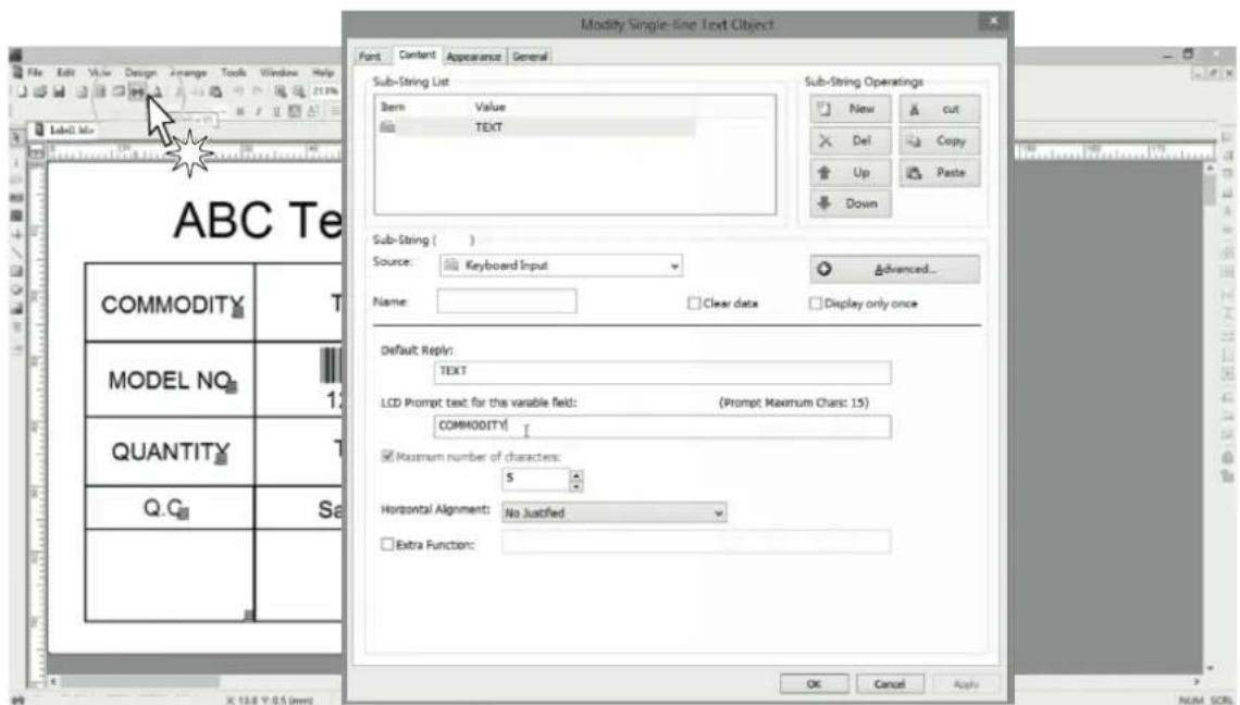
- Enter the prompt text would like to be shown on LCD monitor. Enter also the max characters.
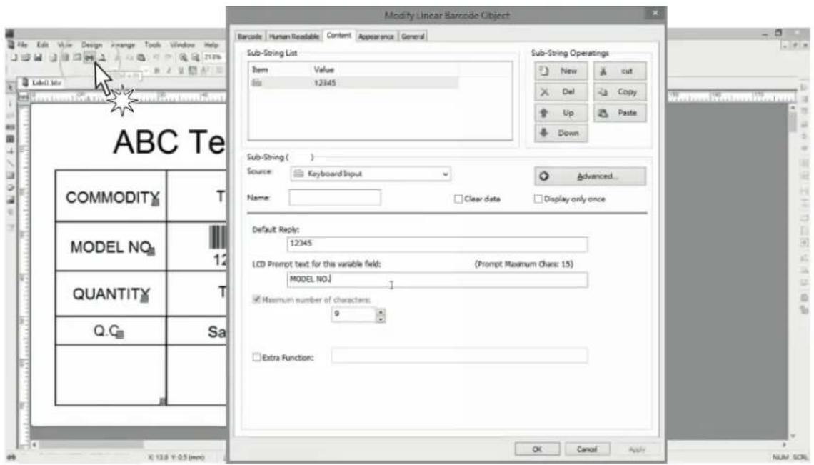
- Follow the last step for the other variable text.
- Press "Print" key.

- Press "Modify" key to modify the form name.
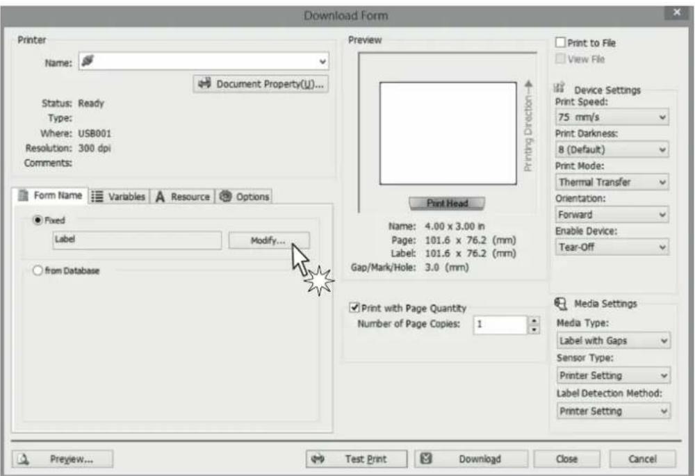
- Modify the form name.
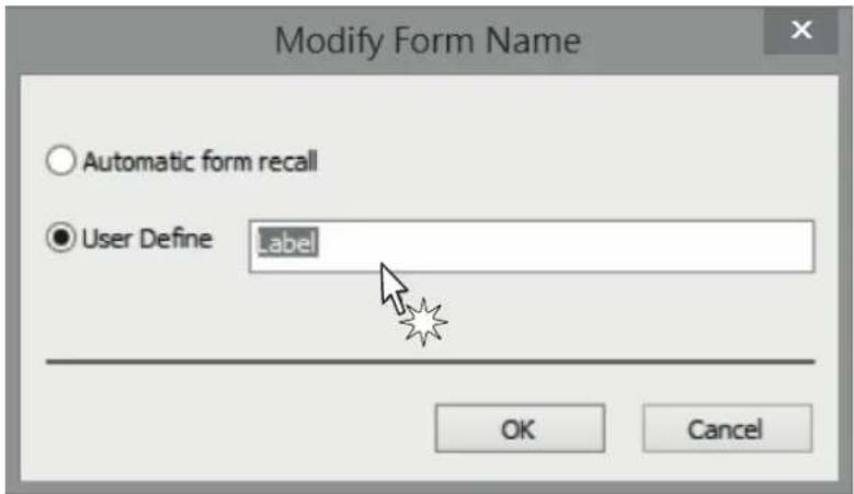
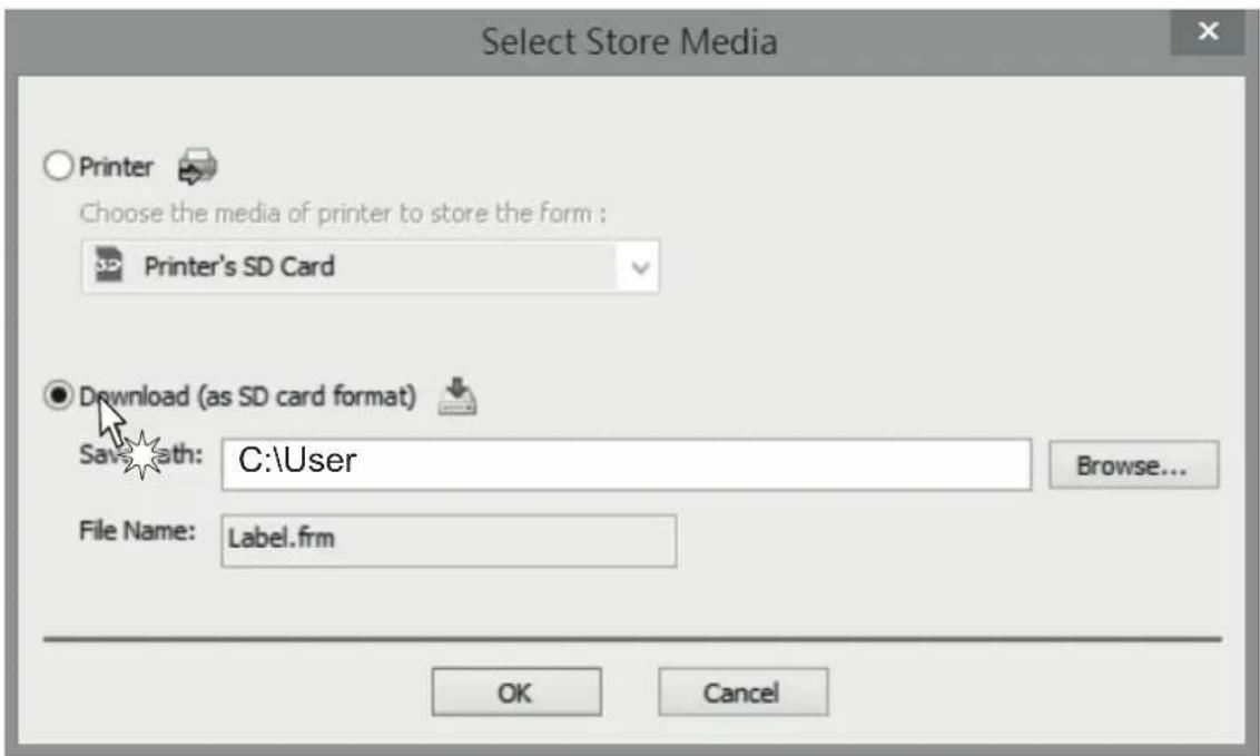
After modifying the form name, press "Download" and "Save" to load the form to memory device.
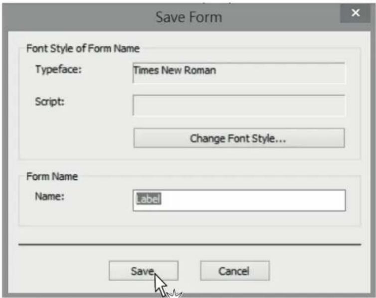
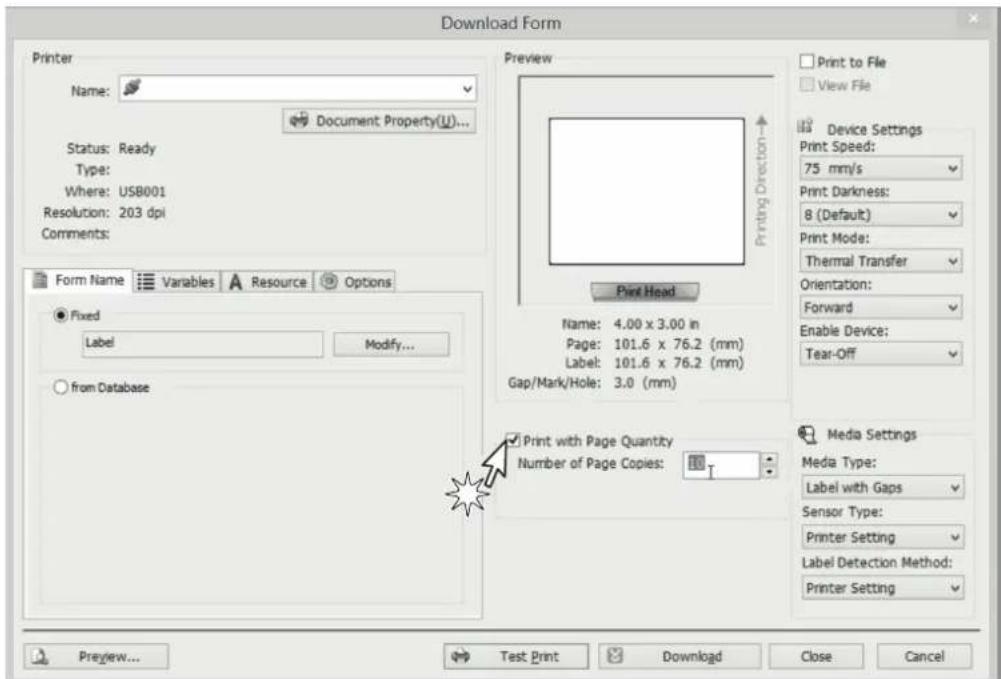
- There 3 ways you could store the form into Printer's: RAM, Flash ROM or SD card.
- After downloaded the form into the printer's flash ROM, check the FORM LIST in memory of printer menu. The form name "Label" will be shown in FORM list.
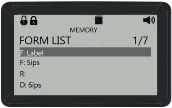
Where:
R: Form is stored in device's SDRAM. The Form will disappear when device's power is off
F: Form is stored in device's Flash ROM. The Form is saved in memory even power off the device
D: Form is stored in SD card.
- Select the form Shipping label in the menu of "RUN THE FORM"
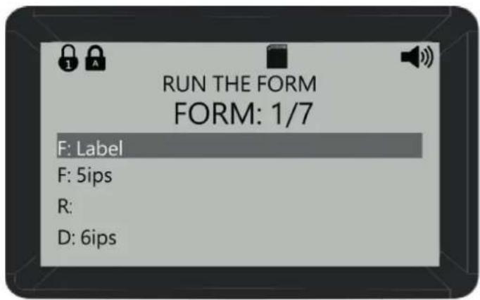
- Follow the prompt text you set to enter the data from the keyboard:
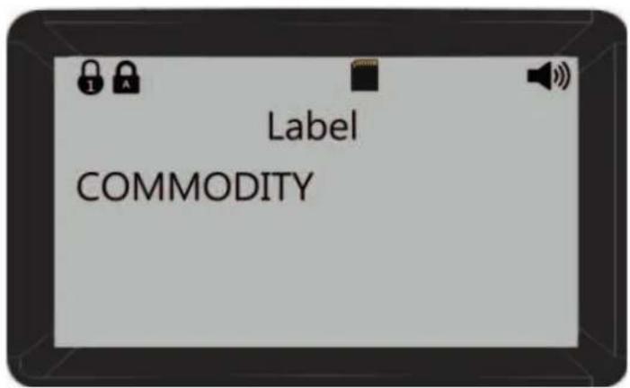
-
Enter the commodity
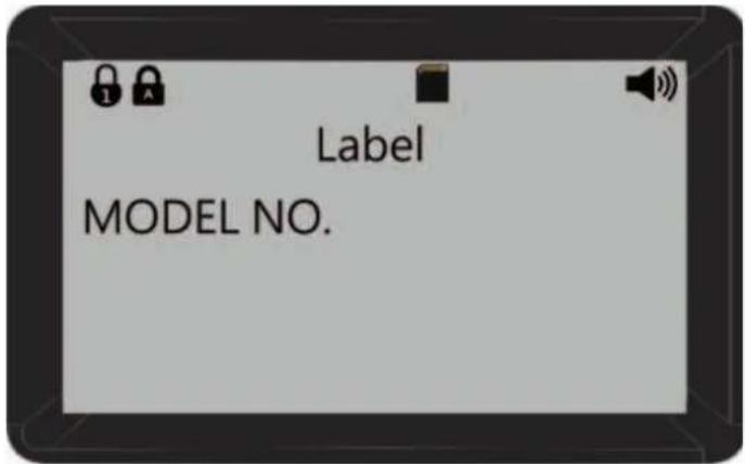
-
Enter the model No
- Enter the quantity
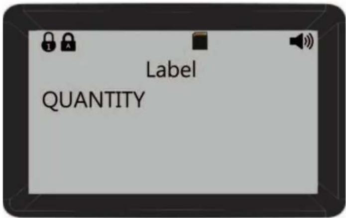
- Then, the printer will device the label quantity you set, if you set already the device quantity.
8.2 Instruction guide of SD card
After saved files into SD card, all of these files can be managed through PC. You can check description and detailed steps in the following parts:
- After complied file, insert SD card into device.
- The function of saving editing record can be activated by "records setup".
![BarDrawer 2.4.5 - [Label1*] File Edit View Design Arrange Tools Window Help Arial 12 B I U A 404% Label1* shipping](/content/2026/05/935136/images/46e74bb6bc2c4a3a32e115836459b854575ba74004cac0c8af3b6a3d2b0a8b2f.jpg)
- Click the "records setup", then check "enable the storage function". Choose the items which are needed to be recorded, and then click ">>". Besides, "<<" can be used to delete item.
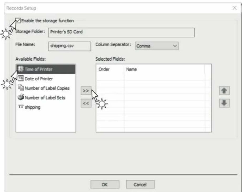
- You can add or remove items according to your need. Click "OK" after you completed selection.
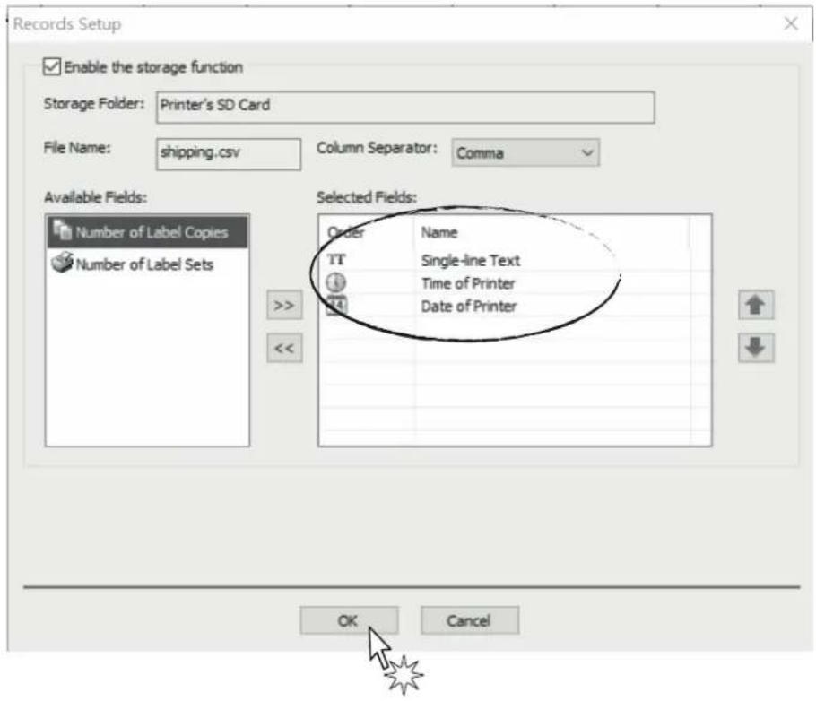
- Remove SD card from printer and insert it into PC, the description of folders is showed below:
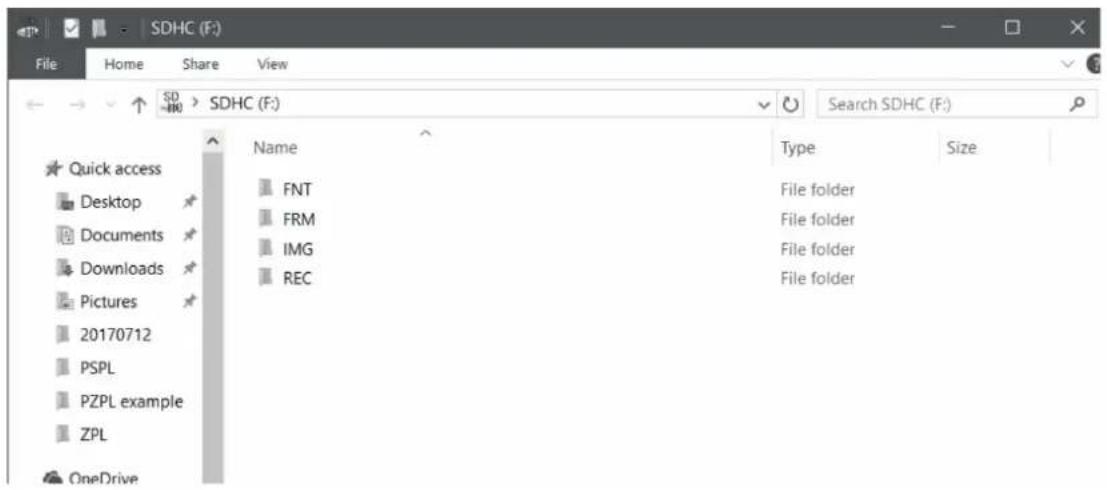
Where:
| FOLDER CATEGORY OF FILE EXTENSION |
| FRM form .frs |
| REC record .csv |
| IMG image .ims |
| FNT font .fns |
8.3 Check out printing records
If you need to check out printing records, open the folder "REC" and then find out the file which is named the same as form.
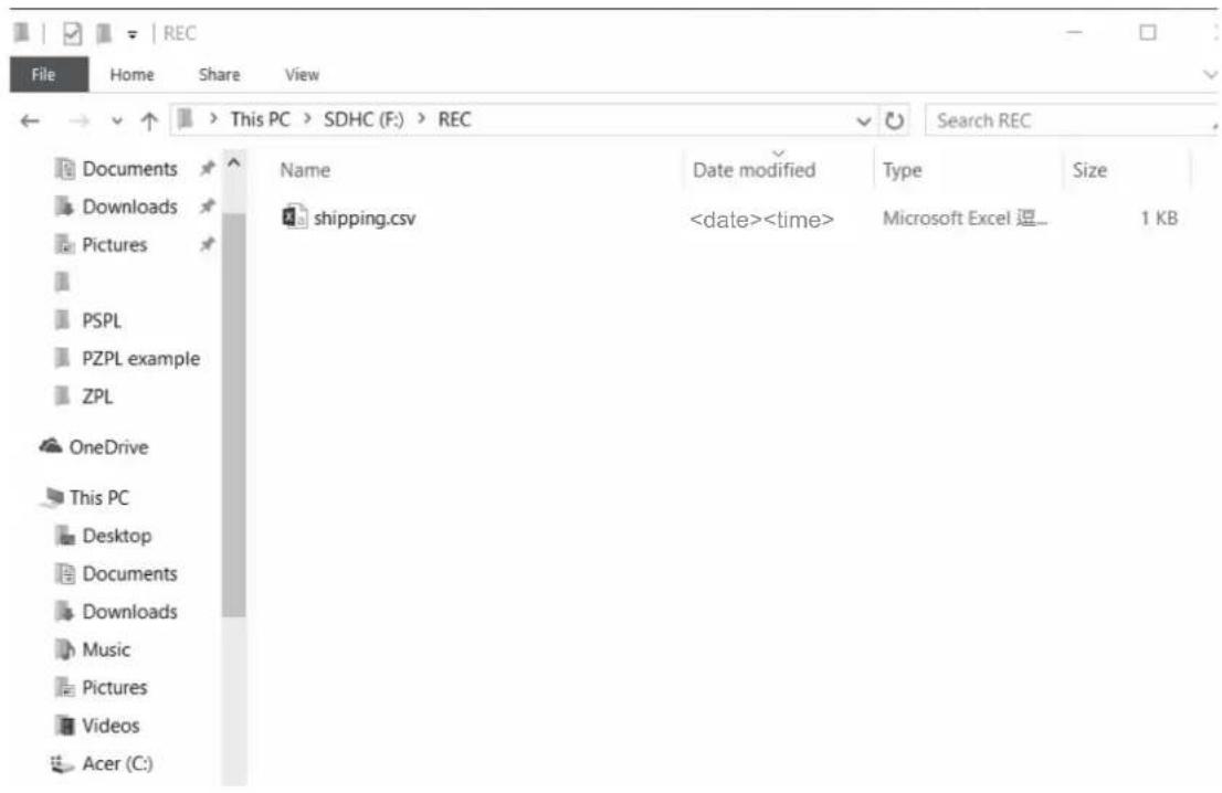
• After opened the file, all of the printing records will show up via Excel file format.
| K6 | |||||||
| A | B | C | D | E | F | ||
| 1 | shipping | ||||||
| 2 | shipping | ||||||
| 3 | shipping | ||||||
| 4 | |||||||
| 5 | |||||||
| 6 | |||||||
| 7 | |||||||
| 8 | |||||||
| 9 | |||||||
| 10 | |||||||
| 11 | |||||||
8.4 Download firmware
This part is the instruction of how to download firmware through SD card. There are steps in the following:
- Save firmware file into SD card. Note that the file must be named "FwRLS.fwt".
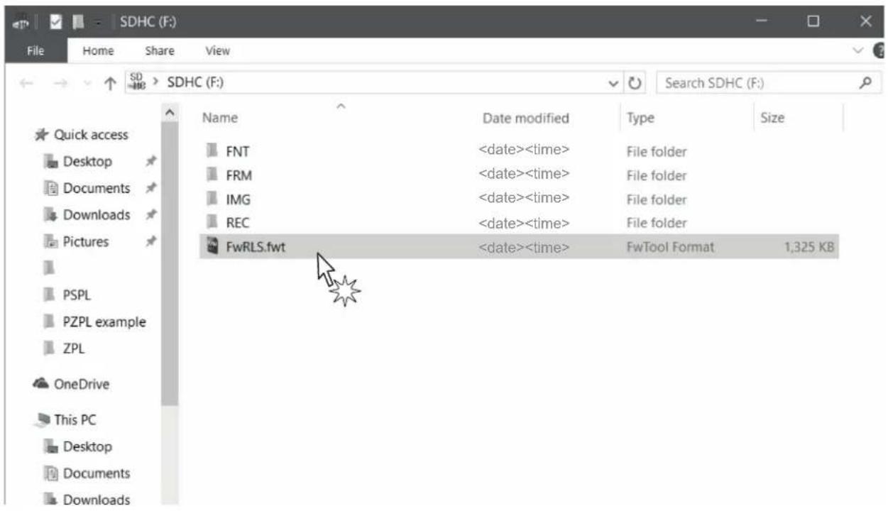
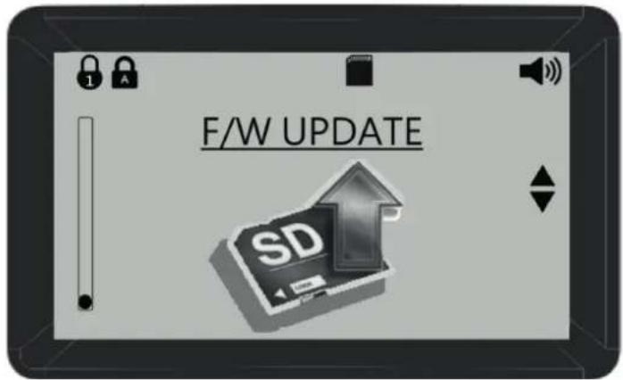
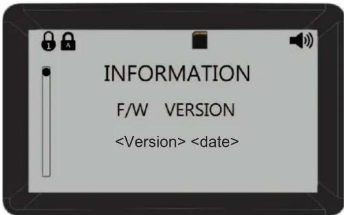
- Press "MENU", and then choose "F/W update".
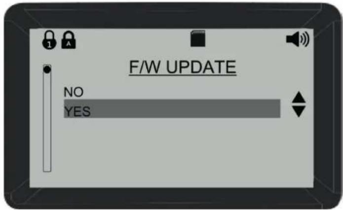
- Press "YES", and then the printer will update to the firmware version which has been chosen.
- You can check out the firmware version in "INFORMATION".
8.5 Files converter (from frm. to frs.)
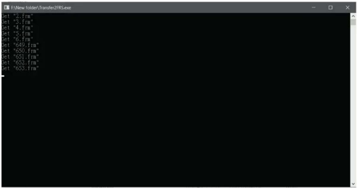
- Put the files you want to convert into a new folder, and then copy the converter named Transfer2FRS.exe from the CD to the folder.
| Name | Date modified | Type | Size |
| ✓ Application (1) | |||
| Transfer2FRS.exe | Application | 2,933 KB | |
| ✓ Pro/E Format File (30) | |||
| 2.frm | Pro/E Format File | 87 KB | |
| 3.frm | Pro/E Format File | 87 KB | |
| 4.frm | Pro/E Format File | 87 KB | |
| 5.frm | Pro/E Format File | 87 KB | |
| 6.frm | Pro/E Format File | 87 KB | |
| 649.frm | Pro/E Format File | 88 KB | |
| 650.frm | Pro/E Format File | 88 KB | |
| 651.frm | Pro/E Format File | 88 KB | |
| 3 Drive (F:) > Application > | |||
| Name | Date modified | Type | Size |
| Fonts | File folder | ||
| PrnDrv-1.6.5-140626 | File folder | ||
| BarDrawer-2.4.6-20180315.msi | Windows Installer ... | 17,249 KB | |
| BarDrawerManual 2.3.2 - | PDF File | 6,575 KB | |
| InstallManual-1.2.pdf | PDF File | 7,902 KB | |
| Transfer2FRS.exe | Application | 2,933 KB | |
| Name | Date modified | Type | Size |
| Application (1) | |||
| Transfer2FRS.exe | Application | 2,933 KB | |
| FRS File (12) | |||
| 2.frs | FRS File | 87 KB | |
| 3.frs | FRS File | 87 KB | |
| 4.frs | FRS File | 87 KB | |
| 5.frs | FRS File | 87 KB | |
| 6.frs | FRS File | 87 KB | |
| 649.frs | FRS File | 88 KB | |
| 650.frs | FRS File | 88 KB | |
| 651.frs | FRS File | 88 KB | |
| 652.frs | FRS File | 88 KB | |
| 653.frs | FRS File | 88 KB | |
| 654.frs | FRS File | 88 KB | |
| 655.frs | FRS File | 88 KB | |
| Pro/E Format File (10) | |||
| 2.frm | Pro/E Format File | 87 KB | |
| 3.frm | Pro/E Format File | 87 KB | |
| 4.frm | Pro/E Format File | 87 KB | |
| 5.frm | Pro/E Format File | 87 KB | |
| 6.frm | Pro/E Format File | 87 KB | |
< Move to SD card >
Insert an empty SD card into the printer, and it will be added 4 folders automatically. Copy the converted files to the folder named FRM.
1. < SD card >
| USB Drive (E:) > | ||||
| Name | ^ | Date modified | Type | Size |
| FNT | <date><time> | File folder | ||
| FRM | <date><time> | File folder | ||
| IMG | Type: File folder Date modified: <date><time> Empty folder | |||
| REC | ||||
2.
| Name | Date modified | Type | Size |
| 2.frs | FRS File | 87 KB | |
| 3.frs | FRS File | 87 KB | |
| 4.frs | FRS File | 87 KB | |
| 5.frs | FRS File | 87 KB | |
| 6.frs | FRS File | 87 KB | |
| 649.frs | FRS File | 88 KB | |
| 650.frs | FRS File | 88 KB | |
| 651.frs | FRS File | 88 KB | |
| 652.frs | FRS File | 88 KB | |
| 653.frs | FRS File | 88 KB | |
| 654.frs | FRS File | 88 KB | |
| 655.frs | FRS File | 88 KB |
9 SPECIFICATIONS
9.1 Hardware specifications
| GENERAL | |
| Model | D4 102D4 202D4 302-K |
| CPU 32-bit CPU | |
| Sensors | Hole and black mark movable sensorRibbon sensorRibbon compartment cover sensor |
| Printing driver | Windows XPVISTA (32/64 bit)Windows 7 (32/64 bit)Windows 8 (32/64 bit)Windows 8.1 (32/64 bit)Windows 10 (32/64 bit) |
| Audio Beep sound when error occurs | |
| INTERFACES | |
| D4 102 | USB slave portEthernet port 10 Mbit/s, 100 Mbit/s,(optional) |
| D4 202D4 302-K | USB A portUSB B portRS232 serial port from 9600 bps to 115200 bpsEthernet port 10 Mbit/s, 100 Mbit/s,(optional) |
| MEMORY | |
| D4 102 | RAM: 64MB SDRAMROM: 128MB Flash ROM |
| D4 202D4 302-K | RAM: 128MB DDRAMROM: 128MB Flash ROMExpendable slot for SD card (up to 32GB) |
CONTROL PANEL
| D4 102 | 1 multi-functional key |
| 1 LED light (Red, blue, purple) |
D4 202 4 multi-functional keys
D4 302-K 19 multi-functional keys
DISPLAY
D4 202
D4 302-K
Colorful LCD display 320x240 dots
PAPER
| Ribbon label | max. label width: 110 mmmin. label width: 15 mmmax. roll diameter: 127 mmcore diameter: 25.4 mmRibbon label thickness: from 0.06 mm to 0.2 mmRibbon label thickness type: Continuous, die-cut, tag, fan-fold, black mark |
| Ribbon | OD: 39 mmmax length: 100 mwidth: from 25.4 mm to 110 mmID: 12.7 mmtype: Wax, wax/resin, resin |
PRINTER
Resolution 203/300 dpi
| Print mode | Direct Thermal Thermal Transfer |
Print length Max. 3810 mm
Print width 104 mm
| Print speed | 203 dpi 1 to 5 ips (option up to 6 ips) |
| 300 dpi 1 to 4 ips |
| 1D barcodes | Code39 standard or extended, Code39 with check digit, Code93, Code128 UCC, Code128 auto A,B,C modes, Codabar, EAN8, EAN8/13 2&5 digit add-on, EAN13, Interleaved 2 of 5, Interleaved 2 of 5 with check digit, Interleaved 2 of 5 with human readable check digit, UCC/EAN 128, UPC A, UPC A 2&5 digit add-on, UPC E, UPC E 2&5 digit add-on, UPC Interleaved 2 of 5, Code11 |
2D barcodes Data Matrix, MaxiCode, PDF417, QR code
| Fonts | 5 internal expandable bitmap fonts (alpha-numeric)2 internal expandable bitmap fonts (numeric only)Downloadable soft font4 directions: 0, 90, 180, 270 degrees |
| Image | PEPL: PCX, Direct binary graphicPDPL: PCX, BMP, HEXPZPL: HEX, Direct binary graphic, Compressed binary |
| Dimension | Width: 200.00 mmLength: 263.19 mmHeight: 188.29 mmWeight: 2000 g |
| AUTOCUTTER | |
| Paper cut Total cut | |
| ELECTRICAL SPECIFICATIONS POWER SUPPLY cod. 48000000018500 | |
| Power supply voltage from 100 Vac to 240 Vac | |
| Frequency from 50 Hz to 60 Hz | |
| Output 24 V, 2.5 A | |
| Power 60 W | |
| ENVIRONMENTAL CONDITIONS | |
| Operating temperature from -10°C to +60°C | |
| Relative humidity (RH) from 10% to 85% (w/o condensation) | |
| Storage temperature from -20 °C to +70 °C | |
| Storage relative humidity (RH) from 10% to 90% (w/o condensation) | |
10 ACCESSORIES
The following table shows the list of the available accessories for the devices.
D4 102, D4 202, D4 302-K
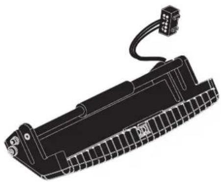
976MK010000002
PEELER MODULE
natural_image
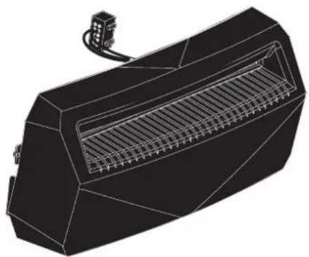
Technical line drawing of a battery pack with a cable and terminal connector (no text or symbols)976MK010000001
CUTTER MODULE
natural_image
3D technical illustration of a portable air conditioner unit with internal grid structure (no text or symbols)D4 202, D4 302-K
979MK020000001
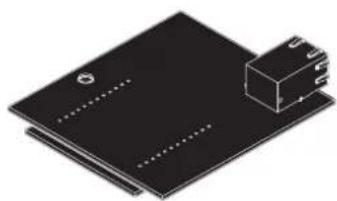
ETH MODULE
natural_image
Illustration of a black electronic component with a small rectangular block on top (no text or symbols)11 TECHNICAL SERVICE
In case of failure, contact the technical service accessing the website www.custom4u.it and using the support tools on the homepage. It is advisable to keep the identification data of the product at hand.
CUSTOM®
CUSTOM S.p.A.
World Headquarters
Via Berettine, 2/B - 43010 Fontevivo, Parma ITALY
Tel. +39 0521 680111 - Fax +39 0521 610701
- Customer Service Department: www.custom4u.it
- THE IMAGES USED IN THIS MANUAL ARE USED AS AN ILLUSTRATIVE EXAMPLES. THEY COULDN'T REPRODUCE THE DESCRIBED MODEL FAITHFULLY.
- UNLESS OTHERWISE SPECIFIED, THE INFORMATION GIVEN IN THIS MANUAL
- ARE REFERRED TO ALL MODELS IN PRODUCTION AT THE ISSUE DATE OF THIS DOCUMENT.
- GENERAL INSTRUCTIONS
- GENERAL SAFETY INFORMATION
- THE CE MARK AFFIXED TO THE PRODUCT CERTIFY THAT THE PRODUCT SATISFIES THE BASIC SAFETY REQUIREMENTS.
- GUIDELINES FOR THE DISPOSAL OF THE PRODUCT
- TABLE OF CONTENTS
- INTRODUCTION
- IDENTIFICATION OF THE MODELS
- DESCRIPTION
- Box contents
- D4 102
- D4 202
- D4 302-K
- Device components: external views
- Connectors panel
- D4 202, D4 302-K
- Device components: internal view
- D4 102, D4 202, D4 302-K
- Product label
- Control panel
- GRAPHIC SYMBOL FUNCTION DESCRIPTION
- LCD screen icons
- USER SETUP
- COMM. SETUP
- PRINT SETUP
- TEST
- INSTALLATION
- Connections
- Pinout
- USB INTERFACE
- ETHERNET INTERFACE (Optional)
- NOTES:
- USB INTERFACE (D4 202/
- RS232 SERIAL INTERFACE
- Driver and SDK
- OPERATION
- Opening the top cover
- Opening the ribbon compartment cover
- Opening the frontal cover
- Switch the device on
- Loading the ribbon roll
- Loading the ribbon label roll
- MAINTENANCE
- Planning of cleaning operations
- Cleaning
- Platen roller Paper path
- 1
- 2
- Sensor Printing head
- Manual cutter Chassis
- STANDALONE OPERATION D4 202 AND D4 302-K
- Description of keyboard
- Where:
- Instruction guide of SD card
- Check out printing records
- Download firmware
- Files converter (from frm. to frs.)
- < SD card >
- 2.
- SPECIFICATIONS
- Hardware specifications
- ACCESSORIES
- TECHNICAL SERVICE
- CUSTOM®
Brand : CUSTOM
Model : D4 102
Category : Label printer