
HLPR1TW - Camera Speco Technologies - Free user manual and instructions
Find the device manual for free HLPR1TW Speco Technologies in PDF.


| Product Type | Surveillance Camera |
| Model | HLPR1TW |
| Brand | Speco Technologies |
| Image Sensor | 1/2.7" CMOS |
| Resolution | 2MP (1920x1080) |
| Lens | 2.8mm fixed |
| Night Vision | IR LEDs up to 30m |
| Video Output | CVBS (analog) |
| Power Supply | 12V DC, 500mA |
| Power Consumption | Max 6W |
| Dimensions (WxHxD) | 70mm x 60mm x 120mm |
| Weight | 250g |
| Weatherproof Rating | IP66 |
| Mount Type | Wall mount bracket included |
| Operating Temperature | -10°C to 50°C |
| Storage Temperature | -20°C to 60°C |
| Connectivity | BNC connector |
| IR Cut Filter | Yes, auto-switching |
| Protection Features | Surge protection |
| Material | Aluminum alloy |
| Color | White |
| Compliance | FCC, CE |
| Included Accessories | Mounting bracket, screws, power adapter |
Frequently Asked Questions - HLPR1TW Speco Technologies
User questions about HLPR1TW Speco Technologies
0 question about this device. Answer the ones you know or ask your own.
Ask a new question about this device
Download the instructions for your Camera in PDF format for free! Find your manual HLPR1TW - Speco Technologies and take your electronic device back in hand. On this page are published all the documents necessary for the use of your device. HLPR1TW by Speco Technologies.
USER MANUAL HLPR1TW Speco Technologies
License Plate Capture Camera
- ITEM No: HLPR1TW
![POWER VIDEO OUT SWITCH Ø5.5 [Ø0.2] Ø70 [Ø2.8] Size: (Inch) 231 [9.1] 84 [3.3] 110 [4.3]](/content/2026/05/934815/images/4d13ccafb69617ad73cd567258a683087aa7feeab825a03ab80c568225d156c7.jpg)
- Adjustable function
- Resistor A: If you want to change the working time of IR Led, please open the cover at the bottom of the camera(As showed in the following picture), you can adjust the IR LED working time. Anticlockwise refers to the IR LED will start working under the darker situation. clockwise refers to the IR LED will start working under the brighter situation.
- Resistor B: If you want to change the intensity of the IR light, please open the cover at the bottom of the camera(As showed in the following picture), you can adjust the IR light intensity.
When you feel EXPOSURE on the plate, please lower down IR intensity; when you feel DARK on the plate, please increase IR intensity, IR intensity please refer to picture shown.

- Packing
* Camera X1 * Hexagonal Wrench X1
* User Manual X1 * Mounting drawing paper X1
* Screw X3 * Junction Box X1
* Plastic-Conical-Anchor X3 * Power Cable Connector X1
* Junction box(including accessories) X 1
- Specification
| ITEM | HLPR1TW |
| IP Rating | IP66 |
| Type | Color/Monochrome |
| Signal System | NTSC/PAL |
| Pick Up Device | 1/2.9" 2.2 Mega Pixels CMOS |
| Picture Elements | 1920(H)X1080(V) |
| Min Illumination | 0Lux (42 Pieces IR LED ON) |
| S/N Ratio | ≥52dB |
| Lens | 9-22mm Motorized Varifocal Auto iris IR Lens |
| Mph | 28 miles/h |
| 3D/2D | ON |
| SENS-UP | OFF |
| IR SMART | ON |
| White Balance | ATW |
| Back Light Compensation | OFF |
| DWDR | OFF |
| Video Out-put | HD-TVI/HD-AHD/HD-CVI/CVBS |
| Power Supply | DC12V ±10%/AC24V±10% |
| Current Consumption | DC:580mA/AC250mA (Max) |
| IR Effect Distance | 2~15m (6.56~49.18ft) (Outdoor) |
| Dimension | 231×84X110mm (9.1"×3.3"×4.3") |
| Weight | 1260g/2.78pounds (Including Junction Box) |
| Storage Temperature | -30~+60°C(-22~+140°F) |
| Operating Temperature | -30~+40°C(-22~+104°F) |
Remark: Non-regulative adaptor may cause camera damaged.
- Use the OSD joystick to switch the camera to:

OSD Cable
- "L" for left direction
- "R" for right direction
- "UP" for upwards direction
- "DOWN" for downwards direction
- Press the button for OSD menu
• video signal output switches

TVI

AHD

CVBS

CVI
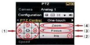
● TVI DVR Coaxial Signal Control and Auto Focus Lens
1) Menu
As shown in Picture:
A. shows the up, down, left and right direction of the menu;
B. shows the enter/confirm button of the menu
2) Lens Auto Focus
shows lens focus (Near/Far) of the Auto focus lens, and (4) shows Zoom(wide/tele) of the AUTO focus lens. When Keep pressing "Focus" or "Zoom" buttons, the lens will keep moving, only after "Focus" or "Zoom" button without pressing, the lens will focus automatically.
MAIN MENU

1 LENS
2 EXPOSURE
3 BACKLIGHT
- WHITE BAL
5 DAY&NIGHT
6 NR
7 SPECIAL
8 ADJUST
9 AF
10 EXIT
MANUAL/DC#
B
OFF/BLC#/HSBLC#
ATM/AWS/ARC-SET/INDOOR/OOTDOOR
AUTO/CO
- 2017年1月1日
1
表
详
SAVE&END#/RESET#/NOT.SAVE#
| LENS | |||
| DC LENS MODE | 1 MODE | INDOOR/OUTDOOR# | |
| 1 MODE | INDUOR | 2 IRIS SPEED | 0-15 |
| 2 IRIS SPEED | INDUOR | 3 RETURN | RET# |
| 3 RETURN | RET | ||
| EXPOSURE | |||
| EXPOSURE | 1 SHUTTER | AUTO/1/30/1/60/FLK/1/240/1/480/1/1000/1/2000/1/5000/1/10000/1/50000/X2/X4/X6/X8/X10/X15/X20/X25/X30 | |
| 1 SHUTTER | AUTO | ||
| 2 AGC | INDUOR | 2 AGC | 0-15 |
| 3 SENS-UP | AUTO | 3 SENS-UP | AUTO# |
| 4 BRIGHTNESS | INDUOR | 4 BRIGHTNESS | 1-100 |
| 5 D-WDR | OFF | 5 D-WDR | OFF/AUTO/ONE |
| 6 DEFOG | OFF | 6 DEFOG | OFF/AUTO# |
| 7 RETURNNL | RET | 7 RETURN | RET# |
| BACKLIGHT | |||
| BLC | 1 LEVEL | MIDDLE/LOW/HICH | |
| 1 LEVEL | MIDDLE | 2 AREA | POSITION/SIZE/RET AGAIN |
| 2 AREA | √ | 3 DEFAULT | # |
| 3 DEFAULT | √ | 4 RETURN | RET# |
| 4 RETURN | RET | ||
| DAY&NIGHT | |||
| 8/N | 1 BURST | OFF/ON | |
| 1 BURET | OFF | 2 IR SMART | OFF/ON# |
| 2 IR SMART | OFF | 3 RETURN | RET# |
| 3 RETURN | RET | ||
| NR | |||
| NR | 1 2DNR | HIGH/MIDDLE/LOW/OFF | |
| 1 ZENR | MIDDLE | 2 3DNR | HIGH/MIDDLE/LOW/OFF |
| 2 ZDNR | MIDDLE | 3 RETURN | RET# |
| 3 RETURN | RET | ||
| SPECIAL | |||
| SPECIAL | 1 CAM TITLE | OFF/ON# | |
| 1 CAN TITLE | ON | 2 D-EFFECT | FREEZE/MIRROR/NEG IMAGE/RETURN |
| 2 D-EFFECT | √ | 3 MOTION | OFF/ON# |
| 3 MOTION | OFF | 4 PRIVACY | OFF/ON# |
| 4 PRIVACY | OFF | 5 LANGUAGE | ENG#/CHN1#/CHN2#/GER#/FRA#/ITAM/SPA#/POL#/RUS#/POR#/NED#/TUR#/KOR#/JPN#/HEB#/ARB# |
| 5 LANGUAGE | ENG | 6 DEFECT | # |
| 6 DEFECT | √ | 7 RS485 | # |
| 7 RS485 | √ | 8 RETUTN | RET# |
| ADJUST | |||
| ADJUST | |||
| 1 SHARPNESS | AUTO | 1 SHARPNESS | OFF/AUTO# |
| 2 MONITOR | LOD | 2 MONITOR | LOD#/CRT# |
| 3 LSG | ON | 3 LSC | OFF/ON |
| 4 VIDEO OUT | PAL | 4 VIDEO OUT | NISC/PAL |
| 5 RETURN | RET | 5 RETURN | RET# |
| AF | |||
| AF | |||
| 1 AF MODE | SEMI | 1 AF MODE | SEMI/AUTO/MANUAL |
| 2 ONE SHOT AF | √ | 2 ONE SHOT AF | # |
| 3 TON AF | ON | 3 TON AF | OFF/ON |
| 4 LENS INIT | √ | 4 LENS INIT | # |
| 5 RETURN | RET | 5 RETURN | RET# |
- Caution for Installation
-
Please do not install the camera where the vibration always happens, or the camera will be damaged.
-
Please keep the glass in front of the camera clean. Do not touch it directly. You can use a soft cloth with alcohol to wipe if necessary.
-
The available IR range of this camera is shown in the specification. Please be sure to place the camera in the working distance when it works.
-
In order to prevent short circuit, please do not loosen any screws in the camera at random.
-
Please do not let the camera work in the conditions which is beyond the most extreme and demanding of operating conditions and climates shown in the specification. When any abnormalities happen, please turn off the camera and contact your local dealer or us right away.
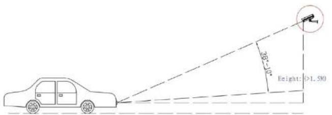
Pay attention to the setting angle. The picture in the right is for your reference.

Installation Guide
(1)

Drill Holes according to the position drawing paper and plug into the rubbers
(2)
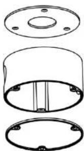
natural_image
Technical line drawing of a cylindrical mechanical component with mounting holes and internal ribs (no text or symbols)Paste the cotton pad on the bottom of junction box, place the water proof rubber ring on the top of the junction box body.
(3)

natural_image
Technical line drawing of a cylindrical component with four protruding pins and four screws, no text or symbols present.Use 3pcs PWA4*25 self-tapping screws to fix the junction box body.
(4)

Use 3pcs KM4*10 machine Screws to fix the round plate on the junction box body.
(5)
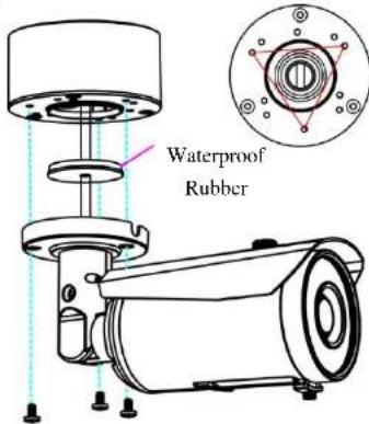
Connect all cable connectors, make the water proof rubber go through the tail of video and power cables;
Put all cables into the junction box body;
Use 3pcs PM4*8 machine screws to fix the camera on the round plate.
(6)

Use allen wrench to loosen the screw on the bullet bracket as picture shown;
Adjust the viewing angle you need, then fasten the screw.
Noting: You can rotate 3 directions freely as picture shown.
Brand : Speco Technologies
Model : HLPR1TW
Category : Camera