
HSNCS70B - Air Conditioning Rinnai - Free user manual and instructions
Find the device manual for free HSNCS70B Rinnai in PDF.


| Product Type | Split System Air Conditioner (Cooling Only) |
| Model | HSNCS70B |
| Indoor Unit Dimensions (W x H x D) | 1186 x 258 x 340 mm |
| Outdoor Unit Dimensions (W x H x D) | 940 x 675 x 399 mm |
| Indoor Unit Weight | 17.0 kg |
| Outdoor Unit Weight | 59.0 kg |
| Power Supply | 230 V / 50 Hz / Single Phase |
| Circuit Breaker Rating | 20 A |
| Refrigerant Type | R32 (Flammable, Class 2.2) |
| Standard Refrigerant Charge | 1420 g |
| Minimum Floor Area for Installation | 1.18 m² |
| Pipe Connection Size (Gas) | 15.88 mm (5/8") |
| Pipe Connection Size (Liquid) | 6.35 mm (1/4") |
| Maximum Pipe Length | 30 m |
| Maximum Height Difference | 20 m |
| Operating Temperature Range (Cool) | Outdoor: 14°C ~ 52°C; Indoor: >17°C |
| Operating Temperature Range (Dry) | Outdoor: 5°C ~ 31°C; Indoor: >6°C |
| Functions | Cool, Dry, Fan, Auto, Sleep, Timer, Follow Me |
| Remote Control | Included with wall bracket and AAA batteries (x2) |
| DRED (Demand Response) Interface | Optional (RJ45 and terminal connections) |
| Filter Cleaning | Removable, washable with mild detergent; turn off power before cleaning |
| Installation Requirements | Must be installed by an Authorised Person in accordance with AS/NZS 3000, AS/NZS 5141 |
| Safety Features | Earth wire, circuit breaker with magnetic and thermal trip, overload protection |
Frequently Asked Questions - HSNCS70B Rinnai
User questions about HSNCS70B Rinnai
0 question about this device. Answer the ones you know or ask your own.
Ask a new question about this device
Download the instructions for your Air Conditioning in PDF format for free! Find your manual HSNCS70B - Rinnai and take your electronic device back in hand. On this page are published all the documents necessary for the use of your device. HSNCS70B by Rinnai.
USER MANUAL HSNCS70B Rinnai
C Series Cooling Only Models:
HSNCS25B
HSNCS34B
HSNCS50B
HSNCS70B
HSNCS80B
natural_image
Line drawing of a Rinnai air conditioner unit (no text or symbols on body)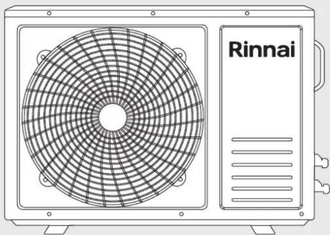
natural_image
Line drawing of a Rinnai air conditioning unit with fan grille and ventilation slots (no text or symbols on the device itself)
Split System Air Conditioner
Installation Manual
Rinnai
This appliance must be installed in accordance with:
• Manufacturer's Installation Instructions
• Current AS/NZS 3000, AS/NZS 5141
- Local Regulations and Municipal Building Codes including local OH&S requirements
This appliance must be installed, maintained and removed only by an Authorised Person.
For continued safety of this appliance it must be installed and maintained in accordance with the manufacturer's instructions.

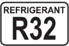
TABLE OF CONTENTS
Warnings and Important Information 4
Installation General 7
Contents Checklist 7
Appliance Components 7
Weights & Dimensions 7
Location 8
Indoor Unit 8
Outdoor Unit 8
Pipe Length & Elevation Limits 8
Installation 9
Indoor Unit 9
Wall Mounting Plate 9
Wall Penetration 9
Drain Pipe 9
Electrical Connections 10
Wall Installation 10
Outdoor Unit 11
Electrical Connections 11
DRED Connection (optional) 12
Refrigerant Pipes 13
Flaring 13
Connecting Vapour / Liquid Pipes To Indoor & Outdoor Units 13
Air Purging & Leakage Test 14
Evacuation Vacuum Method / Leak Test 14
Adding Refrigerant for Longer Line Length 14
Final Checklist 15
WARNINGS AND IMPORTANT INFORMATION

READ ALL INSTRUCTIONS BEFORE USING THE APPLIANCE.
Always comply with the following precautions to avoid dangerous situations and to ensure optimum performance.
Failure to carefully read and follow all instructions in this manual can result in equipment malfunction, property damage, personal injury and/or death.
DANGER: Indicates an imminently hazardous situation which, if not avoided, will result in personal injury or death.
WARNINGS: Indicates a potentially hazardous situation which, if not avoided, could result in personal injury or death.
CAUTIONS: Indicates a potentially hazardous situation which, if not avoided, could result in minor or moderate injury or damage to the appliance. It may also be used to alert against unsafe practices.

REGULATORY
This appliance shall be installed in accordance with:
Manufacturer's Installation Instructions.
Current AS/NZS 3000, AS/NZS 5141.
Local Regulations and Municipal Building Codes including local OH&S requirements.
This appliance must be installed, maintained and removed ONLY by an Authorised Person.
For continued safety of this appliance it must be installed and maintained in accordance with the manufacturers instructions.
This appliance uses R32 refrigerant.
This appliance is heavy, use 2 people or mechanical lifting device. Improper lifting may result in serious injury.
Take care when opening or unpacking this appliance. Failure to do so may result in serious injury or product failure.
DO NOT modify the electrical wiring of this appliance. If the control power wiring is damaged or deteriorated then it must be replaced by an authorised person. Failure to do so may result in electric shock, fire, serious injury or product failure.
DO NOT install the air conditioner on an unstable or non level surface or where there may be a danger of it falling. It may result in death, serious injury, or product failure.
DO NOT install the outdoor unit where noise may cause nuisance.
DO NOT install the outdoor unit where it will be exposed to sea wind (salt spray) as this will reduce durability.

MANDATORY INSPECTION PRIOR TO INSTALLATION
Immediately report any damage or discrepancies to the Supplier of the appliance. This appliance was inspected and tested at the time of manufacture and packaging, and released for transportation without known damage. Upon receipt, inspect the exterior for evidence of rough handling in shipment. Ensure that the appliance is labelled correctly for the gas and electrical supply, and/or other services it is intended to be connected to.
For safety and warranty purposes, appliances that may be damaged or incorrect MUST NOT be installed or operated under any circumstances. Installation of damaged or incorrect appliances may contravene local government regulations. Rinnai disclaims any liability or responsibility whatsoever in relation to the installation or operation of damaged or incorrect appliances.

INSTALLATION
This appliance shall be installed in accordance with local electrical safety regulations by an authorised person such as a licensed electrician.
This appliance is a Type 1 Electrical Appliance.
Make sure the live wire, neutral wire and earth wire in the power socket are properly connected. Inadequate or incorrect electrical connections may cause fire or electric shock.
The yellow-green wire in air conditioner is the earthing wire which cannot be used for other purposes. Improper earthing may cause electric shock.
The circuit breaker must have the functions of magnetic tripping and heat tripping to prevent short circuit and overload.
Use a standard circuit breaker and fuse conforming with the rating of the appliances.
| Model | HSNCS34B HSNCS50B HSNC$70B HSNCS80B | |||
| Circuit Breaker (Amps) | 6 16 20 25 | |||
The unit must be earthed in accordance with local regulations.
Connect all wiring tightly. Failure to do so may result in electric shock or product failure.
DO NOT supply power to the unit until all wiring and tubing are completed.
Select an installation location where the components can be mounted securely and accessible for service and replacement.
Make sure tubing is properly insulated to ensure optimum performance.
Install the drain hose properly for smooth drainage of condensed water.
Make sure to check for and rectify any refrigerant leaks after you install or repair the unit.
This appliance uses R32 (difluoromethane) refrigerant, which is a flammable gas class 2.2 according to AS/NZS 1677 and must be handled by a refrigeration mechanic with appropriate Australian refrigerant handling licence.

WARNING Risk of fire / flammable material. If the refrigerant is leaked, together with an external ignition source, there is a possibility of ignition.

Read the OPERATING INSTRUCTIONS carefully before operation.

Service personnel are required to carefully read the OPERATING INSTRUCTIONS and INSTALLATION MANUAL before operation.

Further information is available in the OPERATING INSTRUCTIONS, INSTALLATION MANUAL, and the like.
Certain levels of refrigerant require minimum room sizes. Please ensure that these minimum room sizes are adhered to for standard installations (up to 10m pipe length). If larger refrigerant charges than standard are used then please consult AS/NZS 60335.2.40 to determine the safe minimum floor area for the installation.
Make sure that the area has been made safe by having suitable ventilation and is free from ignition sources before charging or releasing the charge of R32.
| Model | HSNCS34B HS | NCS50B HSNCS | 70B HSNCS80B | ||
| Standard Charge (g) | 950 1110 1420 1 | 420 | |||
| Minimum Floor Area (m^{2}$ ) | 0.62 | 0.87 | 1.18 | 1.93 | 1.93 |
The minimum floor area ( m^2 ) is determined based on the installation height at 1.8m for wall mounted units.

OPERATION
DO NOT let the air conditioner run for extended periods when the humidity is very high or when doors or windows are left open. As this may result in an excessive operational loading and lead to product failure.
DO NOT cover or place articles on any part of this appliance.
DO NOT touch, operate or clean the air conditioner with wet hands. It may result in electric shock or product failure.
DO NOT insert hands or other objects through the air inlet or outlet while the appliance is operating. It may result in electric shock or product failure.
DO NOT place a heater or other heating appliances near this appliance, always ensure sufficient ventilation when using this appliance and a heating appliance at the same time. Failure to do so may result in product misoperation.
Turn main power off before cleaning. Failure to do so may result in fire, electric shock, or product failure.
DO NOT use solvents, abrasives or harsh detergent to clean any part or surface of this appliance or spray water or allow liquids to enter the indoor unit. The enclosure of the appliance and remote control can be cleaned using a soft, damp cloth and a mild detergent.
NEVER touch the metal parts of the air conditioner when you remove the air filter. It may result in electric shock or product failure.
DO NOT leave flammable materials near the appliance. It may result in explosion or fire.
If there is excessive noise, smell or smoke coming from the appliance, turn the appliance off, isolate the power supply and contact a service agent.
DO NOT operate the appliance if it has been submerged into water due to flooding, contact a service agent. Failure to do so may result in electric shock, fire, serious injury, or product failure.
This appliance is not intended for use by persons (including children) with reduced physical, sensory or mental capabilities, or lack of experience and knowledge unless they have been given supervision or instruction concerning use of the appliance by a person responsible for their safety.
Children should be supervised to ensure that they DO NOT play with the appliance.
The air conditioning system is designed to achieve consumer comfort. It is NOT designed for commercial applications requiring a controlled atmosphere (i.e. computer rooms, food preservation, etc.)
DO NOT block the inlet or outlet of air flow. It may result product in failure.
DO NOT drink the condensate water drained from the appliance. This condensate is not potable and may present a health risk if consumed.
DO NOT expose people, animals or plants directly to the cold or hot discharge of the appliance. It may result in serious injury.
DO NOT mix the batteries for the remote control with other types of batteries or mix new batteries with used batteries. Failure to do so may result in product failure. STOP using the remote control if there is a battery fluid leak.
OPERATION RANGE LIMITATIONS
The table below indicates the temperature ranges the air conditioner can be operated within.
| MODE Cool Mode Dry Mode | ||
| Room Temperature > 17°C > 6°C | ||
| Outdoor Temperature 14°C ~ 52°C 5°C ~ 31°C | ||
INSTALLATION GENERAL
CONTENTS CHECKLIST
| Item and quantity provided(Indoor) | |||||
| Indoor unit x1 Indoor unit support | bracket x1 Operation manual x1 Outdoor unit x1 | ||||
| Remote controller x1 Drain pipe x1 | Installation manual x1 Rubber vibration damper x4 | ||||
| Remote control wall bracket | x1 | Brass nut (small) | x2 | Energy label | x1 |
| AAA battery | x2 | Brass nut (large) | x2 | ||
| Item and quantity provided(Outdoor) | |
| Tape | x1 |
| Putty | x1 |
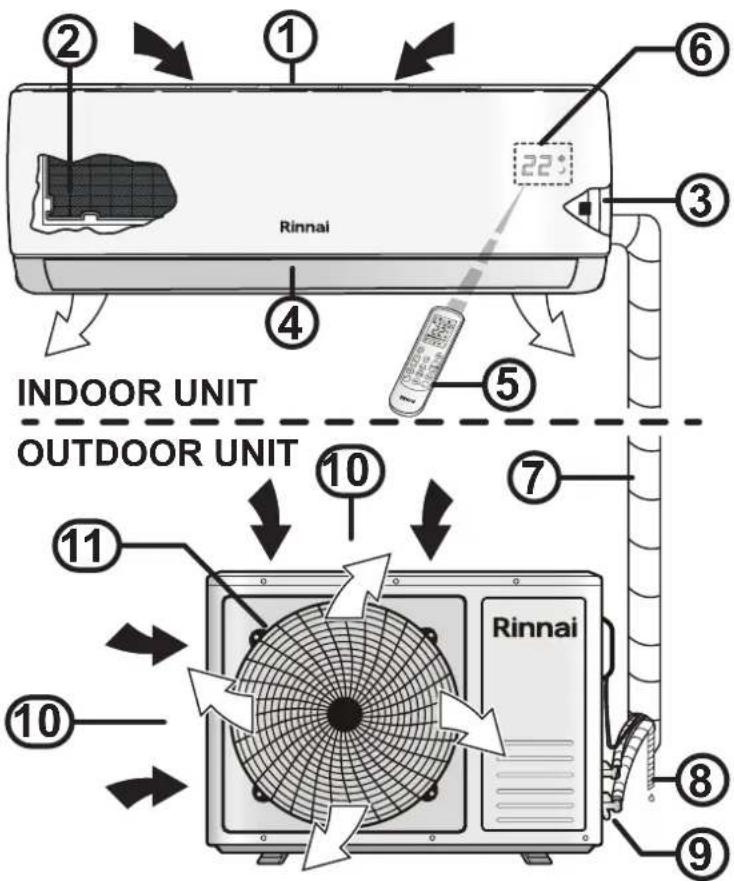
APPLIANCE COMPONENTS
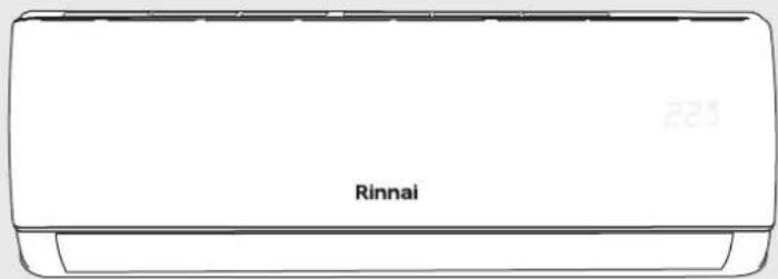
- Indoor unit air inlet
- Filter (located behind front access panel)
- Manual ON/OFF (Auto) override button (located behind front access panel)
- Indoor unit air outlet (with louvres and vanes for setting air flow direction)
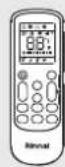
- Remote control
- Signal receiver window and temperature display (the display is built into the front access panel)
- Refrigerant pipes, electrical cable(s) (covered with binding tape)
- Condensate drain hose (covered with binding tape)
- Refrigerant entry (for service and installer use only)
- Outdoor unit air inlet (on rear & left side of unit)
- Outdoor unit air discharge and protective grille (on front of unit)
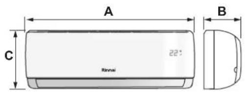
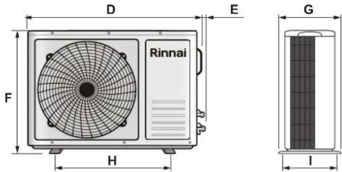
WEIGHTS & DIMENSIONS
| Model | HSNCS25B | HSNCS34B | HSNCS50B | HSNCS70B | HSNCS80B | |||||||||||
| Weight(kg) | Indoor | 9.0 | 13.0 | 17.0 | 17.0 | 17.0 | ||||||||||
| Outdoor | 27.0 | 38.0 | 40.0 | 59.0 | 59.0 | |||||||||||
| Dimensions(mm) | Indoor | A910 | B206 | C294 | A1010 | B220 | C315 | A1186 | B258 | C340 | A1186 | B258 | C340 | A1186 | B258 | C340 |
| Outdoor | D800 | E15 | F553 | D815 | E28 | F602 | D880 | E28 | F699 | D940 | E23 | F808 | D940 | E23 | F808 | |
| G302 | H508 | I278 | G360 | H500 | I328 | G357 | H699 | I329 | G399 | H675 | I378 | G399 | H675 | I378 | ||
LOCATION
INDOOR UNIT
- Ensure the indoor unit is located away from heat or steam.
- Ensure the indoor unit is located so it can be accessed for service and replacement.
- Ensure the indoor unit is located so condensate can be drained away.
- Select a location where the indoor unit can be securely mounted.
- The clearances shown MUST BE maintained.
OUTDOOR UNIT
- Select the location where exposure to direct sunlight and strong wind are minimised.
- Select the location where the outdoor unit can be securely mounted.
- Select the location where the noise and air flow will not cause nuisance.
- Ensure there are no obstructions in the air flow path.
- Ensure the outdoor unit is located so it can be accessed for service and replacement.
- Do not place animals and plants near the air discharge.
- The clearances shown MUST BE maintained.
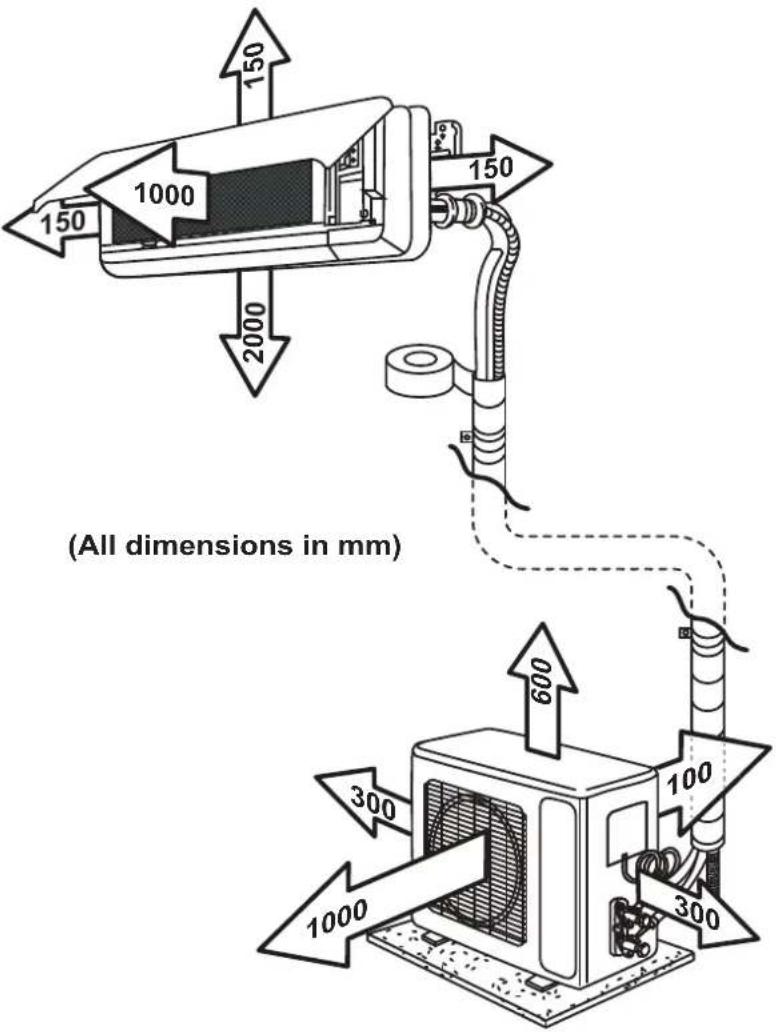
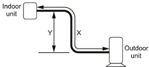
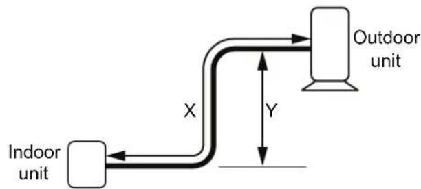
PIPE LENGTH & ELEVATION LIMITS
| Models | Pipe Size Gas Pipe Size Liquid | Chargeless Length | Minimum Length - X | Maximum Length - X | Maximum Height - Y | Additional Refrigerant | |||
| mm inch | mm inch m m | m m g/m | |||||||
| HSNCS25B | 09.52 3/8 06.3 | 35 1/4 10 2 20 | 12 15 | ||||||
| HSNRQ34B | 09.52 3/8 06.3 | 35 1/4 10 2 20 | 12 15 | ||||||
| HSNCS50B | 012.70 1/2 06 | 35 1/4 10 2 30 | 20 25 | ||||||
| HSNCS70B | 015.88 5/8 06 | 35 1/4 10 2 30 | 20 25 | ||||||
| HSNCS80B | 015.88 5/8 06 | 35 1/4 10 2 30 | 20 25 | ||||||

The outdoor unit is charged for interconnecting pipe lengths of up to 10m. Additional refrigerant is to be added for lengths above 10m.
flowchart
graph LR
    A["Indoor unit"] -->|Y| B["Outdoor unit"]
    B -->|X| A
flowchart
graph LR
    A["Indoor unit"] --> B["X"]
    B --> C["Outdoor unit"]
    C --> D["Y"]
INDOOR UNIT
Wall Mounting Plate
- The wall or structure on which the units are to be mounted must be capable of supporting the weight of the appliance and the associated pipe-work.
- Fix the mounting plate on to the wall using, ensuring that it is both level and firmly mounted with the appropriate fixings.

DO NOT install the unit in a place where electrical wiring or conduits are located.
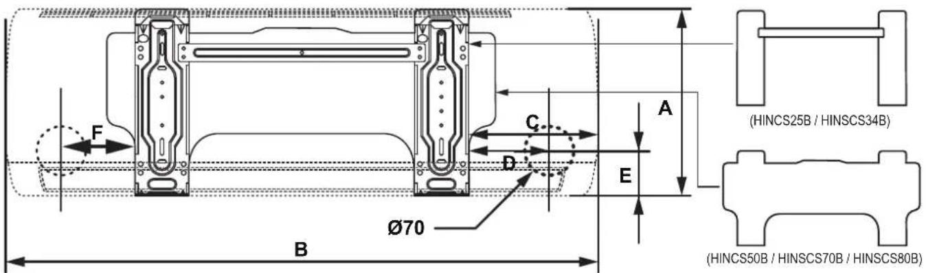
| Wall Mounting Plate Positioning Dimensions (mm) | ||||||||||||||||
| HINCS25B HINCS34B HINC | S50B / HINCS70B / HINCS80B | |||||||||||||||
| A B | C D E F | A B C | D E F A | B C D E F | ||||||||||||
| 294 9 | 10 225 | 170 40 | 150 315 | 1010 2 | 35 180 | 40 120 | 340 118 | 6 265 2 | 05 81 128 | |||||||
Wall Penetration
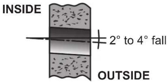
Drill a ∅70mm wall penetration through the wall with a 2° to 4° fall to the outside wall.
Drain Pipe
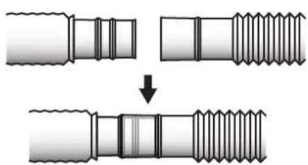
- Connect the drain pipe to the drain hose outlet of the indoor unit,
- Bind the joint with PVC insulation tape (not supplied).
natural_image
Diagram showing two stages of a threaded bolt or screw being welded, with no text or symbols present.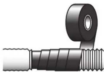
natural_image
Illustration of a mechanical component with threaded end and flange (no text or symbols)Electrical Connections

Must be installed, maintained and removed by authorised persons in accordance with AS/NZS 3000 and all other relevant local regulations and municipal building codes including OH&S requirements.
Ensure electric wiring is installed properly. Improper installation may cause malfunction, fire, or electric shock.
The unit must be earthed following local electrical codes.
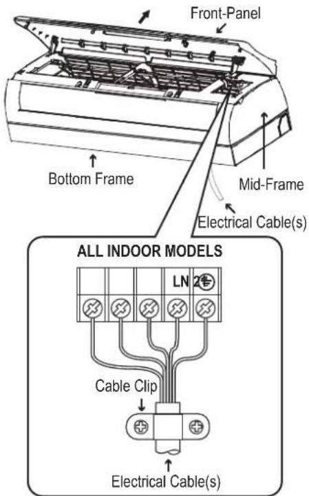
- Open the front panel.
- Remove the wiring cover.
- Insert the electrical cable(s) through the bottom side at the back of indoor unit.
- Secure the cable onto the control board with the cable clip.
- Connect the cables as shown on the drawing to the corresponding terminals.
- Re-install the wiring cover.
- Close the front panel.
Wall Installation
- Remove the two foam shipping blocks from the rear of indoor unit as shown.
- Position the piping as shown on the drawing.
- Tape the refrigerant pipes, electric cable(s) and drain hose. Ensure the water drain hose is located at the lowest side of the bundle.
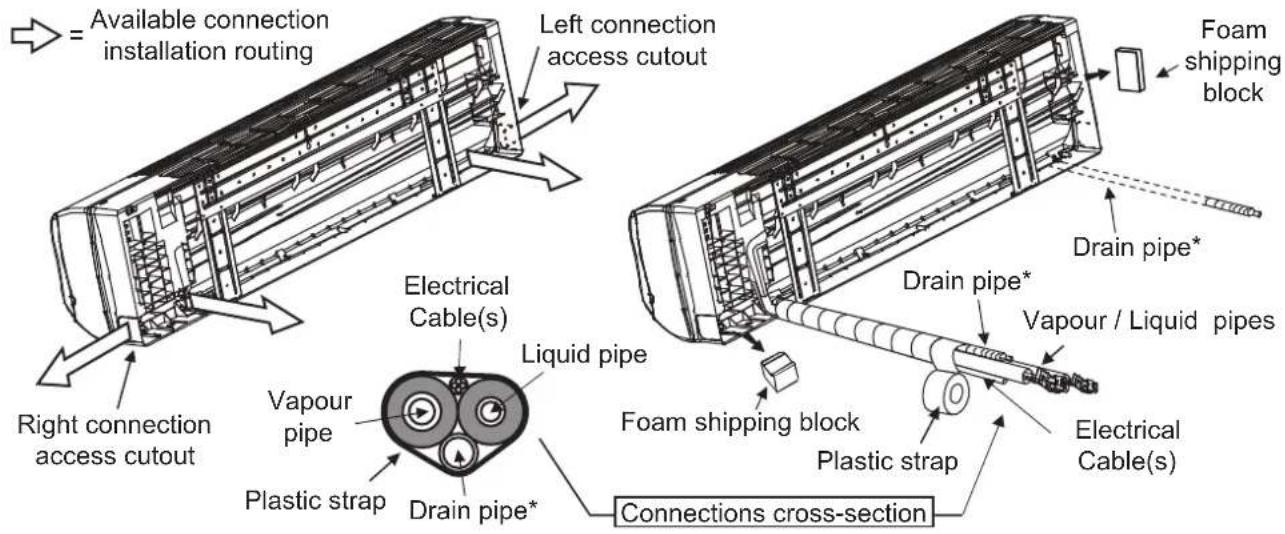

* The drain pipe is dual handed and may be installed to either the left or right of the appliance.
- To use this option unclasp the drain hose.
- Unscrew the rubber plug from the alternate drainage discharge connection point.
- Clip the drainage hose into the alternate discharge connection point.
-
Screw the rubber plug into the unused drainage discharge connection point.
-
Hang the mounting slots of the indoor unit on the upper portion of the mounting plate. Ensure that the hooks are properly seated on the plate.
-
Push the unit towards to the wall, and hook the unit onto the lower fixing hook.
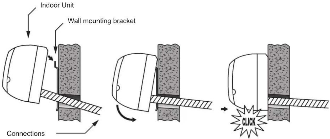

Ensure that there is no leakage from the drain pipe connection and that the drain pipe has a continuous fall to the outside.
Ensure that all wall penetrations are sufficiently weatherproofed.
OUTDOOR UNIT
Electrical Connections

Must be installed, maintained and removed by authorised persons in accordance with AS/NZS 3000 and to all other relevant local regulations and municipal building codes including OH&S requirements.
Ensure electric wiring is installed properly. Improper installation may cause malfunction, fire, or electric shock.
The unit must be earthed following local electrical codes.
- Remove the wiring cover.
- Secure the electrical cable(s) and power cable onto the control board with the cable clip.
- Connect the cables as shown on the drawing below.
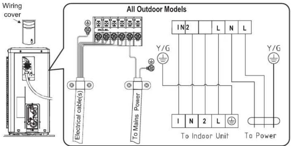
- Re-install the wiring cover.
DRED Connection (optional)
This appliance is supplied with an DRED interface, the interface provides one connection method of an RJ45 socket.

Must be installed, maintained and removed by authorised persons in accordance with AS/NZS 3000 and to all other relevant local regulations and municipal building codes including OH&S requirements.
Ensure electric wiring is installed properly. Improper installation may cause malfunction, fire, or electric shock.
- Remove the wiring cover.
- Connect the power feed to the terminal block as shown on the drawing below.
- Connect the communication cable to DRED interface using either the four wire terminal connections or RJ45 socket provided.
- Re-install the wiring cover.
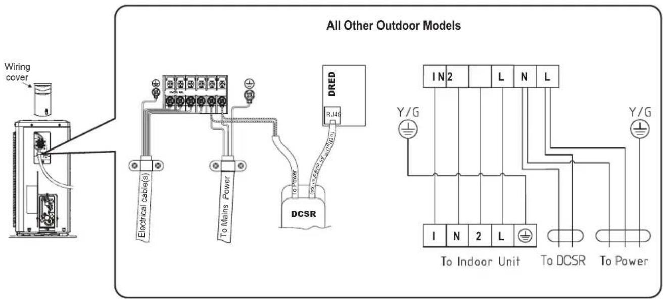
REFRIGERANT PIPES
Flaring

- The main cause for refrigerant leakage is due to defects with the flaring work.
- The installer must ensure that all piping used complies with both:
AS/NZS 1571:1995 - Copper - Seamless tubes for air conditioning and refrigeration. AS/NZS 4041:2006 - Pressure piping. - All pipework and fittings should be thoroughly examined for cleanliness and suitability for the system and refrigerant prior to assembling.
- All unsealed tubing must be thoroughly inspected and, if necessary, cleaned before assembly to remove any copper residue and/or scale particles such as dirt or metal.
- Metal filings must not be left in pipework after cutting as they can cause damage compressor (i.e. shaft seals, bearings, etc.).
- Prior to assembly, refrigeration pipes must be clean and burr free. They must not be crushed or kinked.
- For flare connections, a suitable lubricant must be used between the back of the flare and the nut to avoid tearing the flare when tightening the nut.
Connecting Vapour / Liquid Pipes To Indoor & Outdoor Units
- Align the centre of the pipes.
- Sufficiently tighten the flare nut with fingers, then tighten with a spanner and torque wrench.

To prevent heat loss and wet floors due to dripping of condensation, both pipes must be properly insulated.
| Pipe Dimensions (∅) | Torque Wrench Setting | |
| Metric Imperial | ||
| ∅ 6.35 mm ∅ 1/4" 18 Nm | ||
| ∅ 9.52 mm ∅ 3/8" 42 Nm | ||
| ∅ 12.7 mm ∅ 1/2" 55 Nm | ||
| ∅ 15.88 mm ∅ 5/8" 75 Nm | ||
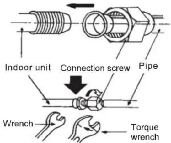
Outdoor UnitIndoor Unit
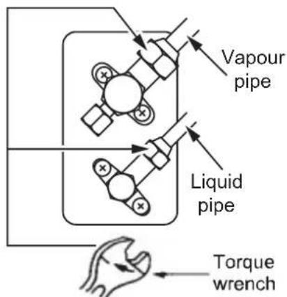

Ensure the joint nut is tightened firmly to avoid leakage.
Ensure that both the connections and the refrigerant pipes are wrapped with insulation material.
Air Purging & Leakage Test

DO NOT mix any substance other than the specified refrigerant (R32) into refrigerant system.
When refrigerant gas leaks occur, ventilate the room immediately.
R32, as well as other refrigerants, should always be recovered and never be released directly into the environment.
Use a vacuum pump for R32 exclusively. Using the same vacuum pump for different refrigerants may damage the vacuum pump or the unit.

It is necessary to purge air and check for gas leakage after piping work is completed.
If using additional refrigerant, perform air purging from the refrigerant pipes and indoor unit using a vacuum pump, then charge additional refrigerant.
Use a hex socket (3/16") to operate the service valves.
All refrigerant pipe joints to be tightened with a torque wrench at the specified torque.
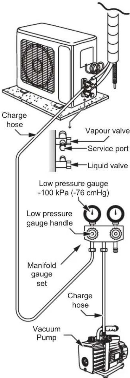
Evacuation Vacuum Method / Leak Test
- Remove the caps from the vapour valve, vapour valve service port and the liquid valve.
- Connect charge hose from the low pressure gauge (manifold gauge set) to the vapour valve service port.
- Open the low pressure gauge valve (manifold gauge set), turn on the vacuum pump and run for a minimum of 15 minutes.
- Close low pressure gauge valve (manifold gauge set) and turn off vacuum pump.
- Wait 2 minutes to allow pressure to stabilise, then check that the low pressure gauge is maintaining a pressure of -100 kPa (-76 cmHg).
- Disconnect charge hose from the vapour valve service port and replace the vapour valve service port cap.
- Open both the vapour and the liquid valves to charge the refrigerant system for test running.
- Test run the system through both heating and cooling cycles and test for leaks.
- Replace the vapour and liquid valve caps.

Both the vapour and liquid valve caps MUST BE on tight.
- The system is now ready to run.
Adding Refrigerant for Longer Line Length
Additional refrigerant for longer piping runs can be added either at the time of evacuation of the new installation or whilst the unit is operating, see "Pipe Length & Elevation Limits" on page 8.

It is very easy to overcharge, take caution in charging refrigerant liquid and keep your eye on the scales to avoid overcharging the unit.
Take care not to discharge refrigerant into the atmosphere during installation, re-installation, repair or service.
FINAL CHECKLIST

The checklist is ONLY to be completed by an Authorised Person.
| Check Item What can happen if not checked | |
| Is the indoor unit installed securely? Falling, vibration, noise | |
| Has an inspection been made to check for gas leakage? No cooling or heating | |
| Has all thermal insulation been completed (vapour pipes, liquid pipes, indoor portions of the drain hose extension)? | |
| Is the drainage secure? Water leakage | |
| Are the electric wires installed correctly? | |
| Is the wiring in accordance within the specifications? Operation failure, electrical fire | |
| Are all inlets / outlets of the indoor and outdoor units free of any obstructions? | |
| Are the stop valves open? No cooling or heating | |
| Are the pipes designed for use with R32? Pipe or pipe connection leakage | |
| Has a leak test been carried out for the pipe connections? Pipe connection leakage | |
| Has air purging been carried out? No cooling or heating | |
| Has the appliance been tested for correct operation? No cooling or heating | |
| Is the end user fully aware of the operating procedure? Incorrect operation | |
If you have answered no to any of the above, you must check and correct before appliance hand-over to customer.
Rinnai Australia Pty Ltd
ABN74005138769 | AU24752
100 Atlantic Drive, Keysborough, Victoria 3173
P.O. Box 460, Braeside, Victoria 3195
Tel: (03) 92716625
Fax: (03) 92716622
National Help Line
Tel: 1300 555 545* Fax: 1300 555 655
Monday to Friday, 8.00 am to 5.00 pm EST.
*Cost of a local call higher from mobile or public phones.
For further information visit www.rinnai.com.au or email enquiry@rinnai.com.au
Rinnai has a Service and Spare Parts network with personnel who are fully trained and equipped to give the best service on your Rinnai appliance. If your appliance requires service, please call our National Help Line. Rinnai recommends that this appliance be serviced every 3 years.
With our policy of continuous improvement, we reserve the right to change, or discontinue at any time, specifications or designs without notice.
- Split System Air Conditioner
- Installation Manual
- TABLE OF CONTENTS
- Warnings and Important Information 4
- Installation General 7
- Location 8
- Installation 9
- WARNINGS AND IMPORTANT INFORMATION
- READ ALL INSTRUCTIONS BEFORE USING THE APPLIANCE.
- REGULATORY
- MANDATORY INSPECTION PRIOR TO INSTALLATION
- INSTALLATION
- OPERATION
- OPERATION RANGE LIMITATIONS
- INSTALLATION GENERAL
- CONTENTS CHECKLIST
- APPLIANCE COMPONENTS
- WEIGHTS & DIMENSIONS
- LOCATION
- INDOOR UNIT
- OUTDOOR UNIT
- Wall Mounting Plate
- Wall Penetration
- Drain Pipe
- Electrical Connections
- Wall Installation
- DRED Connection (optional)
- REFRIGERANT PIPES
- Flaring
- Connecting Vapour / Liquid Pipes To Indoor & Outdoor Units
- Air Purging & Leakage Test
- Evacuation Vacuum Method / Leak Test
- Adding Refrigerant for Longer Line Length
- FINAL CHECKLIST
- Rinnai Australia Pty Ltd
- National Help Line
Brand : Rinnai
Model : HSNCS70B
Category : Air Conditioning