
DINLR20Z7 - Air Conditioning Rinnai - Free user manual and instructions
Find the device manual for free DINLR20Z7 Rinnai in PDF.


| Product Type | Split System Air Conditioner |
| Model | DINLR20Z7 |
| Brand | Rinnai |
| Indoor Unit Dimensions (WxHxD) | 800 x 280 x 200 mm |
| Outdoor Unit Dimensions (WxHxD) | 700 x 550 x 250 mm |
| Indoor Unit Weight | 10 kg |
| Outdoor Unit Weight | 30 kg |
| Power Supply | 220-240 V ~ 50 Hz |
| Cooling Capacity | 2.0 kW (7000 BTU/h) |
| Heating Capacity | 2.5 kW (8500 BTU/h) |
| Refrigerant | R32 |
| Energy Efficiency Ratio (EER) | 3.2 |
| Seasonal Energy Efficiency Ratio (SEER) | 6.5 |
| Noise Level (Indoor) | 25 - 40 dB(A) |
| Noise Level (Outdoor) | 48 - 55 dB(A) |
| Operating Modes | Cool, Heat, Fan, Dehumidify, Auto, Sleep |
| Airflow Direction | Auto swing (vertical and horizontal) |
| Filter Type | Washable fine mesh filter |
| Timer | 24-hour programmable timer |
| Remote Control | Included |
| Installation Type | Wall-mounted indoor unit, outdoor unit on bracket |
| Warranty | 2 years parts and labor |
| Maintenance | Clean filter every 2 weeks; professional service annually |
| Safety Features | Overheating protection, restart delay, self-diagnosis |
| Repairability | Modular design; authorized service centers |
Frequently Asked Questions - DINLR20Z7 Rinnai
User questions about DINLR20Z7 Rinnai
0 question about this device. Answer the ones you know or ask your own.
Ask a new question about this device
Download the instructions for your Air Conditioning in PDF format for free! Find your manual DINLR20Z7 - Rinnai and take your electronic device back in hand. On this page are published all the documents necessary for the use of your device. DINLR20Z7 by Rinnai.
USER MANUAL DINLR20Z7 Rinnai
Outdoor Units Indoor Units
DONSR20Z9 DINLR20Z7
DONSR24Z9 DINLR24Z7

natural_image
Pure technical line drawing of a rectangular mechanical component with mounting flanges (no text or symbols)
natural_image
Technical line drawing of a dual-panel air conditioning unit with ventilation grilles and mounting brackets (no text or symbols)Ducted Reverse Cycle Inverter
Operation & Installation Manual
Rinnai
This appliance must be installed in accordance with:
• Manufacturer's Installation Instructions
• Current AS/NZS 3000, AS/NZS 5141
- Local Regulations and Municipal Building Codes including local OH&S requirements
This appliance must be installed, maintained and removed only by an Authorised Person.
For continued safety of this appliance it must be installed and maintained in accordance with the manufacturer's instructions.

TABLE OF CONTENTS
Warnings and Important Information 4
- Part Names ....8
- Display Panel (Optional) 8
Operation 8
- Before Installation 9
- Maintenance 9
- Symptoms That Are Not Faults ...... 10
- Troubleshooting 10
Warnings and Important Information 13
Installation Indoor 17
- Before Installation 17
- Choosing an Installation Site 17
- Indoor Unit Installation 18
- Refrigerant Piping Installation 21
- Condensate Water Discharge Piping Installation 23
- Duct Installation 25
- Electrical Wiring 27
- On-site Configuration 31
- Test Run 33
Installation Outdoor 34
- Precautions ...... 34
- Attached Fittings ...... 34
- Outdoor Unit Installation 36
- Install The Connecting Pipe ....38
- Electrical Wiring 41
- Test Running 45
- Precautions On Refrigerant Leakage 46
- Turn Over To Customer 46
- Technical Specifications 47
- Cleaning the Indoor Unit 48
- Cleaning the Outdoor Unit 48
- General Maintenance ....48
- Maintenance - Pre-Season Inspection 48
Care & Maintenance 48
- Installation Record - Installer Details 49
- Installation Record - System Details 49
- Customer Care Program 49
- Service Maintenance Schedule - Ducted Air Conditioning Systems 50
- Save A Service Call ....51
- Performing Routine Maintenance .... 53
- Checking The Air Filter 53
- Unit Support 53
- Non-Rinnai Field Supplied Accessories 53
- Disposal Guidelines ....54
Warranty 55
Contacts 60
WARNINGS AND IMPORTANT INFORMATION

READ ALL INSTRUCTIONS BEFORE USING THE APPLIANCE.
Always comply with the following precautions to avoid dangerous situations and to ensure optimum performance.
Failure to carefully read and follow all instructions in this manual can result in equipment malfunction, property damage, water leakage, electric shock, fire, personal injury and/or death.
DANGER: Indicates an imminently hazardous situation which, if not avoided, will result in personal injury or death.
WARNINGS: Indicates a potentially hazardous situation which, if not avoided, could result in personal injury or death.
CAUTIONS: Indicates a potentially hazardous situation which, if not avoided, could result in minor or moderate injury or damage to the appliance. It may also be used to alert against unsafe practices.

ACHIEVING OPTIMAL PERFORMANCE
For optimal performance ensure to use the air conditioner within the following temperature ranges. Using the air conditioner outside of these ranges, will activate certain safety protection features, that will effect the appliances performance.
| MODE COOL MODE | HEAT MODE | |
| Room Temperature 17°C ~ 3 | 2°C 0°C ~ 30°C | |
| Outdoor Temperature -15°C ~ | 50°C -15°C ~ 24°C |
WARRANTY EXCLUSIONS
Rinnai product warranty excludes faults and failures caused by improper use and abuse; fair wear and tear; or failure to follow instructions regarding service and maintenance. It is very important that you maintain your appliance and have it serviced regularly. It is a condition of warranty that you adhere to the maintenance and service requirements as set out in this manual. Compliance with these requirements will prolong the useful life of your appliance and help ensure it operates eff Maintenance Schedule". specifies specific items to be performed at prescribed int licensed technicians. The schedule should also be fully completed and retained as a record of who carried out the service, the date and actions taken.
IMPORTANT: Failure to carry out the requisite maintenance, servicing and recording requirements may void your product warranty. Please refer to "Warranty" for full details.

MANDATORY INSPECTION PRIOR TO INSTALLATION
Immediately report any damage or discrepancies to the Supplier of the appliance. This appliance was inspected and tested at the time of manufacture and packaging, and released for transportation without known damage. Upon receipt, inspect the exterior for evidence of rough handling in shipment. Ensure that the appliance is labelled correctly for the gas and electrical supply, and/or other services it is intended to be connected to.
For safety and warranty purposes, appliances that may be damaged or incorrect must not be installed or operated under any circumstances. Installation of damaged or incorrect appliances may contravene local government regulations. Rinnai disclaims any liability or responsibility whatsoever in relation to the installation or operation of damaged or incorrect appliances.

A NOTE ON ILLUSTRATIONS
The illustrations used in this manual are for explanatory purposes only and the shape of your indoor unit may vary slightly from that which is shown in this manual.

OPERATION / SAFETY
DO NOT use this unit in locations where flammable gas may exist. If flammable gas comes into contact with the unit, a fire may occur, which could result in serious injury or death.
If this unit exhibits any abnormal behaviour (such as emitting smoke) there is a danger of serious injury. Disconnect the power supply and contact your supplier or service engineer immediately.
The refrigerant in this unit is safe and should not leak if the system is designed and installed properly. However, if a large amount of refrigerant leaks into a room, the oxygen concentration will decrease rapidly, which can cause serious injury or death. The refrigerant used in this unit is heavier than air, so the danger is greater in basements or other underground spaces. In the event of a refrigerant leak, turn off any devices that produce a naked flame and any heating devices, ventilate the room, and contact your supplier or service engineer immediately.
Toxic fumes may be produced if the refrigerant in this unit comes into contact with naked flames (such as from a heater, gas stove/burners, or electric appliances).
If this unit is used in the same room as a cooker, stove, hob, or burner, ventilation for sufficient fresh air must be ensured, otherwise the oxygen concentration will fall, which may cause injury.
Dispose of this unit's packaging carefully, so children cannot play with it. Packaging, especially plastic packaging, can be dangerous, can cause serious injury or death. Screws, staples packaging components can be sharp and should be disposed of carefully to avoid injury.
DO NOT attempt to inspect or repair this unit yourself. This unit should only be serviced and maintained by a professional air conditioning service engineer. Incorrect servicing or maintenance can cause electric shocks, fire or water leaks.
This unit should only be re-positioned or re-installed by a professional technician. Incorrect installation can lead to electric shocks, fire or water leaks. The installation and grounding of electrical appliances should only be carried out by licensed professionals. Ask your supplier or installation engineer for further information.
DO NOT allow this unit or its remote controller to come into contact with water, as this can lead to electric shocks or fire.
Turn off the unit before cleaning it to avoid electric shocks. Otherwise, an electric shock and injury may result.
To avoid electric shocks and fires, install an earth leakage detector.
DO NOT use paint, varnish, hair spray, other flammable sprays or other liquids that may give off flammable fumes/vapor near this unit, as doing so can cause fires.
When replacing a fuse, ensure that the new fuse to be installed completely complies with requirements.
DO NOT open or remove the unit's panel when the unit is powered on. Touching the unit's internal components while the unit is powered on can lead to electric shocks or injuries caused by moving parts such as the unit's fan.
Ensure that the power supply is disconnected before any servicing or maintenance is carried out.
DO NOT touch the unit or its remote controller with wet hands, as doing so can lead to electric shocks.
DO NOT allow children to play near this unit, as doing so risks injury.
DO NOT insert your fingers or other objects into the unit's air inlet or air outlet to avoid injury or damage to the equipment.
DO NOT spray any liquids onto the unit or allow any liquids to drip onto the unit.
DO NOT place vases or other liquid containers on the unit or in places where liquid could drip onto it. Water or other liquids that come into contact with the unit can lead to electric shocks or fires.

DO NOT remove the remote controller's front or back overs and DO NOT touch the remote controller's internal components, as doing so can cause injury. If the remote controller stops working, contact your supplier or service engineer.
Ensure that the unit is properly grounded, otherwise electric shocks or a fire may result. Electrical surges (such as those that can be caused by lightning) can damage electrical equipment. Ensure that suitable surge protectors and circuit breakers are properly installed, otherwise electric shocks or a fire may result.
Dispose of this unit properly and in accordance with regulations. If electrical appliances are disposed of in landfills or dumps, hazardous substances can leak into the groundwater and thus enter the food chain.
DO NOT use the unit until the qualified technician instructs you that it is safe to do so.
DO NOT place appliances that produce naked flames in the path of the airflow from the unit. The airflow from the unit may increase the rate of combustion, which may cause a fire and cause serious injury or death. Alternatively, the airflow may cause incomplete combustion which can lead to reduced oxygen concentration in the room, which can cause serious injury or death.

Only use the air conditioner for its intended purpose. This unit should not be used to provide refrigeration or cooling for food, plants, animals, machinery, equipment or art.
DO NOT insert your fingers or other objects into the unit's air inlet or air outlet to avoid injury or damage to the equipment.
The fins on the unit's heat exchanger are sharp and can cause injury if touched. To prevent injury, when the unit is being serviced, gloves should be worn or the heat exchanger should be covered.
DO NOT place items which might be damaged by moisture under the unit. When the humidity is greater than 80% or if the drain pipe is blocked or the air filter is dirty, water could drip from the unit and damage objects placed under the unit.
Ensure that the drain pipe functions properly. If the drain pipe is blocked by dirt or dust, water leaks may occur when the unit is running in cooling mode. If this happens, turn the unit off and contact your supplier or service engineer.
DO NOT TOUCH THE INTERNAL PARTS OF THE CONTROLLER. DO NOT REMOVE the front panel. Some internal parts may cause injury or be damaged.
Ensure that children, plants and animals are not directly exposed to the airflow from the unit.
When fumigating a room with insecticide or other chemicals, cover the unit well and DO NOT run it. Failure to observe this caution could lead to chemicals getting deposited inside the unit and later emitted from the unit when it running, endangering the health of any room occupants.
DO NOT dispose of this product as unsorted waste. It must be separately collected and processed. Ensure that all applicable legislation regarding the disposal of refrigerant, oil and other materials is adhered to. Contact your local waste disposal authority for information about disposal procedures.
To avoid damaging the remote controller, exercise caution when using it and replacing its batteries. DO NOT place objects on top of it.
DO NOT place appliances that have naked flames under or near the unit, as heat from the appliance can damage the unit.
DO NOT place the unit's remote controller in direct sunlight. Direct sunlight can damage the remote controller's display.
DO NOT use strong chemical cleaners to clean the unit, as doing so can damage the unit's display or other surfaces. If the unit is dirty or dusty, use a slightly damp cloth with very diluted and mild detergent to wipe the unit. Then, dry it with a dry cloth.

Children SHALL NOT play with the appliance.
DO NOT dispose of this product as unsorted waste. It must be separately collected and processed. Ensure that all applicable legislation regarding the disposal of refrigerant, oil and other materials is adhered to. Contact your local waste disposal authority for information about disposal procedures.

natural_image
Symbol of a trash bin crossed with no text or numbers, representing waste sorting or disposal (no text present)This appliance is NOT intended for use by persons (including children) with reduced physical, sensory or mental capabilities, or lack of experience and knowledge, unless they have been given supervision or instruction concerning use of the appliance by a person responsible for their safety.
Children should be supervised to ensure that they DO NOT play with the appliance.
This appliance can be used by children aged from 8 years and above and persons with reduced physical, sensory or mental capabilities or lack of experience and knowledge if they have been given supervision or instruction concerning use of the appliance in a safe way and understand the hazards involved. Children shall not play with the appliance. Cleaning and user maintenance shall not be made by children without supervision.
OPERATION
1. PART NAMES
The drawing shown below (Figure 1) is for reference only and may be slightly different from the actual product.

Figure 1.
2. DISPLAY PANEL (OPTIONAL)
The display panel has one type and the appearance of the type is shown in Figure 2.

Figure 2.
Table 1. Display panel output under normal operating conditions
| Unit state | Display output | ||
| Digital display panels | |||
| Unit State Digital display | |||
| Standby | Operation indicator flashes slowly |  | |
| Shutting-down All indicators off |  | ||
| Operation | Normal operation | Operation indicator on | Cooling and heating modes: set temperature Fan only mode: indoor ambient temperature |
| Cold draft prevention or outdoor unit defrosting operation | Operation and Anti-cold / defrosting indicators on | Set temperature | |
| A timer has been set Timer indicator on | |||
* The display panel should be installed in the ceiling, nothing can be exposed but the panel face
3. BEFORE INSTALLATION
The operating temperature range under which the unit runs stably are given in Table 2 below.
Table 2.
| Mode Indoor temperature | |
| Cooling | 17-32°CIf the indoor humidity is above 80%, condensation may form on the surf ace of the unit. |
| Heating ≤ 27°C | |

The unit performs stably in the temperature range given in above table. If the indoor temperature is outside the unit's normal operating range, it may stop running and display an error code.
To ensure the desired temperature is achieved efficiently, ensure that:
- All windows and door are closed.
• The airflow direction is adjusted to work in running mode.
• The air filter is clean.
Please note how you can best save energy and achieve the best cooling/heating effect.
- Regularly clean air filters inside indoor units.
Avoid too much outdoor air coming into air-conditioned spaces.


Note that outlet air is cooler or warmer than set room temperature. Avoid direct exposure to outlet air as it may be too cool or hot.

Maintain a proper air distribution. Air outlet louvers should be used to adjust the direction of outlet airflow, as doing so might ensure more efficient operation.

natural_image
Simple line drawing of a woman standing next to a baby with a spiral symbol above her head (no text or symbols present)4. MAINTENANCE

Please release pressure before disassembly.
Before you clean the air conditioner, ensure it is powered off.
Check that the wiring is undamaged and connected.
Use a dry cloth to wipe the indoor unit and controller.
A wet cloth may be used to clean the indoor unit if it is very dirty.
Never use a damp cloth on the controller.
Do not use a chemically treated duster on the unit or leave this type of material on the unit to avoid damaging the finish.
Do not use benzene, thinner, polishing powder, or similar solvents for cleaning. These may cause the plastic surface to crack or warp.
4.1 Maintenance after a long period of non-use
(a) Check for and remove anything that might be blocking the inlet and outlet vents of the indoor units and outdoor units.
(b) Turn on the power at least 12 hours before you want to use the unit to ensure it works properly. As soon as the power is turned on, the control display appears.

When the power switch is connected, some energy will be consumed even if the unit is not running. Disconnect the power to save energy.
A degree of dirt will accumulate when the unit has been used several times, which will require cleaning.
Take of the batteries from the remote controller.
5. SYMPTOMS THAT ARE NOT FAULTS
The following symptoms may be experienced during the normal operation of the unit and are not considered faults.
Note: If you are not sure whether a fault has occurred, contact your supplier or service engineer immediately.
Symptom 1. The unit will not run
Symptom: When the ON/OFF button on the controller is pressed, the unit does not immediately start running.
Cause: to protect certain system components, system start-up or re-start is intentionally delayed for up to 12 minutes under some operating conditions. If the OPERATION LED on the unit's panel is lighting, the system is working normally and the unit will start after the intentional delay is complete.
Heating mode is running when the following panel lights are on: operation and the "DEF./FAN LED" indicator.
Cause: the indoor unit activates protective measures because of the low outlet temperature.
Symptom 2. Symptom 2: The unit emits white mist
White mist is generated and emitted when the unit starts to operate in a very humid environment. This phenomenon will stop once the humidity in the room is reduced to normal levels.
The unit occasionally emits white mist when it runs in heating mode. This occurs when the system finishes periodic defrosting. Moisture that may accumulate on the unit's heat exchanger coil during defrosting becomes mist and is emitted from the unit.
Symptom 3. Symptom 4: Dust is emitted from the unit
This can occur when the unit first runs after a long idle period.
Symptom 4. Symptom 5: The unit gives off a strange odour
If smells such as those of strong-smelling food or tobacco smoke are present in the room, they can enter the unit, leave trace deposits on the unit's internal components, and later be emitted from the unit.
6. TROUBLESHOOTING
6.1 General
Sections “6.2 Unit Troubleshooting” on page 11 and “6.3 Remote Controller Troubleshooting” on describe some initial troubleshooting steps that can be taken when an error occurs. If these steps do not resolve the issue, arrange for a professional technician to investigate the problem. Do not attempt further investigations or troubleshooting yourself.
(a) If any of the following errors occur, power the unit off, contact a professional technician immediately and do not attempt troubleshooting yourself:
(b) A safety device such as a fuse or circuit breaker frequently blows/trips.
(c) An object or water enters the unit.
(d) Water is leaking from the unit.

Do not attempt to inspect or repair this unit by yourself. Arrange for a qualified technician to carry out all servicing and maintenance.
6.2 Unit Troubleshooting
Table 3.
| Symptom Possible causes | Troubleshooting steps | |
| The unit does not start | A power cut has occurred (the power to the premises has been cut-off). | Wait for the power to come back on. |
| The unit is powered off. | Power on the unit. Ask a professional technician for advice regarding how to safely power on the units. | |
| The power switch fuse may have burned out. | Replace the fuse reset circuit breaker. | |
| Air flows normally but doesn't cool The temperature setting is not correct. | Set the desired temperature on the remote controller. | |
| The unit starts or stops frequently | Arrange for a professional technician to check the following:Too much or too little refrigerant.No gas in the refrigerant circuit.The outdoor unit compressors have malfunctioned.The power supply voltage is too high or too low.There is a blockage in the piping system. | |
| Low cooling effect | Doors or windows are open. Close the doors and windows. | |
| Sunlight is shining directly onto the unit. | Close shutters/blinds to shield the unit from direct sunlight. | |
| The room contains many heat sources such as computers or refrigerators. | Turn off some of the computers during the hottest part of the day. | |
| The outside temperature is unusually high. | The cooling capacity of the system reduces as the outdoor temperature rises and the system may not provide sufficient cooling if the local climate conditions are not considered when the system's outdoor units were selected. | |
| Engage a professional air conditioning engineer to check the following:The unit's heat exchanger is dirty.The unit's air inlet or outlet is blocked.A refrigerant leak has occurred. | ||
| Low heating effect | Doors or windows are not completely closed. | Close doors and windows. |
| Arrange for a professional technician to check the following:A refrigerant leak has occurred. | ||
6.3 Remote Controller Troubleshooting

Certain troubleshooting steps that a professional technician may perform when investigating an error are described in this operation manual for reference only. Do not attempt to undertake these steps yourself – arrange for a professional technician to investigate the problem. If any of the following errors occur, power the unit off and contact a professional technician immediately. Do not attempt troubleshooting yourself:
- A safety device such as a fuse or circuit breaker frequently blows/trips.
- An object or water enters the unit.
• Water is leaking from the unit.
Table 4.
| Symptom Possible causes | Troubleshooting steps | |
| The fan speed cannot be adjusted | Check whether the MODE indicated on the display is “AUTO”. | In automatic mode, the air conditioner will automatically change the fan's speed. |
| Check whether the MODE indicated on the display is “DRY”. | When dry mode is selected, the air conditioner automatically adjusts the fan speed. (The fan speed can be selected during “COOL”, “FAN ONLY”, and “HEAT”.) | |
| The remote controller signal is not transmitted even when the ON/OFF button is pushed | A power cut has occurred (the power to the premises has been cut-off). | Wait for the power to come back on. |
| The indication on the display disappears after a certain time | Check whether the timer operation has come to an end when TIMER OFF is indicated on the display. | The air conditioner operation will stop up to the set time. |
| The TIMER ON indicator goes off after a certain time | Check whether the timer operation has come to an end when TIMER ON is indicated on the display. | Up to the set time, the air conditioner will automatically start and the appropriate indicator will go off. |
| No receiving sound from the indoor unit when the ON/OFF button is pressed | Check whether the signal transmitter of the remote controller is properly directed to the infrared signal receiver of the indoor unit when the ON/OFF button is pressed. | Directly transmit the signal transmitter of the remote controller to the infrared signal receiver of the indoor unit, and then press the ON/OFF button twice. |
6.5 Error Codes
With the exception of a mode conflict error, contact your supplier or service engineer if any of the error codes listed in the following table are displayed on the unit's display panel. If the mode conflict error is displayed and persists, contact your supplier or service engineer. These errors should only be investigated by a professional technician. The descriptions are provided in this manual for reference only.
Table 5.
| Content Display output Possible causes | ||
| Mode conflict E0 The indoor unit operating mode conflicts with that of the | outdoor units. | |
| Communication error between indoor and outdoor units | E1 Communication | wires between indoor and outdoor units not connected properly.Interference from high voltage wires or other sources of electromagnetic radiation.Communication wire too long.Damaged main PCB. |
| Indoor ambient temperature sensor (T1) error | E2 • Temperature | sensor not connected properly or has malfunctioned.Damaged main PCB. |
| Indoor heat exchanger mid-point temperature sensor (T2) error | E3 | |
| Indoor heat exchanger outlet temperature sensor (T2B) error | E4 | |
| Fan error E6 • Fan stuck or blocked. | • Fan motor not connected properly or has malfunctioned.Power supply abnormal.Damaged main PCB. | |
| EEPROM error E7 • Damaged main PCB. | ||
| Indoor EEV coil error Eb • Line loosened or broken. | • The electronic expansion• Damaged main PCB. | |
| Outdoor unit error Ed • Outdoor unit error. | ||
| Water level error EE • Water level float stuck. | • Water level switch not connected properly.Damaged main PCB.Drain pump has malfunctioned. | |
| The indoor unit has not been assigned an address | FE | • Indoor unit has not been assigned an address. |
WARNINGS AND IMPORTANT INFORMATION

READ ALL INSTRUCTIONS BEFORE USING THE APPLIANCE.
Always comply with the following precautions to avoid dangerous situations and to ensure optimum performance.
Failure to carefully read and follow all instructions in this manual can result in equipment malfunction, property damage, water leakage, electric shock, fire, personal injury and/or death.
DANGER: Indicates an imminently hazardous situation which, if not avoided, will result in personal injury or death.
WARNINGS: Indicates a potentially hazardous situation which, if not avoided, could result in personal injury or death.
CAUTIONS: Indicates a potentially hazardous situation which, if not avoided, could result in minor or moderate injury or damage to the appliance. It may also be used to alert against unsafe practices.

REGULATORY / INSTALLATION
This appliance shall be installed in accordance with:
Manufacturer's Installation Instructions.
Current AS/NZS 3000, AS/NZS 5141.
Local Regulations and Municipal Building Codes including local OH&S requirements.
This appliance must be installed, maintained and removed by an Authorised Person. Refrain from doing it yourself. Improper installation may cause water leakage, electric shock or fire.
For continued safety of this appliance it must be installed and maintained in accordance with the manufacturers instructions.
This appliance uses R410A refrigerant.
This appliance is heavy, use 2 people or mechanical lifting device. Improper lifting may result in serious injury.
Take care when opening or unpacking this appliance. Failure to do so may result in serious injury product failure.
DO NOT modify the electrical wiring of this appliance. If the control power wiring is damaged or deteriorated then it must be replaced by an authorised person. Failure to do so may result in electric shock, fire, serious injury or product failure.
DO NOT install the air conditioner on an unstable or non level surface or where there may be a danger of it falling. It may result in death, serious injury, or product failure.
DO NOT install the outdoor unit where noise may cause nuisance.
DO NOT install the outdoor unit where it will be exposed to sea wind (salt spray) as this will reduce durability.

MANDATORY INSPECTION PRIOR TO INSTALLATION
Immediately report any damage or discrepancies to the Supplier of the appliance. This appliance was inspected and tested at the time of manufacture and packaging, and released for transportation without known damage. Upon receipt, inspect the exterior for evidence of rough handling in shipment. Ensure that the appliance is labelled correctly for the gas and electrical supply, and/or other services it is intended to be connected to.
For safety and warranty purposes, appliances that may be damaged or incorrect MUST NOT be installed or operated under any circumstances. Installation of damaged or incorrect appliances may contravene local government regulations. Rinnai disclaims any liability or responsibility whatsoever in relation to the installation or operation of damaged or incorrect appliances.

INSTALLATION / SAFETY
For installation in smaller rooms, you must adopt the relevant measures to prevent the refrigerant concentration from exceeding the limit. Please consult the sales agent on the relevant measures required. A high concentration of refrigerant in an airtight space can cause oxygen insufficiency (anoxia).
Make sure the required parts and accessories are installed. Using unspecified parts may cause the air conditioner to malfunction or drop, as well as water leakage, electric shock, and fire.
Mount the air conditioner in a place that is sturdy enough to bear its weight. If the base is not secured properly, the air conditioner may drop leading to damages and injuries.
Take in full consideration to the effects of strong winds, storms and earthquakes, and installation. Improper installation may cause the air conditioner to drop leading to accidents.
Make sure a standalone circuit is used for the power supply. All electrical parts must comply with the local laws and regulations, and what is stated in this installation manual. The installation works must be carried out by a professional and qualified electrician. Insufficient capacity or improper electrical works can lead to electric shock or fire.
Use only electrical cables that fulfil the specifications. All wiring on site must be carried out in accordance with the connection diagram attached to the product. Make sure that there are no external forces acting on the terminals and wires. Improper wiring and installation may cause a fire.
Make sure the power cord, communication and controller wiring are straight and level when you are working on the connections, and the cover on the electric box is tight. If the electric box is not closed properly, it may lead to electric shock, fire or overheating of electrical components.
If the refrigerant leaks during installation, open the doors and windows immediately to ventilate the area. Refrigerant can produce toxic gases when in contact with fire.
Switch off the power supply before touching any electrical component.
DO NOT come in direct contact with the refrigerant leaking from the connections of refrigerant piping. Otherwise, it may lead to frostbite.
The air conditioner must be grounded. DO NOT connect the earth line (ground) to gas piping, water piping, lightning rods or telephone earth lines. Improper grounding can lead to electric shock or fire, and may cause mechanical failure due to current surges from lightning and so on.
The earth leakage circuit breaker must be installed. There is a risk of electric shock or fire if the earth leakage circuit breaker is not installed.
Install the water discharge piping according to the steps described in this manual, and make sure that the water discharge is smooth, and the piping is properly insulated to prevent condensation. Improper installation of the water discharge piping may lead to water leakage, and damage the indoor furniture.
If the supply cord is damaged, it must be replaced by the manufacturer or its service agent or a similarly qualified person in order to avoid a hazard.
An all-pole disconnection switch having a contact separation of at least 3mm in all poles should be connected in fixed wiring.
The temperature of refrigerant circuit will be high, please keep the interconnection cable away from the copper tube.
Check the power supply before installation. Ensure that the power supply must be reliably grounded following local, state and National Electrical Codes. If not, for example, if the ground wire is charged, installation is prohibited before it is rectified. Otherwise, there is a risk of fire and electric shock, causing physical injury or death.

Install the water discharge piping according to the steps described in this manual, and make sure that the water discharge is smooth, and the piping is properly insulated to prevent condensation. Improper installation of the water discharge piping may lead to water leakage, and damage the indoor furniture.

When mounting the indoor and outdoor units, make sure the power cord is installed at a distance of at least 1 m away from any TV or radio so as to prevent noise or interference with the images.
The refrigerant required for the installation is R410A. Make sure the refrigerant is correct before installation. Incorrect refrigerant may cause the unit to malfunction.
DO NOT install the air conditioner in the following places:
- Where there is oil or gas, such as the kitchen. Otherwise, the plastic parts may age prematurely or water may leak.
- Where there are corrosive gases (such as sulphur dioxide). Corrosion in the copper pipes or welded parts may cause the refrigerant to leak.
- Where there are machines emitting electromagnetic waves. Electromagnetic waves may interfere with the control system, causing the unit to malfunction.
- Where there is a high salt content in the air. When exposed to air with a high salt content, the mechanical parts will experience accelerated ageing which will severely compromise the service life of the unit.
- Where there are major voltage fluctuations. Operating the unit using a power supply system that has large voltage fluctuations will reduce the service life of the electronic components, and cause the unit's controller system to malfunction.
- Where there is a risk of leakage of flammable gases. Examples are sites that contain carbon fibres or combustible dust in the air, or where there are volatile combustibles (such as diluent or petrol). The above gases may cause explosion and fire.
• DO NOT touch the fins of the heat exchanger as this may lead to injury. - Some products use the PP packing belt. DO NOT pull or tug on the PP packing belt when you transport the product. It will be dangerous if the packing belt breaks.
- Note the recycling requirements for nails, wood, carton and other packaging materials. DO NOT discard these materials directly as these may lead to bodily harm.
- Tear up the packaging bag for recycling to prevent children from playing with it, and leading to suffocation.
• The appliance shall not be installed in the laundry.

OPERATION
DO NOT let the air conditioner run for extended periods when the humidity is very high or when doors or windows are left open. As this may result in an excessive operational loading and lead to product failure.
DO NOT cover or place articles on any part of this appliance.
DO NOT touch, operate or clean the air conditioner with wet hands. It may result in electric shock or product failure.
DO NOT insert hands or other objects through the air inlet or outlet of the appliance it may result in electric shock or product failure.
DO NOT place a heater or other heating appliances near this appliance, always ensure sufficient ventilation when using this appliance and a heating appliance at the same time. Failure to do so may result in product miss-operation.
Turn main power off before cleaning. Failure to do so may result in fire, electric shock, or product failure.
DO NOT use solvents, abrasives or harsh detergent to clean any part or surface of this appliance or spray water or allow liquids to enter the indoor unit. The enclosure of the appliance and remote control can be cleaned using a soft, damp cloth and a mild detergent.
NEVER touch the metal parts of the air conditioner when you remove the air filter. It may result in electric shock or product failure.
DO NOT leave flammable materials near the appliance. It may result in explosion or fire.
If there is excessive noise, smell or smoke coming from the appliance, turn the appliance OFF, isolate the power supply and contact a service agent.
DO NOT operate the appliance if it has been submerged into water due to flooding, contact a service agent. Failure to do so may result in electric shock, fire, serious injury, or product failure.
This appliance is NOT intended for use by persons (including children) with reduced physical, sensory or mental capabilities, or lack of experience and knowledge unless they have been given supervision or instruction concerning use of the appliance by a person responsible for their safety.
Children should be supervised to ensure that they DO NOT play with the appliance.
The air conditioning system is designed to achieve consumer comfort. It is not designed for commercial applications requiring a controlled atmosphere (i.e. computer rooms, food preservation, etc.)
DO NOT block the inlet or outlet of air flow. It may result product failure.
DO NOT drink the condensate water drained from the appliance. This condensate is not potable and may present a health risk if consumed.
DO NOT expose people, animals or plants directly to the cold or hot discharge of the appliance. It may result in serious injury.
DO NOT mix the batteries for the remote control with other types of batteries or mix new batteries with used batteries. Failure to do so may result in product failure. STOP using the remote control if there is a battery fluid leak.
DO NOT use an extension cord, manually extend the power cord, or connect other appliances to the same outlet as the air conditioner. Poor electrical connections, poor insulation, and insufficient voltage can cause fire.
ACCESSORIES
| CODE | NAME OF ACCESSORIES QTY OUTLINE USAGE | ||||
| 1 | Installation manual 1 (This manual) – | ||||
| 2 | Operation manual 1 | [###] | – | ||
| 3 | Pipe insulation material 7.1-28.0kW 2 | [###] | Heat insulation | ||
| 4 | Water connecting pipe 20.0-24.0kW 2 | [###] | To connect drain pipe | ||
| 5 | Adhesive tape for seal 20.0-24.0kW 2 | [###] | To connect drain pipe | ||
| 6 | Display | 1 | [###] | – | |
| 7 | Weak electric cable group | 1 |  | – | |
| 8 | Copper nut | 2 |  | Use for connecting pipes | |
| CODE | NAME | APPEARANCE | DIMENSIONS | QTY | NOTE |
| 1 | Thermostat control wire (shielded cable 0.75mm) |  | To purchase based on actual project requirements. | To purchase based on actual project requirements. | Use to connect to wired controller. |
| 2 | Copper pipe | Choose and purchase copper pipes that correspond to the length and size calculated for the selected model in the installation manual of the outdoor unit and your actual project requirements. | To purchase based on actual project requirements. | Use to connect indoor refrigerant piping. | |
| 3 | PVC pipe for water discharge |  | Refer to specific models. | To purchase based on actual project requirements. | Use to discharge condensed water from the indoor unit. |
| 4 | Insulation casing for piping |  | The inner diameter is based on the diameter of the copper and PVC pipes. The thickness of the pipe casing is 10 mm or more. Increase the thickness of the casing (20 mm or thicker) when the temperature exceeds 30°C or the humidity exceeds RH80%. | To purchase based on actual project requirements. | Protect piping from condensation. |
| 5 | Expansion hook anchor |  | M10 | To purchase based on actual project requirements. | For installation of indoor unit. |
| 6 | Mounting hook |  | M10 | To purchase based on actual project requirements. | For installation of indoor unit. |
| 7 | Tie |  | To purchase based on actual project requirements. | To purchase based on actual project requirements. | Tie for connecting wire |
| 8 | Safety tray |  | Based on install | To purchase based on actual project requirements. | Prevent ceiling damage. |
7. BEFORE INSTALLATION
- Determine the route to move the unit to the installation site.
- First unseal and unpack the unit. Then hold the four seats of the hanger to move the unit. Refrain from exerting force on other parts of the unit, especially the refrigerant piping, water discharge piping, and plastic parts.
8. CHOOSING AN INSTALLATION SITE
8.1 Choose a site that fully complies with the following conditions and user requirements to install the air conditioning unit.
- Well ventilated.
• Unobstructed airflow.
• Strong enough to bear the weight of the indoor unit.
• Ceiling has no obvious slant.
- There is sufficient space for repair and maintenance work to be carried out.
• No leakage of flammable gas.
- The length of the piping between the indoor and outdoor units is within the permitted range (refer to the manual on installation of the outdoor unit).
- The static pressure of the air duct of the indoor unit is within the permitted range (see "12.2 Fan Performance" on page 26).

If the indoor ambient temperature and relative humidity exceed 30^ C and 80%, attach insulation materials at a thickness greater than 10 mm to the unit body.
8.2 Install with M10 or W3/8 lifting bolts.
8.3 The space required for installation (unit: mm) is shown in Figure 3 and Figure 4 below.


Figure 3. Figure 4.
9. INDOOR UNIT INSTALLATION
Make sure that only specified components are used for the installation works.
9.1 Installation with Lifting Bolts
Use different bolts for the installation depending on the installation environment.


Figure 5. Wooden structure Figure 6. Original concrete slab structure
Directly set and use an angled steel rod for support.

Set using embedded appliances, and embedded type of bolts.

Figure 7. Steel framework Figure 8. Newly set concrete slab structure

All bolts should be made from high quality carbon steel (with galvanized surface or other rust prevention treatment) or stainless steel.
How the ceiling should be handled will differ with the type of building. For specific measures, please consult the building and renovation engineers.
How the lifting bolt is secured depends on the specific situation, and it must be secure and reliable.
9.2 Installation of the Indoor Unit
- When mounting the lifting lugs of the indoor unit on the lifting bolts, slot the nut washers of the lifting bolts in the oblong holes of the lifting lugs. The upper and lower nuts and the washers are shown in Figure 9.
- Adjust the height of the indoor unit.
- Use a spirit level to verify that the unit body is level (making the unit body slope downwards towards the drainage side), as shown in Figure 10.


Figure 9. Steel framework Figure 10. Newly set concrete slab structure
20.0-24.0 KW UNIT

10. REFRIGERANT PIPING INSTALLATION
10.1 Length and Level Difference Requirements for the Piping Connections to the Indoor and Outdoor Units
The length and level difference requirements for the refrigerant piping are different for different indoor and outdoor units. Refer to the installation manual of the outdoor unit.
10.2 Piping Material and Size
- Piping material: Copper pipes.
- Piping size: Choose and purchase copper pipes that correspond to the length and size calculated for the selected model in the installation manual of the outdoor unit and your actual project requirements.
10.3 Piping Layout
- Seal the two ends of the piping properly before you connect the indoor and outdoor piping. Once unsealed, connect the piping of the indoor and outdoor units as quickly as possible to prevent dust or other debris from entering the piping system via the unsealed ends, as this may cause the system to malfunction.
- If the piping needs to go through walls, drill the opening in the wall, and place accessories like casings and covers for the opening properly.
- Place the refrigerant connecting piping and the communication wiring for the indoor and outdoor units together, and bundle them tightly to make sure air does not enter and condensate to form water that may leak from the system.
- Insert the bundled piping and wiring from outside the room through the wall opening into the room. Be careful when you lay out the piping. Do not damage the piping.
10.4 Piping Installation
- Refer to the installation manual attached with the outdoor unit on installation of the refrigerant piping for the outdoor unit.
- All gas and liquid piping must be properly insulated; otherwise, this may cause water to leak. Use heat insulation materials that can withstand high temperatures above 120^ C to insulate the gas pipes. In addition, the insulation of the refrigerant piping should be reinforced (20 mm or thicker) in situations where there is high temperature and/or high humidity (when part of refrigerant piping part is higher than 30^ C or when the humidity exceeds RH80%). Otherwise, the surface of the heat insulation material may be exposed.
- Before the works are carried out, verify that the refrigerant is R410A. If the wrong refrigerant is used, the unit may malfunction.
- Other than the specified refrigerant, do not let air or other gases enter the refrigeration circuit.
- If the refrigerant leaks during installation, make sure you fully ventilate the room.
- Use two wrenches when you install or dismantle the piping, a common wrench and a torque wrench. See Figure 4.1.

Figure 12.
- Slide the refrigerant piping into the brass nut (accessory), and expand the pipe socket. Refer to the following table for the size of the pipe socket and the appropriate tightening torque.
Table 6. Tightening torque
| External diameter(mm) | Tightening torque Flared opening diameter (A) | Flared opening |
| 6.5 14.2-17.2N·m 8.3-8.7mm | 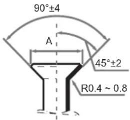 Figure 13. Figure 13. | |
| 9.53 32.7-39.9N·m 12-12.4mm | ||
| 12.7 49.5-60.3N·m 15.4-15.8mm | ||
| 15.9 61.8-75.4N·m 18.6-19mm | ||
| 19.1 97.2-118.6N·m 22.9-23.3mm |

Apply the appropriate tightening torque according to the installation conditions. Excessive torque will damage the socket cap, and the cap will not be tight if you apply insufficient torque, leading to leakages.
Before the flare nut is installed on the pipe, apply some refrigerant oil on the flare (both inside and outside), and then rotate it three or four times before you tighten the nut. See Figure 14.

Figure 14.

Precautions to take when welding the refrigerant pipes
- Before you weld the refrigerant pipes, fill the pipes with nitrogen first to discharge the air in the pipes. If no nitrogen is filled during welding, a large amount of oxide film will form inside the piping which may cause the air conditioning system to malfunction.
- Welding can be carried out on the refrigerant pipes when the nitrogen gas has been replaced or refilled.
- When the pipe is filled with nitrogen during welding, the nitrogen must be reduced to 0.02 MPa using the pressure release valve. See Figure 15.

Figure 15.
| 1 | Copper piping |
| 2 | Section being brazed |
| 3 | Nitrogen connection |
| 4 | Hand valve |
| 5 | Pressure-reducing valve |
| 6 | Nitrogen |
10.5 Pressure Test
Carry out the air tightness test on the system according to the instructions in the installation manual of the outdoor unit.

The Pressure Test helps to ensure that the air and liquid cut-off valves of the outdoor unit are all closed (maintain the factory defaults).
10.6 Heat Insulation Treatment for Gas-Liquid Piping Connections for the Indoor Unit
- The heat insulation treatment is carried out on the piping at the gas and liquid sides of the indoor unit respectively.
(a) The piping on the gas side must use heat insulation material that can withstand temperatures of 120^ C and more.
(b) For the piping connections of the indoor unit, use the insulation casing for copper pipes (accessory) to carry out the insulation treatment, and close all gaps.

Figure 16.
10.7 Vacuum
Create a vacuum in the system according to the instructions in the installation manual of the outdoor unit.

For the vacuum, make sure that the cut-off valves of the outdoor unit are all closed (maintain the factory status).
10.8 Refrigerant
Charge the system with refrigerant according to the instructions in the installation manual of the outdoor unit.
11. CONDENSATE WATER DISCHARGE PIPING INSTALLATION
11.1 Condensate water Discharge Piping Installation for Indoor Unit
- Use PVC pipes for the water discharge pipes. Based on the installation scenario, users can purchase the appropriate piping length from a sales agent, local after-sales service centre, or local market. The piping length should be at least the same length as the body of the unit.
- Insert the water discharge pipe into the end of the water suction connecting pipe of the unit body, and use the ring clamp (accessory) to clamp the water discharge pipes with the insulation casing for the water outlet piping securely.
- Use the insulation casing for water discharge piping (accessory) to bundle the water suction and discharge pipes of the indoor unit (especially the indoor portion), and use the tie for the water discharge piping (accessory) to bind them firmly to make sure air does not enter and condense.
- In order to prevent the back-flow of water into the interior of the air conditioner when the operation stops, the water discharge pipe should slope downwards towards the outside (drainage side) at a slope of more than 1/100. Make sure that the water discharge pipe does not swell or store water; otherwise, it will cause strange noises. See Figure 17.

Figure 17.
- When connecting the water discharge piping, do not use force to pull the pipes to prevent the water suction pipe connections from coming loose. At the same time, set a supporting point at every 0.8\~1 m to prevent the water discharge pipes from bending. See Figure 17.
- When connecting to a long water discharge pipe, the connections must be covered with the insulation casing to prevent the long pipe from coming loose.
- Install the water discharge pipes as shown in Figure 18 (without a water pump) and Figure 19 (with a water pump). The water discharge piping outlet should not be higher than the water discharge height, ensuring a downward slope of more than 1/100.

Water discharge pipes from multiple units are connected to the main water discharge pipe to be discharged through the sewage pipe.

Water discharge pipes from multiple units are connected to the main water discharge pipe to be discharged through the sewage pipe.
Figure 18. Without water pump (standard) Figure 19. With water pump (optional)
- The end of the water discharge pipe must be more than 50 mm above the ground or from the base of the water discharge slot. Besides, do not put it in the water.
- Install the water storage elbow.
(a) For a water discharge duct connected to the main drain pan in the indoor unit, the water discharge piping must include a water storage elbow to prevent loading pressure from building up and causing poor water drainage, water leaks, or water being discharged out of the air outlet duct when the indoor unit is running.
(b) In a scenario where the indoor unit runs continuously for long periods (48 hours or more), continuous operations, or where the relative humidity of the air is 85% or higher, connect the water discharge piping of the secondary drain pan to the main water discharge piping, and then install the water storage elbow. Install the water storage elbow as shown in Figure 20. Install it in such a way that it is easy to clean.

Figure 20. Schematic of water storage elbow
11.2 Water Discharge Test
Before the test, make sure that the water discharge pipeline is smooth, and check that each connection is sealed properly. Conduct the water discharge test in the new room before the ceiling is installed.
Indoor unit without a drainage pump
- Use a bottle or similar vessel to place about 2 litres of water into the drain pan.
- Check that the water discharge piping outlet discharge water properly (based on the length of the pipe, the discharge may occur at a delay of 1 minute or so), and check for water leakages at each joint.

Figure 21. Verify water discharge
12. DUCT INSTALLATION
12.1 Design and Installation
- In order to prevent short-circuit air delivery, the duct for air outlet and air return ducts must not be too close.
- The indoor unit does not have an air filter installed. The air filter must be installed at a location like an air inlet where it can be easily maintained. (Without an air filter, dust particles may stick to the coil which will make the air conditioner prone to failures and water leakage.)
- Before installing the duct, ensure that the static pressure of the duct is within the permitted range of the indoor unit. Refer to "12.2 Fan Performance" on page 26.
- Connect the canvas duct to the air return and air outlet ducts to prevent vibrations from the indoor unit transferring to the ceiling.
- Use insulation materials at a thickness of 25 mm or more to prevent condensation on the air duct.
- Connect the air duct as shown in Figure 22.

Figure 22.

On-site preparation required for all components except for the air conditioner.

Once the air conditioner body and the canvas joints are riveted together, the upper flange plate must be secured with screws.
(M6 x 12 screws are prepared on site.)
12.2 Fan Performance
20.0-24.0kW

- Set proper external static pressure (ESP) according to the actual installation conditions. Otherwise it may cause some problems.
- If the connecting duct is long and the ESP setting is low, the airflow will be very low, leading to poor performance.
- If the connecting duct is short and the ESP setting is high, the airflow will be very high, leading to higher operating noise and even water may be blown out through the air outlet.
- ESP can be set through the DIP switch SW2 on the main board or the new wired controller. Please refer to Part "8.3 DIP switch settings on main board" for SW2 setting or the wired controller manual for wired controller setting.
Table 7. Four ESP can be set through DIP switch SW2.
| Capacity ESP1 ESP2 ESP3 ESP4 | ||||
| 20.0-24.0kW 170Pa | 100Pa 200Pa 250Pa | |||
Table 8. Twenty ESP can be set through the new wired controller
| Capacity20.0-24.0kW | 00 01 | 02 03 | 04 05 | 06 07 | 08 09 | 10 11 | 12 | 13 14 | 15 16 | 17 18 | 19 | ||||||||||
| 30Pa | 50Pa | 60Pa | 70Pa | 80Pa | 90Pa | 100Pa | 110Pa | 120Pa | 130Pa | 140Pa | 150Pa | 160Pa | 170Pa | 180Pa | 190Pa | 200Pa | 210Pa | 230Pa | 250Pa |
13. ELECTRICAL WIRING

All the supplied parts, materials and electrical works must comply with local regulations.
Use only copper wires.
Use a dedicated power supply for the air-conditioners. The power voltage must be in line with the rated voltage.
The electrical wiring works must be carried out by a professional technician, and must comply with the labels stated in the circuit diagram.
Before the electrical connection works are carried out, turn off the power supply to prevent injuries caused by electric shock.
The external power supply circuit of the air conditioner must include an earth line, and the earth line of the power cord connecting to the indoor unit must be securely connected to the earth line of the external power supply.
Leakage protection devices must be configured according to the local technical standards and requirements for electrical and electronic devices.
The fixed wiring connected must be equipped with an all-pole disconnection device with a minimum 3 mm contact separation.
The distance between the power cord and signalling line must be at least 300 mm to prevent the occurrences of electrical interference, malfunction or damage to electrical components. At the same time, these line must not come in contact with the piping and valves.
Choose electrical wiring that conforms to the corresponding electrical requirements.
Connect to the power supply only after all the wiring and connection works have been completed, and carefully checked to be correct.
13.1 Power Cord Connection
- Use a dedicated power supply for the indoor unit that is different from the power supply for the outdoor unit.
- Use the same power supply, circuit breaker and leakage protection device for the indoor units connected to the same outdoor unit.


Figure 23. Figure 24. Power supply terminal of the
indoor unit
When connecting to the power supply terminal, use the circular wiring terminal with the insulation casing. See Figure 25.
Use power cord that conforms to the specifications and connect the power cord firmly. To prevent the cord from being pulled out by external force, make sure it is fixed securely.
If circular wiring terminal with the insulation casing cannot be used, please make sure that:
Do not connect two power cords with different diameters to the same power supply terminal (may cause overheating of wires). See Figure 26.

Figure 25. Figure 26. Power supply terminal of the indoor unit
13.2 Electrical Wiring Specifications

flowchart
graph TD
    A["Breakers with current leakage"] --> B["Switch (breakers for wiring and over current protection)"]
    B --> C["All-pole disconnection device with leakage protection"]
    C --> D["Indoor unit"]
    E["220-240V~50Hz\n220-240V~50/60Hz\nPower supply"] --> A
Figure 27.
Refer to Table 4 and Table 5 for the specifications of the power cord and communication wire. A wiring capacity that is too small will cause the electrical wiring to become too hot, and lead to accidents/damage.
Table 9. Indoor Unit
| Model | ||
| Power supply Phase | 1-phase | |
| Volt and frequency 220-240V~50Hz220-240V~50/60Hz | ||
| Communication wire between indoor and outdoor units Shield 3×AWG16-AWG20 | ||
| Communication wire between indoor unit and wired controller Shield AWG16-AWG20 | ||
| Field fuses / breaker 15A | ||
* Please refer to the corresponding wired controller manual for the wired controller wiring.
Table 10.
| Model name Power | supply IFM | |||||
| Hz Volts M | CA MFA kW | FLA | ||||
| 20.0kW | 50/60 | 220-240 | 6.7 | 15 | 0.8 | 5.4 |
| 24.0kW | 50/60 | 220-240 | 6.7 | 15 | 0.92 | 5.4 |
Abbreviations:
MCA: Minimum Circuit Amps
IFM: Indoor Fan Motor
FLA: Full Load Amps
MFA: Maximum Fuse Amps
kW: Rated motor output
- Select the wire diameters (minimum value) individually for each unit based on the Table 11, where the rated current in Table 11 means MCA in Table 10 on page 28.
- Maximum allowable voltage range variation between phases is 2%.
- Select circuit breaker that having a contact separation in all poles not less than 3 mm providing full disconnection, where MFA is used to select the current circuit breakers and residual current operation breakers.
Table 11.
| Rated current of appliance (A) | Nominal cross-sectional area ( mm^2 ) | |
| Flexible cords Cable | for fixed wiring | |
| and ≤3 0.5 and | 0.75 1 and 2.5 | |
| >3 and ≤6 0.75 and 1 1 | and 2.5 | |
| >6 and ≤10 1 and 1.5 1 | and 2.5 | |
| >10 and ≤16 1.5 and 2.5 | 1.5 and 4 | |
| >16 and ≤25 2.5 and 4 | 2.5 and 6 | |
| >25 and ≤32 4 and 6 4 | and 10 | |
| >32 and ≤50 6 and 10 6 | and 16 | |
| >50 and ≤63 10 and 16 | 10 and 25 | |

Refer to local laws and regulations when deciding on the dimensions for the power cords and wiring. Get a professional to select and install the wiring.
13.3 Communication Wiring
- Use only shielded wires for the communication wiring. Any other type of wires may produce a signal interference that will cause the units to malfunction.
- Do not carry out works like welding with the power on.
- All shielded wiring in the network are interconnected, and will eventually connect to earth at the same point “ ⊕”.
- Do not bind the refrigerant piping, power cords and communication wiring together. When the power cord and communication wiring are parallel, the distance between the two lines must be 300 mm or more in order to prevent signal source interference.
- Communication wiring must not form a closed loop.
Communication wiring between the indoor and outdoor units
- The indoor and outdoor units communicate via the RS485 serial port.
- The communication wiring between the indoor and outdoor units should connect one unit after another in a daisy chain from the outdoor unit to the indoor unit, and the shielded layer must be properly grounded, and a build-out resistor must be added to the indoor unit to enhance the stability of the communication system. Refer to Figure 28 on page 30.
- Incorrect wiring such as a star connection or a closed ring will cause instability of the communication system and system control anomalies.
- Use a three core shielded wire (greater than or equal to 0.75 mm ^2 ) for the communication wiring between the indoor and outdoor units. Make sure the wiring is connected correctly. The connecting lead for this communication wire must come from the master outdoor unit.

Figure 28.
Communication wiring between the indoor unit and wired controller
The wired controller and the indoor unit can be connected in different manners, depending on the forms of communication.
1. For a bidirectional communication mode:
Use 1 wired controller to control 1 indoor unit or 2 wired controllers (one master and one slave controller) to control 1 indoor unit. See Figure 29.

flowchart
graph TD
    A["Indoor unit 1"] -->|X1 X2| B["Wired Controller 1"]
    A -->|X1 X2| C["Master wired controller"]
    D["Slave wired controller"] -->|X1 X2| E["Wired Controller 2"]

flowchart
graph TD
    A["Indoor unit 1"] --> B["Display Board"]
    B --> C["Wired Controller 1"]
    C --> B
Figure 29. Figure 30.
2. For a unidirectional communication mode:
Use 1 wired controller to control 1 indoor unit. See Figure 30.
- The X1, X2, D1, D2 ports on the sides of the main control board and the unidirectional communication port (display board side) are for different types of wired controllers. See Figure 31.
- Use the connecting wires (accessory 8) to connect the D1, D2 ports.

Figure 31.

For the specific connection method, refer to the instructions in the corresponding wired controller manual to carry out the wiring and connections.
13.4 Handling the Electrical Wiring Connection Points
- Once the wiring and connections are done, use tie straps to secure the wiring properly so that the connection joint cannot be pulled apart by external force. The connection wiring must be straight out so that the cover of the electrical box is level and can be closed tightly.
- Use professional insulation and sealing materials to seal and protect the perforated wires. Poor sealing may lead to condensation, and entry of small animals and insects that may cause short circuits in parts of the electrical system, causing the system to fail.
14. ON-SITE CONFIGURATION
14.1 Capacity Settings
Set up the PCB DIP switch on the indoor electric control box to cater to different uses. Once the settings are done, make sure you cut off the main power switch again, and then switch the power on. If the power is not cut off and switched on again, the settings will not be executed.
Table 12.
| ENC1 + SW7 | |
| Toggle switch Set cooling capacity | |
| Dial code Cooling capacity | |
| E 20000W | |
| F 24000W | |

Figure 32.

The capacity DIP switches have been configured before delivery. Only a professional maintenance personnel should change these settings.
14.2 Address Settings
When this indoor unit is connected to the outdoor unit, the outdoor unit will automatically allocate the address to the indoor unit. Alternatively, you may use the controller to manually set the address.
- The network address and the indoor unit address are the same, and does not have to be configured separately.
- Once the address settings are completed, mark the address of the indoor unit to facilitate after-sales maintenance.
- The centralised control of the indoor unit is completed on the outdoor unit. For details, refer to the manual on the outdoor unit.

Once the centralised control function for the indoor unit has been completed on the outdoor unit, the DIP switch on main control panel of the outdoor unit must be set to auto addressing; otherwise, the indoor unit in the system are not controlled by the centralized controller.
14.3 8.3 DIP Switch Settings on Main Board
| SW1_1 SW2 | ||
| SW1[0] |  | Cooling mode temperature compensation is 0°C |
| SW1[1] |  | Cooling mode temperature compensation is 2°C |
| SW2[00] |  | External static pressure 1 |
| SW2[01] |  | External static pressure 2 |
| SW1_2 SW2 | ||
| SW1[0] |  | EEV at position 96 (steps) in standby in heating mode |
| SW1[1] |  | EEV at position 72 (steps) in standby in heating mode |
| [10] |  | External static pressure 3 |
| SW2[11] |  | External static pressure 4 |
| Capacity ESP | P1 | ESP2 | ESP3 | ESP4 | ||
| 24.0kW | 170 | Pa | 100Pa | 200Pa | 250Pa |
| SW3_1 SW3_2 | ||
| SW3[0] |  | Reserved |
| SW3[1] |  | Clear indoor unit address |
| SW3[0] | [w668] | Reserved |
| SW4 SW5 | ||
| SW4[00] |  | In heating mode when the set temperature has been reached, the fan operates in a 4 minutes off / 1 minute on repeating cycle |
| SW4[01] | [STC2] | In heating mode when the set temperature has been reached, the fan operates in an 8 minutes off / 1 minute on repeating cycle |
| SW4[10] |  | In heating mode when the set temperature has been reached, the fan operates in a 12 minutes off / 1 minute on repeating cycle |
| SW4[011] | [CGZX] | In heating mode when the set temperature has been reached, the fan operates in a 16 minutes off / 1 minute on repeating cycle |
| SW5[00] |  | In heating mode fan does not run when indoor heat exchanger mid-point temperature is 15°C or below |
| SW5[01] |  | In heating mode fan does not run when indoor heat exchanger mid-point temperature is 20°C or below |
| SW5[10] |  | In heating mode fan does not run when indoor heat exchanger mid-point temperature is 24°C or below |
| SW5[011] |  | In heating mode fan does not run when indoor heat exchanger mid-point temperature is 26°C or below |
| SW6 | ||
| SW6[00] |  | Heating mode temperature compensation is 6°C |
| SW6[01] |  | Heating mode temperature compensation is 2°C |
| SW6[10] |  | Heating mode temperature compensation is 4°C |
| SW6[011] |  | Heating mode temperature compensation is 0°C(use follow me function) |

All DIP switches (including the capacity DIP switch) have been configured before delivery. Only a professional maintenance personnel should change these settings.
Improper DIP switch settings may cause condensation, noise, or unexpected system malfunction.
The default DIP switch setting is based on the actual unit.
| SW7_1 | ||||
| SW7[0] |  | Reserved | ||
| SW7_2 | ||||
| SW7[0] |  | Unit with capacity less than 28kW | ||
| J1 | ||||
| [###] | Auto restart function enabled | |||
| [###] | Auto restart function disabled | |||
| 0/1 definition of each dial code switch | ||||
| means 0 me | ### 1 | |||
14.4 Error Codes and Definitions
| Error Code Content | |
| E0 Mode conflict | |
| E1 Communication error | between indoor and outdoor units |
| E2 Indoor ambient temperature sensor (T1) error | |
| E3 Indoor heat exchanger | mid-point temperature sensor (T2) error |
| E4 Indoor heat exchanger | outlet temperature sensor (T2B) error |
| E6 Fan error | |
| E7 EEPROM error | |
| Eb Indoor EEV coil error | |
| Ed Outdoor unit error | |
| EE Water level error | |
| FE Indoor unit has not been assigned an address | |
15. TEST RUN
15.1 Things to Note Before Test Run
- Indoor and outdoor units are properly installed;
- Piping and wiring are correct;
- No leakage from the refrigerant piping system;
- Water discharge is smooth and free without blockages
- Insulation is complete;
- Grounding line has been properly connected;
- Piping length, and amount of refrigerant filled have been recorded;
- The voltage of the power supply is the same as the rated voltage of the air conditioner;
- No obstacles at the air inlet and outlet of the indoor and outdoor units;
- Cut-off valves for the gas and liquid ends are opened;
- Connect to the power supply to let the air conditioner warm up first.
15.2 Test Run
Use wired/remote controller to control and operate the air conditioner in the cooling mode. Check the following items according to the manual. If there is any fault, troubleshoot by referring to the section "Remote Controller Troubleshooting" on page 11 in the manual.
Indoor unit
- Wired/remote controller switch is operating normally;
- Function keys of the wired/remote controller are operating normally;
- Room temperature regulation is normal;
- LED indicator is on;
- Key for manual operation is normal;
- Water discharge is normal;
- No vibration and strange sounds during operation;
Outdoor unit
- No vibration and strange sounds during operation;
- If the wind, noise and condensation affect the neighbours;
- Any refrigerant leakage.

Once the power is connected, when the unit is turned on or started immediately after the unit is turned off, the air conditioner has a protective function which delays the start of the compressor by 3 minutes.
INSTALLATION OUTDOOR
16. PRECAUTIONS
- Ensure that all Local, National and International regulations are satisfied.
- Read this "PRECAUTIONS" carefully before Installation.
- The precautions described below include the important items regarding safety. Observe them without fail.
• After the installation work, perform a trial operation to check for any problem. - Follow the Owner's Manual to explain how to use and maintain the unit to the customer.
- Turn off the main power supply switch (or breaker) before maintenance the unit.
- Ask the customer to retain in a safe place the Installation and Operational Manual.

NEW REFRIGERANT AIR CONDITIONER INSTALLATION
THIS AIR CONDITIONER ADOPTS THE NEW HFC REFRIGERANT(R410A)WHICH DOES NOT DESTROY OZONE LAYER.
The characteristics of R410A refrigerant are; Hydrophilic, oxidizing membrane or oil, and its pressure is approx.1.6 times higher than that of refrigerant R22. Accompanied with the new refrigerant, refrigerating oil has also been changed. Therefore, during installation work, be sure that water, dust, former refrigerant, or refrigerating oil does not enter the refrigeration cycle.
To prevent charging an incorrect refrigerant and refrigerating oil, the sizes of connecting sections of charging port of the main unit and installation tools are charged from those for the conventional refrigerant.
Accordingly the exclusive tools are required for the new refrigerant (R410A):
- For connecting pipes, use new and clean piping designed for R410A, and please care so that water or dust does not enter.
• Moreover, do not use the existing piping because there are problems with pressure-resistance force and impurity in it.

DO NOT CONNECT THE APPLIANCE FROM MAIN POWER SUPPLY.
This unit must be connected to the main power supply by means of a switch with a contact separation of at least 3 mm.
The installation fuse must be used for the power supply line of this conditioner.
17. ATTACHED FITTINGS
Please check whether the following fittings are of full scope. If there are some spare fittings, please restore them carefully.
INSTALLATION FITTINGS
| CODE N | AME OF ACCESSORIES QTY OUTLINE | ||
| 1 Water outlet connection pipe 1 |  | ||
| 2 Straight screwdriver 1 |  | ||
| 3 Sealing ring 2 |  | ||
| 4 Waterproof chassis cover 2 |  | ||
| 5 Connection pipe (26kW) 2 | [8BY3] | ||
| 6 Curved connection pipe (26kW) 1 |  | ||
REFRIGERANT PIPING
Piping kit used for the conventional refrigerant cannot be used.
Use copper pipe with 0.8 mm or more thickness for 9.5 mm.
Use copper pipe with 1.0 mm or more thickness for 15.9 mm.
Use copper pipe with 1.0 mm or more thickness for 19.0 mm.
Flare nut and flare works are also different from those of the conventional refrigerant. Take out the flare nut attached to the main unit of the air conditioner, and use it.
BEFORE INSTALLATION
Be careful to the following items before installation.
AIR PURGE
For air purge, use a vacuum pump.
Do not use refrigerant charged in the outdoor unit for air purge.
(The refrigerant for air purge is not contained in the outdoor unit.)
ELECTRICAL CABLING
Be sure to fix the power cables and indoor/outdoor connecting cables with clamps so that they do not contact with the cabinet, etc.
INSTALLATION PLACE
A place which provides a specified space around the outdoor unit.
A place where the operation noise and discharged air do not disturb your neighbours.
A place that is not exposed to a strong wind.
A place that does not block a passage.
When the outdoor unit is installed in an elevated position, make sure it's four feet are securely installed.
There must be sufficient space for carrying in the unit.
A place where the drain water does not cause any hazards.

Install the outdoor unit at a place where discharge air is not blocked.
When an outdoor unit is installed in a place that is always exposed to a strong wind like a coast or on a high storey of a building, secure a normal fan operation by using a duct or a wind shield.
When installing the outdoor unit in a place that is constantly exposed to a strong wind such as the upper stairs or rooftop of a building, apply the wind-proof measures referring to the following examples.
- Install the unit so that its discharge port faces to the wall of the building. Keep a distance 1000mm or more between the unit and the wall surface.
- Do not mount the outdoor unit on a wall.
- Set the unit at right angles to any strong prevailing winds
Installation in the following places may result in difficulties.
Do not install the unit in such places below
• A place full of machine oil.
• A place full of sulphuric gas.
- A place where high-frequency radio waves are likely to be generated as from audio equipment, welders, and medical equipment.


18. OUTDOOR UNIT INSTALLATION
18.1 Installation place
- Please keep away from the following locations, or malfunction of the machine may be caused:
• There is combustible gas leakage.
• There is much oil (including engine oil) ingredient.
• There is salty air surrounding(near the coast)
- There is caustic gas (sulfide, for example) existing in the air.
- A place the heat air expelled out from the outdoor unit can reach your neighbour's window.
• A place that the noise interferes your neighbours.
• A place that is too weak to bear the weight of the unit
- Uneven place.
• Insufficient ventilation place.
- Near a private power station or high frequency equipment.
- Install indoor unit, outdoor unit, power cord and connecting wire at least 1m away from TV set or radio to prevent noise or picture interference.
- The insulation of the metal parts of the building and the air conditioner should comply with the regulation of National Electric Standard.

Keep indoor unit, outdoor unit, power supply wiring and transmission wiring at least 1 meter away from televisions and radios. This is to prevent image interference and noise in those electrical appliances. (Noise may be generated depending on the conditions under which the electric wave is generated, even if 1 meter is kept.)
18.2 Installation space (Unit:mm)


Figure 33.

Figure 34. Parallel connect the two units or above

Figure 35. Parallel connect the front with rear sides
18.3 Moving and installation
- Since the centre of gravity the unit is not at its physical centre, so please be careful when lifting it with a sling.
- Never hold the inlet of the outdoor unit to prevent it from deforming.
- Do not touch the fan with hands or other objects.
- Do not lean it more than 45^ , and do not lay it down.
- Make concrete foundation according to the specifications of the outdoor units. Refer to Figure 36.
- Fasten the feet of this unit with bolts firmly to prevent it from collapsing in case of earthquake or strong wind. Refer to Figure 36.

Figure 36.

All illustrations used in this manual are for explanatory purposes only. They may vary slightly from the air conditioner you purchased (depending on the model). The actual unit shape shall prevail.
18.4 Centralised Chassis Drainage
When the outdoor unit requires centralised drainage, install the chassis and two waterproof covers for the chassis, as shown in Figure 37. Install the water outlet union pipe and sealing ring on the chassis, and then connect the drainage pipe to complete centralised drainage installation.

Figure 37.

While installing the outdoor unit, pay attention to the installation place and the drainage pattern; if it's installed at the alpine zone, the frozen condensed water will block up the water outlet, please pull out the rubber stopper of the reserve water outlet. If that still fails to satisfy for the water draining, please knock open the other two water outlets, to allow the water to drain.
Pay attention to the knockout the reserve water outlet from outside to inside, as it will be beyond repair after knocking open. Please pay attention to the installation place, lest cause inconvenience. Please vermin proof for the knocked out hole, to avoid the pest ingress and damage to the components.
19. INSTALL THE CONNECTING PIPE
Check whether the height drop between the indoor unit and outdoor unit, the length of refrigerant pipe, and the number of the bends meet the following requirements:

natural_image
Technical line drawing of a multi-chamber HVAC unit with airflow indicators and internal components (no text or symbols)Figure 38.
19.1 Refrigerant piping

Please pay attention to avoid damage to the components while attaching to the connecting pipes. To prevent the refrigerant piping from oxidizing inside when welding, it is necessary to charge nitrogen, or oxide will block the refrigeration system.
The indoor and outdoor connecting pipe interface and power line outlet
Various piping and wiring patterns can be selected, such as out from the front, the back the side, and underneath, etc. The following figure shows the locations of several piping and wiring knock-off interfaces.
Front out pipe

natural_image
Simple line drawing of a washing machine inside a circular frame (no text or symbols)Side out pipe

natural_image
Simple line drawing of a kitchen appliance inside a circular frame (no text or symbols)Figure 39.

- Side out pipe: cut the side hole of the pipe-outlet plate selectively. It is suggested to cut a piece of metal plate below to avoid vermin access.
- Front out pipe: cut the frontal hole of the pipe-outlet plate selectively. It is suggested to cut a piece of metal plate right side to avoid vermin access.
- Wiring of power cord: the strong and weak electrical wire should be out through the two plastic holes of the pipe-outlet plate, and bound together with gas and liquid pipe.
19.3 Leak Detection
Use soap water or leak detector to check every joint whether leak or not. Refer to Figure 40. Note:
A is low pressure side stop valve
B is high pressure side stop valve
C and D is connecting pipes interface of indoor and outdoor units Cleaning the Indoor Unit

Figure 40.
19.4 Heat Insulation
Insulate the pipes from the gas side and liquid side separately. The temperature of the pipes of gas side and liquid side when cooling, to avoid condensation please insulate fully.
- The gas side pipe should use closed cell foamed insulation material, which the fire-retardant is B1 grade and the heat resistance over 120^ C.
- When the external diameter of copper pipe≤Φ12.7mm, the thickness of the insulating layer at least 15mm;
- When the external diameter of copper pipe≥Φ15.9mm, the thickness of the insulating layer at least 20mm.
- Please use attached heat-insulating materials to insulate without clearance for the connecting parts of the indoor unit pipes.

Figure 41.
19.5 Confirmation for the diameters of outdoor unit connecting pipes
Table 13. R410A outdoor unit connecting pipes diameters
| Total capacity of the outdoor unit | Main pipe size (mm) | |
| Gas side | Liquid side | |
| A 22.2160 15.9 9.5 | ||
Table 14. Connection method
| Model (kW) Gas side | Liquid side | |
| 20 Welding or | Flaring Welding or Flaring | |
| 24 Welding or | Flaring Welding or Flaring | |
| Indoor unit Flaring | Flaring |
Table 15. Pipe diameter of the connector in the outdoor unit's body
| Model (kW) \Piping connection side | Main pipe size (mm) | |
| Gas side | Liquid side | |
| 20 | 22.2 9 | 5 |
| 24 | ||
Table 16. Unit capacity
| Outdoor unit (kW) Capacity of Outdoor unit (horsepower) | |
| 20 | 7 |
| 24 | 9 |

The indoor unit capacity total can not exceed 130% of the outdoor unit load.
Overloading reduces the corresponding capacity.
Table 17. When the outdoor unit connects to the indoor unit
| Model (kW) | The max height drop(m) | Liquid side | The length of refrigerant pipe(m) | The number of bends |
| When outdoor unit is top | When outdoor unit is bottom | |||
| 20 25 20 50 | less than 10 | |||
| 24 25 20 50 |
19.6 Remove Dirt or Water in the Piping
Make sure there is no any dirt or water before connecting the piping to the outdoor units.
Flush the piping with high pressure nitrogen, never use refrigerant of outdoor unit.
19.7 Pressure Test
Charge pressured nitrogen after connecting indoor/outdoor unit piping to pressure test.

- Pressured nitrogen [4.3MPa (44kg/cm ^2 ) for R410A] should be used in the pressure test.
- Tighten high pressure/low pressure valves before applying pressured nitrogen.
- Apply pressure from air vent mouth on the hight pressure/ low pressure valves.
- The high pressure/low pressure valves are closed when applying pressured nitrogen.
- The pressure test should never use any oxygen, flammable gas or poisonous gas.
19.8 Air Purge with Vacuum Pump
- Using vacuum pump to do the vacuum, never using refrigerant to expel the air.
• Vacuuming should be done from both liquid side and gas side simultaneously.
19.9 Refrigerant Amount to be Added
Calculate the added refrigerant according to the diameter and the length of the liquid side pipe of the outdoor unit/indoor unit connection.
| Liquid Side Piping Diameter | Refrigerant to be Added Perimeter Piping | |
| Φ6.4 | 0.022kg | |
| Φ9.5 | 0.057kg(>22.4kW) | |
| 0.054kg(≤22.4kW) | ||
| Φ12.7 | 0.110kg | |
| Φ15.9 | 0.170kg | |
| Φ19.1 | 0.260kg | |
| Φ22.2 | 0.360kg | |

Additional refrigerant volume of divergent pipe is 0.05kg per item (Consider the liquid side of divergent pipe only).
20. ELECTRICAL WIRING

- Design a dedicated power supply for the indoor unit and outdoor unit.
- If the power supply uses a branch loop, install an electricity leakage protector and a manual switch.
- The power supply, electric leakage protectors, and manual switches of the indoor units that connect to the same outdoor unit must be universal. Use the same loop for the indoor unit power connect to the same outdoor unit must be universal. Use the same loop for the indoor unit power supplies in the same system. Power on/off at the same time.
- Incorporate the outdoor unit and indoor unit connection wiring system and refrigerant pipe system for the same system.
- To reduce interference, use a three-core shielded twisted pair as the outdoor unit signal cable. Do not use a multi-core cable.
- Complete wiring according to national electrical standards.
- Employ an electrical engineer for wiring.
Figure 42. Three-phase electrical control system connection of the outdoor unit

flowchart
graph TD
    A["Outdoor power supply"] --> B["Switch"]
    A --> C["Fuse"]
    B --> D["Outdoor unit"]
    C --> D
    D --> E["Indoor unit"]
    E --> F["Distribution box"]
    F --> G["Switch"]
    F --> H["Fuse"]
    G --> I["Outdoor power supply"]
    H --> J["Distribution box"]

- An incorrect connection configuration may damage the compressor or other components.
- PQE is a signal cable, which must be connected to a weak current. Do not connect it to strong current.
- All wiring terminals must be securely fixed. The grounding wire must be grounded as required.
• After connecting to the connector base, the power cable must be securely fixed.
• After all wires are connected, check the correctness all components before powering on.
Figure 43. Wiring the indoor and outdoor unit control


- When the power cable is parallel to the signal cable, insert electric wires in their respective electric wire pipes and reserve a proper inter-wire distance (length between power cables: lower than 10 A –300 mm; lower than 50 A –500 mm).
- Use a three-core shielded cable as the indoor/outdoor unit signal cable, and ground the shielding layer as required.
- The display box, remote control, and build-out resistor are accessories for the indoor unit. The wired controller is optional. To purchase a wired controller, contact your local distributor.
Table 18. The Specification of Power
| Power (kW/h) 18 20 22.4 | 24 | ||||
| Outdoor unit power | Specifications | 380-415V 3Ph~ 50Hz | |||
| 380-415V 3Ph~ 60Hz | |||||
| Power wiring size( mm^2 ) | 5x6.0 | ||||
| Fuse (A) 30 30 30 40 | |||||
| Indoor unit and outdoor unit signal cable ( mm^2 )(Weak current signal cable) | Three-core shielded cable 3x0.75 | ||||

- Equipment complying with IEC 61000-3-12. A disconnection device having an air gap contact separation in all active conductors should be incorporated in the fixed wiring according to the National Wiring Regulation.
- The reserved function is indicated in broken line table, users can select it when necessary.
Indoor/Outdoor Unit Signal Wire
Connect the wire according to their numbers.
Wrong connection may cause malfunction.
Wiring Connection
Seal the wiring connection with the insulation material, or the condensing dew will be caused.

The air-conditioners can connect with Central Control Monitor (CCM). Before operation, please wiring correctly and set system address and network address of indoor units.
20.1 Indoor Unit Wiring
Table 19. Power Supply
| Capacity (kW/h) 1.8~16 | ||
| Indoor unit power | Specifications | 220-240V 1Ph~ 50Hz |
| 208-230V 1Ph~ 60Hz | ||
| Power wiring size( mm^2 ) | 3x2.5 | |
| Circuit Breaker (A) 16 | ||
| Indoor unit and outdoor unit signal cable ( mm^2 )(Weak current signal cable) | Three-core shielded cable 3x0.75 | |
Figure 44. Signal Wiring

Please use three-core shielded wire, and connect the shielded layer to Grounding
- Signal wire is three-core, polarized wire. Use three-core shield wire to prevent interference. The grounding method now is grounding the closed end of the shield wire and opening (insulating) at the end. Shield is to be grounded.
- The control between outdoor unit and indoor unit is BUS type. Addresses is set on field during the installation.

Indoor/Outdoor unit signal wire is low voltage circuit. Do not let it touch the high voltage power wire and put it to gather with power cord in the same wire distribution pipe.

The wire diameter and continuous length is under the condition that the voltage vibration is within 2%. If the continuous length is exceed showing value, choose the wire diameter follow relevant regulation.

- Refrigerant piping system, indoor unit-indoor unit connection signal wires and indoor unit-outdoor unit connection signal wire are in the same system.
- When power cord is parallel with signal wire, please put them into separate wire distribution pipes, and leave a proper distance.(Reference distance: It is 300mm when current capacity of power cord is less than 10A, or 500mm when 50A).
- Please use shield wire as indoor unit/outdoor unit signal wire. Indoor/Outdoor unit signal wire wiring

Figure 45. Indoor/Outdoor unit signal wire wiring
21. TEST RUNNING
Operate according to "Method for test running" on the electric control box cover.

- Test running can not start until the outdoor unit has been connected to the power for 12hr.
- Test running can not start until all the valves are affirmed open.
- Never force run
22. PRECAUTIONS ON REFRIGERANT LEAKAGE
This air conditioner(A/C) adopts innocuous and non-flammable refrigerant. The location of the A/C should be large enough that any refrigerant leakage is unable to reach critical concentration. So certain essential action can be taken on time.
• Critical concentration / Max concentration of refrigerant without any harm to person.
• Refrigerant critical concentration: 0.44[kg/m ^3 ] for R410A.
Confirm the critical concentration through follow steps, and take necessary actions.
-
Calculate the sum of the charge volume (A[kg]) Total Refrigerant volume of 10HP=factory refrigerant volume + super-addition
-
Calculate the indoor volume (B[m ^3 ]) (as the minimum volume.
-
Calculate the refrigerant concentration
$$ \frac {\mathrm{A} [ \mathrm{kg} ]}{\mathrm{B} [ \mathrm{m} ^ {3} ]} \leqslant \text { critical concentration } $$
Counter measure against over high thickness
- Install mechanical ventilator to reduce the refrigerant thickness under critical level (ventilate regularly).
- Install leak alarm facility related to mechanical ventilator if you can not regularly ventilate.

flowchart
graph TD
    A["Outdoor unit"] --> B["Indoor unit"]
    B --> C["Room full of leak refrigerant\n(All refrigerant has run out)"]
b. Leak alarm related to mechanical ventilator

Figure 46. Refrigerant precaution
23. TURN OVER TO CUSTOMER
The owner's manual of the indoor and outdoor unit must be given to the customer. Explain the contents in the owner's manual to the customer in detail.
- TECHNICAL SPECIFICATIONS
| Rinnai - System Model No. 20 24 | ||||
| Nominal Capacity kW | 20 24 | |||
| Power Supply (To Outdoor Unit) V- Ph-Hz | 415 - 3 - 50 | |||
| Maximum Input Power kW 10.35 13.22 | ||||
| Maximum Input Current | A | 18.0 23.0 | ||
| Recommended Circuit Breaker Size 30 40 | ||||
| Cooling | Rated Capacity | kW | 20 23.5 | |
| Capacity Range 10.0 - 26.0 | 11.8 - 30.5 | |||
| Rated Input Power | kW | 5.95 6.70 | ||
| Rated Input Current | A | 9.09 | 10.13 | |
| AEER | W/W | 3.29 | 3.44 | |
| Heating | Rated Capacity | kW | 20 25 | |
| Capacity Range 10.0 - 23.7 | 12.5 - 29.6 | |||
| Rated Input Power | kW | 5.90 | 7.15 | |
| Rated Input Current | A | 8.9 10.8 | ||
| ACOP | W/W | 3.32 | 3.43 | |
| Indoor Unit | DINLR20Z7 | DINLR24Z7 | ||
| Rated Input | W | 990 | 1200 | |
| Rated Current | A | 4.48 | 5.43 | |
| Air Flow | High Speed | L/s (ESP) | 1203 (170 Pa) | 1203 (170 Pa) |
| Maximum External Static Pressure (ESP) | Pa | 250 | 250 | |
| Noise Level | Sound Pressure @ 1.4m(Hi / Med / Lo) | dB(A) 57 / 54 / 50 | 57 / 54 / 50 | |
| Dimensions | Net (W × D × H) | mm | 1454 x 931 x 515 | 1454 x 931 x 515 |
| Packing (W × D × H) | 1509 x 990 x 550 | 1509 x 990 x 550 | ||
| Net / Gross weight | kg | 130 / 142 | 130 / 142 | |
| Duct Connections | Supply Air (W × H) | mm | 936 x 378 | 936 x 378 |
| Return Air (W × H) | 1122 x 342 | 1122 x 342 | ||
| Condensate Drain Pipe Diameter | ODΦ32 | |||
| Refrigerant Piping | Liquid / Gas Connections | Φ12.7 / Φ22.20 | Φ12.7 / Φ22.20 | |
| Moisture Removal | L/h | 14.0 | 16.0 | |
| Controller | Type | Wired Programmable Controller | ||
| Operating Range | °C | 10-40 | 10-40 | |
| Outdoor Unit | DONSR20Z9 | DONSR24Z9 | ||
| Power Supply | V-Ph-Hz | 415 - 3 - 50 | ||
| Starting Current | A | 5.0 | 6.0 | |
| Compressor | Type | Rotray | ||
| Sound Pressure Level @ 1m | dB(A) | 59 60 | ||
| Sound Power Level | 70 72 | |||
| Dimensions | Net (W × D × H) | mm | 1120 x 528 x 1558 | 1120 x 528 x 1558 |
| Packing (W × D × H) | 1270 x 565 x 1720 | 1270 x 565 x 1720 | ||
| Net / Gross weight | kg | 137 / 153 | 147 / 163 | |
| Refrigerant Piping | Type | R410A | ||
| Pre-Charged Length | m | 7.5 | 7.5 | |
| Charge Adjustment(Add or Remove) | g/m | 54 | 57 | |
| Liquid / Gas Connections | mm | Φ9.52 / Φ22.2 | Φ9.52 / Φ22.2 | |
| Maximum Pipe Length | 60 | 60 | ||
| Maximum VerticalSeparation (Outdoor above) | m | 25 25 | ||
| Ambient Temperature Limits °C | Cooling -15 - 46. Heating -15 - 24 | |||
Capacities rated in accordance with AS3823. With our policy of continuous improvement, we reserve the right to change, or discontinue at any time, specifications or designs without notice.
CARE & MAINTENANCE
25. CLEANING THE INDOOR UNIT
Use a soft dry cloth to wipe the indoor unit clean, if especially dirty, you may use a warm damp cloth.

Turn off the power before you perform any maintenance; otherwise it may cause electric shock.
Do not use water to clean the inside of the indoor unit. This can destroy insulation and cause electrical shock.
DO NOT use chemicals or chemically treated cloths to clean the unit.
DO NOT use benzene, paint thinners, polishing powder or other solvents to clean the unit. They can cause the plastic surface to crack or deform.
NEVER use water that is hotter than 40^ C when you clean the front panel. It may cause deformation or discolouration.
26. CLEANING THE OUTDOOR UNIT
The outdoor (condensing) unit draws air into the unit and dissipates it away from the appliance. Periodic inspection is required to ensure vegetation has not grown around the unit (plants, weeds etc.).
The cabinet should be kept clean and have the recommended clearances maintained. Ensure the discharge air is free to dissipate and under no circumstances recirculates back into the unit.
Ensure there is no water build up (including from condensate drain) on or around the unit.

Any unit repairs, maintenance and cleaning of the outdoor unit should be performed by an authorised dealer or licensed service provider.
27. GENERAL MAINTENANCE
Maintenance - For Prolonged Periods of Non Use
If you plan not to use your air conditioner for an extended period of time, do the following.
- Clean all filters
- Turn ON fan function until unit dries out completely
- Turn off the unit and disconnect the power
- Remove batteries from remote control.
28. MAINTENANCE - PRE-SEASON INSPECTION
After long periods of non-use, or before periods of frequent use, do the following:
- Check for damaged wires
- Clean all filters
- Check for leaks
- Make sure nothing is blocking all air inlets and outlets of both the indoor or outdoor units.
• Test drains for operation and no leaks
29. INSTALLATION RECORD - INSTALLER DETAILS
Company Name: ____
Company Address: ____
Telephone:
Mobile Phone: ____
Email:
Certificate of Compliance / Certification No. ____
Authorised Persons - Licence No. ____
Installers Name: ____
Installers Signature:
Installation Date: ____
30. INSTALLATION RECORD - SYSTEM DETAILS
Model Number : ____
Serial Number Indoor Unit:
Serial Number Outdoor Unit: ____
Installation Address:
31. CUSTOMER CARE PROGRAM
Please ensure you register your product warranty on line at rinnai.com.au.
The Rinnai Customer Care Program is designed to help you get the most out of your new system.
Service and maintenance in accordance with the Service Maintenance Schedule on page 50 is essential in ensuring the prolonged useful life of your system, and help ensure it operates at optimum efficiency. We may contact you before each winter or summer season with preferential offers for preventative maintenance services which will keep your Rinnai system in great condition.

Service maintenance is not covered under warranty and is a chargeable service. All units must have safe and reasonable access and be installed in compliance with the installation instructions supplied with the unit. Some installations may require two service personnel to attend, in accordance with Health and Safety requirements.
32. SERVICE MAINTENANCE SCHEDULE - DUCTED AIR CONDITIONING SYSTEMS
Your Rinnai Ducted Air Conditioning System should be maintained at least every two years after the date of installation by a qualified licensed technician in accordance with the Schedule below. Failure to do so during the product warranty period may void your warranty. This periodic service and maintenance will prolong the useful life of the unit, and help keep it running safely and at optimum efficiency.
| Date of Installation / / Installed By: | ||||||
| YEAR OF SERVICE 1 | 2 | 3 | 4 | 5 | 6 | |
| Service Date / / / / / / / / / / / / / | / | |||||
| Service Company / Technician | ||||||
| Ambient Temperature at CDU (°C) | ||||||
| ELECTRICAL | ||||||
| Wiring, Electrical connections | ||||||
| Fan Motors | ||||||
| Capacitors (if Applic) | ||||||
| Printed circuit boards | ||||||
| MAJOR COMPONENTS | ||||||
| Outdoor unit clearances | ||||||
| Outdoor unit condensate tray | ||||||
| Outdoor unit condensate drain | ||||||
| Outdoor unit fixing | ||||||
| Indoor unit clearances | ||||||
| Indoor unit condensate tray | ||||||
| Indoor unit condensate drain | ||||||
| Refrigerant charge | ||||||
| Refrigeration connections | ||||||
| Fan assemblies | ||||||
| CONTROLS | ||||||
| Thermostat(s) | ||||||
| Zone Controls (If Applic) | ||||||
| SYSTEM OPERATION | ||||||
| Sequence of operation | ||||||
| Return Air Temp - Cooling/ Heating | °C | °C | °C | °C | °C | °C |
| Outlet Air Temp - Cooling / Heating | °C | °C | °C | °C | °C | °C |
| Outdoor unit - Liquid line pressure | kPa | kPa | kPa | kPa | kPa | kPa |
| Outdoor unit - Suction line pressure | kPa | kPa | kPa | kPa | kPa | kPa |
| Zone Operation (If Applic) | ||||||
| GENERAL INSTALLATION-RELATED AND 3rd PARTY COMPONENTS (NOT BRIVIS PRODUCTS) * | ||||||
| Ductwork and fittings | ||||||
| Return Air grille & filters | ||||||
| Airflow through system | ||||||
| Refrigerant pipework | ||||||
| Safety tray | ||||||
| Zone motors | ||||||
| CONSUMABLES ** | ||||||
| Capacitors | ||||||
| Filters | ||||||
| Batteries (If applic) | ||||||
| * Installation and other field-supplied components are not covered by Brivis Product Warranty. These include, but are not limited to, control wiring, ducting, return air filter(s) grille, register, diffuser, zone motors, controls/thermostats, pipework, fabricated or added components and refrigerant gas and electrical connections to the appliance. These should be inspected as they can affect the performance, reliability and safety of the system.** Units contain consumable items that may require periodic replacement and are not covered by Brivis product warranty (e.g. filters, capacitors and batteries) | ||||||
| ACTION CODES | ||||||
| Inspected - Working Correctly - No Action Required | Adjusted Part | Cleaned Part | Replaced Part | Repaired Part | Referred to Installer | |
| √ | A | C | R | RP | RI | |
33. SAVE A SERVICE CALL

If problems persist contact a local dealer or your nearest customer service centre.
Provide them with a detailed description of the unit malfunction as well as your model number.
| SYMPTOM CAUSE | |
| Unit does not turn on when pressing ON/OFF button. | The unit has up to 12 minutes protection feature that prevents the unit from overloading. The unit cannot be restarted within three minutes of being turned off. |
| The unit changes from COOL/HEAT mode to FAN mode. | The unit may change its setting to prevent frost from forming on the unit. Once the temperature increases, the unit will start operating in the previously selected mode again. |
| The set temperature has been reached, at which point the unit turns off the compressor. The unit will resume operation when the temperature fluctuates again. | |
| The outdoor unit emits white mist. When the | unit restarts in HEAT mode after defrosting, white mist may be emitted due to moisture generated from the defrosting process. |
| The indoor unit makes noises. | Water flowing noise, This is the sound of refrigerant flowing inside the indoor unit and is normal. |
| Both the indoor unit and outdoor unit make noises. | Low hissing sound during operation: This is normal and is caused by refrigerant gas flowing through both indoor and outdoor units. |
| Low hissing sound when the system starts, has just stopped running, or is defrosting: This noise is normal and is caused by the refrigerant gas stopping or changing direction. | |
| The outdoor unit makes noises. | The unit will make different sounds based on its current operating mode. |
| The unit emits a bad odour The unit may absorb odours from the environment (such as furniture, cooking, cigarettes, etc.), which may be emitted during operation. | |
| The fan of the outdoor unit does not operate. | During operation, the fan speed is controlled to optimise performance. |
| The air conditioner stops running. Check power supply. | |
| The air conditioner does not generate cool / hot air. | Air is not circulating properly. Make sure that there are no curtains, blinds or furniture blocking the front of the air conditioner. |
| The air filter is dirty. Clean the air filter once every 2 weeks. | |
| The room temperature is too high. In summer, it may take some time to cool indoor air. | |
| The desired temperature is higher than the set temperature. Set the desired temperature to a level lower than the current temperature. | |
| There is a heating source nearby. Avoid using a heat generator such as an electric oven or a gas burner while the air conditioner is in operation | |
| The FAN ONLY mode of operation is selected. In this mode, air blows from the air conditioner without cooling or heating the indoor air. Switch the operation mode to the cooling, heating or auto. | |
| The air inlet or outlet of either unit is blocked. Turn the unit off, remove the obstruction and turn it back on. | |
| Doors and windows are open. Make sure that all doors and windows are closed while operating the unit. | |
| Excessive heat is generated by sunlight. Close windows and curtains during periods of high heat or bright sunshine. | |
| Too many sources of heat in the room (people, computers, and electronics etc). Where possible reduce the amount of heat sources. | |
| Low refrigerant due to a leak or after long-term use, contact Rinnai. | |
| Poor heating performance. As the ambient temperature reduces, the heating performance of the system also goes down. At lower temperatures, the unit may need to enter the defrost mode to clear the outdoor coil. This is normal, the unit will continue to run and provide heating to the room. | |
| It is not possible to adjust the fan speed. | In some operation modes, you cannot adjust the fan speed. Select an operation mode in which you can adjust the fan speed. |
| It is not possible to adjust the temperature. | In some operation modes, such as the auto or fan only modes, you can not adjust the temperature. Select an operation mode in which you can adjust the temperature. |
34. PERFORMING ROUTINE MAINTENANCE
With proper maintenance and care, your Rinnai system will operate economically and dependably.
Maintenance can be accomplished easily by referring to the following general directions. However, before performing maintenance, consider these important safety precautions:
- DISCONNECT ALL ELECTRICAL POWER TO HEAT PUMP BEFORE REMOVING ACCESS PANELS TO PERFORM SERVICE OR MAINTENANCE – NOTE: THERE MAY BE MORE THAN ONE ELECTRICAL ISOLATING SWITCH
- ALTHOUGH SPECIAL CARE HAS BEEN TAKEN TO MINIMISE SHARP EDGES IN THE CONSTRUCTION OF YOUR UNIT, BE EXTREMELY CAREFUL WHEN HANDLING PARTS OR REACHING INTO THE UNIT.
35. CHECKING THE AIR FILTER
- Filters are supplied and fitted by your installer and are not part of the Rinnai system. A dirty air filter will cause excessive strain on the compressor and fan blower motor. This can cause the compressor to overheat and automatically shut down. In the extreme, the components will fail and will need to be replaced.
• To avoid inefficient or failed operation of your unit, CHECK THE FILTER AT LEAST EVERY 2 TO 4 WEEKS. - Replace filters(s) when necessary, or clean them if they are the reusable type. Disposable filters should be replaced by similar, new filters of the same grade and dimensions.
- Reusable (permanent) type filters should be washed in a solution of cold to tepid water detergent, then rinsed and thoroughly dried. THE FILTER MUST BE COMPLETELY DRY BEFORE BEING REPLACED.
- To avoid prolonged shutdown of your system while a filter is being cleaned, you may wish to have an extra filter on hand. This would allow you to rotate between the two with minimal downtime system. Extra filters are available from your Installer.
- Should you have any questions about the removal and/or cleaning of you filter(s), please Installer for assistance.
- If grass clippings, leaves, shrubbery and debris are kept away from the Outdoor Unit, minimal care should be sufficient to keep the system functioning properly. However, if the outdoor coil becomes dirty, use a soft brush or vacuum and soft brush attachment to clean the exterior surface. If dirt is trapped deep within the coil, contact your Installer or Rinnai for service.
36. UNIT SUPPORT
- The indoor Fan Coil Unit (FCU) should be located in a position and in such a manner as specified in the Installation Instructions. The FCU should be maintained at a position that ensures condensate drainage from the unit. In an attic space, ideally the unit will be easily and safely accessible from the ceiling access panel, have a suitable catwalk and platform, and if necessary a service light.
- The outdoor Condensing Unit (CDU) requires adequate support to ensure it is level. CDUs generate condensate water in the heating mode; depending on local codes this may need to be discharged in a prescribed manner.
37. NON-RINNAI FIELD SUPPLIED ACCESSORIES
Your home comfort system may include field-supplied accessories that do not form part of this regular maintenance cycle. These may include: ductwork, fittings, filters, grilles, zone motors, auxiliary heaters, third party controls and other non-Rinnai supplied items.
These items may also require attention in accordance with the Original Equipment Manufacturer's (OEM) recommendations. Your installer can provide details in this regard, and should be consulted for any warranty or service matters for these items. Whilst they are an integral part of your home comfort system, these non-Rinnai items are not covered by your Rinnai Product Warranty.
Third party controls and zoning systems that interfere with the correct operation of your Rinnai Heat Pump system, and any consequential damages to Rinnai equipment as a result of such incorrect operation, will not be covered by Rinnai Warranty.
WHEN TO CALL FOR SERVICE

If ANY of the following conditions occurs, turn off your unit immediately!
• The power cord is damaged or abnormally warm
• There is a burning smell coming from the unit
• The unit emits loud or abnormal sounds
- When operated if a circuit breaker (safety, ground) is thrown or a fuse is blown
• Water leaks from the indoor unit even when the humidity level is low
• Parts are ejected out of the unit
• Foreign objects fall into the unit
• If the unit has been exposed to flooding.
DO NOT ATTEMPT TO FIX THESE YOURSELF! TURN OFF THE AIR CONDITIONER & CONTACT RINNAI.
38. DISPOSAL GUIDELINES
This appliance contains refrigerant and other potentially hazardous materials. When disposing of this appliance, the law requires special collection and treatment. DO NOT dispose of this product as household waste or unsorted municipal waste.

natural_image
Symbol of a trash bin crossed with no text or numbers, representing waste sorting or disposal (no text present)
Special notice – Disposing of this appliance in the forest or other natural surroundings endangers your health and is bad for the environment. Hazardous substances may leak into the ground water and enter the food chain.
TERMS OF WARRANTY - AUSTRALIA
Rinnai Australia Pty. Ltd. ABN 74 005 138 769, 100 Atlantic Drive, Keysborough VIC 3173.
NOTICE TO CONSUMERS UNDER AUSTRALIAN CONSUMER LAW
Our goods and services come with guarantees that cannot be excluded under the Australian Consumer Law.
For a major failure with a good, you are entitled to a replacement or refund and compensation for any other reasonable foreseeable loss or damage. If the failure does not amount to a major failure and if the goods fail to be of acceptable quality, you are also entitled to have the goods repaired or replaced.
For a major failure with the service, you are entitled to cancel your service contract with us and obtain a refund for the unused portion, or to compensation for its reduced value. You are also entitled to be compensated for any other reasonably foreseeable loss or damage. If the failure does not amount to a major failure you are entitled to have problems with the service rectified in a reasonable time and, if this is not done, to cancel your contract and obtain a refund for the unused portion of the contract.
The benefits provided by this Warranty are in addition to any other rights and remedies available to a consumer under the Australian Consumer Law and any other law which may apply to the goods and or services.
1 DEFINITIONS
The terms listed below shall have the following meanings:
1 "Authorised Service Representative" means an independent service contractor authorised by Rinnai or Rinnai service personnel.
2 "Rinnai" means Rinnai Australia Pty Ltd (ABN 74 005 138 769) and any related company.
3 "Certificate(s) of Compliance" means certificate(s) issued by licensed personnel (including plumbers, refrigeration mechanics, electricians or other relevant tradespeople) to certify that any prescribed works comply with applicable regulatory requirements.
4 “Certificate(s) of Occupancy” means certificate(s) issued by the local government authority (or similar organisation) which certifies that a home can be occupied.
5 "Installation Site" means the site at which the Product is originally installed.
6 "Normal Business Hours" means 8:30am to 5:00pm Monday to Friday, excluding public holidays.
7 "Operating/Installation Instructions" means the user manual or other documentation which provides detailed instructions on the proper operation and maintenance of the Product.
8 “Other Applications” means any Product used for purposes other than Residential & Light Commercial Applications. Other Applications may include but are not limited to factory, IT/Server room, telephone exchange, processing area (e.g. bakery, kitchen, warehouse, swimming pool, agricultural facilities such as a nursery). Any Product which has been installed, for whatever purpose, as a retrofit component to an existing system, will also be classed as being part of an “Other Application” regardless of the purpose of use of the existing system into which such product has been installed.
9 "Purchaser" means the end user of the Product, the person named as owner in the Warranty certificate, the holder of the Proof of Purchase or the holder of a property transfer document where the Product is included as part of the chattels.
10 "Product" means the equipment purchased by the Purchaser and described in Section 2 of this document.
11 "Proof of Purchase" means a Tax Invoice or Receipt in respect of the Product. In the case of new constructions, a Certificate of Occupancy or a Certificate of Compliance that details the date of installation or commissioning will suffice.
12 “Qualified Installer” means the qualified installation contractor who is responsible for performing the installation work in the manner prescribed by local and statutory regulations, including compliance with any relevant and to Rinnai specifications, including Australian Standards.
13 “Residential & Light Commercial Applications” means any Product for use in residential or light commercial applications where
a) the Product is solely used for the purpose of human comfort; and
b) the ambient temperature of the space the Product is intended to heat or cool is influenced solely or primarily by natural exterior weather conditions rather than by man-made or mechanical heat sources.
Examples of Residential & Light Commercial Applications include, homes, offices, hotels, apart nursing homes, hospitals, health care premises, shopping centres, and retail stores.
2 TERMS OF WARRANTY
2.1 Subject to the Terms of Warranty set out in this document, effective from the date of purchase by the Purchaser, the Product is warranted to be free from defects in materials & factory workmanship for the period set out in table below:
| Residential and Light Commercial | PRODUCT GROUPS PARTS LABOUR | ||
| Evaporative Coolers & Ducted Gas Heaters (excluding Compact Classic Series) | 5 Years*Extended 4Years Option | 5 Years*Extended 4Years Option | |
| Ducted Gas Heaters - Compact Classic Series 3 Years | 3 Years | ||
| Refrigerated Airconditioning Products 5 Years 5 Years | |||
| Ducted Gas Heaters - Heat Exchangers and Burners Evaporative Coolers - Structural components only | 10 Years N/A | ||
| Portable Air conditioning 2 Years N/A | |||
| Wi-Fi Devices 1 Year 1 Year | |||
| Other Applications | All Product Groups | 2 Years | 1 Year |
| After Market | Spare Parts | 1 Year | N/A |
| *Extended Warranty Option | Up to 4 year extended warranty (in addition to the standard warranty period listed above) applies on selected products when you opt in to the Rinnai Service Advantage program. This program has terms and conditions, including the requirement for scheduled servicing of the product by Rinnai.To participate in the program you must register your product online at: www.rinnai.com.au/support-resources/ warranty-registration/ within the first 12 months of the product being installed. | ||
2.2 Rinnai will determine in its sole discretion, which classification the Product fits into and the corresponding Warranty that shall apply.
2.3 An Authorised Service Representative will repair or replace, at its option, the Product or any part of the Product that its examination shows to be defective. The repair or replacement shall be performed during Normal Business Hours by an Authorised Service Representative. Repair by persons other than an Authorised Service Representatives may void the Warranty.
2.4 Alternatively to clause 2.3 above, Rinnai can at its discretion elect to pay you an amount equivalent to the cost of repairing or replacing the Product.
2.5 If Rinnai provides you with either the replacement costs or replacement product, ownership of the original Product shall immediately transfer to Rinnai.
2.6 Rinnai is responsible for reasonable costs associated with legitimate warranty claims, including call-out of an Authorised Service Representative to inspect the Product. Rinnai is not responsible for:
a) costs for tradespeople engaged by you that are not Rinnai Authorised Service Representatives.
b) any costs, including call out costs for a Rinnai Authorised Service Representatives, associated with a Product which is determined upon inspection not to be covered by this warranty.
2.7 Rinnai will reimburse any reasonable costs associated with making a legitimate warranty claim against Rinnai which are not otherwise specified above.
2.8 The Warranty of the Product requires that, in addition to all other conditions, the Purchaser conducts regular and/or preventative maintenance as may be specified by the Operating/Installation Instructions or otherwise directed by Rinnai and required by the level of usage and the usage environment, including the use of correct and uncontaminated refrigerants and lubricants. Refrigeration, plumbing and electrical works must be undertaken by licensed personnel.
2.9 Where a Product or failed component is replaced under warranty, the time remaining on the original Product warranty period will continue to apply and the replacement product or part will be subject to the original warranty period only.
3 CONDITIONS OF WARRANTY
3.1 The Purchaser may only obtain the benefit of the Warranty if the Purchaser:
a) maintains and has the Product serviced in accordance with the instructions set out in the service section of the relevant Service or Owner's Manual;
b) complies with clause "7 Purchaser's Responsibilities" on page 58;
c) notifies Rinnai within 30 days of a defect occurring or, in the case of a latent defect, becoming apparent, that a claim is being made under this Warranty; and
d) provides, in support of the claim made under this Warranty, a Proof of Purchase.
3.2 This document (and any statutory consumer guarantees) represents the only Warranty given by Rinnai in respect of the Product. No other person or organisation is authorised to offer any alternative warranty on behalf of Rinnai.
3.3 If the date of purchase cannot be established to Rinnai's satisfaction, the date shall be deemed to be 2 months after the date of manufacture or the date of sale by Rinnai, whichever is the latter.
3.4 This warranty applies to Products which are manufactured on or after the date of publication of this warranty but before the next date of publication of this warranty.
4 EXCLUSIONS
4.1 This Warranty does NOT cover:
a) damage, problems or failure resulting from improper operation and/or inadequate maintenance by the Purchaser (refer Purchaser's Responsibilities section below);
b) damage, problems or failure resulting from improper or faulty installation. The Product must be installed by a Qualified Installer in accordance with applicable regulations. Where applicable, Certi of Compliance must be obtained by the purchaser from the Qualified Installer and pre Authorised Service Representative;
c) damage, problems or failure caused by factors external to the Product including, but not limited to, faulty or poor external electrical wiring, incorrect or faulty power supply, voltage fluctuations, transients or electromagnetic interference, inadequate or faulty gas, drainage services, or water services, including water pressure, and non-potable water;
d) damage, problems or failure caused by acts of God, fire, wind, lightning, flood, storm, hail storm fallout, vandalism, earthquake, war, civil insurrection, misuse, abuse, negligence, accident, pests, animals, pets, vermin, insects, spiders/bugs or entry of foreign objects or matter into the Product such as dirt, debris, soot or moisture;
e) damage, problems or failure caused by environmental conditions including, but not limited to, excessive moisture, salt or other corrosive substances or atmospheric conditions;
f) Product which has been installed in a portable or mobile building, structure or application including, but not limited to, a caravan, boat or trailer;
g) Product which has been re-installed at a location other than the original site;
h) any consumable item supplied with the Product including, but not limited to, an air filter, battery, fan belt, igniter or cooler pad;
i) installation of third-party components that may be attached to the Product. These include, but are not limited to, control wiring, ducting, return air filter(s) grille, register, diffuser, zone motors, controls/thermostats, pipe work and fabricated or added components. These items remain solely the responsibility of the Qualified Installer;
j) installations where electrics/electronics may be subjected to moisture/chemicals (e.g. swimming pools or nurseries);
k) any repair, which is needed as a result of an accident, misuse, abuse or negligence;
I) Product that is utilised in an environment (indoor and outdoor) outside its specified operating range; and
m) fair wear and tear to the Product.
n) On-site labour warranty on portable (non-fixed installation) Products – In respect of such Products the Purchaser must return the Product to the supplier for repair or replacement).
5 LIMITATIONS
5.1 Third parties are often involved in providing advice to consumers about the climate control solutions best suited to the consumer's needs. Any advice or recommendations given by such parties, including advice about Product fitness for purpose and overall system design, sizing and application are not the responsibility of Rinnai. This includes but is not limited to the heat load calculations, airflow and system balancing.
5.2 This Warranty does not apply to any Product installed at an Installation Site which is outside Australia.
5.3 Except where inconsistent with the purchaser's statutory rights and the rights given by this Warranty, all liabilities of Rinnai for any direct, special, indirect or consequential loss or damage, any damage or expense for personal injury or any loss or destruction of property, arising directly or indirectly from the use or inability to use the Product or any of its parts and/or servicing the Product, are expressly excluded.
6 TRAVEL, TRANSPORT & ACCESS COSTS
6.1 The Purchaser must pay freight charges, in-transit insurance expenses and travelling costs for repairs/replacements under this Warranty, that are required to be performed 50km from the nearest Rinnai branch or Authorised Service Representative.
6.2 Subject to clause 6.3, Rinnai will pay freight charges, in-transit insurance expenses and travelling costs for repairs/replacements that are required to be performed less than 50km from the nearest Rinnai branch or Authorised Service Representative, subject to the following:
a) Rinnai will arrange for such repairs/replacements and make any payment directly to the third party to provide the freight, in-transit insurance or travel services; or
b) if Rinnai considers appropriate, it will authorise the Purchaser in writing to pay for the relevant freight charges, in-transit insurance expenses or travelling costs and then, upon provision by the Purchaser to Rinnai of a tax invoice showing those costs have been incurred, reimburse the Purchaser for such costs which are within the terms of the authorisation. If the Purchaser pays for the relevant freight charges, in-transit insurance expenses or travelling costs without written authorisation from Rinnai, Rinnai will not reimburse the Purchaser for such costs.
6.3 The Purchaser must pay all costs and expenses in respect of:
a) any service call out fee if the Product is not accessible for service
b) making the Product accessible for service, for example, restricted access or working at heights, or the labour cost for an additional person due to OHS requirements.
c) providing a safe working environment for installation, service, maintenance or repair of the Product;
d) any surcharge applicable in respect of supplying replacement parts outside Normal Business Hours; and
e) any other costs and expenses in relation to claiming the Warranty that is not covered by clause 6.2.
7 PURCHASER'S RESPONSIBILITIES
7.1 The Purchaser must operate and maintain the Product in accordance with the Operating Instructions and service maintenance schedule, including conducting an appropriate number of services to the unit during the Warranty period, based on usage and the usage environment including but not limited to;
a) regularly cleaning the air filter(s) and replacing them where necessary;
b) replacing expired batteries or other consumables as required;
c) ensuring that the condensate drain is kept clean and clear of obstructions.
HOW TO MAKE A WARRANTY CLAIM:
If you wish to make a warranty claim in respect of any Portable Product, please return it to the place of purchase, or if that is not possible, contact Rinnai to enquire about alternative arrangements.
If you wish to make a warranty claim in respect of any fixed Product, please contact Rinnai on the details set out below to make arrangements for an Authorised Service Representative to inspect the product.
As per clause 2.6 of the Terms and Conditions of Warranty, purchasers are responsible for the costs of any repair and/or call out fee where, on inspection, the alleged defect is found by Rinnai's Authorised Service Representative not to be covered by this warranty or any statutory consumer guarantee applicable to the Product.
The Terms and Conditions of Warranty contain important information about your rights and obligations under this warranty. Please read them fully and carefully before making a claim.
Rinnai Australia Pty Ltd
ABN 74 005 138 769 | AU24752
100 Atlantic Drive, Keysborough, Victoria 3173
P.O. Box 460, Braeside, Victoria 3195
Tel: (03) 92716625
Fax: (03) 92716622
National Help Line
Tel: 1300 555 545* Fax: 1300 555 655
Monday to Friday, 8.00 am to 5.00 pm EST.
*Cost of a local call higher from mobile or public phones.
For further information visit www.rinnai.com.au or email enquiry@rinnai.com.au
Rinnai has a Service and Spare Parts network with personnel who are fully trained and equipped to give the best service on your Rinnai appliance. If your appliance requires service, please call our National Help Line. Rinnai recommends that this appliance be serviced every 2 years.
With our policy of continuous improvement, we reserve the right to change, or discontinue at any time, specifications or designs without notice.
- Ducted Reverse Cycle Inverter
- Operation & Installation Manual
- TABLE OF CONTENTS
- Warnings and Important Information 4
- Operation 8
- Warnings and Important Information 13
- Installation Indoor 17
- Installation Outdoor 34
- Care & Maintenance 48
- Warranty 55
- Contacts 60
- WARNINGS AND IMPORTANT INFORMATION
- READ ALL INSTRUCTIONS BEFORE USING THE APPLIANCE.
- ACHIEVING OPTIMAL PERFORMANCE
- WARRANTY EXCLUSIONS
- MANDATORY INSPECTION PRIOR TO INSTALLATION
- A NOTE ON ILLUSTRATIONS
- OPERATION / SAFETY
- OPERATION
- PART NAMES
- DISPLAY PANEL (OPTIONAL)
- BEFORE INSTALLATION
- MAINTENANCE
- Maintenance after a long period of non-use
- SYMPTOMS THAT ARE NOT FAULTS
- Symptom 1. The unit will not run
- Symptom 2. Symptom 2: The unit emits white mist
- Symptom 3. Symptom 4: Dust is emitted from the unit
- Symptom 4. Symptom 5: The unit gives off a strange odour
- TROUBLESHOOTING
- General
- Unit Troubleshooting
- Remote Controller Troubleshooting
- Error Codes
- REGULATORY / INSTALLATION
- INSTALLATION / SAFETY
- BEFORE INSTALLATION
- CHOOSING AN INSTALLATION SITE
- Install with M10 or W3/8 lifting bolts.
- The space required for installation (unit: mm) is shown in Figure 3 and Figure 4 below.
- INDOOR UNIT INSTALLATION
- Installation with Lifting Bolts
- Installation of the Indoor Unit
- REFRIGERANT PIPING INSTALLATION
- Length and Level Difference Requirements for the Piping Connections to the Indoor and Outdoor Units
- Piping Material and Size
- Piping Layout
- Piping Installation
- Precautions to take when welding the refrigerant pipes
- Pressure Test
- Heat Insulation Treatment for Gas-Liquid Piping Connections for the Indoor Unit
- Vacuum
- Refrigerant
- CONDENSATE WATER DISCHARGE PIPING INSTALLATION
- Condensate water Discharge Piping Installation for Indoor Unit
- Water Discharge Test
- Indoor unit without a drainage pump
- DUCT INSTALLATION
- Design and Installation
- Fan Performance
- ELECTRICAL WIRING
- Power Cord Connection
- indoor unit
- Electrical Wiring Specifications
- Communication Wiring
- Communication wiring between the indoor and outdoor units
- Communication wiring between the indoor unit and wired controller
- For a bidirectional communication mode:
- For a unidirectional communication mode:
- Handling the Electrical Wiring Connection Points
- ON-SITE CONFIGURATION
- Capacity Settings
- Address Settings
- TEST RUN
- Things to Note Before Test Run
- Test Run
- Outdoor unit
- INSTALLATION OUTDOOR
- PRECAUTIONS
- NEW REFRIGERANT AIR CONDITIONER INSTALLATION
- ATTACHED FITTINGS
- REFRIGERANT PIPING
- BEFORE INSTALLATION
- AIR PURGE
- ELECTRICAL CABLING
- INSTALLATION PLACE
- OUTDOOR UNIT INSTALLATION
- Installation place
- Installation space (Unit:mm)
- Moving and installation
- Centralised Chassis Drainage
- INSTALL THE CONNECTING PIPE
- Refrigerant piping
- The indoor and outdoor connecting pipe interface and power line outlet
- Leak Detection
- Heat Insulation
- Confirmation for the diameters of outdoor unit connecting pipes
- Remove Dirt or Water in the Piping
- Pressure Test
- Air Purge with Vacuum Pump
- Refrigerant Amount to be Added
- ELECTRICAL WIRING
- Indoor Unit Wiring
- TEST RUNNING
- PRECAUTIONS ON REFRIGERANT LEAKAGE
- TURN OVER TO CUSTOMER
- CARE & MAINTENANCE
- CLEANING THE INDOOR UNIT
- CLEANING THE OUTDOOR UNIT
- GENERAL MAINTENANCE
- MAINTENANCE - PRE-SEASON INSPECTION
- INSTALLATION RECORD - INSTALLER DETAILS
- INSTALLATION RECORD - SYSTEM DETAILS
- CUSTOMER CARE PROGRAM
- SERVICE MAINTENANCE SCHEDULE - DUCTED AIR CONDITIONING SYSTEMS
- SAVE A SERVICE CALL
- PERFORMING ROUTINE MAINTENANCE
- CHECKING THE AIR FILTER
- UNIT SUPPORT
- NON-RINNAI FIELD SUPPLIED ACCESSORIES
- WHEN TO CALL FOR SERVICE
- DISPOSAL GUIDELINES
- TERMS OF WARRANTY - AUSTRALIA
- NOTICE TO CONSUMERS UNDER AUSTRALIAN CONSUMER LAW
- DEFINITIONS
- TERMS OF WARRANTY
- CONDITIONS OF WARRANTY
- EXCLUSIONS
- LIMITATIONS
- TRAVEL, TRANSPORT & ACCESS COSTS
- PURCHASER'S RESPONSIBILITIES
- HOW TO MAKE A WARRANTY CLAIM:
- Rinnai Australia Pty Ltd
- National Help Line
Brand : Rinnai
Model : DINLR20Z7
Category : Air Conditioning