
CTB-40 - Lighting Lowel - Free user manual and instructions
Find the device manual for free CTB-40 Lowel in PDF.


| Product Type | C-Stand (Turtle Base) |
| Maximum Working Height | 118 in (299.7 cm) |
| Minimum Working Height | 53.5 in (136 cm) |
| Collapsed Height | 53.5 in (136 cm) |
| Footprint Diameter | 37 in (94 cm) |
| Arm Length | 40 in (101.6 cm) |
| Weight (Turtle Base) | 12.8 lb (5.8 kg) |
| Load Capacity | 22 lb (10 kg) |
| Mounting Options | 5/8 in stud |
| Detachable Base | Yes (CTB models only) |
| Leveling Leg | No (available on CSL model) |
| Grip Head Mounting Size | 5/8 in (16 mm) receiver |
| Grip Head Diameter | 2.5 in (6.3 cm) |
| Grip Head Weight | 1.6 lb (0.73 kg) |
| Grip Arm Length | 40 in (1 m) |
| Grip Arm Weight | 3.1 lb (1.4 kg) |
| Construction Material | Aluminum, Steel |
| Finish | Matte black, Chrome |
| Warranty | One-Year Limited Warranty |
| Safety Notes | Always use sandbags; do not exceed load capacity; ensure balanced load; secure riser sections when adjusting height. |
| Recommended Accessories | Lowel Grip Head (CGH-25), Grip Arm (CGA-40), sandbags |
Frequently Asked Questions - CTB-40 Lowel
User questions about CTB-40 Lowel
0 question about this device. Answer the ones you know or ask your own.
Ask a new question about this device
Download the instructions for your Lighting in PDF format for free! Find your manual CTB-40 - Lowel and take your electronic device back in hand. On this page are published all the documents necessary for the use of your device. CTB-40 by Lowel.
USER MANUAL CTB-40 Lowel
natural_image
Silhouette of a laboratory setup with a long black rod and stand against a solid yellow background (no text or symbols)USER MANUAL
Thank you for choosing Lowel.
Lowel's 40-inch C-Stand is one of the photo, video, and TV industries' standard go-to accessories in studio or on location. The 40-inch double-riser shaft is outfitted with ergonomic locking tri-knobs that offer a firm grip and secure hold. Staggered leg height design allows nesting several stands close together. Lowel C-stands are standard sized to perfectly fit on grip trucks or C-stand hangers. When combined with Lowel's grip head and grip arm, there's no better tool for supporting light fixtures and light-modifying gobos like flags, silks, and scrims.
The turtle-base model C-stand (CTB-40) features spring-loaded legs for fast setup and breakdown and for easy travel and storage. The removable base with a 1½-inch junior receiver facilitates exchanging riser sections with accessories like a stand adapter for low-angle shooting.
The sliding-leg model C-stand (CSL-40) features a movable top leg that's secured by a tri-knob. It's designed for leveling the stand on uneven surfaces like stairs, hills, and curbs.
Lowel's Grip Head (CGH-25) provides 5/8 and 3/8-inch holes for mounting grip arms and other lighting fixtures or grip equipment. The 40-inch Grip Arm (CGA-40) features a fixed 2.5-inch grip head and a pin with a flat recess that will prevent slipping or rotating when mounting small light fixtures.
Precautions
- Please read and follow these instructions, and keep this manual in a safe place.
- Make sure that this product is intact and that there are no missing parts.
- Do not exceed the maximum load capacity.
- Use caution when operating this product with the maximum load capacity.
- Make sure all connections are secure before proceeding.
• Always use sandbags. - Be careful not to catch or pinch your fingers when lowering riser sections.
• Make sure the load is balanced. - Always make sure the load is supported when loosening any of the riser knobs to adjust the height of the stand.
- All images are for illustrative purposes only.
Turtle Base C-Stand
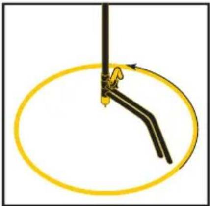
Setting Up the Legs
natural_image
Diagram of a mechanical linkage or tool with a yellow circular motion path and directional arrows (no text or symbols)- Hold the C-stand so the center shaft is resting over your right shoulder, and the feet are pointing down.
- Hold the top leg with your left hand, and rotate the bottom leg with your right hand 1/3 turn counterclockwise until it locks into place.

natural_image
Diagram of a mechanical or electrical component with three curved lines and a central rod, no text or symbols present.- While still holding the top leg in place with your left hand, turn the middle leg 1/3 turn counterclockwise until it locks into place. The bottom leg will rotate with it and lock into place.
- The legs should be spread evenly and locked into place. Place the C-stand down on a flat surface and proceed to mount your lights or accessories.
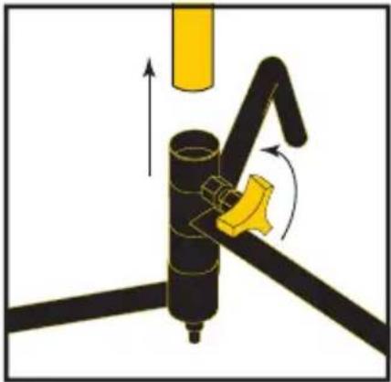
Removing/Replacing the 40 in. Riser
natural_image
Diagram of a mechanical assembly with arrows indicating motion or force direction (no text or symbols)- Remove all fixtures and accessories, and remove the grip arm and grip head.
- Loosen the base locking knob, and lift the 40 in. riser out of the junior receiver.
- Replace it with a 20 in. riser, a junior to baby-pin adapter, or any other 1 18 in. junior diameter adapter.
- Tighten the locking knob until secure.
Sliding Leg C-Stand
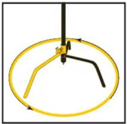
Setting up the Legs

natural_image
Diagram of a mechanical lever mechanism with yellow motion arrows indicating rotation (no text or symbols)Before opening the legs, make sure there are no gaps between the leg collars.
-
Hold the C-stand so the center shaft is resting over your left shoulder, and the feet are pointing down. Loosen the locking knob.
-
Hold the shaft with your left hand, and rotate the top leg with your right hand 1/3 turn counterclockwise until it starts to pull the middle leg with it.
natural_image
Diagram of a mechanical device with a yellow circular frame and black rods, no text or symbols present.-
Continue to turn the top leg counterclockwise. When the top leg stops rotating, the three legs should be spread evenly.
-
Tighten the locking knob until secure.
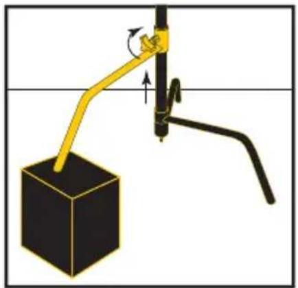
Balancing Using the Sliding Leg
natural_image
Diagram of a mechanical lever system with a black cube and yellow arm, showing motion direction (no text or symbols)The sliding leg adjusts the C-stand's vertical alignment on an uneven surface like a hill, stairs, or curb.
-
Loosen the sliding leg's locking knob.
-
Adjust the height of the sliding leg so the main shaft is vertically aligned, and tighten the locking knob until secure.
Grip Head and Grip Arm
Attaching the Grip Head

natural_image
Diagram of a mechanical device with rotating components and a base component (no text or symbols)Loosen the locking tri-knob counterclockwise and place the grip head's baby receiver over the baby pin. Then tighten the locking handle until secure.
Attaching the Grip Arm
natural_image
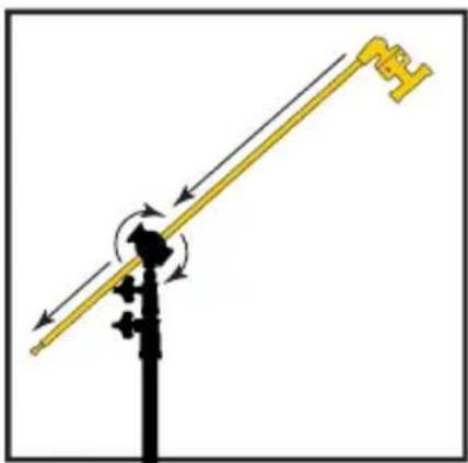
Diagram of a lever system with directional arrows indicating motion (no text or symbols)With the T-handle facing you, loosen the grip head's T-handle, and insert the grip arm into the 5/8 in. hole from the right. Turn T-handle clockwise, and tighten until secure.
Important! Make sure the T-handle faces you, and the load is on the right side of the T-handle. This will prevent the T-handle from accidentally loosening.
C-STAND
| LOAD CAPACITY | 22 lb. (10 kg) |
| MOUNTING OPTIONS | 5/8 in. stud |
| MAXIMUM WORKING HEIGHT | CTB: 118 in. (299.7 cm)CSL: 127 in. (322.4 cm) |
| MINIMUM WORKING HEIGHT | 53.5 in. (136 cm) |
| COLLAPSED HEIGHT | 53.5 in. (136 cm) |
| FOOTPRINT DIAMETER | 37 in. (94 cm) |
| ARM LENGTH | 40 in. (101.6 cm) |
| DETACHABLE BASE | Yes(CTB models only) |
| LEVELING LEG | Yes(CSL models only) |
| FINISH | Matte black, Chrome |
| CONSTRUCTION MATERIAL | Aluminum, Steel |
| WEIGHT | Turtle Base: 12.8 lb. (5.8 kg)Sliding Leg: 12 lb. (5.4 kg) |
GRIP HEAD
| MOUNTING SIZE | 5/8 in. (16 mm) receiver |
| CONSTRUCTION MATERIAL | Aluminum, Steel |
| FINISH | Matte black, Chrome |
| DIAMETER | 2.5 in. (6.3 cm) |
| WEIGHT | 1.6 lb. (0.73 kg) |
GRIP ARM
| LOAD CAPACITY | 22 lb. (10 kg) |
| CONSTRUCTION MATERIAL | Aluminum, Steel |
| FINISH | Matte black, Chrome |
| LENGTH | 40 in (1 m) |
| WIDTH | 2.5 in. (6.3 cm) Grip head |
| WEIGHT | 3.1 lb. (1.4 kg) |
One-Year Limited Warranty
Lowel-Light Manufacturing, Inc. ("Lowel") warrants this product to the original purchaser, under normal use, in accordance with operating instructions, will perform to the specifications published by Lowel at the time of purchase, for a period of one year from the date of purchase by the consumer.
In the event of a defect reported by the consumer within the applicable time period, Lowel will, at its option, replace or repair the defective merchandise at no charge to the consumer for either parts or labor. If the product has been discontinued Lowel reserves the right to replace the product with a model of equivalent quality and function.
Warranty Exclusions
THE WARRANTY SET FORTH ABOVE IS THE ONLY WARRANTY MADE BY LOWEL WITH RESPECT TO THIS LOWEL PRODUCT AND LOWEL DISCLAIMS ALL WARRANTIES OF MERCHANTABILITY AND FITNESS FOR A PARTICULAR PURPOSE AND ANY LIABILITY WITH RESPECT TO SAME WHETHER IN CONTRACT, TORT OR OTHERWISE. IN NO EVENT SHALL LOWEL BE LIABLE FOR LOST PROFITS, OR ANY CONSEQUENTIAL OR INCIDENTAL DAMAGES INCURRED BY THE CONSUMER.
Some states do not allow limitations on how long an implied warranty lasts, and some states do not allow the exclusion or limitation of incidental or consequential damages, so the above limitation may not apply to you.
To obtain warranty coverage, email Tiffen Technical Support at techsupport@tiffen.com or call 1-800-645 2522 to obtain a Return Authorization (RA) number, return the defective product to Tiffen. Please be sure to include the RA number and proof of purchase. Shipment of the defective product is at the purchasers own risk and expense.
For more information email us at info@tiffen.com.
©2019 The Tiffen Company LLC.
All Rights Reserved.
Other product and/or corporate names that are mentioned are property of their respective owners.


Brand : Lowel
Model : CTB-40
Category : Lighting