
01700 - Security alarm Vimar - Free user manual and instructions
Find the device manual for free 01700 Vimar in PDF.


| Type de produit | 24-zone alarm control panel |
| Marque | Vimar |
| Modèle | 01700 |
| Nombre de zones | 24 (expandable via expansion modules) |
| Nombre de zones radio | Up to 32 (with 01729 interface) |
| Nombre de zones filaires intégrées | 6 (default), expandable up to 24 |
| Nombre de sorties | 2 relais (Relay 1, Relay 2) + 24 sorties programmables via modules 01710 |
| Protocole bus | RS485 |
| Alimentation | 230 VAC 50 Hz (via transformateur) |
| Batterie de secours | 12 V (non fournie, à prévoir) |
| Consommation maximale | ~25 W (sans modules externes) |
| Dimensions (L x H x P) | 300 x 250 x 80 mm (approx.) |
| Poids | 1.5 kg (approx.) |
| Température de fonctionnement | -10°C à +50°C |
| Humidité de fonctionnement | 20% à 80% sans condensation |
| Communications | PSTN analogique (intégré), GSM (module 01706 optionnel) |
| Programmation | Via clavier 01705 ou logiciel By-alarm Manager (connexion PC via interface 01725) |
| Mémoire d'événements | 500 événements horodatés |
| Fonctions principales | Armement total (ON), interne (INT), partiel (PAR), zones temporisées, bypass, chime, macro, éclairage trafic, test de zone, etc. |
| Zones programmables | Instant, temporisé, 24h, anti-tamper, macro, etc. (53 types) |
| Sorties programmables | 108 fonctions (ex: alarme, statut zone, éclairage, etc.) |
| Entretien et nettoyage | Utiliser un chiffon sec. Ne pas utiliser de solvants ou produits abrasifs. |
| Sécurité | Anti-sabotage sur centrale et claviers, double ou triple équilibrage, conformité EN-50131 |
| Pièces détachées et réparabilité | Contactez un installateur agréé. Fusibles 3.15A 250V (F3, F4) disponibles. |
| Informations générales | Centrale d'alarme professionnelle, 8 zones virtuelles, 8 utilisateurs, programmateur horaire, commande vocale possible avec module 01713. |
Frequently Asked Questions - 01700 Vimar
User questions about 01700 Vimar
0 question about this device. Answer the ones you know or ask your own.
Ask a new question about this device
Download the instructions for your Security alarm in PDF format for free! Find your manual 01700 - Vimar and take your electronic device back in hand. On this page are published all the documents necessary for the use of your device. 01700 by Vimar.
USER MANUAL 01700 Vimar

natural_image
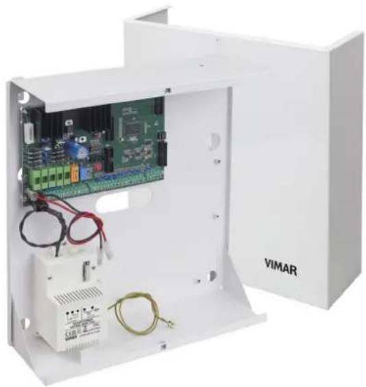
White VIMAR electrical enclosure with internal circuit board and wiring (no visible text or symbols)By-alarm
01700-01700.120
24 zone control panel
Programming manual

natural_image
Solid yellow horizontal bar with no text or symbols
natural_image
Completely blank white image with no visible content, text, or symbols.
natural_image
Blank white image with no visible content, text, or symbols.
natural_image
Blank white image with no visible content, text, or symbols
natural_image
Blank white image with no visible content, text, or symbols
natural_image
Blank white image with no visible content, text, or symbols
natural_image
Blank white image with no visible content, text, or symbols
natural_image
Blank white image with no visible content, text, or symbols
natural_image
Blank white image with no visible content, text, or symbols
natural_image
Blank white image with no visible content, text, or symbols
natural_image
Blank white image with no visible content, text, or symbols
natural_image
Blank white image with no visible content, text, or symbols
natural_image
Blank white image with no visible content, text, or symbols
natural_image
Blank white image with no visible content, text, or symbols
natural_image
Blank white image with no visible content, text, or symbols
natural_image
Blank white image with no visible content, text, or symbols
natural_image
Blank white image with no visible content, text, or symbols
natural_image
Blank white image with no visible content, text, or symbols
natural_image
Blank white image with no visible content, text, or symbols
natural_image
Blank white image with no visible content, text, or symbols
natural_image
Blank white image with no visible content, text, or symbols
natural_image
Blank white image with no visible content, text, or symbols
natural_image
Blank white image with no visible content, text, or symbols
natural_image
Blank white image with no visible content, text, or symbols
natural_image
Blank white image with no visible content, text, or symbols
natural_image
Blank white image with no visible content, text, or symbols
natural_image
Blank white image with no visible content, text, or symbols
natural_image
Blank white image with no visible content, text, or symbols
natural_image
Blank white image with no visible content, text, or symbols
natural_image
Blank white image with no visible content, text, or symbols
natural_image
Blank white image with no visible content, text, or symbols
natural_image
Blank white image with no visible content, text, or symbols
natural_image
Blank white image with no visible content, text, or symbols
natural_image
Blank white image with no visible content, text, or symbols
natural_image
Blank white image with no visible content, text, or symbols
natural_image
Blank white image with no visible content, text, or symbols
natural_image
Blank white image with no visible content, text, or symbols
natural_image
Blank white image with no visible content, text, or symbols
natural_image
Blank white image with no visible content, text, or symbols
natural_image
Blank white image with no visible content, text, or symbols
natural_image
Blank white image with no visible content, text, or symbols
natural_image
Blank white image with no visible content, text, or symbols
natural_image
Blank white image with no visible content, text, or symbols
natural_image
Blank white image with no visible content, text, or symbols
natural_image
Blank white image with no visible content, text, or symbols
natural_image
Blank white image with no visible content, text, or symbols
natural_image
Blank white image with no visible content, text, or symbols
natural_image
Blank white image with no visible content, text, or symbols
natural_image
Blank white image with no visible content, text, or symbols
natural_image
Blank white image with no visible content, text, or symbols.
natural_image
Blank white image with no visible content, text, or symbols.
natural_image
Blank white image with no visible content, text, or symbols.
natural_image
Blank white image with no visible content, text, or symbols.
natural_image
Completely blank white image with no visible content, text, or symbols.
natural_image
Blank white image with no visible content, text, or symbols.
natural_image
Blank white image with no visible content, text, or symbols.
natural_image
Blank white image with no visible content, text, or symbols
natural_image
Blank white image with no visible content, text, or symbols
natural_image
Blank white image with no visible content, text, or symbols

By-alarmBy-alarm
Index
Introduction
General information 5
Section 1 - Programming the control unit using the keypad 01705
Guidelines for programming the control unit using the keypad 8
Primary menus
Primary menu diagram....10
Settings
Keypad activation....11
Input expansion activation 11
Output expansion activation 11
Reader activation 11
Digital telephone 11
GSM dialler 12
Telephone 01706 12
Direct connection to the computer 12
Clock settings
Control unit time and date 13
Input programming
Zone programming 14
Zone type 14
Number of zone unbalancings to cause an alarm.... 15
Duration of switch alarm pulses 15
Zone areas for different installations 15
Area 1 - 8 15
Zones associated to the areas active on arming ON - INT - PAR 16
Keypads associated to the Areas....16
Readers associated to the Areas 17
Zone alarm options 17
Memo zone alarm in events memory 17
Memo zone restore in events memory 18
Buzzer activated by zone alarm 18
Double balance (alarm - tamper)....19
Triple balance (alarm - tamper - masking) 19
Alarm codes for multiple events 19
Zone auxiliary options 19
Buzzer sound for entry time....19
Buzzer sound for exit time 20
Chime function 20
Door Function 20
Ding Dong Function 21
Which zone cannot be bypassed 21
Zone as last exit door 22
Tamper (anti-tamper) function programming 22
Control unit tamper 22
Keypad tamper 23
Input expansion tamper 23
Output expansion tamper 23
Masking function programming 23
Zone test function programming....24
Radio option programming 25
Transmitter programming....26
Output Programming
Relay 1 programming 29
Relay 2 programming 31
Output programming 31
ID Programming
Installer Code programming and functions 35
Codes....35
User Code programming and functions....35
Codes....35
If the code is active 35
Which area it is associated to 36
Arming management 36
If arming in ON - INT - PAR 36
If switching off....36
If blocking the scheduler 36
If enabling overtime 36
Auxiliary options 37
If changing telephone number 37
If changing code....37
If changing date and time 37
If blocking outgoing calls 37
If accessing the control unit events memory 37
If blocking the keypad buzzer 37
If enabling user remote connection with voice call 37
If enabled for user remote connection via MyWeb 37
If enabled for user remote connection with SMS 37
If excluding zones in the control unit 37
If enabling macros 37
Access control system 38
If blocked by scheduler 38
If sending a telephone call....38
If cancelling a panic alert 38
TAG Settings 38
Acquisition - Delete - Check TAG....38
If the TAG is enabled 39
Which reader is associated to the ID 39
Which output is active 40
Which output is active with Emergency Code 40
Code duration in days 40
Time Programming
Entry and exit times of delayed zones 41
Buzzer duration in case of alarm....41
Zone unbalancing acquisition time 41
Warning time for arming from scheduler 41
Warning cancellation timing....41
Control Programming
Arming function programming....42
If the installer ID is active with the control unit on 42
If self-test is active when arming the control unit 42
If forced arming is active 42
If fast arming is active 42
If fast disarming is active 43
If constant area vision is active on the keypad 43
If the shared zone function is active 43
If the tamper exclusion function is active with OFF ZONE 43
Index
Programming functions on power supplies 43
No mains voltage delay 43
Hour, minute and interval of the self-test call.... 43
Day and month of system maintenance indication 43
Text Programming 43
Info Text 43
Zone Texts 44
ID Texts 44
Output Texts 44
Keypad texts 45
Input expansion texts 45
Reader texts 46
Output expansion texts 46
Area Texts 47
Macro Texts 47
Network card address programming 48
TCP IP address....48
Netmask 49
Gateway 49
TCP port 49
LAN code 49
Macro programming....50
Setting the triggering event 50
Setting the type of triggering event.... 50
Setting the stop macro event 50
Setting the stop macro type 5C
If the macro is stopped by the scheduler 52
If the macro must have automatic restart 52
Settable delay in seconds/minutes 53
Memo macro activation in events memory 53
Macro operation programming 53
Operation 1 - 10 command 53
Operation 1 - 10 Options 53
Events memory view 54
Software Version 54
Restoring the control unit programming to default values 54
Access control system....54
If the reader leds must always be on 55
Scheduler
Time band programming 56
Monday - Sunday 56
Operation 1 - 16....56
Hour - Minute 56
Function type 56
Auxiliary options 56
Holiday period programming 57
Holiday period start and end programming....57
Telephone
Phone number programming 58
Numbers 58
Send protocol 58
Customer Code 58
Zone alarm....59
Zone restoring 59
Call not OK attempts 59
Stop call 59
By-alarm
Index
Telephone parameter programming 60
Wait for answer 60
Pause between attempts....60
Vocal message repetition....60
Number of rings on PSTN for connection in Remote connection 60
Number of rings on GSM for connection in Remote connection 60
Skip voice mail settings 60
If the SIM is rechargeable 61
If the number must be recognised 61
Ring Back activation....61
Events to be associated to telephone numbers 61
Tamper alarm....61
Sensor masking alarm 61
Bypassed zone 61
Area Arming - Disarming 61
No mains voltage 62
No battery 62
Low battery 62
Self-test 62
D.G Batch Events 62
User ID Entry 62
Emergency User ID Entry 62
Medical dispatch call 62
Panic dispatch call 62
Fire dispatch call 62
SIM not charged 62
SIM expiring 62
Association to alarm type for each zone 63
Vocal message recording....63
Address message recording for each area 63
Personalised word recording 63
Password programming for interactive connection 65
Section 2 - Programming the control unit with By-Alarm Manager software
Procedure to enable settings with By-alarm Manager 67
System card 70
General information
All control unit functions can be programmed using a computer which has the By-alarm Manager software installed or using one of the keypads connected to the control unit. The control unit has an RS 485 input for connection to the bus on devices such as keypads, input expansion modules, output expansion modules, radio interfaces and readers.
The devices can be connected either to the RS485 bus or in parallel to the same conductors, respecting the codes on the terminals of the control unit and of the devices themselves, namely:
• + with +
- with -
• A with A
• B with B
For 12 Vdc power supply 0.50 ~mm^2 conductors must be used and for the A and B sensors, 0.22 ~mm^2 conductors; the shield must be connected to the negative with regard to the control unit.

- The keypads have a special anti-tampering button which is activated when the container is opened and when the keypad is removed from the wall.
- The bridge on the side of the button closing causes the full exclusion of the keypad protection
Changing the keypad address.
1) Press and release the RESET push button (PB1) on the keypad card on the right-hand side near the microprocessor (see photo below).
2) Press the ENT button for approx. 1 s.
3) The display will show the physical address of the keypad.
4) Press the ENT button to enter the menu.
5) Using the hand, but Paris, select the desired address.
6) Press ESC twice to confirm the address and exit the menu.

natural_image
Close-up of a green printed circuit board with electronic components and a finger pointing to the surface (no readable text or symbols)Section 1
Programming the control unit using the keypad 01705
Guidelines for programming the control unit using the keypad
- With the power off, connect all devices (both those connected to the RS485 bus and those connected directly to the control unit).
- The control unit is supplied pre-set to manage 6 zones as illustrated in chap. 3 of the installation manual.
If settings other than default are required, connect the 3k3 Ω resistors in the inputs for the unused devices in the control unit, and if the siren and relative tamper resistor have not already been connected, connect the 3k3 Ω resistor directly between the T T terminals on the control unit.
N.B. When powering the system, if the resistors are not connected as described, the keypad will emit a tamper alarm and the procedure described in the control unit installation sheet must be followed (enter user ID to silence the alarm and enter installer ID to proceed with the settings).
- Check that the jumpers required to exclude the control unit anti-tamper devices are present.
- Power up the system.
- Assign the relative ID address to each device connected to the RS485 bus (the assigning procedure can be done via the user interface or dip switch, as described in the respective instruction sheets).
As illustrated in the installation manual, the ID assignment must always be sequential, starting with ID=1 for the first device, ID=2 for the second and so on for all devices of the same category connected to the bus; two devices in the same category must always have different IDs (the radio frequency interfaces 01729 and input expansion modules 01709 and 01704 are devices in the same category and must therefore have a different ID while, for example, an input expansion module 01709, a reader 20478-19478-14478 and an output expansion module 01710 may all have the same ID). If there is more than one keypad, select the one to be used for the settings, which will be assigned ID=1; assign to the other keypads respectively ID=2, 3, etc.
- Run the control unit self-learning procedure. This procedure can be done in two different ways (one alternative to the other):
Method 1 (from the control unit)
- Set dip switch 2 to ON and press the reset PB1 push button for at least 1 s.
- Once the control unit relays have completed a rapid switching sequence, place dip switch 2 to OFF and press the PB1 push button again.
The LED status of the device will indicate the correct outcome of the procedure (where present); for example, for radio frequency interface 01729: - LED fixed on = BUS connection problem.
- LED flashing 1 s ON and 1 s OFF = device not programmed.
- LED flashing briefly every second = device programmed.
If the system has one or more radio frequency interfaces 01729 by default these are defined by the control unit as 8-channel interfaces; if you wish to use more than 8 channels you must eliminate the RADIO 8 interface and associate the respective ID to the RADIO 16 menu.
Mode 2 (from keypad)
Enter the Installer ID in the keypad chosen for the settings (default code 123456), and call up the menu SETTINGS - PROG. BUS 1 or 2 and for each device (reader, keypad, etc.) specify how many are installed in the system, also indicating the respective ID.
For example, if there is an input expansion module with ID=1 and a radio frequency interface with ID=2 which has to manage 8 channels, proceed as follows:
- in the screen INP. EXP. 1-4 enter 1 and 2 to declare that the expansion modules on the bus (wired or radio) with ID 1 and 2.
- in the screen RADIO 8 (1-4) enter 2 to declare that the module with ID=2 is a radio frequency interface with 8 inputs.
Note: having received its own ID, the input expansion module 01709 automatically occupies 4 zones in the system however many devices will actually be connected and, in the same way, the radio frequency interface will also occupy 8 or 16 according to what defined in the specific menu. It is very important to remember which zones are occupied by the associated devices as, in the subsequent settings phases, it must be clear which one belongs to every device connected to the input expansion modules or remote control interfaces; this must be compared with the maximum number of free zones available on the control unit in order to avoid associating additional devices which will not trigger any alarm as they are not managed.
- Following the instructions given in the radio frequency device instruction sheet, set the relative parameters (use of auxiliary inputs, radio range, etc.)
- As described in the instructions for interface 01729 and other radio frequency devices, enter the settings paying attention to the fact that a device associated to the management of auxiliary inputs on separate channels will occupy two or three zones: one for the device and one for each auxiliary input. For tidy programming, note the settings considering that the first radio frequency device programmed will occupy the first zone associated to the interface 01729 and which, if its auxiliary input is programmed immediately afterwards, it will be associated to the subsequent alarm zone and so on.
Note: In the default settings, all the information on the reed/pyroelectric parameters and auxiliary inputs are managed on a single channel; with this setting, information on the unbalanced zone will be sent to interface 01729 if one of the inputs on the radio frequency device is "unbalanced".
By appropriately programming detectors 01727 and 01728 it is possible to assign a separate radio channel to each input (programming done on the device); in this case, it is also necessary to correctly associate the radio channels with separate zones to the interface 01729 (for example three radio channels on the detector 01727 are associated to three different zones).
-
Define the behaviour of the various zones in the SETTINGS-INPUTS-ZONE.PROG. menu (value=50 indicates a disabled zone) associating them to the required areas and setting their functions (delays, etc.).
-
Define the Areas.
-
For each Area, define the associated zones belonging to the entry methods ON, INT and PAR.
- Define the behaviour of Relay 1 to which the sirens are connected and that concerning any use of Relay 2.
- Creation of user IDs and definition of the Areas and functions which can be associated to each code.
By default, user 1 is active on Area 1 with basic permissions (user ID 111111); the following procedure is used to create other users:
- enable the user;
- set the numerical code (which must be different from the default code);
- enter the user settings (assignment of permissions, etc.);
-
associate a transponder key to the user if required.
-
Programme the transponder keys and radio frequency remote controls.
-
Associate the Areas and required functions to the transponder key and the remote control push buttons.
Notes:
- Each transponder key can be associated to a single user and therefore the relative permissions correspond to the user permissions. The procedure is as follows: - acquire the tag (then associated to a specific user);
- indicate the settings for the reader on which the tag is enabled in the specific menu.
-
As concerns the remote controls, simply associate the required function and entry area to each button.
-
Associate any keypad alarm signal (buzzer) to the required zones; it is possible to define the zones for which, in the event of an alarm, the keypad gives off an acoustic signal, also setting the duration.
-
In outdoor sirens, set the acoustic signal duration in the event of an alarm (these are armed/disarmed by Relay 1 but in particular situations like a control unit failure or total blackout of the system with flat batteries they can in turn ring for a set time).
-
If present, programme the GSM transmitter/receiver module 01706. In practice the device must be armed, the phone numbers entered, the user permissions correctly paired and all programming required to manage the telephone part in the desired manner completed (SMS or voice).
-
If present, programme the voice synthesis module 01713 and record any vocal messages.
-
Having completed the programming, check the connections on the detectors connected to the control unit inputs, restore the anti-tamper devices via the jumpers, check the siren connections and finally check the balancing on the sirens and devices with any resistors for double or triple balancing.
-
The new "map" of the bus devices can be downloaded to the PC using the By-alarm Manager software; before importing, enable the connection to the PC via the keypad: - select the Settings e menu and press ENT.
-
scroll through the menu as far as PC <-> Control unit and press ENT.
- press CLR to view YES.
- press ESC to exit the menu.
Finally, from the PC, run Connect -> Receive Programming and the programmed bus devices will be viewed in the specific menus.
Note: When programming with the By-alarm Manager software downloaded to the control unit, from the keypad you can view the features of the whole system (devices on the bus, zone settings, association to areas, etc.).
Primary Menu diagram
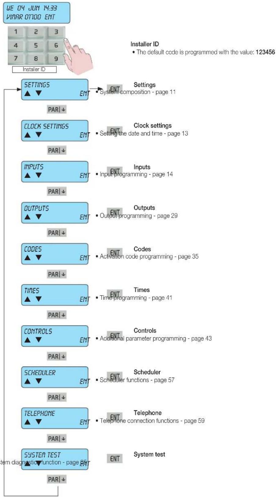
All control unit functions are programmed in 9 primary menus identifying as many function categories.
- The first control unit programming is done via the keypad which is assigned ID=1; therefore, if more than one keypad is installed in the system, the code allowing access to the programming must be entered on the keypad with ID=1.
- The control unit is programmed by entering the Installer code on the keypad; by default this is 123456.
Menu navigation
- Use the navigation buttons ESC, ON, INT and PAR to surf through the Programming Menus:
- The ENT button confirms the data, CLR (clear) cancels it and ESC is used to exit the menu.
flowchart
graph TD
    A["WE 04 JUN 14:33<br>VINAR OT700 ENT"] --> B["INSTALLER ID"]
    B --> C["SETTINGS ▲▼ ENT"]
    C --> D["PART ↓"]
    D --> E["CLOCK SETTINGS ▲▼ ENT"]
    E --> F["PART ↓"]
    F --> G["INPUTS ▲▼ ENT"]
    G --> H["PART ↓"]
    H --> I["OUTPUTS ▲▼ ENT"]
    I --> J["PART ↓"]
    J --> K["CODES ▲▼ ENT"]
    K --> L["PART ↓"]
    L --> M["TIMES ▲▼ ENT"]
    M --> N["PART ↓"]
    N --> O["CONTROLS ▲▼ ENT"]
    O --> P["PART ↓"]
    P --> Q["SCHEDULER ▲▼ ENT"]
    Q --> R["PART ↓"]
    R --> S["TELEPHONE ▲▼ ENT"]
    S --> T["PART ↓"]
    T --> U["SYSTEM TEST ▲▼ ENT"]
    U --> V["PART ↓"]

    C --> W["Settings<br>• System composition - page 11"]
    W --> X["Clock settings<br>• Setting the date and time - page 13"]
    X --> Y["Inputs<br>• Input programming - page 14"]
    Y --> Z["Outputs<br>• Output programming - page 29"]
    Z --> AA["Codes<br>• Activation code programming - page 35"]
    AA --> AB["Times<br>• Time programming - page 41"]
    AB --> AC["Controls<br>• Additional parameter programming - page 43"]
    AC --> AD["Scheduler<br>• Scheduler functions - page 57"]
    AD --> AE["Telephone<br>• Telephone connection functions - page 59"]
    AE --> AF["System test"]

    style A fill:#f9f,stroke:#333
    style B fill:#ccf,stroke:#333
    style C fill:#cfc,stroke:#333
    style D fill:#fcc,stroke:#333
    style E fill:#cff,stroke:#333
    style F fill:#ffc,stroke:#333
    style G fill:#ffc,stroke:#333
    style H fill:#ffc,stroke:#333
    style I fill:#ffc,stroke:#333
    style J fill:#ffc,stroke:#333
    style K fill:#ffc,stroke:#333
    style L fill:#ffc,stroke:#333
    style M fill:#ffc,stroke:#333
    style N fill:#ffc,stroke:#333
    style O fill:#ffc,stroke:#333
    style P fill:#ffc,stroke:#333
    style Q fill:#ffc,stroke:#333
    style R fill:#ffc,stroke:#333
    style S fill:#ffc,stroke:#333
    style T fill:#ffc,stroke:#333
    style U fill:#ffc,stroke:#333
1. Programming the control unit devices

- In SETTINGS you set the composition of the system and the number of installed devices. Having manually assigned the addresses to the devices connected to the RS485 bus, run the self-learning procedure from the control unit and then enter the menu to define the device categories.
- In the SETTINGS menu press ENT to enter the settings.
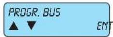
1.1 In BUS PROGRAMMING you can programme all the devices connected to the RS485 bus, specifying for each one the respective ID addresses assigned previously.
PAR↓
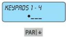
1.1.1 KEYPROS 01705 installed.
- Enter number 1-2-3-4 relative to the installed keypads; the indicator will come on to confirm correct programming. To deselect the keypad repeat the same operation.

1.1.2 Input expansion modules 01709 and radio frequency interfaces 01729 installed. In this menu enter both the IDs of the input expansion modules and those of the radio frequency interfaces (if some of the IDs assigned are not entered the control unit will not detect any alarms signalled by the associated device.
- Press number 1-2-3-4 for the installed devices; the indicator will come on to confirm the correct programming. To deselect the device repeat the same operation.

1.1.3 InDETT.01704 (7-4) defines the input expansions 01704. It is necessary to indicate the ID of any existing input expansions 01704 (each one will occupy 8 alarm zones).
- Press the number 1-2-3-4 for the installed expansions; the indicator will switch on to confirm the pro-programming is correct. To deselect the module the same operation must be performed.
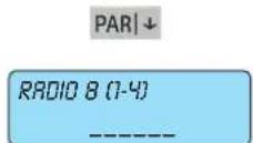
1.1.4 IRADIO 8 (1-4) you define which are the radio frequency interfaces with 8 channels. Indicate the ID of any 8-channel interface present (each one will occupy 8 alarm zones).
- Press number 1-2-3-4 for the installed radio interfaces; the indicator will come on to confirm the correct programming. To deselect the module repeat the same operation.
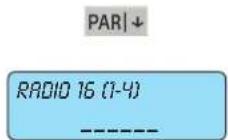
1.1.5 IRADIO 16 [0-4] you define which are the radio frequency interfaces with 16 channels. Indicate the ID of any 16-channel interface present (each one will occupy 16 alarm zones). If there is a 16 channel radio frequency interface no other interfaces or input expansion modules can be set as the maximum number of zones supported by the control unit has been reached.
- Press number 1-2-3-4 for the installed radio interfaces; the indicator will come on to confirm the correct programming. To deselect the module repeat the same operation.
IMPORTANT: The keypad is used to set up to 32 radio frequency channels; of these channels, those exceeding the maximum number set on the radio frequency interface (i.e. more than 8 or 16 depending on the layout) are ignored by the system.

1.1.6 Output expansion modules 01710 installed.
- Press number 1-2-3-4-5-6 for the installed expansions; the indicator will come on to confirm the correct programming. To deselect the module repeat the same operation.
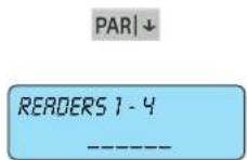
1.1.7 Readers 20478-19478-14478 installed.
- Write the number 1-2-3-4 for the readers installed; the indicator will come on to confirm the correct programming. To deselect the reader repeat the same operation.
- The reader is identified with the address given (see indications given in the control unit or reader installation manual).
ESC|← to go back
As there are no more parameters to be programmed, press ESC|← to return to the previous level of the RS 485 BUS programming menu.
By-alarm
Programming the control unit devices
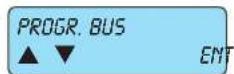
PAR|↓
From the PROGR. BUS menu press the down arrow PAR↓ to access the programming procedures for the other control unit devices.

PAR|↓
1.2 Select YES if the PSTN LINE circuit in the control unit for connecting to the PSTN analogue phone line must be enabled.
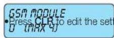
1.3 Select the GSM company interface 01706 to be enabled (set the number of GSM modules present).
- Programme the telephone company of the SIM inserted in the GSM module.
- Write the company number directly, consulting the following table:
| Prog. Function type Phone company | ||
| 0 NO GSM No company selected. | ||
| 1 | TIM TIM mobile phone company. | |
| 2 | VODAFONE | VODAFONE mobile phone company. |
| 3 | WIND | WIND mobile phone company. |

1.4 Select NO if you wish to do the programming from the keypad
settings.
Select YES if you want a direct connection between a PC <-> CONTROL UNIT.
- Press CLR to edit the settings.
- The connection between the PC and the control unit must be done via the interface art. 01725.
- For interactive connection between the control units and the PC install and programme the By-alarm Manager software.
- For the installation and recording procedures, follow the indications given in the By-alarm Manager software manual.
Select NO if you wish to do the programming from the keypad
- Press CLR to edit the settings.
PAR|↓

1.5 Select NO if you do not want the system to comply with the indicated standard.
ESC|←
to go back As there are no more parameters to be programmed, press ESC|← to return to the previous level of the Settings menu.

PAR|↓
From the SETTINGS menu use the down arrow PAR↓ to go to the control unit clock settings menu.
2. Internal clock settings

- In CLOCK SETTINGS you can programme the time and date of the control unit clock. CLOCK SETTINGS menu press ENT to enter the settings.
ENT

PAR|↓
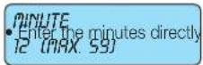
PAR|↓
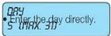
PAR↓

PAR|↓

2.1 Setting the current TIME.
2.2 Setting the current MINUTE.
2.3 Setting the current ORY.
2.4 Setting the current MONTH.
2.5 Setting the current YEAR.
ESC|←
to go back As there are no more parameters to be programmed, press ESC|← to return to the previous level of the Clock Settings menu.
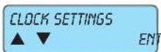
PAR|↓
From the CLOCK SETTINGS menu use the down arrow PAR↓ to view the control unit inputs programming menu.
3. Input programming

ENT

ENT
NUM. ZONE: 1 (MAX 24)
PAR|↓
ZONE TYPE: 0 (MAX 53)
- In INPUTS set all the control unit input parameters.
INPUTS menu press ENT to enter the first zone programming menu.
3.1 From the ZONE PROGRAMMING menu press ENT to enter the programming modes for each zone.
3.1.1 Select the ZONE NUMBER to be programmed.
- Write the number of the zone to be programmed.
3.1.2 Select the TYPE OF ZONE associating it to the operating mode.
- Write the number of the required mode by consulting the table below.
| Progr. Zone type Description | ||
| 0 | Instantaneous | With the control unit on, an alarm is generated as soon as the zone is unbalanced. |
| 1 | Instantaneous with automatic exclusion | If when entering the group the input is unbalanced, the zone is automatically excluded and the event is stored in the events log.It is re-included automatically when the control unit is turned off.Note: if used the IMQ type-approval expires. |
| 2 - 3 | Timed 1 -2 | When the control unit is turned on the exit time 1 - 2 is activated.At the end of this time, a subsequent line unbalancing will enable the re-entry time 1 - 2.At the end of the re-entry time, if the control unit is not turned off an alarm sequence is enabled. |
| 4 | Timed with automatic exclusion/re-inclusion | The zone becomes active after a programmable “exit” time, allowing you to leave having inserted the group; if at the end of this time the zone is unbalanced it is automatically excluded. It will be re-included after the next re-balancing. The zone generates an alarm after a programmable delay calculated from the time in which the entry is unbalanced; during this delay it is possible to disconnect the group without generating alarms.Note: if used the IMQ type-approval expires. |
| 5 | Timed conditioned instantaneous | Instantaneous line which is automatically excluded during the exit and re-entry time of a timed line 1 or 2. |
| 6 24 hours | Line always active, its unbalancing causes an alarm even if the control unit is turned off.Note: to maintain IMQ type-approval: if this mode is used with the anti-theft function, the zones must be associated to all phone numbers. | |
| 7 Anti-Tampering | Additional anti-tampering line; cannot be excluded with "OFF ZONE" operation from keypad and when unbalanced it causes an anti-tampering alarm even when the control unit is turned off. | |
| 8 - 9 - 10 | On ON/INT/PAR | Remote ON line in mode ON, INT, PAR. When unbalanced it causes the control unit to come on in one of the possible modes. |
| 11 - 18 | Suspension Area 1-8 | |
| 19 | Panic reset delayed | If the zone is unbalanced, it cancels the anti-coercion procedure. |
| 20 - 29 | Start macro 1-10 | If the zone is unbalanced, the associated macro is activated. |
| 30 - 39 | Stop macro 1-10 | If the zone is unbalanced, the associated macro is locked. |
| 40 - 49 | Reset Macro 1 - 10 | If the zone is unbalanced, the associated macro is reset. |
| 50 | Not used | |
| 51 | Sensor fault | If the zone is unbalanced a Sensor fault signal is generated (EN-50131). |
| 52 | Anti-theft device fault | If the zone is unbalanced an Anti-theft device fault signal is generated (EN-50131). |
| 53 | Siren fault | If the zone is unbalanced a Siren fault signal is generated (EN-50131). To be used in the input to which the LV output of the siren 01715 is connected. |
The area suspension is an operating mode which can be used to interrupt the scheduler cycle arming and disarming. After the suspension the control unit goes to the state set in the programming for the current time band.
PAR|↓
Important: Panic, theft, tampering events must be associated to at least the first phone number.
This guarantees that in the event of more than one event at the same time panic, theft and tampering are transmitted as a priority.
ZONE UNBALANCING • write the numbe 1 [MAX. 10]
3.1.3 This is the number of ZONE UNBALANCINGS required to trigger the control unit alarm. required unbalancings.
Note: the pulse count only applies to the alarm signal and not to tampering and/or masking that are signalled with the first pulse.
CAUTION: This function cannot be used to connect inert sensors or sensors for roll-up shutters at the inputs from L1 to L8 of the control unit as these detect unbalancings with a time greater than 120 ms and which cannot be calibrated.
PAR|↓
OUR. OF SWITCH ALARM 8 (1=275)
3.1.4 This is the duration of a single unbalancing for it to be considered valid. The acquisition times are shown in the following tables:
| Prog. Description |
| 0 1 ms |
| 1 2 ms |
| 2 5 ms |
| 3 10 ms |
| 4 20 ms |
| Prog. Description |
| 5 40 ms |
| 6 80 ms |
| 7 120 ms |
| 8 160 ms |
| 9 200 ms |
| Prog. Description | |
| 10 600 ms | |
| 11 1 s | |
| 12 2 s | |
| 13 4 s | |
ESC|←
to go back
As there are no more parameters to be programmed, press ESC|← to return to the previous level of the Zone Programming menu.

PAR↓
From the ZONE PROGRAMMING menu use the down arrow PAR↓ to go to the Area Settings menu.

ENT
3.2 In AREAS you programme all the settings for the possible control unit partitions. - From the AREAS menu press ENT to enter the first Zone Programming menu.

PAR↓

PAR|↓

PAR|↓

ENT
3.2.1 Partition Area refers to the possibility to group zones to obtain different systems with a single control unit.
- From the AREA 1 to the AREA 8 menu press ENT to enter the Programming menu for the 8 possible areas.
- The control unit has 8 Areas and for each one must be programmed or associated to the required functions. If you do not need to use more than one area, simply do not associate any function to the areas from 2 to 8.
- The arming methods are used to customise the safety system operation; the control unit 01700 has 3 arming modes which are identified with as many push buttons on the keypad: ON (total arming), INT (internal arming) and PAR (partialised arming). Every area can therefore be independently placed in armed state using one of the 3 different modes at a time.
- If the same zone is associated to 2 or more different areas for the same arming mode, a shared zone is obtained; the shared zone will be active only when all the associated areas are in the ON state; this automation makes programming easier when there are several systems with a shared entrance. Obviously, there may be more than one shared zone.
ENT
ZONES 1-8
(No text)
PAR|↓
ZONES 17 - 24
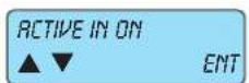
3.2.1.1 In ACTIVE IN ON you programme the zones associated to the arming in ON mode. - Press ENT to enter the settings.
3.2.1.1.1 Select which zone will be ACTIVE IN ON when the Area is armed in ON mode.
• Write the number 1-2-3-4-5-6-7-8 for the zones to be associated.
- The symbol will come on to confirm the association.
- To remove the association write the required number.

flowchart
graph TD
    A["Start"] --> B["To go back"]
    B --> C{Active in ON}
    C --> D["ENT"]
    D --> E["PAR↓"]
    E --> F{Active in INT}
    F --> G["ENT"]
    G --> H{ZONES 1 - 8}
    H --> I["PAR↓"]
    I --> J{ZONES 17 - 24}
    J --> K{ESC← to go back}
    K --> L{Active in INT}
    L --> M{ENT}
    M --> N{Par↓}
    N --> O{Active in PAR}
    O --> P{ENT}
    P --> Q{ZONES 1 - 8}
    Q --> R["PAR↓"]
    R --> S{ZONES 17 - 24}
    S --> T{ESC← to go back}
    T --> U{Active in PAR}
    U --> V{ENT}
    V --> W{PAR↓}
    W --> X{KEYPADS 1 - 4}
    X --> Y{ENT}
    Y --> Z{KEYPADS 1 - 4}
    Z --> AA{PAR↓}
    AA --> AB{KEYPADS 1 - 4}
    AB --> AC{KeyPADS 1 - 4}
    AC --> AD{Par↓}
    AD --> AE{KEYPADS 1 - 4}
    AE --> AF{KeyPADS 1 - 4}

ENT
3.2.1.5 InREADERS 7 - 4 programme the association between the chosen Area and the installed readers.
- Press ENT to enter the settings.
READERS 1-4
3.2.1.5.1 Select which READERS 1 - 4 reader will be associated to the chosen Area.
- Write the number 1-2-3-4 for the reader to be associated.
- The symbol will come on to confirm the association.
• To remove the association write the required number.
ESC|← to go back
As there are no more parameters to be programmed, press ESC|← to return to the reader programming menu level.
READERS 1-4

ESC|← to go back
As there are no more parameters to be programmed, press ESC|← to return to the Area Programming menu level.
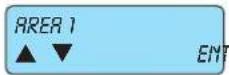
ESC|←
to go back
As there are no more parameters to be programmed, press ESC|← to return to the Area Programming menu level.

PAR↓
From AREA 02 use the down arrow PAR↓ to go to the Alarm Options Settings menu.

ENT
3.3 In ALARM OPTIONS you programme all the function to be associated to the control unit alarm state.
- From the ALARM OPTIONS menu press ENT to enter the settings.

ENT
3.3.1 In MEMO ALARM make the events memory record the alarm.
- Press ENT to enter the settings.

PAR|↓
ZONES 17 - 24
[EMPTY]
ESC|← to go back
3.3.1.1 Select which ZONE 1 - 8 must record the alarm in the control unit events memory.
- Write the number 1-2-3-4-5-6-7-8 for the zones to be associated.
• The symbol will come on to confirm the association.
• To remove the association write the required number.

PAR↓
From MEMO ALARM use the down arrow PAR↓ to view the Reset Memo Menu.

flowchart
graph TD
    A["RESET MEMORY ▲ ▼ ENT"] --> B["ZONES 1 - 8 ----"]
    B --> C["ZONES 17 - 24 ----"]
    C --> D["3.3.2 In RESET MEMO make the events memory record the alarm reset.<br>• Press ENT to enter the settings."]
    D --> E["3.3.2.1 Select which zone must RECORD THE ALARM RESET in the control unit events memory.<br>• Write the number 1-2-3-4-5-6-7-8 for the zones to be associated.<br>• The symbol will come on to confirm the association.<br>• To remove the association write the required number."]
    E --> F["Events Memory: • the control unit has a memory used to record all the fault, arming and disarming events with date and time, the codes entered and alarm and zone reset states, if the function described above is selected in programming; there are 500 recorded events which are automatically updated, deleting the oldest ones.<br>• the events in the memory can be consulted directly by the user and will be shown on the control keypad in the following form:<br>ESC← to go back As there are no more parameters to be programmed, press ESC← to return to the Memo Alarm Reset menu."]
    F --> G["RESET MEMORY ▲ ▼ ENT"]
    G --> H["ZONES 1 - 8 ----"]
    H --> I["ZONES 17 - 24 ----"]
    I --> J["3.3.3 In BUZZER ACTIVE you programme which of the programmed zones will activate the keypad buzzer in the event of an alarm.<br>To set the buzzer length see chap. 6 of this manual.<br>• Press ENT to enter the settings."]
    J --> K["3.3.3.1 Select which zone must ACTIVATE THE BUZZER on the keypad in the event of an alarm.<br>• Write the number 1-2-3-4-5-6-7-8 for the zones to be associated.<br>• The symbol will come on to confirm the association.<br>• To remove the association write the required number."]
    K --> L["ACTIVATE BUZZER ▲ ▼ ENT"]
    L --> M["ZONES 1 - 8 ----"]
    M --> N["ZONES 17 - 24 ----"]
    N --> O["3.3.4 In DOUBLE EOL you programme the zones with double balancing.<br>• Press ENT to enter the settings."]
    O --> P["3.3.4.1 Select which zone must be programmed for DOUBLE BALANCING<br>• Write the number 1-2-3-4-5-6-7-8 for the zones to be associated.<br>• The zones not associated to double balancing will automatically be programmed for single balancing.<br>• The symbol will come on to confirm the association.<br>• To remove the association write the required number."]
    P --> Q["DOUBLE EOL ▲ ▼ ENT"]
    Q --> R["ZONES 1 - 8 ----"]
    R --> S["ZONES 17 - 24 ----"]
    S --> T["ESC← to go back As there are no more parameters to be programmed, press ESC← to return to the Double Balancing menu."]


flowchart
graph TD
    A["ZONES 1 - 8"] --> B["3.4.1.1 Which zone must activate the BUZZER IN on the keypads to indicate the entry time of a timed zone."]
    B --> C["For each zone group, write the number 1-2-3-4-5-6-7-8 for the input lines that must activate the buzzer."]
    C --> D["The symbol will come on to confirm the association."]
    D --> E["To remove the association write the required number."]
    E --> F["The function can be left active for all zones as only the timed zones will make the keypad buzzer ring."]
    F --> G["ZONES 17 - 24"]
    G --> H["ESC← to go back"]
    H --> I["As there are no more parameters to be programmed, press ESC← to return to the Buzzer IN menu."]
    J["BUZZER IN"] --> K["ENT"]
    L["PAR↓"] --> M["From the BUZZER IN menu use the down arrow PAR↓ to view the Buzzer OUT menu."]
    N["BUZZER OUT"] --> O["ENT"]
    P["ENT"] --> Q["3.4.2 In BUZZER OUT you programme which zones programmed with timer must make the keypad buzzer ring."]
    Q --> R["• From the BUZZER OUT menu press ENT to enter the settings."]
    S["ZONES 1 - 8"] --> T["3.4.2.1 Which zone must activate the BUZZER OUT on the keypads to indicate the exit time of a timed zone."]
    U["• The symbol will come on to confirm the association."] --> V["• To remove the association write the required number."]
    W["PART↓"] --> X["• The function can be left active for all zones as only the timed zones will make the keypad buzzer ring."]
    Y["ZONES 17 - 24"] --> Z["ESC← to go back"]
    Z --> AA["As there are no more parameters to be programmed, press ESC← to return to the Buzzer OUT menu."]
    AB["BUZZER OUT"] --> AC["ENT"]
    AD["PAR↓"] --> AE["From the BUZZER OUT menu use the down arrow PAR↓ to go to the Chime menu."]
    AF["The CHIME is a function that makes the keypad buzzer ring when, with the system disarmed, the zone is unbalanced. The sound is continuous and you must enter a User ID to silence it."]
    AG["CHIME"] --> AH["3.4.3 In CHIME you programme which zones will activate the Chime function."]
    AI["ENT"] --> AJ["• From the CHIME menu press ENT to enter the settings."]
    AK["ENT"] --> AL["3.4.3.1 • For each zone group, write the number 1-2-3-4-5-6-7-8 for the input lines that must activate the buzzer."]
    AM["ZONES 1 - 8"] --> AN["3.4.3.1 • For each zone group, write the number 1-2-3-4-5-6-7-8 for the input lines that must activate the buzzer."]
    AO["• The symbol will come on to confirm the association."] --> AP["3.4.3.1 • For each zone group, write the number 1-2-3-4-5-6-7-8 for the input lines that must activate the buzzer."]
    AQ["TO remove the association write the required number."] --> AR["3.4.3.1 • For each zone group, write the number 1-2-3-4-5-6-7-8 for the input lines that must activate the buzzer."]
    AS["PAR↓"] --> AT["• From the CHIME menu press ENT to enter the settings."]
    AU["ZONES 17 - 24"] --> AV["ESC← to go back"]
    AW["ESCI← to go back"] --> AX["As there are no more parameters to be programmed, press ESC← to return to the Chime menu level."]
    AY["CHIME"] --> AZ["ENT"]
    BA["PAR↓"] --> BB["From the CHIME use the down arrow PAR↓ to go to the Door menu."]
    BC["DOOR"] --> BD["3.4.4 In DOOR you programme which zones activate the Chime function."]
    BE["ENT"] --> BF["• From the DOOR menu press ENT to enter the settings."]

flowchart
graph TD
    A["ZONES 1 - 8"] --> B["3.4.4.1 The DOOR is a function that makes the keypad buzzer ring when, with the system disarmed, the zone is unbalanced.<br>The sound is continuous and you must enter a User ID to silence it.<br>For each zone group, write the number 1-2-3-4-5-6-7-8 for the input lines that must activate the buzzer.<br>The symbol will come on to confirm the association.<br>To remove the association write the required number."]
    B --> C["PAR↓"]
    C --> D["ZONES 17 - 24"]
    D --> E["ESC← to go back As there are no more parameters to be programmed, press ESC← to return to the Door menu level."]
    F["DOOR ▲▼ ENT"] --> G["PAR↓ From the DOOR use the down arrow PAR↓ to view the Ding Dong menu."]
    H["DING DOING ▲▼ ENT"] --> I["3.4.5 In DOOR you programme which zones activate the Chime function.<br>• From the DOOR menu press ENT to enter the settings."]
    I --> J["ENT"]
    J --> K["ZONES 1 - 8"] --> L["3.4.5.1 The DING DOING is a function that makes the keypad buzzer ring for two seconds when, with the system disarmed, the zone is unbalanced.<br>The sound will be automatically interrupted even if the zone stays unbalanced.<br>For each zone group, write the number 1-2-3-4-5-6-7-8 for the input lines that must activate the buzzer.<br>• The symbol will come on to confirm the association.<br>• To remove the association write the required number."]
    L --> M["PAR↓"]
    M --> N["ZONES 17 - 24"] --> O["ESC← to go back As there are no more parameters to be programmed, press ESC← to return to the Ding Dong menu."]
    P["DING DOING ▲▼ ENT"] --> Q["PAR↓ From the DING DOING use the down arrow PAR↓ to view the Zone not Bypassable menu."]
    Q --> R["3.4.6 In ZONE NOT BYPASSABLE you programme the zones that cannot be bypassed.<br>• From the ZONE NOT BYPASSABLE menu press ENT to enter the settings."]
    R --> S["ENT"]
    S --> T["ZONES 1 - 8"] --> U["3.4.6.1 By selecting the ZONE NOT BYPASSABLE the zone can never be bypassed, even by the User.<br>• For each zone group, write the number 1-2-3-4-5-6-7-8 for the input lines which cannot be bypassed.<br>• The symbol will come on to confirm the association.<br>• To remove the association write the required number.<br>• The zones programmed in Tamper mode can in any case never be bypassed."]
    T --> V["PAR↓"]
    V --> W["ZONES 17 - 24"] --> X["ESC← to go back As there are no more parameters to be programmed, press ESC← to return to the Zone not Bypassable level."]
    X --> Y["ENT"]
    Y --> Z["PAR↓ From the ZONE NOT BYPASSABLE use the down arrow PAR↓ to view the Zones programmed for pre-alarm menu."]


PAR↓

PAR|↓

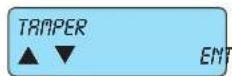
- KEYPRO TAMPER: this is the anti-tamper function protecting the keypad from being opened or pulled off the wall, or having the connecting cables cut.
- INP. EXP. TRIPER is the anti-tamper device coming from the tamper input and input expansion module 01709 communication input.
- OUT. EXP. TAMPER is the anti-tamper device coming from the tamper input and output expansion module 01710 communication input.
ENT
ACTIVATE RELAY 1 YES
PAR|↓
ACTIVATE RELAY 2 YES
PAR↓
ACTIVATE BUZZER YES
PAR|↓
ALARM MEMORY YES
PAR|↓
RESET MEMORY NO
ESC|← to go back
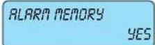
3.5.1 A YES enables ANGIVATION OF RELAY 1 general alarm.
- PressCLR to change the settings.
3.5.2 A YES enables TRETIVATION OF RELAY 2.
- PressCLR to change the settings.
- The use of this condition: RELAY 2 ACTIVE NO annuls the IMQ type-approval.
3.5.3 A YES enables the RETIVATION OF THE KEYPRO buzzer.
- PressCLR to change the settings.
3.5.4 A YES programmes the control unit RECORD THE ALARM in the control unit events memory.
- PressCLR to change the settings.
3.5.5 A YES programmes the control unit RECORD THE ALARM RESET in the control unit events memory.
- PressCLR to change the settings.
As there are no more parameters to be programmed, press ESC|← to return to the Tamper menu level.
PAR↓
From TRAMPER use the down arrow PAR↓ to go to the Masking settings menu.

ENT
3.6 In RASKING the control unit is programmed for detecting a masking state alarm in the sensors (see Triple Balancing).
- From the MASKING menu press ENT to enter the first associated function.

PAR↓

PAR↓

PAR↓
3.6.1 A YES enables the ACTIVATION OF RELAY 1 general alarm.
- Press CLR to change the settings.
3.6.2 A YES enables the ACTIVATION OF RELAY 2.
- Press CLR to change the settings.
3.6.3 A YES enables the ACTIVATION OF THE keypad buzzer.
- Press CLR to change the settings.
ALARM MEMORY YES
3.6.4 A YES programmes the control unit to RECORD THE ALARM in the control unit events memory.
- Press CLR to change the settings.
PAR|↓
RESET MEMORY NO
3.6.5 A YES programmes the control unit to RECORD THE RESET in the control unit events memory.
- Press CLR to change the settings.
PAR|↓
TYPE OF MASKING IN STATE
3.6.6 The type of masking used by the sensor is defined.
- The masking alarm output can be activated in two different ways, depending on the construction characteristics of the sensor; you must therefore consult the sensor manual to identify the operating mode.
- IN STATE : the output is active and remains in this state for the whole time during which the sensor reads the masking; it is reset automatically when the causes of the masking are removed.
- PULSE: the output is active when it reads the sensor masking and after a few seconds it is reset automatically even if the causes persist (pulse function). This is also valid for the sensor anti-masking flashing mode.
ACTIVE ON NO
3.6.7 A YES makes the sensor masking state reading active also from the control unit in armed mode.
ESC|← to go back
As there are no more parameters to be programmed, press ESCI← to return to the Masking menu level.
MASKING ▲ ▼ ENT
PAR↓
From the ARSKING menu use the down arrow PAR↓ to view the Zone Test menu.
ZONE TEST ▲ ▼ ENT
3.7 The ZONE TEST is a function used to control the alarm cycle on certain zones, limiting its functions (see points 3.7.2 to 3.7.5). It is possible to set a time interval in which these zones will not activate the signalling devices in order to monitor whether they are subject to false alarms.
- From the ZONE TEST menu press ENT to enter the first programming menu.
ENT
TEST ZONE ▲ ▼ ENT
3.7.1 In TEST ZONE you programme the zones that will be conditioned by the test functions.
- From the TEST ZONE menu press ENT to enter the first associated function.
ENT
3.7.1.1 For which ZONE FROM 1 TO 8 the test function must be activated.
- For each zone group, write the number 1-2-3-4-5-6-7-8 for the input lines that will be put in test state.
- The symbol will come on to confirm the association.
- To remove the association write the required number.
ESC|← to go back
As there are no more parameters to be programmed, press ESC|← to return to the Test Zone menu level.
TEST ZONE YES
PAR|↓
From the TEST ZONE menu use the down arrow PAR↓ to go to the test function programming menu.
ACTIVATE RELAY 1 YES
3.7.2 Programming a NO, an alarm state caused by the zone to which the test function is associated will not cause the ACTI-VATION OF THE RELAY 1 general alarm.
- PressCLR to change the settings.
PAR|↓
ACTIVATE RELAY 2 YES
PAR|↓
ACTIVATE OUTPUT YES
PAR↓
ACTIVATE BUZZER YES
PAR|↓
TELEPHONE COM. YES
PAR|↓
3.7.3 Programming a NO, an alarm state caused by the zone to which the test function is associated will not cause the RCTI-VATION OF THE RELAY 2. •PressCLR to change the settings.
3.7.4 Programming a NO, an alarm state caused by the zone to which the test function is associated will not cause the RCTI-VATION OF THE OUTPUT/S. - PressCLR to change the settings.
3.7.5 Programming a NO, an alarm state caused by the zone to which the test function is associated will not cause the RCTI-VATION OF THE BUZZER -PressCLR to change the settings.
3.7.6 Programming a NO, an alarm state caused by the zone to which the test function was associated will not activate the PHONE COMMUNICATIONS. - PressCLR to change the settings.
3.7.7 ZONE TEST DURATION you set the test duration in days.
• Write the number of days of the zone test period directly.
- The test period starts from the time you exit the programming.
- After the test period, the zones return to programmed operation, ignoring the test settings.
- Important: - The test settings remain programmed in the control unit, even if the test period has expired, and in fact do not condition the control unit operation in any way.
- If however you enter or exit the programming, even without editing any of the settings, the zone test period will be represented.
- This is to be able to activate the function from Installer Remote Phone Connection; in this way the sensors can be controlled from critical calibration and in difficult environmental positions, putting the device in test mode without having to go directly on site.
- With a value of 0 the zones are constantly being tested and their operation depends on the test configurations.
ESC|← to go back
As there are no more parameters to be programmed, press ESC|← to return to the Zone Test menu level.
ZONE TEST ▲ ▼ ENT
PAR|↓
RADIO OPTIONS ▲ ▼ ENT
ENT
SUPERVISION ▲ ▼ ENT
From the ZOME TEST menu use the down arrow PAR↓ to view the Radio Options menu.
3.8 In RADIO OPTIONS you programme the functions associated to the module 01729.
ENT
ACTIVATE RELAY 1 YES
PAR|↓
ACTIVATE RELAY 2 YES
PAR|↓
ACTIVATE BUZZER YES
PAR|↓
3.8.1 The SUPERVISION is the control the radio receiver has over the receivers; if it does not read a survival signal the programmed functions are activated.
3.8.1.1 A YES enables the ACTIVATION OF RELAY 1 general alarm. - Press CLR to change the settings.
3.8.1.2 A YES enables the ACTIVATION OF RELAY 2. - Press CLR to change the settings.
3.8.1.3 A YES enables the ACTIVATION OF THE keypad buzzer. - Press CLR to change the settings.
By-alarm
Input programming
PAR|↓

ESC|←
to go back
3.8.1.4 A YES programmes the control unit to RECORD THE ALARM in the control unit events memory.
- Press CLR to change the settings.
3.8.1.5 A YES programmes the control unit tRECORD THE ALARM RESET in the control unit events memory.
- Press CLR to change the settings.
As there are no more parameters to be programmed, press ESC|← to return to the Supervision menu.

Fromthe
PAR|↓

SUPERVISION menu use the down arrow PAR↓ to go to the Radio Device Battery management menu.
3.8.2In BATT. LOW RF programmes the functions associated to the radio frequency detector 01727 and 01728 flat battery signal.
ENT
PAR|↓

PAR|↓
PAR|↓
PAR|↓
ESC|←
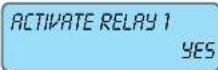
3.8.2.1 A YES enables the ACTIVATION OF RELAY 1 general alarm.
- Press CLR to change the settings.
3.8.2.2 A YES enables the ACTIVATION OF RELAY 2.
- Press CLR to change the settings.
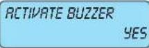
3.8.2.3 A YES enables the ACTIVATION OF THE keypad buzzer.
- Press CLR to change the settings.
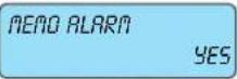
3.8.2.4 A YES programmes the control unit to RECORD THE ALARM in the control unit events memory. This is used to view even the detail of the zone the device belongs to.
- Press CLR to change the settings.
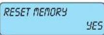
3.8.2.5 A YES programmes the control unit tRECORD THE ALARM RESET in the control unit events memory.
- Press CLR to change the settings.
As there are no more parameters to configure, press ESC|← to return to the radio device battery managing menu.
From the TRANSMITTER BATTERY menu use the down arrow PAR↓ to go to the Transmitters management menu.
PAR|↓

ENT
3.8.3 In TRANSMITTERS you programme the functions associated to the 4 push buttons on the 8 possible Transmitters.

PAR↓
3.8.3.1 For the TRANSMITTERS 1 you programme the function associated to the 4 push buttons on the 8 possible Transmitters.
Enter the number of the transmitter for which you wish to associate the various functions to the respective push buttons (from 1 to 8).

flowchart
graph TD
    A["PUSH BUTTON 1"] --> B["ENT"]
    C["PUSH BUTTON 4"] --> D["ENT"]
    E["PAR"] --> F["↓"]
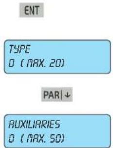
3.8.3.1.1
BUTTON 1, BUTTON 2, BUTTON 3 and BUTTON 4 you have to associate the type of function which must be completed with auxiliary data; having selected the required button (1-4) press ENT to view the options Type and Auxiliaries which have the following functions:
| Progr. | Options | Function description |
| 0 0 | No function | |
| 1 1 - 8 | Area ON mode on [1 - 8] | |
| 2 1 - 8 | Area INTERNAL mode on [1 - 8] | |
| 3 1 - 8 | Area PARTIALISED mode on [1 - 8] | |
| 4 1 - 8 | Area off [1 - 8] | |
| 5 | 1 - 24 | Exclude zone [1 - 24] |
| 6 | 1 - 24 | Re-include zone [1 - 24] |
| 7 | 1 - 24 | Activate output [1 - 24] |
| 8 | 1 - 24 | Deactivate output [1 - 24] |
| 9 | 1 - 20 | Start Macro [1 - 20] |
| 10 | 1 - 20 | Stop Macro [1 - 20] |
| 11 | 1 - 20 | Reset Macro [1 - 20] |
| 12 | 1 - 20 | Enable Macro [1 - 20] |
| 13 | 1 - 20 | Disable Macro [1 - 20] |
| 14 | 1 - 50 | Lock User Codes [1 - 50] |
| 15 | 1 - 50 | Release User Codes [1 - 50] |
| 16 | 1 - 4 | Keypad lock [1 - 4] |
| 17 | 1 - 4 | Keypad Release [1 - 4] |
| 18 | 1-32 | By-me command [1-32] |
| 19 0 - | 255 | Entry of a Delay in minutes or seconds |
ESC|← to go back
As there are no more parameters to be programmed, press ESCI← to return to the Buttons menu level.

Select the other buttons and repeat the procedure illustrated in 3.8.3.1.1.
ESC|← to go back
As there are no more parameters to be programmed, press ESC|← to return to the Transmitters Menu level.

flowchart
graph TD
    A["TRANSMITTERS"] --> B["ESC"]
    B --> C["RADIO OPTIONS"]
    C --> D["▲ ▼"]
    D --> E["ENT"]
PAR↓
ENT

PAR|↓

PAR|↓

PAR|↓

PAR|↓
ESC|←
to go back
3.8.3.1.2 A YES enables the ACTIVATION OF RELAY 1 general alarm.
- PressCLR to change the settings.
3.8.3.1.3 A YES enables the ACTIVATION OF RELAY 2.
- PressCLR to change the settings.
3.8.3.1.4 A YES enables the ACTIVATION OF THE keypad buzzer.
- Press CLR to change the settings.
3.8.3.1.5 A YES programmes the control unit to RECORD THE ALARM in the control unit events memory.
- Press CLR to change the settings.
3.8.3.1.6 A YES programmes the control RECORD THE ALARM RESET in the control unit events memory.
- Press CLR to change the settings.
As there are no more parameters to be programmed, press ESC|← to return to the Transmitter Battery menu.
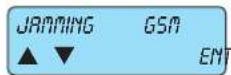
ESC|←
to go back
As there are no more parameters to be programmed, press ESC|← to return the the Transmitter Battery menu.
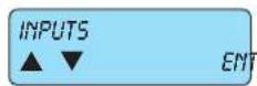
PAR|↓
From the INPUTS menu use the down arrow PAR↓ to view the Output Programming menu.
4. Output Programming

- In OUTPUTS you programme all the control unit output settings.
OUTPUTS menu press ENT to enter the first Output Programming menu.

4.1 RELAY 1 is the positive safety alarm output the sirens must be connected to.
RELAY 1 menu press ENT to enter the first Programming menu.
Output RELAY 1
Positive safety relay, with double exchange, with 1A capacity each. A voltage free exchange is provided
at the output where C is the common, NC is the normally closed exchange and NO is the normally open one; the other one is provided already polarized for connecting the self-powered sirens and the optional non-self-powered internal sirens.
- /+ : power supply for recharging the batteries of the self-powered sirens; the positive is protected by the 3.15A 250V fuse F3.
+S ext : command positive for the self-powered sirens; it constantly provides a positive which fails in the event of an alarm and is protected by the 3.15A 250V fuse F4.
ENT
+S int : power supply positive for the optional non-self-powered sirens; it provides a positive in the event of an alarm and is protected by the 3.15A 250V fuse F4.

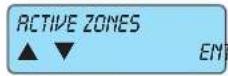
4.1.1 In ACTIVE ZONES you programme the zone to activate relay 1.
- From ACTIVE ZONES press ENT to enter the first Programming menu.
ENT
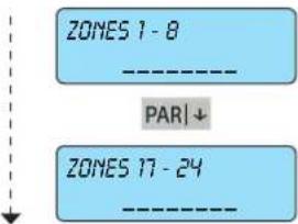
4.1.1.1 Select which ZONE FROM 1 TO 24 must activate the relay in the event of an alarm.
- For each zone group, write the number 1-2-3-4-5-6-7-8 for the zones to be associated
- The default setting associates all the zones to relay 1
• The symbol will come on to confirm the association.
• To remove the association write the required number.
ESC|← to go back
As there are no more parameters to be programmed, press ESC|← to return to the Activated from Zone menu.

From the ACTIVE ZONES menu use the down arrow PAR↓ to go to the other Relay 1 settings.
PAR|↓
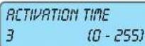
ACTIVATION TIME 3 (0 - 255)
4.1.2 Define what the ACTIVATION TIME of relay 1 must be.
• Write the required time in figures.
- The time base may be in minutes or seconds (see next step).
PAR|↓
TIME MINUTES
4.1.3 The time selected can be in MINUTES or seconds.
- Press CLR to change the settings.
PAR|↓
ARMING DELAY 0 (0 - 255)
4.1.4 Set an RETIVATION DELAY if required.
• Write the required time in figures.
- To maintain IMQ safety system certification the delay on activating the main relay must be programmed to zero
PAR↓
DISARMING DELAY 0 (0 - 255)
4.1.5 Set a DERCTIVATION DELAY if required.
- Write the required time in figures.
ESC|← to go back
As there are no more parameters to be programmed, press ESC|← to return to the Relay 1 Programming menu.
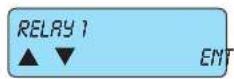
From the Relay 1 Programming
MENU use the down arrow PAR↓ to go to the Relay 2 Programming menu.

ENT
4.2 RELAY 2 is a supplementary alarm output.
- From the Relay 1 men press ENT to enter the first Programming menu.
Output RELAY 2
Non-positive safety relay, with exchange with 1A capacity. The voltage-free exchange is provided at the output where there is the common, NC is the normally closed exchange and NO is the normally open one.

PAR|↓
4.2.1 Use TYPE to select the Relay 2 output function, associating the activation mode.
- Write the number of the required method consulting the output programming table given in point 4.3.2. - Important: make sure that relay 2 is already associated to the tamper.
4.2.2 In R ZONES the relay must activate in the event of an alarm.
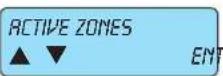
- From ACTIVE ZONES press ENT to enter the first Programming menu.
ENT
ZONES 1-8
[EMPTY]
PAR|↓
ZONES 17 - 24
[EMPTY]
ESC|←
to go back
4.2.2.1 Select which ZONE FROM 1 TO 8 must activate the relay in the event of an alarm.
- For each zone group, write the number 1-2-3-4-5-6-7-8 for the zones to be associated.
• The symbol will come on to confirm the association.
• To remove the association write the required number.
PAR|↓
As there are no more parameters to be programmed, press ESC|← to return to the Activated from Zone menu.
PAR|↓
From the ACTIVE ZONES menu use the down arrow PAR↓ to go to the other Relay 2 settings.

PAR|↓
4.2.3 Define what the ACTIVATION TIME of relay 2 must be.
- Write the required time in figures.
- The time base may be in minutes or seconds (see next step).
PAR|↓
4.2.4 The time selected can be in MINUTES or seconds.
- Press CLR to change the settings.
PAR|↓
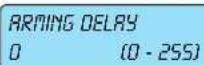
4.2.5 Set an RETIVRATION DELRY if required.
• Write the required time in figures.

ESC|←
4.2.6 Set a DERCTIVATION DELRY, if required.
• Write the required time in figures.
As there are no more parameters to be programmed, press ESC|← to return to the Relay 2 Programming menu level.

From the
PAR|↓
RELAY 2 PROGRAMMING menu use the down arrow PAR↓ to go to the Output Programming menu.

4.3 The active outputs are additional outputs available via the output expansion modules 01710.
ENT

PAR|↓
OUTPUT FUNCTION 0 (MAX 108)
PAR|↓
4.3.1 Choose the NUMBER OF THE OUTPUT to be programmed.
- Write the number of the output to be programmed.
4.3.2 Choose the output function associating the mode.
- Write the number of the required mode by consulting the table on the following page.
| Progr. Type of function Description | ||
| 0 No function | No associated function. | |
| 1 | Zone state(circuit test) | When one of the associated zones is unbalanced the output is activated, while if a zone is excluded the exit is activated intermittently; the output does not follow the programmed times. |
| 2 | Zone state(not flashing) | When one of the associated zones is unbalanced the output is activated; the output does not follow the programmed times. |
| 3 Timed | zone state | The output is activated when one of the associated zones is unbalanced; the output is deactivated at the end of the programmed time (classic application: stair lights).Note: the programmed time starts from when the zone is re-balanced. |
| 4 Zone | alarm | The output is activated when one of the associated zones sets off an alarm, following the programmed time.Time:T1 |
| 5 Anti-tampering zone | The output is activated when one of the associated zones sets off an anti-tampering alarm, following the programmed time.Time:T1 | |
| 6 Masking | The output is activated when one of the associated zones sets off a masking alarm, following the programmed time.Time:T1 | |
| 7 General anti-tampering | The output is activated when any anti-tampering alarm is triggered from any part, following the programmed time.Time:T1 | |
| 8 | Control unit anti-tampering | The output is activated when there is a anti-tampering alarm on the control unit, following the programmed time.Time:T1 |
| 9 Keypad anti-tampering | The output is activated when there is a anti-tampering alarm on one or more keypads, following the programmed time.Time:T1 | |
| 10 | Input expansion Tamper | The output is activated when there is a anti-tampering alarm on one or more input expansion modules 01709, following the programmed time.Time:T1 |
| 11 | Output expansionTamper | The output is activated when there is a anti-tampering alarm on one or more output expansion modules 01710, following the programmed time.Time:T1 |
| 12 - 19 | Area on 1-8 | The output is activated when the selected group is inserted in one of the three modes. If during the last on period there was an alarm and the output activation duration is not zero, when disconnecting the group the output flashes until reconnection, or otherwise is deactivated. |
| 20 - 27 | Area ON on 1-8 | It is activated when the selected group is on in ON mode.Time:T4 |
| 28 - 35 | Area INT on 1-8 | As above, when the selected group is on in INT mode.Time:T4 |
| 36 - 43 | Area PAR on 1-8 | As above, when the selected group is on in PAR mode.Time:T4 |
| 44 | Activation from keypadRFA, PO | The outputs programmed in this mode can be activated from a user code, a remote phone using the RFA function and from a programmable time switch. If the activation duration is 255 the output function is toggle otherwise it follows the programmed time. |
| 45 No mains | It is activated when there is no 230 V mains voltage to the control unit.Time: T2 | |
| 46 Battery trouble | It is activated when the control unit or additional power supply battery level is low or not available.Time: T2 | |
| 47 Cut telephone line It is activated | when the phone line is cut.Time: T2 | |
| 48 Failed GSM signal It is activated | when there is no GSM signal on the module 01706.Time: T2 | |
| 49 | Sim used up | It is activated when the SIM CARD inserted has less than 5 EUR.Time: T2. |
| 50 On line PSTN dialler It is activated | when the phone communicator occupies the line.Time: T2 | |
| 51 On line GSM | It is activated when the module 01706 is on line.The output follows the set times.Time: T2 | |
| 52 | Self-test (battery) | It is activated when the control unit runs the dynamic battery test.Time: T3 |
| 53 | NoPC connection | It is activated when there is no direct connection with the PC.Time: T3 |
| 54 Incorrect code | It is activated when an incorrect code is entered three times in a row both from the keypad and from an RFA telephone connection.Time: T3 | |
| 55 Chime | It is activated when the lines associated to the chime function are unbalanced.This output is reset when a valid user code is entered for the group the relative zones belong to; the output does not follow the programmed time. | |
| 56 Ding dong | It is activated when the lines associated to the Din Don function are unbalanced.Time: T3 | |
| 57 | Advanced warning turning on by Prog. Timer | It is activated during the programmable time switch on notification time.Time: T3 |
| 58 Installer ID | It is activated when an installer code is entered and is deactivated when you exit programming regardless of the programmed time value. | |
| 59-66 Area 1-8 | The exit is activated when the re-entry time for the corresponding group is progress and is deactivated after the time or if the group is turned off. | |
| 67-74 Area 1-8 | The exit is activated when the exit time for the corresponding group is progress and is deactivated after the time or if the group is turned off. | |
| 75 Output AND Zone | The output is activated when all the associated entry lines cause an alarm.Time: T3 | |
| 78 | Remote function access active | The output is active when an RFA remote function session is in progress.Time: T1 |
| 79 | Key (TAG) recognised | The output is activated when a proximity key is recognised.Time: T1 |
| 80 | General output (RFA-TAST-PO) | The output is activated when commanded from a user code, emergency code, programmable time switch, macro or RFA.Time: T3 |
| 81 Panic message | The output is activated when a panic call is made from the keypad (ON + 4).Time: T3 | |
| 82 Doctor Message | The output is activated when a doctor call is made from the keypad (ON + 5).Time: T3 | |
| 83 Fire Message | The output is activated when a fire call is made from the keypad (ON + 6).Time: T3 | |
| 84 Public holiday | The output is active when there is a public holiday running on the programmable time switch.Time: T2 | |
| 85 | Locked Prog. Timer (PO) | The output is activated when the programmable time switch is disabled by the user.Time: T2 |
| 86 Non-routine | The output is active when overtime is running on the programmable time switch.Time: T2 | |
| 87 Keypad lock The output is active when the associated keypad is locked.Time: T2 | ||
| 88 - 95 | Suspension Area 1-8 | The output is active when the corresponding group is suspended.Time: T2 |
| 96 User codes blocked | The output is active when one or more associated codes are locked (by the Programmable time switch or an appropriately programmed input).Time: T2 | |
| 97 Pre-alarm | The output is activated at the end of the pre-alarm time if the coercion condition is not re-set.Time: T3 | |
| 98 Phone line ring-tone | The output is activated when the telephone connected to the network rings.Time: T3 | |
| 99 GSM | line ring-tone | The output is active when the GSM module 01706 is receiving a call.Time:T3 |
| 100 Incoming SMS | The output is activated when a text message arrives through the GSM module 01706.Time:T3 | |
| 101 AND Outputs | The output is activated when all the associated outputs cause an alarm.Time:T3 | |
| 102 OR Outputs | The output is activated when one of the associated outputs causes an alarm.Time:T3 | |
| 103 Gate | The output is activated when one of the associated entrances is activated from a transponder key.Time:T1 | |
| 104 | Caller recognition (via GSM) | The output is activated when the associated numbers are recognised on arrival by the GSM module 01706.Time:T1 |
| 105 SIM | expiring | The output is activated when there are 30 days left until the SIM expires.Time:T1. |
| 106 Fail supervision | ||
| 107 Radio battery trouble | ||
| 108 Janiming | ||
For the usable and therefore programmable time values, comply with what stated in the table below.
| Times Times | |
| T 1 | 0 : armed for 3 seconds |
| 1 .. 253 : armed for the programmed seconds or minutes | |
| 254 : armed until the area to which the zone is associated is disconnected | |
| 255 : follows the zone alarm status (disarmed if the zone returns from the alarm status) | |
| T2 | If the activation length is 255 the output follows the signalling status otherwise it follows the programmed time |
| T3 The output on duration follows the programmed time | |
| T4 | 0 : a pulse is given on arming and again on disarming. |
| 1 .. 253 : armed for the programmed seconds or minutes | |
| 255 : follows the signalling status | |
ACTIVATION TIME
0 (0-255)
ase may be
4.3.3 Define the ACTIVATION TIME of the active output selected.
• Write the required time in figures.
In minutes or seconds (see next step).
PAR↓
TIME SECONDS
4.3.4 The selected time can be in SECONDS or minutes.
- Press CLR to change the settings.
PAR↓
ARMING DELAY 0 (0 - 255)
4.3.5 Set an ACTIVRATION DELAY if required.
• Write the required time in figures.
PAR↓
DISARMING DELAY 0 (0 - 255)
4.3.6 Set a DERCTIVATION DELRY if required.
• Write the required time in figures.
PAR↓
OUT. MODE 1 NORM.DISARMED
4.3.7 In OUTPUT MODE you programme the output state:
• Write the required time in figures.
Not active: normally does not supply any voltage; a negative is supplied when the programmed condition occurs.
Active: constantly supplies a negative which is stopped when the programmed condition occurs.
PAR↓
MEMO ARMING
NO
PAR↓
ACTIVE ZONES
EN
4.3.8 IMENO ACTIVATION with a YES you programme any active output state change is recorded in the control unit events memory.
- PressCLR to change the settings.
ENT
ZONES 1-8
(No text)
PAR|↓
ZONES 17 - 24
(No text)
ESC|←
to go back
n ACTIVE ZONES you programme the zone which must activate the output.
ACTIVE ZONES Express ENT to enter the first Programming menu.
ACTIVE ZONES

ENT
ESC|←
to go back
1.1 Select which ZONE FROM 1 TO 8 must be activated in the event of unbalancing of the active output selected.
- For each zone group, write the number 1-2-3-4-5-6 for the zones to be associated.
• The symbol will come on to confirm the association.
• To remove the association write the required number.
As there are no more parameters to be programmed, press ESC|← to return to the zone activation menu level.
VE OUTPUTS

ENT
ESC|←
to go back
As there are no more parameters to be programmed, press ESC|← to return to the Output Programming menu level.
As there are no more parameters to be programmed, press ESC|← to return to the Output Programming menu level.

PAR|↓
From the OUTPUTS menu use the down arrow PAR↓ to return to the Code Programming menu level.
5. ID Programming

- The Codes are used to manage all the control unit functions and are authentic access keys.
- The first 15 default codes are given in the following table and by default programming only the Installer ID and the User 1 ID are enabled; all other User IDs must be activated via the programming.
| Installer User 1 | User 2 User 3 User 4 | User 5 | |||
| 1 1 1 1 1 1 2 2 2 | 2 2 2 3 3 3 3 3 3 4 4 | 4 4 4 4 5 5 5 5 5 5 | |||
| User 6 User 7 | User 8 User 9 User 10 | ||||
| 1 2 3 4 5 6 6 6 6 | 6 6 6 7 7 7 7 7 7 8 8 | 8 8 8 8 9 9 9 9 9 9 0 0 | 0 0 0 0 | ||
| User 11 User 12 | User 13 User 14 User 15 | ||||
| 1 0 0 0 0 0 1 0 0 | 1 0 0 1 0 0 2 0 0 1 0 | 0 3 0 0 1 0 0 4 0 0 |
Press ENGNT to enter the settings.

ENT

5.1 INSTALLER 10 you programme the figures comprising the code.
- From the INSTALLER ID menu press ENT to enter the settings.
ESC|← to go back As there are no more parameters to be programmed, press ESC|← to return to the Installer ID Programming menu level.

PAR|↓
From the Installer ID PROGRAMMING MENU use the down arrow PAR↓ to go to the User ID Programming menu.
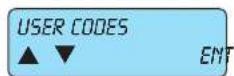
5.2 InUSER IDS you enter the figures comprising the ID.
- Press ENT to enter the programming.
ENT

PAR|↓

ENT
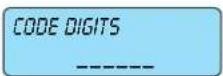
ESC|←
to go back
Select the NUMBER OF THE CODE you wish to programme.
- Write the number of the code you wish to programme.
- With the down arrow PAR↓ go to the User ID parameter settings.
5.2.2 In CODE DIGITS you programme the digits comprising the code.
- From the CODE DIGITS menu press ENT to enter the settings.
5.2.2.1 You enter the value of the chosen code.
- Press CLR to delete the current code.
- Write the new code.
- Press ENT to confirm the new code.
As there are no more parameters to be programmed, press ESC|← to return to the Code Digits Programming menu level.
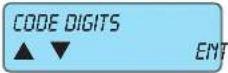
From the Code Digits Programming
MENU use the down arrow PAR↓ to go to the Code properties programming menu.

PAR↓
5.2.3 A YES programmes the ACTIVE CODE.
- Press CLR to change the settings.

ENT
5.2.4 InACTIVE AREAS you associate the code to the control unit area.
ACTIVE ARESromethepress ENT to enter the settings.
AR.12345678
5.2.4.1 Select anARER 12345678 to associate the Code to.
• Write the number 1-2-3-4-5-6-7-8 for the areas it is associated to.
• The symbol will come on to confirm the association.
• To remove the association write the required number.
ESC|←
to go back
As there are no more parameters to be programmed, press ESCI← to return to the Active Areas menu level.

PAR|↓
From ACTIVE AREAS use the down arrow PAR↓ to go to the Arming and Scheduler Settings menu.

ENT
5.2.5 In the ARMING/SCHEDULER menu you programme all the functions for the arming states.
- PressENT to enter the settings.

PAR|↓
5.2.5.1 A YES enables the Code or ARMING ON .
- PressCLR to change the settings.

PAR|↓
5.2.5.2 A YES enables ARMING INTERNAL.
- Press CLR to change the settings.

PAR|↓
5.2.5.3 A YES enables ARMING PARTIALISED
- Press CLR to change the settings.
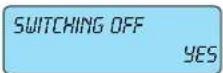
PAR|↓
5.2.5.4 A YES enables the Code to DISARM the control unit.
- Press CLR to change the settings.

PAR|↓
5.2.5.5 A YES enables the Code to BLOCK THE SCHEDULER.
- Press CLR to change the settings.

ESC|←
5.2.5.6 A YES enables the Code to ENABLE OVERTIME.
- Press CLR to change the settings.
As there are no more parameters to be programmed, press ESC|← to return to the Arming Programming menu.
ARMING / SCHEDULER ▲ ▼ EMT
Fromthe
PAR|↓
AUXILIARY OPTIONS ▲ ▼ ENT
ARMING programming menu use the down arrow PAR↓ to go to the Auxiliary Options programming menu.
5.2.6 In the AUXILIARY OPTIONS you can programme additional User ID properties.
- Press ENT to enter the settings.
ENT
CHANGE TELEPH. YES
PAR|↓
CHANGE CODE YES
PAR|↓
CHANGE OTHER CODES YES
PAR|↓
CHANGE DATE YES
PAR|↓
ABORT CALLS NO
PAR|↓
VIEW MEMORY YES
PAR|↓
BLOCK BUZZER YES
PAR↓
REMOTE VOCAL MANAGEMENT NO
PAR|↓
REMOTE SMS MANAGEMENT NO
PAR|↓
OFF ZONE ACTIVE YES
PAR|↓
ACT. MACRO YES
ESC|←
to go back
5.2.6.1 A YES enables the User ID to be able to CHANGE THE TELEPHONE NUMBERS. •PressCLR to change the settings.
5.2.6.2 A YES enables the User ID to be able to EDIT ITS OWN CODE - Press CLR to change the settings.
5.2.6.3 A YES enables the User ID to be able to EDIT OTHER CODES - Press CLR to change the settings.
5.2.6.4 A YES enables the User ID to be able to CHANGE THE DATE. - Press CLR to change the settings.
5.2.6.5 A YES enables the User ID to be able to suspend calls in the event of an alarm. - Press CLR to change the settings.
5.2.6.6 A YES enables the User ID to VIEW THE EVENTS MEMORY of the control unit. - PressCLR to change the settings.
5.2.6.7 A YES enables the User ID to BLOCK THE BUZZER on the keypad. - Press CLR to change the settings.
5.2.6.8 With REMOTE VOCAL MANAGEMENT YES enables the User ID to remotely connect the voice user. - Press CLR to change the settings.
5.2.6.9 With REMOTE SMS MANAGEMENT YES enables the User ID for remote connection via SMS. - Press CLR to change the settings.
5.2.6.10 With OFF ZONE ACTIVE YES enables the User ID to bypass zones. - Press CLR to change the settings.
5.2.6.11 With ACTIVATE MACRO YES, the User ID is enabled to activate the macro-instructions. - Press CLR to change the settings.
As there are no more parameters to be programmed, press ESC|← to return to the Auxiliary Options menu level.
Fromthe

PAR|↓
AUXILIARY OPTIONS programming menu use the down arrow PAR↓ to go to the Access Control Settings menu

ENT
5.2.7 ACCESS CONTROL you programme some special functions of the Code.
- Press ENT to enter the settings.

PAR|↓
5.2.7.1 A YES allows the code to BLOCK THE SCHEDULER.
- PressCLR to change the settings.
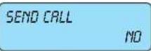
PAR|↓
5.2.7.2 A YES allows the code to trigger a PHONE CALL send.
- PressCLR to change the settings.

ESC|←
5.2.7.3 With RESET PAINIC in YES, the code can block a silent alarm phone call.
- Press CLR to change the settings.
As there are no more parameters to be programmed, press ESC|← to return to the Access Control menu level.
From
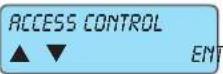
PAR|↓
ACCESS CONTROL use the down arrow PAR↓ to go to the proximity key (TAG) Settings menu, associating it to the User ID.

ENT
3 ITAG SETTINGSyou programme the proximity key for the User ID.
TRG SETTINGS from the press ENT to enter the settings.
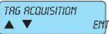
ENT
5.2.8.1 In TRG ACQUISITION you associate a proximity key to the User ID.
- PressENT to enter the settings.

ENT
ENT

ESC|←
to go back
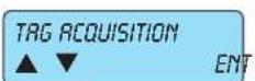
ENT

In TAG ACQUISITION you associate a proximity key to the User ID.
- PressENT to enter the settings.
PAR|↓From
GENERAL KEY use the down arrow PAR↓ to go to the menu associating the key to the entry function.

ENT
ESC|←
to go back

From TAG ACQUISITION use the down arrow PAR↓ to go to the Cancel TAG menu.
PAR|↓

ENT

ENT
ESC|←
In CANCEL TAG you remove the association of a proximity key to the User ID.
- PressENT to enter the settings.
5.2.8.2.1 I6GENERAL KEY you associate a proximity key to the system arming and disarming function.
- PressENT to enter the settings.
5.2.8.2.1.1 Confirm with ENT the request ARE YOU SUREP the tag will be cancelled and confirmed on the display.
- Press ENT to confirm the cancellation, CLR to deletion the operation.
Press ESC|← to exit the acquisition and return to the previous menu.

PAR|↓
From GENERAL KEY use the down arrow PAR↓ to go to the menu associating the key to the entry function.
ENT

ESC|←
to go back Press ESC|← to exit the acquisition and return to the previous menu.

ESC|←
to go back
5.2.8.3.1.1 Confirm with ENT the request ARE YOU SUREP the tag will be cancelled and confirmed on the display.
- Press ENT to confirm the cancellation, CLR to deletion the operation.
As there are no more parameters to be programmed, press ESC← to return to the TAG Acquisition menu level.

m the CANCEL TAG menu use the down arrow PAR↓ to go to the TAG Enabling menu.
PAR|↓

PAR|↓
5.2.8.4 A YES in the ENABLED menu means that the proximity key associated to the code is active.
- PressCLR to change the settings.
By-alarm
ID Programming
READER 1 - 4
5.2.8.5 In READER 1 - 4 you associate the readers to the transponder key to the User ID.
- Write the number 1-2-3-4 for the readers installed; the indicator will come on to confirm the correct programming. To deselect the reader repeat the same - The reader is identified with the address given (see indications given in the control unit or reader installation manual).

to go back
As there are no more parameters to be programmed, press ESC|← to return to the previous level of the TAG settings menu

From
PAR|↓
TAG SETTINGS use the down arrow PAR↓ to go to Programming other functions.

PAR|↓

PAR|↓
5.2.9 With aYES, you ACTIVATE THE PROGRAMMED OUTPUT whenever the User ID is entered on the keypad.
- Write the number corresponding to the output to be associated.
5.2.10 A YES, ACTIVATES THE EMERGENCY OUTPUT whenever the Emergency Code is entered on the keypad.
- Write the number corresponding to the output to be associated. - The Emergency ID is the code originating from the User ID to which a unit is added. - It is used to manage all the control unit functions, such as User ID it originates from, and in addition can activate silent calls and, where programmed, also the secondary relay.

ESC|←
5.2.11 Programme the days of the CODE DURATION, after the programmed time, the code will no longer be active.
- Enter the total number of days in which the User ID will be active. - Entering 0 means an unlimited duration, so the code will always be active.
As there is no programming for the selected code, press ESC← to return to the Code 1 number menu.

ESC|←
to go back
5.3 By selecting number 2, you select User ID 2 and scrolling through the programming seen above for Code 1 (starting from point 5.2.2) all the parameters are programmed.
Having finished programming all the required user IDs, press ESCI← to exit the single user ID programming and return to the previous User IDs menu.

ESC|←
to go back
As there are no more parameters to be programmed, press ESC|← to return to the ID settings menu

PAR|↓
From the IOS menu use the down arrow PAR↓ to go to the Time Programming menu.
6. Time Programming
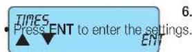
- In the Time programming all the control unit times are programmed.
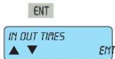
ENT
ENTRY TIME 1 30 (0 - 255 SEC)
PAR|↓
OUTPUT TIME 30 (0 - 255 SEC)
PAR|↓
ENTRY TIME 2 45 (0 - 255 SECO)
PAR↓
OUTPUT 2 TIME 45 (0 - 255 SEC)
PAR↓
ENTRY TIME 3 60 (0 - 255 SEC)
PAR|↓
OUTPUT 3 TIME 60 (0 - 255 SEC)
ESC|← to go back

PAR↓
BUZZER DURATION 2 (0 - 255 MIN)
PAR|↓
SCHEDULER WARNING 30 (0 - 255 MIN)
PAR|↓
PRE-ALARM 0 (0 - 255 MIN)
ESC|← to go back

PAR|↓
6.1 InTIMES IN OUT you programme the entry and exit times of the timed lines.
- Press ENT to enter the settings.
6.1.1 InENTRY TIME 7 you programme the entry time on the timed line 1.
- Enter the seconds directly.
6.1.2 InEXIT TIME 1 you programme the entry time on the timed line 1.
- Enter the seconds directly.
6.1.3 InENTRY TIME 2 you programme the entry time on the timed line 2.
- Enter the seconds directly.
6.1.4 IrEXIT TIME 2 you programme the entry time on the timed line 2.
- Enter the seconds directly.
6.1.5 InENTRY TIME 3 you programme the entry time on the timed line 3.
- Enter the seconds directly.
6.1.6 InEXIT TIME 3 you programme the entry time on the timed line 3.
- Enter the seconds directly.
As there are no more parameters to be programmed, press ESCI← to return to the entry and exit time programming menu level.
From TIMES IN - OUT use the down arrow PAR↓ to go to the Programming menu for the keypad buzzer duration.
6.2 InBUZZER DURATION you programme the time the keypad buzzer rings for in the event of an alarm (if it has already been activated as described in chap. 3 of this manual).
- Enter the minutes directly.
6.3 InSCHEDULER WARNING you programme the warning time in which the keypad buzzer will warn that the auto arming is in progress from the scheduler.
- Enter the warning minutes directly.
- During the warning time it is possible to enter the overtime, which will shift the arming by one hour.
- Overtime can be armed not more than three times, after which the auto arming from the scheduler will in any case be run.
- The overtime can be entered if the User ID running the operation has been enabled (see point 5.2.4.6).
6.4 InPRE-ALARM you programme the delay time that allows the User to block the silent panic call, unbalancing a zone programmed with Delayed Panic Reset (see: type 19).
- Enter the warning minutes directly.
As there are no more parameters to be programmed, press ESC|← to return to the time settings menu
From the TIMES menu use the down arrow PAR↓ to view the Controls Programming menu.
7. Control Programming

- In the CONTROLS programming you can set all the control unit controls.
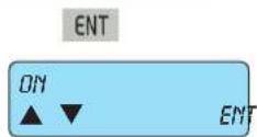
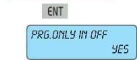

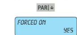
- The use of the condition: PAR↓

7.1 In the ARMING menu you programme the control unit functions associated to the arming.
- Press ENT to enter the settings.
7.1.1 A YES in the PROGRAMMING ONLY IN OFFallows access to the control unit programming only when this is in the disarmed state, using the Installer ID.
- Press CLR to change the settings.
7.1.2 A YES in the SELFTEST ON ARMING activates the power control function each time the control unit is armed.
- PressCLR to change the settings.
7.1.3 A YES FORCED ARMING allows the user, via the User ID, to arm the control unit even when the input lines are unbalanced or open.
- Press CLR to change the settings.
NO FORCED ARMINGannuls the IMQ type-approval.
7.1.4 A YES inFAST ARMING allows the user to arm the control unit in fast mode, simply by pressing ON or INT or PAR three times.
- Press CLR to change the settings.
- A NO means that to arm the control unit the following operations must be performed:
1) Enter the User ID.
PAR↓
2) Press ON or INT or PAR to select the required arming mode.
3) Press ENT to confirm your choice.

7.1.5 A YES inFRST DISARMING allows the control unit to be disarmed in fast mode, simply by entering the User ID.
- Press CLR to change the settings.
the control unit the following operations must be performed:
1) Enter the User ID.
PAR|↓
2) Press 0 / OFF to disarm the control unit.
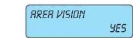
7.1.6 A YES inVIEW ARES ensures the permanent display of the Area states on the keypad.
- Press CLR to change the settings.

7.1.7 A YES iARES IN OR? means that, if the same zone has been associated to more than one area, it is considered shared (see point 3.2.1); NO means that the Areas manage the zones independently in the various arming modes.
- PressCLR to change the settings.
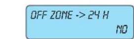
ESC|← to go back
As there are no more parameters to be programmed, press ESC|← to return to the Arming menu level.

PAR↓
From ARMING use the down arrow PAR↓ to go to the Power supply Programming menu.

7.2 In the POWER SUPPLY menu you programme the control unit functions associated to the power supply.
- Press ENT to enter the settings.
ENT
MAINS FREQUENCY 50 Hz
PAR|↓
RET. NO MAINS 0 (0 - 255 MIN)
7.2.1 InAINS FAULT DELAY you programme after how many minutes the control unit must signal that there is no mains voltage by phone communicator.
- Enter the phone communication delay time directly in minutes.
- Enter 0 to disable the function, so the communication will be sent immediately.
PAR|↓
SELF-TEST TIME 0 (MAX. 23)
PAR|↓
7.2.2 IrSELF-TEST TIME you programme the time at which the control unit must run the Self-test.
- Enter the time directly.
- The Selftest is a periodic function that checks that the batteries powering the control unit and other supplementary power supplies are charging correctly.
SELF-TEST MINUTE 0 (MAX. 59)
PAR|↓
7.2.3 IrSELF-TEST MINUTE you programme the minute in which the control unit must run the Selftest.
- Enter the minutes directly.
SELF-TEST INTERVAL. 0 (0.255 HOURS) - Enter 0 to not enable
PAR↓
7.2.4 InSELF-TEST INTERVAL you programme the interval at which the control unit must run the Selftest.
• Write the time interval directly.
DO MAINTENANCE 0 (MAX. 31)
- Enter BAR not enable the function
7.2.5 In MAINTENANCE DAY you programme the day on which the keypad display must show an info text indicating the word "maintenance" and the word programmed in the info text (see point 7.3.1), reminding the user of the expiry of the system servicing interval [e.g. CONTROL UNIT MAINTENANCE].
- Enter the day directly.
MM MAINTENANCE 0 - Enter 0 to not enable
ESC|←
7.2.6 In MAINTENANCE MONTH you programme the month on which the system servicing interval expires.
- Enter the month directly.
ER SUPPLY

ENT
PAR|↓
As there are no more parameters to be programmed, press ESC← to return to the Power supply settings menu level.
TEXTS

ENT
ENT
INFO TEXT

ENT
POWER SUPPLY use the down arrow PAR↓ to go to the Text Programming menu.
In the TEXT menu you programme the info text and that associated with the control unit lines.
- Press ENT to enter the settings.
7.3.1 The INFO TEXT is the writing that appears on the control unit keypad alternated with the information on the system state, as well as when maintenance is due (see point 7.2.5).
- Press ENT to enter the settings.
ENT
INFO TEXT VIMAR 01700
7.3.1.1 The TEXT INFO is programmed by default with the text VIMAR 01700
- Press CLR to edit the programming and enter the required characters, following the indications given in the table
to the side.
a) Press CLR to cancel the letters or digits programmed and go back one character.
b) Fore each lower case letter there is a corresponding upper case letter.
c) If you have to enter two letters the same one after the other, press ON twice.
| Button | Associated letters | ||||
| 1 | 1 | ? | ! | , | |
| 2 | a | b | c | 2 | |
| 3 | d | e | f | 3 | |
| 4 | g | h | i | 4 | |
| 5 | j | k | l | 5 | |
| 6 | m | n | o | 6 | |
| 7 | p | q | r | s | 7 |
| 8 | t | u | v | 8 | |
| 9 | w | x | y | z | 9 |
| OFF|0 | space | 0 | |||
ESC|←
to go back
As there are no more parameters to be programmed, press ESC|← to return to the Info Text settings menu level.

From the Info Text Programming
MENU use the down arrow PAR↓ to go to the Zone Text Settings menu.

ENT
NUM. ZONE: 1 (MAX 24)
PAR↓
NUM. ZONE: 1 ZONE 1
3.2 The ZOME TEXT is the text associated to each control unit input and which helps the user to manage and understand the input lines.
- Press ENT to enter the settings.
7.3.2.1 Select the NUMBER OF THE ZONE you wish to programme.
- Enter the number of the zone you wish to programme.
- With the down arrow PAR↓ go to the Chosen Zone text programming menu.
7.3.2.2 IZONE 1 NUMBER you can programme the text for Entry 1.
- Following the table in point 7.3.1.1, enter the characters.
- If you have to enter two letters the same one after the other, press ON twice.
- Once you have finished entering the text for zone 1, you can move on to the text for zone 2, etc.
- Having finished all the texts, press ESC|← to exit and return to the previous Zone Texts menu.
ESC|←
to go back

From the
PAR|↓

ENT

PAR|↓

ZONE TEXT PROGRAMMING MENU use the down arrow PAR↓ to go to the ID Text Settings menu.
7.3.3 TEXT you enter all the text associated to each User ID.
- Press ENT to enter the settings.
7.3.3.1 Select the CODE NUMBER you wish to assign to a text.
- Enter the number of the Code you wish to programme.
- With the down arrow PAR↓ go to the edit default text menu.
7.3.3.2 InCODE 1 NUMBER you can programme the text for code 1.
• Following the table in point 7.3.1.1, enter the characters.
- Press ON to change from lower to upper case and vice versa.
- If you have to enter two letters the same one after the other, press ON twice.
- Once you have finished entering the text for code 1, you can move on to the text for code 2, etc.
- Having finished all the IDs, press ESC|← to exit and return to the previous ID Texts menu.
ESC|←
to go back

From the
PAR|↓

ENT
IO TEXTS PROGRAMMING MENU use the down arrow PAR↓ to go to the Output Texts Programming menu.
7.3.4 The EXIT TEXTS are texts associated to each Exit.
- Press ENT to enter the settings.
OUTPUT NUM.: 1 (MAX. 24)
PAR↓
OUTPUT NUM.: 1 OUTPUT 01
7.3.4.1 Select the EXIT NUMBER you wish to assign to a text.
- Enter the number of the Exit you wish to programme.
- With the down arrow PAR↓ go to the edit default text menu.
7.3.4.2 IEXIT 1 NUMBER you can programme the text for Exit 1.
- Following the table in point 7.3.1.1, enter the characters.
- Press ON to change from lower to upper case and vice versa.
- If you have to enter two letters the same one after the other, press ON twice.
- Once you have finished entering the text for code 1, you can move on to the text for code 2, etc.
- Having finished all the IDs, press ESC|← to exit and return to the previous Output Texts menu.
ESC|← to go back

PAR|↓
From the Output Text Programming MENU use the down arrow PAR↓ to go to the Keypad Text Programming menu.

ENT
The KEYPRO TEXT is the text associated to each keypad.
- Press ENT to enter the settings.
7.3.5.1 LIKEYPAD 1 NUMBER you can programme the text for keypad 1.
- Enter the number of the module you wish to programme.
- With the down arrow PAR↓ go to the edit default text menu.
7.3.5.2 IKEYPAD NUMBER: 1 you can programme the text for keypad 1.
- Following the table in point 7.3.1.1, enter the characters.
- Press ON to change from lower to upper case and vice versa.
- If you have to enter two letters the same one after the other, press ON twice.
- Once you have finished entering the text for keypad 1, you can move on to the text for keypad 2, etc.
- Having finished all the texts, press ESC|← to exit and return to the previous Texts menu.
ESC|← to go back

PAR|↓
From the KEYPAD TEXT Programming menu use the down arrow PAR↓ to go to the Input Expansion Module Text Programming Menu.
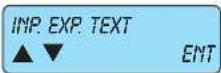
7.3.6 The INPUT EXPANSION TEXTS are texts associated to each input module expansion.
- Press ENT to enter the settings.
ENT
EXP NUM.: 1 [MAX 4]
PAR|↓
EXP NUM.: 1 INP. EXP. 01
7.3.6.1 Select the INPUT MODULE NUMBER you wish to assign to a text.
- Enter the number of the module you wish to programme.
- With the down arrow PAR↓ go to the edit default text menu.
7.3.6.2 INPUT EXPANSION MODULE NUMBER you can programme the text for module no. 1.
• Following the table in point 7.3.1.1, enter the characters.
- Press ON to change from lower to upper case and vice versa.
- If you have to enter two letters the same one after the other, press ON twice.
- Once you have finished entering the text for module 1, you can move on to the text for module 2, etc.
- When you have finished with all modules, press ESC|← to exit and return to the previous input module text menu.
ESC|← to go back
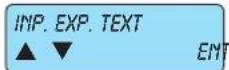
From the Input Expansion Text
PROGRAMMING MENU use the down arrow PAR↓ to go to the READER Text Programming menu.

7.3.7 TheRERDER TEXT is a text associated to each reader.
- Press ENT to enter the settings.
ENT
READER: 1 (MAX. 4)
PAR↓
READER: 1 READERS 1
7.3.7.1 Select the READER you wish to assign a text to.
- Enter the number of the module you wish to programme.
- With the down arrow PAR↓ go to the edit default text menu.
7.3.7.2 InREADERS: 1 you can programme the text for module 1.
- Following the table in point 7.3.1.1, enter the characters.
- Press ON to change from lower to upper case and vice versa.
- If you have to enter two letters the same one after the other, press ON twice.
- Once you have finished entering the text for module 1, you can move on to the text for module 2, etc.
- When you have finished with all modules, press ESC|← to exit and return to the previous READER Text menu.
ESC|← to go back

From the Reader Text PAR1↓ ming menu.
PROGRAMMING MENU use the down arrow PAR↓ to go to the Input expansion module 01710 text program-

7.3.8 The OUTPUT EXPANSION TEXTS are texts associated to each expansion 01710.
- Press ENT to enter the settings.
ENT
EXP. NUM.: 1 (MAX. 6)
PAR|↓
EXP. NUM.: 1 OUT. EXP. 01
7.3.8.1 Select the OUTPUT MODULE NUMBER you wish to assign to a text.
- Enter the number of the module you wish to programme.
- With the down arrow PAR|↓ go to the edit default text menu.
7.3.8.2 OUTPUT MODULE NUMBER: 1 you can programme the text for module 1.
• Following the table in point 7.3.1.1, enter the characters.
- Press ON to change from lower to upper case and vice versa.
- If you have to enter two letters the same one after the other, press ON twice.
- Once you have finished entering the text for module 1, you can move on to the text for module 2, etc.
- When you have finished with all modules, press ESC|← to exit and return to the previous READER Text menu.
ESC|← to go back
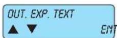
From the PAR↓
OUTPUT EXPANSION TEXT PROGRAMMING MENU use the down arrow PAR↓ to go to the Area Text Programming menu.

7.3.9 The BREA TEXT is text associated to each Area.
- Press ENT to enter the settings.
ENT
NUM. AREA: 1 (MAX. 8)
PAR|↓
NUM. AREA : 1 AREA 1
- If you have to enter two letters the same one after the other, press ON twice.
- Once you have finished entering the text for module 1, you can move on to the text for module 2, etc.
- When you have finished with all modules, press ESC|← to exit and return to the previous area text menu.
ESC|←
to go back

PAR|↓
From the AREA TEXT PROGRAMMING MENU use the down arrow PAR↓ to go to the Macro Text Programming menu.
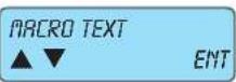
7.3.10 The MACRO TEXT is text associated to each Area.
- Press ENT to enter the settings.
ENT
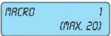
PAR|↓
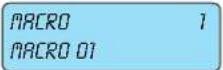
7.3.10.1 Select the MACRO NUMBER you wish to assign to a text.
- Enter the number of the module you wish to programme.
- With the down arrow PAR↓ go to the edit default text menu.
7.3.10.2 In MACRO 1 you can programme the text for macro 1.
- Following the table in point 7.3.1.1, enter the characters.
- Press ON to change from lower to upper case and vice versa.
- If you have to enter two letters the same one after the other, press ON twice.
- Once you have finished entering the text for module 1, you can move on to the text for module 2, etc.
- When you have finished with all modules, press ESC|← to exit and return to the previous Macro Text menu.
ESC|←
to go back

PAR|↓
From the Programming Menu STRING MACRO with the down arrow PAR↓ to go to the Programming menu for the By-me command strings.
7.3.11
The COM BY-ME strings are words associated to each command sent to the By-me system.
- Press ENT to enter the programming.
ENT
PAR|↓

7.3.11.1 Select the number of the command to assign a string to.
- Write the number of the command you wish to programme.
- Use the down arrow PAR↓ to go to the variation of the default string.
7.3.11.2 In COMMAND 1 it is possible to programme the string for command 1.
- Following the table in point 7.3.1.1, enter the digits.
- With the ON|→ button change from lower to upper case and vice versa.
- When having to enter two identical letters one after the other, press the ON|→ button twice.
- After writing the string of module 1, press ENT to confirm; after this move on to the string of module 2, etc.
- Having finished all the commands, press ESC|← to exit and return to the previous STR MENU. CON. BY-NE.
ESC|←
to go back

ESC|←
to go back
As there are no more parameters to be programmed, press ESC|← to return to the Text Settings menu level

Fromthe
PAR|↓
TEXT programming menu use the down arrow PAR↓ to go to the network card parameter programming menu.
7.4 In TCP - IP you programme all the parameters for the X-LAN network card.
- From the TCP - IP menu press ENT to enter the settings.
ENT

7.4.1 http ADDRESS you programme the address of the X-LAN network card.
- From the IP ADDRESS menu press ENT to enter the settings.
ENT
BYTE 0 10 (0 - 255)
PAR↓
BYTE 1 10 (0 - 255)
PAR↓
BYTE 2 10 (0 - 255)
PAR|↓
BYTE 3 10 (0 - 255)
ESC|←
to go back
7.4.1.1 In BYTE 0 you programme the first digit of the address.
- Enter the digits of the first byte directly (e.g. 10).
7.4.1.2 InBYTE 1 you programme the second digit of the address.
- Enter the digits of the second byte directly (e.g. 10.10).
7.4.1.3 In BYTE 2 you programme the third digit of the address.
- Enter the digits of the third byte directly (e.g. 10.10.10).
7.4.1.4 InBYTE 3 you programme the fourth digit of the address.
- Enter the digits of the fourth byte directly (e.g. 10.10.10.10).
As there are no more parameters to be programmed, press ESCI← to return to the TCP address programming menu level.

PAR|↓ Fromthe

ENT
BYTE 0 255 (0 - 255)
PAR|↓
BYTE 1 255 (0 - 255)
PAR|↓
BYTE 2 255 (0 - 255)
PAR↓
BYTE 3 0 (0 - 255)
ESC|←
to go back
IP ADDRESS menu use the down arrow PAR↓ to go to the local sub-network masking programming menu.
7.4.2 In NETMASK you programme the local sub-network mask address.
- From the NETMASK menu press ENT to enter the settings.
7.4.2.1 In BYTE 0 you programme the first digit of the address.
- Enter the digits of the first byte directly (e.g. 255).
7.4.2.2 InBYTE 1 you programme the second digit of the address.
- Enter the digits of the second byte directly (e.g. 255.255).
7.4.2.3 In BYTE 2 you programme the third digit of the address.
- Enter the digits of the third byte directly (e.g. 255,255,255).
7.4.2.4 InBYTE 3 you programme the fourth digit of the address.
- Enter the digits of the fourth byte directly (e.g. 255.255.255.0).
As there are no more parameters to be programmed, press ESC|← to return to the Netmask Address programming menu level.
From

PAR|↓
METRASK use the down arrow PAR↓ to go to the Gateway IP address programming menu.
ENT
7.4.3 In GATEWAY you programme the Gateway IP address. From the GATEWAY menu press ENT to enter the settings.
BYTE 0 10 (0 - 255)
PAR|↓
7.4.3.1 In BYTE 0 you programme the first digit of the address. - Enter the digits of the first byte directly (e.g. 10).
BYTE 1 10 (0 - 255)
PAR|↓
7.4.3.2 InBYTE 1 you programme the second digit of the address. - Enter the digits of the second byte directly (e.g. 10.10).
BYTE 2 10 (0 - 255)
PAR|↓
7.4.3.3 In BYTE 2 you programme the third digit of the address. - Enter the digits of the third byte directly (e.g. 10.10.10).
BYTE 3 10 (0 - 255)
ESC|←
7.4.3.4 InBYTE 3 you programme the fourth digit of the address. - Enter the digits of the fourth byte directly (e.g. 10.10.10.10).
As there are no more parameters to be programmed, press ESCI← to return to the Gateway Address Programming menu level.

PAR|↓
EN
From the
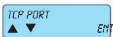
ENT
GATEWAY menu use the down arrow PAR↓ to go to the TCP port address programming menu.

PAR|↓
In TCP PORT you programme the network card listening port address. - From the TCP PORT menu press ENT to enter the settings.

ESC|←
to go back
7.4.4.1 In BY ALARM PORT you programme the network card listening port address for the By-alarm system. - Press Clear (CLR) and enter the door digits directly.
7.4.4.2 In TCP PORT you programme the network card listening port address for the By-me system. - Press Clear (CLR) and enter the door digits directly (e.g. 8030).
As there are no more parameters to be programmed, press ESC|← to return to the TCP Port Address Programming menu level.
PAR|↓
ENT
TCP PORT MENU use the down arrow PAR↓ to view the Access Code programming menu.
From the

ENT
EN
In SYSTEM PIN you set the six-digit numerical data exchange recognition code. - From the SYSTEM PIN menu press ENT to enter the settings.
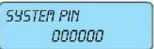
ESC|←
to go back
7.4.5.1 Write the SYSTEM PIN which must be the same as the one set in the By-alarm Manager software. - Enter the six-digit code directly.
As there are no more parameters to be programmed, press ESCI← to return to the SYSTEM PIN programming menu level.
By-alarm
Control Programming
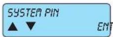

to go back
As there are no more parameters to be programmed, press ESC|← to return to the TCP - IP Programming menu level.
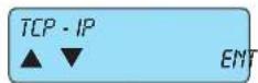
Fromthe

TCP - IP menu use the down arrow PAR↓ to go to the Macro Programming menu.
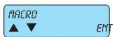
7.5 In MACROyou programme all the functions of the control unit macro-instructions.
- From the MACRO menu press ENT to enter the settings.


7.5.1 Select the NUMBER OF THE MACRO to be programmed, or the number of the macro to be programmed.

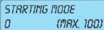


7.5.2 ISTARTING MODE you programme the event that will trigger the macro.
- Enter the number of the mode, selecting from those shown in the first column of the following table.
7.5.3 In STARTING TYPE you programme the second parameter of the event triggering the macro.
- Enter the number of the type, selecting from those shown in the second column of the following table.
7.5.4 I&TOP MODE you programme the event that will stop the macro.
- Enter the number of themode, selecting from those shown in the first column of the following table.
7.5.5 I6TOP TYPE you programme the second parameter of the event stopping the macro.
- Enter the number of the type, selecting from those shown in the second column of the following table.
| Progr. | Type | Function description |
| 0 | Null event | |
| 1 | 1 - 24 | Zone Alarm [1 - 24] |
| 2 | 1 - 24 | Reset from Zone Alarm [1 - 24] |
| 3 | 1 - 24 | Zone Exclusion [1 - 24] |
| 4 | 1 - 24 | Zone Re-inclusion [1 - 24] |
| 5 | 1 - 24 | Anti-Tampering Zone [1 - 24] |
| 6 | 1 - 50 | Enter User Code [1 - 50] |
| 6 | 129 - 178 | Enter Emergency User Code [1 - 50] |
| 7 | xx | See following table |
| 8 | 1 - 24 | Zone Multiple Alarm [1 - 24] |
| 9 | 1 - 24 | Reset from Zone Multiple Alarm [1 - 24] |
| 10 | 1 - 24 | Zone Multiple Anti-tampering Alarm [1 - 24] |
| 11 | 1 - 24 | Zone Multiple Anti-tampering Reset [1 - 24] |
| 12 | 1 - 4 | Keypad Anti-tampering Alarm [1 - 4] |
| 13 | 1 - 4 | Keypad Anti-tampering Reset [1 - 4] |
| 14 | 1 - 4 | Anti-tampering Input Alarm on zone expansion 01709 [1 - 4] |
| 15 | 1 - 4 | Anti-tampering Input Alarm Reset on zone expansion 01709 [1 - 4] |
| 16 - 20 | = = = | Values not used |
| 21 | 1 - 24 | Automatic Zone Exclusion [1 - 24] |
| 22 | 1 - 24 | Re-inclusion from Automatic Zone Exclusion [1 - 24] |
| 23 | 0 | No Control unit Network |
| 24 | 0 | Restore Control unit Network |
| 25 | 0 | Control unit Battery Low |
| 26 | 0 | Restore Control unit Battery |
| Progr. Type Function description | |
| 27 0 No Control unit Battery | |
| 28 == Value not used | |
| 29 1 - 8 Area ON on [1 - 8] | |
| 30 1 - 8 Turned off from | Area ON on [1 - 8] |
| 31 1 - 8 Area INT on [1 - 8] | |
| 32 1 - 8 Turned off from | Area INT on [1 - 8] |
| 33 1 - 8 Area PAR on [1 - 8] | |
| 34 1 - 8 Turned off from | Area PAR on [1 - 8] |
| 35 1 - 24 Zone Masking | Alarm [1 - 24] |
| 36 0 Installer ID Entry [0] | |
| 37 1 - 4 Incorrect code on Keypad [1 - 4] | |
| 38 1 - 8 Start Area Suspension [1 - 8] | |
| 39 1 - 8 End Area Suspension [1 - 8] | |
| 40 == Value not used | |
| 41 1 - 8 Automatic Area on [1 - 8] | |
| 42 1 - 8 Automatic Area off [1 - 8] | |
| 43 1 - 24 Activate Output [1 - 24] | |
| 44 1 - 24 Deactivate Output [1 - 24] | |
| 45 == Values not used | |
| 46 == Values not used | |
| 47 - 55 == Values not used | |
| 56 1 - 4 Keypad lock [1 - 4] | |
| 57 1 - 4 Keypad release [1 - 4] | |
| 58 1 - 4 Macro Activation [1 - 4] | |
| 59 1 - 20 Lock Macro [1 - 20] | |
| 60 1 - 20 Reset Macro [1 - 20] | |
| 61 == Values not used | |
| 62 1 - 8 Programmable Time Switch Deactivated for Area [1 - 8] | |
| 63 1 - 8 Programmable Time Switch Activated for Area [1 - 8] | |
| 64 1 - 6 Anti-tampering Input Alarm on output expansion 01710 [1 - 6] | |
| 65 1 - 6 Anti-tampering Input Alarm Reset on output expansion 01710 [1 - 6] | |
| 66 - 67 == Values not used | |
| 68 1 - 8 Non-routine Area on [1 - 8] | |
| 69 == Values not used | |
| 70 1 - 4 Communication | Anti-Tampering Alarm 01709 [1 - 4] |
| 71 1 - 6 Communication | Anti-Tampering Alarm 01710 [1 - 6] |
| 72 1 - 4 Keypad Communication Anti-Tampering Alarm [1 - 4] | |
| 73 1 - 50 Correct TAG Reading [1 - 50] | |
| 74 1 - 4 Connector Tag not valid [1 - 4] | |
| 75 1 - 50 User Code enabled [1 - 50] | |
| 76 1 - 50 User Code disabled [1 - 50] | |
| 77 1 - 24 Reset Zone [1 - 24] | |
| 78 == Value not used | |
| 79 Gate Locked | |
| 80 Gate Unlocked | |
| 81-107 == Values not used | |
| 108 1 - 4 Connector Anti-Tampering Alarm [1 - 4] | |
| 109 1 - 4 Connector Communication Anti-Tampering Alarm [1 - 4] | |
| 110 1 - 4 Reset Connector Tamper [1 - 4] | |
| 111 | 1 - 32 By-me command [1 - 32] |
| 112 | 1 - 50 User code from By-me [1 - 50] |
| 113 | 1 - 50 Emergency code from By-me [1 - 50] |
- Only for MODE 7 these values can be entered in the TYPE:
| Progr. Type 01700 Function description | |
| 7 0 - 53 Values not used | |
| 7 54 System Reset (Watch Dog) | |
| 7 55 Change Codes | |
| 7 56 Reset Codes | |
| 7 57 Programming reset to Default levels | |
| 7 58 Installer Code 1 | |
| 7 59 Installer Code 2 | |
| 7 60 No Telephone Line | |
| 7 61 Restore Telephone Line | |
| 7 62 Send Events Log | |
| 7 63 Telephone Call Interruption | |
| 7 64 Change system Date | |
| 7 65 Robbery Message | |
| 7 66 Fire Message | |
| 7 67 Doctor Message | |
| 7 68 Remote Programming OK | |
| 7 69 Remote Programming failed | |
| 7 70 Remote Access Denied | |
| 7 71 Control unit anti-tampering | |
| 7 72 Reset Control Unit Anti-Tampering | |
| 7 73 Self-test | |
| 7 74 Start User or Installer remote function | |
| 7 75 End User or Installer remote function | |
| 7 76 End PC Local Connection | |
| 7 77 Start PC Local Connection | |
| 7 78 Start Code Shut-Down Slot | |
| 7 79 End Code Shut-Down Slot | |
| 7 80 Start Zone Test Period | |
| 7 81 End Zone Test Period | |
| 7 82 Alarm Relay 1 Activated (dual change-over) | |
| 7 83 Alarm Relay 1 Deactivated (dual change-over) | |
| 7 84 No GSM signal on 01706 | |
| 7 85 Restore GSM Signal on 01706 | |
| 7 86 Relay 2 Activated (single change-over) | |
| 7 87 Relay 2 Deactivated (single change-over) | |
| 7 88 Values not used | |
| 7 89 Values not used | |
| 7 90 Start Pre-alarm | |
| 7 91 Reset Pre-alarm | |
| 7 92 S/M Not Charged | |
| 7 93 S/M Recharged | |
| 7 94 S/M Expiring | |
| 7 113 Reset network card | |
| 7 118 GSM Jamming Alarm | |
| 7 119 Reset Jamming GSM Alarm | |
| 7 122 Self-learning | |
PAR|↓
SCHEDULER BLOCK
NO
PAR|↓
7.5.6 A YES in STOPPED BY SCHEDULER the macro can be stopped by the Scheduler.
- Press CLR to change the settings.
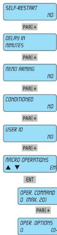
flowchart
graph TD
    A["SELF-RESTART NO"] --> B["PAR ↓"]
    B --> C["DELAY IN MINUTES"]
    C --> D["PAR ↓"]
    D --> E["NEAO ARMING NO"]
    E --> F["PAR ↓"]
    F --> G["CONDITIONED NO"]
    G --> H["PAR ↓"]
    H --> I["USER IO NO"]
    I --> J["PAR ↓"]
    J --> K["MACRO OPERATIONS ▲ ▼ ENT"]
    K --> L["ENT"]
    L --> M["OPER. COMMAND 0 (MAX. 20)"]
    M --> N["PAR ↓"]
    N --> O["OPER. OPTIONS 0 (0-"]
7.5.7 A YES in AUTORESTARTallows the macro to continue to run automatically.
- Press CLR to change the settings.
7.5.8 DELRY IN MINUTES you set the time base of any delay.
- Press CLR to change the settings.
7.5.9 With YES iREMO ACTIVATION when activated the macro is recorded in the control unit events memory.
- PressCLR to change the settings.
7.5.10 A YES in CONDITIONED means that the "stop macro" event is not considered an effective macro stop, but a starting condition for the macro itself.
- Press CLR to change the settings.
7.5.11 A YES in USER ID allows the User to activate the macro using his own code.
- Press CLR to change the settings.
7.5.12 In MACRO OPERATIONS you programme the operations the macro has to run.
- Press ENT to enter the settings.
7.5.12.1 In OPERATIONS 1 COMMAND you enter the first of the 16 commands to be run by the macro.
Enter the number of the required command, consulting the table below.
7.5.12.2 In OPERATIONS 1 OPTIONS enter the parameter completing the command of the operation just programmed.
- Enter the number of the required option, consulting the table below.
| Progr. | Options | Function description |
| 0 | 0 | No function |
| 1 | 1 - 8 | Area ON mode on [1 - 8] |
| 2 | 1 - 8 | Area INTERNAL mode on [1 - 8] |
| 3 | 1 - 8 | Area PARTIALISED mode on [1 - 8] |
| 4 | 1 - 8 | Area off [1 - 8] |
| 5 | 1 - 24 | Exclude zone [1 - 24] |
| 6 | 1 - 24 | Re-include zone [1 - 24] |
| 7 | 1 - 24 | Activate output [1 - 24] |
| 8 | 1 - 24 | Deactivate output [1 - 24] |
| 9 | 1 - 20 | Start Macro [1 - 20] |
| 10 | 1 - 20 | Stop Macro [1 - 20] |
| 11 | 1 - 20 | Reset Macro [1 - 20] |
| 12 | 1 - 20 | Enable Macro [1 - 20] |
| 13 | 1 - 20 | Disable Macro [1 - 20] |
| 14 | 1 - 50 | Lock User Codes [1 - 50] |
| 15 | 1 - 50 | Release User Codes [1 - 50] |
| 16 | 1 - 4 | Keypad lock [1 - 4] |
| 17 | 1 - 4 | Keypad Release [1 - 4] |
| 18 | 1-32 | By-me command [1-32] |
| 19 | 0 - 255 | Entry of a Delay in minutes or seconds |
ESC|←
to go back
As there are no more parameters to be programmed, press ESC|← to return to the Macro Operations menu level.

ESC|←
to go back
Having finished programming all the Macros, press ESC|← to exit the Macro programming and return to the main Macro menu.
By-alarm
Control Programming
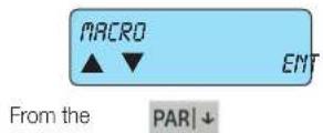
MACRO menu use the down arrow PAR↓ to go to the Events Memory Viewing menu.

7.6 In view memory you can check all the events occurring on the control unit, showing the date and time.
- Press ENT to enter the viewing mode.
Events Memory: • the control unit has a memory used to record all the fault, arming and disarming events with date and time, the codes entered and alarm and zone reset states; there are 500 recorded events which are automatically updated, deleting the oldest ones.
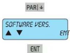
7.7 In the SOFTWARE VERSION menu you can view the control unit software version.
- Press ENT to enter the settings.

7.7.1 In the SOFTWARE VERSION menu you can check the software version installed in the control unit and the relative release.
ESC|← to go back
As there are no more parameters to be programmed, press ESC|← to return to the Software Version Settings Menu.
From the SOFTWARE VERSION menu use the down arrow PAR↓ to go to the Control unit Default Programming menu.
7.8 In the DEFAULT PROGRAMMING MENU you can reset the control unit programming to the default values.
- Press ENT to enter the settings.
ENT

7.8.1 Answer the question ARE YOU SUREP.
- Press ENT to confirm the reset to default values.
- Press ESC|← to cancel the function.
a) having pressed ENT, wait for the end of the reset. You will automatically return to the default programming menu.
b) having pressed ESC|←, you return to the default programming menu.
ESC|← to go back
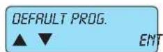
DEFAULT PROGRAMMING 1 menu use the down arrow PAR↓ to go to the Control unit Default Programming menu.
PAR|↓

7.9 In ACCESS CONTROL you programme the advanced functions of the READERS.
- Press ENT to enter the settings.
ENT

ENT
7.10 IACTIVE LEDS you programme the reader on which the LEDs will display the control unit states.
- Press ENT to enter the settings.

7.10.1 Select the reader READERS 1 - 4 in which the LEDs are active.
- Enter the number 1-2-3-4 of the reader in which the LEDs must always be active; the indicator will come on to confirm correct programming.
To deselect the reader repeat the same operation.
Fast mode: button 9 selects all and button 0 deselects all.
- The reader is identified with the address given (see indications given in the reader installation manual).
- The readers in which the LEDs are not active will always be off; place the key near the reader to activate them and signal the control unit state.

to go back
As there are no more parameters to be programmed, press ESC← to return to the Active LED menu level.


to go back
As there are no more parameters to be programmed, press ESC|← to return to the Access Control menu level.


to go back
As there are no more parameters to be programmed, press ESCI← to return to the Controls Menu level.


From the CONTROLS menu use the down arrow PAR↓ to view the Scheduler menu.
8. Scheduler
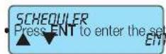
- In SCHEDULER you set all the Scheduler parameters.
ENT
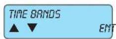
ENT

ITIME BANDS you programme the functions that the control unit must run automatically for every day of the week.
- Press ENT to enter the settings.
8.1.1 InMONDAYyou programme the operations the control unit will run on that day of the week.
- Press ENT to enter the settings.
- With the down arrow PAR↓ go to other days of the week.
ENT
- Enter the number of the operation you wish to programme.
- With the down arrow PAR↓ go to Programming all parameters of the chosen operation.
8.1.1.2 Programming the TIME the operation will be run at.
- Enter the time directly.
8.1.1.3 Programming the MINUTE the operation will be run at.
- Enter the minutes directly.
8.1.1.4 Programming the TYPE of operation run.
- Enter the number of the type directly, consulting the following table.
8.1.1.5 In AUXILIARIES enter the parameter completing the command of the operation just programmed.
- Enter the number of the auxiliary option, consulting the following table.
| Progr. Options | Function description | |
| 0 | 0 | No function |
| 1 | 1 - 8 | Area ON mode on [1 - 8] |
| 2 | 1 - 8 | Area INTERNAL mode on [1 - 8] |
| 3 | 1 - 8 | Area PARTIALISED mode on [1 - 8] |
| 4 | 1 - 8 | Area off [1 - 8] |
| 5 | 1 - 24 | Exclude zone [1 - 24] |
| 6 | 1 - 24 | Re-include zone [1 - 24] |
| 7 | 1 - 24 | Activate output [1 - 24] |
| 8 | 1 - 24 | Deactivate output [1 - 24] |
| 9 | 1 - 20 | Start Macro [1 - 20] |
| 10 | 1 - 20 | Stop Macro [1 - 20] |
| 11 | 1 - 20 | Reset Macro [1 - 20] |
| 12 | 1 - 20 | Enable Macro [1 - 20] |
| 13 | 1 - 20 | Disable Macro [1 - 20] |
| 14 | 1 - 50 | Lock User Codes [1 - 50] |
| 15 | 1 - 50 | Release User Codes [1 - 50] |
| 16 | 1 - 4 | Keypad lock [1 - 4] |
| 17 | 1 - 4 | Keypad Release [1 - 4] |
| 18 | 1-32 | By-me command [1-32] |
| 19 | 0 - 255 | Entry of a Delay in minutes or seconds |
PAR|↓

As there is no more programming to be done, return to OPERATION 1 .
ESC|←
to go back Having finished programming all the required operations, press ESC|← to exit the programming and return to Monday.

Fromthe
PAR|↓
MONDRY menu use the down arrow PAR↓ to go to the TUESDAYmenu; in this way the functions of all the days of the week can be programmed.
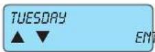
ESC|←
to go back
Having programmed all the operations for every day of the week, press ESC|← to return to the Time Bands menu.

PAR|↓Fromthe
TIME BANOS menu use the down arrow PAR↓ to go to the Holidays Programming menu.

8.2 In HOLIDAYS you programme the holiday periods in which the arming and disarming programmes will not be run by the control unit.
- Press ENT to enter the settings.
ENT

PAR|↓

PAR|↓
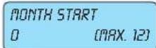
PAR|↓

PAR|↓

8.2.1 Select the number of HOLIDAY 1 to be programmed. - Enter the number of the holiday from the 16 possible options.
8.2.2 Programme the START DAY of the holiday period. - Enter the day of the start date.
8.2.3 Programme the START MONTH of the holiday period. - Enter the month of the start date.
8.2.4 Programme the END DAY of the holiday period. - Enter the day of the end date.
8.2.5 Programme the END MONTH of the holiday period. - Enter the month of the end date.
ESC|←
to go back
As there are no more parameters to be programmed, press ESC← to return to the Holiday Settings menu level.

ESC|← to go back
As there are no more parameters to be programmed, press ESC|← to return to the Scheduler Settings menu
PAR|↓ From the control unit
SCHEDULER menu use the down arrow PAR↓ to view the Phone communicator programming menu.
9. Telephone

- In TELEPHONE you programme all the parameters for the Phone communicator.
ENT
ENT
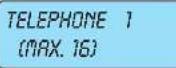
PAR|↓
PROTOCOL VOCRL
9.1 PHONE NUMBERS you programme the numbers and properties of the phone communications.
- Press ENT to enter the settings.
9.1.1 Select the PHONE NUMBER you wish to programme.
- Enter the phone number you wish to programme.
- With the down arrow PAR↓ go to the Programming all parameters of the chosen telephone number.
Important: Panic, theft, tampering events must be associated to at least the first phone number.
This guarantees that in the event of more than one event at the same time panic, theft and tampering are transmitted as a priority.
9.1.2 InPROTOCOL you programme the communication methods of the phone communicator for the chosen number.
- Enter the number of the required mode by consulting the table below.
| Prog. | Function type | Description |
| 0 | SIA | Digital format for digital receivers in SIA protocol |
| 2 | VOCAL | Format for sending vocal messages that are preset and pre-recorded in the control unit |
| 3 | CONTACT-ID | Digital format for digital receivers in CONTACT ID protocol |
| 4 | SMS | Format for sending SMS messages that are preset and pre-recorded in the control unit |

ENT

9.1.3 InNUMBER DIGITS you programme the digits comprising the code.
• From the NUMBER FIGURES menu press ENT to enter the settings.
ESC|← to go back
9.1.3.1 Programme the phone number that will be called.
- Press CLR to delete the current number.
- Enter thenew number.
- Press ENT to confirm the new number.
As there are no more parameters to be programmed, press ESC|← to return to the Number Digits Programming menu level.
PAR|↓
From the NUMBER DIGITS programming menu use the down arrow PAR↓ to go to the Communication Protocol Programming menu.

9.1.4 The CUSTOMER CODE is the code sent in SIA and CONTACT ID digital communications identifying the caller. In the protocol VOCAL corresponds to the voice message index for the area of interest.
- Press ENT button to enter the programming.
- It is indispensable for reception and control centres to recognise the user calling; to know which code to enter, the same centre must always be contacted to provide the necessary information.
- For the SIA protocol this is composed of 6 digits, starting from the left.
- For the CONTACT ID protocol this is composed of 4 digits, starting from the left.
- For the VOCAL protocol the last digit identifies the initial message to use among those available and recorded for the areas.
Note: The customer code 000000 by default in any case uses message no.1.
ENT
CUSTOMER CODE 000000
9.1.4.1 Programme the value of the chosen code.
- Press CLR to delete the current code.
- Write the new code.
- Press ENT to confirm the new code
ESC|←
to go back
As there are no more parameters to be programmed, press ESC|← to return to the Customer Code Programming menu level.

From
PAR↓
CUSTOMER CODE use the down arrow PAR↓ to go to the Call Attempts with previously selected phone number association menu.

9.1.5 TheTTEMPTS refer to the maximum number of calls the control unit will make to the chosen phone number if there is no reply.
- Enter the required number.
PAR|↓

9.1.6 A YES STOP CALLS enables the interruption of the phone calls when the user called presses button 4 on the phone allowing the user to directly activate remote connection by pressing button 3 on the phone.
- PressCLR to change the settings.
PAR↓

9.1.7 IZONE ALARM you programme the zones activating the phone calls.
ZONE ALAR From menu press ENT to enter the settings.
ENT
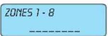
PAR↓
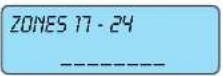
ESC|←
to go back
9.1.7.1 With ZONE 1 - 8 you programme which zone will cause the activation of the phone call in the event of an alarm.
- For each zone group, write the number 1-2-3-4-5-6-7-8 for the zones which must activate the phone calls.
Fast mode: button 0 selects all and button 9 deselects all. - The symbol will come on to confirm the association.
• To remove the association write the required number.
As there are no more parameters to be programmed, press ESC|← to return to the Zone Alarms menu.

From
PAR↓
ZONE ALARM use the down arrow PAR↓ to go to the Zone alarm reset association menu with the previously chosen telephone number.

9.1.8 IRESTORE ZONE you programme the zones activating the phone calls.
RESTORE ZONE Promthenu press ENT to enter the settings.
ENT
ZONES 1-8
[EMPTY]
PAR|↓
ZONES 17 - 24
____
ESC|←
to go back
9.1.8.1 With ZONE 1 - 8 you programme which zone activates the phone call in the event of an alarm reset.
- For each zone group, write the number 1-2-3-4-5-6-7-8 for the zones which must activate the phone calls.
Fast mode: button 0 selects all and button 9 deselects all. - The symbol will come on to confirm the association.
• To remove the association write the required number.
As there are no more parameters to be programmed, press ESCI← to return to the Reset from Zone Alarm menu level.
From

ESC|←
TELEPHONE 1 (MAX. 16)
to go bad ESC | ←

PAR|↓

ENT
SEND ON REPLY YES
PAR|↓
ATTEMPTS PAUSE 60 (0 - 255 SEC)
PAR|↓
VOCAL REPETITION 3 (MAX. 8)
PAR|↓
PSTM RINGS 0 (MAX. 14)
PAR|↓
GSM RINGS 0 (MAX. 14)
PAR|↓
SKIP VOICE MAIL NO
PAR|↓
AUX CSM NUMBER ▲ ▼ EM7
ENT
AUX CSA NUMBER **************************
ESC|← to go back
AUX CSM NUMBER ▲ ▼ ENT
PAR|↓
RESET ZONE use the down arrow PAR↓ to go to the Telephone 1 programming menu.
9.1.9 By selecting number 2, you select Phone Number 2 and scrolling through the programming seen above for Phone Number 1 (starting from point 9.1.1) you can set all the parameters.
- When you have finished programming all the required numbers, press to exit the single code programming and return to the previous Phone Numbers menu.
From the TELEPHONE NUMBERS menu use the down arrow PAR↓ to go to the Telephone Parameters Programming menu.
9.2 TELEPHONE PARAMETERS you programme all the parameters for the telephone communications. ENT to enter the settings.
9.2.1 A YES on SEND ON REPLY makes the control unit send programmed vocal messages after a vocal reply to a call (e.g. Hello?).
A NO makes the message start in any case, without waiting for a reply.
- Press CLR to change the settings.
9.2.2 ATTEMPTS PRUSE refers to the time in seconds between the second and third attempt if the set phone calls (see point 9.1.7) obtain no reply.
- Enter the seconds of the interval.
9.2.3 VOCAL REPETITION is the number of times the whole vocal message must be repeated for each voice call.
- Enter the required number.
9.2.4 In PSTN RINGS you programme the number of phone rings read by the control unit on the cabled line; after this number the User Remote Connection will be activated.
- Enter the required number.
9.2.5 In GSM RINGS you programme the number of phone rings read by the control unit on the GSM line; after this number the User Remote Connection will be activated.
- Enter the required number.
9.2.6 A YES on SKIP VOICE MAIL makes the control unit activate the function for User Remote Connection calls.
- By programming NO, the control unit will only check the number of phone rings seen in point 9.2.7.
9.2.7 In AUXILIARY CSM NUMBERprogramme the number of the message service centre when using a telephone operator other than that indicated in the list in point 9.1.2.
- From the AUX CSA NUMBER menu press the ENT button to enter the programming.
Programme the message service centre number.
- Press CLR to delete the current number.
- Write the new number.
- Press ENT to confirm the new number.
From the AUXILIARY CSA NUMBER use the down arrow PAR↓ to go to the SIM programming menu.

9.2.8 A YES OR RECHARGEABLE SIM sets the inserted SIM as rechargeable, so it will be possible to know the residual credit and programme the annual expiry date. ATTENTION: Would customers please note that Vimar cannot guarantee the operation of the residual credit verification service on SIM cards, as this function depends on the operating choices of the individual mobile phone operator.
- PressCLR to change the settings.
9.2.9A YES on NUMBER RECOGNITION makes the control unit able to recognise the calling number from those set and directly activate the user remote connection by pressing button 3 on the phone, and if programmed, the active outputs. - PressCLR to change the settings.

9.2.10 RING BACK is an unused function. - Press CLR to change the settings.

As there are no more parameters to be programmed, press ESC|← to return to the Telephone Parameter Settings menu level.
Fromthe

PAR|↓
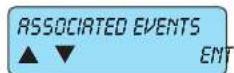
TELEPHONE PARAMETERS menu use the down arrow PAR↓ to go to the Associated Events Programming menu.
IRASSOCIATED EVENTS you programme the events that must be communicated for every phone number. Press ENT to enter the settings.
ENT

PAR|↓
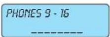
ESC|←
to go back
PAR↓

PAR|↓

PAR|↓

PAR|↓
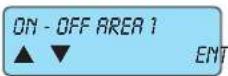
PAR↓

PAR|↓
9.3.1 For all the following events to be associated to the telephone numbers, comply with the following instructions: • for each group of phone numbers, enter the number 1-2-3-4-5-6-7-8 for the digits to be associated.
Fast mode: button 0 selects all and button 9 deselects all.
• The symbol will come on to confirm the association.
• To remove the association write the required number.
- Press ESC|← to exit the programming.
9.3.2 In TAMPER you program which phone numbers will be sent the communication of the tamper-proof device, siren fault, anti-theft device fault and sensor fault.
9.3.3 In MASKING you programme the telephone number the masking communication is sent to.
9.3.4 In BYPASS ZONE you programme which phone numbers will be sent notification of the zone bypassed.
9.3.5 In ON-OFF AREA 1 you programme the phone numbers which will be sent the arming and disarming communication for Area 1.
9.3.6 In ON-OFF AREA 8 you programme the phone numbers which will be sent the arming and disarming communication for Area 8.
By-alarm
Telephone
| NO BATTERY▲▼ENT | 9.3.7 | NO BATTERY you programme the phone numbers which will be sent the no mains voltage communication. |
| PARI↓ | 9.3.8In | NO BATTERY you programme the phone numbers which will be sent the no battery communication. |
| NO BATTERY▲▼ENT | 9.3.9 | LOW BATTERY you programme the phone numbers which will be sent the low battery communication. |
| PARI↓ | 9.3.10 | InBATT.LOU RFprogramme the telephone number to send the low battery level message relating to any one of the radio frequency detectors. |
| BATT.LOU RF▲▼ENT | 9.3.11 | IsURVIVALyou programme the phone numbers to be sent the notification on the selftest completed on the control unit power supplies as programmed in point 7.2.2. |
| PARI↓ | 9.3.12 | WATCHDOGrefers to a special control function on the control unit microprocessor; in the event of serious electrical disturbances, this check restarts the system without losing any date in the control unit. Here you can programme the phone numbers to be sent a notification of the restart. |
| SELF-TEST▲▼ENT | 9.3.13 | You can programme the phone numbers to be sent the notification thatUSER IDhas been entered in the keypad. |
| PARI↓ | 9.3.14 | You can programme the phone numbers to be sent the notification thatEMERGENCY USER IDhas been entered in the keypad. |
| WATCHDOG▲▼ENT | 9.3.15In | MEDICAL DISPATCHyou programme which phone number to send a silent panic call to by pressingINTand 4on the keypad together. |
| PARI↓ | 9.3.16In | PANIC DISPATCHyou programme which phone number to send a silent medical call to by pressingINTand6 on the keypad together. |
| EMERGENCY CODE▲▼ENT | 9.3.17 | IfIRE DISPATCHyou programme which phone number to send a silent fire call to by pressingINTand 4on the keypad together. |
| The Emergency ID is the code originating from the User ID to which a unit is added. | 9.3.18 | IsIM NOT CHARGEDyou programme which phone number to send a communication to when the credit reaches 5 EUR.ATTENTION: Would customers please note that Vimar cannot guarantee the operation of the residual credit verification service on SIM cards, as this function depends on the operating choices of the individual mobile phone operator. |
| PARI↓ | 9.3.19In | SIM EXPIRYyou programme the phone number to send a communication to when the programmed expiry date is reached. |
| MEDICAL DISP.▲▼ENT | 9.3.19In | The SIM duration is one year from the last top up and is a parameter which must be programmed by the user whenever the sim is charged. |
| PARI↓ | 9.3.19In | You are advised to enter a date at least one month prior to the effective expiry date. |
| PANIC DISP.▲▼ENT | 9.3.19In | An expired SIM cannot be renewed or charged, and the whole amount of the residual credit is lost. |
| PARI↓ | 9.3.19In | As there are no more parameters to be programmed, pressESC←to return to the Associated Events Settings menu level. |
| AVAIL FIRE▲▼ENT | 9.3.19In | To go back |
| PARI↓ | 9.3.19In | From theASSOCIATED EVENTSmenu use the down arrowPARI↓to view the Vocal Message Programming menu. |
| SIM NOT CHARGED▲▼ENT | 9.3.19In | To go back |
| PARI↓ | 9.3.19In | From theASSOCIATED EVENTSmenu use the down arrowPARI↓to view the Vocal Message Programming menu. |

9.4
In MOCAL MESSAGES menu you programme the communication method for each control unit input.
- Press ENT to enter the settings.
ENT

PAR|↓
VOCAL MESSAGES 1 (MAX. 12)
9.4.1 Select NUMBER OF THE ZONE you wish to programme.
e zone number you wish to programme.
- With the down arrow PAR↓ go to the Programming of all parameters of the chosen zone.
9.4.2 In VOCAL MESSAGES you programme the type of communication for the chosen zone.
Examples: by programming type 1 (theft) for zone 1, an alarm in this zone will send a communication of the following type for digital protocols, voice communications and SMS messages: THEFT ALARM ZONE 1.
- programming type 6 (panic), the communication will be: ZONE 1 PANIC ALARM
Enter the number of the required mode by consulting the table below:
PAR|↓
| Prog. | Function type | Description |
| 1 | Theft | Theft alarm in the associated zone |
| 2 | Tamper | Tamper (anti-tamper) alarm in the associated zone |
| 3 | Fire | Fire alarm in the associated zone |
| 4 | Gas | Gas alarm in the associated zone |
| 5 | Technical | Technical alarm in the associated zone (generic technical) |
| 6 | Panic | Panic alarm in the associated zone |
| 7 | Doctor | Medical alarm in the associated zone |
| 8 | Emergency | Emergency alarm in the associated zone |
| 9 | Heat | Heat alarm in the associated zone |
| 10 | Cold | Cold alarm in the associated zone |
| 11 | Flooding | Flooding alarm in the associated zone |
| 12 | Sprinkler | Sprinkler Alarm for the associated zone (sprinkling in progress) |

PAR|↓
NUM. ZONE: 1 (MAX. 24)
9.4.3 With CUSTOMISED WORD you can add a word to specify the alarm in the zone that caused it to the vocal message.
Examples: • by programming type 1 (theft) for zone 1 and associating word 1 programmed with the entry, an alarm in this zone will send the following type of message for voice communications: THEFT ALARM ZONE 1 ENTRY.
- Enter the number of the word to add.
• To record customised words see point 9.5.2.
9.4.4 As there are no more parameters to be programmed for the selected zone, return to the ZONE NUMBER programming menu.
- Selecting number 2, you select Zone 2 and, scrolling through the programming seen above for Zone 1 (starting from point 9.4.1) you can programme all the parameters.
- When you have finished programming all the required numbers, press ESC|← to exit the individual zone programming and return to the previous Vocal Messages menu.
ESC|←
to go back

ENT
PAR↓

9.5
From the VOCAL MESSAGES menu use the down arrow PAR↓ to go to the Recordings Programming menu.
RECORDINGS you record the user address, which is an integral part of the vocal communication and any customised words (see point 9.4.3). These messages, lasting 10 s, are recorded by speaking through a phone with buttons that is connected to the voice synthesis module 01713; the recording can be started/stopped either with the keypad 01705 or with the connected phone's buttons.
- Press ENT to enter the settings.
ENT
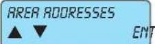
ENT
9.5.1 AREA ADDRESSES you record the user addresses for each area; every message will precede all voice communications for this area. (e.g. Home of Rossi Cario - Piazza Europa 32 - Padua).
- Press ENT to enter the settings.
MESSAGE (MAX. 8)
PAR↓
LISTEN TO BESS.


ie 10 seconds
9.5.1.1 In MESSAGE # you record the first of the 8 possible user addresses preceding all vocal phone communications (e.g. Home of Rossi Carlo - Piazza Europa 32 - Rome).
9.5.1.2 InLISTEN TO MESSAGEyou can check the recorded message.
• Press ENT to change the settings.
available recording scroll on the keypad display.
PAR|↓
RECOROING


e 10 seconds
9.5.1.3 InRECORDING you record the message for the user address.
• Press ENT to change the settings.
available recording scroll on the keypad display.
- Select message 2 and scroll through the programming seen above for Message 1 (starting from point 9.5.1.1 in this page) you can record all the other possible addresses.
- Having finished programming all the required numbers, press ESC|← to exit the single zone programming and return to the previous Area Addresses Settings menu.
ESC|←
to go back
AREA ADDRESSES


ENT
PAR↓
From the
RECORD WORDS


the number of (MAX. 24)
PAR|↓
LISTEN TO MESS.


m = 311
m = 311
m = 311
m = 311
m = 311
m = 311

ESC|← to go back
As there are no more parameters to be programmed, press ESC|← to return to the Telephone Settings menu level.

ESC|← to go back
As there are no more parameters to be programmed, press ESC|← to completely exit the Control unit Programming.
SYSTEM TEST ^1 Present to enter the system test. ENT=YES ESC=NO
ENT
CONTROL UNIT TAMPER CLOSED
All the CONTROL UNIT TAMPER i.e. the anti-tamper functions on the system, are closed.
- Press the arrow key PAR↓ to continue the test.
PAR|↓
ZONES 1-8 A
To assess ZONES 1 - 8, see the table to the side.
- Press the arrow key PAR↓ to continue the test.
PAR|↓
ZONES 17-24 ???????
In ZONES 17 - 24, the zones from 17 to 24 are not programmed.
- Press the arrow key PAR↓ to continue the test.
PAR|↓
IMP. EXP. 1 - 4
the IMP.-EXP. 1 - 4 i.e. the input expansion modules, are functioning correctly.
- Press the arrow key PAR↓ to continue the test.
PAR↓
KEYPADS 1-4
The KEYPADS 1 - 4, i.e. the input expansion modules, are functioning correctly.
- Press the arrow key PAR↓ to continue the test.
PAR|↓
OUTPUT EXP. 1 ... 6
The OUTPUT EXPANSIONS1 - & are functioning correctly.
- Press the arrow key PAR↓ to continue the test.
ESC|← to go back
As there are no more parameters to be programmed, press ESC|← to completely exit the Control unit Programming.
| code | description |
| TO | alarm |
| M | masking |
| T | tamper |
| X | not used |
| ? | not associated |
WE 04 JUN 15:48 VIMAR 07700
Section 2
Programming the control unit with By-Alarm Manager software
Procedure to enable settings with By-alarm Manager
The connection between the PC and the By-alarm control unit is done via the configuration interface 01725 following the instructions given in the instruction sheet.
1. CONNECT THE CONTROL UNIT (CONNECTOR CN3) TO THE PC (USB PORT) VIA THE SETTINGS INTERFACE 01725
Note: If the PC has only USB ports and no serial port simply use a USB-RS232 converter.
The installation of the converter driver will allow the operating system to map the USB port as a virtual COM to which a number will be assigned (visible from the Windows
Control unit) with which it will univocally be identified; this number is the one to enter in the By-alarm Manager software in the Connection to control unit window.
2. PREPARE THE CONTROL UNIT FOR CONNECTION:
a) Use keypad 01705 to enter the programming menu entering the installer ID (the default code for all control units is 123456).
b) Activate the connection with the PC.
- select the Settings e menu and press ENT.
- scroll through the menu as far as PC <-> Control unit and press ENT.
- press CLR to view YES.
- press ESC to exit the menu.
d) press ESC repeatedly to completely exit the control unit programming menu.
3. PREPARE THE PC FOR CONNECTION:
a) Run the By-alarm Manager software and open the system programming window.
b) Select the folder New to open a new system and enter the characterising data (Name, etc.).
b) Select New-> System Programming and indicate the type of control unit installed (art. 01700 or 01700.120).
4. START COMMUNICATION:
a) Select the control unit just set up; the general System Programming screen is displayed.
b) Click on Connect and set the required COM port by clicking on Open Peripherals Management.
c) Click on Start connection to start the communication session.
IMPORTANT: At the end of the local connection disable the connection between the PC and the control unit; to do so, run the procedure indicated in point 2 setting NO (press CLR) in option PC <--> Control unit.
If the Web Server 01945-01946 and the By-alarm interface to the Ethernet network 01712 are present in the system, do not run the disconnection procedure.
System card
| By-alarm burglar alarm system | ||
| Date of installation:Surname and name:Address:Telephone | ||
| Zone | Associated devices Notes | |
| 1 | ||
| 2 | ||
| 3 | ||
| 4 | ||
| 5 | ||
| 6 | ||
| 7 | ||
| 8 | ||
| 9 | ||
| Zone | Associated devices Notes | |
| 10 | ||
| 11 | ||
| 12 | ||
| 13 | ||
| 14 | ||
| 15 | ||
| 16 | ||
| 17 | ||
| 18 | ||
| 19 | ||
| 20 | ||
| 21 | ||
| 22 | ||
| 23 | ||
| 24 | ||
| AREA-Zone association | |
| Zones associated to AREA 1 | ON: |
| INT: | |
| PAR: | |
| Zones associated to AREA 2 | ON: |
| INT: | |
| PAR: | |
| Zones associated to AREA 3 | ON: |
| INT: | |
| PAR: | |
| Zones associated to AREA 4 | ON: |
| INT: | |
| PAR: | |
| Zones associated to AREA 5 | ON: |
| INT: | |
| PAR: | |
| Zones associated to AREA 6 | ON: |
| INT: | |
| PAR: | |
| Zones associated to AREA 7 | ON: |
| INT: | |
| PAR: | |
| Zones associated to AREA 8 | ON: |
| INT: | |
| PAR: | |

natural_image
Solid yellow horizontal bar with no text or symbols
natural_image
Completely blank white image with no visible content, text, or symbols.
natural_image
Blank white image with no visible content, text, or symbols.
natural_image
Blank white image with no visible content, text, or symbols.
natural_image
Blank white image with no visible content, text, or symbols.
natural_image
Blank white image with no visible content, text, or symbols.
natural_image
Blank white image with no visible content, text, or symbols.
natural_image
Blank white image with no visible content, text, or symbols.
natural_image
Blank white image with no visible content, text, or symbols.
natural_image
Blank white image with no visible content, text, or symbols.
natural_image
Blank white image with no visible content, text, or symbols.
natural_image
Blank white image with no visible content, text, or symbols.
natural_image
Blank white image with no visible content, text, or symbols.
natural_image
Blank white image with no visible content, text, or symbols.
natural_image
Blank white image with no visible content, text, or symbols.
natural_image
Blank white image with no visible content, text, or symbols.
natural_image
Blank white image with no visible content, text, or symbols.
natural_image
Blank white image with no visible content, text, or symbols.
natural_image
Blank white image with no visible content, text, or symbols.
natural_image
Blank white image with no visible content, text, or symbols.
natural_image
Blank white image with no visible content, text, or symbols.
natural_image
Blank white image with no visible content, text, or symbols.
natural_image
Blank white image with no visible content, text, or symbols.
natural_image
Blank white image with no visible content, text, or symbols.
natural_image
Blank white image with no visible content, text, or symbols.
natural_image
Blank white image with no visible content, text, or symbols.
natural_image
Blank white image with no visible content, text, or symbols.
natural_image
Blank white image with no visible content, text, or symbols.
natural_image
Blank white image with no visible content, text, or symbols.
natural_image
Blank white image with no visible content, text, or symbols.
natural_image
Blank white image with no visible content, text, or symbols.
natural_image
Blank white image with no visible content, text, or symbols.
natural_image
Blank white image with no visible content, text, or symbols.
natural_image
Blank white image with no visible content, text, or symbols.
natural_image
Blank white image with no visible content, text, or symbols.
natural_image
Blank white image with no visible content, text, or symbols.
natural_image
Blank white image with no visible content, text, or symbols.
natural_image
Blank white image with no visible content, text, or symbols.
natural_image
Blank white image with no visible content, text, or symbols.
natural_image
Blank white image with no visible content, text, or symbols.
natural_image
Blank white image with no visible content, text, or symbols.
natural_image
Blank white image with no visible content, text, or symbols.
natural_image
Blank white image with no visible content, text, or symbols.
natural_image
Blank white image with no visible content, text, or symbols.
natural_image
Blank white image with no visible content, text, or symbols.
natural_image
Blank white image with no visible content, text, or symbols.
natural_image
Blank white image with no visible content, text, or symbols.
natural_image
Blank white image with no visible content, text, or symbols.
natural_image
Blank white image with no visible content, text, or symbols.
natural_image
Blank white image with no visible content, text, or symbols.
natural_image
Blank white image with no visible content, text, or symbols.
natural_image
Blank white image with no visible content, text, or symbols.
natural_image
Blank white image with no visible content, text, or symbols.
natural_image
Blank white image with no visible content, text, or symbols.
natural_image
Blank white image with no visible content, text, or symbols.
natural_image
Blank white image with no visible content, text, or symbols.
natural_image
Blank white image with no visible content, text, or symbols.
natural_image
Blank white image with no visible content, text, or symbols.
natural_image
Blank white image with no visible content, text, or symbols.

- By-alarmBy-alarm
- Index
- Introduction
- Section 1 - Programming the control unit using the keypad 01705
- Primary menus
- Settings
- Clock settings
- Input programming
- Output Programming
- ID Programming
- Time Programming
- Control Programming
- Scheduler
- Telephone
- By-alarm
- Section 2 - Programming the control unit with By-Alarm Manager software
- General information
- Changing the keypad address.
- Section 1
- Guidelines for programming the control unit using the keypad
- Method 1 (from the control unit)
- Mode 2 (from keypad)
- Notes:
- Primary Menu diagram
- Menu navigation
- Programming the control unit devices
- Programming the control unit devices
- Internal clock settings
- Input programming
- READERS 1-4
- Output Programming
- Output RELAY 1
- RELAY 2 is a supplementary alarm output.
- Output RELAY 2
- Use TYPE to select the Relay 2 output function, associating the activation mode.
- In R ZONES the relay must activate in the event of an alarm.
- Select which ZONE FROM 1 TO 8 must activate the relay in the event of an alarm.
- Define what the ACTIVATION TIME of relay 2 must be.
- The time selected can be in MINUTES or seconds.
- Set an RETIVRATION DELRY if required.
- Set a DERCTIVATION DELRY, if required.
- ID Programming
- READER 1 - 4
- Time Programming
- Control Programming
- Scheduler
- Telephone
- Select NUMBER OF THE ZONE you wish to programme.
- In VOCAL MESSAGES you programme the type of communication for the chosen zone.
- With CUSTOMISED WORD you can add a word to specify the alarm in the zone that caused it to the vocal message.
- As there are no more parameters to be programmed for the selected zone, return to the ZONE NUMBER programming menu.
- AREA ADDRESSES you record the user addresses for each area; every message will precede all voice communications for this area. (e.g. Home of Rossi Cario - Piazza Europa 32 - Padua).
- EXP. 1 - 4
- KEYPADS 1-4
- OUTPUT EXP. 1 ... 6
- Section 2
- Procedure to enable settings with By-alarm Manager
- CONNECT THE CONTROL UNIT (CONNECTOR CN3) TO THE PC (USB PORT) VIA THE SETTINGS INTERFACE 01725
- PREPARE THE CONTROL UNIT FOR CONNECTION:
- PREPARE THE PC FOR CONNECTION:
- START COMMUNICATION:
Brand : Vimar
Model : 01700
Category : Security alarm