PH4000RiE - Generator Powerhouse - Free user manual and instructions
Find the device manual for free PH4000RiE Powerhouse in PDF.


| Product Type | Inverter Generator |
| Model | PH4000Ri/E |
| Maximum AC Output | 4.0 kW |
| Rated AC Output | 3.6 kW |
| Rated AC Voltage | 120 V |
| Rated AC Current | 30.0 A |
| Rated Frequency | 60 Hz |
| Rated DC Output | 100 W (12V, 8.3A) |
| Engine Displacement | 270 cc |
| Engine Type | 4-Stroke, OHV, Single Cylinder |
| Fuel System | Electronic Fuel Injection (EFI) |
| Fuel Tank Capacity | 4.5 gal (17.0 L) |
| Running Time at Rated Load | 8.9 hours |
| Running Time at 1/4 Load | 18.0 hours |
| Starting System | Remote, Electric, and Recoil |
| Noise Level | 64-73 dB @ 23 ft (7 m) |
| Overall Dimensions (L x W x H) | 25.8 x 23 x 23.25 in (655 x 584 x 591 mm) |
| Net Weight | 146.8 lbs (66.6 kg) |
| Oil Capacity | 33.8 oz (1.0 L) |
| Spark Plug Type | F7RTC |
| Spark Plug Gap | 0.028 - 0.031 in (0.7 - 0.8 mm) |
| AC Circuit Protector | 20A and 30A (120V) |
| DC Circuit Protector | 10A |
| Regulatory Certification | CARB Compliant |
Frequently Asked Questions - PH4000RiE Powerhouse
User questions about PH4000RiE Powerhouse
0 question about this device. Answer the ones you know or ask your own.
Ask a new question about this device
Download the instructions for your Generator in PDF format for free! Find your manual PH4000RiE - Powerhouse and take your electronic device back in hand. On this page are published all the documents necessary for the use of your device. PH4000RiE by Powerhouse.
USER MANUAL PH4000RiE Powerhouse
This manual covers the construction, function and servicing procedure of the POWERHOUSE® PH4000Ri/E generator, certificated by CARB.
Careful observance of these instructions will result in better, safer service work.
All information, illustrations, directions and specifications included in this publication are based on the latest product information available at the time of approval for printing. Coast Distribution Systems, Inc. reserves the right to make changes without incurring any obligation whatsoever. No part of this publication may be reproduced without written permission.
CONTENTS
PREFACE....2
CONTENTS....3
1. SPECIFICATIONS....6
1.1 SPECIFICATIONS....6
1.2 CHARACTERISTICS....7
1.3 Wiring Diagram....8
2. Service Information ....9
2.1 The Importance of Proper Servicing....9
2.2 Important Safety Precautions....9
2.3 Service Rules....10
2.4 Electrical Precautions....10
2.5 Serial Number Location....11
2.6 Engine Maintenance Specifications .... 11
2.7 Motor....13
2.8 Torque values ....13
3. Trouble Shooting....13
3.1 Battery Charge Requirements....14
3.2 Starter Does Not Crank....14
3.3 Cranks But Doesn't Start....15
3.4 Hard Starting (cranks & starts, but is hard to start)....15
3.5 Cylinder Compression Check....17
3.6 Ignition System....18
3.6.1 Checking for Spark 19
3.6.2 Ignition Coil Inspection....20
3.6.3 Ignition Switch Inspection....21
3.7 Oil level sensor fails to stop engine when oil is low 22
3.8 Engine stops running....23
3.9 Engine speed can't increase, is unstable or is hunting....24
3.10 Engine speed too high....25
3.10.1 Engine Overspeed Protection....25
3.11 No or Low AC Output....26
3.12 Measuring stator output voltage while running 27
3.13 No DC output at battery charge receptacle 28
3.14 Battery will not charge....28
3.15 Engine will not start or stop with remote. 30
3.15.1 Remote Switch Inspection 31
4. Maintenance....32
4.1 Maintenance schedule....32
4.2 Checking the oil level....33
4.3 Changing oil....33
4.4 Checking the Oil Level Sensor 35
4.5 Air Cleaner....35
4.6 Spark plug....37
4.7 Valve clearance ....38
4.8 Evaporation Control System....39
4.9 Fuel Filter....39
- Muffler system....40
5.1 Spark arrestor....40
5.2 Muffler Removal....41
- Electronic Fuel Injection (EFI) 42
6.1 Overview of EFI System....42
6.2 Engine Control Unit (ECU) 43
6.3 Fault Codes....44
6.3.1 Reading Fault Codes....44
6.3.2 Fault Code Definition and Descriptions ....45
6.4 Manifold Air Pressure Sensor (MAP)....46
6.4.1 MAP Voltage Output Test....46
6.5 Oxygen Sensor (O₂) 47
6.5.1 O_2 Sensor Output Test 47
6.5.2 Replacing the O_2 Sensor....48
6.6 Temperature Sensor 49
6.6.1 Temperature Sensor Test....49
6.7 Crankshaft Position Sensor (CPS)....50
6.7.1 Checking Coil Resistance ....50
6.7.2 Adjusting the Air Gap of the CPS....50
6.8 Load Controller....51
6.8.1 Fuel Pump Relay Test....51
6.8.2 Overload Reset Button Test....52
6.9 Fuel Injector....53
6.9.1 Fuel Injector Test....53
6.10 Fuel Pump 55
6.10.1 Testing the Fuel Pump 55
6.10.2 Replacing and Servicing the Fuel Pump 56
6.11 Intake Manifold....57
6.11.1 Intake Manifold Removal ....57
6.12 Throttle Control – Step Motor....58
6.12.1 Removal and Installation of Step Motor ....58
6.12.2 Resistance and Backlash of Step Motor 58
- Control panel ....59
7.1 Disassembly and installation....59
7.2 Digital Display....60
7.2.1 Voltage Display Field 60
7.2.1 Voltage Display Field 60
7.2.2 Amperage and Wattage Display Fields ....61
7.2.3 Hour Meter 61
7.2.4 Fuel Level Display....62
4 PH4000Ri/E SM Revision 12-31-2014
7.2.5 Low Oil Indicator Light 63
7.2.6 Fault Code Reset Button....63
- Outer Generator Housing....64
8.1 Disassembly and Installation....64
- Recoil Starter Disassembly and Reassembly....65
9.1 Intake Fan Cover....66
9.2 Starter motor....67
9.2.1 Testing the Starter....67
9.2.2 Removal and Replacement 68
9.3 Starter relay 69
9.3.1 Testing Starter Relay on Generator 69
9.3.2 Bench Testing the Starter Relay 70
- Stator and Rotor Disassembly and Reassembly....71
10.1 Stator Inspection....71
10.2 Stator Removal and Reassembly....71
- Exploded Engine View....73
- Cylinder Head / Valves....76
12.1 Cylinder Head Removal 76
12.2 Cylinder Head Disassembly and Reassembly 77
12.3 Inspection 78
- Crankshaft / Piston....79
13.1 Crankshaft, Camshaft and Piston 79
13.2 Alignment of Timing Marks 80
13.3 Camshaft Inspection....81
13.4 Piston / Connecting rod 82
1. SPECIFICATIONS
1.1 SPECIFICATIONS
Dimensions and weights
| Model | PH4000Ri/E |
| Overall Length | 25.8 in (655mm) |
| Overall Width | 23 in (584mm) |
| Overall Height | 23.25 in (591mm) |
| Net Weight | 146.8 lbs (66.6 kg) |
Engine
| Model | 177F |
| Type | 4-stroke, OHV, single cylinder, Gasoline engine |
| Displacement | 270cc |
| Bore x stroke | 77 × 58 |
| Maximum horsepower | 6.8 |
| Compression ratio | 9.2:1 |
| Cooling system | Forced air-cooled |
| Ignition system | Computer Controlled Electronic Ignition |
| Spark plug | F7RTC |
| Fuel System | EFI (Electronic Fuel Injection) |
| Air cleaner | Semi-dry type |
| Governor | Electronic control |
| Lubrication system | Splash |
| Lube oil | SAE 10W-30/15W-30 (SF/SG grade or greater) for temps above 32 F; SAE 0W-30/0W-40 for temps below 32 F |
| Oil capacity | 33.8 oz. (1.0 L) |
| Starting system | Remote, Electric, & Recoil |
| Stopping system | Electrical Fuel Cut-off |
| Fuel used | Automotive unleaded gasoline |
Alternator
| Alternator type | Multi pole rotation type |
| Alternator structure | Self-ventilation drip-proof type |
| Excitation | Self-excitation (Magnet type) |
| Phase | Single phase |
| Rotating direction | Clockwise (Viewed from the front of the generator) |
| Frequency regulation | AC-DC-AC conversion (Inverter type) |
1.2 CHARACTERISTICS
| Model | PH4000Ri/E |
| Maximum output AC | 4.0KW |
| Rated output AC | 3.6KW |
| Rated output DC | 100W |
| Rated frequency | 60HZ |
| Rated voltage AC | 120V |
| Rated voltage DC | 12V |
| Rated current AC | 30.0A |
| Rated current DC | 8.3A |
| Power factor | 1.0cosφ |
| Voltage variation rate: Momentary Average Average time | 10% max. 1.5% max. 3 sec. max. |
| Voltage stability | ±1% |
| Frequency variation rate: Momentary Average Average time | 1% max. 1% max. 1 sec. max. |
| Frequency stability | ±0.1% |
| Insulation resistance | 10MΩ min. |
| AC circuit protector | 20A and 30A (120V) |
| DC circuit protector | 10A |
| Fuel tank capacity | 4.5 gal (17.0 L) |
| Continuous running time (at rated load / at 1/4 load) | 8.9 hours / 18.0 hours |
| Noise level (Zero load to full load) | 64-73 dB @ 23' (7m) |
1.3 Wiring Diagram

flowchart
PH4000Ri/E wiring diagram of a power supply system, showing ECU pinout, inverter assembly, and control panel connections.8 PH4000Ri/E SM Revision 12-31-2014
2. Service Information
2.1 The Importance of Proper Servicing
Proper servicing is essential to the safety of the operator and the reliability of the engine. Any error or oversight made by the technician while servicing can easily result in faulty operation, damage to the engine or injury to the operator.

CAUTION
■ Improper servicing can cause an unsafe condition that can lead to serious injury or death.
■ Follow the procedures and precautions in this Service Manual carefully.
■ Some of the most important precautions are given below. However, we cannot warn you of every conceivable hazard that can arise in performing maintenance or repairs. Only you can decide whether you should perform a given task.
- Failure to follow maintenance instructions and precautions can cause you to be seriously hurt or killed. Follow the procedures and precautions in this Service Manual carefully.
2.2 Important Safety Precautions
Be sure you have a clear understanding of all basic shop safety practices and that you are wearing appropriate clothing and safety equipment. When performing maintenance or repairs, be especially careful of the following:

WARNING
- Read the instructions before you begin, and be sure you have the tools and skills required to perform the tasks safely.
■ Be sure that the engine is off before you begin any maintenance or repairs. This will reduce the possibility of several hazards:
a.) Be careful to avoid carbon monoxide poisoning from engine exhaust, make sure there is adequate ventilation whenever you run the engine.
b.) Be careful to avoid burns from hot engine parts and hot exhaust, let the engine cool before you touch it.
c.) Be careful to avoid injury from moving parts - Do not run the engine unless the Service Manual instructs you to do so. When the engine is running, keep your hands, fingers and clothing away from moving parts.
■ To reduce the possibility of a fire or explosion, be careful when working around gasoline. Use only a nonflammable solvent, not gasoline, to clean parts. Keep all cigarettes, sparks and flames away from fuel and all fuel-related parts.
2.3 Service Rules
- Use genuine POWERHOUSE ^® or POWERHOUSE ^® recommended parts and lubricants or their equivalents. Parts that do not meet POWERHOUSE ^® design specifications may damage the engine.
- Always install new gaskets, O-rings, etc. when reassembling.
- When tightening bolts or nuts, begin with larger-diameter or inner bolts first and tighten to the specified torque diagonally, unless a particular sequence is specified.
- Clean parts in cleaning solvent upon disassembly. Lubricate any sliding surfaces before reassembly.
- After reassembly, check all parts for proper installation and operation.
- Many screws used in this machine are self-tapping. Be aware that cross-threading or over tightening these screws will strip the threads and damage the hole.
- Use only metric tools when servicing this engine. Metric bolts, nuts and screws are not interchangeable with non-metric fasteners. The use of incorrect tools and fasteners will damage the engine.
2.4 Electrical Precautions
- Hold the connector body to disconnect the connector. Do not disconnect by pulling the wire harness. To disconnect the locking connector, be sure to unlock first, and then disconnect.
- Check the connector terminals for bent pins, excessive stretching, missing terminals or other abnormalities before connecting the connector.
- To connect, insert the connector completely into the receptacle. If the connector is a locking type, be sure that it is locked securely.
- Check the connector cover for cracks or other damage and make sure the connector female terminal fits snugly into the connector. Then, connect the connector securely. Check the connector terminal for rust. Remove any rust using an emery paper or equivalent material before connecting the connector.
- Secure the harness clips in the specified locations on the frame and clamp the wire harnesses.
- Clamp the wire harnesses securely so that they do not interfere with rotating parts, moving parts or hot parts.
- Route and connect the wire harnesses as shown in the Service Manual. Be sure that the harnesses are not loose, twisted or pulled tight.
- Route the wire harnesses properly so that they do not contact with sharp edges or corners or the ends of any bolts or screws.
- If a wire harness contacts the ends of any bolts or screws or sharp edges or corners, protect that part of the harness with a tube or by wrapping with an insulating tape. If the wire harness has a grommet, install the grommet securely.
- Take care not to pinch the wire harnesses during installation of a part. If a wire harness has damaged insulation, repair by winding with the electrician's insulating tape.
- Before using test equipment, carefully read the manufacturer's instructions and follow the instructions in this Service Manual. Be sure that the test equipment battery is fully charged and verify that the unit is operating correctly before you begin testing.
2.5 Serial Number Location
The generator's engine serial number identifies your particular unit and is required when ordering parts and accessories. The generator serial number is also used by your dealer and Coast Distribution for warranty administration and must be supplied before any work can be done.

The engine serial number can be found stamped on the engine block above the oil dipstick. It is visible when the engine oil access cover is removed.
2.6 Engine Maintenance Specifications
| Part | Item | Specification | Service limit | |
| Engine | Maximum speed without load | 3600±100rpm | — | |
| Cylinder | Sleeve I.D. | 77.000-77.020mm(3.0315"-3.0323") | 77.105mm(3.0356") | |
| Piston | Skirt O.D. | 76.960-76.980mm(3.0299"-3.0307") | 76.85mm(3.0256") | |
| Pin bore I.D. | 18.002-18.008mm(0.7087"-0.07090") | 18.05mm(0.7106") | ||
| Piston pin | O.D. | 17.994-17.000mm(0.7084"-0.7087") | 17.95mm(0.7067") | |
| Piston ring | 1st ring | Height h | 1.97-1.99mm(0.0776"-0.0783") | 1.87mm(0.0736") |
| Ring side clearance | 0.02-0.06mm(0.001"-0.002") | 0.15mm(0.006") | ||
| Ring end clearance | 0.15-0.25mm(0.006"-0.010") | 1.0mm(0.04") | ||
| Width t | 3.40-3.60mm(0.134"-0.142") | 3.20mm(0.126") | ||
| Piston ring (continued) | 2nd ring | Height h | 1.97-1.99mm(0.0776"-0.0783") | 1.87mm(0.0736") |
| Ring side clearance | 0.02-0.06mm(0.001"-0.002") | 0.15mm(0.006") | ||
| Ring end clearance | 0.15-0.25mm(0.006"-0.010") | 1.0mm(0.04") | ||
| Width t | 3.40-3.60mm(0.134"-0.142") | 3.20mm(0.126") | ||
| Oil ring | Height h | 3.40-3.60mm(0.134"-0.142") | 3.20mm(0.126") | |
| Ring side clearance | 0.03-0.18mm(0.001"-0.007") | 0.24mm(0.009") | ||
| Ring end clearance | 0.20-0.50mm(0.008"-0.020") | 1.0mm(0.04") | ||
| Width t | 2.3-2.7mm(0.09"-0.11") | 2.2mm(0.087") | ||
| Connecting rod | Small end I.D | 18.006-18.017mm(0.7089"-0.7093") | 18.08mm(0.7118") | |
| Big end I.D | 33.020-33.033mm(1.3000"-1.3005") | 33.09mm(1.303") | ||
| Crankshaft | Crank pin O.D. | 32.967-32.980mm(1.2979"-1.2984") | 32.90mm(1.295") | |
| Valves | Valve clearance | IN | 0.10±0.02mm (0.004"±.001") | --- |
| EX | 0.15±0.02mm (0.006"±.001") | --- | ||
| Stem O.D. | IN | 6.465-6.480mm(0.2545"-0.2551") | 6.40mm(0.2520") | |
| EX | 6.455-6.470mm(0.2541"-0.2547") | 6.40mm(0.2520") | ||
| Guide I.D. | IN/EX | 6.500-6.530mm(0.2559"-0.2571") | 6.56mm(0.2583") | |
| Seat width | IN/EX | 0.8mm (0.03") | 1.8mm (0.07") | |
| Valve spring | Free length | IN/EX | 39.1mm (1.54") | 37.5mm (1.48") |
| Cam wheel | Cam height | 31.700-31.780mm(1.2480"-1.2512") | 31.0mm(1.2205") | |
| Spark plug | Gap | 0.6-0.7mm(0.024"-0.028") | — | |
| Ignition Coil | Resistance | Primary side | 1.4-2.0 Ω | — |
| Second side | 11.0-15.0kΩ | — | ||
2.7 Motor
| Part | Item | Wire color | Specification(Ω) |
| DC winding | Resistance | blue—blue | 0.045-0.070 |
| Sub winding | Resistance | white—white | 0.100-0.160 |
| Main winding | Resistance | black—black—black | 0.250-0.350 |
2.8 Torque values
| Item | Specification | Tightening torque | |
| Ft-lbs | N·m | ||
| Connection rod bolt | M8x40 | 21.4-23.6 | 29-32 |
| Spark plug | M12x1x13 | 8.9-11.0 | 12-15 |
| Crankcase cover | M8x35 | 20.7-22.9 | 28-31 |
| Flywheel nut | M16x1.5 | 66.4-73.8 | 90-100 |
| Standard torque | M5 Bolt, nut | 4.4-5.9 | 6-8 |
| M6 Bolt, nut | 5.9-7.4 | 8-10 | |
| M8 Bolt, nut | 14.8-17.0 | 18-22 | |
| M10 Bolt, nut | 40.6-44.3 | 55-60 | |
Note: Use standard torque values for fasteners that are not listed in this table.
3. Trouble Shooting
| Trouble Shooting Section Legend | |
| 3.1 | Battery Charge Requirements |
| 3.2 | Starter does not crank |
| 3.3 | Cranks but does not start |
| 3.4 | Hard starting (cranks & starts, but is hard to start) |
| 3.5 | Cylinder compression check |
| 3.6 | Ignition system |
| 3.7 | Oil level sensor fails to stop engine when oil is low |
| 3.8 | Engine stops running |
| 3.9 | Engine speed can’t increase, is unstable or is hunting |
| 3.10 | Engine speed to high |
| 3.11 | No or low AC output |
| 3.12 | Measuring stator output voltage while running |
| 3.13 | No DC output at battery charge receptacle |
| 3.14 | Battery will not charge |
| 3.15 | Engine will not start or stop with remote, key operation normal |
3.1 Battery Charge Requirements
It is recommended that the battery be fully charged before starting any diagnostic work on the generator.
This generator is equipped with an ECU, fuel pump and other EFI components that require 10.5VDC minimum voltage to run properly. The battery must have a charge of at least 10.5VDC while being cranked to be able to start the generator. If the battery has a charge in the range of 10-10.5VDC, the generator may crank well, but the starter will be drawing most of the power and will cause a large enough drop in voltage that the EFI system will not work properly. If the battery is at or near the 10.5VDC threshold it may still be possible to start the generator with the recoil starter, as this does not cause a voltage drop during the starting process. However, this is why it is recommended the battery be fully charged before doing any diagnostic work on the generator.
This generator comes equipped with 12V, 12Ah, AGM battery. This battery will be damaged by improper charging or overcharging. Using a TC2-P plug-in trickle charger or equivalent is recommended for charging this battery.
If the battery appears swollen or damaged, replace it. Do not replace this battery with one that has a lower reserve capacity. It is recommended that the battery be replaced with the exact OEM replacement battery.
3.2 Starter Does Not Crank

flowchart
graph TD
    A["Make sure battery is in good condition and fully charged. Refer to section 3.1. Inspect the battery terminal connections."] -->|Abnormal| B["Charge battery using recommended charger. Do a load test to make sure the battery maintains adequate voltage under load. Clean battery terminals. Replace battery if necessary."]
    A -->|Normal| C["Check the ignition switch. Refer to section 3.6.3."]
    C -->|Abnormal| D["Replace ignition switch and/or repair wiring faults found."]
    C -->|Normal| E["Check the ground between battery negative terminal and the starter relay body, the engine block, and control panel."]
    E -->|Abnormal| F["Repair ground. Clean wire ends and battery terminals. Remove paint, dirt, oil & grease, or corrosion from chassis grounds."]
    E -->|Normal| G["Check the starter relay. See section 9.3."]
    G -->|Abnormal| H["Replace the starter relay. See section 9.3."]
    G -->|Normal| I["Inspect the starter motor wire and connection. Test the starter motor. See section 9.2."]
    I -->|Abnormal| J["If starter fails to operate properly replace the starter motor. See section 9.2 for details."]
3.3 Cranks But Doesn't Start
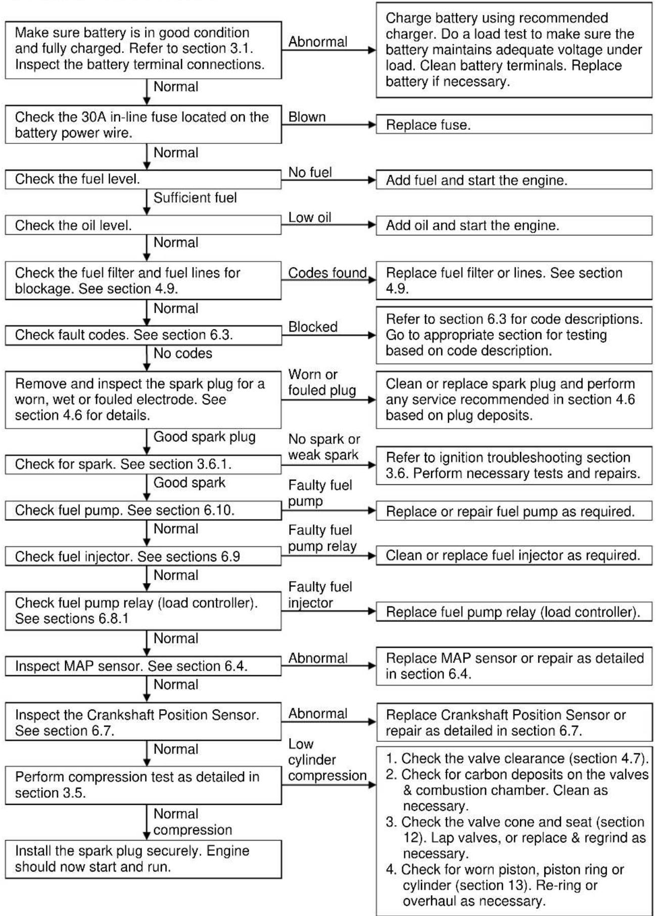
flowchart
graph TD
    A["Make sure battery is in good condition and fully charged. Refer to section 3.1. Inspect the battery terminal connections."] --> B["Abnormal"]
    B --> C["Charge battery using recommended charger. Do a load test to make sure the battery maintains adequate voltage under load. Clean battery terminals. Replace battery if necessary."]
    C --> D["Check the 30A in-line fuse located on the battery power wire."]
    D --> E["Normal"]
    E --> F["Blown"]
    F --> G["Replace fuse."]
    G --> H["Check the fuel level."]
    H --> I["Sufficient fuel"]
    I --> J["No fuel"]
    J --> K["Add fuel and start the engine."]
    K --> L["Check the oil level."]
    L --> M["Low oil"]
    M --> N["Add oil and start the engine."]
    N --> O["Check the fuel filter and fuel lines for blockage. See section 4.9."]
    O --> P["Normal"]
    P --> Q["Codes found"]
    Q --> R["Replace fuel filter or lines. See section 4.9."]
    R --> S["Check fault codes. See section 6.3."]
    S --> T["No codes"]
    T --> U["Blocked"]
    U --> V["Refer to section 6.3 for code descriptions. Go to appropriate section for testing based on code description."]
    V --> W["Worn or fouled plug"]
    W --> X["Clean or replace spark plug and perform any service recommended in section 4.6 based on plug deposits."]
    X --> Y["Remove and inspect the spark plug for a worn, wet or fouled electrode. See section 4.6 for details."]
    Y --> Z["Good spark plug"]
    Z --> AA["No spark or weak spark"]
    AA --> AB["Check for spark. See section 3.6.1."]
    AB --> AC["Faulty fuel pump"]
    AC --> AD["Refer to ignition troubleshooting section 3.6. Perform necessary tests and repairs."]
    Z --> AE["Good spark"]
    AE --> AF["Check fuel pump. See section 6.10."]
    AF --> AG["Faulty fuel pump relay"]
    AG --> AH["Replace or repair fuel pump as required."]
    AF --> AI["Normal"]
    AI --> AJ["Check fuel injector. See sections 6.9"]
    AJ --> AK["Faulty fuel pump relay"]
    AK --> AL["Clean or replace fuel injector as required."]
    AJ --> AM["Normal"]
    AM --> AN["Check fuel pump relay (load controller). See sections 6.8.1"]
    AN --> AO["Faulty fuel injector"]
    AO --> AP["Replace fuel pump relay (load controller)."]
    AN --> AQ["Normal"]
    AQ --> AR["Inspect MAP sensor. See section 6.4."]
    AR --> AS["Abnormal"]
    AS --> AT["Replace MAP sensor or repair as detailed in section 6.4."]
    AU["Inspect the Crankshaft Position Sensor. See section 6.7."] --> AV["Abnormal"]
    AV --> AW["Replace Crankshaft Position Sensor or repair as detailed in section 6.7."]
    AX["Perform compression test as detailed in section 3.5."] --> AY["Low cylinder compression"]
    AZ["Install the spark plug securely. Engine should now start and run."] --> BA["Normal compression"]
    BA --> BB["Check for worn piston, piston ring or cylinder (section 13). Re-ring or overhaul as necessary."]
3.4 Hard Starting (cranks & starts, but is hard to start)

flowchart
graph TD
    A["Make sure battery is in good condition and fully charged. Refer to section 3.1. Inspect the battery terminal connections."] -->|Abnormal| B["Charge battery using recommended charger. Do a load test to make sure the battery maintains adequate voltage under load. Clean battery terminals. Replace battery if necessary."]
    A -->|Normal| C["Check the fuel level."]
    C -->|No fuel| D["Add fuel and start the engine."]
    C -->|Sufficient fuel| E["Check the oil level."]
    E -->|Low oil| F["Add oil and start the engine."]
    E -->|Normal| G["Check fault codes. See section 6.3."]
    G -->|Codes found| H["Refer to section 6.3 for code descriptions. Go to appropriate section for testing based on code description."]
    G -->|No codes| I["Check the fuel filter and fuel lines for blockage. See section 4.9."]
    I -->|Blocked| J["Replace fuel filter or lines. See section 4.9."]
    I -->|Normal| K["Remove and inspect the spark plug for a worn, wet or fouled electrode. See section 4.6 for details."]
    K -->|Worn or fouled plug| L["Clean or replace spark plug and perform any service recommended in section 4.6 based on plug deposits."]
    K -->|Good spark plug| M["No spark or weak spark"]
    M -->|No spark or weak spark| N["Refer to ignition troubleshooting section 3.6. Perform necessary tests and repairs."]
    M -->|Good spark| O["Check fuel pump. See section 6.10."]
    O -->|Faulty fuel Pump| P["Replace or repair fuel pump as required."]
    O -->|Normal| Q["Check fuel pump relay (load controller). See sections 6.8.1"]
    Q -->|Faulty fuel pump relay| R["Replace fuel pump relay (load controller)."]
    Q -->|Normal| S["Check fuel injector. See sections 6.9"]
    S -->|Faulty fuel injector| T["Clean or replace fuel injector as required."]
    S -->|Normal| U["Inspect MAP sensor. See section 6.4"]
    U -->|Abnormal| V["Replace MAP sensor or repair as detailed in section 6.4."]
    U -->|Normal| W["Inspect temperature sensor. See section 6.6."]
    W -->|Abnormal| X["Replace temperature sensor or repair as detailed in section 6.6."]
    W -->|Normal| Y["Perform compression test as detailed in section 3.5."]
    Y -->|Low cylinder compression| Z["Check the valve clearance (section 4.7)."]
    Y -->|Normal compression| AA["Check for carbon deposits on the valves & combustion chamber. Clean as necessary."]
    Y -->|Normal| AB["Check the valve cone and seat (section 12). Lap valves, or replace & regrind as necessary."]
    Y -->|Normal| AC["Check for worn piston, piston ring or cylinder (section 13). Re-ring or overhaul as necessary."]
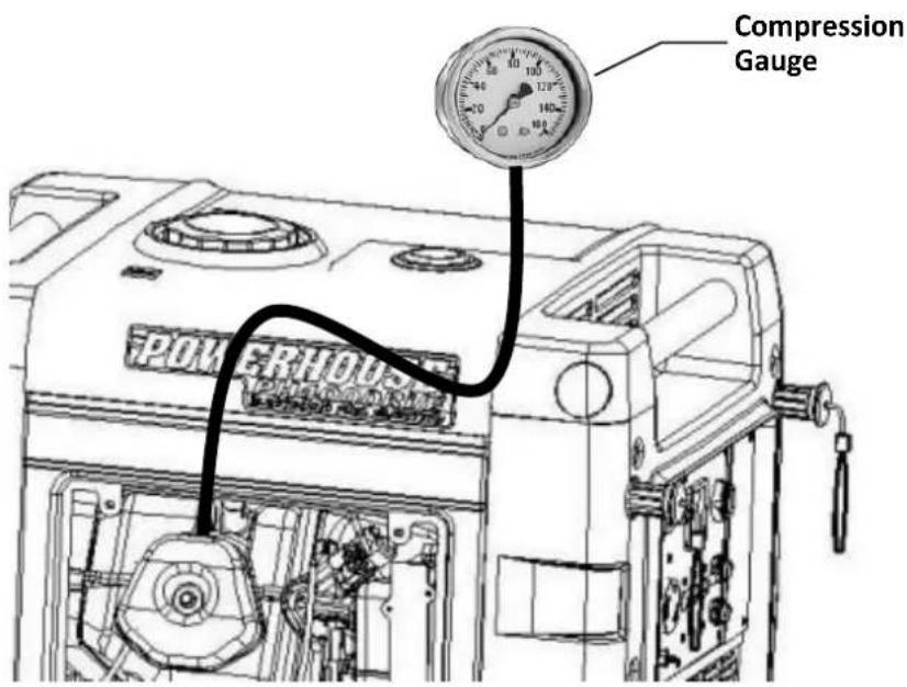
3.5 Cylinder Compression Check

WARNING
For safety, disconnect the 2-pin connector from the side of the fuel injector before cranking the engine during the compression test. Take care when removing the spring clip from this connector, as it is spring loaded and can fly off and be easily lost.
- Remove the spark plug cap and spark plug.
- Install a compression gauge in the spark plug hole.
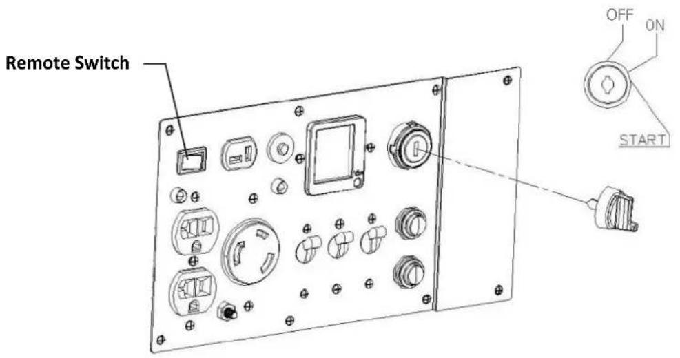
- Push the remote switch to the OFF position.
- Turn the ignition switch to the START position and hold until the compression gauge no longer rises. Read compression.
Cylinder compression 0.45Mpa (65 psi) @ \~800rpm
3.6 Ignition System
This section deals with troubleshooting a faulty ignition system. Before diagnosing an ignition problem, make sure the battery is fully charged and the terminal connections are clean and tight.
This generator is equipped with an EFI system that controls the ignition and requires 10.5VDC to run properly. The battery must have a voltage of at least 10.5VDC while being cranked to be able to start the generator. Thus it is recommended the battery be fully charged before doing any diagnostic work on the generator. Consult section 3.1 for more details.
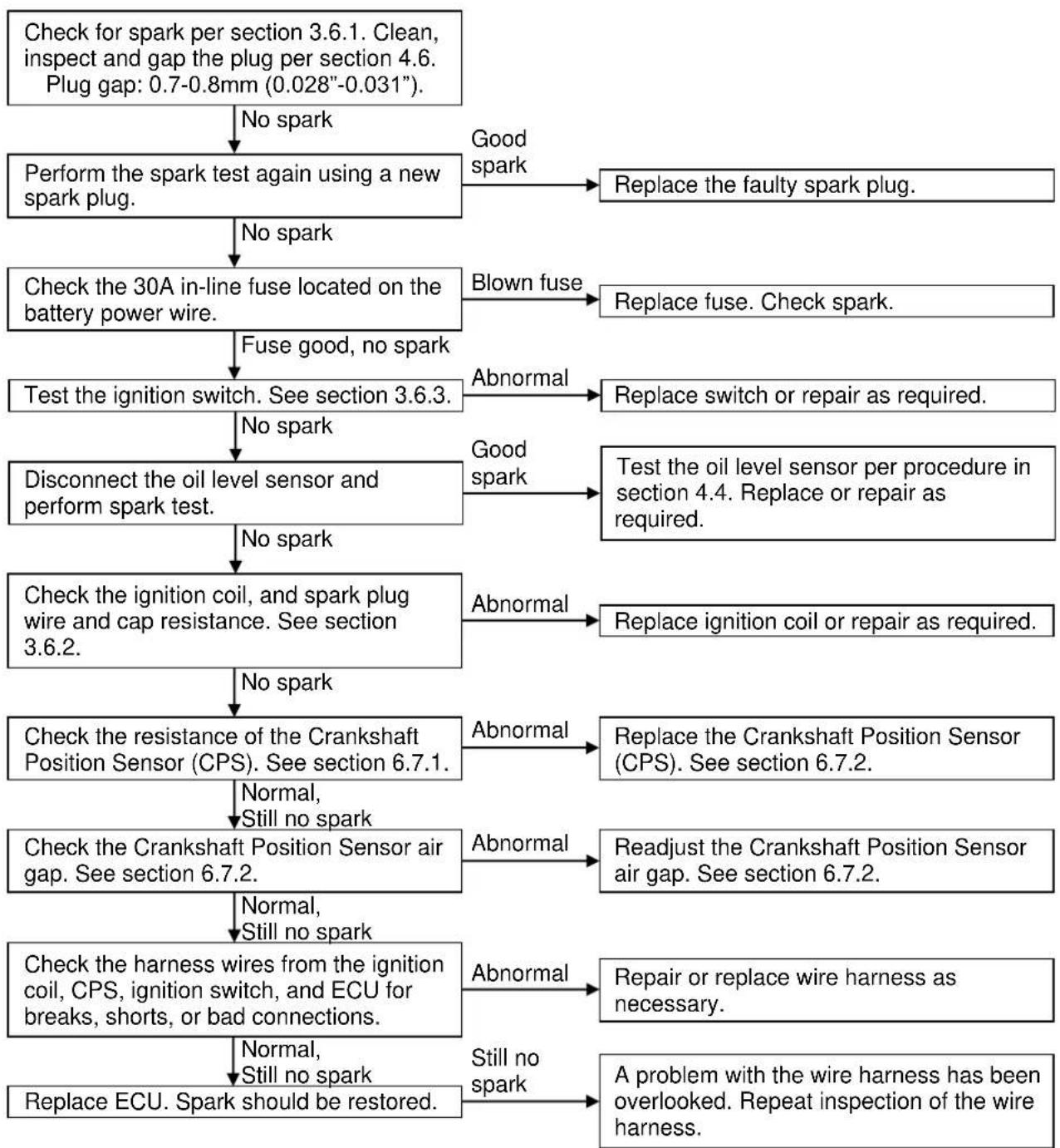
flowchart
graph TD
    A["Check for spark per section 3.6.1. Clean, inspect and gap the plug per section 4.6. Plug gap: 0.7-0.8mm (0.028"-0.031)."] --> B["Perform the spark test again using a new spark plug."]
    B -->|No spark| C["Check the 30A in-line fuse located on the battery power wire."]
    B -->|Good spark| D["Replace the faulty spark plug."]
    B -->|No spark| E["Fuse good, no spark"]
    E --> F["Test the ignition switch. See section 3.6.3."]
    F -->|No spark| G["Disconnect the oil level sensor and perform spark test."]
    F -->|Abnormal| H["Replace fuse. Check spark."]
    F -->|Good spark| I["Test the oil level sensor per procedure in section 4.4. Replace or repair as required."]
    G -->|No spark| J["Check the ignition coil, and spark plug wire and cap resistance. See section 3.6.2."]
    G -->|Abnormal| K["Replace ignition coil or repair as required."]
    J -->|No spark| L["Check the resistance of the Crankshaft Position Sensor (CPS). See section 6.7.1."]
    L -->|Normal, Still no spark| M["Check the Crankshaft Position Sensor air gap. See section 6.7.2."]
    L -->|Abnormal| N["Replace the Crankshaft Position Sensor (CPS). See section 6.7.2."]
    M -->|Normal, Still no spark| O["Check the harness wires from the ignition coil, CPS, ignition switch, and ECU for breaks, shorts, or bad connections."]
    M -->|Abnormal| P["Readjust the Crankshaft Position Sensor air gap. See section 6.7.2."]
    M -->|Still no spark| Q["Replace ECU. Spark should be restored."]
    N -->|Abnormal| R["Repair or replace wire harness as necessary."]
    N -->|Still no spark| S["A problem with the wire harness has been overlooked. Repeat inspection of the wire harness."]
3.6.1 Checking for Spark

WARNING
- Don't pull the recoil starter or turn the ignition switch to "START" while touching the high tension wire (spark plug wire).
- Fill the oil reservoir to the correct operational level. Turn off the remote switch for safety.
- Pull off the spark plug cap and remove the spark plug using a spark plug wrench.
- Inspect the spark plug color and deposits (section 4.6). Clean or replace plug, as necessary before checking spark. Make sure you are using an F7RTC or equivalent spark plug.
- Remove clip and disconnect the power wires from the fuel injector (Fig. 1). Use needle nose pliers when removing the spring clip from this connector, as it is spring loaded and can fly off and be easily lost. Pull the recoil starter several times with the ignition switch OFF to clear unburned gases from the cylinder.
- Install the spark plug into the plug cap.
- Attach a ground wire between the engine block and the negative (-) electrode (the steel body of the spark plug) as shown in Fig. 2.
- Crank the engine over using the ignition key and watch the spark plug gap for signs of spark. A healthy ignition system will produce a spark as shown in Fig. 3.
- If there is no, or a weak, spark; continue following the ignition troubleshooting flowchart.

natural_image
Close-up of a mechanical component being adjusted with a pliers, showing wiring and a red arrow indicating a specific part (no text or symbols visible)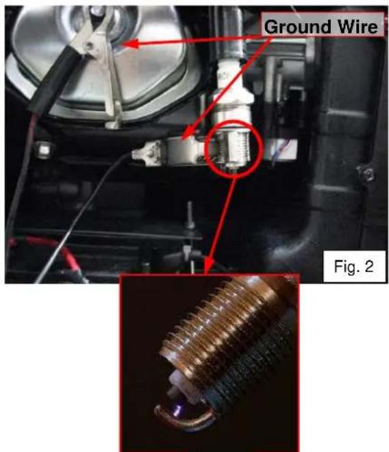
Fig. 3
3.6.2 Ignition Coil Inspection
Before beginning to test the ignition switch, make sure the battery is fully charged and the terminal connections are clean and tight. See section 3.1 for battery charge requirements.
- Remove the control panel and carefully let it hang out of the way. Locate the 2-pin primary coil plug with a red wire with black stripe and blue wire with white stripe and unplug it from the wiring harness (Fig. 4).
- Attach the two leads of the tester to the red wire with black stripe and blue wire with white stripe and measure the primary resistance of the ignition coil. The primary coil resistance should be between 4.0-4.5Ω.
- Check for continuity between the blue wire with white stripe, the red wire with black stripe, the spark wire and either coil mount. There should be no continuity between any of these wires and either coil mount.
- If the primary coil resistance is outside the specified range, or there is continuity found between any of the wires and either coil mount tested in step 3, replace the ignition coil.
Primary resistance
4.0-4.5Ω

-
To check the secondary resistance, attach one lead of the tester to the red wire with black stripe of the primary plug of the ignition coil and the other lead to the spark plug cap. The secondary coil resistance should be between 17.5-19.0Ω.
-
If the resistance is too high, remove the spark plug cap and check it again through the spark plug wire itself. If the resistance is within range through the spark plug wire, but not the wire and cap; replace the spark plug cap.
-
Replace the ignition coil if the resistance is outside of the range shown below.
Secondary resistance
17.5-19.0kΩ
3.6.3 Ignition Switch Inspection
Before beginning to test the ignition switch, make sure the battery is fully charged and the terminal connections are clean and tight. See section 3.1 for battery charge requirements.
-
Remove the 8 control panel screws to gain access to the back side of the ignition switch.
-
Find the 6-pin ignition switch connector behind the control panel as shown Fig. 5. Disconnect it for the first part of the test.
-
In the OFF position there should be continuity (0Ω) between the black and pink wires only.
-
In the ON position there should be continuity (0Ω) between the red and orange wires only.
-
In the START position there should be continuity (0Ω) between the red, orange and blue wires only. If the switch passes steps 3-5 then the ignition switch is good. If the switch did not pass steps 3-5 continue to 6.
-
Reconnect the ignition switch for steps 6-8. Refer to the table below for the ignition wire voltages at the different ignition switch positions. In the OFF position verify that there is battery ground at the black and pink wires and that there is 12V positive battery voltage at the red wire.

natural_image
Close-up of a mechanical component with a highlighted connector (no visible text or symbols)-
Turn the switch to the ON position and verify that there is battery ground at the black wire and no ground at the pink wire. Verify that there is 12V positive battery voltage at the red and orange wires.
-
Turn the switch to the START position and verify that there is battery ground at the black wire and no ground at the pink wire. Verify that there is 12V positive battery voltage at the red, orange and blue wires (the starter should crank as well). If the switch has passed steps 6-8 then the ignition switch and the ignition switch wiring are good. If the switch passed steps 3-5, but failed steps 6-8 then look for a wiring problem in the ignition switch circuits.
Wire Voltage at Different Switch Positions
| Wire Color | Ignition Switch Position | ||
| OFF | ON | START | |
| Black | 0V (Gnd) | 0V (Gnd) | 0V (Gnd) |
| Red | 12 (Batt+) | 12 (Batt+) | 12 (Batt+) |
| Orange | 0V | 12 (Batt+) | 12 (Batt+) |
| Blue | 0V | 0V | 12 (Batt+) |
| Pink | 0V (Gnd) | 0V | 0V |
3.7 Oil level sensor fails to stop engine when oil is low
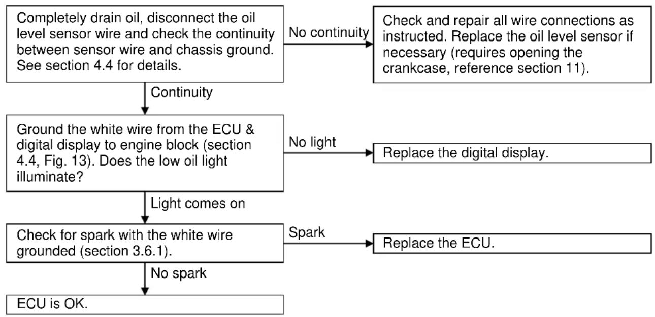
flowchart
graph TD
    A["Completely drain oil, disconnect the oil level sensor wire and check the continuity between sensor wire and chassis ground. See section 4.4 for details."] -->|No continuity| B["Check and repair all wire connections as instructed. Replace the oil level sensor if necessary (requires opening the crankcase, reference section 11)."]
    A -->|Continuity| C["Ground the white wire from the ECU & digital display to engine block (section 4.4, Fig. 13). Does the low oil light illuminate?"]
    C -->|No light| D["Replace the digital display."]
    C -->|Light comes on| E["Check for spark with the white wire grounded (section 3.6.1)."]
    E -->|Spark| F["Replace the ECU."]
    E -->|No spark| G["ECU is OK."]
3.8 Engine stops running

flowchart
graph TD
    A["Does starter crank?"] --> B["Starter cranks"]
    B --> C["Check fuel level."]
    C --> D["Sufficient fuel"]
    D --> E["Check the oil level."]
    E --> F["Sufficient oil"]
    F --> G["Check the 30A in-line fuse located on the battery power wire."]
    G --> H["Fuse good"]
    H --> I["Check fault codes. See section 6.3."]
    I --> J["No codes"]
    J --> K["Check the fuel filter and fuel lines for blockage. See section 4.9."]
    K --> L["Not blocked"]
    L --> M["Remove and inspect the spark plug for a worn, wet or fouled electrode. See section 4.6 for details."]
    M --> N["Good spark plug"]
    N --> O["Check for spark. See section 3.6.1."]
    O --> P["Good spark"]
    P --> Q["Check fuel pump. See section 6.10."]
    Q --> R["Normal"]
    R --> S["Check fuel pump relay (load controller). See sections 6.8.1"]
    S --> T["Normal"]
    T --> U["Check fuel injector. See sections 6.9"]
    U --> V["Normal"]
    V --> W["Inspect MAP sensor. See section 6.4."]
    W --> X["Normal"]
    X --> Y["If the generator will start, but bogs or dies when loaded, inspect the load controller. See section 6.8."]
    Y --> Z["Abnormal"]
    Z --> AA["Perform compression test as detailed in section 3.5."]
    AA --> AB["Abnormal"]

    C --> AC["Low fuel"]
    AC --> AD["Add fuel and restart the engine."]
    D --> AE["Low oil"]
    AE --> AF["Fill oil reservoir to the proper level and restart the engine."]

    G --> AG["Blown"]
    AG --> AH["Replace fuse. Restart engine."]
    H --> AI["Codes found"]
    AI --> AJ["Refer to section 6.3 for code descriptions. Go to appropriate section for testing based on code description."]
    K --> AK["Blocked"]
    AK --> AL["Replace fuel filter or lines. See section 4.9."]

    M --> AM["Worn or fouled plug"]
    AM --> AN["Clean or replace spark plug and perform any service recommended based on plug deposits."]
    N --> AO["Weak spark or no spark"]
    AO --> AP["Refer to ignition troubleshooting section 3.6. Perform necessary tests and repairs."]
    P --> AQ["Faulty fuel pump"]
    AQ --> AR["Replace or repair fuel pump as required."]

    S --> AS["Faulty fuel pump relay"]
    AS --> AT["Replace fuel pump relay (load controller)."]
    T --> AU["Faulty fuel injector"]
    AU --> AV["Clean or replace fuel injector as required."]

    W --> AW["Abnormal"]
    AW --> AX["Replace MAP sensor or repair as detailed in section 6.4."]

    X --> AY["Abnormal"]
    AY --> AZ["Replace the load controller and restart the engine. See section 6.8."]

    style A fill:#f9f,stroke:#333
    style Y fill:#f9f,stroke:#333
3.9 Engine speed can't increase, is unstable or is hunting

flowchart
graph TD
    A["Check the fuel filter and fuel lines for restrictions. See section 4.9."] --> B["Clean"]
    B --> C["Check the air filter element for dirt & restrictions. See section 4.5."]
    C --> D["Clean"]
    D --> E["Inspect spark arrestor for carbon build up. See section 5.1."]
    E --> F["Clean"]
    F --> G["Check fault codes. See section 6.3."]
    G --> H["No codes"]
    H --> I["Remove and inspect the spark plug for a worn, wet or fouled electrode. See section 4.6 for details."]
    I --> J["Good spark plug"]
    J --> K["Check the intake manifold gaskets and vacuum lines for leakage."]
    K --> L["Normal"]
    L --> M["Inspect MAP sensor. See section 6.4."]
    M --> N["Normal"]
    N --> O["Inspect the load controller. See section 6.8."]
    O --> P["Normal"]
    P --> Q["Check fuel pump. See section 6.10."]
    Q --> R["Normal"]
    R --> S["Check fuel pump relay (load controller). See section 6.8.1."]
    S --> T["Normal"]
    T --> U["Check fuel injector. See section 6.9."]
    U --> V["Normal"]
    V --> W["Inspect O₂ sensor. See section 6.5."]
    W --> X["Normal"]
    X --> Y["Inspect the intake manifold and the throttle plate and step motor. See sections 6.11 and 6.12."]
    Y --> Z["Normal"]
    Z --> AA["Perform compression test as detailed in section 3.5."]

    subgraph Sections
        direction TB
        A1["Restricted"] --> A2["Replace fuel filter or lines. See section 4.9."]
        A3["Dirty"] --> A4["Clean the air filter element. See section 4.5."]
        A5["Dirty"] --> A6["Remove and clean carbon deposits. See section 5.1."]
        A7["Codes found"] --> A8["Refer to section 6.3 for code descriptions. Go to appropriate section for testing based on code description."]
        A9["Worn or fouled plug"] --> A10["Clean or replace spark plug and perform any service recommended based on plug deposits."]
        A12["Leaking"] --> A13["Replace vacuum lines and/or intake manifold gaskets as required. See section 6.11."]
        A14["Abnormal"] --> A15["Do output test. Replace MAP sensor or repair as detailed in section 6.4."]
        A17["Faulty fuel pump"] --> A18["Replace the load controller and restart the engine. See section 6.8."]
        A19["Faulty fuel pump relay"] --> A20["Replace or repair fuel pump as required."]
        A22["Faulty fuel injector"] --> A23["Clean or replace fuel injector as required."]
        A25["Abnormal"] --> A26["Do output test. Replace O₂ sensor if necessary. See section 6.5."]
        A27["Abnormal"] --> A28["Replace or repair as required. See sections 6.11 and 6.12."]
        A30["Abnormal"] --> A31["Check for carbon deposits on the valves & combustion chamber. Clean as necessary.<br>Check the valve cone and seat (section 12). Lap valves, or replace & regrind as necessary.<br>Check for worn piston, piston ring or cylinder (section 13). Re-ring or overhaul as necessary.<br>Perform compression test as detailed in section 3.5."]
    end
3.10 Engine speed too high
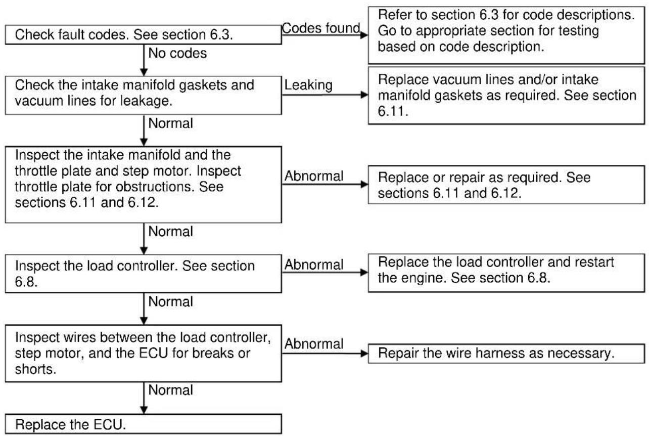
flowchart
graph TD
    A["Check fault codes. See section 6.3."] -->|No codes| B["Check the intake manifold gaskets and vacuum lines for leakage."]
    B -->|Normal| C["Inspect the intake manifold and the throttle plate and step motor. Inspect throttle plate for obstructions. See sections 6.11 and 6.12."]
    C -->|Normal| D["Inspect the load controller. See section 6.8."]
    D -->|Normal| E["Inspect wires between the load controller, step motor, and the ECU for breaks or shorts."]
    E -->|Normal| F["Replace the ECU."]
    A -->|Codes found| G["Refer to section 6.3 for code descriptions. Go to appropriate section for testing based on code description."]
    B -->|Leaking| H["Replace vacuum lines and/or intake manifold gaskets as required. See section 6.11."]
    C -->|Abnormal| I["Replace or repair as required. See sections 6.11 and 6.12."]
    D -->|Abnormal| J["Replace the load controller and restart the engine. See section 6.8."]
    E -->|Abnormal| K["Repair the wire harness as necessary."]
3.10.1 Engine Overspeed Protection
This generator has been designed to prevent the engine from “overspeed” revving. Overspeed revving occurs when a generator’s on-board monitoring systems detect a drop in voltage from the inverter, and the generator attempts to compensate by revving the engine higher to generate more electricity. In the rare event of an inverter failure, there will be no voltage output from the inverter, and the engine will remain revving at or close to its top speed. Overspeed revving for a prolonged period can damage internal components due to increased heat from the engine. With an inverter failure, each of the following three symptoms will be present:
■ The ECU will draw the engine down to idling speed.
■ The digital display will indicate zero (0) Volts.
■ The 120 V receptacles will not supply voltage, regardless of breaker settings.
Verify inverter failure (section 3.11) and replace inverter (section 10.1).
3.11 No or Low AC Output

flowchart
graph TD
    A["Does digital display indicate overload? (It will show "OVER" in the power field and display 000.0V and 00.0A)"] -->|No| B["Check all circuit breakers. Are any of them tripped?"]
    B -->|Not tripped| C["Stop the engine and check the AC receptacles for burnt out contacts and loose or burnt connections."]
    C -->|Normal| D["Check to see if the engine feels jammed or seized upon being shut down. There could be magnets that have broken free from the rotor. Inspect the rotor. See section 10."]
    D -->|Engine turns normally| E["Measure the stator output voltage while running (see section 3.12), and the stator winding resistance (see section 10.1)."]
    E -->|Normal| F["Replace inverter. See section 10.1."]
    A -->|Yes| G["Disconnect the load and press the overload reset button. If the inverter fails to reset refer to section 6.8.2."]
    B -->|Tripped| H["Disconnect the load and reset breakers."]
    C -->|Abnormal| I["Replace the AC receptacles if necessary."]
    D -->|Engine jammed| J["Inspect the rotor magnets for damage, replace the rotor if damaged. See section 10."]
    E -->|Abnormal| K["Inspect and repair stator wire harness or replace stator. See section 10.1."]
3.12 Measuring stator output voltage while running

- Unplug the connector from the inverter and start the engine (Fig. 6), check voltage between pins 1 & 4, between pins 2 & 4 and between pins 1 & 2 (Fig. 8). Note, the engine will be running at a high RPM.
- There should be approximately 180-300VAC at each test with the engine running at high speed. If one or more of the three tests fail, the problem is either a damaged wire harness or a defective stator/rotor assembly. If the wire harness is the problem, look for and repair the damage.
- If the stator/rotor assembly is the problem, the stator will need to be replaced. If all three tests are OK, the problem is probably the inverter.
3.13 No DC output at battery charge receptacle
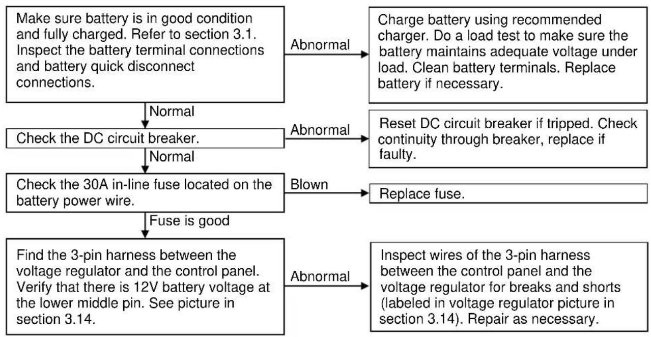
flowchart
graph TD
    A["Make sure battery is in good condition and fully charged. Refer to section 3.1. Inspect the battery terminal connections and battery quick disconnect connections."] -->|Abnormal| B["Charge battery using recommended charger. Do a load test to make sure the battery maintains adequate voltage under load. Clean battery terminals. Replace battery if necessary."]
    A -->|Normal| C["Check the DC circuit breaker."]
    C -->|Abnormal| D["Reset DC circuit breaker if tripped. Check continuity through breaker, replace if faulty."]
    C -->|Normal| E["Check the 30A in-line fuse located on the battery power wire."]
    E -->|Blown| F["Replace fuse."]
    E -->|Fuse is good| G["Find the 3-pin harness between the voltage regulator and the control panel. Verify that there is 12V battery voltage at the lower middle pin. See picture in section 3.14."]
    G -->|Abnormal| H["Inspect wires of the 3-pin harness between the control panel and the voltage regulator for breaks and shorts (labeled in voltage regulator picture in section 3.14). Repair as necessary."]
3.14 Battery will not charge

flowchart
graph TD
    A["Before troubleshooting, inspect battery condition (refer to section 3.1). Inspect the battery terminal & quick disconnect connections."] -->|Abnormal| B["Charge battery using recommended charger. Do a load test to make sure the battery maintains adequate voltage under load. Clean battery terminals. Replace battery if necessary."]
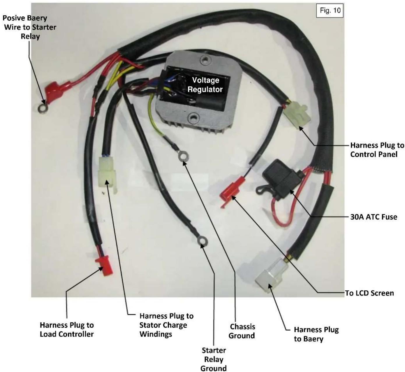
    A -->|Normal| C["Check the DC voltage at the battery and the control panel with the generator running. See steps 1 and 2 on the following page."]
    C -->|Abnormal| D["Check all wire connections of the voltage regulator. See the picture on the following page."]
    C -->|Normal| E["Unplug the stator charge windings from the voltage regulator and measure the voltage of the stator charge windings (Fig. 9). Voltage: 16-20VAC"]
    E -->|Abnormal| F["Check the wiring harness for breaks or shorts, repair as necessary. If no wiring issues found, replace the stator. See section 10."]
    E -->|Normal| G["Replace the voltage regulator."]

- Battery charge voltage from the voltage regulator at the starter battery should be 12.0 to 14.5 volt DC battery charge.
- The voltage to the control panel should measure 13 to 15 volts DC.
3.15 Engine will not start or stop with remote.

In order for the remote to be fully functional the ignition key MUST be in the OFF position and remain in the OFF position while the remote switch is turned on. If the generator is started with the key, whether the remote switch is on or off, the remote will not work properly. If the key is turned to the ON position, before or after the remote switch is turned on, the remote will not work properly. Before beginning inspection of the remote system, make sure that the ignition switch being on is not the cause of the problem. If so, turn the ignition key to the OFF position and cycle the remote switch off and on again to resume normal remote operation.

flowchart
graph TD
    A["Does the red indicator light on the remote fob come on, when either the start or stop buttons are pushed?"] -->|Yes| B["Inspect the remote switch and load controller (see section 3.15.1)."]
    A -->|No| C["Replace the remote fob battery."]
    B -->|Normal| D["Check 6-pin connection at the remote receiver for dirty or damaged connections, and broken or shorted wires."]
    B -->|Abnormal| E["Repair wiring or replace rocker switch or load controller as necessary."]
    D -->|Abnormal| F["Repair or replace faulty connections. Repair any broken or shorted wires."]
    D -->|Normal| G["Replace the remote transmitters and receiver."]
■ The remote transmitter and receiver are a matched set, and are bought in pairs. They cannot be retrained.
3.15.1 Remote Switch Inspection
If the remote system is suspected to be faulty, test the remote switch using the following procedure.
- Remove the 8 control panel screws and gently pull out the control panel to gain access to the remote switch.
- Make a note of the remote switch wire locations and disconnect the wires from the back of the switch.
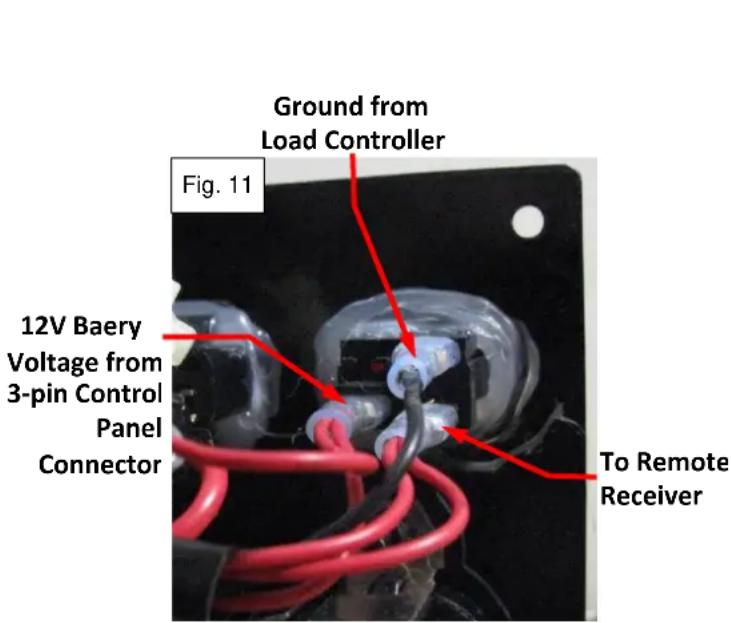
- Put the ohmmeter test leads on the switch terminals marked 12V Battery Voltage and To Remote Receiver (see Fig. 11). In the ON position there should be continuity between these terminals. In the OFF position there should be no continuity. Replace the switch if this is not the case.
- Put the ohmmeter test leads on the switch terminals marked 12V Battery Voltage and Ground from Load Controller (see Fig. 11). In the ON position there should be 50-60Ω between these terminals through the incandescent bulb of the switch. If there is no resistance it indicates there is a short, if there is an open circuit then the bulb is burnt out; in either case replace the switch. In the OFF position there should be no continuity. Replace the switch if this is not the case.
- After verifying or replacing the switch, continue the test.
- Check if there is 12V battery voltage present on the wire from the 3-pin control panel connector. Repair any breaks or shorts to restore 12V battery power as necessary. Reconnect the wire to the lower left terminal of the switch as shown below.
- Check continuity on the wire from the remote switch to the remote receiver. Repair any breaks or shorts as necessary. Reconnect the wire to the lower right terminal of the switch as shown below.
- Check that there is good ground on the wire marked Ground from Load Controller (see Fig. 11). If not, check this wire's continuity between the remote switch and the load controller. Repair any breaks or shorts as necessary. If the continuity is good, but the load controller is not supplying ground, then replace the load controller (see section 6.8). Having verified or restored ground to this wire, reconnect it to the upper terminal of remote switch shown below.
- Turn the remote switch on and verify that the light inside the switch illuminates (see Fig. 12). The light should flash on and off, approximately 0.5 second on and 2.0 seconds off. If the light does not illuminate, or does not flash on and off, replace the load controller (see section 6.8).

4. Maintenance
4.1 Maintenance schedule
| Item | Maintenance Procedure | Regular Service period. Perform at every indicated month or operating hour interval, whichever occurs first. | ||||
| Each Use | First Month Or 20 HRS | Every 3 Months or 50 HRS | Every 6 Months Or 100 HRS | Every Year Or 300 HRS | ||
| Engine Oil | Check | ○ | ||||
| Change | ○ | ○ | ||||
| Air cleaner | Check | ○ | ||||
| Clean | O_(1) | |||||
| Spark Plug | Clean - adjust | ○ | ||||
| Spark Arrester | Clean | ○ | ||||
| Fuel Filter | Check | ○ | ||||
| Replace | O_(2) | |||||
| Valve clearance | Check - adjust | O_(3) | ||||
| Fuel tank & strainer | Clean | O_(2) | ||||
| Fuel line | Check | Every 2-years (Replace as necessary) | ||||
| Battery | Clean – charge | Charge monthly during long term storageCheck terminals for corrosion monthly, clean as needed.Expected battery life is 2 years, but can be affected by operating environment. | ||||
Notes:
(1) Service more frequently when operating in dusty areas, every 10 hours or every day.
(2) Service more frequently under extreme cold or hot weather, and dusty conditions. Replace filter and clean tank and strainer immediately after any cases of fuel contamination.
(3) Service should be performed by a POWERHOUSE® authorized agency, unless correct tools and a professional specialist are available. Service should always be performed according to the Service Manual.
4.2 Checking the oil level
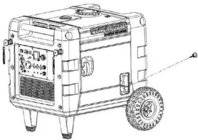
Stop the engine, be sure to put the generator on a flat surface when checking.
- Loosen the screw on the engine oil access cover and remove the cover.
- Remove the oil dipstick and check the oil level.
- If the oil level is low, add oil until it reaches the edge of the upper line on the dipstick (when screwed in as shown in the picture below).
- Re-install the dipstick and the engine oil access door before restarting your generator.
natural_image
Line drawing of a portable gas generator with wheels and control panel (no text or symbols)
4.3 Changing oil
Drain the oil while the engine is still warm to assure rapid and complete draining.

CAUTION
■ Make sure to turn the engine switch before draining.
- Loosen the screw on the engine oil access cover and remove the cover.
- Remove the dipstick.
- Install the oil drain pipe.
- Drain dirty oil into a container. Allow enough time for the oil to drain completely.
- Refill with the recommended oil and check the oil level. Check to be sure the oil level is at the upper line on the dipstick (with dipstick screwed in).
- Reinstall the dipstick.
- Reinstall the access cover and tighten the screw securely.
Engine oil capacity: 33.8 oz. (1.0L)


NOTE
■ Please dispose of used motor oil in a manner that is compatible with the environmental and local disposal regulations. Do not throw it in the trash or pour it on the ground.
4.4 Checking the Oil Level Sensor
-
Remove the maintenance cover and locate the oil level sensor lead which is between the battery and the side panel.
-
Disconnect the oil level sensor while the engine is running.
-
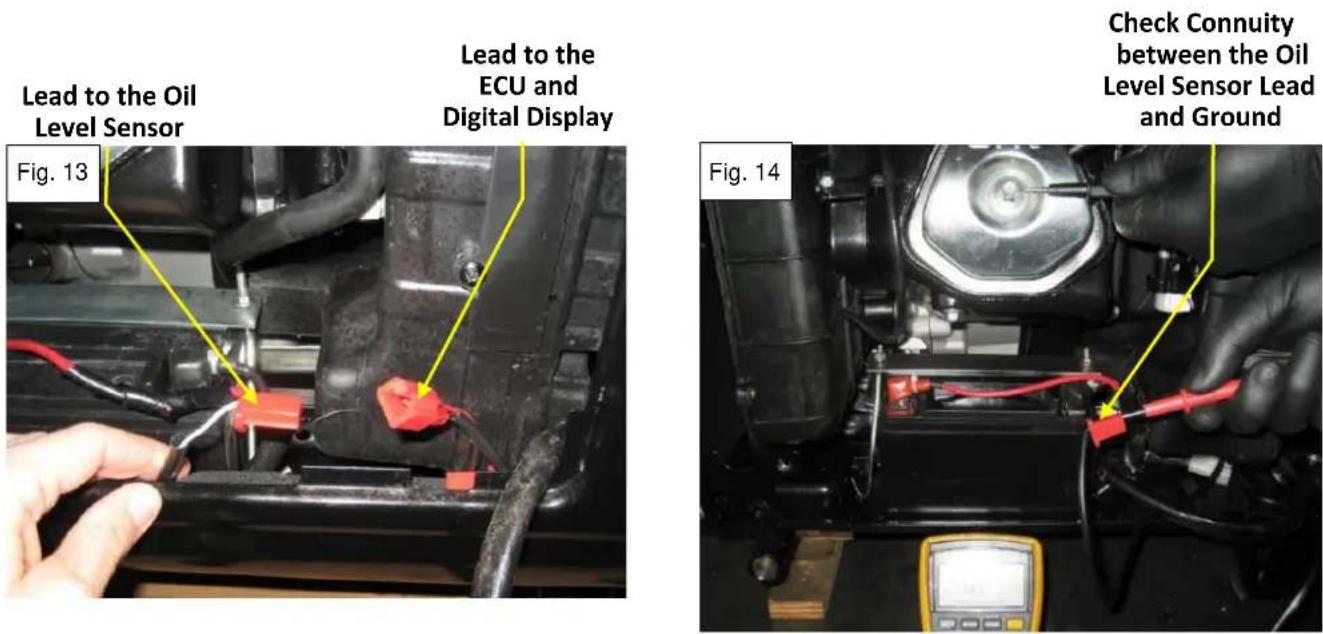
Ground the lead from the ECU and digital display (this lead shown below in Fig. 13) to the engine block, to verify that the engine will stop and that the low oil light is lit.
-
If the engine does not stop, then trace the lead all the way back to pin 8 of the ECU connector, looking for breaks or shorts (refer to wiring diagram, and section 6.2). Repair as necessary and retest. If there are no wiring issues and the engine does not stop when this wire is grounded then replace the ECU.
-
If the low oil light on the digital display does not illuminate when the oil level sensor lead is grounded, then trace the lead all the way back to the white wire coming from the digital display, looking for breaks or shorts (refer to wiring diagram, and section 7). Repair as necessary and retest. If there are no wiring issues and the low oil light does not illuminate when this wire is grounded then replace the digital display.
-
After confirming that the engine oil is at the proper level, test for continuity between the terminal of the oil level sensor lead and the engine block. No continuity indicates a normal condition.
-
Drain the oil and check continuity again. Continuity between the oil level sensor lead (shown in Fig. 13) and engine block (Fig. 14) when the oil is drained from the engine indicates a normal condition. No continuity after the oil has been drained would indicate a faulty oil level sensor or a damaged wire that must be repaired or replaced.
-
If the oil level sensor passes steps 6 and 7 then it is good. If it does not it will need to be replaced. Replacing the oil sensor requires dissembling the engine and opening up the crankcase (see the engine exploded view in section 11 for reference).

- Failure to replace a faulty oil level sensor can lead to permanent engine damage or destruction if the engine runs low on oil.
4.5 Air Cleaner
Inspection and cleaning:
- Loosen the panel screws and remove the side maintenance cover.
- Remove the four cartridge retaining screws.
- Remove the filter cartridge and the filter element.
- If filter element and the filter case are soaked with excessive engine oil this could be a sign of excessive blow-by or a defective PCV valve. Pull the spark plug to check for signs of oil burning or fouling (section 4.6 for details). If the plug looks normal but the PCV hose is full of oil, replace the PCV valve (must replace the whole valve cover).
- Wash the element in a non-flammable or high flash point solvent and dry them thoroughly.
- Soak the element in clean engine oil and squeeze out the excess oil.
- Reinstall the filter element and the air filter cartridge. Tighten the four cartridge screws securely.
- Reinstall the maintenance cover and tighten the screws securely.

CAUTION
A dirty air cleaner will restrict air flow to the engine, reducing engine performance. If the engine is operated in dusty areas, clean the air cleaner more often than specified in the Maintenance Schedule (section 4.1).
■ Never run the engine if there is no element or if the filter is damaged, as it will cause serious damage to the engine.
4.6 Spark plug
Inspection and cleaning:
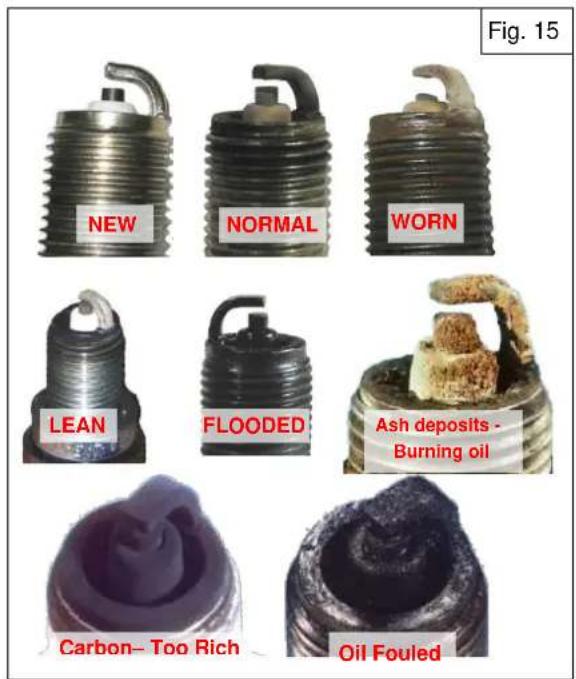
- Remove the spark plug using a plug wrench and carefully inspect it. Compare the color and deposits on the plug to Fig. 15. It should look normal or worn if it is time for replacement. Evidence of lean, rich or flooded conditions indicate the EFI system is in need of service (section 6). Ash deposits are evidence of oil burning under normal combustion conditions and usually show up toward the end of the engine's service life; more frequent plug replacement will be required. Oil fouling is evidence of far too much oil entering the cylinder, usually engine repair will be required to fix the problem (sections 11, 12 & 13). Oil burning can also be caused by a faulty PCV valve (built into the valve cover). This will cause large amounts of engine oil to get pulled through the PCV hose, collect in the air cleaner, and get sucked into the throttle body. If this is the case, try replacing the PCV valve (valve cover).
- Remove carbon or other deposits with a plug cleaner or stiff wire brush. Check the sealing washer for damage.

natural_image
Technical line drawing of a mechanical component with threaded shaft and flange (no text or symbols)| Spark Plug Type | F7RTC |
- Measure the plug resistance; replace the spark plug if the resistance is outside of these values.

natural_image
Technical diagram of a mechanical connector with a magnified inset showing internal components (no text or symbols)| Spark Plug Resistance | 3 - 9 kΩ |
- Measure the plug gap with a wire-type feeler gauge. Adjust by bending the side electrode if the measurement is not within the specified tolerance.

natural_image
Technical line drawing of a mechanical component with threaded shaft and threaded base (no text or symbols)| Spark Plug Gap | 0.028" - 0.031" (0.7 - 0.8mm) |
- Install the plug finger tight to seat the washer and then tighten with a plug wrench. Torque value shown below; or 18 of a turn after seating with a previously compressed washer, or 14 turn after seating with a new uncompressed washer.
Torque valve is 8.0-10 ft-lbs. (11-13 Nm)
37 PH4000Ri/E SM Revision 12-31-2014
4.7 Valve clearance

- Valve clearance inspection and adjustment must be performed with the engine cold.
Inspection and adjustment:
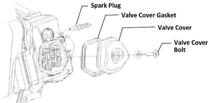
- Remove spark plug, valve cover bolt, valve cover and valve cover gasket.
-
Rotate the engine in a clockwise direction until the piston is at top dead center (TDC) and the intake and exhaust valves are closed.
-
Insert a feeler gauge between the rocker arm and the valve and measure the valve clearance.
| Valve clearance | Intake | 0.10 ± 0.02mm (0.004" ±0.001") |
| Exhaust | 0.15 ± 0.02mm (0.006" ±0.001") |
- If adjustment is necessary, proceed as follows.
a. Secure the rocker arm adjustment nut and loosen the jam nut.
b. Adjust the rocker arm nut until the desired valve clearance is attained.
c. Secure the rocker arm nut and tighten the jam nut. Recheck the clearance.
- Clean the cylinder block and valve cover.
- Replace the rubber valve cover seal.
- Install the removed parts in the reverse order of removal.

natural_image
Close-up of a mechanical component being adjusted with a tool, showing internal gears and shafts (no text or symbols visible)4.8 Evaporation Control System
The evaporative control system is shown in the line drawing below. The 380cc carbon canister must be present and connected as shown to meet CARB evaporative emission standards. Also note that this generator has an electronic fuel pump that is providing pressurized fuel to the fuel injector. This requires a higher grade of fuel hose that can easily handle the higher pressures of a fuel injection system and is less permeable to meet the CARB emission standard (SAE 30R9 hose). This generator comes equipped with fuel hoses of this grade and they are considered as part of the evaporative control system. Use the OEM replacement hose, if possible. This grade of fuel hose is commonly available at auto part stores as “fuel injection hose”, if the OEM replacement hose is unavailable.

4.9 Fuel Filter
WARNING
■ Wait 5-10 seconds after engine shutdown prior to filter change to allow the fuel pressure to bleed off. Use only the OEM Powerhouse replacement fuel filter when servicing this generator.
Replacing Fuel Filter:
- Remove the 8 control panel screws and carefully allow the control panel to hang out of the way.
- Remove hose clamps and remove fuel filter.
- Replace in reverse order of disassembly. Take care not to introduce any debris or contaminants in the fuel system during this process. Contaminants introduced here will cause irreparable fuel injector damage.
natural_image
Interior view of an electronic device showing wiring and components, with a red circle highlighting a specific component (no visible text or symbols)
natural_image
Close-up of an automotive engine bay with orange and black wiring, no visible text or symbols5. Muffler system
5.1 Spark arrestor

If the generator has been running, the muffler will be very hot. Allow it to cool before proceeding.
The spark arrester must be serviced every 100 hours to maintain its efficiency. A clogged spark arrestor will partially plug the exhaust system causing a substantial loss in power and performance.
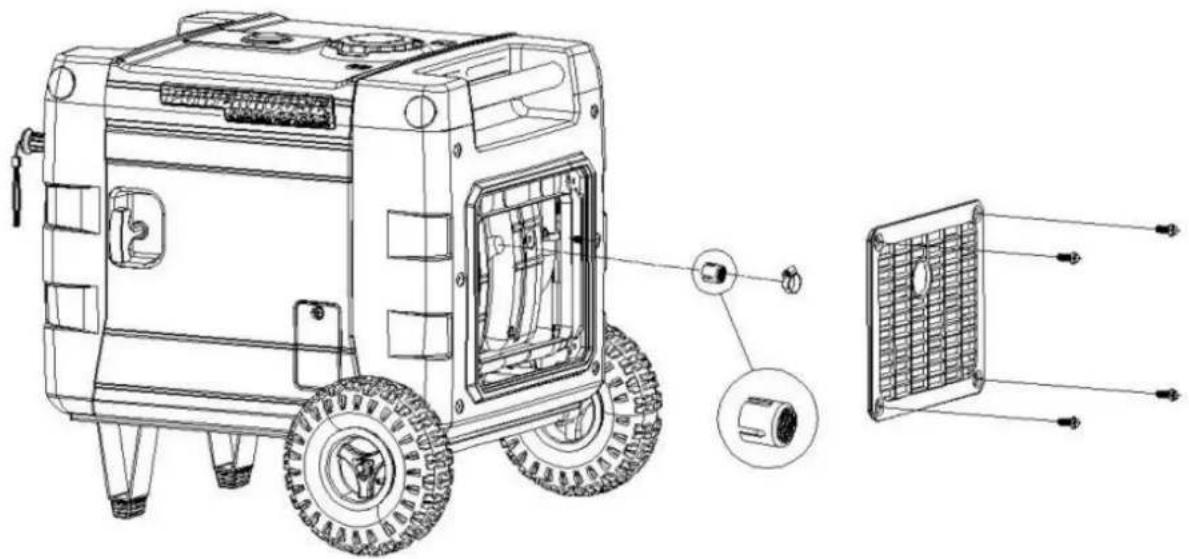
- Remove the exhaust grill to access the spark arrestor.
- Remove the clamp holding the spark arrester to the muffler.
- Remove the spark arrester.
- Clean the spark arrestor with a stiff wire brush.
- Replace the spark arrestor if the wire mesh is perforated or torn.
- Reinstall the spark arrester.
- Reinstall the exhaust grill.
natural_image
Technical line drawing of a portable gas stove with labeled components (no text or symbols present)5.2 Muffler Removal

CAUTION
■ Muffler removal and installation must be performed with the engine cold.
- Drain all gasoline from the fuel tank before disassembly.
- Keep the unit away from all heat, flame and sparks.
Disassembly and reassembly
- Disconnect battery.
- Remove the front and rear end panel, the side panels, and the top cover (reference the Outer Generator Housing exploded view in section 8.1).
- Remove upper frame, with fuel tank, as one assembly (Fig. 19-A).
- Remove the muffler cover bolts and remove the muffler cover (Fig. 19-B).
- Remove the muffler bolts. Carefully note the placement of the various length bolts and spacers during removal and reassembly (Fig. 19-C).
- Remove the muffler. This gains access to O_2 sensor and exhaust fan (Fig. 19-D).
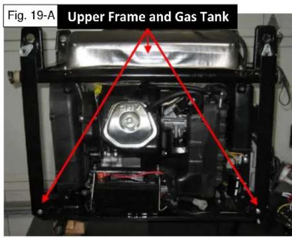
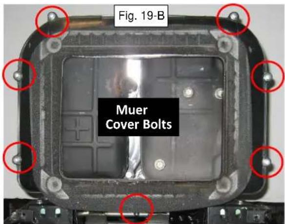


6. Electronic Fuel Injection (EFI)
This generator is equipped with an Electronic Fuel Injection (EFI) system. An on-board computer, referred to in this manual as an ECU (Engine Control Unit) utilizes a series of virtual maps (lookup tables) that provide values for various aspects of engine performance. The ECU analyzes data provided through the various engine sensors to determine the best combination of values from these lookup tables to provide optimum performance and minimize emissions. This is communicated to the generator components through the use of digital signals. This is in contrast to non-computer-controlled ignition systems that rely on mechanical feedback, and sometimes vacuum, to control the motion of the various components.
6.1 Overview of EFI System
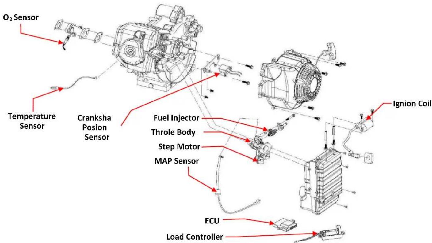
The ECU collects and processes data from a group of sensors that monitor various engine and inverter conditions. It uses that information to meter the fuel, adjust the ignition timing and control the throttle of the engine. Fault codes are generated by the ECU whenever it detects a malfunction of an EFI system sensor or component. The components of the EFI system are shown in the diagram below. Their functions, maintenance and service are detailed in the sections that follow.
6.2 Engine Control Unit (ECU)
The ECU is the computer that controls the EFI system. It has on-board diagnostics that will store and display fault codes if it detects problems with the other components of the EFI system. The fault codes will be discussed in section 6.3 to follow. The ECU is solid state and very reliable, and is only replaced after all other diagnostic possibilities have been eliminated. All the other sensors and EFI components and the wires from the ECU to each of the EFI components should be checked first, for shorts or high resistances before concluding the ECU is at fault. Refer to the wiring diagram in section 1.3 when verifying the status of these wires. The ECU connector pinout is shown in the upper left corner of the wiring diagram.
Removal and installation of ECU
- Remove control panel screws and carefully allow the control panel to hang out of the way (see section 7).
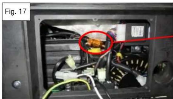
- The ECU is located in the upper right hand corner of the space behind the control panel (Fig. 20). Remove the two ECU mounting screws.
- Disconnect the 18-pin connector and remove the ECU.
- Install in reverse order of removal.

natural_image
Interior view of a vehicle's front panel showing internal components and wiring, with a red circle highlighting a specific component (no text or symbols visible)6.3 Fault Codes
6.3.1 Reading Fault Codes
The fault codes are read using the digital display on the control panel (see below). If the ECU has stored fault codes the Low Oil Indicator (shown below) will blink steadily whenever the key is in the on position. If the generator is truly low on oil, this light will illuminate steadily, but not blink.
It should be noted that if a fault condition is suspected but the Low Oil Indicator is not illuminated, go ahead and follow the procedure for reading the fault codes. Fault code (0650) might be present which indicates that there is a problem with the Low Oil Indicator itself. The Low Oil Indicator is an integral part of the digital display and the entire digital display will need to be replaced to fix the problem.
- If the Low Oil Indicator blinks repeatedly, press the Fault Code Reset Button on the top right of the digital display (see below).
- The display will cycle through the fault codes in the Wattage (P) data field of the digital display. Record all the fault codes.
- Conduct the diagnostic procedures suggested for each fault code and any repairs necessary.
- Erase the fault codes and restart the unit to see if they reappear and if further diagnosis or repair is needed. Fault codes are erased by holding the Fault Code Reset Button down for 10 seconds or more while the key is in the on position. The key must then be turned off to complete the process.
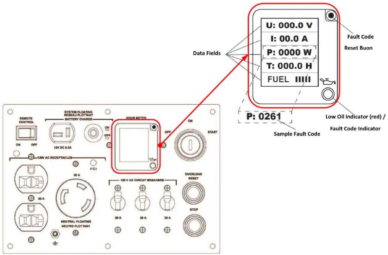
6.3.2 Fault Code Definition and Descriptions
When the generator is running the ECU is constantly monitoring sensors and sending signals to the different components of the EFI system. When it detects a problem with one of these devices it stores a fault code in its memory that can be retrieved for diagnostic purposes. It uses standard OBD II codes and they are shown in the following table along with the descriptions of the conditions producing the code. If a fault code is produced inspect for the condition described below and inspect the respective sensor as described in that sensor's subsection. Retrieving the fault codes is discussed in section 6.3.1.
| EFI System Device | OBD II Fault Code (DTC) | OBD II Fault Description | Description of Condition Producing the Fault |
| Fuel Injector | P0261 | Cylinder 1 Injector Circuit Low | Signal line short to ground |
| P0262 | Cylinder 1 Injector Circuit High | Signal line short to battery voltageSignal line break | |
| MAP Sensor | P0107 | MAP Circuit Low Input | Signal line short to groundSignal line break |
| P0108 | MAP Circuit High Input | Signal line short to battery voltageGround line break | |
| O_2 Sensor | P0130 | O_2 Sensor Circuit Malfunction | Signal line break |
| P0131 | O_2 Sensor Circuit Low Voltage | Signal line short to ground | |
| P0132 | O_2 Sensor Circuit High Voltage | Signal line short to battery voltage | |
| Fuel Pump Relay | P0230 | Fuel Pump Primary Circuit Malfunction | Signal line short to battery voltageSignal line short to groundSignal line break |
| Engine Temperature Sensor | P0117 | Engine Coolant Temperature Circuit Low Input | Signal line short to ground |
| P0118 | Engine Coolant Temperature Circuit High Input | Signal line short to battery voltageSignal line break | |
| Step Motor | P0505 | Idle Control System Malfunction | Signal line short to battery voltageSignal line short to groundSignal line break |
| Fault Code Indicator Light | P0650 | FCI Control Circuit Malfunction | Signal line short to battery voltageSignal line short to groundSignal line break |
6.4 Manifold Air Pressure Sensor (MAP)
The MAP sensor (Fig. 21) is a pressure transducer that translates the current manifold air pressure into a voltage signal to the ECU. It is installed on a vacuum line coming from the throttle body isolator block. The pinout for the MAP sensor connector is shown in the table below.
MAP Sensor Pinout
| Green | 0-5VDC signal to ECU |
| Red | 5VDC input from ECU |
| Black | Ground |
The MAP sensor is one of the key sensors required by the ECU to keep the engine running properly. If this sensor is not working the engine will either die, when loads are put on it, or not run at all. If the ECU has produced the fault codes (0107) or (0108), or you have reason to suspect the MAP sensor is malfunctioning, perform the test detailed below. Before beginning the test, make sure the generator battery is fully charged. Also, inspect the MAP sensor vacuum line for restrictions, leaks, and deterioration; replace if necessary.
6.4.1 MAP Voltage Output Test
- Remove the maintenance cover and remove the 8 control panel screws and carefully allow the control panel to hang out of the way.
-
Remove the vacuum line from the end of the MAP sensor and connect it to a hand operated vacuum pump equipped with a pressure gauge similar to the one shown.
-
Turn the ignition key to the on position.
-
Check the input voltage. Locate the 3 wire MAP sensor connector, but do not disconnect it. Test the voltage between the black and red MAP sensor wires. It should be 4.9-5.1VDC. If it is not in this range inspect the wire harness back to the ECU for breaks or shorts. If no wiring fault is found, verify the MAP input voltage at the ECU. If the MAP sensor input voltage is not 4.9-5.1VDC at the ECU then the ECU is at fault and needs to be replaced.
-
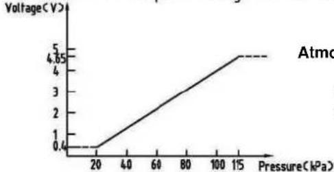
Check the signal voltage (MAP sensor still connected to harness, key is still on). Check the voltage between the black and green MAP sensor wires. At atmospheric pressure the voltage should be approximately 4.0-4.1V, and will vary with barometric pressure and altitude. Slowly pump the vacuum pump connected to the MAP sensor in step 2. The voltage should fall gradually. The voltage vs. pressure graph is shown below. Pressure is shown in kPa (kilopascals), and conversions to psi and in-Hg are given for reference. When the gauge on the vacuum pump shows 10in-Hg, it should read about 2.5VDC, at 20in-Hg it should read about 1VDC. If it is reading no voltage, or the voltage fails to change, or it is getting readings that are grossly off, then the MAP sensor needs to be replaced.
.Operating temperature range: -40°C\~125°C, Operating voltage: 5V±0.1V
Pressure range: 20kPa\~115kPa;
.Pressure and output voltage reference table;
line
| Pressure (kPa) | Voltage (V) | | -------------- | ----------- | | 20 | 0.4 | | 115 | 4.85 |Atmospheric Pressure = 101.3kPa, 14.7psi, or 0.0 in-Hg vacuum
1 psi = 6.9kPa
1 in-Hg = 3.4kPa

6.5 Oxygen Sensor ( O_2 )
The O_2 sensor sends a voltage signal to the ECU that varies with the amount of O_2 in the engine exhaust. The ECU uses this signal to check that the correct amount of fuel is being metered through the fuel injector to maintain the best fuel/air ratio for maximizing the performance and minimizing the emissions. The ECU uses the other sensors to determine how much fuel to provide and the O_2 sensor is providing feedback to the ECU on whether or not the fuel mixture is correct. This is the normal mode of operation and it is called running in a “closed loop”. If the O_2 sensor is not working or the signal is not reaching the ECU; the ECU will continue to run the engine based on input from the other sensors and data stored in look up tables, but it will have no feedback from the Q sensor. It will have no way to verify that the fuel mixture is correct; this is called running in an “open loop”. If the ECU is running in continuous “open loop” it will generate one or more of the following fault codes; (0130), (0131) or (0132). In this case, the cause of the faulty signal or lack of signal from the O_2 sensor will need to be determined. The following information and testing procedure will help determine if a new O_2 sensor is needed.
The voltage signal varies from 0.1-1.0VDC as the ratio of the percentage of O_2 between the ambient air and exhaust air changes. As the percentage of O_2 in the exhaust air approaches zero (the fuel mixture gets richer) the voltage signal approaches 1.0VDC. When the percentage of O_2 in the exhaust air gets closer to ambient air (the fuel mixture gets leaner) the voltage signal drops closer to 0.1VDC. The procedures for testing the O_2 sensor are detailed below.
It should also be noted that during periods of changing loads, or when the generator is running at maximum capacity, the ECU is not using the O_2 sensor signal to run the engine. If the engine has poor performance under these conditions then the cause is probably not the O_2 sensor. The ECU uses the O_2 sensor signal to determine how much it can safely lean out the fuel mixture while the generator is under stable loads in the 1000-3200W load range. If the engine has poor or unstable performance under these conditions then the O_2 sensor is among the probable causes.
6.5.1 O₂ Sensor Output Test
- Remove the control panel screws and carefully allow the control panel to hang out of the way. Remove the maintenance door. The O_2 sensor lead comes from a hole in the muffler case and runs behind the battery in the area behind the maintenance door. It has a 2-pin yellow connector with white and blue wires. The wires connecting to the O_2 sensor terminate at the ECU, which is located behind the control panel.
- If any O_2 sensor fault codes (0130), (0131) or (0132) are present then check for wiring faults before checking the O_2 sensor voltage output. Verify continuity from the white wire of the O_2 sensor to pin 1 of the ECU (refer to section 1.3 for ECU pinout). Verify that there are no shorts and that the white wire is grounded at the O_2 sensor and that pin 1 of the ECU also has good ground. Verity that the blue wire of the O_2 sensor has continuity to pin 5 of the ECU and that there are no shorts to ground or battery voltage. Fix any wire issues found before proceeding to output test.
- Before testing the O_2 sensor output make sure the generator has been run under load for 10-15 minutes to bring the O_2 sensor up to operating temperature. Be aware that a faulty O_2 sensor will not prevent the generator from starting and running; if the generator will not start and run, there are other problems present.
- With the O_2 sensor disconnected and the generator running with no load (or less than 1000W) measure the voltage between the white and blue wires of the Q sensor. The voltage should fluctuate in the range of 0.1-1.0VDC.
- Increase the load on the generator to 2500-3500W while continuing to read the O_2 sensor voltage. The voltage should become steadier and fall in the range of 0.6-0.9VDC. If no voltage is read or the readings are not within the ranges specified in steps 4 and 5, replace the O_2 sensor (see section 6.5.2).
- If the O_2 sensor passed the output test, reconnect it and clear the ECU of any fault codes that may have been generated during the test (refer to section 6.3).
6.5.2 Replacing the Q Sensor
- Follow steps 1 through 6 in section 5.2.
- Remove the O_2 sensor using a 14mm open end wrench. Use of a penetrating oil and/or heating the exhaust manifold, may be necessary to loosen an O_2 sensor that has been in place for a long period of time and/or many hours of operation.
- Before installing the new O _2 sensor, apply a modest amount of a copper based anti-seize lubricant to the threads (Permatex 09128 or equivalent). This can be purchased at most major automotive parts suppliers.
- Install the new O _2 sensor in the exhaust manifold. Torque to 13-15 ft-lbs (18-20 N·m), or tighten 1/8-1/4 turn after seating washer.
- Install the items removed in reverse order of removal.

natural_image
Close-up of a mechanical component with a highlighted internal cavity, shown in two zoomed-in views (Fig. 22 and Fig. 23), no text or symbols present.6.6 Temperature Sensor
The temperature sensor (Fig. 24) is a thermistor, which is a device whose resistance changes with temperature. The ECU reads this varying resistance to determine the temperature of the engine. The temperature sensor is mounted beside the valve cover on the cylinder head of the engine with a single bolt (Fig. 25). It can be accessed through the maintenance door. If the ECU gets a signal that is out of range from the temperature sensor it will generate fault code (0117) or (0118). If this occurs, use the following test to determine if the temperature sensor is working properly.
6.6.1 Temperature Sensor Test
- Remove the maintenance door and the control panel. Carefully allow the control panel to hang out of the way. Find the temperature sensor connector behind the control panel and disconnect it.
- Inspect the two black wires coming from the temperature sensor for shorts. Repair if necessary.
- Verify that the yellow/green wire from the connector attaching to the temperature sensor has continuity to pin 1 of the ECU (refer to wiring diagram in section 1.3) and to chassis ground. Repair if necessary.

-
Verify that the purple wire from the connector attaching to the temperature sensor has continuity to pin 6 of the ECU and there are no shorts to ground or battery voltage. Repair if necessary.
-
Remove the temperature sensor bolt and remove the temperature sensor from the generator.
-
Measure the resistance between the two black wires of the temperature sensor. At typical room temperatures 68-77°F (20-25°C) it should measure between 48.0-67.3kΩ. Immerse the copper eyelet of the temperature sensor in rapidly boiling water (212°F or 100°C) while still measuring the resistance between the wires at the other end. The resistance should begin to fall steadily. Wait about a minute for the resistance to stabilize and note the reading. It should be 3218-3383Ω. If the resistance is not in the specified range or does not change with changing temperatures, replace the temperature sensor.
-
Re-install the temperature sensor making sure to clean all contact surfaces between the mounting bolt and the cylinder head for good heat transfer. Re-install the control panel and the maintenance door.
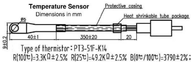
6.7 Crankshaft Position Sensor (CPS)
The Crankshaft Position Sensor (CPS) (Fig. 26) is an inductive pick-up that sends a signal to the ECU every time the engine goes by top dead center (TDC). It is mounted above the rotor as shown in Fig. 27. The ECU uses this sensor to time the ignition spark and the firing of the fuel injector. If a CPS malfunction is suspected follow the procedures for checking the coil resistance and setting the air gap (see air gap setting procedures when replacing the CPS).
6.7.1 Checking Coil Resistance
- Remove the control panel and carefully allow it to hang out of the way. Find the green 2-pin CPS connector with the blue and green wires (Fig. 26) and disconnect it.
- Check for continuity between both CPS wires and ground, there should be no continuity. If there is replace the CPS.
- Measure the resistance between the blue and green wires of the CPS connector to determine the coil resistance. Replace the CPS if it is out of the range shown below.
| CPS coil resistance | 95-110Ω |

natural_image
Close-up of a black cable with a green connector and a red circle highlighting it, labeled 'Fig. 26' (no text or symbols on the device itself)6.7.2 Adjusting the Air Gap of the CPS
- Follow steps 1 through 8 as outlined in section 9.1.
- Check the clearance between the CPS and the TDC block of the rotor by inserting a feeler blade (0.040"-0.050") between them (see Fig. 27). If the gap is correct there should be only slight resistance felt when sliding the feeler blade in between them. Adjust if necessary (step 3).
- Loosen the CPS bolts (circled in Fig. 27) and insert the feeler gauge. Allow the magnetic tip of the CPS to contact the feeler blade and retighten the bolts. Recheck the gap, adjust as necessary.
- Rotate the rotor to make sure there is no interference with any other rotor components.
- Re-assemble in the reverse order of disassembly.
| CPS sensor clearance | 1.0-1.2mm (0.040"-0.050") |

6.8 Load Controller
The load controller (Fig. 28) is an inductive sensor that is used by the ECU to determine the load conditions on the inverter so it can alter the throttle settings of the engine accordingly. If the engine will start and run, but bogs or dies when a load is placed on the generator, replace the load controller.
It also serves several other completely separate functions. The fuel pump relay (section 6.8.1), the inverter overload reset circuit (section 6.8.2), the amp and wattage signal for the digital display (section 7.2), and the timer for the remote switch flashing light (section 3.15.1) are all built into the load controller. A failure in any one of these functions necessitates the replacement of the load controller.
6.8.1 Fuel Pump Relay Test
The fuel pump relay is housed within the load controller, as an integral part of it. The load controller is located behind the control panel bolted on top of the inverter as shown in Fig. 29. If the fuel pump relay is suspected of malfunction or fault code (0230) has been read conduct the following test.

natural_image
Electronic component with black housing, white connectors, and visible brand labels (no readable text or symbols beyond label)
-
Turn the ignition key to the ON position while listening closely at the top of the fuel tank near the filler neck (remove the fuel cap if necessary). If the fuel pump relay is working properly it will turn the fuel pump on for several seconds when the key is turned on. If this occurs then the fuel pump relay is good, if not proceed to step 2. Skip this step if you have already completed it as part of the fuel pump test in section 6.10.1.
-
Remove the control panel and carefully allow it to hang out of the way. Remove the two bolts holding the load controller to the top of the inverter to allow better access. Leave the load controller connected as shown.
-
Using a voltmeter, connect the positive test lead to the red wire with black stripe marked 12VDC to Fuel Pump (Fig. 30) and the negative test lead to ground. Turn the ignition key to the ON position. The voltmeter should change from 0VDC to 12VDC for several seconds. If it does, then the fuel pump relay is working and the problem lies in the wire between the relay and the pump or the pump itself (see section 6.10.1). If you do not see 12VDC when the key is turned ON, then proceed to step 4.
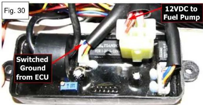
-
Put the test leads of an ohmmeter between the blue wire marked Switched Ground from ECU (shown in Fig. 30) and ground. There should be no continuity. Turn the ignition key to the ON position. The ohm reading should drop to 5-10Ω for several seconds and then return to having no continuity. If this occurs and the relay failed step 3, then the relay is faulty and the load controller must be replaced. If the ECU does not switch the blue wire to ground as described above, proceed to step 5.
-
Using a jumper wire provide ground to the blue wire from step 4 while checking the voltage on the red wire with the black stripe from step 3. If grounding the blue wire causes 12VDC to appear in the red wire with the black stripe then the fuel pump relay is working properly; proceed to step 6.
-
Remove the two ECU mounting screws but leave the ECU connected. Locate pin 15 on the ECU marked Switched Ground to the Fuel Pump Relay in Fig. 31. Put the test leads of an ohmmeter between the blue wire and ground. There should be no continuity. Turn the ignition key to the ON position. The ohm reading should drop to 5-10Ω for several seconds and then return to having no continuity. If the ECU does not switch the blue wire to ground as described then replace the ECU.
-
If the ECU does switch ground at pin 15 as described, but not at the load controller; then there look for a break or short in the blue wire between the ECU and the load controller. Repair as necessary and retest.
-
Upon test completion remount components and control panel.
6.8.2 Overload Reset Button Test
The overload reset button is used to reset the inverter after it has shut itself down due to being overloaded or shorted out. It is the green button located below the ignition key on the control panel (Fig. 32). It has two gray wires attached to the back of it which both go to different terminals on the load controller (Fig. 33). If pushing the overload button fails to reset the inverter conduct the following test.
-
Remove the gray wires from the back of the overload switch (Fig. 33). Depress the button and check continuity through the two terminals of the switch. If the continuity is good then the switch is good, continue the test. If there is no continuity replace the switch and verify normal operation of the overload reset button is restored.
-
Inspect both gray wires for breaks or shorts, repair if necessary. Verify continuity through both gray wires from the overload switch to the load controller. If both wires have good continuity then replace the load controller and verify that normal operation of the overload reset button is restored.
-
If the switch, wiring and load controller have all been verified as good components or replaced and the inverter still fails to reset, replace the inverter.


6.9 Fuel Injector
The fuel injector (Fig. 34) is a mechanical device that delivers the fuel to the engine and is controlled by a signal from the ECU. It is mounted on top of the throttle body and can be accessed through the maintenance door. It has a 2-pin connector that is held on the injector with a spring clip. The connector has a red and a black wire. The red wire receives battery voltage whenever the ignition key is in the ON position. The black wire is the signal wire from the ECU. The ECU will produce fault codes (0261) or (0262) if it senses a problem with the fuel injector. If these fault codes are present or the fuel injector is suspected of malfunction perform the following test. Make sure the battery is fully charged and the battery post connections are clean and tight before beginning the test.

natural_image
Mechanical component labeled Fig. 34, showing a cylindrical assembly with mounting bracket and shaft (no visible text or symbols)
- Wait 5-10 seconds after engine shutdown prior to removing fuel line to allow the fuel pressure to bleed off.
6.9.1 Fuel Injector Test
-
Make sure you have verified that the fuel pump (section 6.10), fuel pump relay (section 6.8.1) and CPS (section 6.7) are working before beginning this test. Remove the maintenance door and the control panel, carefully allowing it to hang out of the way.
-
Remove the spring clip from the 2-pin connector on the side of the fuel injector and disconnect it.
-
Turn the ignition key to the ON position and check the battery voltage. Check the voltage at the red wire of the 2-pin connector. It should be the same as the battery voltage within 0.5V. If not, then check the red wire for continuity, dirty connections or shorts. Repair as necessary.
-
Find the ECU in the area behind the control panel and disconnect the 18-pin connector. Inspect the resistance between the black wire at the 2-pin connector and the black wire with the white stripe on pin 17 of the ECU shown in Fig. 35 and in the wiring diagram in section 1.3. The resistance should be zero. Make sure there are no shorts to ground or to battery voltage. Repair as necessary. Reconnect the ECU.
-
Next remove the fuel injector in preparation to do a physical test. Remove the fuel injector bolt and bushing shown in Fig. 36. Gently pull the injector out. Remove the hose clamp and fuel hose from the injector cap, remember to wait 5-10 seconds after the ignition key has been turned off.
-
Remove the injector cap and inspect the cap and top of the injector (Fig. 37 and 38). Clean out any obstructions or debris using compressed air. Apply a thin film of motor oil or assembly lube on the upper fuel injector O-ring and reinstall the injector cap.

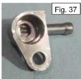
natural_image
Metal mechanical component with a pin and cylindrical shaft, labeled Fig. 37 (no text or symbols on the part itself)
natural_image
Close-up of a hand holding a black plastic connector with a circular top and internal slots (no text or symbols visible)
natural_image
Disassembled mechanical component with metallic and black parts, no visible text or symbols- If you have a fuel injector tester as shown (Fig. 39), then test the injector per tester instructions and verify its proper operation or replace it if necessary. If you don't have a fuel injection tester then pull the fuel line and fuel injection connector through the control panel opening and connect them to the fuel injector as shown (Fig. 40).

natural_image
Electrical testing setup with coiled wires, a test device, and clamp points (no visible text or symbols)Fuel Injector Tester

natural_image
Close-up of a hand holding a black connector with wires, next to an electronic device (no visible text or symbols)-
Hold the end of the fuel injector over a fuel safe container and turn the ignition key to the start position while watching the end of the fuel injector. It should produce a quick spray of fuel intermittently, timed with the cranking of the engine. The spray of fuel should look like the one in Fig. 41, if it is a good injector. If it produces no spray, drips, dribbles or produces an abnormal or weak spray; replace the injector and repeat the test.
-
If you have replaced the fuel injector and you still see no spray, then test the signal in the black from the ECU using a fuel injector pulse tester as shown (Fig. 42). Test the signal per the tester instructions and replace the ECU, if necessary. If you do not have a fuel injector pulse tester and you have tested the fuel injector and made sure there are no wiring issues, then replace the ECU.
-
Repeat the test to make sure normal fuel injector spray has been restored. Reinstall the fuel injector, ECU, control panel and maintenance cover. Apply a thin film of motor oil or assembly lube on the lower fuel injector O-ring before inserting it in its mounting hole.
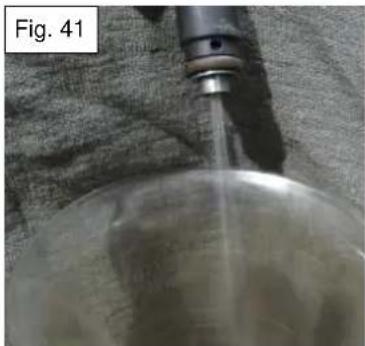
natural_image
Close-up of a metallic spherical object with a vertical jet or spray tube, resting on a textured fabric background (no text or symbols visible)
6.10 Fuel Pump
The PH4000Ri/E is equipped with an electric fuel pump mounted inside the fuel tank next to the filler neck (Fig. 43). The fuel pump needs to maintain 25psi in the system for proper operation of the fuel injector. If it suspected the fuel pump is faulty conduct the following test. Before beginning the test make sure the battery is fully charged and that the connections are clean and tight.

- Wait 5-10 seconds after engine shutdown prior to removing fuel line to allow the fuel pressure to bleed off.
6.10.1 Testing the Fuel Pump
-
Remove the maintenance door. Remove the fuel line from the top of the fuel injector and connect it to a fuel pressure testing gauge similar to the one shown in Fig. 44.
-
Turn the ignition key to the ON position while listening closely at the top of the fuel tank near the filler neck (remove the fuel cap if necessary). If the fuel pump is working properly it will come on for several seconds when the key is turned on, to bring the fuel pressure up to the required pressure before starting. Observe the test gauge while the pump is running and verify that the pressure reaches 25psi. If it does, then the pump is good and the test is complete. If the pump fails to come on proceed to step 3. If it comes on but does not come up to pressure proceed to section 6.10.2 to remove the fuel pump.
-
Remove the control panel and carefully let it hang out of the way. In the area behind control panel there are only two leads coming in from above the fuel tank. The lead with the 2-pin red connector and red and black wires is the one to the fuel pump (Fig. 43). Disconnect the fuel pump connector.
-
Using two jumper wires, connect the black wire from the fuel pump connector to the negative battery post, and the red wire from the fuel pump to the positive battery post (be ready to disconnect one the jumper wires in case of an internal short in the fuel pump). The fuel pump should come on. Verify that the pressure reaches 25psi on the test gauge, if so then the fuel pump is good. If the pump fails proceed to section 6.10.2 to replace the pump.

natural_image
Close-up of a mechanical device with black cable and red connector, labeled Fig. 43 (no visible text or symbols on the device itself)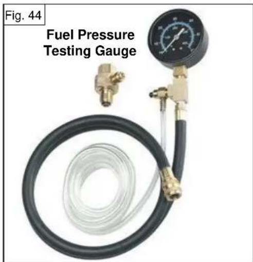
-
If the pump failed to come on in step 2, but passed step 4, first verify that the black wire to the pump is getting good ground from its mating wire in the harness. Repair if necessary. If the fuel pump is getting good ground then proceed to section 6.8.1 and test the fuel pump relay which is an integral part of the load controller.
-
Upon completion of a successful fuel pump test reconnect the fuel pump connector and reinstall the control panel, the fuel line on the fuel injector and the maintenance door.
6.10.2 Replacing and Servicing the Fuel Pump
-
Remove the access plugs on the side of the front and rear covers and remove both lift handles. Refer to section 8 for reference on these processes.
-
Remove the control panel and front cover. The control panel can be left connected and fed back through its hole in the front cover. The telescoping handles do not need to be removed to remove the front cover.
-
Remove the rear cover.
-
Remove the fuel cap and the top cover.
-
Disconnect the red 2-pin electrical connector. Loosen the hose clamp and remove the fuel line.
-
The fuel pump assembly is held in place by its rubber grommet. Grab the fuel pump body and twist it back and forth gently while lifting to remove the fuel pump assembly. Tip the fuel pump assembly as it is lifted to avoid knocking the fuel pump filter off the bottom of the pump as you bring it through the hole in the tank (Fig. 48).
-
If the fuel pump came on in step 2 of the fuel pump test section 6.10, but failed to build up sufficient pressure; check the fuel pump tube for splits or leaks, and the fuel pump filter for clogging (Fig. 49). Repair or replace as necessary. If the fuel pump filter was clogged, drain and thoroughly flush the fuel tank before beginning reassembly.
-
Inspect the pressure relief valve, housed below the fuel pump assembly outlet (see Fig. 49). The pressure relief valve assembly consists of a plunger, spring, and cap (see Fig. 45). Remove the pressure relief valve cap by gently prying one of the latches off its barb on the housing (see Fig. 46). Beware that the cap has some spring pressure on it. Remove the spring and the plunger, using needle nose pliers on the stem of the plunger (Fig. 47). Clean any obstructions or debris from the housing with compressed air. Inspect the housing bore and plunger O-ring for damage, replace if necessary. Apply a thin film of motor oil or assembly lube on the O-ring before reassembly. Reinstall the pressure relief valve assembly, be sure the cap completely engages the barbs.
-
If you have repaired the existing fuel pump, put it back in the tank and repeat step 4 of the fuel pump test section 6.10 to verify normal operation has been restored before continuing.
-
Install the new or repaired fuel pump assembly in the reverse order of removal.

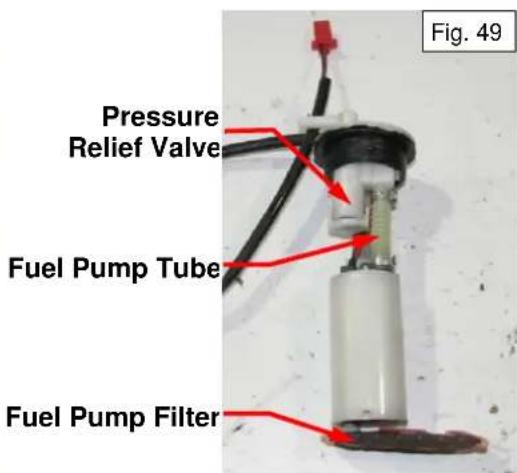
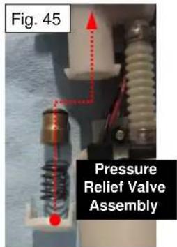

natural_image
Close-up of a mechanical assembly with a tool inserted, showing a red arrow indicating motion (no text or symbols present)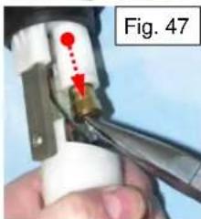
natural_image
Close-up of a hand using a tool to adjust or install a component, with red arrows indicating direction (no text or symbols visible)6.11 Intake Manifold
The intake manifold can be removed using the following procedure.
6.11.1 Intake Manifold Removal
- Remove the maintenance door and the control panel, carefully allowing it to hang out of the way.
- Remove the front lift handle.
- Remove the six front cover screws and remove the front cover. Gently maneuver the control panel back through the control panel hole in the front cover.
- Remove the carbon canister.
- Remove inverter bolts and gently lay the inverter on its back.
- Remove the four screws from the air filter cartridge and slide it out of the air cleaner. Remove the air cleaner cover.
- Remove the two nuts from the intake manifold studs and remove the air cleaner.
- Remove the fuel injector bolt and the fuel injector.
- Disconnect the step motor connector.
- Remove the intake manifold (circled below) by sliding it off its studs.

natural_image
Technical line drawing of an automotive assembly with components like motors, enclosures, and a highlighted valve (no text or labels present)6.12 Throttle Control – Step Motor
Before removing the step motor, inspect the inside of the intake manifold to make sure there are no physical obstructions that would prevent the free motion of the throttle plate.
6.12.1 Removal and Installation of Step Motor
- Remove the intake manifold by following steps 1-10 in section 6.11.1.
- Unplug the step motor.
- Remove the two step motor screws and carefully remove the step motor (Fig. 50). Take care not to dislodge the fork and fork spring located below the step motor bracket (Fig. 51). The spring is under compression and can be lost easily if allowed to fly off. It is not necessary to remove the step motor bracket to change the motor. Leave the bracket on to hold the fork and spring in place.
- Carefully align the flat on the shaft of the replacement step motor with the flat of the fork (indicated by arrow Fig. 51) when reinstalling the motor.
- Reinstall the intake manifold using the steps in section 6.11.1 in reverse order.
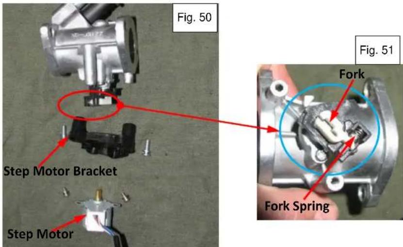
6.12.2 Resistance and Backlash of Step Motor
Before checking the resistance, gently rotate the step motor shaft back and forth between your thumb and forefinger to check the backlash of the step motor gears. There should be almost none. If the backlash is in excess of 0.010-0.015" then replace the step motor.
- Measure the resistance of the outlet terminals of the step motor.
| Resistance value | Pin 1-blue - Pin 2-white: 50-55Ω |
| Pin 3-red - Pin 4-black: 50-55Ω |
- Replace the step motor if the resistance exceeds the standard values.
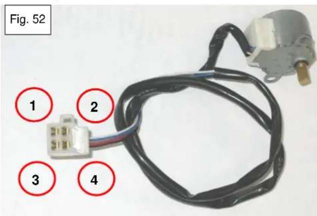
7. Control panel
7.1 Disassembly and installation

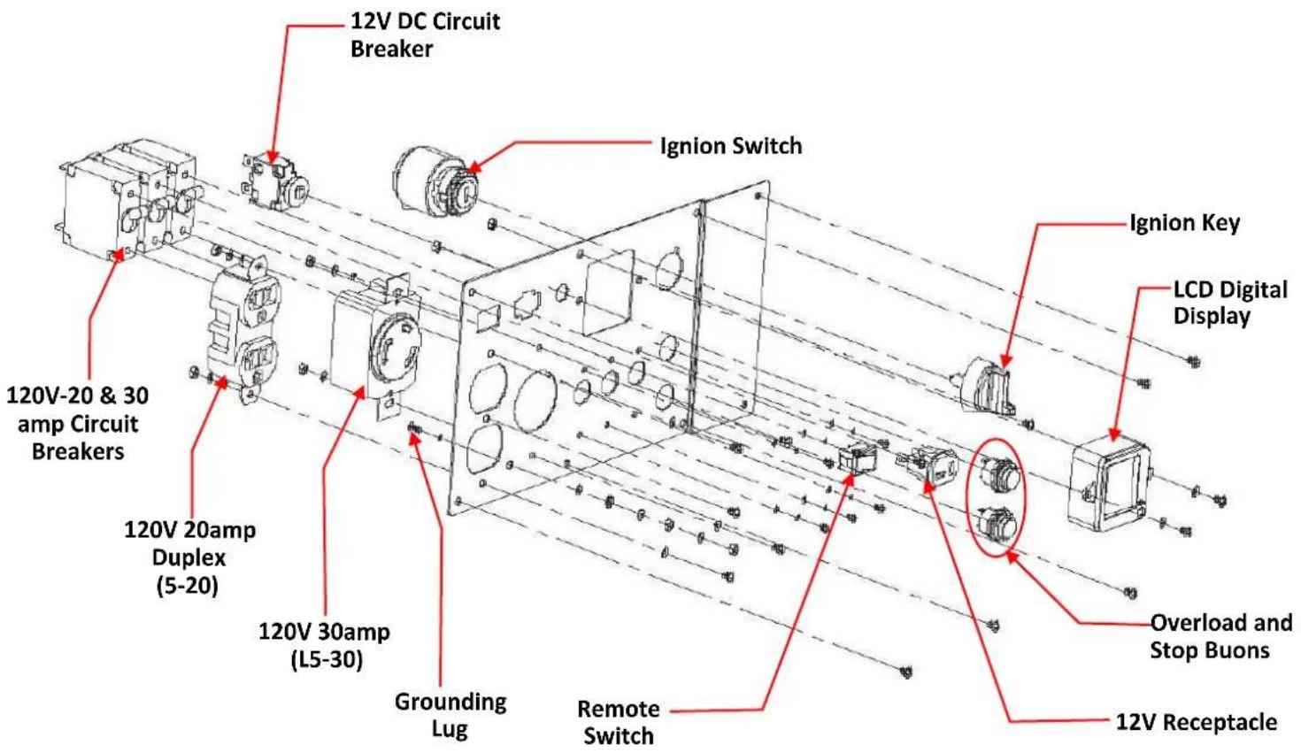
7.2 Digital Display
This generator is equipped with an LCD digital display in the control panel (Fig. 53) that provides continuously-updated status information for the following parameters:
(U) Voltage—Current voltage supplied
■ (I) Amperage for the generator output
■ (P) Wattage (power) output for the generator
■ (T) Run time—Total generator run time since first start (in hours)
■ (FUEL) Fuel level (bar reading)
The Low Oil/Fault Code Indicator light and the Fault Code Reset Button are also built into the digital display. The following sections detail how to diagnose problems with the different functions of the digital display. Before diagnosing problems with the digital display, make sure the battery is in good condition and fully charged (see section 3.1).

7.2.1 Voltage Display Field
The voltage displayed in voltage data field of the digital display is taken directly from the 120VAC receptacles on the control panel. If it is suspected that the voltage displayed is not correct, conduct the following test.
-
Turn the ignition key to the ON position. The display should illuminate and display 000.0V. If not, remove the control panel and check the red 2-pin connector coming from the digital display. The red wire should have 12VDC battery voltage and the black wire should have ground. If not, then inspect the wiring through to the 3-pin control panel connector and the voltage regulator for breaks or shorts (see section 3.3) and repair or replace accordingly. If the display has 12VDC battery voltage at the red wire and good ground on the black wire, but fails to illuminate or populate the display when the ignition key is turned ON, then replace the digital display and replace the control panel.
-
Start the generator. The digital display should illuminate and display the current voltage. Use a voltmeter to read the voltage between the hot and neutral contacts of one of the 20A receptacles on the control panel. The voltmeter and display voltage should agree within a volt or so (the voltmeter may respond to a voltage change more quickly than the display). If the voltage displayed does not agree with the voltmeter, proceed to step 3.
-
Shutdown the generator and remove the control panel. Find the white 2-pin connector from the digital display. Check the continuity from the red wire to the neutral side of the 120VAC receptacles. Check the continuity from the black wire to the unswitched side of the 20A and 30A breakers. If there is no continuity or there is resistance in these wires inspect them for breaks, shorts or bad connections. Replace or repair the wires as necessary. If there are no wiring issues found, or fixing the wiring issues has not restored proper voltage display, then replace the digital display.
7.2.2 Amperage and Wattage Display Fields
The amperage and wattage displayed by the digital display is taken directly from the loading signal from the load controller. Since the information for both of these displays come from the same signal, a loss of this signal will affect both displayed values simultaneously. If it is suspected that the amperage and wattage displayed is not correct, conduct the following test.
- Turn the ignition key to the ON position. The display should illuminate and display 00.0A. If not, remove the control panel and check the red 2-pin connector coming from the digital display. The red wire should have 12VDC battery voltage and the black wire should have ground. If not, inspect the wiring through to the 3-pin control panel connector and the voltage regulator for breaks or shorts (see section 3.3) and repair or replace accordingly. If the display has 12VDC battery voltage at the red wire and good ground on the black wire, but fails to illuminate or populate the display when the ignition key is turned ON, then replace the digital display and replace the control panel.
- Start the generator. The digital display should illuminate and display 0.00A and 0000W. Plug a small load into one of the receptacles and measure the amperage draw using a amp meter. The amp meter and display amperage should agree within ±5% (the amp meter may respond to amperage change more quickly than the display). Multiply the measured amperage times the displayed voltage (or measure the voltage at an empty AC receptacle) and compare it to the displayed wattage. The calculated and displayed wattage values should be within 5-10% of each other. If the displayed amperage and wattage are not correct, proceed to step 3.
- Shutdown generator and remove the control panel. Find the 16-pin connector from the control panel. Check the continuity from the pink wire from the digital display, through the 16-pin connector to the 5-pin connector on the load controller. If there is no continuity or there is resistance in this wire inspect it for breaks, shorts or bad connections. Replace or repair the wire as necessary. If there are no wiring issues found, or fixing the wiring issues has not restored proper amperage and wattage display, replace the load controller.
- If proper amperage and wattage display is not restored after completing steps 1-3, and replacing the load controller, then replace the digital display.
7.2.3 Hour Meter
The hour meter should read the total generator run time in hours, since its first start. It is an integral part of the digital display. The hour meter should be running any time there is 120VAC output to the receptacles on the control panel. Complete steps 1-3 of section 7.2.1 for the voltage display field, to make sure the digital display is getting the proper voltage it needs to operate. If the display passes steps 1-3 but the hour meter fails to begin recording time after 0.1hrs (6 min.) has passed, then replace the digital display.
7.2.4 Fuel Level Display
The fuel level is displayed in the bottom data field of the digital display. It is represented as a scale of 0-5 bars (0 bars=empty, 5 bars=full). It gets its signal from an electronic fuel gauge sending unit that is completely separate from the mechanical fuel level indicator viewed from the sight glass on the top of the fuel tank. If it is suspected the fuel level display is not correct conduct the following test.

NOTE
It should be noted that on the first production runs of the PH4000Ri/E the fuel level display will only indicate the fuel level while the generator is running. If the key is in the ON position, but the engine is not running, the display will indicate the battery voltage in the 0-5 bar scale. This will be changed so that the display indicates the fuel level whenever the key is in the ON position for all PH4000Ri/E generators after serial number 141227422302270.
- Remove the control panel and find the fuel gauge sending unit yellow 2-pin connector coming from the top of the fuel tank, into the open area behind the control panel. Disconnect the 2-pin connector.
- Check the continuity of the blue and black wires coming from the digital display through the 16-pin control panel connector and to the 2-pin connector of the fuel gauge sending unit. They should have no resistance. Repair or replace the wires as necessary.
-
Start the generator and connect the blue and black wires of the 2-pin connector with a jumper wire while watching the fuel level display on the digital display. The fuel level should drop to zero bars (empty) when the wires are jumped. This indicates a good display and that the fuel gauge sending unit needs inspected. If the fuel level display does not change to empty when the wires are jumped, replace the digital display.
-
Follow steps 1-4 in section 6.10.2 to gain access to the fuel gauge sending unit (Fig. 54). Gently pry the sending unit out with a broad, slotted screwdriver, working your way around it as required.
-
Put an ohmmeter across the two leads of the yellow 2-pin connector. Hold the body of the sending unit so the float can hang in the "EMPTY" position. The ohmmeter should read 30-40Ω. Lift the float slowly to the "FULL" position (see Fig. 54) while watching the ohmmeter. It should gradually change increase to 550-600Ω. Watch closely for open spots during the transition. If the fuel gauge sending unit does not operate in the 30-600Ω range, or you find open spots during the transition, replace the fuel gauge sending unit.
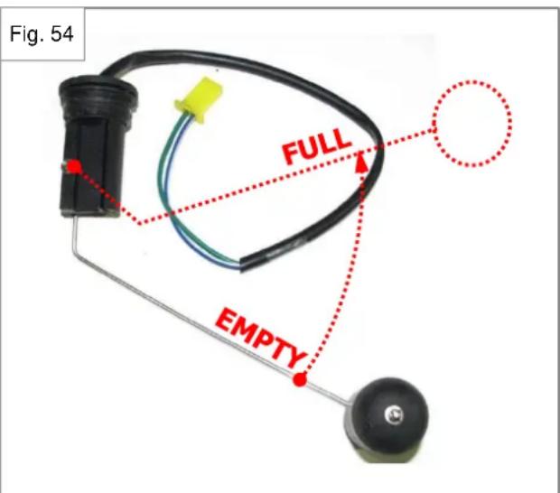
- Before re-installing the sending unit, reconnect the 2 pin connector, briefly start the generator and operate the sending unit through its complete range of motion while watching the fuel level display to verify the display is responding properly. Shut down the generator and re-install the sending unit and control panel in the reverse order of removal.
7.2.5 Low Oil Indicator Light
The Low Oil Indicator Light will illuminate steadily if the engine is low on oil, and blink on and off repeatedly to indicate that the ECU has stored EFI fault codes. If both conditions are true, it will stay on steadily until the low oil condition is remedied, and then blink repeatedly. If it is suspected that the engine is low on oil, but the light has not illuminated (see section 4.4 to check the oil level sensor), or the ECU has generated fault code (0650), then conduct the following test to determine if the indicator light is faulty.
- Remove the control panel to gain access to the back of the digital display.
- Turn the ignition key to the ON position.
- Find the white wire coming out of the back of the digital display and going to the 16-pin control panel connector. Connect a jumper wire from the negative terminal of the battery to the white wire while watching the low oil indicator light. It should illuminate red when the white wire is grounded. If it does not, replace the digital display.
7.2.6 Fault Code Reset Button
The Fault Code Reset Button is used to read the fault codes stored by the ECU. It is also used to erase the codes, as necessary, during the diagnostic process and after the repair process is complete.
To read the fault codes, while the ignition key is on, press the button briefly and the display will cycle through the fault codes in the Wattage (P) data field of the digital display. Fault codes are erased by holding the Fault Code Reset Button down for 10 seconds or more while the key is in the on position. The key must then be turned off to complete the process.
If the indicator light is blinking on and off repeatedly (indicating there are fault codes to read) but depressing the Fault Code Reset Button does not cause the fault codes to display in the wattage field of the display, then conduct the following test.
- Remove the control panel to gain access to the back of the digital display, 16-pin control panel connector, and the 18-pin ECU connector.
- Find the yellow wire coming out of the back of the digital display.
- Check the continuity of the yellow wire through the 16-pin connector of the control panel all the way to the 18-pin connector of the ECU (see the wiring diagram in section 1.3). Repair any breaks, shorts, or dirty connections and verify the resistance is at or close to 0Ω.
- Once it has been verified that there are no wiring issues, if the Fault Code Reset Button still fails to work, replace the digital display.
8. Outer Generator Housing
8.1 Disassembly and Installation

9. Recoil Starter Disassembly and Reassembly
- Disconnect the battery.
- Remove the control panel, carefully allowing it to hang out of the way.
- Remove the front lift handle.
- Remove the six front cover screws and remove the front cover. Gently maneuver the control panel back through the control panel hole in the front cover while removing it. Set the front panel aside, and carefully allow the control panel to hang out of the way. (Fig.55)
- Unbolt the carbon canister so it can be moved to aside for inverter removal.
- Remove inverter bolts and gently lay the inverter on its back (Fig. 56).
- Remove the three M6 flange bolts (circled in Fig. 56) and remove the recoil starter.
- Reinstall all components in reverse order.

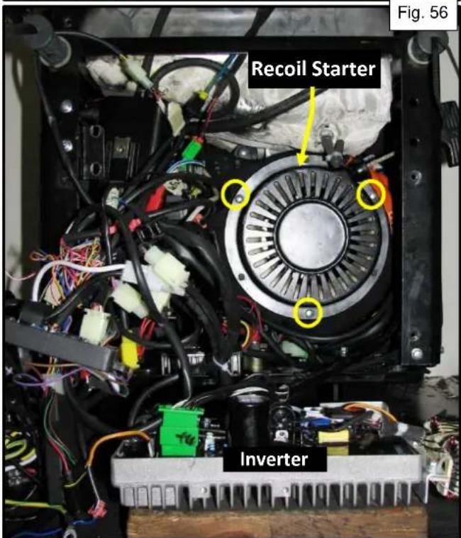
9.1 Intake Fan Cover
CAUTION
- Drain all gasoline from the fuel tank before disassembly.
-
Keep the unit away from all heat, flame and sparks.
-
Disconnect and remove the battery.
- Remove the front and rear end panels and the left and right side panels.
- Remove the upper frame and the gas tank as an assembly.
- Remove the inverter.
- Disconnect all wires from the stator assembly.
- Disconnect the starter motor wire and all ground wires.
- Remove 4 nuts from the engine mounting bolts (2 on each side) and lift the engine assembly off the base pan.
Upper Frame and Gas Tank
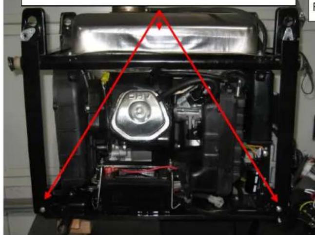
natural_image
Interior view of a vehicle chassis frame with red triangular annotations highlighting mechanical components (no text or symbols visible)Fig. 57
Fig. 58
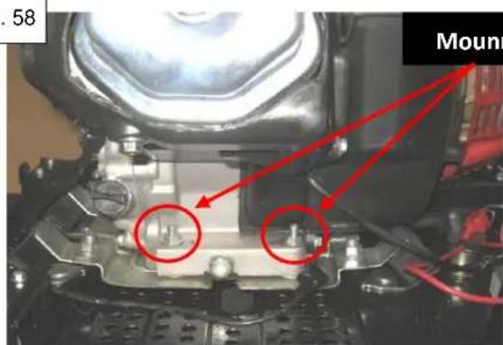
Mounng Bolts

Fig. 59
- Remove the intake manifold assembly and the intake fan cover.

9.2 Starter motor
9.2.1 Testing the Starter
Before beginning to test the starter, make sure the battery is fully charged and the terminal connections are clean and tight. See section 3.1 for battery charge requirements.
- Remove the front and rear end panels and the right side panel. It may be necessary to remove the right side wheel to gain access to the lower right side panel screw.
- Disconnect the cable from the starter relay, shown in Fig. 61.
- Attach a jumper cable to the positive battery terminal of sufficient length to reach the starter motor. It is important that the jumper wire's free end be at the starter, and not the battery, so that the sparks that may be generated during this process are not near the battery. The wire should be 10 or 12 gauge. Make sure the free end does not make contact with chassis ground. Touch the free end of the jumper to the starter connection for the starter relay cable. The starter should engage the ring gear and turn the engine at a normal cranking speed. If it fails to engage the ring gear, fails to crank or cranks very slowly, or produces excessive heat or smoke, replace the starter (see section 9.2).
- If the starter passes step 3, reconnect the cable from the starter relay. Turn the ignition key to the START position and verify that the starter performs as well as it did in step 3. If not, check the cable from the starter relay for breaks, shorts or bad connections. See section 3.2 if there are further problems.
Cable from Starter Relay
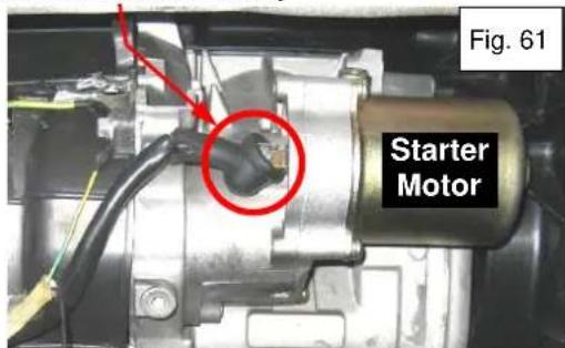
9.2.2 Removal and Replacement
- Remove the maintenance door and disconnect the battery.
-
Remove the front and rear lift handles and the front and rear end panels.
-
Remove the right side panel. It may be necessary to remove the right side wheel to gain access to the lower right side panel screw. The recoil rope can be left in the hole in the panel. Pull the rope, with the panel, very slowly until there is enough slack in the rope to set the panel down out of the way.
-
Remove the cable coming from the starter relay.
-
Remove the three screws and two M6 bolts from the starter access cover and remove the cover (Fig. 62). It may be necessary to remove the bolts holding the upper frame to the base to allow the fuel tank to be moved up slightly to gain access to the bolt indicated with a dotted circle. Also note that the cover is colored orange for the purposes of this manual, but is black in production.
-
Remove the two M8 starter bolts (Fig. 63) and remove the starter. Slowly turn the engine, by hand, through a full 360^ turn, while examining the ring gear. If the ring gear has sections of teeth badly worn or missing replace the rotor (see section 10).
-
Replace the starter using these steps in reverse order.

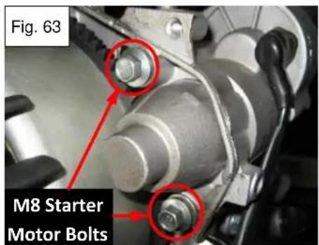
9.3 Starter relay
The starter relay is bolted to the chassis next to the voltage regulator, behind the inverter, and beneath the recoil starter, as shown in Fig. 64. Before beginning to test the starter relay, make sure the battery is fully charged and the terminal connections are clean and tight. See section 3.1 for battery charge requirements. Follow the 5 steps below to gain access to the starter relay. The starter relay can be tested on or off the generator. Refer to the procedures that follow.
- Remove the maintenance door and the control panel, carefully allowing it to hang out of the way.
- Remove the front lift handle.
- Remove the six front cover screws and remove the front cover. Gently maneuver the control panel back through the control panel hole in the front cover.
- Remove the carbon canister.
- Remove inverter bolts and gently lay the inverter on its back.
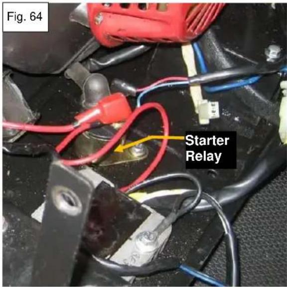
9.3.1 Testing Starter Relay on Generator
- First verify that the starter relay has good chassis ground. The relay body is grounded through its mounting bolts. Make sure the mounting bolts have good electrical contact with the chassis. It may be necessary to remove the paint around the mounting hole to accomplish this.
- Verify that there is 12V positive battery voltage at the battery terminal of the starter relay (Fig. 65). If not, clean battery connections or repair wiring as necessary to restore battery power to the battery terminal. Verify that there is no continuity between the battery and starter motor terminals of the starter relay.
- Turn the ignition key to the START position. Verify that there is 12V battery voltage being supplied to the spade terminal marked Start Wire from Ignition Switch in Fig. 65. If there is, the relay should make a single clicking sound, there should then be continuity between the battery and starter motor terminals of the starter relay, and the starter is turning, the relay is good.
- If the ignition switch failed to supply 12V battery voltage to the relay then test the ignition switch for the cause of the problem (see section 3.6.3) and continue this test using a jumper wire. Connect the jumper wire from the 12V positive terminal of the battery to the spade terminal of the relay (from step 3). The relay should click, there should be continuity between the battery and starter motor terminals, and the starter should be turning, if the relay is good. If there is no continuity between the battery and starter terminals, the relay needs to be replaced.
- If there is continuity between the terminals but the starter fails to turn, check the wire between the relay and the starter (Fig. 66) for breaks, shorts or dirty/loose connections. Repair as necessary. If good power is being supplied by the relay to the starter but the starter fails to operate properly see section 9.2 for starter service.

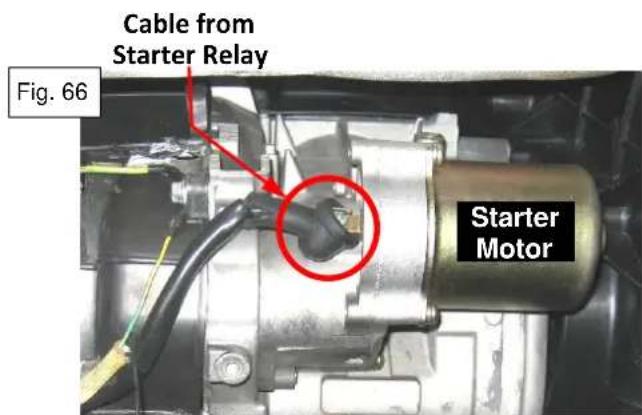
9.3.2 Bench Testing the Starter Relay
- Using a volt-ohm meter, check the resistances of the electromagnetic coil of the starter relay by connecting the red positive lead to the 14'' spade and the black negative lead to the metal body of the relay (Fig. 67).
| Resistance | 4.9 - 5.9 Ω |
- Check the function of the start relay by connecting the 14 " spade terminal to the 12V positive battery terminal. Connect the metal base or body to the negative battery terminal. There should be a clicking sound as the relay is activated. While the relay remains activated, use the volt-ohm meter to check continuity between the two lugs (Fig. 68). If there is no continuity the relay is defective.
There must only be continuity between the battery and starter terminals when the relay is activated.

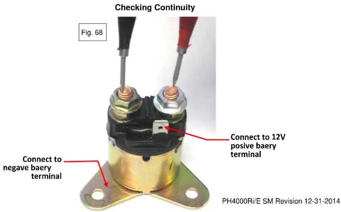
10. Stator and Rotor Disassembly and Reassembly
10.1 Stator Inspection
- Disconnect the battery.
- Remove the front panel.
- Remove the inverter.
- Locate the 6-pin connector at the inverter and unplug it.
- Locate the two pin connector from the stator and unplug it from the voltage regulator.
DC charging windings
Measure the resistance between the two blue terminals at the 2-pin connector.
| Resistance | Blue-Blue |
| 0.045-0.070 Ω |
Sub windings
Measure the resistance between the two sub winding terminals at the 6-pin connector.
| Resistance | White-White |
| 0.10-0.16 Ω |
Main windings
Measure the resistance between each of the main winding terminals at the 6-pin connector (Fig. 69).
| Resistance | Black-Black-Black |
| 0.25-0.35 Ω |
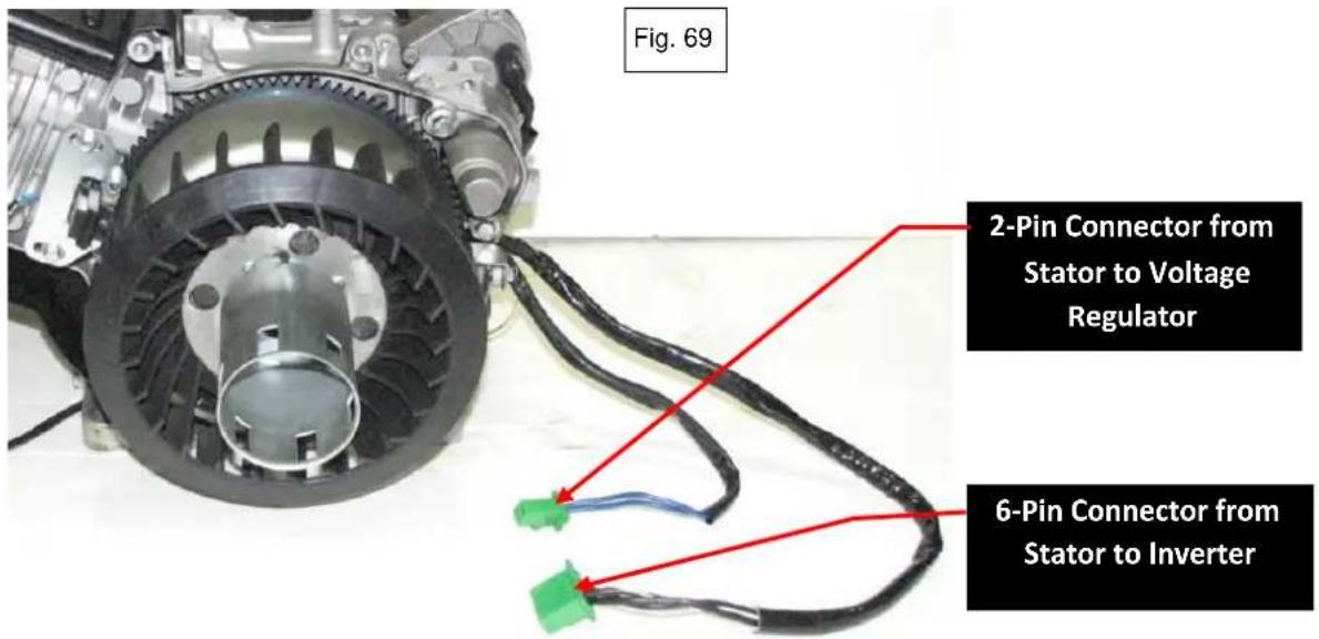
10.2 Stator Removal and Reassembly

CAUTION
- Drain all gasoline from the fuel tank before disassembly.
-
Keep the unit away from all heat, flame and sparks.
-
Disconnect and remove the battery.
- Remove the front and rear end panels and the left and right side panels.
- Remove the upper frame and the fuel tank as an assembly.
- Remove the inverter.
- Disconnect all wires from the stator assembly.
- Disconnect the starter motor wire and all ground wires.
- Remove 4 nuts from the engine mounting bolts (2 on each side) and lift the engine assembly off the base pan.
- Remove the intake manifold assembly and the intake fan cover.
- Remove the CPS, starter cup and fan (Fig. 70).
- Remove the M16 flange nut from the crankshaft (Fig. 70).
- Attach an appropriate puller to the rotor using three M6X1 bolts (grade 8.8 or better) and remove the rotor (Fig. 71).
- Remove the cable retainer clip and 4 stator mounting bolts using a M5 Allen wrench (Fig. 72).
- Reverse the procedure to reassemble.
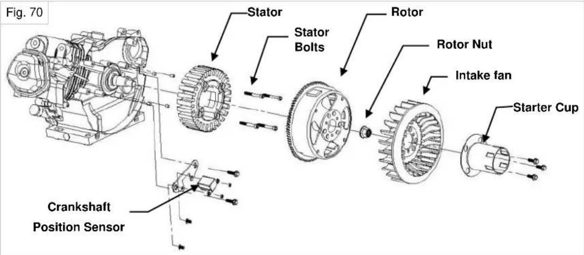

11. Exploded Engine View

| PH4000Ri/E Engine 177F | |||
| Ref # | MFR # | Stock | Description |
| 1 | 03051419 | -- | Drain Bolt |
| 2 | 03030167 | -- | Drain Bolt Gasket |
| 3 | 09080501 | -- | Crankcase, 177F |
| 4 | 09080506 | 69258 | Crankcase Gasket |
| 5 | 04030271 | -- | Crankcase Pin |
| 6 | 09070347 | 62512 | M10 Serrated Flange Nut |
| 7 | 09080509 | 69262 | Oil Level Sensor |
| 8 | 03050222 | 69351 | M6 X 16 Flange Bolt |
| 9 | 09080518 | -- | Connecting Rod Assy |
| 10 | 09080518 | -- | Connecting Rod Assy |
| 11 | 09080518 | -- | Connecting Rod Assy |
| 12 | 09080503 | -- | Crankshaft |
| 13 | 07190223 | 64233 | Bearing 6206 |
| 14 | 68183 | 69259 | Dipstick |
| 15 | 09080552 | 69260 | O-Ring, Dipstick |
| 16 | 09080502 | -- | Crankcase Cover, 177F |
| 17 | 04090021 | 69261 | Oil Seal |
| 18 | 03050225 | 69614 | M8 X 35 Flange Bolt |
| 19 | 09080514 | -- | Piston Pin Clip |
| 20 | 09080513 | -- | Piston Pin |
| 21 | 09080512 | -- | Piston |
| 22 | 09080517 | -- | Oil Ring Assy |
| 23 | 09080516 | -- | Second Piston Ring |
| 24 | 09080515 | -- | Top Piston Ring |
| 25 | 09080511 | 65113 | Camshaft Assy |
| 26 | 09080507 | 69266 | Head Gasket |
| 27 | 09080523 | 69267 | Valve Tappet |
| 28 | 09080522 | -- | Valve Push Rod |
| 29 | 03071201 | -- | Pin, Cylinder Head |
| 30 | 09080530 | 69268 | Intake Valve |
| 31 | 09080531 | 69269 | Exhaust Valve |
| 32 | 03050627 | -- | Intake Manifold Stud, M8 X 106.5 |
| 33 | 09080504 | 69264 | Cylinder Head |
| 34 | 03050626 | -- | Exhaust Manifold Stud |
| 35 | 09080534 | 69558 | Guide Plate |
| 36 | 09070376-1 | 62475 | Valve Adjusting Stud |
| 37 | 09080525 | 69562 | Rocker Arm |
| 38 | 09080524 | 62479 | Adjustment Nut |
| 39 | 09074014 | 69569 | Valve Adjusting Jam Nut |
| 40 | 09080521 | 69568 | Valve Spring Washer |
| 41 | 09080519 | 69561 | Valve Spring |
| 42 | 09070221 | 69564 | Intake Valve Spring Cup, Top |
| 43 | 09080520 | 69563 | Exhaust Valve Spring Cup, Top |
| 44 | 09080526 | -- | Valve Adjustment Spacer |
| 45 | 09080151 | 69537 | Spark Plug, F7RTC |
| 46 | 03050295 | 62489 | Cylinder Head Bolt |
| 47 | 09080508 | 60554 | Valve Cover Gasket |
| 48 | 09080533 | 69265 | Valve Cover |
| 49 | 09070429 | 69263 | Seal, Valve Cover |
| 50 | 03030168 | -- | Washer |
| 51 | 03050628 | 62590 | Valve Cover Bolt |
12. Cylinder Head / Valves
12.1 Cylinder Head Removal

CAUTION
- Drain all gasoline from the fuel tank before disassembly.
-
Keep the unit away from all heat, flame and sparks.
-
Disconnect and remove the battery.
- Remove the front and rear end panels and the left and right side panels.
- Remove the upper frame and the fuel tank as an assembly.
- Remove the inverter
- Remove the air cleaner and throttle body assembly.
- Remove the intake fan cover.
- Remove the muffler cover, muffler, exhaust fan, exhaust manifold and muffler case (Fig. 73, 74, 75).
- Remove the upper and lower engine covers (Fig. 76).
- Remove the valve cover and 4 - M10 head bolts.
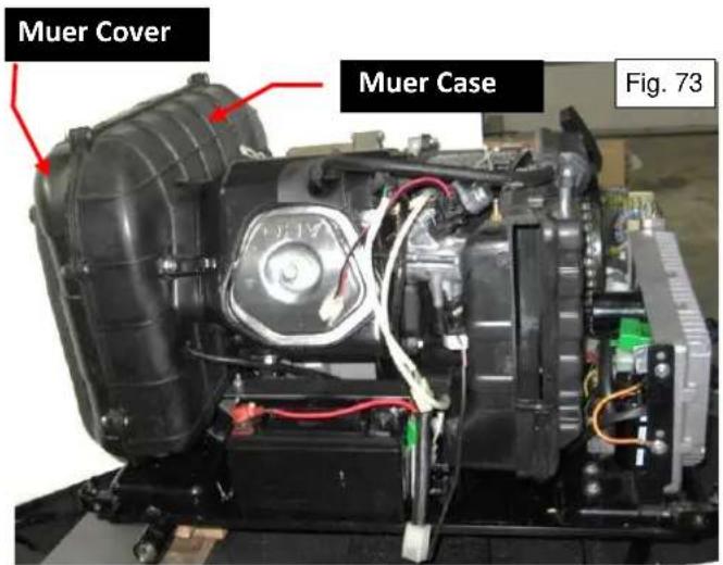

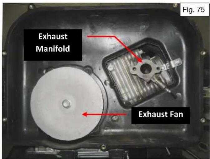


12.2 Cylinder Head Disassembly and Reassembly
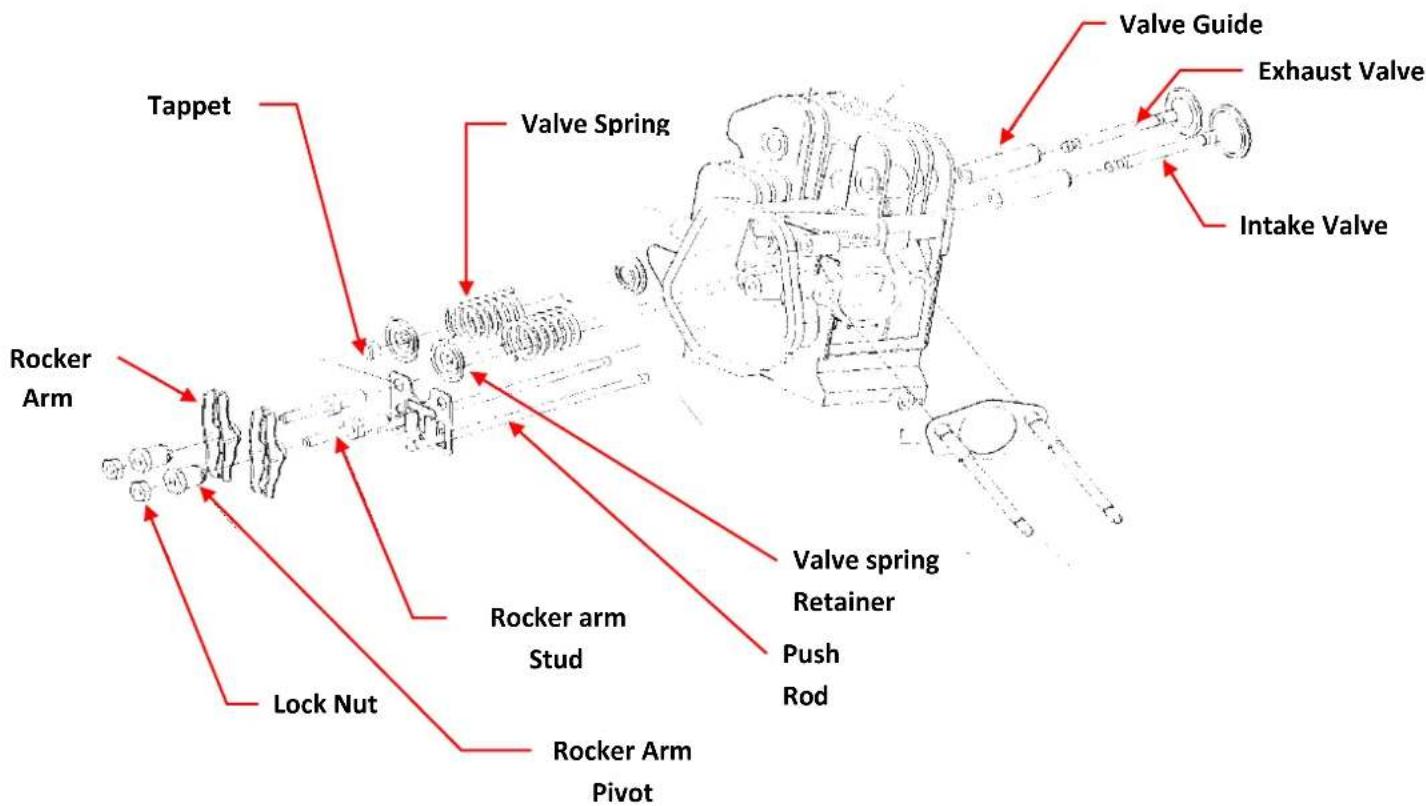
12.3 Inspection
• Free length of valve spring
| Standard | Service limit |
| 39.1mm (1.54") | 37.5mm (1.48") |

natural_image
Technical line drawing of a mechanical component with helical grooves and mounting brackets (no text or symbols)- Valve seat width
| Standard | Service limit |
| 0.8mm (0.03") | 1.8mm (0.07") |

natural_image
Technical line drawings of mechanical components, including a funnel and clamp assembly (no text or symbols)- Valve stem outer diameter
| Standard | Service limit | |
| Inlet valve | 6.465-6.480mm (0.2545"-0.2551") | 6.40mm (0.2520") |
| Exhaust valve | 6.455-6.470mm (0.2541"-0.2547") | 6.40mm (0.2520") |
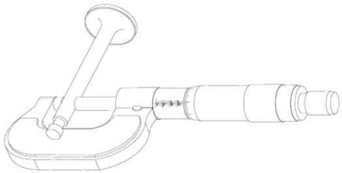
natural_image
Line drawing of a micrometer caliper with handle and base mount (no text or symbols)13. Crankshaft / Piston
13.1 Crankshaft, Camshaft and Piston

13.2 Alignment of Timing Marks
Use marks to align camshaft gear and timing gear during installation.

13.3 Camshaft Inspection
- Height of camshaft
| Standard | Service limit | |
| Intake/Exhaust | 31.700-31.780mm (1.2480"-1.2512") | 31.0mm (1.2205") |

natural_image
Technical line drawing of a mechanical gear assembly (no text or symbols)13.4 Piston / Connecting rod
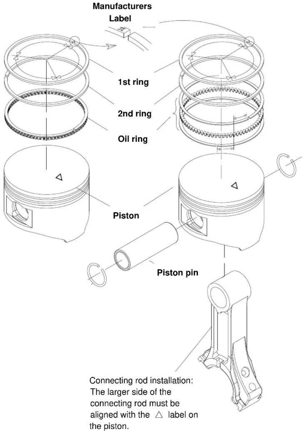
Assembly of piston rings

CAUTION
■ Make sure the rings are installed with the manufacturer's label up.
■ Make sure the 1st ring and 2nd ring are not interchanged.
■ Make sure the piston rings are free to move after installation.
■ Stagger each piston ring gap 120^ from each of the other rings.

• Cylinder inner diameter
| Standard | Service limit |
| 77.000-77.020mm (3.0315"-3.0323") | 77.105mm (3.0356") |
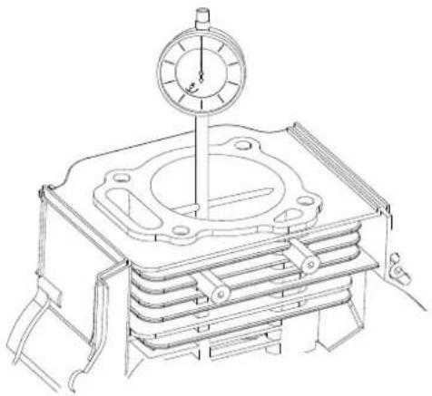
natural_image
Technical line drawing of a mechanical device with a dial indicator (no text or symbols)- Piston skirt outer diameter
| Standard | Service limit |
| 76.960-76.980mm (3.0299"-3.0307") | 76.85mm (3.0256") |

- Side clearance of piston ring
| Standard | Service limit |
| 0.02-0.06mm (0.001”-0.002”) | 0.15mm (0.006”) |

natural_image
Technical line drawing of a piston and lever assembly (no text or symbols)- Piston ring end clearance
Locate the piston ring into cylinder with piston top, and measure the piston end clearance.
| Standard | Service limit |
| 0.15-0.25mm (0.006"-0.010"). | 1.0mm (0.040") |
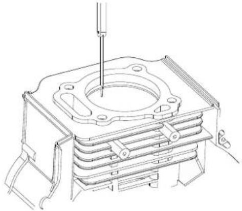
natural_image
Technical line drawing of a mechanical assembly with a central component and mounting base (no text or symbols)- Piston ring height
| Standard | Service limit | |
| The 1 ^st ring | 1.97-1.99mm (0.0776"-0.0783") | 1.87mm (0.0736") |
| The 2 ^nd ring | 1.97-1.99mm (0.0776"-0.0783") | 1.87mm (0.0736") |

natural_image
Line drawing of a micrometer caliper (no text or symbols present)- Piston pin outer diameter
| Standard | Service limit |
| 17.994-18.000mm (0.7084"-0.7087") | 17.95mm (0.7067") |

natural_image
Technical line drawing of a micrometer caliper (no text or symbols present)- Piston pin hole inner diameter
| Standard | Service limit |
| 18.002-18.008mm (0.7087"-0.7090") | 18.05mm (0.7106") |
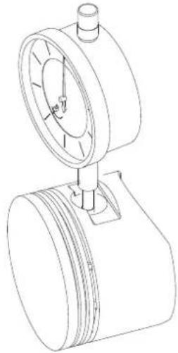
natural_image
Technical line drawing of a mechanical device with a cylindrical component and a dial (no text or symbols)- Connection rod small end inner diameter
| Standard | Service limit |
| 18.006-18.017mm (0.7089"-0.7093") | 18.08mm (0.7118") |

natural_image
Technical line drawing of a mechanical gauge or dial assembly (no text or symbols)- Connection rod big end inner diameter
| Standard | Service limit |
| 33.020-33.033mm (1.3000"-1.3005") | 33.09mm (1.303") |

natural_image
Technical line drawing of a mechanical gauge or dial assembly (no text or symbols)- Crankshaft neck outer diameter
| Standard | Service limit |
| 32.967-32.980mm (1.2979"-1.2984") | 32.90mm (1.295") |

natural_image
Technical line drawing of a mechanical assembly with cylindrical components and flanged ends (no text or symbols)- Connection rod big end side clearance
| Standard | Service limit |
| 0.1-0.4mm (0.004"-0.016") | 0.8mm (0.030") |

natural_image
Technical line drawing of an internal combustion engine cylinder (no text or labels)POWERHOUSE Products
DTS Manufacturing
7930 S.W. Burns Way, Unit C
Wilsonville, OR 97070
PH4000Ri/E SM Revision 12-31-2014
© 2014 DTS Manufacturing
All Rights Reserved
www.powerhouse-products.com
- CONTENTS
- PREFACE....2
- CONTENTS....3
- SPECIFICATIONS....6
- Service Information ....9
- Trouble Shooting....13
- Maintenance....32
- SPECIFICATIONS
- SPECIFICATIONS
- Service Information
- The Importance of Proper Servicing
- CAUTION
- Important Safety Precautions
- WARNING
- Service Rules
- Electrical Precautions
- Serial Number Location
- Trouble Shooting
- Battery Charge Requirements
- Cranks But Doesn't Start
- Hard Starting (cranks & starts, but is hard to start)
- Cylinder Compression Check
- Ignition System
- Checking for Spark
- Ignition Coil Inspection
- Ignition Switch Inspection
- Oil level sensor fails to stop engine when oil is low
- Engine stops running
- Engine speed can't increase, is unstable or is hunting
- Engine speed too high
- Engine Overspeed Protection
- No or Low AC Output
- Measuring stator output voltage while running
- No DC output at battery charge receptacle
- Battery will not charge
- Engine will not start or stop with remote.
- Remote Switch Inspection
- Maintenance
- Maintenance schedule
- Notes:
- Checking the oil level
- Changing oil
- NOTE
- Checking the Oil Level Sensor
- Air Cleaner
- Inspection and cleaning:
- Spark plug
- Valve clearance
- Inspection and adjustment:
- Evaporation Control System
- Fuel Filter
- Replacing Fuel Filter:
- Muffler system
- Spark arrestor
- Muffler Removal
- Disassembly and reassembly
- Electronic Fuel Injection (EFI)
- Overview of EFI System
- Engine Control Unit (ECU)
- Removal and installation of ECU
- Fault Codes
- Reading Fault Codes
- Fault Code Definition and Descriptions
- Manifold Air Pressure Sensor (MAP)
- MAP Voltage Output Test
- Oxygen Sensor ( O_2 )
- O₂ Sensor Output Test
- Replacing the Q Sensor
- Temperature Sensor
- Temperature Sensor Test
- Crankshaft Position Sensor (CPS)
- Checking Coil Resistance
- Adjusting the Air Gap of the CPS
- Load Controller
- Fuel Pump Relay Test
- Overload Reset Button Test
- Fuel Injector
- Fuel Injector Test
- Fuel Pump
- Testing the Fuel Pump
- Replacing and Servicing the Fuel Pump
- Intake Manifold
- Intake Manifold Removal
- Throttle Control – Step Motor
- Removal and Installation of Step Motor
- Resistance and Backlash of Step Motor
- Control panel
- Disassembly and installation
- Digital Display
- Voltage Display Field
- Amperage and Wattage Display Fields
- Hour Meter
- Fuel Level Display
- Low Oil Indicator Light
- Fault Code Reset Button
- Outer Generator Housing
- Disassembly and Installation
- Recoil Starter Disassembly and Reassembly
- Intake Fan Cover
- Starter motor
- Testing the Starter
- Removal and Replacement
- Starter relay
- Testing Starter Relay on Generator
- Bench Testing the Starter Relay
- Stator and Rotor Disassembly and Reassembly
- Stator Inspection
- DC charging windings
- Sub windings
- Main windings
- Stator Removal and Reassembly
- Exploded Engine View
- Cylinder Head / Valves
- Cylinder Head Removal
- Inspection
- Crankshaft / Piston
- Crankshaft, Camshaft and Piston
- Alignment of Timing Marks
- Camshaft Inspection
- Piston / Connecting rod
- Assembly of piston rings
- - Piston ring end clearance
- - Piston ring height
- - Piston pin outer diameter
Brand : Powerhouse
Model : PH4000RiE
Category : Generator