CIM0430FA - Ice machine Ice-O-Matic - Free user manual and instructions
Find the device manual for free CIM0430FA Ice-O-Matic in PDF.


| Brand | Ice-O-Matic |
| Model | CIM0430FA |
| Product Type | Cube Ice Maker |
| Ice Production Capacity | Up to 430 lbs per day (estimated) |
| Ice Types | Half Cube and Full Cube |
| Batch Weight (Half Cube) | 4.9 - 5.15 lbs |
| Batch Weight (Full Cube) | 5.5 - 5.8 lbs |
| Recommended Bridge Thickness | 1/8 inch (for models 400 lbs and above) |
| Cooling Type | Air Cooled (self-contained) |
| Ambient Operating Temperature | 50°F to 100°F (10°C to 38°C) |
| Water Supply Temperature | 40°F to 100°F (4.5°C to 38°C) |
| Water Supply Pressure | 20 psi to 80 psi (1.4 bar to 5.5 bar) |
| Electrical Requirements | Refer to serial plate; dedicated circuit required. Not for GFI outlets. |
| Clearance Requirements | 6 inches (15 cm) on rear, top, and sides for air circulation |
| Water Connection | 3/8 inch FPT potable water inlet |
| Drain Connections | Bin drain and purge drain: 3/4 inch FPT |
| Control System | CIM Control Board with LED status indicators (red, blue, yellow) |
| Cleaning Cycle | Automatic cleaning cycle (descale and sanitize) initiated by CLEAN button |
| Manual Harvest | Press and hold POWER button for 3 seconds |
| Warranty | Parts and labor coverage; register at www.iceomatic.com |
| Safety Precautions | Disconnect power and shut off water before maintenance; wear protective eyewear |
| Installation Notes | Not for outdoor use; level within 1/8 inch in all directions |
| Remote Condenser Option | Available with line set up to 75 ft actual length (100 ft equivalent). Max rise 35 ft, max drop 10 ft. |
Frequently Asked Questions - CIM0430FA Ice-O-Matic
User questions about CIM0430FA Ice-O-Matic
0 question about this device. Answer the ones you know or ask your own.
Ask a new question about this device
Download the instructions for your Ice machine in PDF format for free! Find your manual CIM0430FA - Ice-O-Matic and take your electronic device back in hand. On this page are published all the documents necessary for the use of your device. CIM0430FA by Ice-O-Matic.
USER MANUAL CIM0430FA Ice-O-Matic
Ice. Pure and Simple

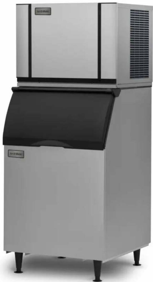
ELEVATION SERIES CUBE ICE MAKER
CIM 300 lb through 600 lb Cubers
natural_image
Exterior view of a modern ice cream maker with black lid and control panel (no visible text or symbols)Installation Guide and Owner's Manual
Ice-O-Matic
11100 East 45th Avenue
Denver, Colorado 80239
1-800-423-3367
9081484-01 REV. A
Energy Efficiency
Ice-O-Matic has partnered with ENERGY STAR since 2004 to ensure our customers receive the most efficient ice machines for your investment dollar. Ice-O-Matic is committed to the continuous improvement in both energy efficiency and productivity thereby delivering the best value in energy efficient ice machines money can buy.
For a detailed list of ENERGY STAR qualified Ice-O-Matic ice machines, go to:
http://www.iccomatic.com/Products/Sales-Literature/#
Freight Claims
Inspect Promptly
This merchandise has been carefully inspected and packed in accordance with the carrier's packing specifications. Responsibility for safe delivery has been assumed by the carrier. If loss or damage occurs, you as the consignee must file a claim with the carrier and hold the container for carrier's inspection.
Concealed Loss or Damage
If loss or damage does not appear until merchandise has been unpacked, make a written request for inspection by the carrier within 15 days of the delivery date, then file a claim on a form from the carrier.
Visible Loss or Damage
Any external evidence of loss or damage must be fully described and noted on your freight bill or express receipt and signed by the carrier's agent. The claim should be filed on a form available from the carrier.
FILE CLAIMS WITHOUT DELAY
DO NOT RETURN DAMAGED GOODS TO ICE-O-MATIC
How to use this Manual
Ice-O-Matic provides this manual as an aid to the service technician in installation and maintenance of the CIM Series cube ice machines. Do not attempt to perform installation, start-up or maintenance unless you have read and fully understand this manual.
Ice-O-Matic ice-makers and dispensers are not approved for outdoor installation.
For a Service Provider, please reference our "Find a Service Technician" tab at www.iceomatic.com Keep this manual for future reference.
The CIM Series Service Parts Manuals are available separately.
WARNING
Always disconnect electrical power and shut off water supply whenever maintenance or repairs are performed on the ice machine and related equipment.
CAUTION
Always wear protective eyewear whenever maintenance or repairs are performed on the ice machine and related equipment.
Ice-O-Matic Warranty
Every Ice-O-Matic ice maker is backed by a warranty that provides both parts and labor coverage. To view the warranty details, register products, or check your warranty status visit the “Warranty and Water Filter Registration” page on www.iceomatic.com
Installation Guidelines
Water Filtration/Treatment
For proper operation of the ice machine, the following installation guidelines must be followed by a qualified refrigeration technician. Failure to do so may result in loss of production capacity, premature part failures, and may void all warranties.
Reference the installation parameters prior to installing the machine. Ice-O-Matic assumes no responsibility for improperly installed equipment. Excessive time required for service or time for units requiring removal for service of inaccessible equipment will be the sole responsibility of the equipment owner.
Ambient Operating Temperature
Minimum operating temperature: 50^ F ( 10^ C)
Maximum operating temperature: 100^ F ( 38^ C) (60 Hz.), 110^ F ( 43^ C) (50 Hz.).
Note: Ice-O-Matic ice-makers and dispensers are not approved for outdoor installation
Incoming Water Supply
(see Electrical and Plumbing diagrams for line sizing)
Minimum incoming water temperature: 40^ F ( 4.5^ C)
Maximum incoming water temperature: 100^ F ( 38^ C)
Minimum incoming water pressure: 20 psi (1.4 bar, 0.138MPa)
Maximum incoming water pressure: 80 psi (5.5 bar, 0.552MPa)
Note: if water pressure exceeds 80 psi (4.1 bar), a water pressure regulator must be installed
All water supply lines must be installed per local codes. Use 3/8 inch O.D. minimum on air cooled machines. On water cooled machines 3/8 inch O.D. minimum tubing must be run to the condenser. The water supply for the machine can “T” off from the condenser line using 3/8 inch O.D. minimum tubing. Make 2 coils of extra tubing so that the machine can be pulled away from the wall if service is needed.
A water filter system should be installed with the ice machine. Refer to Ice-O-Matic water filter specification sheet.
Reverse Osmosis (RO) water can be very acidic and can attack the evaporator and other metal in the ice machine. Because the RO process removes all minerals and metals from the water it can promote the faster growth of microbial mold and slime. If RO water is used, Ice-O-Matic recommends the water pH is verified to be a neutral 7.0 to minimize the corrosive effects. Incorrect cleaners, sanitizers, and RO water that does not have a neutral pH could void the machine's warranty.
Drains
All drain lines must be installed per local codes. Flexible tubing is not recommended. Route bin drain, purge drain and water condenser drain individually to a floor drain. The use of condensate pumps for draining water is not recommended. Ice-O-Matic assumes no responsibility for improperly installed equipment.
Note: The purge drain fitting is plastic: DO NOT apply heat to purge drain area; DO NOT over-tighten drain connection.
All drain lines must be installed per local codes. The purge drain should be a minimum of 3/4 inch O.D. tubing. The condenser drain on water cooled units should be 1/2 inch O.D. minimum. The drain line fittings on Ice-O-Matic bins are 3/4 FPT. The bin drain should be a minimum of 3/4 inch O.D. Cold water drains should be insulated to prevent condensation from forming.
Clearance Requirements
Self-contained air cooled ice machines must have a minimum of 6 inches (15cm) of clearance at the rear, top, and sides of the ice machine for proper air circulation. Appropriate space should be allowed for proper serviceability of the machine.
All air cooled units have both top and side air discharge. Top louvers must not be blocked more than 75% for proper function of ice machine.
Stacking
Ice-O-Matic does not endorse stacking ice machines.
Dispenser Application
A thermostatic bin control kit should be installed if the CIM Cube ice machine is placed on a dispenser. A bin top may or may not be required and should be secured to the dispenser.
Electrical Specifications
Refer to the serial plate at the rear of the ice machine to make sure proper voltage and circuit breaker size have been supplied. Make sure the machine is on a dedicated circuit. European installations require that the electrical supply fixed wiring must be provided with a disconnect means having a separation of at least 3mm in all poles. The ice machines are provided without an electrical cord set and are designed and agency approved to be permanently connected.
Units are not approved for GFI outlets.
Caution: Electrical connection must be made or a cord installed by a qualified electrician or there is danger of an electrical fire.
Adjustments
Level the machine within 1/8 inch in all directions. Check the water in the Water Sump for proper level.
Check the ice bridge for proper thickness. Check the Water Regulating Valve adjustment if water cooled.
Secure the machine on top of the bin or dispenser. Attach the ice machine to the bin with the mounting straps provided with the bin or dispenser. Insure that the back of the ice machine is flush with the back of the bin. Proper functioning of the Bin Door requires the door, when it is opened, to be in a stable position.
If the ice machine is too far forward on the bin, the opened door may not be stable, resulting in an unexpected closing of the bin door. If the ice machine is to be mounted on a bin or dispenser other than an Ice-O-Matic, refer to the manufacturers instructions for machine mounting. Ice-O-Matic will not be responsible for damage or injury that results from unexpected closing of the bin door as a result of the ice machine being too far forward on the bin.
Remote Condenser Installation
For proper operation of the ice machine, the following installation guidelines must be followed. Failure to do so may result in loss of production capacity, premature part failure, and may void all warranties.
Use the following for planning the placement of the remote condenser relative to the ice machine
Location Limits
Remote condenser location must not exceed ANY of the following:
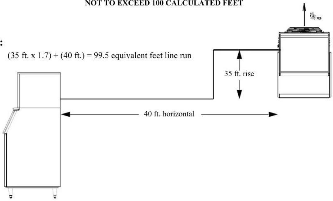
Maximum rise from the ice machine to the remote condenser is 35 physical feet.
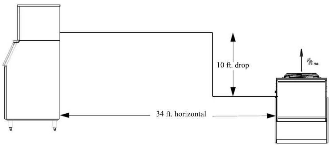
Maximum drop from the ice machine to the remote condenser is 10 physical feet.
Physical line set maximum length is 75 ft.
Calculated line set length maximum is 100 ft.
Ambient operating temperatures: -20°F (-28.9°C) to 120°F (48.9°C)
Roof Attachment
Install and attach the remote condenser to the roof of the building using the methods and practices of construction that conform to the local building codes, including having a roofing contractor secure the remote condenser to the roof.
Have an electrician connect the remote condenser fan motor wires to the ice machine using the junction box at the back of the machine.
Calculation Formula
$$ \mathrm{Drop} = \mathrm{dd} \times 6. 6 $$
$$ (\mathrm{dd} = \text { drop distance (ft. })) $$
$$ \text { Rise } = \mathrm{rd} \times 1. 7 $$
$$ (r d = \text { rise distance (ft.)) } $$
$$ \text { Horizontal Run } = \mathrm{hd} $$
$$ (h d = \text { horizontal distance (ft.)) } $$
Calculated Line Length = Drop + Rise + Horizontal Run
Pre-charged Line Set Routing
CAUTION: Do not connect the pre-charged tubing until all routing and forming of the tubing has been completed. See the coupling instructions for connecting information.
Each set of pre-charged tubing refrigerant lines consists of a 3/8 diameter liquid line and 1/2 inch diameter discharge line. Both ends of each line have quick connect couplings, one end of the line set has a Schrader valve connection.
Configurations that do NOT meet these requirements must receive written auth from Ice-O-Matic. This includes multi-pass or rack system remote condensers.
DO NOT: Route a line set that rises, then falls, then rises or a line set that falls, then rises, then falls.
Remote Condenser Location
Pre-charged line sets are available in 25, 40, 45, 60 or 75 foot length to connect the ice machine to the remote condenser. Select the best available location, protecting the remote condenser from extremes of dirt, dust and sun. Meet all applicable building codes. The services of a licensed electrician may be required.
r Note: the openings in the building or ceiling or wall, listed in the next step, are the minimum sizes recommended for passing the refrigerant lines through.
Have a roofing contractor cut a minimum hole for the refrigerant lines of 2.50 inch. Check local codes, a separate hole may be required for the electrical power to the condenser.
CAUTION: DO NOT KINK OR CRIMP REFRIGERANT TUBING WHEN INSTALLING IT.
Route the refrigerant lines through the roof opening. Follow straight line routing whenever possible. Any excess tubing MUST remain with the building. Spiral the excess length of pre-charged tubing inside the building. Use a horizontal spiral to avoid any traps in the lines. Have the roofing contractor seal the holes in the roof per local codes.
CAUTION: The couplings on the sets of pre-charged lines are self sealing when installed properly. Carefully follow the instructions in the Remote Condenser manual.
The following remote ice makers incorporate the Mixing Valve in the condenser. This configuration allows up to a 100 foot calculated remote line set run. Reference the diagram on the next page to calculate the maximum 100 ft. line set run. Maximum actual line set run is limited to 100 ft. Add 1/4 oz. of refrigerant for each actual foot from 75 to 100 ft. actual line set run.
| CIM Machine Model Number | Remote Condenser Model Number |
| CIM0520R/530R VRC1001 | B/RCA1001 |
| CIM0525R/535R VRC1061 | B/RCA1061 |
| CIM0636R VRC1061B | RCA1061 |
*Verify the CIM machine is compatible with the remote condenser. For more information contact your Ice-O-Matic distributor.
Equivalent Run Calculation Examples
Formula for maximum equivalent run:
(RISE x 1.7) + (DROP x 6.6) + HORIZONTAL RUN = EQUIVALENT RUN
NOT TO EXCEED 100 CALCULATED FEET
Rise:
Drop:
(10 ft. x 6.6) + (34 ft.) = 100 equivalent feet line run
Electrical and Plumbing Requirements CIM SERIES Common Connections
CIM0330/5 A
CIM0430/5/6 A
CIM0635/6 A
Air Cooled
Please note: air-cooled units require 6"(152mm) for air intake and exhaust.
A. Ice maker potable water in, 3/8" FPT.
B. Ice maker water out, 3/4" FPT.
C. Hole for electrical connections, 7/8".
D. Electrical junction box, 7/8".
![[142.97] 5.63 (2X) [8.45] .35 (4X) [126.75] 4.99 [177.55] 6.99 [A] D C B A [431.72] 17.00 [463.47] 18.25 [166.29] 6.55 [52.71] 2.08 AIR COOLED [126.75] 4.99 [129.72] 5.11 (2X) [177.55] 6.99](/content/2026/05/934401/images/826b0e04458ff7f555d4223dbf46eafcbb8b95de532796077439fe575decb145.jpg)
CIM0330 W
CIM0430/5/6 W
CIM0636 W/R
Water/Remote Cooled
A. Ice maker potable water in, 3/8" FPT.
B. Ice maker water out, 3/4" FPT.
C. Hole for electrical connections, 7/8".
D. Electrical junction box, 7/8" (remote).
E. Condenser water in,
3/8" FPT (water only)
Discharge line,
1/2" male quick connect
coupling for pre-charged
line set (remote only)
F. Condenser water out,
1/2" FPT (water only).
G. Liquid Line,
1/2" male quick connect
coupling for pre-charged
line set (remote only).
![[142,97] 5.63 (2x) D C [431,72] 17.00 [463,47] 18.25 A B [166,29] 6.55 [52,71] 2.08 [126,75] 4.99 [129,72] 5.11 (2x) [177,55] 6.99 [126,75] 4.99 [126,75] [176,53] 6.95 [180,90] 7.12 [202,89] 7.99 [8,45] .33 (4X) [8,45] .33 [45,47] 1,79 [143,89] 5.67](/content/2026/05/934401/images/cf1afb523d80bebcaf71ab52545e97264d326e784261f1db37754fa75968ec84.jpg)
Operation of the CIM Series Cuber
Freeze Cycle
A quick press and release of the ON/OFF button will start operation of the unit. The Water Inlet Valve is energized. Once the HI Water Float is in the open position the Water Inlet is de-energized. The Hot Gas Valve will open for 5 seconds. The Compressor will be energized and 5 seconds later the Hot Gas Valve will close, starting the 30 second Pre-chill of the Evaporator. The Fan Motor (if applicable) will start once the Fan Control closes. After the Pre-chill ends, the Water Pump will be energized. Water is now flowing across the Evaporator.
When the water temperature reaches 34 degrees, the unit will perform a 20 second shut down of the Water Pump to assist in Anti-Slush of the water in the Sump. At the conclusion of Anti-Slush, the unit will continue in freeze mode until the Low Water Float is satisfied (closes), indicating the formation of a full slab of Ice on the Evaporator and will start the harvest Cycle.
Harvest Cycle
The Fan Motor shuts down as the Hot Gas Valve, Purge Valve and Water Inlet Valve are energized. The Purge Valve will be energized for 15 seconds, the Water Inlet Valve will be energized for 20 seconds after the Purge Valve closes, partially filling the Water Sump.
The unit continues in this mode until the Harvest Assist Assembly helps push the ice slab from the plate and the contacts in the Curtain Switch open as the slab drops into the bin. If the Curtain Switch remains open after the factory preset time in the Harvest Cycle, the unit will shut down on a full bin. If the Curtain opens and closes with the harvest of the ice, the unit will restart the next freeze cycle.
Proper bridge thickness, when measured at the middle of the slab, on the CIM units is approximately 3/16" thick for units less than 400 lbs. and 1/8" for 400 lbs. and above.
CIM Control Board
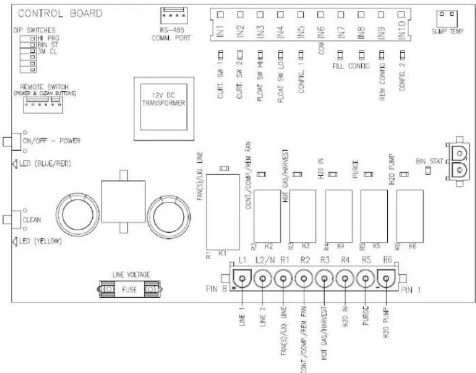
| Controller States | ||||||||||||||
| UNIT STATUS | OFF | FREEZE | FREEZE | FREEZE | FREEZE | FREEZE | FREEZE | FREEZE | HARVEST | HARVEST | HARVEST | OFF | FREEZE | |
| LED STATUS | RED LED(SOLID) | BLUE LED(SOLID) | BLUE LED(SOLID) | BLUE LED(SOLID) | BLUE LED(SOLID) | BLUE LED(SOLID) | BLUE LED(SOLID) | BLUE LED(SOLID) | BLUE LED(SOLID) | BLUE LED(SOLID) | BLUE LED(SOLID) | BLUE LED(SOLID) | BLUE LED(SOLID) | |
| COMPONENTS | - | FILL VERIFICATION | PRESSURE EQUALIZE | PRESSURE EQ.W/ COMPR. | PUMP DELAY | FREEZE | ANTI-SLUSH | FREEZE | HOT GAS/PURGE/FILL | TIMED FILL | HARVEST | CURT/STAT OPEN | FREEZE/WATER INLET ON/PRE-CHILL | FREEZE, RESTART/FUMP ON |
| FAN(S)(A&W)/LIQLINE SOLENO D (REM) | - | - | - | ON | ON | ON | ON | ON | ON REMOTE ONLY | ON REMOTE ONLY | ON REMOTE ONLY | - | ON | ON |
| CONTACTOR/COMPRESSOR/REM. COND.FAN | - | - | - | ON | ON | ON | ON | ON | ON | ON | ON | - | ON | ON |
| WATER PJMP | - | - | - | - | - | ON | - | ON | ON | - | - | - | - | ON |
| HOT GAS VALVE(S) | - | - | ON | ON | - | - | - | - | ON | ON | ON | - | - | - |
| HARVEST ASSIST(S) | ||||||||||||||
| WATER INLET VALVE | - | ON | - | - | - | - | - | - | ON | ON | - | - | ON | - |
| PURGE VALVE | - | - | - | - | - | - | - | - | ON | - | - | - | - | - |
| NOTE: | UNTIL HI FLOAT SW OPENS | COMPRESSOR PRESTART | COMPRESSOR START | PRE-CHILL EVAP PLATE | MIN FREEZE TIME | AT SUMP TEMP 34F, TURN OFF PUMP | LO FLOAT CLOSES OR MAX FREEZE | PURGE/HOT GAS/VALVES OPEN - HAA ENERGIZED | TIMED FILL | WAITING FOR CURT SW OR TIME | ICE RELEASED | CURT/STAT CLOSED AFTER DEBOUNCE UNIT RESTARTS | MIN. FREEZE TIME 5 MIN | |
| TIME(For reference only) | MAX 5 MIN | 5 SEC | 5 SEC | 30 SEC | 5 MIN OR MAX FREEZE | 20 SEC | 15 SEC | 20 SEC | APPROX 30 SECTO MAX HARVEST TIME | OPEN CURT/STAT AFTER DEBOUNCE | FILL TO HI FLOAT OPEN - 30 SEC PRE-CHILL START | LO FLOAT CLOSED OR MAX FREEZE | ||
Start-Up Procedure
Note: Before starting the machine, make sure the machine is level within 1/8 inch in all directions, the bin or dispenser leg height can be adjusted by rotating the leg foot.
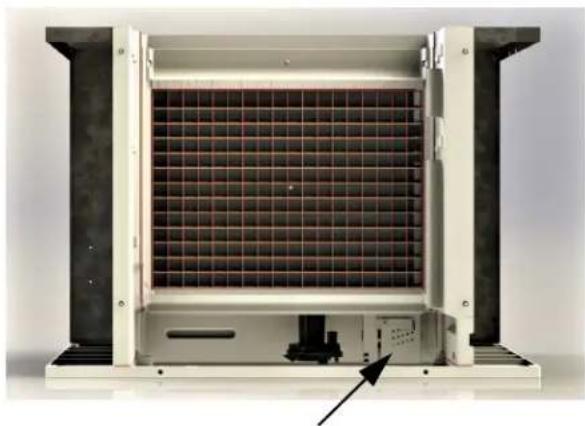
After verifying proper voltage, water supply, drains and breathable air space around the unit, press and quickly release the ON/OFF button behind the unit front panel. The indicator light will change from a solid red to solid blue in color.
Follow the sequence of operation described under "Operation of CIM Series Cuber" in this manual. Check operation of each component through the cycle as explained in this section.
natural_image
Interior view of a server rack unit with visible mesh and internal components (no text or symbols)Access to Water Level Adjustment
Bridge Thickness Adjustment
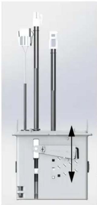
Once the unit has gone through a harvest cycle, verify the bridge thickness (3/16" thick for units less than 400 lbs. and 1/8" for 400 lbs. and above) across the middle of the ice slab on the second batch produced. The ice thickness can be changed on the Float Housing by turning the adjustment clockwise to decrease the bridge thickness and counter-clockwise to increase the bridge thickness. You will hear a "click" with each adjustment. it is recommended adjustments be made one or two "clicks" at a time.
natural_image
Technical diagram of a mechanical or electrical device with vertical and horizontal components, no visible text or symbolsLowers Float; increases bridge thickness
Raises Float; decreases bridge thickness
| Model Batch Weight | ||
| Half Cube Full | Cube | |
| CIM330/35 2.9 | -3.15 3.25-3.5 | |
| CIM430/630 4.9 | -5.15 5.5-5.8 | |
WARNING
Electrical shock and/or injury from moving parts inside this machine can cause serious injury. Disconnect electrical supply to machine prior to performing any adjustments or repairs.
Failure to perform the required maintenance at the frequency specified will void warranty coverage in the event of a related failure.
General Maintenance Procedure
To insure economical, trouble free operation of your machine; it is recommended that the following maintenance be performed every 6 months.
- Clean the ice-making section per the instructions below. Cleaning should be performed a minimum of every 6 months. Local water conditions may require that cleaning be performed more often.
- Check ice bridge thickness. See page 10 for proper thickness and adjustment procedure.
- Check water level in Sump. See page 10 for proper water level and adjustment procedure.
- Clean the condenser (air-cooled machines) to insure unobstructed air flow.
- Check for leaks of any kind: water, refrigerant, oil, etc.
- Check the bin control switch (if applicable) for proper adjustment.
- Check the Water Regulating Valve (water cooled machine) for proper adjustment by measuring the discharge pressure which should be adjusted to maintain 250 psi (17.01 bar/1.723 MPa). Adjust the water regulating valve as required. Water exiting the condenser should be between 100°F (38°C) and 110°F (43°C).
- Check all electrical connections.
- Oil the fan motor if the motor has an oil fitting. (Self contained air-cooled models only)
- Check the water filter (if applicable) and replace if dirty or restricted
- Inspect the evaporator water distribution tube to insure even distribution of water across the face of the evaporator.
- Clean Remote Condenser if applicable.
Cleaning Instruction for Ice-O-Matic CIM Series Ice Machines
Note: Proper cleaning of an ice machine requires two parts: descaling and sanitizing.
Descaling should be scheduled at a minimum of twice per year but no more than once per month.
Descaling dissolves the mineral deposits on the evaporator and other surfaces. It removes scale, calcium, lime scale and other mineral buildup. Ice-O-Matic requires a "nickel-safe" cleaner such as Nu-Calgon Nickel-Safe Ice Machine Cleaner or equivalent diluted per manufacturer's instructions.
Sanitizing should be performed after each descaling but no more than once per month.
Sanitizing disinfects the machine and removes microbial growth including mold and slime. Ice-O-Matic requires a “nickel-safe” sanitizer such as Nu-Calgon IMS-III or equivalent diluted per manufacturer’s instructions.
Please refer to www.iccomatic.com for approved chemical formulations and proper pH balance.
CAUTION: Do not mix cleaner (descaler) and sanitizer together.
Note: Electrical power will be ON when performing the following cleaning instructions.
- Remove all ice from storage means to prevent any contamination of ice in storage.
- Remove the front panel of the ice machine by loosening the two front panel screws with a Phillips head screwdriver. Lift panel to remove.
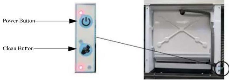
- Press and hold the POWER button for 3 seconds to initiate a harvest cycle (blue light will begin to flash for Manual Harvest mode). This ensures there is no ice on the plate and the water is emptied from the sump.
-
Once the ice machine has completed its harvest cycle, the POWER light will go to solid red (OFF mode).
-
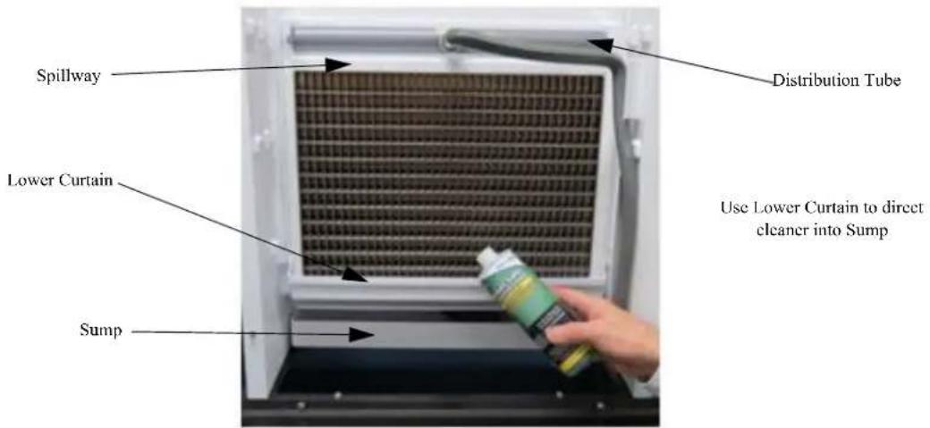
Remove the upper evaporator cover and leave the lower curtain.
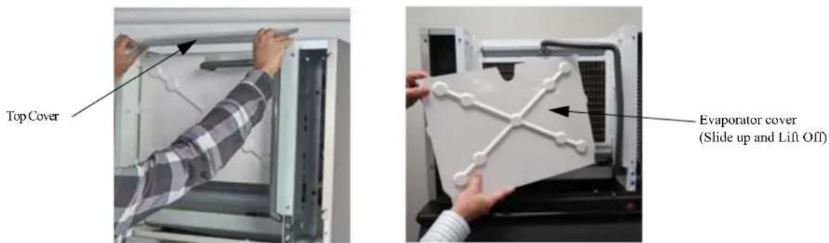
- Quick press the CLEAN button to start the process. Ice machine will show a solid red and flashing yellow light during the cleaning cycle.
- The machine will first verify that the sump is empty with the pump ON and the purge valve energized.
- When the sump is mostly empty, the machine will begin to fill the sump (about 30 seconds to a minute).
- The pump turns ON when the water fill reaches the proper fill level. Measure the appropriate amount of descaler according to the machine size and sump volume from chart below. Carefully pour the descaler into the sump using the lower curtain to prevent splash. Replace upper evaporator cover.
| Model | Sump Size (volume) Gallons (in liters) | Example: Nu-Calgon Nickel-Safe Ice Machine Cleaner Descaler Concentration Ratio 5 fl.oz. per 1 gal. | Example Nu-Calgon IMS-III Sanitizer Concentration Ratio 1.6 fl. oz. per 1 gal. |
| CIM0320/330 .9 (3.4) Add 4.5 fl. oz. Add 1.5 fl. oz. | |||
| CIM0430/520/530/630 1.2 (4.5) Add 6 fl. oz. Add 2 fl. oz. |
- The machine will remain in the WASH cycle for 15 minutes (cycle may be shortened after a minimum of 5 minutes if CLEAN button is depressed).
- After WASH time, the machine will PURGE and re-fill with the water pump ON.
- The machine will RINSE (less than one minute) then repeat PURGE/FILL/RINSE multiple times.
- The machine will end the cleaning cycle with a mostly empty sump and a solid red and yellow light.
- Quick press the CLEAN button to return to OFF mode.
- Remove the upper evaporator cover and lower evaporator curtain. Inspect the evaporator, water spillway, water distributor, evaporator cover, evaporator curtain and any splash surfaces to verify that all mineral residue has been removed. Remove any residual minerals with a clean soft cloth.
- If a full clean of water components is required, this can be done by referring to the service manual for water system component breakdown. This is recommended to be done by a qualified service agent.
- Re-assemble all ice machine water system components in reverse order.
- Sanitizing the ice machine is recommended after descaling. Repeat the process with sanitizer at correct ratio.
- It is recommended to clean (descale and sanitize) the storage means after cleaning the ice machine.
- Quick press the POWER button to return the ice machine to the ice making cycle.
- Replace the front panel and tighten the two panel screws with a Phillips screwdriver.
Chemicals for Descaling and Sanitizing
It is important to use solutions that do not harm the ice machine. Never use cleaning or sanitizing solutions that contain Nitric Acid, Sulfuric Acid, Hydrochloric Acid, Carbolic Acid, Acetic Acid, diluted Acetic Acid or non-food-grade vinegar (concentration of acetic acid greater than 6% and does not contain enzymes created in processing) or any chlorine-based solution such as bleach, chlorine dioxide or any type of salts such as potassium chloride (potassium salts) or sodium chloride. Check the label or the manufacturer's Material Safety Data Sheet (MSDS) to be sure. These chemicals can attack the surface of the evaporator as well as other metal components causing corrosion and flaking.
Please refer to www.iccomatic.com for approved chemical formulations and proper pH balance.
Cleaning Stainless Steel and Aluminum
Commercial grades of stainless steel and aluminum are susceptible to rusting or corrosion if not properly maintained. It is important that you properly care for the stainless steel and aluminum surfaces of your ice machine and bin to avoid the possibility of rust or corrosion.
Use the following recommended guidelines for keeping your machine looking like new:
- Clean the stainless steel and aluminum thoroughly once a week. Clean frequently to avoid build-up of hard, stubborn stains. Hard water stains left to sit can weaken the metals corrosion resistance and lead to rust or corrosion. Use a nonabrasive cloth or sponge, working with, not across, the grain.
- Do not use abrasive tools to clean the metal surface. Do not use steel wool, abrasive sponge pads, wire brushes or scrapers to clean the metal.
- Do not use cleaners that use chlorine or chlorides. Do not use chlorine bleach products to clean the metal surfaces. Chlorides break down the metals protective layer.
- Rinse with clean water. If chlorinated cleansers are used, you must thoroughly rinse the surface with clean water and wipe dry immediately.
- Use the right cleaning agent. The table below lists the recommended cleaning agents for common metal cleaning problems.
| Cleaning Activity Cleaning Agent Method of Application | ||
| Routine Cleaning | Mild dish soap, ammonia, glass cleaner, or mild detergent with water. Household kitchen cleaning chemicals approved for metal surfaces. | Apply with clean cloth or sponge. Rinse with clean water and wipe dry. |
| Removing grease or fatty acids | Oven cleaners | Apply generously; allow to stand for 15-20 minutes. Rinse with clean water. Repeat as required. |
| Removing hard water spots and scale | Vinegar | Swab or wipe with clean cloth. Rinse with water and wipe dry. |
Winterizing Procedures
IMPORTANT: Whenever the ice machine is taken out of operation during the winter months, the procedure below must be performed. Failure to do so may cause serious damage and will void all warranties.
-
Turn off water to machine.
-
Make sure all ice is off of the evaporator(s). If ice is being made, initiate harvest by pressing the Power Button for approximately 3 seconds. The unit will shut off automatically following the harvest.
-
Disconnect the tubing between the water pump discharge and water distribution tube and drain any water.
-
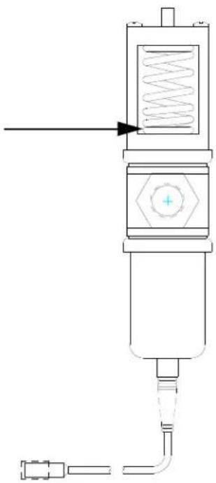
On water cooled machines, hold the water regulating valve open by prying upward on the water valve spring with a screwdriver while using compressed air to blow all the water out of the condenser.
natural_image
Pure mechanical diagram of a vertical actuator or pressure vessel with no text, numbers, or symbols- Remove all of the ice in the storage bin and discard.

- ELEVATION SERIES CUBE ICE MAKER
- Installation Guide and Owner's Manual
- Energy Efficiency
- Freight Claims
- Inspect Promptly
- Concealed Loss or Damage
- Visible Loss or Damage
- FILE CLAIMS WITHOUT DELAY
- DO NOT RETURN DAMAGED GOODS TO ICE-O-MATIC
- How to use this Manual
- WARNING
- CAUTION
- Ice-O-Matic Warranty
- Installation Guidelines
- Water Filtration/Treatment
- Ambient Operating Temperature
- Incoming Water Supply
- Drains
- Clearance Requirements
- Stacking
- Dispenser Application
- Electrical Specifications
- Units are not approved for GFI outlets.
- Adjustments
- Remote Condenser Installation
- Location Limits
- Roof Attachment
- Calculation Formula
- Pre-charged Line Set Routing
- Remote Condenser Location
- Equivalent Run Calculation Examples
- Formula for maximum equivalent run:
- Electrical and Plumbing Requirements CIM SERIES Common Connections
- Air Cooled
- Water/Remote Cooled
- Operation of the CIM Series Cuber
- Freeze Cycle
- Harvest Cycle
- Start-Up Procedure
- Bridge Thickness Adjustment
- General Maintenance Procedure
- Cleaning Instruction for Ice-O-Matic CIM Series Ice Machines
- Chemicals for Descaling and Sanitizing
- Cleaning Stainless Steel and Aluminum
- Winterizing Procedures
Brand : Ice-O-Matic
Model : CIM0430FA
Category : Ice machine