
skyBeacon STC - Balise aéronautique uAvionix - Free user manual and instructions
Find the device manual for free skyBeacon STC uAvionix in PDF.


| Product Type | Wingtip position light with integrated ADS-B Out (UAT), strobe light, and anti-collision light |
| Brand | uAvionix |
| Model | skyBeacon STC (UAV-1001856-002) |
| Dimensions (W x H x D) | 3.665 in (93.10 mm) x 4.504 in (114.4 mm) x 1.192 in (30.28 mm) |
| Weight | 3.5 oz (100 g) |
| Input Voltage Range | 9 to 33 VDC |
| Current Consumption (14V) | 0.5 A max |
| Current Consumption (28V) | 0.25 A max |
| Operating Temperature Range | -45°C to +70°C |
| Maximum Pressure Altitude | 18,000 ft (UAT usage restricted below 18,000 ft MSL per §91.225) |
| Certifications | TSO-C145d, TSO-C154c, TSO-C30c, TSO-C96a, TSO-C88b; FAA STC |
| Primary Functions | ADS-B Out (UAT 978 MHz), position light (red), anti-collision strobe light, altitude reporting via connected transponder |
| Mounting Location | Wingtip, forward left position light hole |
| Mounting Hardware | Three 6-32 screws with O-ring seals (torque 8-10 in-lbs) |
| Wiring Connections | Red (nav light power 14/28V), Yellow (strobe light power 14/28V), Black (aircraft ground) |
| Configuration Interface | iOS/Android app via Wi-Fi; refer to User and Installation Guide UAV-1001421-001 |
| Maintenance | No scheduled maintenance; periodic inspection of O-rings and screws; keep lens clean |
| Safety Warnings | Not for use on aircraft with TCAS/ACAS; not compatible with SatCom; keep at least 3 ft from transponder antenna; do not connect yellow wire to high-voltage anti-collision supply |
| Repairability / Spare Parts | Spare O-rings (P/N UAV-1002038-001), mounting screws (various lengths), crimp splices (UAV-1001487-001); unit is not user-serviceable beyond replacement |
| Included in Box | skyBeacon unit, mounting screws, O-rings, crimp splices; fairing (for specific Cessna models if applicable) |
Frequently Asked Questions - skyBeacon STC uAvionix
User questions about skyBeacon STC uAvionix
0 question about this device. Answer the ones you know or ask your own.
Ask a new question about this device
Download the instructions for your Balise aéronautique in PDF format for free! Find your manual skyBeacon STC - uAvionix and take your electronic device back in hand. On this page are published all the documents necessary for the use of your device. skyBeacon STC by uAvionix.
USER MANUAL skyBeacon STC uAvionix
natural_image
Cross-sectional view of a mechanical device showing internal components and housing (no text or symbols visible)FAA APPROVED
UAV-1002305-001
Rev C
NOV 27 2018 AIR-7C2 MC CHICAGO ACO BRANCH C & A DIVISION
© 2018 uAvionix Corporation. All rights reserved.
Except as expressly provided herein, no part of this guide may be reproduced, transmitted, disseminated, downloaded or stored in any storage medium, for any purpose without the express written permission of uAvionix. uAvionix grants permissions to download a single copy of this guide onto an electronic storage medium to be viewed for personal use, provided that the complete text of this copyright notice is retained. Unauthorized commercial distribution of this manual or any revision hereto is strictly prohibited.
uAvionix ® and Ping ® are registered trademarks of uAvionix Corporation and may not be used without express permission of uAvionix.
skyBeacon, Continuous Calibration, Power Transcoder, Echo Installer, and Ping Installer are trademarks of uAvionix Corporation and may not be used without express permission of uAvionix.
skyBeacon technologies are patent pending.
1 Revision History
| Revision | Date | Comments |
| A | 9/10/2018 | Initial release |
| B | 10/18/2018 | Update part number and system limitations |
| C | 11/4/2018 | Update transponder limitation to include altitude source |
2 Warnings / Disclaimers
uAvionix is not liable for damages arising from the use or misuse of this product.
This equipment is classified by the United States Department of Commerce's Bureau of Industry and Security (BIS) as Export Control Classification Number (ECCN) 7A994.
These items are controlled by the U.S. Government and authorized for export only to the country of ultimate destination for use by the ultimate consignee or end-user(s) herein identified. They may not be resold, transferred, or otherwise disposed of, to any other country or to any person other than the authorized ultimate consignee or end-user(s), either in their original form or after being incorporated into other items, without first obtaining approval from the U.S. government or as otherwise authorized by U.S. law and regulations.
3 Table of Contents
1 Revision History....3
2 Warnings / Disclaimers....4
3 Table of Contents ....5
4 System Information....6
4.1 Certification....6
4.2 TSO Authorization....7
4.3 System Limitations....8
5 System Specifications....9
5.1 Physical Specifications 9
5.2 System Interfaces....10
6 Installation 11
6.1 Unpacking and Inspecting....11
6.2 Mounting....11
6.3 Unit Installation Overview....12
6.4 Mounting Dimensions 13
6.5 Mounting Procedure on Wingtips 14
6.6 Mounting Procedure on Wingtips with Adaptive Fairing ..... 16
6.6.1 Fairing Configuration 18
6.7 skyBeacon System Configuration 18
6.8 Flight Checks....18
7 Support....19
4 System Information
4.1 Certification
This installation manual provides mechanical and electrical information necessary to install skyBeacon. The content of this manual assumes use by competent and qualified personnel using standard maintenance procedures in accordance with Title 14 of the Code of Federal Regulation and other related accepted procedures.
Those installing this article on an aircraft listed on the Approved Models List shall verify the compatibility of existing STCs with this STC prior to returning the aircraft to service.
4.2 TSO Authorization
| Function | TSO/RTCA/SAE | Class/Type |
| Airborne Navigation Sensor Using the Global Position System (GPS) Augmented by the Satellite Based Augmentation System (SBAS) | TSO-C145d INCOMP RTCA/DO-229D | Beta 1 |
| Universal Access Transmitter (UAT) Automatic Dependent Surveillance-Broadcast (ADS-B) Equipment Operating on Frequency of 978MHz | TSO-C154c RTCA/DO-260B | B1S |
| Position Light (Red) | TSO-C30c SAE/AS8037 | Type I |
| Anti-Collision Light | TSO-C96a SAE/AS8017D | Class II |
| Automatic Pressure Altitude Reporting Code-Generating Equipment | TSO-C88b SAE/AS8003 |
4.3 System Limitations
Installation
This article meets the minimum performance and quality control standards required by a technical standard order (TSO) and when installed on aircraft approved on the AML can be approved for return to service after installation.
If you are installing this article on or in a specific type or class of aircraft, not listed on the AML you must obtain separate approval for installation.
TCAS/ACAS system
skyBeacon should not be installed if the aircraft has an active TCAS/ACAS system.
SatCom
The skyBeacon GPS has not been demonstrated as compatible with SatCom equipment and should not be installed on SatCom equipped aircraft.
Transponder
A companion altitude-reporting transponder is required to be installed for 14 CFR 91.225 and 91.227 compliance, unless installed on an aircraft excepted from the requirements of 14 CFR 91.215 and 91.225.
The transponder's altitude source must comply with TSO-C10(), TSO-C106() or TSO-C88() and meet the requirements of 14 CFR 91.217.
Transponder antenna
skyBeacon should be installed at least 3 feet from any operating transponder antenna.
5 System Specifications
5.1 Physical Specifications
| Characteristics | Specifications |
| Width | 3.665 in (93.10 mm) |
| Height | 4.504 in (114.4 mm) |
| Depth | 1.192 in (30.28 mm) |
| Weight | 3.5oz (100 grams) |
| Operating Temperature Range | -45°C to +70°C |
| Maximum Pressure Altitude [1] | 18,000 ft |
| Input Voltage Range | 9 to 33 VDC |
| 14V Current | 0.5A Max |
| 28V Current | 0.25A Max |
[1] UAT usage is restricted to below 18,000 feet MSL ( §91.225 ).
![6.71 [1.192] 30.28 3.665 93.10 4.504 114.40 uAvioni](/content/2026/05/934062/images/fcee6cf45f0eb517dc3f5dd2676b86924d2cde14b52b0244b580b42c264969be.jpg)
5.2 System Interfaces
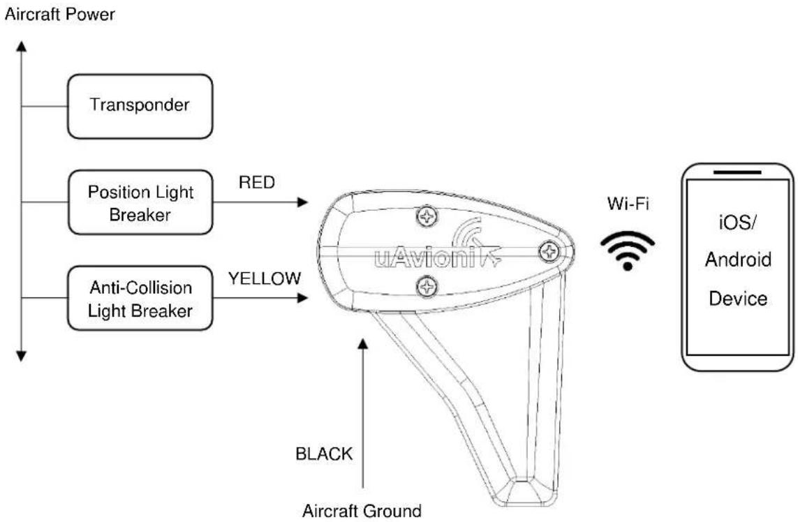
flowchart
graph TD
    A["Aircraft Power"] --> B["Transponder"]
    A --> C["Position Light Breaker"]
    A --> D["Anti-Collision Light Breaker"]
    C --> E["RED"]
    D --> F["YELLOW"]
    G["Aircraft Ground"] --> H["BLACK"]
    I["uAvioni Device"] --> J["Wi-Fi"]
    K["iOS/Android Device"] --> L["Wi-Fi"]
6 Installation
6.1 Unpacking and Inspecting
Carefully unpack the device and make a visual inspection of the unit for evidence of any damage incurred during shipment. If the unit is damaged, notify the shipping company to file a claim for the damage. To justify your claim, save the original shipping container and all packing materials.
6.2 Mounting
skyBeacon is a wingtip, forward, left position light. The assembly should be mounted as far outboard on the aircraft as practical, parallel to the vertical and horizontal centerlines of the aircraft. Ensure that when mounted, the fin and top of the assembly are free from obstructions.
Note: Installation of the skyBeacon must be in accordance with AC 43-13.2B, Chapter 1
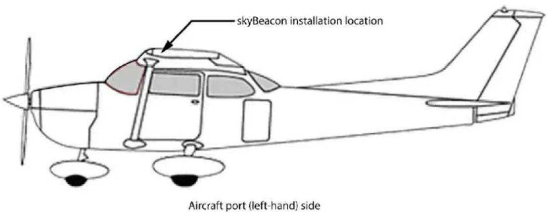
6.3 Unit Installation Overview
skyBeacon is mounted with three 6-32 screws to the existing holes and nut plates in the end of the wing. Two O-rings per screw must be used between the screw and skyBeacon assembly.

6.4 Mounting Dimensions
![WING SURFACE [ .642in ] 16.30mm [ 1.740in ] 44.20mm [ .500in ] 12.70mm MIN [ 1.000in ] 25.40mm 3x 6-32 NUT PLATES](/content/2026/05/934062/images/6c370749f1c079a4fd286767b00a0b9db11877f5a502fd36ef80dfd614f134be.jpg)
6.5 Mounting Procedure on Wingtips
For aircraft where the skyBeacon mounts to the mounting holes as shown in Section 6.4, and the wingtip configuration is as shown in the figure below, install the skyBeacon per the instructions and with hardware noted below.

"CLEAN INSTALL" REQUIRES NO ADDITIONAL FAIRING/ADAPTERS
| Item | Description | Qty | P/N |
| 1 | skyBeacon | 1 | UAV-1001856-002 |
| 2 | O-ring Seals (1mm x 5mm EPDM) | 6 | UAV-1002038-001 |
| 3 | Mounting Screw (6-32 x 1.25") | 3 | UAV-1001459-001 |
| Mounting Screw (6-32 x 1.5") | UAV-1001459-002 | ||
| Mounting Screw (6-32 x 1.75") | UAV-1001459-003 | ||
| 4 | Nav Light Power (Red) 14/28V | Ref | |
| 5 | Strobe Light Power (Yellow) 14/28V | Ref | |
| 6 | Aircraft Ground (Black) | Ref | |
| 7 | Wingtip | Ref | |
| 8 | Aircraft Nav Light Power 14/28V | Ref | |
| 9 | Aircraft Strobe Light Power 14/28V | Ref | |
| 10 | Aircraft Ground | Ref | |
| 14 | Mounting Hole with 6-32 Thread with locking feature | 3 | |
| 15 | Crimp type Wire Splices 18-22 AWG (not shown) | 3 | UAV-1001487-001 |
1) Remove fasteners retaining the existing position and strobe lights from wingtip.
UAV-1002305-001 14
Rev C
Access wiring to disconnect the existing position and strobe lights. Prepare the wire ends (Items 8, 9, 10) per AC 43-13 for crimp type wire splices.
Note: If aircraft is not equipped for wing strobe functionality, stow the skyBeacon yellow wire (Item 5) per AC 43-13.
2) Splice wires using (Item 15) environmental splices or equivalent.

WARNING: DO NOT connect the skyBeacon yellow wire (Item 5) to a high voltage anti-collision power supply. Only connect the yellow wire directly to 14/28V aircraft power or stow per AC 43-13.
3) Attach the skyBeacon (Item 1) to the wing tip as follows:
a) Position skyBeacon onto the wingtip and confirm alignment with existing mounting holes (Item 14) as shown in Section 6.4.
b) Install 2 O-ring seals (Item 2) onto each screw (Item 3).
Note- the O-ring nearest the head of the screw must be replaced if the screw is tightened and subsequently removed.
c) Use the appropriate length mounting screws (Item 3) to attach skyBeacon to the wingtip. Tighten screws to 8-10 in-lbs.
4) Apply power to the Position light and confirm position light operation.
5) If equipped apply power to strobe light and confirm strobe light operation.
6) Install placard as defined in AFM Supplement document UAV-1002111-001 Section 2.2.
7) Go to Section 6.7 for skyBeacon setup.
6.6 Mounting Procedure on Wingtips with Adaptive Fairing
For aircraft that attach to the mounting holes as shown in Section 6.4 but use a fairing to cover a portion of the position lights, an additional adaptive fairing may be used to improve or refine fit of the installation. If desired, install the skyBeacon utilizing a fairing identified in section 6.6.1 per the instructions and with hardware noted below.
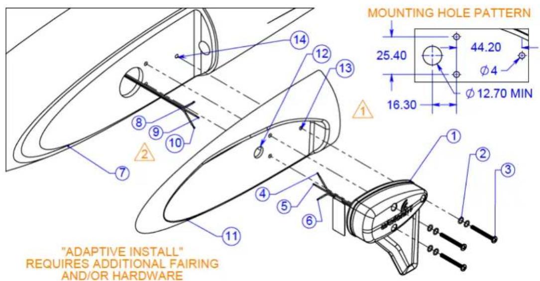
| Item | Description | Qty | P/N |
| 1 | skyBeacon | 1 | UAV-1001856-002 |
| 2 | O-ring Seals (1mm x 5mm EPDM) | 6 | UAV-1002038-001 |
| 3 | Mounting Screws | 3 | |
| Mounting Screw (6-32 x 1.25") | AR | UAV-1001459-001 | |
| Mounting Screw (6-32 x 1.5") | AR | UAV-1001459-002 | |
| Mounting Screw (6-32 x 1.75") | AR | UAV-1001459-003 | |
| 4 | Nav Light Power (Red) 14/28V | Ref | |
| 5 | Strobe Light Power (Yellow) 14/28V | Ref | |
| 6 | Aircraft Ground (Black) | Ref | |
| 7 | Wingtip | Ref | |
| 8 | Aircraft Nav Light Power 14/28V | Ref | |
| 9 | Aircraft Strobe Light Power 14/28V | Ref | |
| 10 | Aircraft Ground | Ref | |
| 11 | skyBeacon adaptor fairing | 1 | See Section 6.6.1 |
| 12 | Hole for wire pass through | Ref |
UAV-1002305-001 16
Rev C
| Item | Description | Qty | P/N |
| 13 | Hole for mounting | Ref | |
| 14 | Mounting Hole with 6-32 Thread with locking feature | 3 | |
| 15 | Crimp type Wire Splices 18-22 AWG (not shown) | 3 | UAV-1001487-001 |
1) Remove fasteners retaining the existing fairing, position and strobe lights from wingtip.
2) Access wiring to disconnect the existing position and strobe lights. Prepare the aircraft wire ends (Items 8, 9, 10) per AC 43-13 for crimp type wire splices.
3) Fit the skyBeacon fairing to the wingtip.

Modify the skyBeacon fairing as needed for best fit to existing wingtip per AC 43-13.
4) Locate mounting holes (Item 13) and wire pass through holes (Item 12) to match the wingtip.
5) Drill clearance hole for #6 screws through the skyBeacon fairing (Item 11) for the mounting holes and a 0.5-1" hole for the wire pass through.
6) Splice wires using (Item 15) environmental splices or equivalent.
Note: If aircraft is not equipped for wing strobe functionality, stow the skyBeacon yellow wire (Item 5) per AC 43-13.

WARNING: DO NOT connect the skyBeacon yellow wire (Item 5) to a high voltage anti-collision power supply. Only connect the yellow wire directly to 14/28V aircraft power or stow per AC 43-13.
7) Attach the skyBeacon (Item 1) to the wing tip as follows
a) Position skyBeacon and skyBeacon fairing onto the wingtip and confirm alignment with existing mounting holes (Item 14).
b) Install 2 O-ring seals (Item 2) onto each screw (Item 3).
Note: the O-ring nearest the head of the screw must be replaced if the screw is tightened and subsequently removed.
UAV-1002305-001 17
Rev C
c) Use appropriate length mounting screws (Item 3) to attach skyBeacon to the wingtip fairing. Tighten screws to 8-10 in-lbs.
8) Apply power to the Position light and confirm position light operation
9) If equipped apply power to strobe light and confirm strobe light operation
10) Install placard as defined in AFM Supplement document UAV-1002111-001 Section 2.2.
11) Go to Section 6.7 for skyBeacon setup.
6.6.1 Fairing Configuration
The fairing required for each model aircraft is as follows:
| Make | Model | P/N |
| Cessna | 150L, 150M, 152, 185E, 180H, 182N | UAV-1002301-001 |
| Cessna | 172L, 172M, 172N, 172Q, 172R, 172RG, 182Q, 182R, 182S, 182T, T182T, R182, 180J, 180K, A185K, U206G, TU206F, TU206G, 177B, 177RG | UAV-1002302-001 |
6.7 skyBeacon System Configuration
Follow instructions provided in the "skyBeacon User and Installation Guide" UAV-1001421-001 Section 10 to configure the system and perform post-installation checks.
6.8 Flight Checks
If the owner desires to further confirm the skyBeacon was installed and configured properly, perform a flight within ADS-B airspace coverage and request a FAA flight test compliance report.
To perform an ADS-B Out flight check requires flying in airspace where ADS-B coverage exists. In some areas in the country, you may need to be
UAV-1002305-001 18
Rev C
at a higher altitude to ensure coverage. Use of a portable ADS-B In with an EFB (or equivalent) can provide the pilot an indication that the airplane is within ADS-B coverage.
If a dedicated flight is desired, perform a take-off, climb, simple maneuvers (standard rate turns around a point for example), descend and land. Do not perform any aerobatic maneuvers. Further guidance for flight test procedures can be found in AC 20-165B.
Upon completion of the flight, request an ADS-B Aircraft Operation Compliance Report (ACR) at the Public ADS-B Performance Report Request Internet site:
https://adsbperformance.faa.gov/PAPRRequest.aspx
7 Support
For additional questions or support please visit:
http://www.uavionix.com/support/


- Revision History
- Warnings / Disclaimers
- Table of Contents
- System Information
- Certification
- System Limitations
- Installation
- TCAS/ACAS system
- SatCom
- Transponder
- Transponder antenna
- System Specifications
- Physical Specifications
- System Interfaces
- Installation
- Unpacking and Inspecting
- Mounting
- Unit Installation Overview
- Mounting Procedure on Wingtips
- Mounting Procedure on Wingtips with Adaptive Fairing
- Fairing Configuration
- skyBeacon System Configuration
- Flight Checks
- Support
Brand : uAvionix
Model : skyBeacon STC
Category : Balise aéronautique