
TCR90BK - Range hood Technika - Free user manual and instructions
Find the device manual for free TCR90BK Technika in PDF.


| Product Type | Canopy Range Hood |
| Brand | Technika |
| Model | TCR90BK |
| Width | 900 mm |
| Installation Type | Ducted |
| Minimum Distance from Cooktop | 600 mm (650–750 mm recommended) |
| Power Supply | 220–240 V, 50 Hz |
| Electrical Connection | 10 A, 3-pin plug, Class I (earthing required) |
| Motor Speeds | 4 speeds (auto reduces from speed 4 to 3 after 2 minutes) |
| Timer | 15-minute auto shut-off |
| Lighting | LED lamps (replaceable spare part) |
| Filter Type | Aluminum grease filters (washable) |
| Filter Cleaning | Every 2 months; hand wash with mild detergent or dishwasher |
| Control Type | Electronic push buttons with digital display |
| Safety Features | High temperature safety device; overheat auto shut-off |
| Air Discharge | Not to be discharged into flue used for gas or other fuel appliances |
| Compliance | AS/NZS 5601; local regulations for exhaust air |
Frequently Asked Questions - TCR90BK Technika
User questions about TCR90BK Technika
0 question about this device. Answer the ones you know or ask your own.
Ask a new question about this device
Download the instructions for your Range hood in PDF format for free! Find your manual TCR90BK - Technika and take your electronic device back in hand. On this page are published all the documents necessary for the use of your device. TCR90BK by Technika.
USER MANUAL TCR90BK Technika
Instructions for Use and Installation
60cm Canopy Rangehood TCR60BK
90cm Canopy Rangehood TCR90BK
For Your Safety
Safety Precautions....3
Before Connecting 3
Warnings 4
Use and Care
Use and Care 6
LED Lamp 6
Controls 7
Cleaning your Rangehood 8
Troubleshooting 9
Disposal 10
Installation
Electrical Connection 11
Instructions for Installation 12
Fixing to the Wall 13
Fixing the Decorative Telescopic Flue....15
Dimensions....16
For Your Safety
Carefully read the following important information regarding installation safety and maintenance. Keep this information booklet accessible for future reference.
The appliance has been designed for use in a Ducted installation, see Fig.1.

natural_image
Pure mechanical diagram showing fluid flow through a channel with no text or symbolsSafety Precautions
Take care when the Range Hood is operating simultaneously with an open fireplace or burner that depend on natural ventilation as the Range Hood removes air from the room, which a burner or fireplace may need for combustion.
Provide adequate ventilation for safe operation of the Range Hood. Follow any local laws that apply to external air evacuation.
Before connecting to the electricity network:
Look at the data plate (located inside the appliance) to ascertain that the voltage and power correspond to the available power supply and the power outlet is suitable. If in doubt ask a qualified electrician.
If the appliance is used intensively for a long period of time, you may need to opening a window to improve airflow.

WARNINGS!
- Do not check the status of the filters while the Range Hood is operating.
- Do not touch bulbs or adjacent areas, during or straight after use.
- CAUTION: Accessible parts may become hot when used with cooking appliances.
- Do not flambé under the Range Hood.
- Avoid free flame, as it is damaging to the filters and can cause fire hazard.
- Constantly check food frying, overheated oil may become a fire hazard.
- Disconnect the electrical plug prior to any maintenance.
- This appliance is not intended for use by persons (including children) with reduced physical, sensory or mental capabilities, or lack of experience and knowledge, unless they have been given supervision or instruction concerning use of the appliance by a person responsible for their safety.
- Children should be supervised to ensure that they do not play with the appliance.
- There shall be adequate ventilation in the room when the Range Hood is used at the same time as appliances burning gas or other fuels.
- There is a fire risk if cleaning is not carried out in accordance with the instructions.
- WARNING: DO NOT penetrate any screws into the range hood as this may result in electrical hazards.
- WARNING: Failure to install the screws or fixing device in accordance with these instructions may result in electrical hazards.

WARNINGS!
- If the supply cord is damaged, it must be replaced by the manufacturer, its service agent or similarly qualified persons in order to avoid a hazard.
- The air must not be discharged into a flue that is used for exhausting fumes from appliances burning gas or other fuels.
- The minimum distance between the cooktop hob and the lowest part of the range hood shall be at least 60cm. If the instructions for installation of the gas hob specify a greater distance, this has to be taken into account.
- Regulation concerning the discharge of air has to be fulfilled.
THE MANUFACTURER DECLINES ALL RESPONSIBILITY FOR DAMAGES CAUSED BY BREACHING THE ABOVE WARNINGS.
Use and Care
It is recommended to start the Range Hood prior to commencing to cook and leave the Range Hood in operation for 15 minutes after cooking is finished in order to completely eliminate cooking vapours and odours.
To ensure the Range Hood continues to operate effectively, regular maintenance and cleaning is required. Clean the fan and other surfaces of the Range Hood regularly using a cloth moistened with warm water or non abrasive liquid detergent.
LED Lamps
LED lamps are a spare part and are not repairable, LED lamps can be easily removed and replacements installed, note the plug and socket connection. Please contact Technika Spare Parts department for replacement lamps. (Fig. 2&3)

natural_image
Simple line drawing of a tool interacting with a circular component and a plate, labeled Fig.2 (no text or symbols on the diagram itself)
natural_image
Diagram of a mechanical or electrical component with labeled parts and directional arrows, no readable text or symbols present.Controls
FUNCTION KEYS: (Fig.4)
$$ \begin{array}{l} A = O N / O F F \ B = 1 5 \text { MIN STOP TIMER } \ C = S P E E D D O W N - \ D = D I G I T A L D I S P L A Y S C R E E N \ E = S P E E D U P + \ F = F A N \ G = L I G H T \ \end{array} $$
Fig. 4

flowchart
graph TD
    A["Input"] --> B["A"]
    C["Input"] --> D["B"]
    E["Input"] --> F["F"]
    G["Input"] --> H["G"]
    I["Input"] --> J["C"]
    K["Input"] --> L["D"]
    M["Input"] --> N["E"]
    O["Input"] --> P["F"]
    Q["Input"] --> R["G"]
- Turn the rangehood on using button 'A'. The fan will automatically start on speed 1.
- Use button 'E' to select higher speeds and button 'C' to select lower speeds.
- When you select speed 4, the fan will automatically turn down to speed 3 after 2 minutes.
- Use the light button 'G' to turn the lights on and off.
- When you use the timer button 'B' the symbol will flash and the fan and lights will turn off after 15mins.
Cleaning your rangehood
The proper function of the rangehood requires regular maintenance operations.
The anti-grease filters capture the grease particles suspended in the air, and are therefore subject to clogging according to the frequency of the use of the appliance.
In order to prevent fire hazard, it is recommendable to clean the filter at a minimum of every 2 months by carrying out the following instructions:
- Remove the filters from the cooker hood and wash them in a solution of water and neutral liquid detergent, leaving to soak.
- Rinse thoroughly with warm water and leave to dry.
- The filters may also be washed in the dishwasher.
Clean the fan and other surfaces of the cooker hood regularly using a cloth moistened with denatured alcohol or non abrasive liquid detergent.
Keep motor and other parts free from water as this will cause damage to the appliance.
Troubleshooting
| Problem | Possible reason | Solution |
| Hood doesn’t work | No electricity supply | Check the plug is connected |
| Check that the main switch/circuit breaker/safety switch is turned on | ||
| Poor airflow | Aluminum grease filters clogged | Clean the filters and replace when dry |
| Motor running but no air flow | Butterfly valve jammed | Contact service department |
| Motor turns off after a few minutes | High temperature safety device activated | The kitchen is not sufficiently ventilated |
| The hood is installed too near to the cooktop | The hood must be at least 600mm from the top of the cooktop | |
| Oil dripping onto stove | Aluminum grease filter saturated | Wash the aluminum grease filters |
| Whirring sound | Something in contact with fan blade | Contact service department |
Disposal

By ensuring this product is disposed of correctly, you will help prevent potential negative consequences for the environment and human health, which could otherwise be caused by inappropriate waste handling of this product.
The symbol on the product indicates that this product may not be treated as household waste. Instead it shall be handed over to the applicable collection point for the recycling of electrical and electronic equipment.
Disposal must be carried out in accordance with local environmental regulations for waste disposal.
For more detailed information about treatment, recovery and recycling of this product, please contact your local city council office.
Assembly and electrical connections must be carried out by authorised personnel.
Electrical Connection
The Range Hood is fitted with a power cord and 3 pin plug. Install the Range Hood so that the plug is easily accessible. Plug the 3-pin plug into a properly earthed, 10A general purpose power outlet.
If the supply cord is damaged, it must be replaced by the manufacturer or its service agent or a similarly qualified person in order to avoid a hazard.
The appliance has been manufactured as a class I, therefore earth cable is necessary.
The connection to the mains is carried out as follows:
| IEC227 North America | ||
| L = Live Brown Black | ||
| N = Neutral Blue White | ||
| E = Earth Green/Yellow Green |
If not provided, connect a plug for the electrical load indicated on the description label. Where a plug is provided, the cooker hood must be installed so that the plug is easily accessible after installation.
An omnipolar switch with a minimum aperture of 3mm between contacts, in line with the electrical load and local standards, must be placed between the appliance and the network in the case of direct connection to the electrical network.
Instructions for Installation
Install Range Hoods in accordance with the manufacturer's instructions.
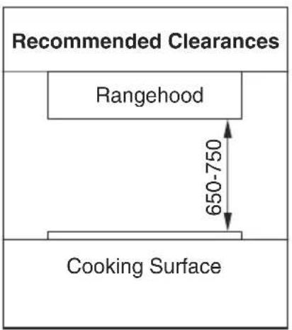
For optimum performance, Technika recommends that all Range Hood clearances be a minimum of 650mm to a maximum of 750mm, between the top of the cooking surface to the underside of the Range Hood. The distance may be reduced to 600mm to align with AS/NZS 5601.
WARNING: DO NOT penetrate any screws into the range hood as this may result in electrical hazards.
WARNING: Failure to install the screws or fixing device in accordance with these instructions may result in electrical hazards.
If a connection flue composed of two parts is used, the upper part must be placed outside the lower part.
Exhaust air must not be discharged into a flue which is used for exhausting fumes from appliances burning gas or other fuels. Installation must comply with any local regulations concerning the discharge of exhaust air.
Before proceeding with the assembly, remove the anti-grease filter so that the unit is easier to handle. Prepare the hole in the ceiling or wall for the evacuation of the air.
Fixing to the Wall
Ensure the fixings used for this range hood are suitable.
Check the area where the range hood is to be fitted, to ensure that it is structurally sound and will support the weight of the appliance. Do not install directly onto plaster board using 'Wall mates' or other similar anchors.
The range hood must be fixed into studs or nozzgins in the wall to ensure it is secure and minimize vibration in the wall.
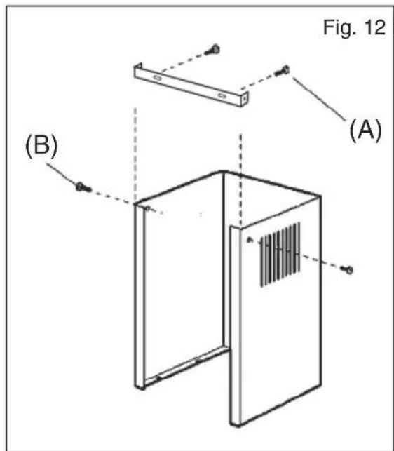
Fix the range hood to the wall and align it in a horizontal position to the wall units. Once the range hood has been adjusted, fix it to the wall using the screws supplied (See A in Fig.12).
For various installation types, use screws and screw anchors suited to the type of wall (e.g. reinforced concrete, plasterboard, etc.). If the screws and screw anchors are provided with the product, check that they are suitable for the type of wall on which the hood is to be fixed.
-
Mark a vertical centre line on the wall from the ceiling to the lower edge of the range hood.
-
Mark the contour of the attachment area.
-
Mark and drill the positions for the fixing screws.
-
Screw on the fixing bracket for the flue duct.


Installation
- Screw on brackets for the range hood hand-tight. Do not firmly tighten the screws.
Fig. 8
- Position the mounting bracket and screw it into place with the four screws provided.
Fig. 9
- When attaching the appliance, ensure that it engages firmly with the brackets.
Fig. 10
-
Align the appliance horizontally by turning the brackets. If required, the appliance can be moved to the right or left.
-
Firmly tighten the screws for the brackets. When doing so, hold the brackets securely in place.
Fig. 11
Fixing the Decorative Telescopic Flue
Arrange the electrical power supply within the dimensions of the decorative flue.
Prepare the hole in the ceiling or wall for the evacuation of the air. Install butterfly flaps into the outlet on the top of the range hood (C) (Fig.13).
Connect the ductwork to the outlet with a cable tie or suitable tape. Do not use screws.
Fix the upper flue cover to the support bracket with screws (B) (Fig.12)
Slide the lower flue cover down into the top of the rangehood. Some models will require the lower flue cover to be fixed from underneath using the provided screws (Fig.13)

Dimensions
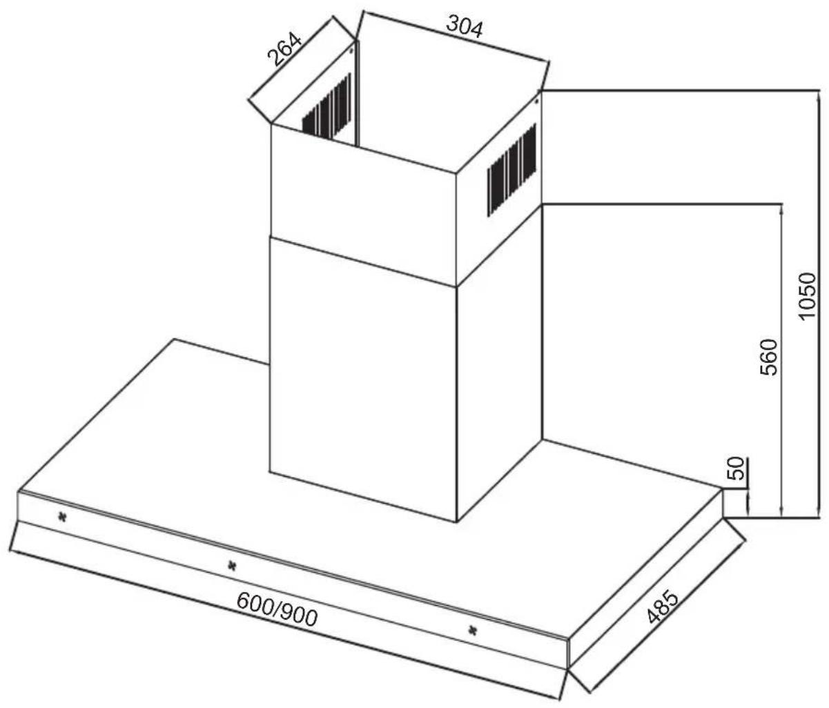
Model: TCR60BK and TCR90BK

The manufacturer will not be responsible for any damage to property or to persons caused by incorrect installation or improper use of the appliance.
The manufacturer is not responsible for any inaccuracies, due to printing or transcription errors, contained in this handout. In addition, the appearance of the figures reported is also purely indicative.
The manufacturer reserves the right to make changes to its products when considered necessary and useful, without affecting the essential safety and operating characteristics.
Technika constantly seeks ways to improve the specifications and designs of their products.
Whilst every effort is made to produce up to date literature, this document should not be regarded as an infallible guide.
Actual product only should be used to derive cut out sizes.
All Technika Appliances must be installed by a qualified person/s with adherence to the relevant electrical, plumbing and gas codes, with compliance being issued as required by state or national legislation.
Additionally all Technika Upright cookers must have chains installed correctly in adherence to the relevant gas and plumbing codes by a Licensed installer.
For maximum effectiveness and efficiency all rangehoods should be installed with the use of ductwork, by a licensed installer with adherence to the relevant state and national building codes and regulations.
All Technika appliances are for Domestic use only, and must be installed by a licensed installer into Domestic Applications only, without exception and to the required Authorities guidelines. Any installation outside of this will VOID warranty.
Alfresco areas are not a Domestic application.
TECHNIKA®
COOKING WITH PASSION
TECHNIKA PTY LTD ACN 069 686 326
77 FILLO DRIVE SOMERTON VIC 3062
General : 1800 649 969 - Service : 1800 333 244
Technika After Sales Service - P.O. Box 543 SOMERTON VIC 3061
- Instructions for Use and Installation
- For Your Safety
- Use and Care
- Installation
- Safety Precautions
- Before connecting to the electricity network:
- WARNINGS!
- LED Lamps
- Controls
- FUNCTION KEYS: (Fig.4)
- Cleaning your rangehood
- Troubleshooting
- Disposal
- Electrical Connection
- Instructions for Installation
- Fixing to the Wall
- Fixing the Decorative Telescopic Flue
- Dimensions
Brand : Technika
Model : TCR90BK
Category : Range hood