EVC130P - Video Conferencing System AVer - Free user manual and instructions
Find the device manual for free EVC130P AVer in PDF.


| Product Type | Video Conferencing System |
| Model | EVC130P |
| Camera Type | PTZ Camera with 16x Optical Zoom |
| Camera Sensor | 2MP Low Lux Sensor |
| Video Resolution | Up to Full HD (1920x1080 @ 30fps) |
| Dual Monitor Support | Yes, via HDMI and VGA |
| Content Sharing | VGA or IP, up to 720p @ 30fps |
| Network Interface | 10/100/1000 Gigabit Ethernet |
| Video Bandwidth | 64 Kbps to 4 Mbps |
| Protocols | H.323, SIP, IPv4, IPv6, Wake-on-LAN |
| Audio Codecs | G.711, G.722, G.722.1, G.722.1C, G.728 |
| Audio Features | G.722.1C Wideband, Microphone Array Included |
| Security | AES 128-bit Encryption |
| Remote Control | Infrared (IR) Remote with Full Camera Control |
| Camera Pan/Tilt/Zoom | Pan: ±100°, Tilt: ±25°, Zoom: 16x Optical |
| Power Supply | DC 12V via Included Power Adapter |
| Ports | HDMI In/Out, VGA In/Out, Audio In/Out, MIC In, LAN, USB x2 |
| Package Contents | Main System, Camera, Microphone, Remote, Power Adapter, Cables, Warranty Card |
| Warranty | 3-Year Limited Warranty |
| Supported Languages | Up to 22 Languages |
Frequently Asked Questions - EVC130P AVer
User questions about EVC130P AVer
0 question about this device. Answer the ones you know or ask your own.
Ask a new question about this device
Download the instructions for your Video Conferencing System in PDF format for free! Find your manual EVC130P - AVer and take your electronic device back in hand. On this page are published all the documents necessary for the use of your device. EVC130P by AVer.
USER MANUAL EVC130P AVer
natural_image
Black video camera with lens and triangular head device on a flat base (no visible text or symbols)EVC150
natural_image
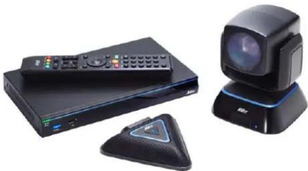
Product photo of a black remote control unit, a black radar monitor, and a black handheld device (no visible text or symbols)EVC130P
natural_image
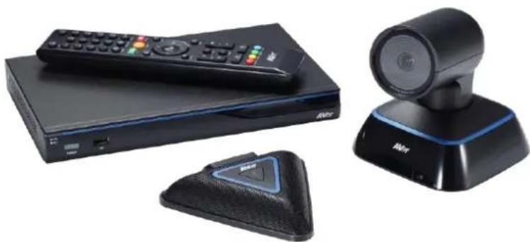
Product photo of AMr remote control devices including a remote, network switch, and sound recording device (no visible text or symbols)EVC100/EVC130
User's Manual
CONTENTS
INTRODUCTION .... 1
Features....1
Package Contents 2
INSTALLATION .... 3
Getting Familiar With the AVer EVC -Series....3
Main System....3
MIC 4
Camera....5
Remote Controller....6
Connections 8
Connecting Monitors (VGA Out/HDMI OUt) 9
Connecting the Camera (Camera In) 9
Connecting the MIC (MIC In) 10
Connecting the LAN (RJ-45) 10
Connecting the Power (DC 12V)....11
Connecting PC (VGA in) 11
Connecting the Audio (Audio IN/OUT) 12
USB Storage (USB Ports) 13
BEFORE INSTALLATION....14
Using the Camera 14
Infrared Sensor (IR)....14
Positioning the MIC 15
AVER EVC WIZARD SETUP 16
Start....16
Language....17
Site Name 17
Network Setting 17
Public IP Configuration (Outside of Firewall): 18
Private IP CONFIGURATION (Behind Firewall Port Forwarding): 19
SIP Setting....20
AVER EVC OPERATION....24
Before You Begin 24
Home Screen 24
Configuration Icons 24
Camera and MIC Icons 25
WAN Address 25
Real-Time Clock 25
System Info....26
Dial 26
Phonebook....29
Group....29
New Site (CONTACT in PHONEBOOK) 34
Contacts List....37
Favorite....37
Online Phonebook 38
Call History 39
General Setting 41
Call Settings....41
System Settings....44
Administrator 46
Monitor....49
Date and Time 51
Reset System 53
Default Layout....55
Video/Audio 56
Camera....56
Microphone 60
Video/Audio Codecs 62
Network 63
LAN Configuration....63
LAN Configuration (IPv6) 66
Advance Network....68
Firewall 69
SIP 71
SIP Server 75
Gatekeeper 78
Test Utilities 81
WEB CONFIGURATIONS 82
Using the WebTool 82
Managing Phonebook....84
Edit and Save 84
Download Phonebook Entries 85
Upload Phonebook Entries 85
Download Call History Entries 85
LDAP Setting 86
Online Phonebook 86
General Setting 87
Dual Stream Bandwidth Adjustment....87
Update System 87
EZ Join 88
Video/Audio 89
Primary Input source 89
Customized Logo and Boot Animation....90
SCENARIOS FOR LAN CONNECTION....91
Public IP Configuration (Outside of Firewall) 91
Private IP Configuration (Behind Firewall with Port Forwarding) 93
H.460 Gatekeeper with Firewall Traversal 95
TROUBLESHOOTING 96
Audio 96
Video/Display 96
Network 97
Others 100
REMOTE CONTROL BATTERY SAFETY INFORMATION......100
LIMITED WARRANTY 101
Limitations of Warranty 101
Disclaimer of Warranty 101
Limitation of Liability 102
Governing Law and Your Rights....102
FEDERAL COMMUNICATIONS COMMISSION STATEMENT (CLASS A)....102
Class A ITE 102
CE Class A (EMC)....103
COPYRIGHT 103
Trademarks 103
Disclaimer 103
Introduction
Thank you for choosing EVC-Series which offers professional videoconferencing experience in new cost performance benchmark.
EVC-Series gives you the latest technologies; slim form factor, flexible integration options and backward compatibility to most videoconferencing install bases. It makes any business meetings and special events much more reliable, effective, and secure.
Features
▶ Make point-to-point call to another H.323 or SIP videoconferencing system
▶ Support full content sharing experience (send and receive) at 30fps, send content from VGA or IP
▶ Dual monitor support via HDMI and VGA
▶ Support CIF (352x240) up to Full HD (1920x1080 30fps) video call (EVC100 only up to 720p)
EVC100/EVC130 with Fixed camera is 88 wide degree 4x Digital zoom with 2Mp low lux sensor
▶ EVC130P with PTZ camera is 16x Optics PTZ camera with 2Mp low lux sensor
EVC150 with PTZ camera II is 18x Total zoom PTZ camera with 2Mp low lux sensor
▶ Include one microphone array, much better audio pick up than competitor offering
▶ 10/100 and Gigabit Ethernet; video bandwidth from 64Kbps to 4Mbps
▶ Support IPv4 / IPv6 and Wake-on-LAN (WOL)
▶ User-friendly on screen operation, support up to 22 languages
▶ Support Phonebook download, upload and edit
▶ Call history lookups of received, placed and missed calls, allow directly saving it to favorite call list
▶ Support H.460 Gatekeeper for NAT and firewall traversal
▶ G.722.1C* wideband support
▶ Infrared (IR) remote control has power button; system supports remote API for AV integration
▶ Secure communication using AES 128bit encryption
Package Contents
The following items are included in the package. Please check if each item is available before using.
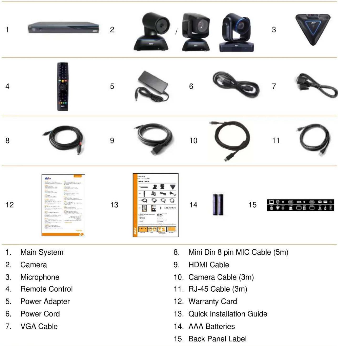
- Main System
- Camera
- Microphone
- Remote Control
- Power Adapter
- Power Cord
-
VGA Cable
-
Mini Din 8 pin MIC Cable (5m)
- HDMI Cable
- Camera Cable (3m)
- RJ-45 Cable (3m)
- Warranty Card
- Quick Installation Guide
- AAA Batteries
- Back Panel Label
The power cord will vary depending on the standard power outlet of the country where it is sold. The camera will vary depending on choosing EVC model of EVC100/EVC130/EVC130P/EVC150.
Getting Familiar With the AVer EVC -Series
EVC includes Main System, MIC, Camera and Remote Controller.
MAIN SYSTEM
Front Panel:

| Name | Function |
| (1) LED Indicator | Show you the status of your LAN connection.■ Solid Green: LAN connection is successfully■ Flash Green: Data transmission is processing through the LAN connection. |
| (2) POWER Button | Press this button to turn on/off main system. Red: power off; Blue: power on |
| (3) USB Port | Use to connect the USB storage for system log saving and FW upgrade. |
Back Panel:

| Name | Function |
| (1) POWER Port | Connect the power supply cord and adapter to the power port located on the back panel. And connect the other end of the power cord to a suitable power outlet. |
| (2) USB Port | This port is the same as USB Port located on the front panel. |
| (3) CAMERA IN Port | Connect the camera to the main system via a camera cable. |
| (4) VGA OUT Port | Connect the VGA cable to the VGA OUT port located on the back panel, and connect the other end of VGA cable to a display device to output video signal. In dual screen configuration, the output screen connected to this port will be set up to secondary screen automatically. |
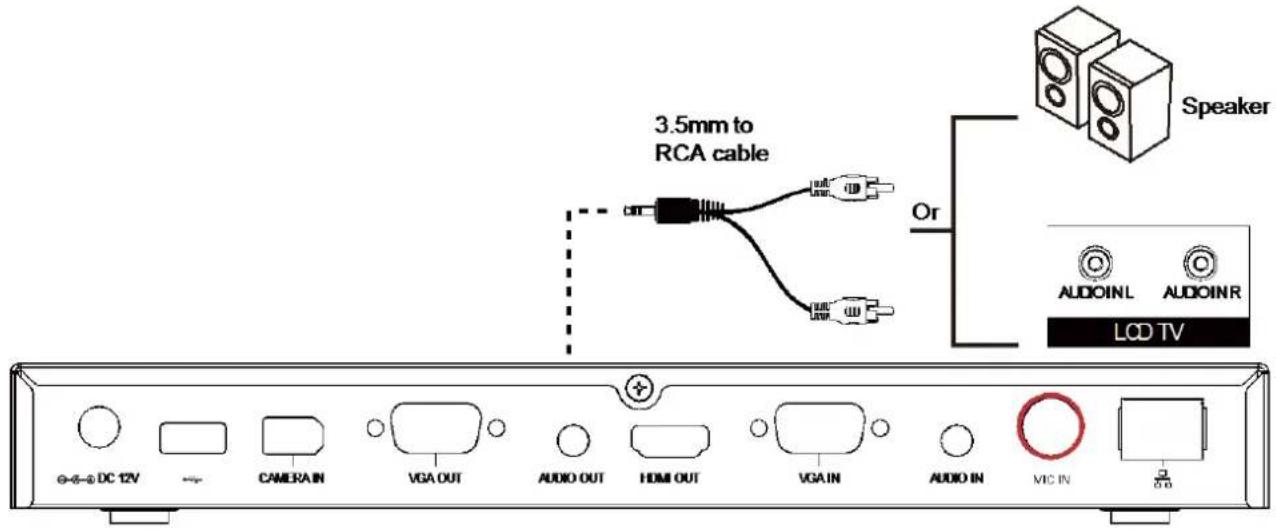
| (5) AUDIO OUT Port | Use to connect the main system to external speakers or amplifiers for audio signal output. |
| (6) HDMI OUT Port | Connect an HDMI cable from the HDMI monitor to HDMI OUT port located on the back panel. The HDMI interface allows you to transmit both audio and video signals over a single cable (HDMI cable). In dual screen configuration, the output screen connected to this port will be set up to primary screen automatically. |
| (7) VGA IN Port | Connect the VGA cable to the VGA IN port located on the back panel, and connect the other end of VGA cable to a VGA input sources (ex. Document camera, Laptop or Desktop) to input video signal. |
| (8) AUDIO IN Port | Receive audio signal from an external audio source through RCA left and right audio connections. |
| (9) MIC IN Port | Receive audio signal from MIC device via a mini din 8 pin MIC cable. |
| (10) LAN Port | Use the RJ-45 Ethernet cable to connect an IP-based network to the LAN port. |
MIC
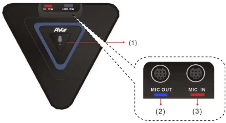
| Name | Function |
| (1) Mute | Mute/Unmute the Mic. Blue: Unmute; Red: Mute |
| (2) MIC OUT Port | Outputs audio signal from the MIC to main system. |
| (3) MIC IN Port | Receive audio signal from the second MIC and pass it through the MIC OUT to the main system. |
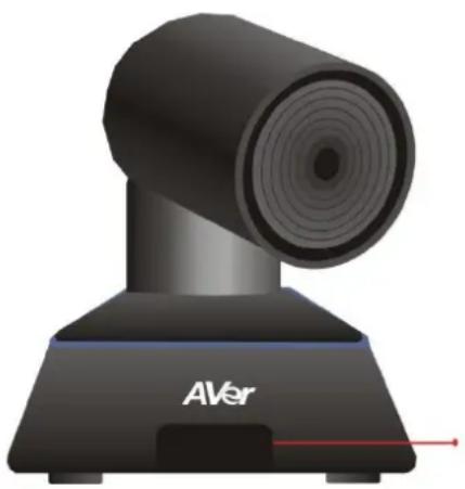
natural_image
3D rendering of a black AVer video camera with no visible text or symbols on the device body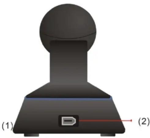
natural_image
3D rendered mechanical component with labeled parts (1) and (2), no readable text or symbols beyond labels| Name | Function |
| (1) IR Sensor | Receive IR signal from the remote control for system operation. Amber light blinks when it detects key pressing event from remote. |
| (2) CAMERA OUT Port | Connect the camera cable to the CAMERA OUT port located on the back of camera and CAMERA IN port located on the back panel of mair system for a video transmission. |
REMOTE CONTROLLER
The remote controller requires two “AAA” batteries (included). Make sure the batteries are installed properly before using the remote controller. Aim the remote controller at the infrared sensor of your Aver EVC camera to remote control the unit.
The remote controller included is only available for EVC-Series.
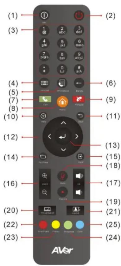
| Name | Function |
| (1) Info | Press this button to display the call statistics information. |
| (2) Power | Press this button to power on/off the main system. |
| (3) Numeric Pad | Use to enter alphanumeric. Press  on and hold can switch between numeric mode and alphanumeric mode. on and hold can switch between numeric mode and alphanumeric mode. |
| (4) Keypad | In enter mode, press this button to display the on-screen keyboard. |
| (5) Phone Book | a. Search contacts to make a call.b. Add, edit, delete or create group contact entries. |
| (6) Delete | Press this button to back delete one character at a time. |
| (7) Call | Start a call. |
| (8) Home | Bring up the main screen. |
| (9) Hang up | End the call. |
| (10) Help | In Home menu and video screen mode, press it to display on-screen help information. |
| (11) Back | Return to previous OSD menu. |
| (12) Navigation Buttons(▲,▼) ▲ ▶ | a. Use these buttons to navigate through the selections in OSD menus or on-screen keyboard.b. Pan and tilt the camera to adjust the viewing.c. Pan, tilt the zoomed in camera image or captured image. |
| (13) Enter | a. Make a selection in OSD menus.b. Accept incoming calls.c. Display the site name and icon during the meeting.d. Auto Focus function(PTZ camera only) |
| (14) Far/Near | Select to control either near site or far site camera. The cam ctrl icon will appear on the screen to indicate which site's camera you are |
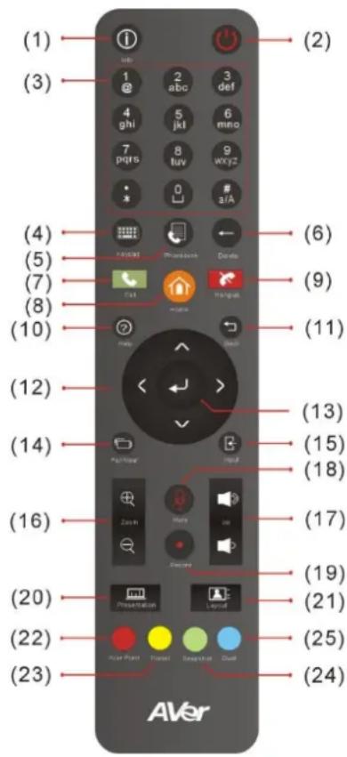
| controlling. The cam ctrl icon will disappear after press the Far/Near key 5 sec. | |
| (15) Input | Switch the OSD menu display on VGA or HDMI monitor (dual monitor). |
| Name | Function |
| (16) Zoom +/- | Increase/decrease the camera zoom or the captured image magnifications. |
| (17) Vol +/- | Increase/decrease the speaker volume. |
| (18) Mute | Muto/Unmute the MIC. The mute icon will appear when the MIC is muted. The mute icon will become translucent after enabling 5 sec. |
| (19) Record Only support for EVC130. | Start/Stop video recording. The video recording can only be saved to a USB flash drive. You do not need to be on a video conference to record. |
| (20) Presentation | Share the content that comes from either the VGA IN port source or the latest captured image. The present icon will appear on the screen when the presentation function is enabled. The icon will disappear after 5 sec. |
| (21) Layout | Change the screen layout. |
| (22) Aver Point | Aver Point To be developed. |
| (23) Preset | a. Press and hold for 3 sec. to set the position of the camera to a preset from 0~9.b. Press to move the camera to a selected preset point number. |
| (24) Snapshot | Capture the image from the camera (OSD menu is not included) and save to external USB pen drive. |
| (25) Dual | Switch to dual screen mode. This splits the video conferencing screen and present screen onto two separate monitors (two monitors must be connected to use the feature, one through HDMI and one through VGA).Press and hold can switch to OSD menu between primary and secondary screen. |
Connections
Before making the connections, make sure all devices are powered off. Refer to the illustrated connections below and also to the user manual of the device you are connecting to the AVer EVC-Series system.
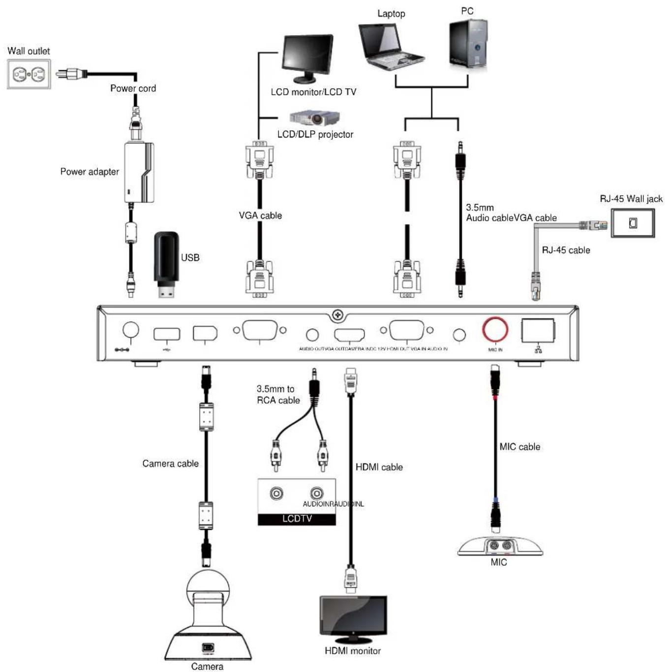
Make sure all connections have been connected successfully before powering on the system.
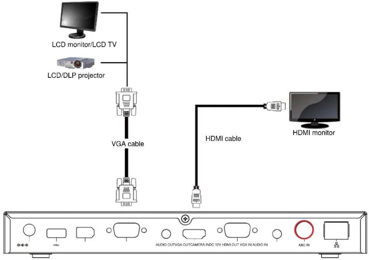
CONNECTING MONITORS (VGA OUT/HDMI OUT)
Locate the VGA/HDMI input port of the graphics display device and connect it to VGA OUT/HDMI OUT port of the AVer EVC with the supplied VGA/HDMI cable. You can configure the VGA OUT and HDMI OUT ports at the same time upon a dual screen configuration.
flowchart
graph TD
    A["LCD monitor/LCD TV"] --> B["VGA cable"]
    C["LCD/DLP projector"] --> B
    B --> D["HDMI cable"]
    D --> E["HDMI monitor"]
    B --> F["+"]
    D --> G["AUDIO OUTVGA OUTCAMERA INDC 12V HDMI OUT VGA IN AUDIO IN MIC IN"]
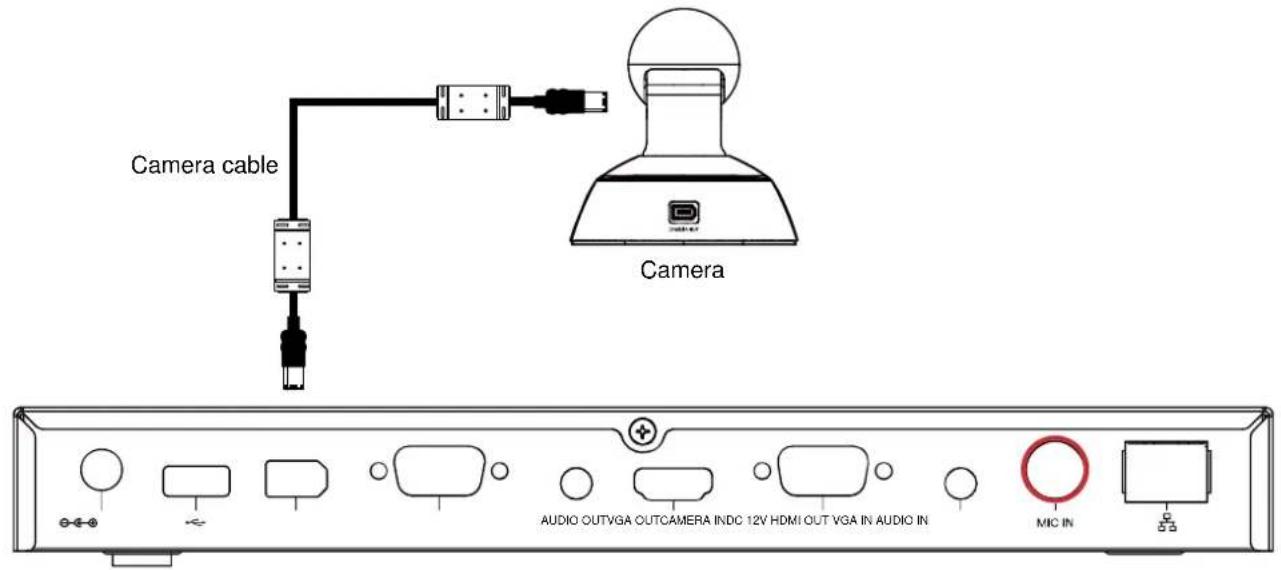
CONNECTING THE CAMERA (CAMERA IN)
Locate the port on the back of the camera and connect it to the CAMERA IN port of the EVC with the supplied camera cable.
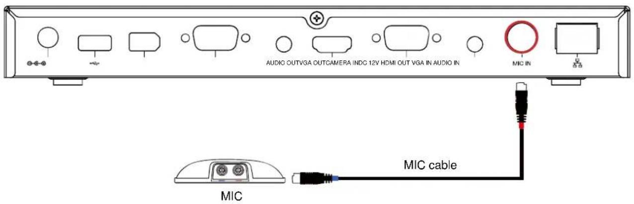
CONNECTING THE MIC (MIC IN)
Use the supplied MIC cable and connect the red tag connector to the MIC IN port of the EVC. Then connect the other end of the MIC cable with the blue tag to MIC OUT port.
Press the button on the top of AVer EVC-MIC to mute/un-mute the MIC.
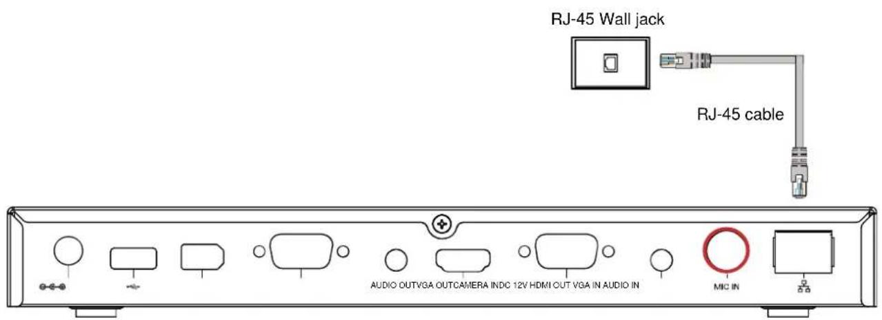
CONNECTING THE LAN (RJ-45)
Connect the LAN port of AVer EVC to a RJ-45 wall jack or Ethernet hub with the supplied RJ-45 cable.
It is requires an IP-based network before beginning LAN connection.
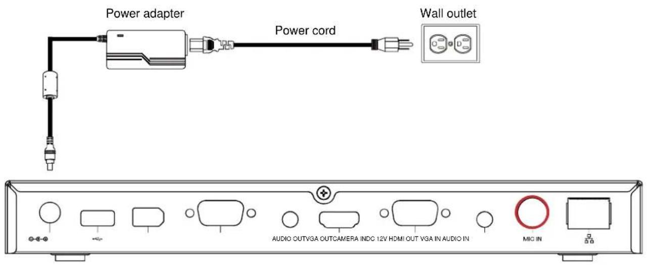
CONNECTING THE POWER (DC 12V)
Connect the power adapter to a standard 100V\~240V AC power outlet with the supplied power adapter and power cord.
(1) To prevent shock, make sure all the connections on the main system are connected successfully before connecting the power cable and turning on the power.
(2) Make sure to use the supplied available power adapter.
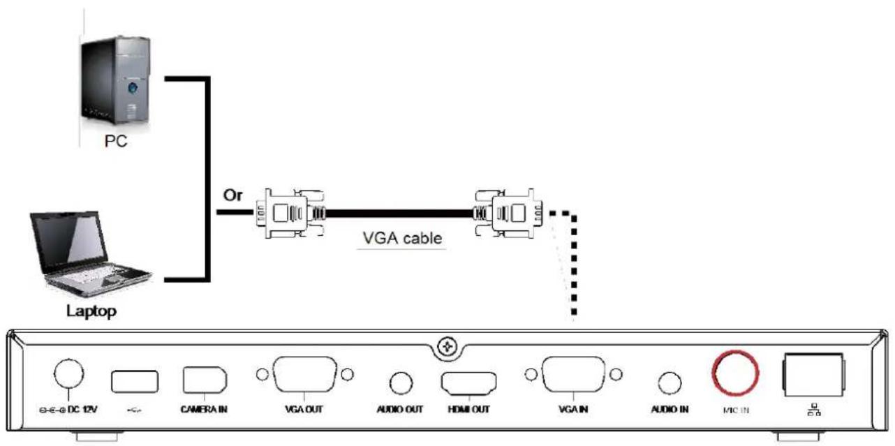
CONNECTING PC (VGA IN)
Locate the VGA output port of the Laptop or Desktop and connect it to VGA IN port of EVC with the supplied VGA cable for an image display.
To share the video signal from the computer, press PRESENT and select "VGA".
flowchart
graph TD
    PC["PC"] -->|Or| VGA_cable["VGA cable"]
    Laptop["Laptop"] -->|Or| VGA_cable
    VGA_cable -->|Output| Media["Media In"]
    Media -->|Control knob| PC
    Media -->|Control knob| Laptop
CONNECTING THE AUDIO (AUDIO IN/OUT)
AUDIO IN:
Locate the AUDIO output port of the Laptop or Desktop and connect it to AUDIO IN port of AVer EVC with the supplied 3.5mm Audio cable.
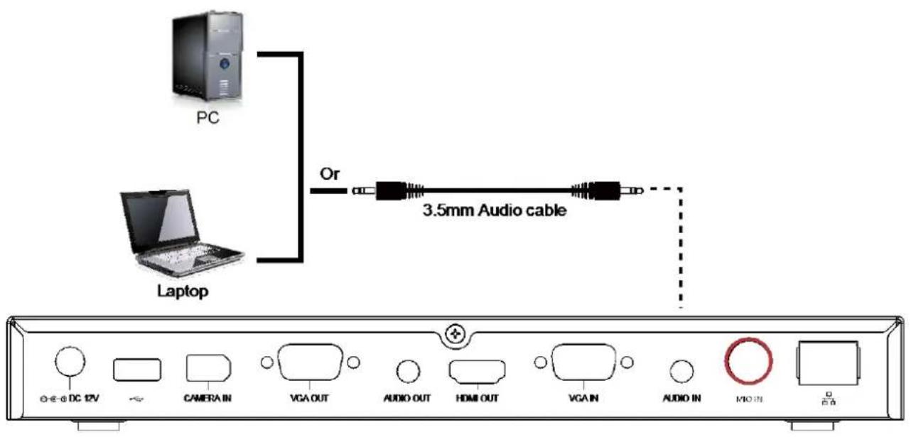
AUDIO OUT:
Locate the AUDIO in port of the LCD TV speaker or normal speaker and connect them to AUDIO OUT port of AVer EVC with a RCA cable.
USB STORAGE (USB PORTS)
EVC main system supports two USB2.0 interface for saving data. One is located on the front panel of main system; another is located on the back panel.
[Note] The USB ports only support USB pen drive for F/W upgrading and saving log file; they NOT supply 5V power for any external devices.
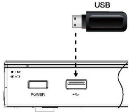
Front
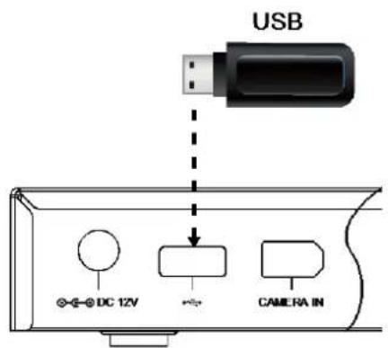
Back
Before Installation
This chapter explains the best way to position EVC-Series in a conference room.
Using the Camera
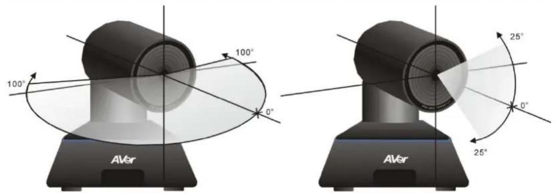
EVC100/130 with a detached camera that can pan ( +-100 deg range), tilt ( +-25 deg range) and zoom (4X digital) by using the ▲, ▼, ▶, ▶ and zoom +/- buttons on remote controller.
EVC130P with a detached camera that can pan ( +-100 deg. range), tilt ( +-25 deg. range) and zoom (16x Optics) by using the ▲, ▼ and zoom +/- buttons on remote controller.
EV150 with a detached camera that can pan ( ∅+-130 deg. range), tilt ( ∅+90/-25 deg. range) and zoom (18x total zoom with 12x Optical, 1.5x Digital zoom) by using the , ▲ ▼ d ▶ or ▶ +/- buttons on remote controller.
Avoid physically turn camera while system is powered on to prevent permanent damaging the motors and gears and void the warranty. Always use the remote control to pan and tilt the camera head.
Infrared Sensor (IR)
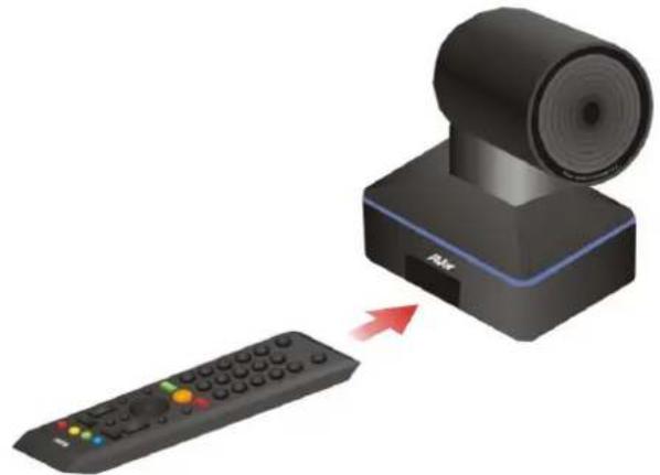
Aim the remote controller at the camera infrared sensor to operate the unit.
natural_image
Illustration of a black video camera with a red arrow pointing to it, connected to a remote control (no text or symbols present)Positioning the MIC
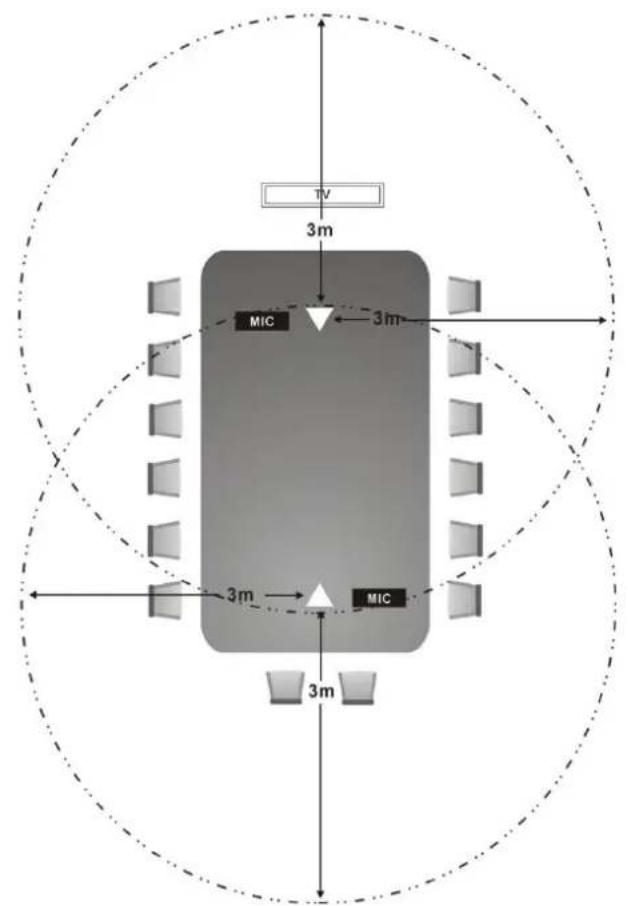
The best distance for EVC-MIC to receive audio signal is within 3m.
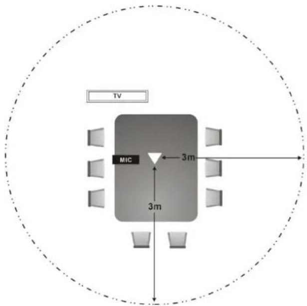
Single Microphone
For the first time using AVer EVC system, the Installation Wizard will guide the user to setup EVC system step by step. After completing the wizard setup, user may start to use the EVC system.
In Installation Wizard, user can use the following buttons on remote controller to move between the selections and make/confirm selection.
: To expand the drop-down list, make/confirm the selection.
√/√Move the cursor up or down.
Move the cursor to right or on Next button.
<: Move the cursor to left or on Back button.
START
Please follow the below description to complete the wizard setup.
Connect your EVC system well and turn on the power. After your EVC system starting, user will see the Installation Wizard screen shown up.
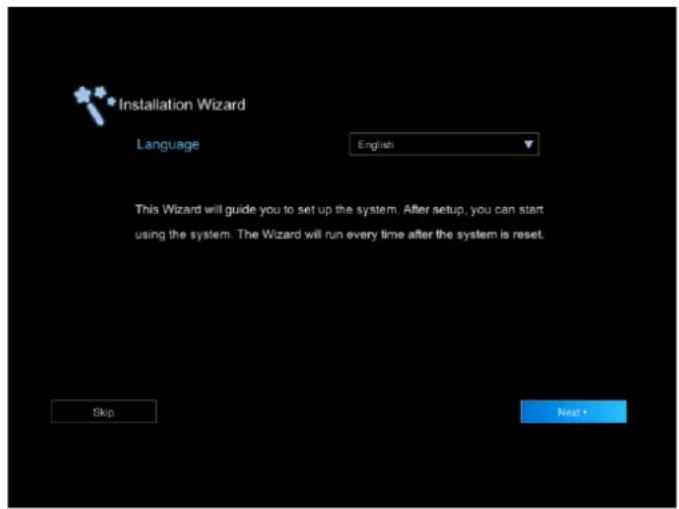
If you want to skip the Wizard setup, press < button move to Skip button and press 🤒 go to Home page.
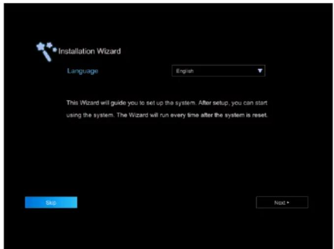
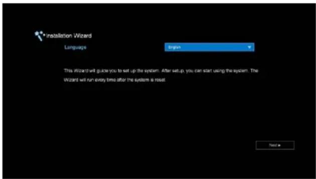
LANGUAGE
Select the language of the EVC system.
Press expand the drop-down list. Then, use ▶ on to move the selection and press make the selection. After selecting, press ▶ move to Next option and press to go next step.
SITE NAME
Assign a name for EVC system. Use the numeric pad on remote controller to enter the site name.
After entering the site name, press ➤ to move to Next button and press 🔥 go next step.
To go back to last step, press ▶to move to Back option and press 📋confirm.
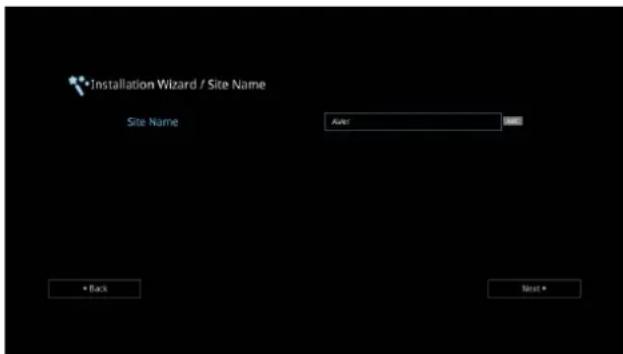
[Note]
(1) Repeat press the number button to select the character that user wants to enter.
(2) The site name is character only
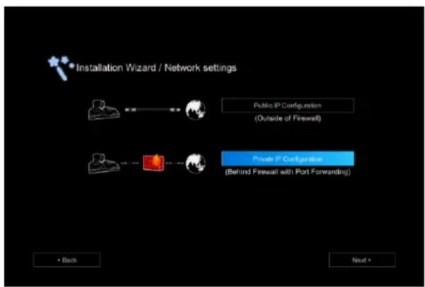
NETWORK SETTING
Select the network environment that user has used.
Use ▲r □on to move to the selection and press ▼ confirm the selection.
[Note] User can refer to chapter of Scenarios For LAN Connection for the description of network environment.
After selecting the network setting option, user need to configure the network parameters. Follow the below description to setup the network settings.
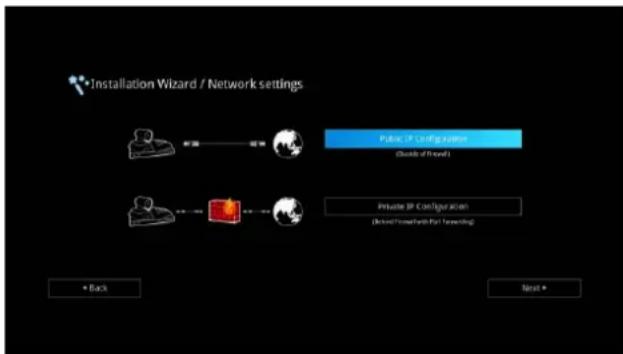
flowchart
graph LR
    A["Installation Wizard / Network settings"] --> B["Public IP Configuration\n(Quick of Power)"]
    A --> C["Private IP Configuration\n(Quick/Forward/Part Networking)"]
    D["Back"] --> E["Next"]
Your EVC system is connecting directly to the internet. Select the IP mode.
Obtain IP address by DHCP: Configure the system to automatically obtain an IP address from the DHCP server. The EVC system will automatically get a IP address which assigned by your DHCP server on LAN. The IP address and related information will display. Click OK to accept the setting.
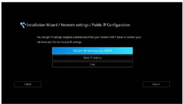
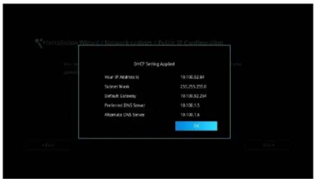
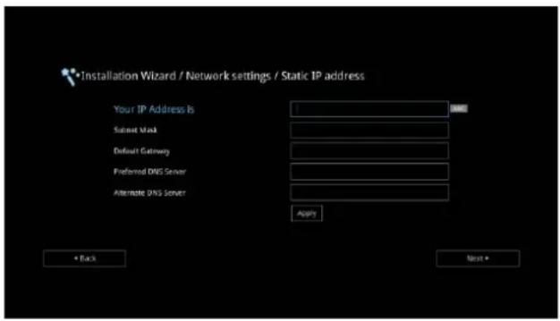
Static IP: Configure the system to use the assigned IP address. Select this when the public IP address is available.
Enter the following information and click Apply to save the settings. To go to next step, click Next and click Back to go back to Network Setting page.
- Your IP Address is: Enter your IP address manually.
- Subnet Mask: Enter the subnet mask address when the system does not automatically obtain the subnet mask
- Default Gateway: A gateway is a network point that acts as an entrance to another network. Enter the gateway address when the system does not automatically obtain the gateway.
- Preferred DNS Server: Domain Name System (DNS) servers convert human friendly names (for example: www.example.com) to IP addresses (218.77.272.166) that let machines be found on the network. The preferred DNS server is the one your computer asks first. The alternate is a backup. Enter the Preferred and Alternated DNS Server address.
- Alternate DNS Server: Enter another Domain Name server for second choice.
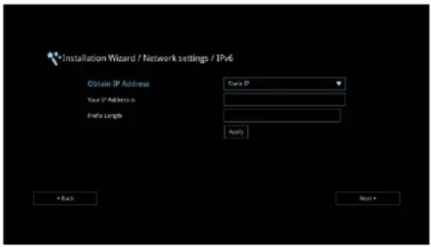
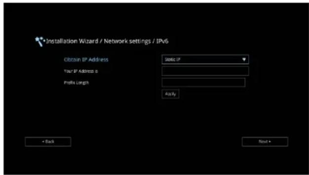
IPv6: IPv6 is an evolutionary upgrade to the Internet Protocol. IPv6 will coexist with the older IPv4 for some time. IPv6 addresses are 128-bit IP address written in hexadecimal and separated by colons.
Select and enter the following information and click Apply to save the settings. To go to next step, click Next option and click Back to go back to Network Setting step.
1. Obtain Address is
(1) Static IP: Configure the system to use the assigned IP address. Select this when the public IP address is available.
(2) Auto: Obtain the dynamic IP address automatically. User needs to enter the IP address and prefix length in following.
- Your IP Address is: Enter your IP address manually.
- Prefix Length: Prefix Length allows you to place as many IPv6 devices as the underlying network medium allows.
PRIVATE IP CONFIGURATION (BEHIND FIREWALL PORT FORWARDING):
Your EVC system is connecting to the internet through a firewall.
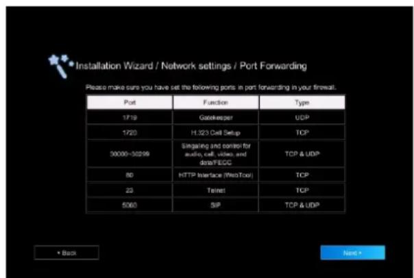
Please make sure you have set the following ports in port forwarding in your firewall. Then, click Next to select the IP mode of your network
Obtain IP address by DHCP: Configure the system to automatically obtain an IP address from the DHCP server. The EVC system will automatically get a IP address which assigned by your DHCP server on LAN. The IP address and related information will display. Click OK to accept the setting.
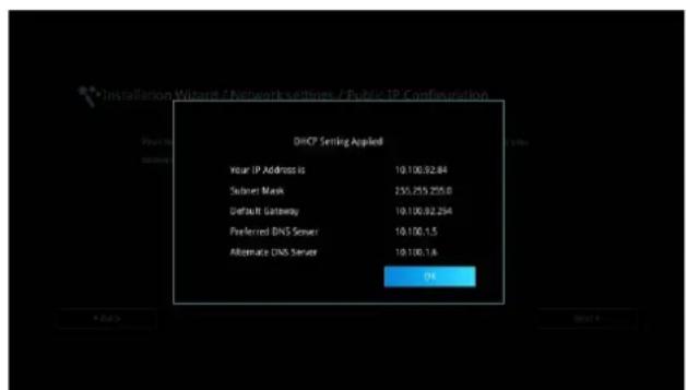
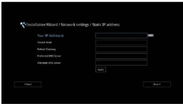
Static IP: Configure the system to use the assigned IP address. Select this when the public IP address is available.
Enter the following information and click Apply to save the settings. To go to next step, click Next and click Back to go back to Network Setting page.
- Your IP Address is: Enter your IP address manually.
- Subnet Mask: Enter the subnet mask address when the system does not automatically obtain the subnet mask
-
Default Gateway: A gateway is a network point that acts as an entrance to another network. Enter the gateway address when the system does not automatically obtain the gateway.
-
Preferred DNS Server: Domain Name System (DNS) servers convert human friendly names (for example: www.example.com) to IP addresses (218.77.272.166) that let machines be found on the network. The preferred DNS server is the one your computer asks first. The alternate is a backup. Enter the Preferred and Alternated DNS Server address.
-
Alternate DNS Server: Enter another Domain Name server for second choice.
IPv6: IPv6 is an evolutionary upgrade to the Internet Protocol. IPv6 will coexist with the older IPv4 for some time. IPv6 addresses are 128-bit IP address written in hexadecimal and separated by colons.
Select and enter the following information and click Apply to save the settings. To go to next step, click Next option and click Back to go back to Network Setting step.
1. Obtain Address is
(1) Static IP: Configure the system to use the assigned IP address. Select this when the public IP address is available.
(2) Auto: Obtain the dynamic IP address automatically. User needs to enter the IP address and prefix length in following.
-
Your IP Address is: Enter your IP address manually.
-
Prefix Length: Prefix Length allows you to place as many IPv6 devices as the underlying network medium allows.
SIP SETTING
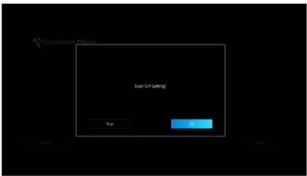
Session Initiation Protocol (SIP) allows you around the world to communicate using your supported devices over the Internet. After setting network, user can choose to setup SIP or Skip SIP setting.
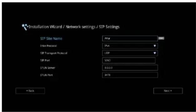
To setup SIP, enter or select the following information
- SIP Site Name: Enter the SIP site name for others to identify. The SIP site name may be the same or different then the domain for Web activity. Use numeric pad to enter the SIP site name in column.
- Internet Protocol: Select to use IPv4 or IPv6
as IP protocol. Press

expand
drop-down list and use

t move the
selection. Press

confirm the selection.
- SIP Transport Protocol: Select the SIP Transport Protocol type from the drop-down list for using. There are two types of Internet Protocol (IP) traffic. They are Transmission Control Protocol (TCP) and User Datagram Protocol (UDP). To ensure proper connection, verify if both calling parties are using the same transport protocol. By default, it is set to UDP.
(1) TCP: TCP is connection oriented. Once a connection is established, data can be sent bidirectional.
(2) UDP: UDP is a simpler, connectionless Internet protocol. Multiple messages are sent as packets in chunks using UDP.
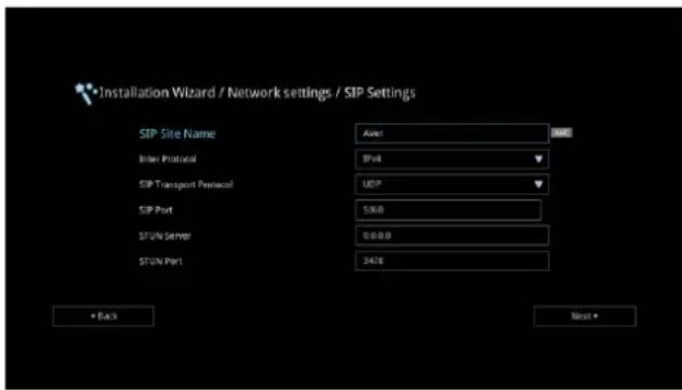
- SIP Port: Change this value only if you use specific settings in your network system. By default, the SIP port is set to 5060.
- STUN Server: STUN (Session Traversal Utilities for NAT) is a standardized set of methods and a network protocol to allow an end host to discover its public IP address if it is located behind NAT.
- STUN Port: Enter the port number of STUN server.
A typical SIP session involves a client requesting a session with a SIP server. After the request is received, the SIP server returns a response to the user indicating the availability of the session. After setting SIP, user can choose to setup SIP Server Registration or Skip.
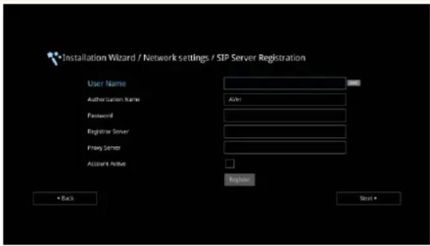
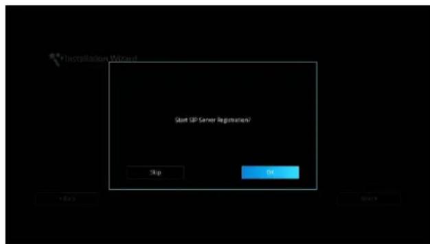
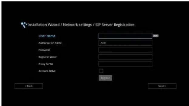
To setup SIP Server Registration, enter the following information and click Register to save the settings. After completing, click Next to go next step.
- Terminal Name: Enter the terminal server name.
- Terminal Password: Enter the password of terminal server.
- Registrar Server: Registrar Server accepts registrations from users and places these registrations, (which is essentially location information), in a database known as a location service. Enter the Registrar Server name that you want to use.
- Proxy Server: Proxy Server is computing device (typically a server) that interfaces between data processing devices and others within a communications network. These devices may be located on the same local area network or an external network. Enter the used Proxy Server name.
DATE AND TIME SETTING
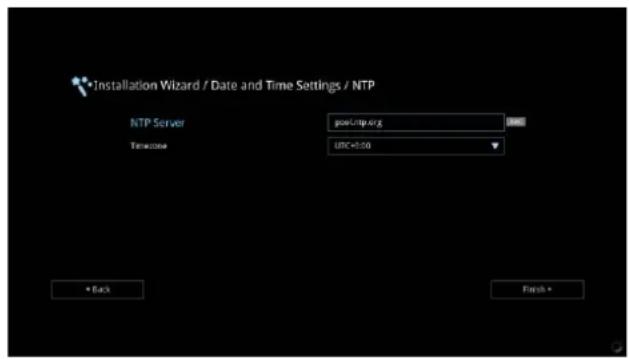
Setup the EVC system date and time. User can choose to use NTP server to adjust the date/time or manually enter the current date/time.
NETWORK TIME PROTOCOL (NTP)
Network Time Protocol (NTP) is a protocol that is used to synchronize system clock times in network of device.
- NTP Server: The Network Time Protocol (NTP) allows administrators to synchronize all network computers to a main server. This keeps all network machine clocks on the same time. Enter the NTP Server name that you want to follow.
- Time Zone: Timezone allows you to adjust the time when you are in a different country or area so that you can keep the same time with your original area. Most of the time zones on land are offset from Coordinated Universal Time (UTC) by a whole number of hours (UTC-12 to UTC+14)
MANUALLY SETTING
Enter the present year, month, date, hour, minute, and second by yourself
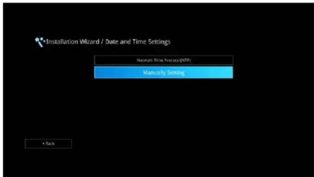
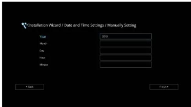
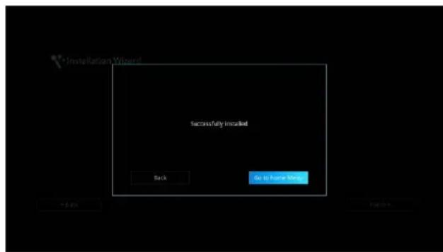
After completing date/time setup, click Finish to complete the Installation Wizard setup. Before that, user can back to previous page or go to home menu. How to dial a call; refer to chapter of Making a Call.
Aver EVC OPERATION
Connecting the camera, microphone, main system, display and power, press the power button to turn on EVC. Power button starts blinking blue light, Aver logo shows up followed by an animation and music. In 30 seconds camera image and home screen appear on screen. Aim the remote controller to camera and start configuring AVer EVC.
Before You Begin
Basic Operation
Navigation buttons: Use the ∧, √, ◀ and > buttons to move the selection on the remote controller.
Enter button: Use the ⬆ confirm the selection on the remote controller.
Apply: Make the changed value to take effect. (For AVer EVC Application)
Save: Accept the created value and save it to the system.
Cancel: Cancel the changed value and exit the present screen.
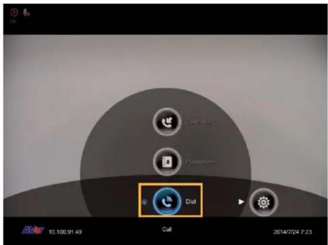
Home Screen
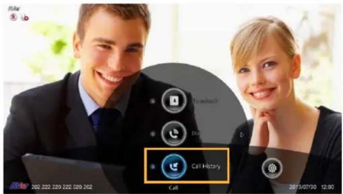
There are 4 selections on the Home screen: Dial, Phonebook, Call History, and Setting. Simply use the navigation buttons to move between selections and press 📄 confirm the selection. You can easily place a call and select the site contact either in Dial, Phonebook or Call History. The administrator can set a security password to prevent changes made to the system setting and WebTool access.
CONFIGURATION ICONS
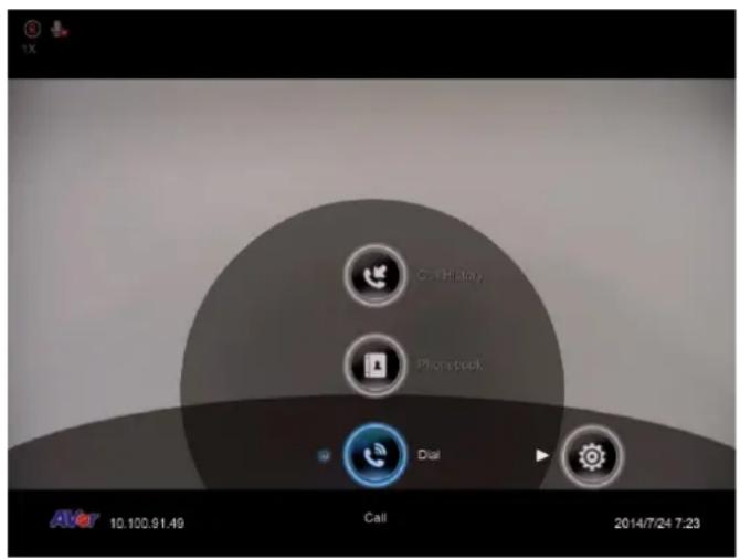
Dial, Phonebook and Call History
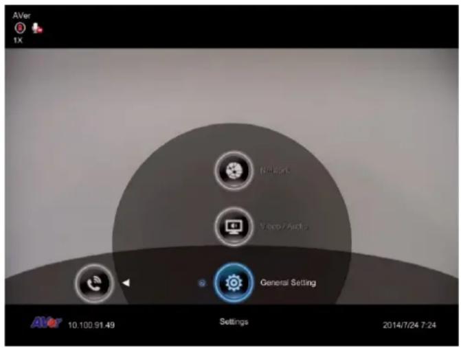
Settings include General Setting, Video/Audio and Network.
CAMERA AND MIC ICONS
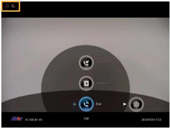
On the upper left-hand corner of your home screen, you may see camera and MIC indications.
If the Camera connection is ok, 📄 in the upper left corner of your home screen. Otherwise, “Camera Disconnected” warning message is displayed and screen is blue.
If the MIC connection is ok, 📁 is on the upper left corner of your home screen. Otherwise, 📁 is displayed indicating microphone is mute. Try pressing the mute button on microphone or remote controller to unmute it (LED indicator on microphone turns blue).
WAN ADDRESS
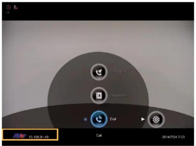
On the lower left corner of your home screen you can find current WAN IP address.
REAL-TIME CLOCK
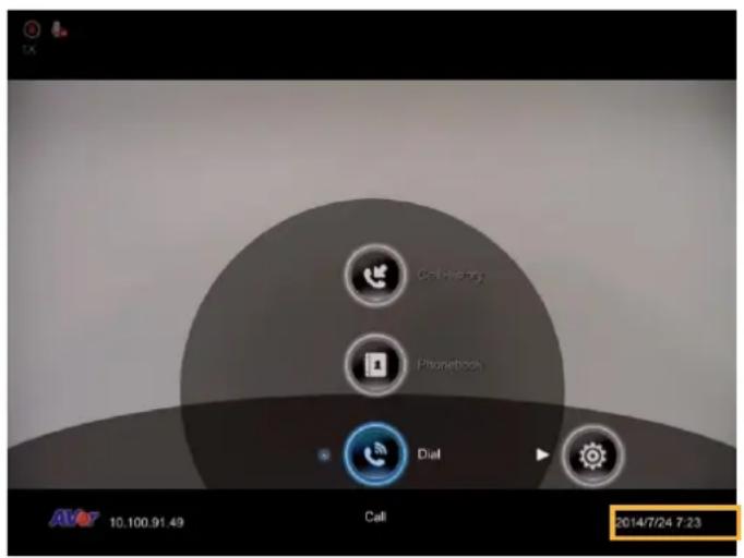
On the lower right corner of your home screen, you can find the current Date and Time once system sets up properly.
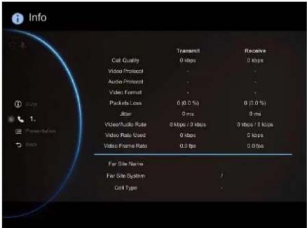
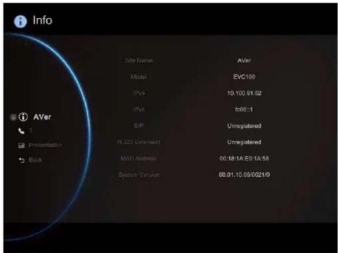
SYSTEM INFO
Press (6) button to switch to system information page.
The System Info shows you the relative information about your EVC main system including Site Name, Model name, Maximum Allowable Sites, IP Address, MAC Address and System Version.
Also, you can view call status while call is connected.
- Make a call.
- When call is connected, press ⓘ (Info) button.
- Select the call and you should see the current call status.
Dial
Dial selection allows you to enter dial screen and make a call.. Press button on the remote controller has the same effect.
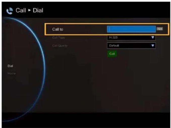
Call to
Use the number keys on the remote controller to enter the IP address or number or SIP URI (sip:username:password@host:port) you want to call. AVer remote controller supports alpha-numeric operation, press numeric key multiple times to select the alphabet or symbol.
[Note] Press k# on and hold can switch
between numeric mode(123) and alphanumeric mode(ABC/123).
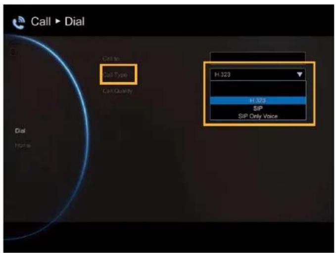
Call Type
AVer EVC supports H.323, SIP, and SIP Only Voice calls. H.323 is commonly used to communication to other videoconferencing room systems. SIP is commonly used to communicate with other VoIP devices. SIP Only Voice is used when other conference site could not recognize EVC video code, only transfer voice Use the button to select which type of call type you want to make then press confirm.
[Note] H.322 and SIP call type can be existed in a same conference call meeting.
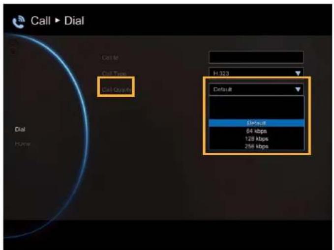
Call Quality
For the Call Quality selection, enter the desired call quality (or network bandwidth) from the drop-down list (default or 64K up to 4M bit per second).
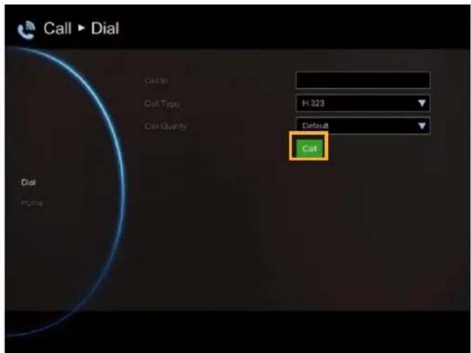
Select the "Call" on the Dial configuration screen then press make a call.
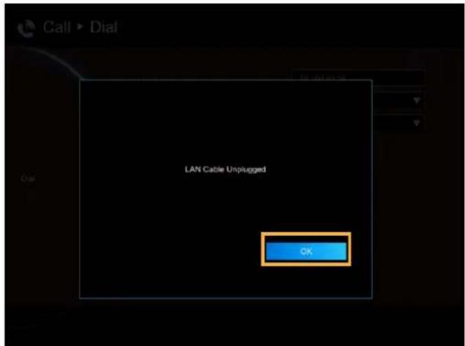
Make sure the network jack is plugged in and network is working properly before making a call; otherwise, the "Network Jack Unplugged" information will appear. Click "OK" to reconfirm the network connection.
Phonebook
Phonebook allows you to create and edit contact information, group contacts by category, search contacts then make a call. The group and contact (site) name in the directory will be sorted in alphabetical order. You may use the WebTool to edit or import the phonebook entries too.
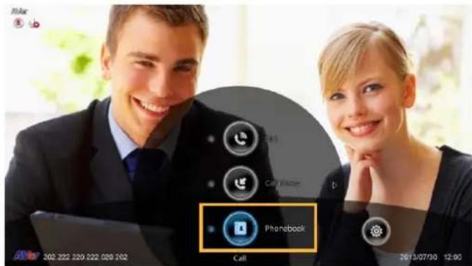
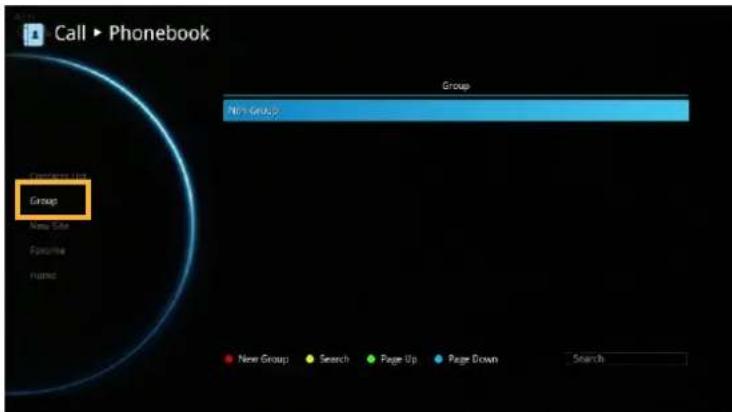
GROUP
Select Phonebook and press

Select Group and press

If you have lots of contacts, it is better to categorize them to groups such as client, vendor, company, branch, etc. to make the lookup easier.
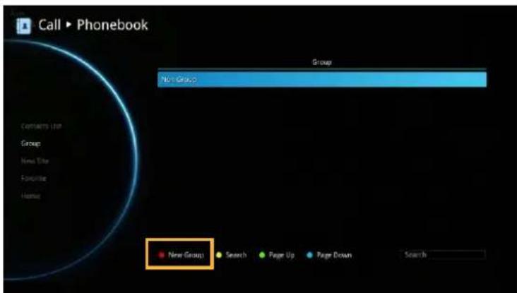
Create a New Group
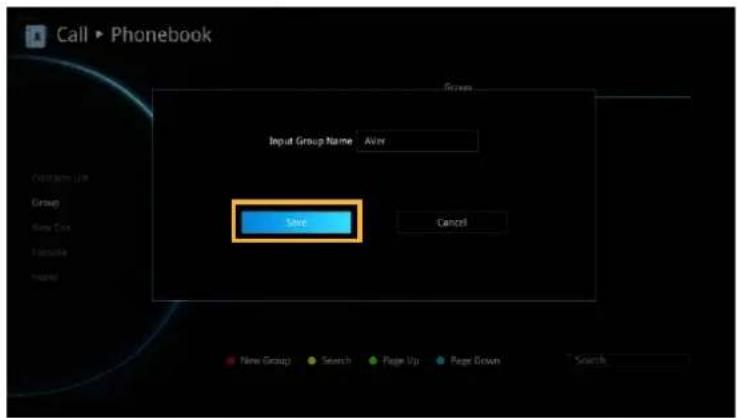
In the Group configuration screen, Press "Red" button on the remote controller to pop up the "Input Group Name" dialogue box.
Enter the group name that you want to create.
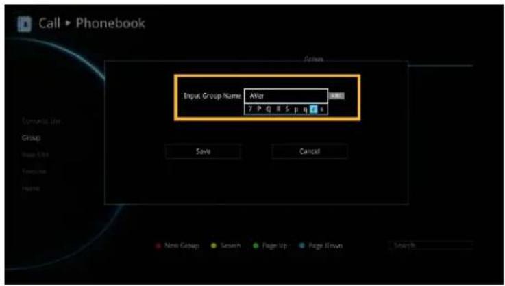
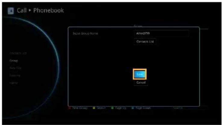
Select "Save" to save the new group. Or select "Cancel" to exit the "Input Group Name" dialogue box.
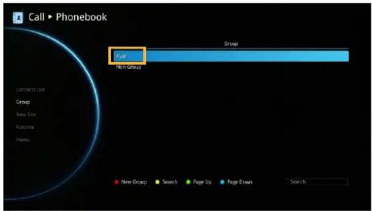
The new group name will be saved and displayed in the group list.
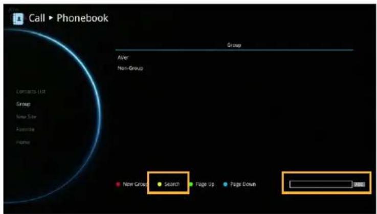
Search a Created Group
Press "Yellow" button on the remote controller and enter the group name that you want to search.
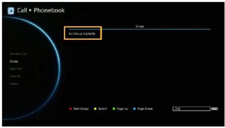
If the name you enter has not been created, the system will show you "No Group Available", please search again.
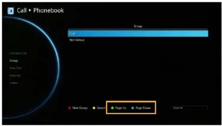
If the Group data are over one page, you can also press "Green" button or "Blue" button to Page Up or Page Down.
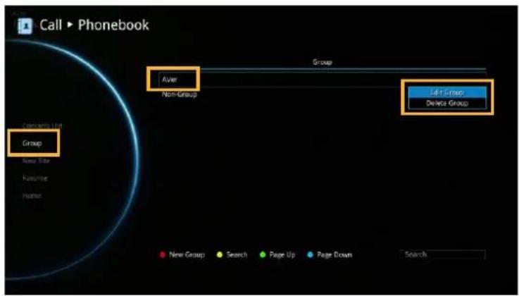
Edit Group
Select Phonebook | Group and press

Select the name you want to modify in the group list.
Select "Edit Group" and press

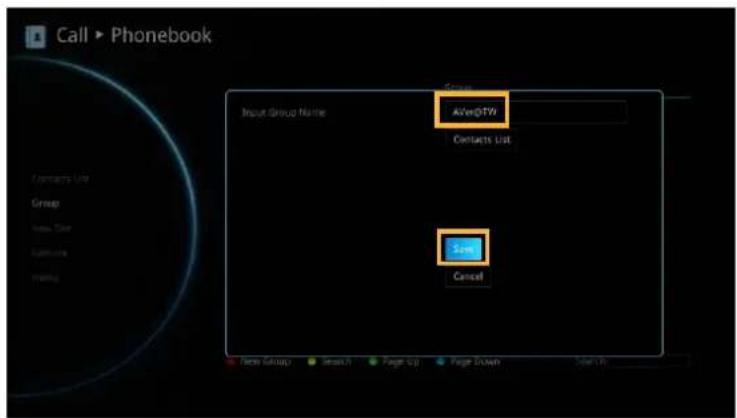
Modify the group name and select "Save" to save the revised group name.
The revised group name will be saved and displayed in the group list.
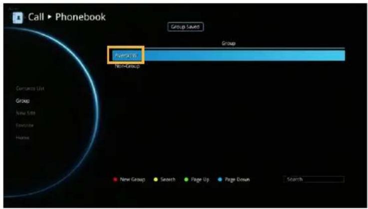
If the revised name is the same as
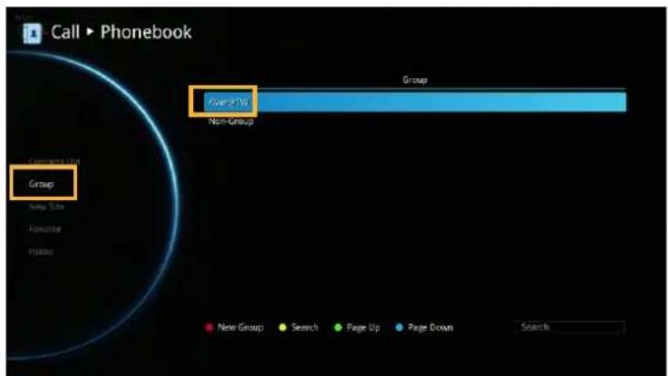
Add Contact from Group List
Select Phonebook | Group and press

Select the Group name you want to add to Contacts List.
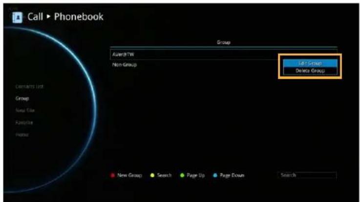
Select "Edit Group" and press

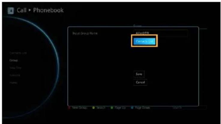
Confirm the Group Name what your want to add to the contracts list and then select "Contacts List".
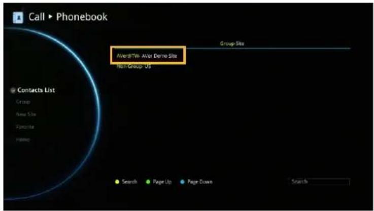
In the Group Site list, select the item that you want to add to the contracts list and then press "Red" button on the remote controller to save the selection.
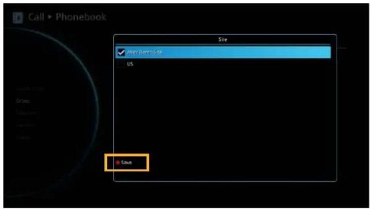
Select "Save" to save the Group name and added site to the contacts list.
The selected Group name and added site will be added into the contacts list.
Delete Group
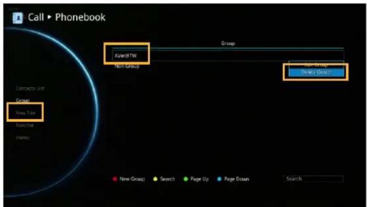
Select Phonebook | Group and press

Select the name you want to remove in the group list.
Select "Delete Group" and press

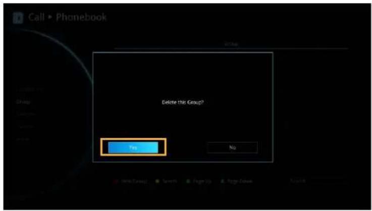
Select "Yes" to remove the selected group name and "Cancel" to cancel group name deletion.
The selected group name will disappear in the group list when deleted.
NEW SITE (CONTACT IN PHONEBOOK)
New Site allows you to create and edit the information to each site.
Add New Site
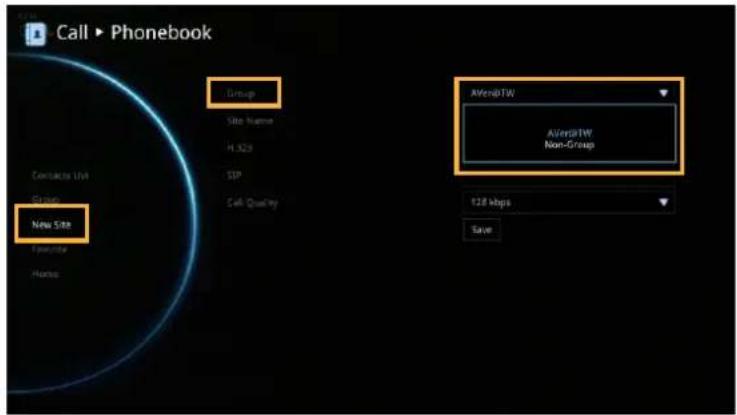
Select Phonebook | New Site and press

Select the Group name, if you don't want to add the entry into a group, please select "Non-Group" item.
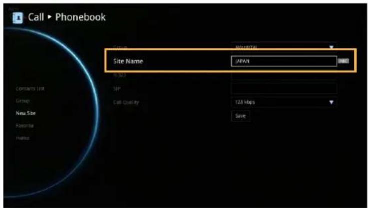
Select Site Name box. Enter the site name
with the remote controller and press

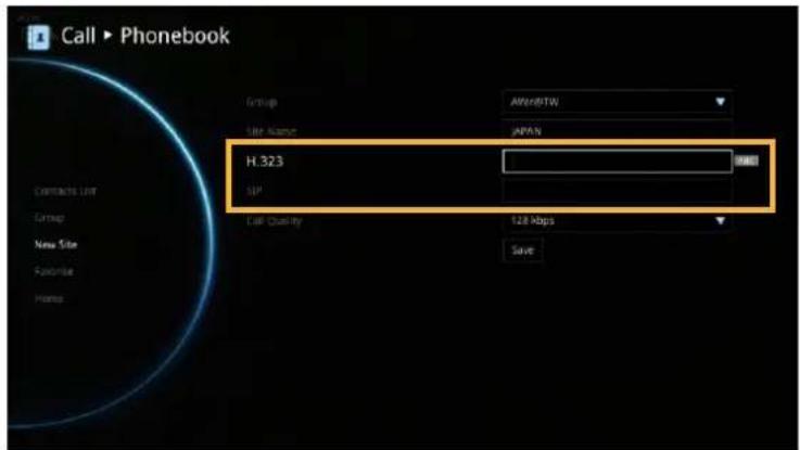
Enter the used call type information either H.323 or SIP.
Select the desired call quality value in the drop-down list.
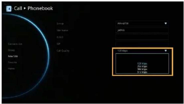
Select "Save" to store the newly added site contact.
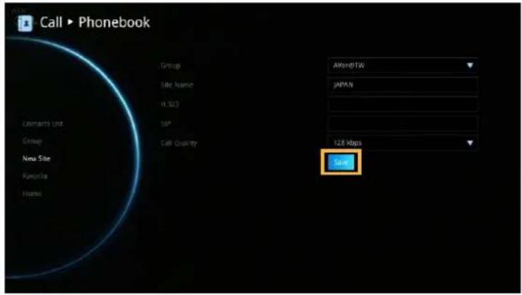
Edit New Site
Select Phonebook | Contacts List and press

Select the contact you want to modify and press ↻
Select "Edit Site" and press
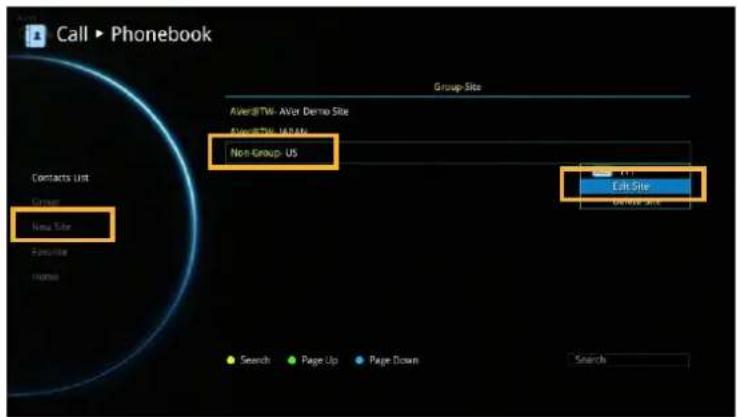
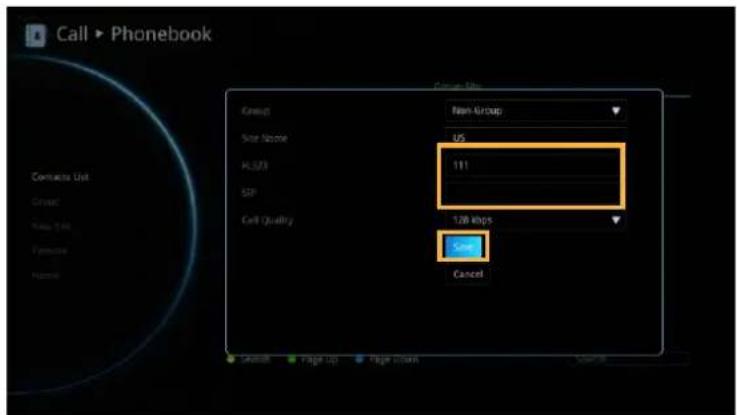
In the Edit Site screen, you many change the Group name, Site Name, H.323. SIP and Call Quality.
After making the changes, select "Save" to apply the new changes or "Cancel" to reserve the original settings.
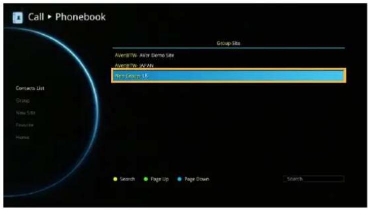
The saved changes will be shown in the Group Site list.
Delete New Site
Select Phonebook | Contacts List and press

Select the contact you want to delete and press
Select "Delete Site" and press
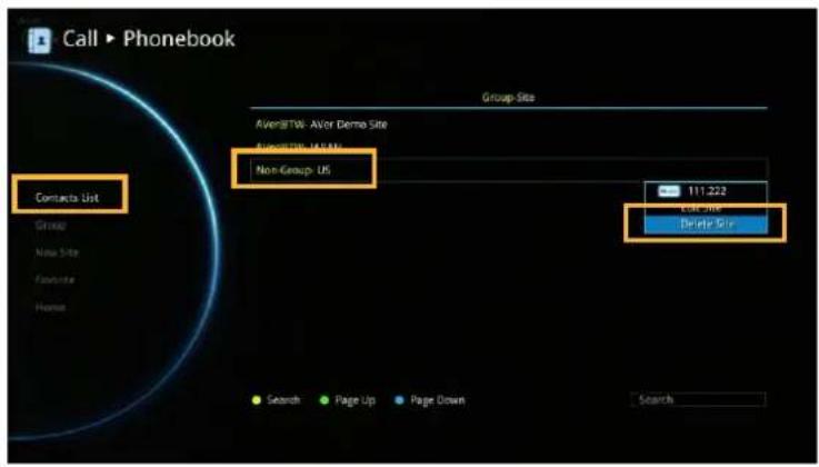
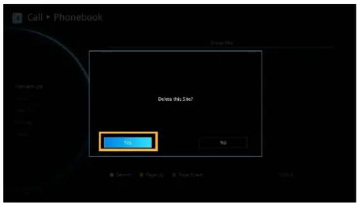
Select "Yes" to remove the selected contact and "No" to cancel contact deletion.
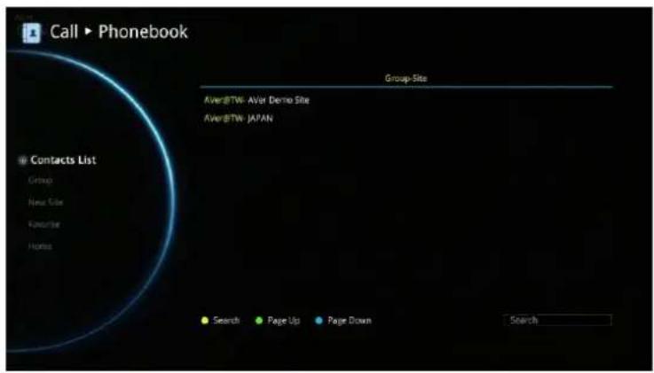
The selected contact will disappear in the Group-Site list when deleted.
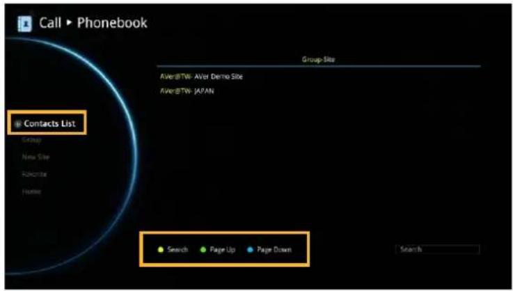
CONTACTS LIST
Contacts List shows you all of the contacts that you have created and saved. You can select the contact from the Contacts List directly for modifying or deleting. In the Contacts List configuration screen, you can also use the "Yellow" button on the remote controller to search the contact that you want. If the Group-Site over one page, you can also press "Green" button or "Blue" button to Page Up or Page Down.
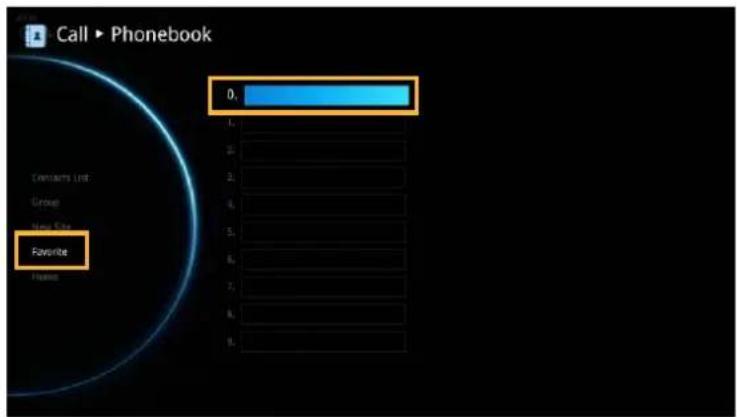
FAVORITE
AVer EVC allows you save up to 10 most used contacts in the favorite list.
Select Phonebook | Favourite and press
Select which line (0\~9) do you want to save the favorite contact and press
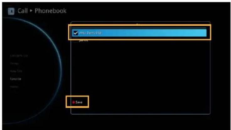
Select the contact from the pop-up Group Site list and press "Red" button on the remote controller to save the selection.
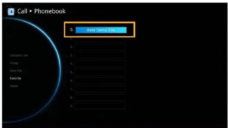
The item selected will be added into favorite list.
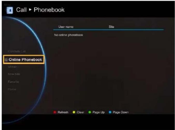
ONLINE PHONEBOOK
View the phonebooks are downloaded from LDAP server.
Call History
The Call History allows you to check the incoming/outgoing calls made and their status. You can also make a call by selecting it in the Call History list.
Call Status
Select Call History and press

The Call History will show you the IP address or the Site name with call type, Call Date/Time, Duration, and Call status. Refer to the table below to check the call status.
| Call Status | Answered | Failed |
| IN | ||
| OUT |
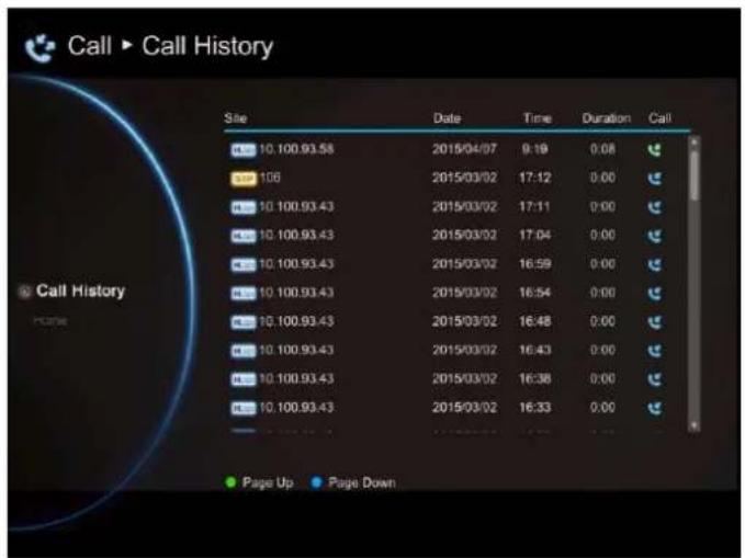
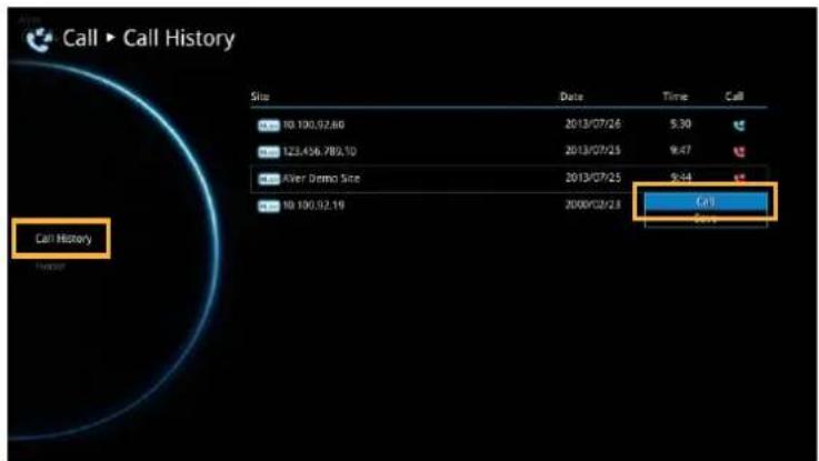
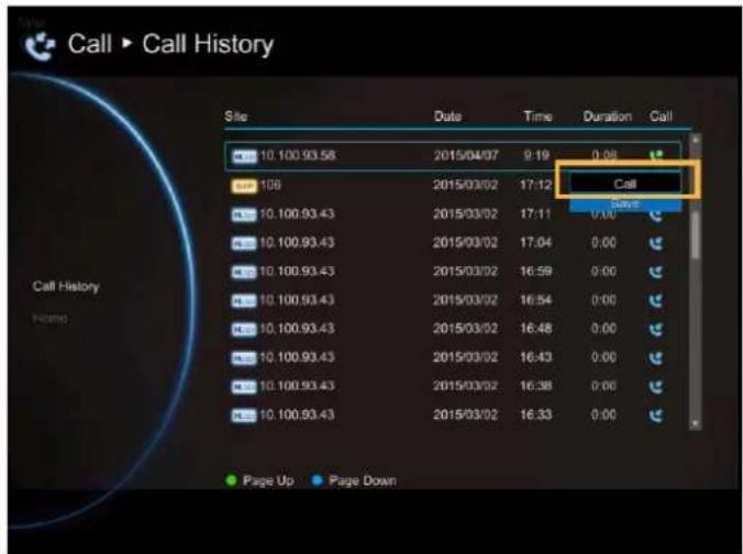
Make a Call From the Call History
Select Call History and press

Use the and buys to move the selection and scroll up and down in the cal history list.
Press 📁d select "Call" to make a call.
Or press 📞 button on the remote controller to make a call.
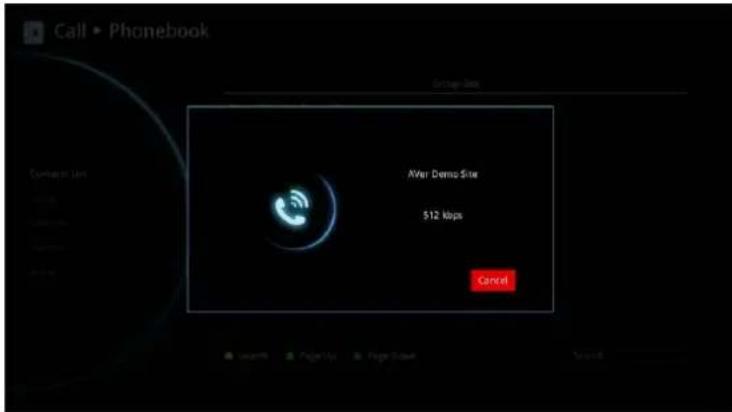
The call will be connected.
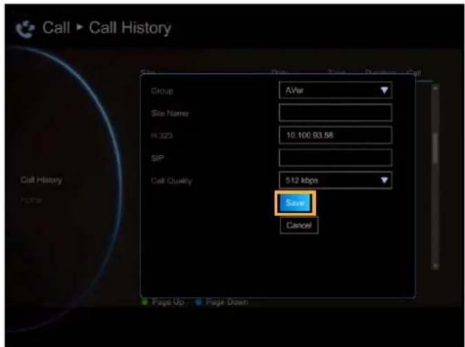
Make a Contact from the Call History
You can also save the call in/out information into your contacts list.
Select Call History and press
Use the □d but□s to move the selection and scroll up and down in the call history list.
Press 📂 and select “Save” to pop-up contact editing form. All relative information has filled in the contact form already based on the selected call entry from the Call History.
Confirm the Group selection then select "Save" to save the call entry into your contact.
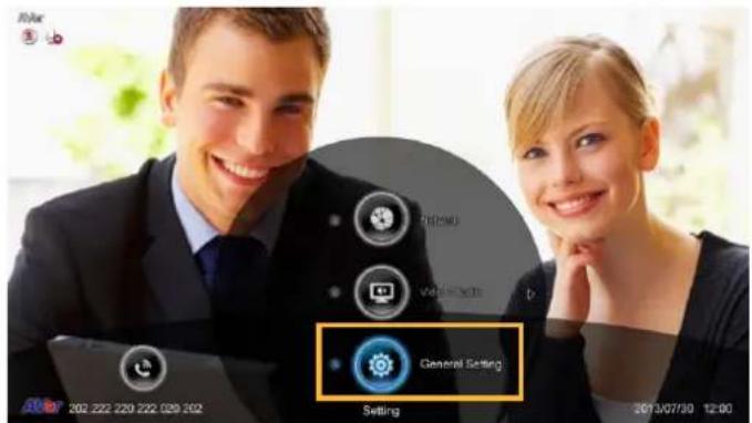
General Setting
The General Setting allows you to modify system setting, check the system info, test the system and watch recorded conference files.
CALL SETTINGS
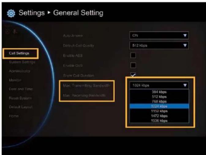
Call Setting allows you to enter or change your system's site name which will appear on the screen during the call session for the other party to identify you. Set the system to enable/disable auto answer, set the default call quality, and enable/disable Advanced Encryption Standard which ciphers the data to protect against unauthorized data access.
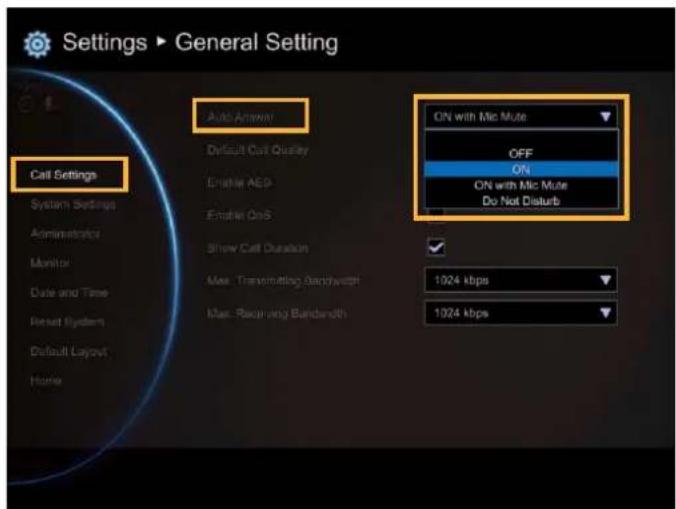
Auto Answer
Select General Setting | Call Settings and press

Select Auto Answer and press ⬇. In the Auto Answer drop-down list, select “OFF” to turn off Auto Answer. “ON” to answer the call automatically, “ON with Mic Mute” to automatically answer the call without microphone on, and “Do Not Disturb” to automatically reject incoming calls. If you are already in a conference, even if the Auto Answer is turned on, you also need to accept the next call manually.
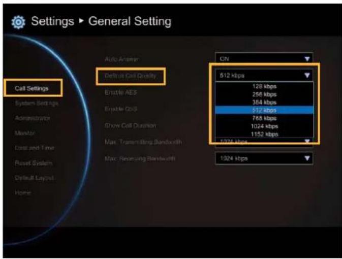
Default Call Quality
EVC main system supports 64k, 128k, 256k, 384k, 512k, 768k, 1024k, 1152k, 1472k, 1536k, 1920k, 2048k, 3072k, 4096k selection for default call quality. By default, it is set to 512k.
Enable/Disable AES
Advanced Encryption Standard (AES) encrypts the data that is being transmitted during a video conferencing to provide protection against unauthorized data access. Encrypted data can only be read with the device that also supports the AES standard. All parties on the call must support AES to use this feature, or else the data will not be encrypted.
Select General Setting | Call Settings and press Select the Enable AES check box to active this function.
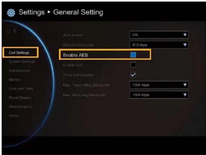
This function may be restricted and unavailable in some countries.
Enable/Disable QoS
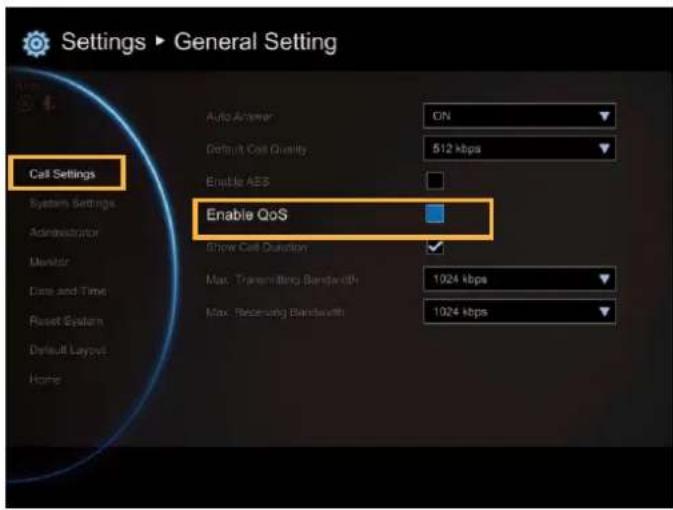
Quality of Service (QoS) provides different priority data flows to guarantee a certain level of performance in video conferencing data flow. To activate QoS, select General Setting | Call Settings and press Select the Enable QoS check box to active this function. By default, this function is disabled.
Show Call Duration
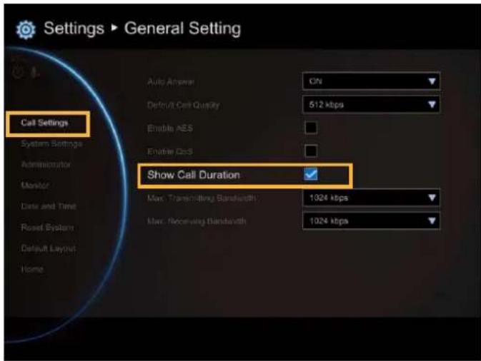
Enable/disable the call duration showing, by default, this function is enabled.
Max. Transmitting/Receiving Bandwidth
This function allows you to specify the maximum bandwidth of the outbound and inbound calls. Aver EVC system supports up to 4Mb.
SYSTEM SETTINGS
System Settings allows you to set Language, the time for Auto Power off and enable/disable Keypad Tone function for your main system.
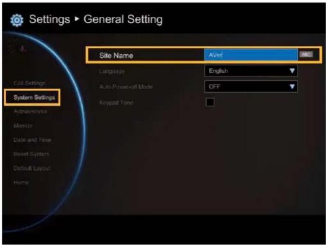
Site Name
Select General Setting | System Settings and press the site name is represented as name of this EVC system. Enter the site name as you wanted.
Language
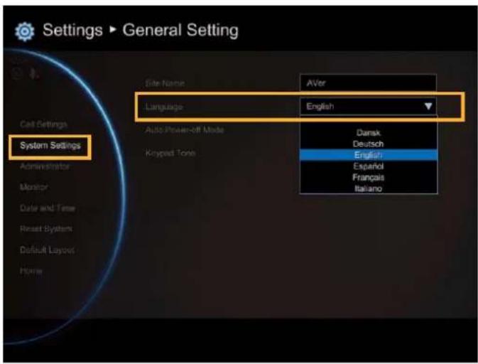
Select General Setting | System Settings and press
EVC main system supports up to 22 languages for your selection. Select the language from the drop-down list directly and the language for the system will turn into the selected language automatically.
Auto Power Off Mode
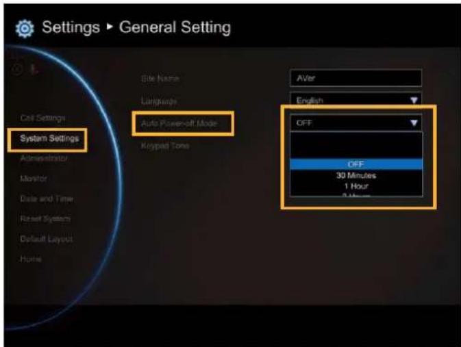
Auto Power Off Mode allows you to set the time to power off your system automatically after idling.
Select General Setting | System Settings and press 📄
Select the time from the Auto Power Off Mode drop-down list (OFF/30Minutes/1Hour/2Hours/3Hours/4Hours). Disable this function, please select "OFF". The function will completely turn off the system once you have set the auto power off time. To turn on the system you need to press the Power button on the man unit again.
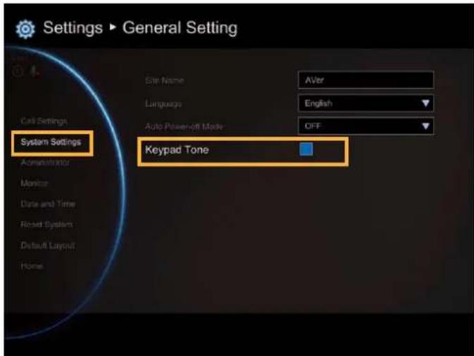
Keypad Tone
Keypad Tone allows you to enable/disable tone sounds when you are dialling a number using the remote controller.
Select General Setting | System Settings and press 📄
Select the Keypad Tone check box to enable the tone sounds. By default, this function is enabled.
ADMINISTRATOR
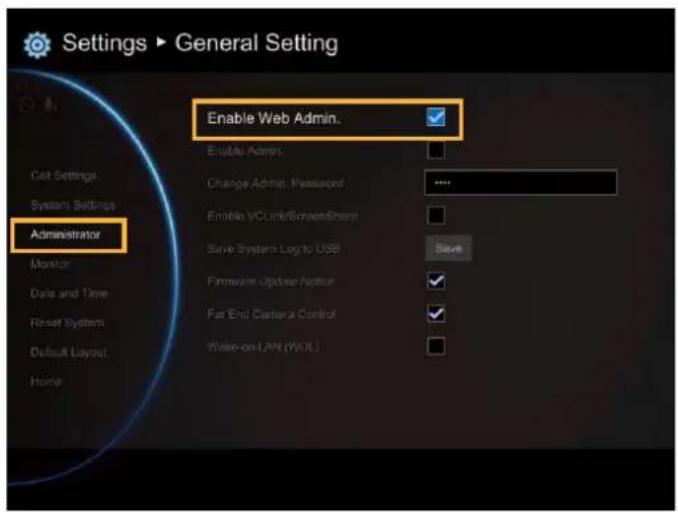
Enable Web Admin
Select General Setting | Administrator and press
Here allows you to enable administrator authority of Web Tool. When you access to Web Tool, a password is required. The default password is "1234".
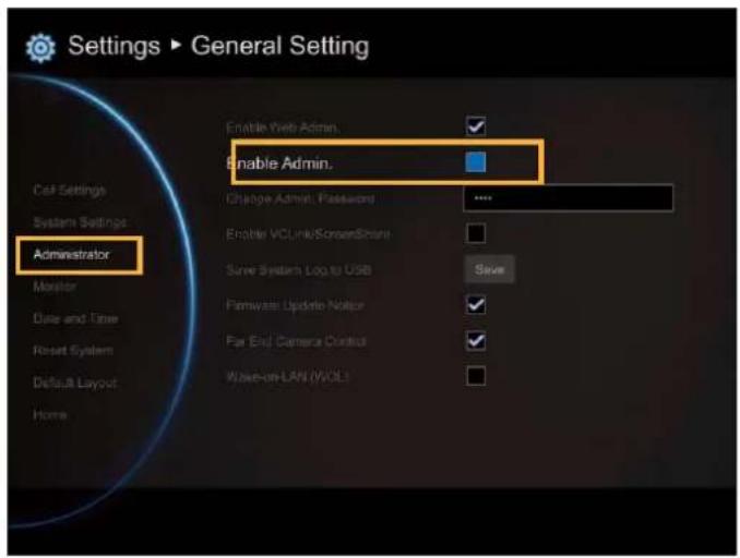
Enable Admin
Select General Setting | Administrator and press
Here allows you to enable authority of system administrator. When you want to setup system, a password is required. The default password is "1234".
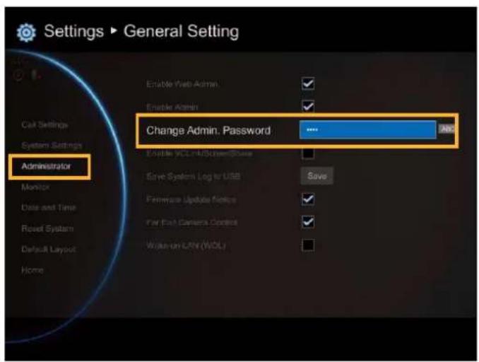
Change Admin. Password
Select General Setting | Administrator and press
Here allows you to change password of system administrator.
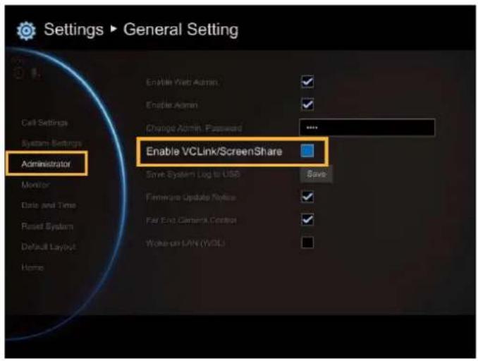
Enable VCLine/ScreenShare
Select General Setting | Administrator and press 📄
Here allows you to enable function of VCLink and ScreenShare.
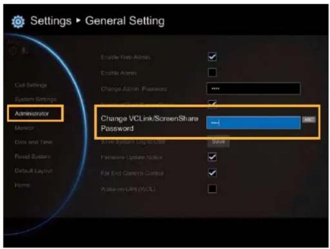
Change VCLine/ScreenShare Password
Select General Setting | Administrator and press
Here allows you to change password of VCLink and ScreenShare. The default password is "1234"
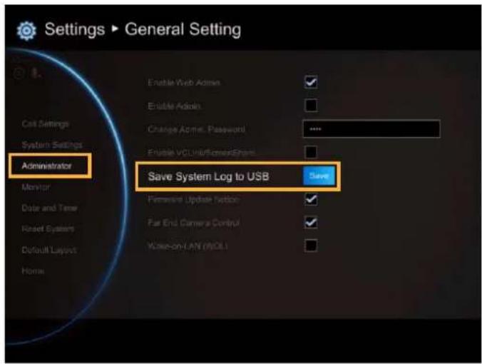
Save System Log
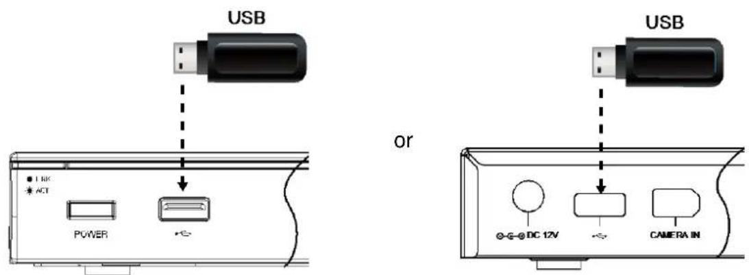
If you encounter unknown issues and are unsure of how to troubleshoot the unit, sending us the saved system log data to help us solve your problem faster.
Insert a USB Flash drive into the USB Port of the EVC main system. (Either on the front panel or back Panel)
Select "Run" located next to "Save System Log" to save the system log into your USB Flash drive.
After the file is saved, select "OK". Remove the USB Flash drive and insert it into your computer's USB port. Located the file message.tar.gz and send it to the technical support team.

message.tar.gz
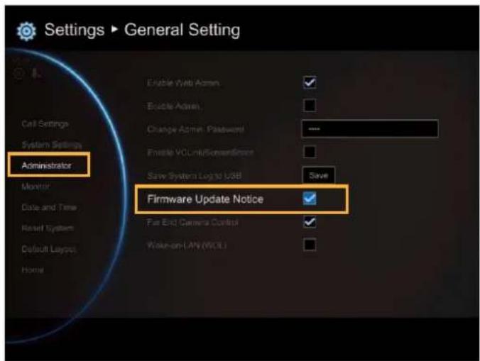
Firmware Update Notice
Select this function check box to enable firmware updated notice function. By default, this function is enabled.
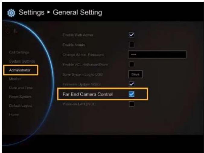
Far End Camera Control
Select the "Far Control of Near Camera" check box to enable the far site to control your camera. By default, this function is enabled.
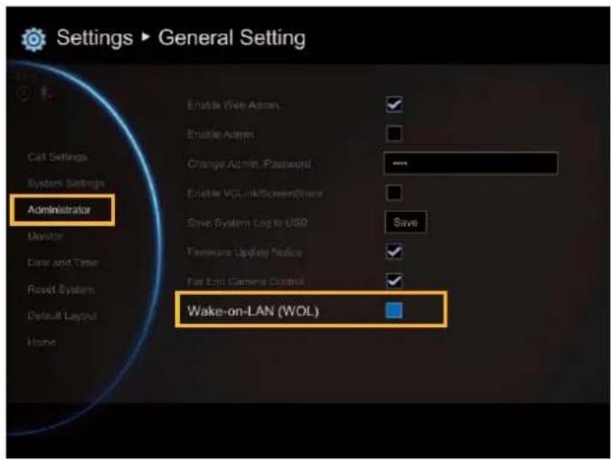
Wake-On-LAN (WOL)
Wake-on-LAN is an Ethernet computer networking standard that allows your computer to be turned on or awakened by a network message. By default, this function is disabled.
MONITOR
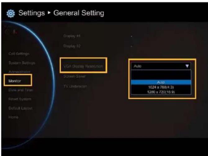
EVC main system allows you to connect dual monitor. In the Monitor configuration screen, you can configure the Aspect Ratio and Screen Saver to each monitor.
Select General Setting | Monitor and press
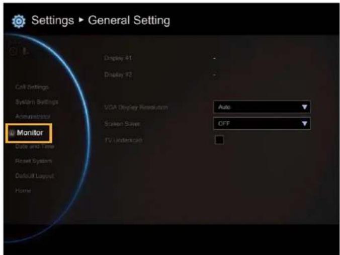
Select the Monitor Aspect Ratio (Auto/4:3/16:9) that you want from the drop-down list and press
. If you want the system to detect the right setting automatically, please select "Auto".
Select the Screen Saver time (OFF/10 Minutes/20Minutes/30Minutes/60Minutes) from the drop-down list and press . You can select "OFF" to disable this function or define a standby mode time.
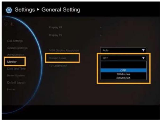
The screen will turn black when the system is in standby mode. Press any button on the remote controller to wake up the system.
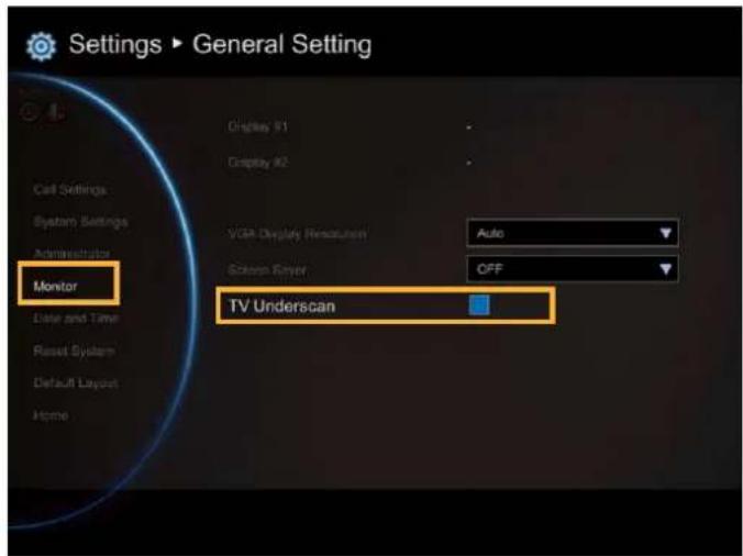
TV Underscan
For older type TVs/CRT monitors, this function can help to auto adjust screen view when the GUI is exceeded the monitor view range.
DATE AND TIME
Date and Time allows you to set the Date and Time formats, adjust the time setting and change the Time zones around the world and countries.
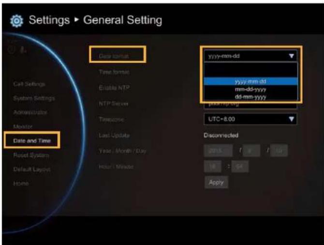
Date Format
Select General Setting | Date and Time and press 📂
Select the Date Format (yyyy-mm-dd/mm-dd-yyyy/dd-mm-yyyy) you prefer from the drop-down list.
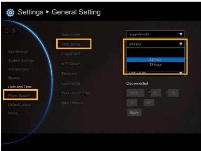
Time Format
Select General Setting | Date and Time and press 📄
Select the Time Format (24-hour/12-hour) you prefer from the drop-down list.
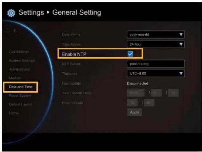
Enable NTP
Network Time Protocol (NTP) is a protocol that is used to synchronize computer clock times in a network of computers. Select the Enable NTP check box to make your computer time the same as the network time.
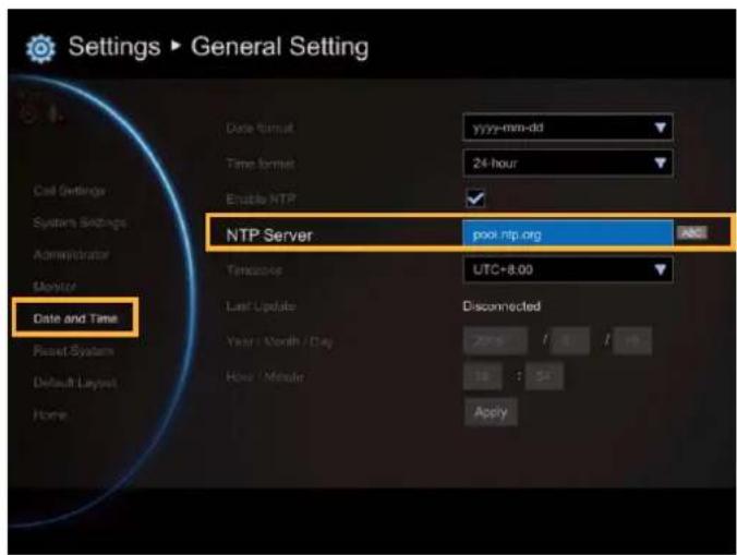
NTP Server
The Network Time Protocol (NTP) allows administrators to synchronize all network computers to a main server. This keeps all network machine clocks on the same time. Enter the NTP Server name that you want to follow.
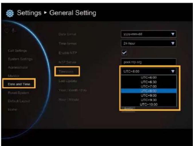
Timezone
Timezone allows you to adjust the time when you are in a different country or area so that you can keep the same time with your original area. Most of the time zones on land are offset from Coordinated Universal Time (UTC) by a whole number of hours (UTC-12 to UTC+14).
Year and Hour
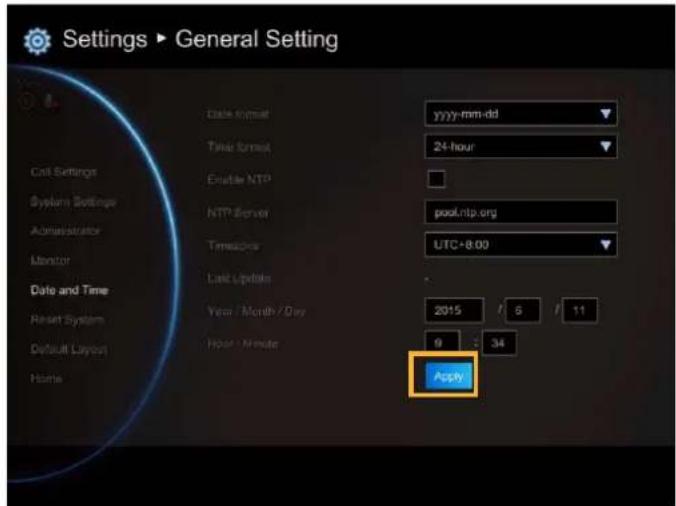
Enter the date and time including year, month, day, hour and minute that you want to show on the present system.
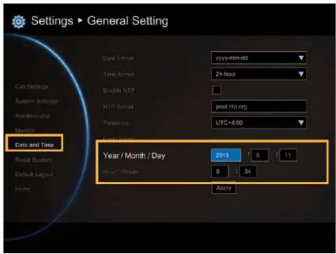
Select "Apply" to active your settings.
RESET SYSTEM
The Reset System allows you to reset your main system to factory settings, which will clear phonebook entries and call history. Make sure to back up the information before resetting the system.
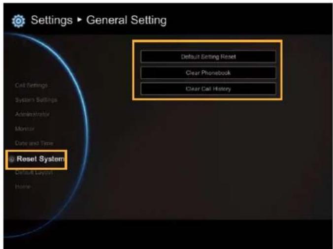
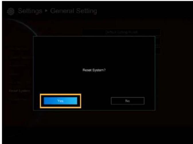
Default Setting Reset: LAN configuration, video/audio codec selection, call settings and so on will be reset. Click "Yes" to reset your system to factory default values.
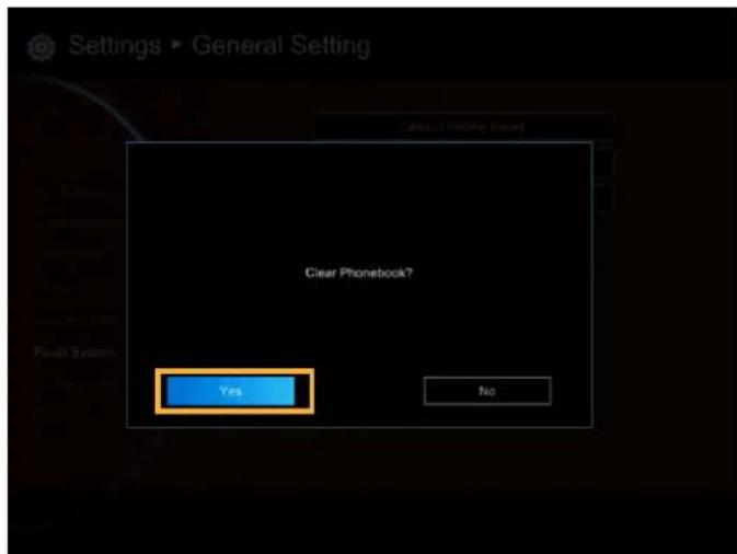
Clear Phonebook: All the phonebook entries saved in the system will be deleted.
Click "Yes" to delete all content of your phonebook.
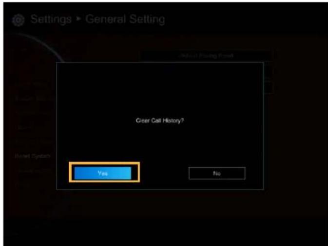
Clear Call History: All the incoming and outgoing call records will be deleted. Click "Yes" to delete all calling information of the call history.
DEFAULT LAYOUT
You can select the layout for call conference. There two type of layout – Layout without content and Layout with content.
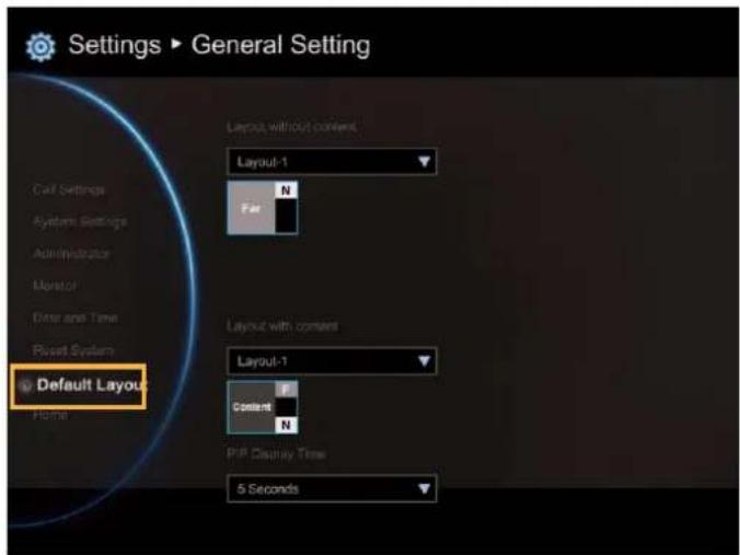
Layout without content: Only display call video, no content share screen.
There 4 layouts can be chosen. During the call conferencing, the display layout will be the layout that you has chosen.
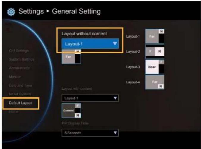
Layout with content: display call video and content share screen.
There 6 layouts can be chosen; but only 2 layouts include content share screen. During the call conferencing, the display layout will be the layout that you has chosen.
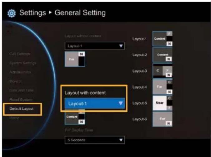
PIP Display Time: When conference call is connected, screen is displayed in PIP mode. You can manually setup PIP mode display time. The default is 5 seconds.

natural_image
Group of business professionals in a modern office setting, smiling and seated at a desk with laptops (no visible text or symbols)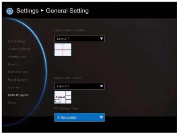
Video/Audio
In Video/Audio configuration screen, you can set the MIC gain level, select the preferred video and audio codecs and adjust the camera functions.
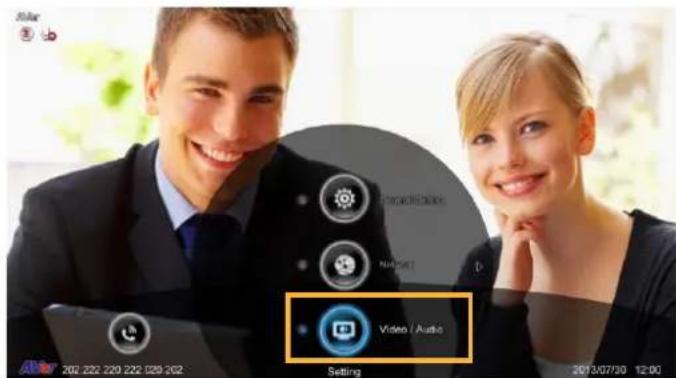
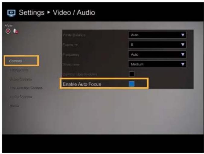
CAMERA
Camera allows you to set the White Balance, Exposure and Frequency for your camera.
White Balance
Whit balance is a camera setting that adjusts for lighting in order to make white objects appear white in photos.
Select Video/Audio | Camera and press

Select the White Balance type from the drop down list. EVC main system supports up to 5 types of white balance for your selection.
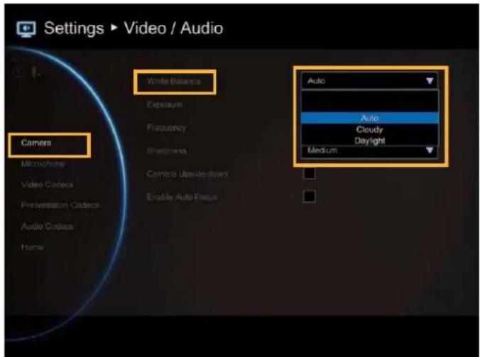
Auto: Most cameras default to automatic white balance. It makes white objects bright white and alter all the other colors to match.
Cloudy: You can use the Cloudy white balance setting instead of auto on a cloudy day. This allows the camera to compensate for blueness in the shadows, warming up the scene to better match what your eye would see.
Daylight: You can use Daylight settings only when shooting in very bright sunlight, as it can produce bluish results on overcast days.
Fluorescent: You can use Fluorescent setting to cancel out the green or blue cast, which can produce sickly-looking results on human skin.
Tungsten: This setting assumes a color temperature of around 3,200k and is suitable for most tungsten lamps that normally emit a yellow light. This is usually used to correct for the same color cast.
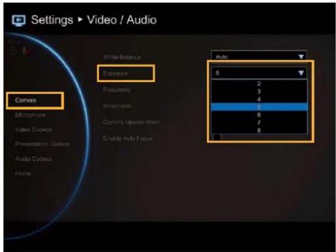
Exposure
A photograph's exposure determines how light or dark an image will appear when it is beer captured by your camera. Select the exposure level you prefer from 1 to 9 or auto.
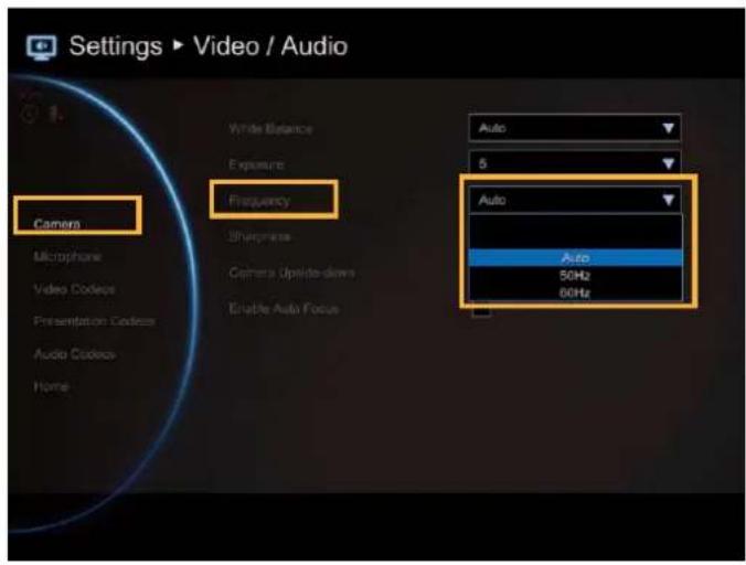
Frequency
Select the correct frequency setting (Auto/50Hz/60Hz/OFF) form the Frequency drop-down list.
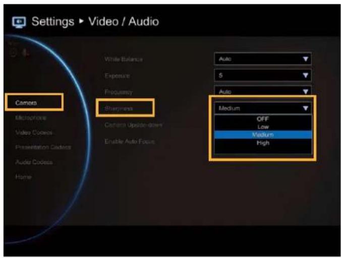
Sharpness
Adjust camera sharpness. The more sharpness the screen image more easy has noise.
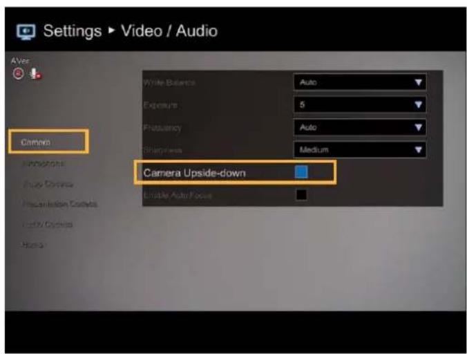
Camera Upside-down
When camera is handed at up-side-down position, enable Camera Upside-down to flip the image view.
Enable Auto Focus
Enable/disable auto focus function.
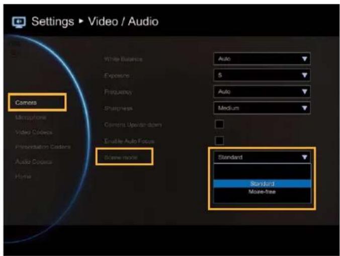
Scene Mode
Standard: No any effect adjustment on screen view.
Moire-free: To reduce moire if moire screen is happened.
MICROPHONE
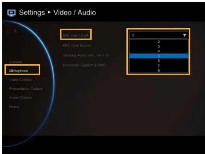
EVC main system allows you to adjust the MIC Gain Level up to 9 for proper MIC volume to improve audio reception on the microphone (s).
MIC Gain Level
Select Video/Audio | Microphone and press

Adjust the MIC Gain Level form the drop-down list.
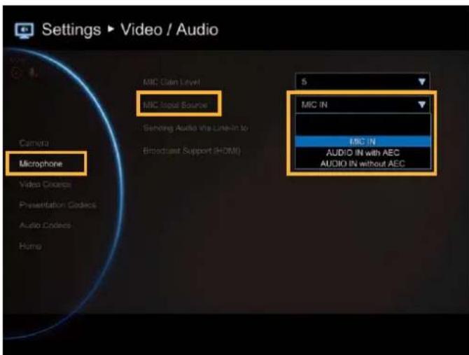
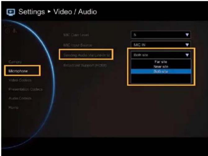
MIC Input Source
Select the source of the microphone from the MIC in, Audio IN with AEC, or Audio IN without AEC. If you connect a microphone in AUDIO IN port, we recommend selecting Audio in selection to avoid the echo issue.
Sending Audio Via Line-in to
Send the audio through the audio device that is connected at audio input port of EVC to selected site(far, near, or both).
If MIC Input Source is MIC in, you can choose far, near or both site can hear the audio sound. If MIC Input Source is Audio in, only "far site" can be heard the audio sound.
[Note] When audio input port is connected with audio device and enable "Sending Audio Via Line-in to" function, the AVer MIC is disabled.
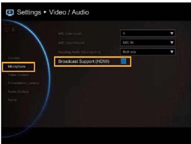
Broadcast Support(HDMI)
This function allows you to hear own talking voice during video conferencing through the stream media device that is connected on HDMI port of EVC main unit.
In MIC Input Source, please select "MIC In".
If the stream media device didn't connect to HDMI port of EVC main unit, it will cause howling when voice come out from TV or speaker.
VIDEO/AUDIO CODECS
You can specify the Video/Presentation/Audio Codecs in Video Codecs, Presentation Codecs, and Audio Codecs configuration screens.
Select Video/Audio | Video Codecs for Video Codecs configuration, Video/Audio | Presentation Codecs for Presentation Codecs, or Video/Audio | Audio Codecs for Audio Codecs configuration and press
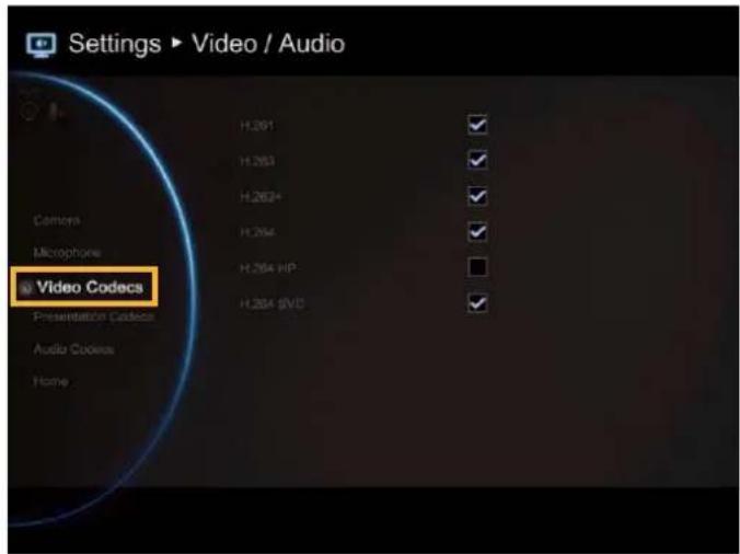
Select the Video/Presentation/Audio Codecs to specify the codecs you want to support. While the EVC supports the H.323 standard coding algorithm, each codec has unique properties and performs best given a certain set of circumstances.
For Video : H.261, H.264, H.263+, H.263, H.264HP, H264SVC
[Note]
- H.261 is always mark by default.
- H.264SVC only work with AVer EVC system and default is disabled.
For Presentation: H.263, H.263+, H.264, H.264HP, H264SVC
For Audio: G.728, G.722.1C, G.722.1*, G.722, G.711.
*:G.722.1/G.722.1C, licensed from Polycom®
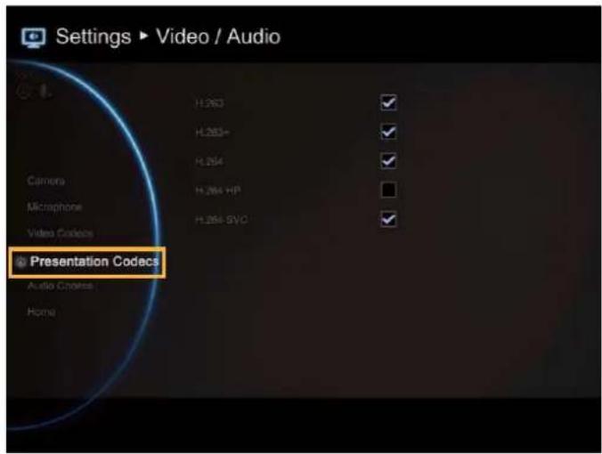
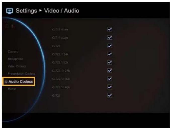
Please contact system administrator if you have any question on these codecs.
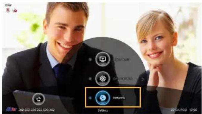
Network
Network allows you to set the SIP Server, Gatekeeper, Firewall and LAN
Configurations. Before configuring Network and Firewall, please refer to page 69 – Scenarios for LAN connection and follow the instructions of your actual network connection scenario.
LAN CONFIGURATION
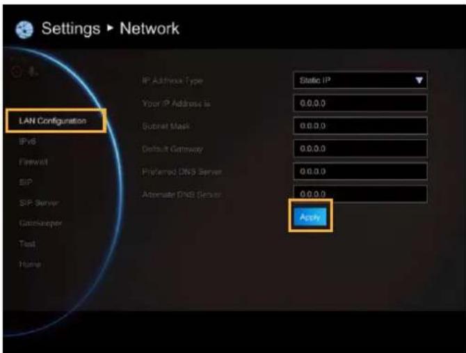
AVer EVC supports IPv4 and IPv6 internet protocol for your configuration. IPv4 is the most widely deployed internet protocol used to connect devices to the internet. IPv4 uses a 32-bit address scheme, written in decimal as four numbers separated by periods. Each number can be zero to 255. For example, 192.168.0.1 could be an IP address.
Select Network | LAN Configuration and press
Configure the following relative items to setup the LAN Configuration.
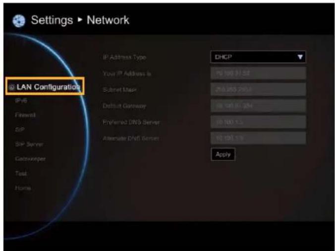
IP Address Type
DHCP: Configure the system to automatically obtain an IP address from the DHCP server.
Static IP: Configure the system to use the assigned IP address. Select this when the public IP address is available.
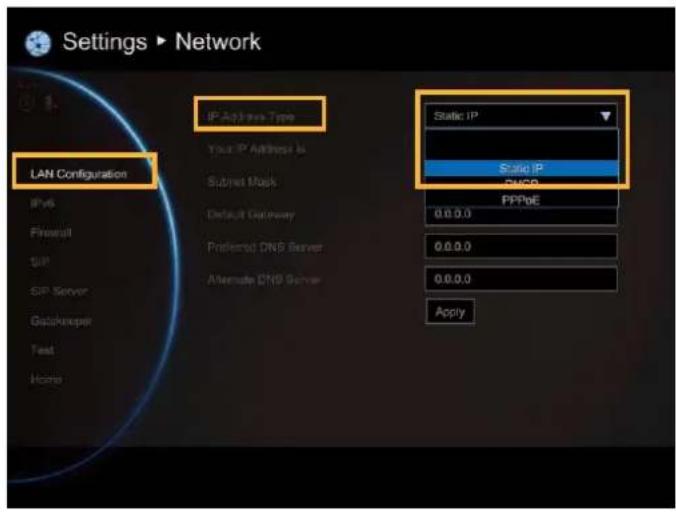
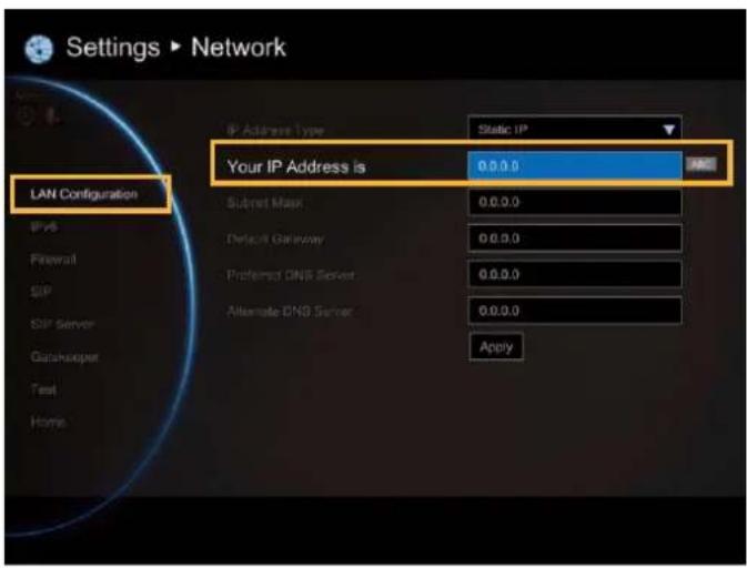
Your IP address is
Show the current IP address; enter into when you need to configure your IP address manually.
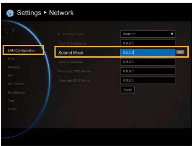
Subnet Mask
Show the designated IP address routing prefix; enter the subnet mask address when the system does not automatically obtain the subnet mask
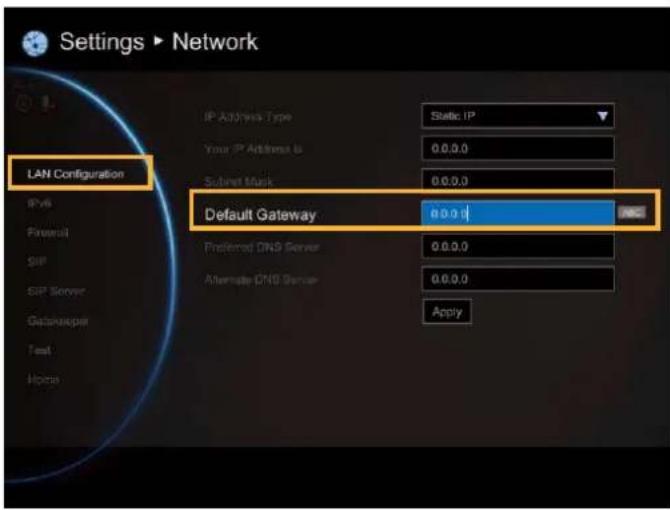
Default Gateway
A gateway is a network point that acts as an entrance to another network. Enter the gateway address when the system does not automatically obtain the gateway.
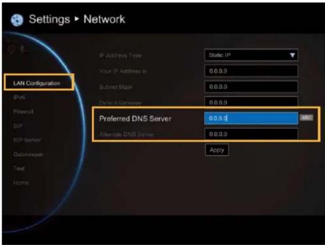
Preferred/Alternate DNS Server
Domain Name System (DNS) servers convert human friendly names (for example: www.example.com) to IP addresses (218.77.272.166) that let machines be found on the network. The preferred DNS server is the one your computer asks first. The alternate is a backup. Enter the Preferred and Alternated DNS Server address.
After finishing all settings, select "Apply" to active the changed settings.
LAN CONFIGURATION (IPV6)
IPv6 is an evolutionary upgrade to the Internet Protocol. IPv6 will coexist with the older IPv4 for some time. IPv6 addresses are 128-bit IP address written in hexadecimal and separated by colons. An example IPv6 address could be written like this: 300E:1389:3030:72EB:1D71:414B:1079:6AF3. Some types of addresses contain long sequences of zeros that can be compressed (the address of fc00:0000:0000:0000:0000:0000:0000:0001 can be compressed to fc00::1.
Select Network | LAN Configuration (IPv6) and press
Configure the following relative items to setup the LAN Configuration (IPv6).
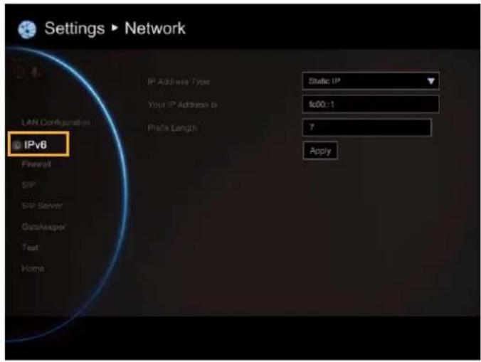
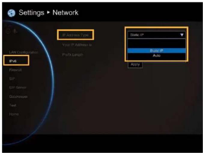
IP Address Type
Static IP: Configure the system to use the assigned IP address. Select this when the public IP address is available.
Auto: Obtain the dynamic IP address automatically.
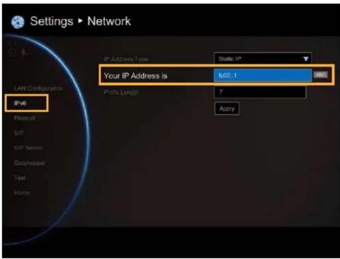
Your IP Address is
Show the current IP address; enter into when you need to configure your IP address manually.
Prefix Length
Prefix Length allows you to place as many IPv6 devices as the underlying network medium allows.
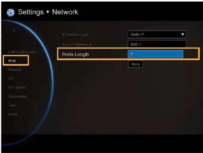
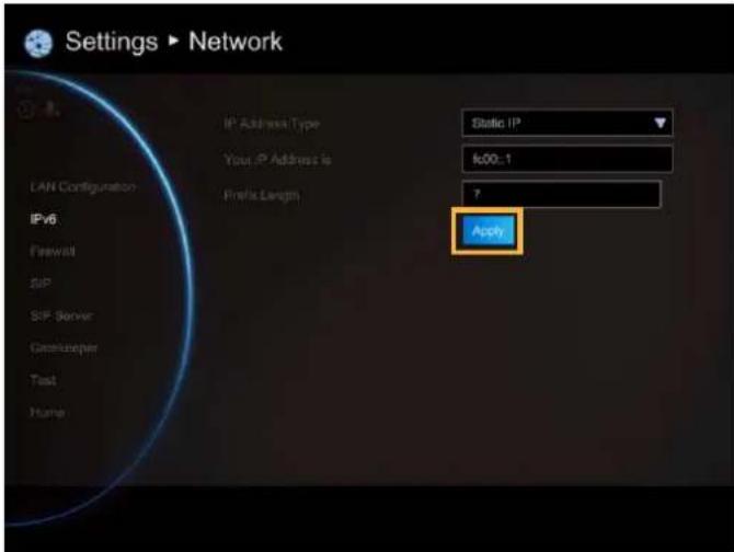
After finishing all settings, select "Apply" to active the changed settings.
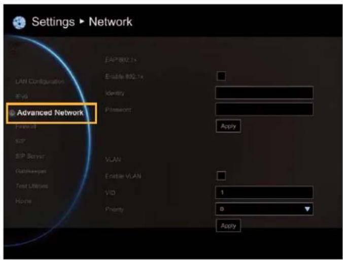
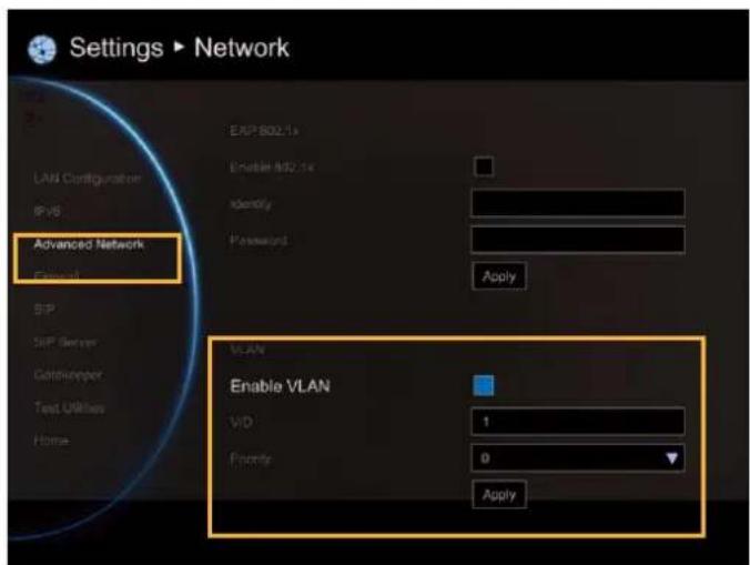
ADVANCE NETWORK
Configure 802.1x and VLAN settings.
Select Network | Advance Network and press

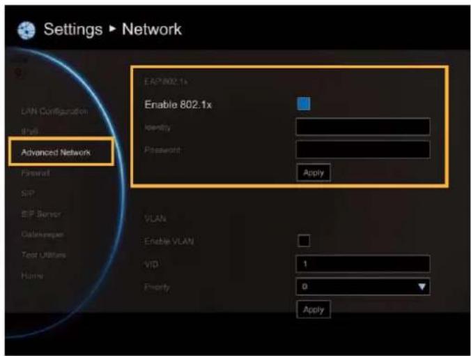
EAP 802.1x
■ Enable 802.1x: Enable/disable 802.1x protocol. IEEE 802.1X is an IEEE Standard for port-based Network Access Control (PNAC). It provides an authentication mechanism to devices wishing to attach to a LAN or WLAN.
■ Identity: Enter the ID for 802.1x authentication.
■ Password: Enter 802.1x's authentication password.
Click Apply to save and active the settings.
VLAN
■ Enable VLAN: Enable/disable VLAN function. A virtual LAN (VLAN) is any broadcast domain that is partitioned and isolated in a network at the data link layer.
■ VID(802.1q): Enter port for VLAN.
■ Priority(802.1p): Assign VLAN packet's priority.
Click Apply to save and active the settings.
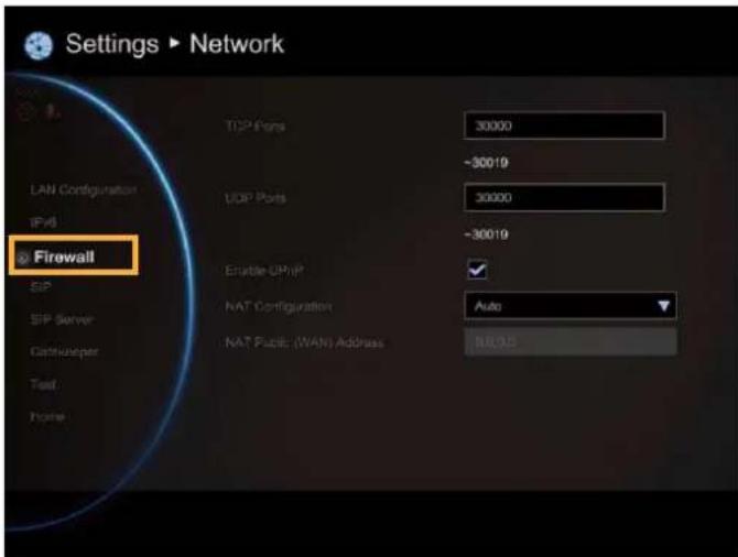
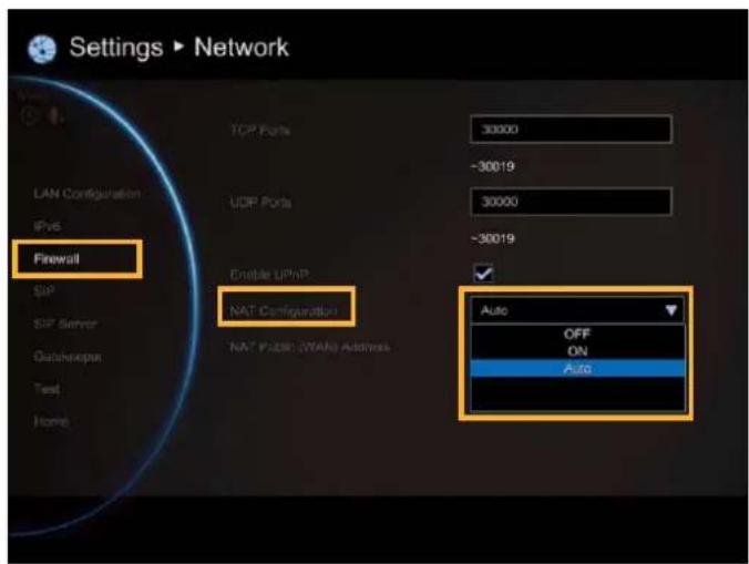
FIREWALL
Configure the following items to setup the Firewall.
Select Network | Firewall and press

Configure the following relative items to setup the Firewall.
TCP/UDP Ports
By default, the system communicates through TCP/UDP ports in the range from 30000 to 30019. You can specify the range for your specific network environment.
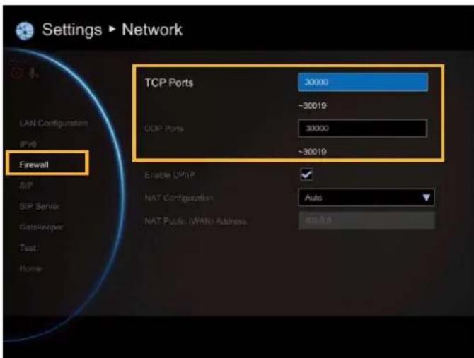
You must configure your firewall to allow inbound/outbound traffic through TCP ports 1720/1719 for H.323 call setup.
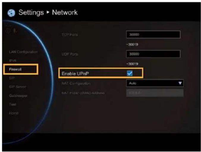
Enable UPnP
Enable/disable UPnP function.
NAT Configuration
AVer EVC supports NAT systems that use the internal IP addresses to communicate with other devices outside the LAN.
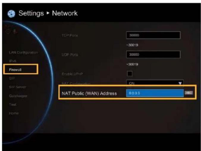
NAT Public (WAN) Address
The NAT public address must be entered when you enable the feature on NAT configuration.
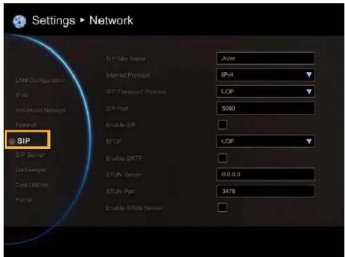
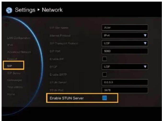
SIP
Session Initiation Protocol (SIP) allows you around the world to communicate using your supported devices over the Internet.
Select Network | SIP and press

Configure the following relative items to setup the SIP.
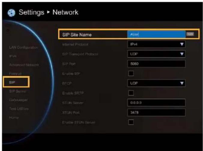
SIP Site Name
Enter the SIP site name for others to identify. The SIP site name may be the same or different then the domain for Web activity.
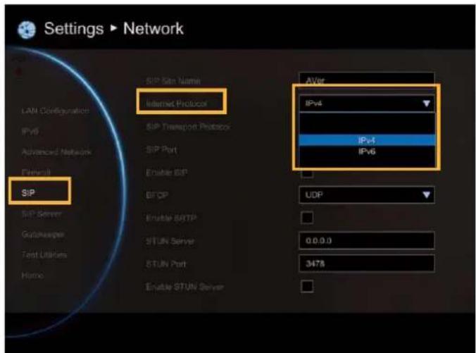
Internet Protocol
Select internet protocol check box to enable IPv4 or IPv6 protocol using.
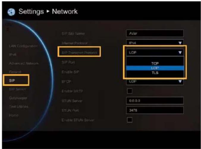
SIP Transport Protocol
Select the SIP Transport Protocol type from the drop-down list for using. There are two types of Internet Protocol (IP) traffic. They are Transmission Control Protocol (TCP) and User Datagram Protocol (UDP). To ensure proper connection, verify if both calling parties are using the same transport protocol. By default, it is set to UDP.
TCP: TCP is connection oriented. Once a connection is established, data can be sent bidirectional.
UDP: UDP is a simpler, connectionless Internet protocol. Multiple messages are sent as packets in chunks using UDP.
TLS: TLS is a cryptographic protocols designed to provide communications security over a computer network. SIP payloads will be encrypted to prevent malicious or unwanted modifications. NAT-traversal can be achieved by TLS connections since SIP payloads will not be altered by NAT-enabled routers
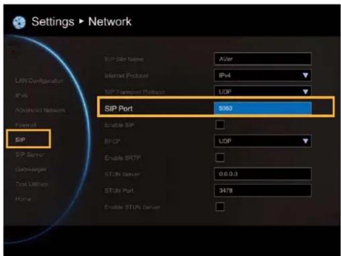
SIP Port
Change this value only if you use specific settings in your network system. By default, the SIP port is set to 5060.
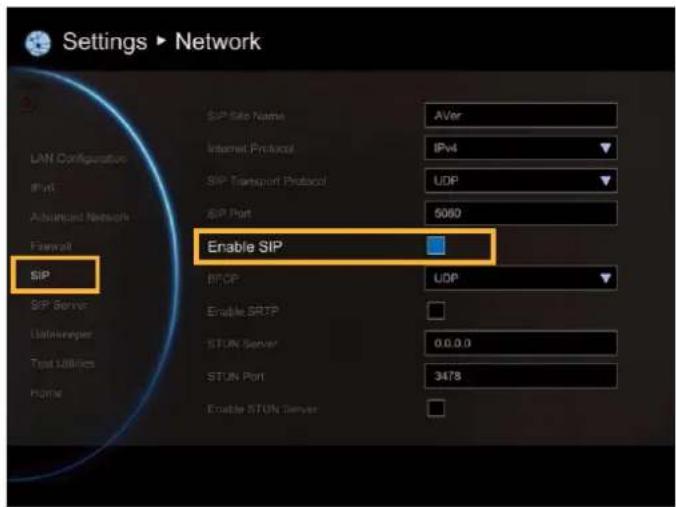
Enable SIP
Select Enable SIP check box and press activate/deactivated using SIP.

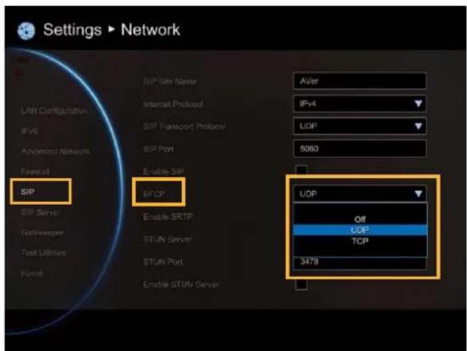
BFCP
Enable presentation sharing function in SIP. It allows you to share the presentation file screen to other caller in video conference meeting.
If connection is not so stabled, use TCP mode can offer a reliable connection to prevent unexpected disconnection and behaviors due to packet losses.
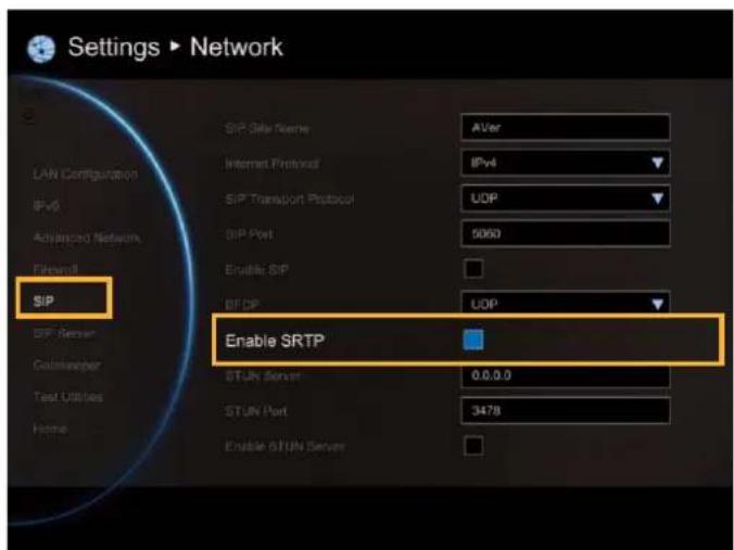
Enable SRTP
Through SRTP, RTP payloads will be encrypted to prevent sniffer, and hence secure communication between users.
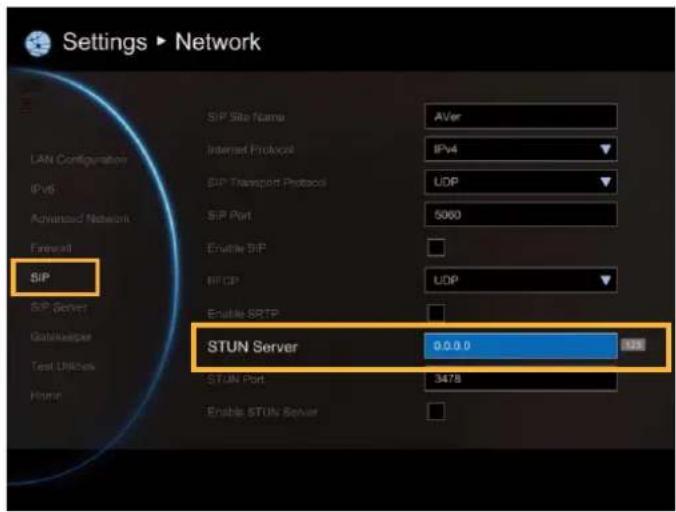
STUN Server
STUN (Session Traversal Utilities for NAT) is a standardized set of methods and a network protocol to allow an end host to discover its public IP address if it is located behind a NAT.
Enter IP address of SIP NAT traversal server.
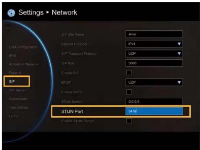
STUN Port
Enter port number of STUN server.
Enable STUN Server
Mark to enable STUN server function.
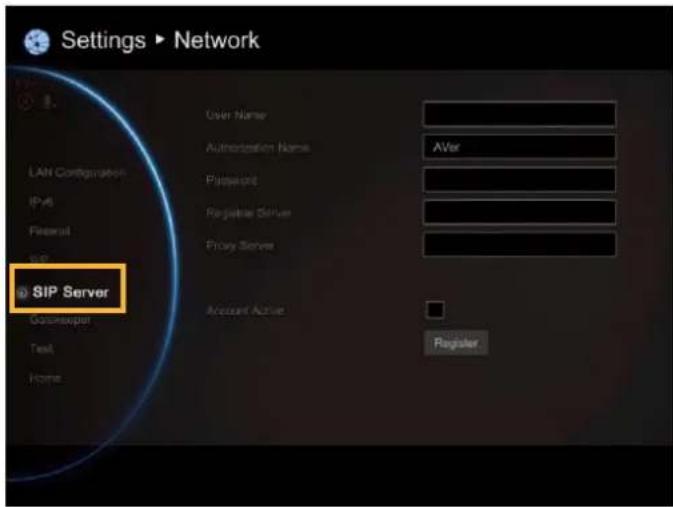
SIP SERVER
A typical SIP session involves a client requesting a session with a SIP server. After the request is received, the SIP server returns a response to the user indicating the availability of the session.
Select Network | SIP Server and press

Configure the following relative items to setup the Server.
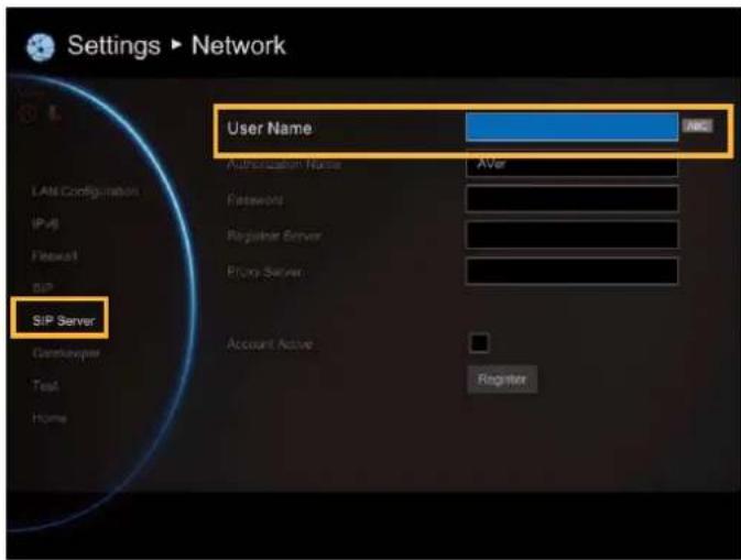
User Name
Select Terminal Name and press 📄enter user name.
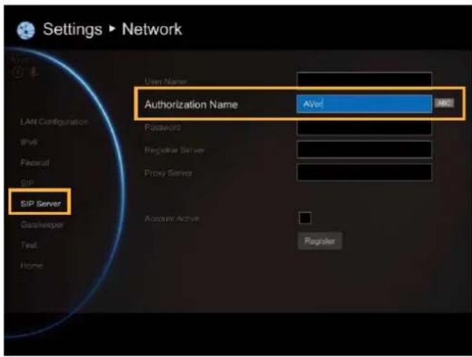
Authorization Name
Select Terminal Name and press enter authorization name.
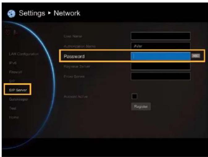
Password
Select Password and press ↕ enter using password.
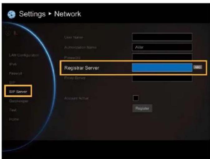
Registrar Server
Registrar Server accepts registrations from users and places these registrations, (which is essentially location information), in a database known as a location service. Enter the Registrar Server name that you want to use.
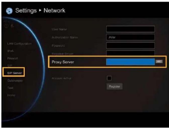
Proxy Server
Proxy Server is computing device (typically a server) that interfaces between data processing devices and others within a communications network. These devices may be located on the same local area network or an external network. Enter the used Proxy Server name.
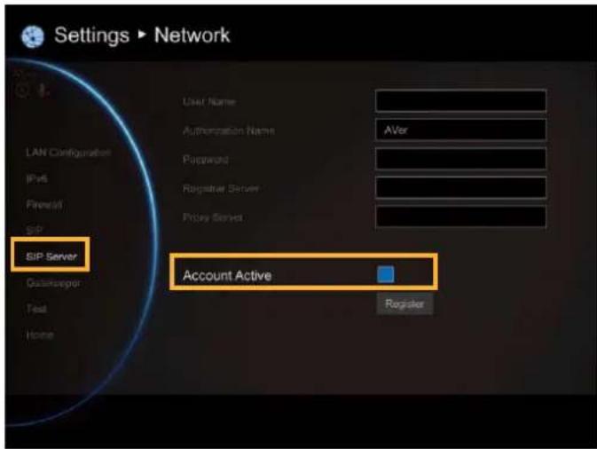
Account Active
Select Use Registrar check box and press to activate/deactivated using Registrar.

GATEKEEPER
The Gatekeeper in AVer EVC serves the purpose of translating services from E.164IDs to IP addresses in an H.323 network.
Select Network | Gatekeeper and press

Configure the following relative items to setup the Gatekeeper.
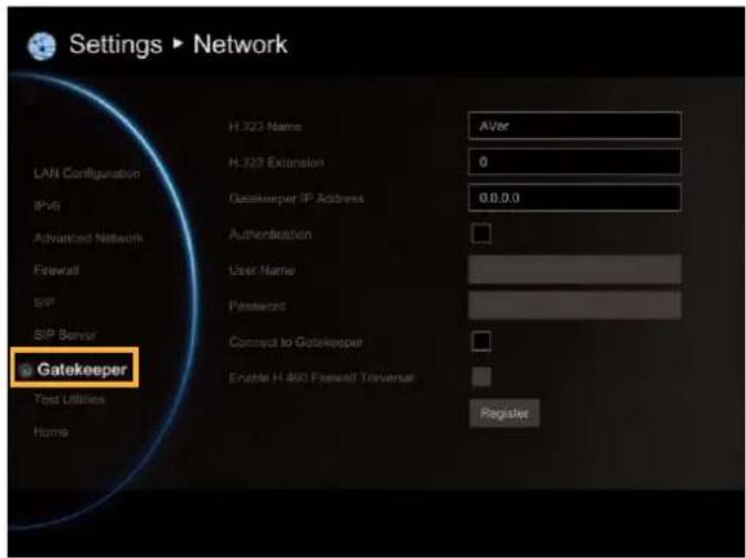
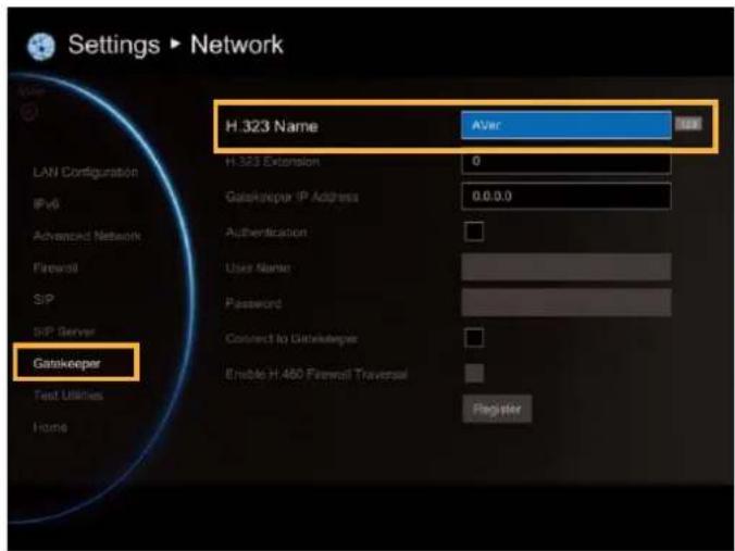
H.323 Name
Specify the name that gatekeepers and gateways can use to identify this system. Enter the name; the gatekeeper will use this name for identification.
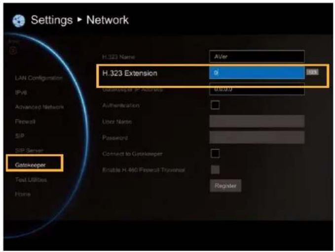
H.323 Extension
Enter a numeric value for the gatekeeper to identify your system further.
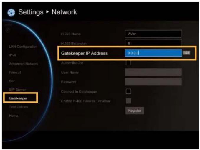
Gatekeeper IP Address
Enter the IP address for the gatekeeper server.
Authentication
Select the “Authentication” check box to activate gatekeeper authentication if gatekeeper requires authentication.
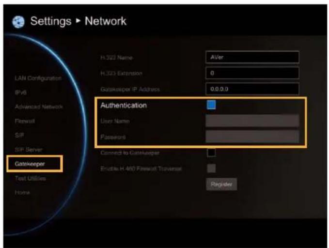
User Name and Password: Enter the user name and password for gatekeeper authorization.
Connect to Gatekeeper
Select this check box to Activate/deactivate gatekeeper.
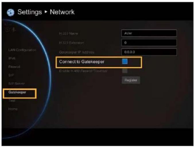
Make sure to setup the Gatekeeper before setting up the Firewall.
Enable H.460 Firewall Traversal
If you want to enable the H.460 Firewall Traversal, please set the following ports in port forwarding in your firewall before start installing your EVC.
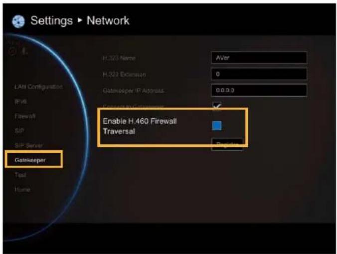
Make sure your gatekeeper supports H.460 Firewall Traversal before enabling it.
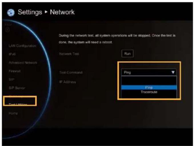
TEST UTILITIES
Network Test
This feature tests the network ability between local and far site.
Select Network | Test Utilities and press

Select Run to start testing.
Wait until it finishes the network test. The check mark will appear if the network test is successful. If it fails, save the report in a USB flash drive and contact our technical support.
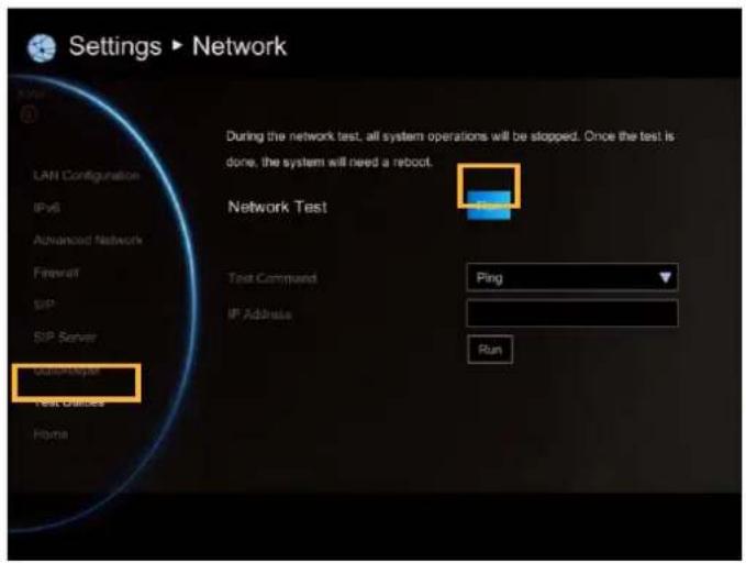
Test Command
To ping or traceroute the far site device.
Select Network | Test Utilities and press

Select Test Command and press

- Ping: Ping is used to test the reachability of a host on an Internet Protocol (IP) network, and to measure the round-trip time for messages sent from the originating host to a destination and echoed back to the source.
- Traceroute: traceroute is displayed the route (path) and measuring transit delays of packets across an Internet Protocol (IP) network.
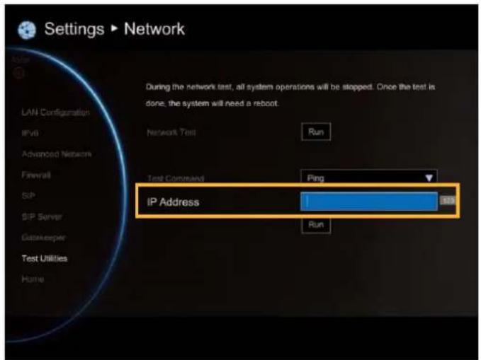
IP Address: Enter the IP address of device that user wants to ping or traceroute.
Finally, select Run to start ping or traceroute.
Web Configurations
You can use the internet browser to access your AVer EVC system through a LAN RJ-45 cable to setup a AVer EVC system remotely. You can also access the Phonebook to add, edit and delete entries, view and download the call history, update the system, and restore your previous settings. For web configurations, your AVer EVC system default IP address is: 192.168.0.1.
Please change your EVC's IP address at the start.
Using the WebTool
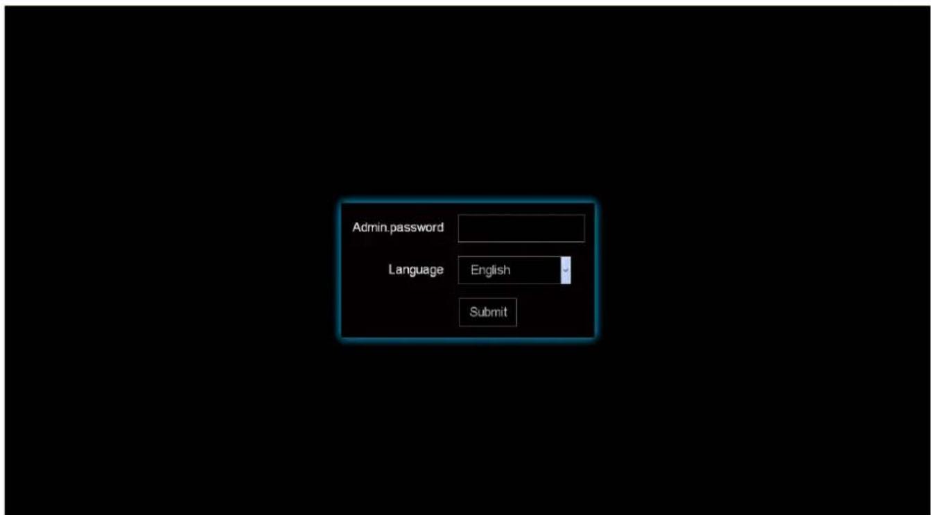
Enter your EVC's IP address in the URL field. Enable Web Admin setting must be activated and your will need to enter admin password to long in.
In Web Tool login screen, user can select the Language of Web Tool and enter the password, click Submit button to login.
Default password is 1234
After login, user should see the video screen of local site.

is indicated in background view mode.

dicated in live view mode.
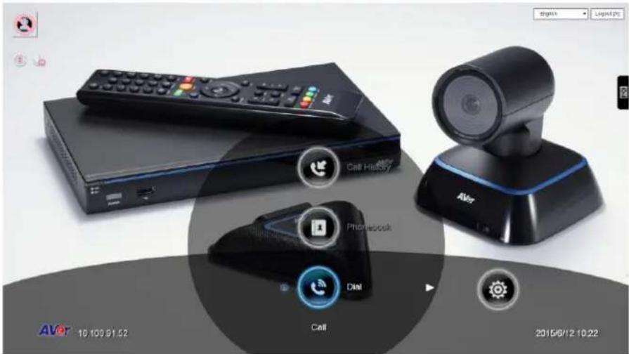
Click ☐ on can call out on-screen remote controller. You can use mouse to click the on-screen remote controller to operate functions on WebTool.
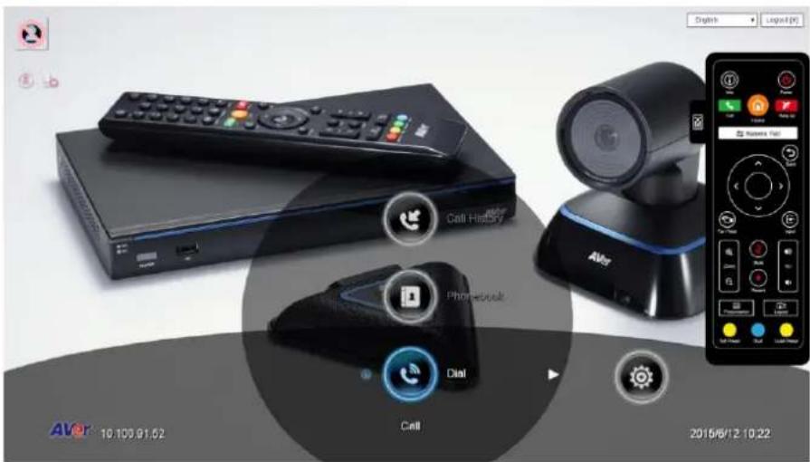
Click button can switch to numeric pad and phonebook button.
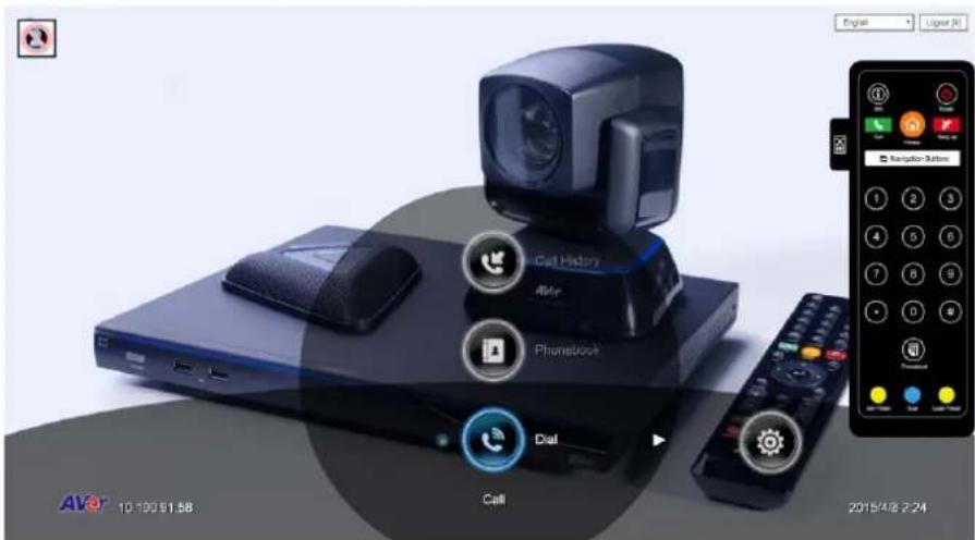
Click button can switch back to navigation buttons.
In the WebTool page, you can access the following:
- Phonebook
- Dial
- Call History
- Video/Audio
- General Setting
- Network
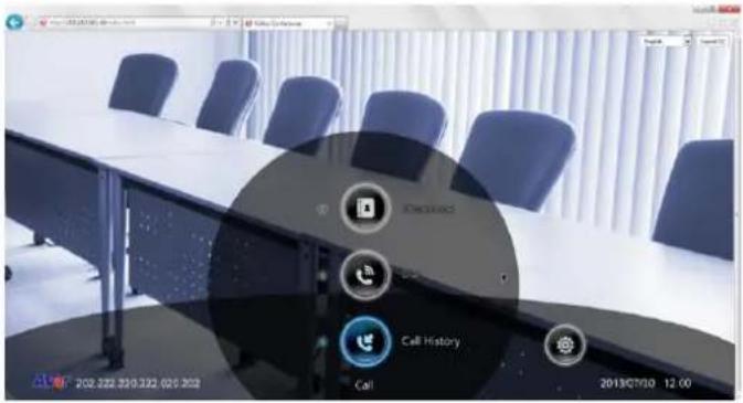
You can use the mouse to click the specified icon for a selection.
Managing Phonebook
In the Phonebook page of WebTool, all functions are the same as your AVer EVC Application. One different is the Upload/Download.
Edit and Save
-
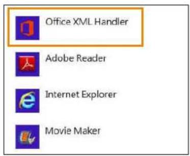
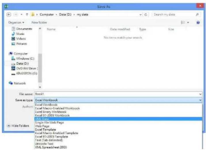
Locate and open the file using MS Excel and select Office XML Handler to create a schema based on the XML source data.
-
Edit the file.
-
Make sure to save the file as XML Data so it can be uploaded back to the system.
| A | B | C | D | E | |
| 1 | site | h323 | call_quality | group | sip |
| 2 | China | 10.100.91.49 | 256 | Branch office | |
| 3 | US | 512 | Branch office | 1234 | |
| 4 | SUPER | 192.168.0.1 | 64 | Customer | |
| 5 | Avte | 1024 | Customer | 10.100.93.68 | |
| 6 | Jack Lin | 192.168.0.8 | 64 | Customer | |
| 7 | Lucky | 768 | Customer | 10.100.93.67 |
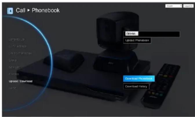
Download Phonebook Entries
Download allows you to download contact data from your AVer EVC system.
- Click Phonebook | Upload/Download.
- The saving Phonebook data from Aver EVC system dialogue box will appear,
- Click "Save" to save the file.
- After saving, you have to re-arrange your browser to update your WebTool Phonebook so that it can be the same as your EVC system.
Upload Phonebook Entries
Upload allows you to upload the data that you have edited or added from your WebTool to your AVer EVC system.
- Click Phonebook | Upload/Download
- Click "Upload Phonebook" to upload edited or added contents to your Aver EVC system directly.
- You can also click "Browser" to open the Phonebook file .xml saved in your PC to upload it to your Aver EVC system.
- After completing upload, the contents of Phonebook on your Aver EVC system will be modified in time.
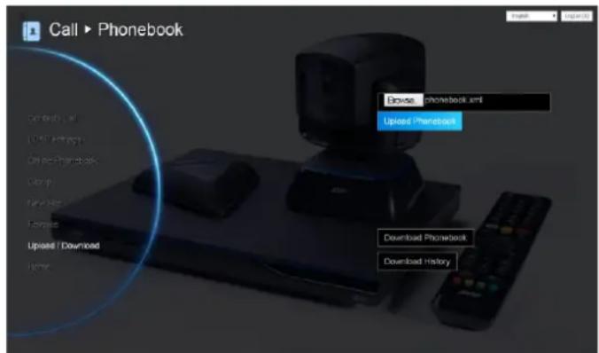
You can also download the phonebook entries and upload them to another AVer EVC unit.
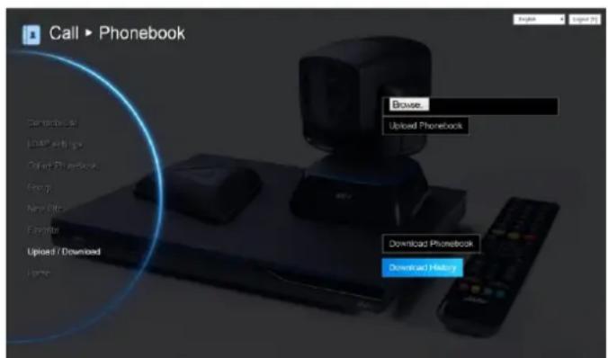
Download Call History Entries
Download History allows you to download call history list from your AVer EVC system.
- Click Phonebook | Upload/Download.
- Click "Download History" to download call history from to your AVer EVC system directly.
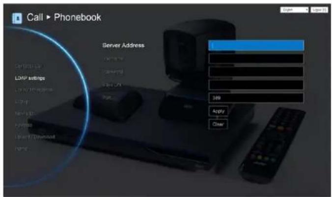
LDAP Setting
Setup your LDAP server then download your online phonebook.
- Click Phonebook | LDAP Setting
- Enter the following information:
■ Server Address: Enter LDAP server IP address.
■ Username: Enter username of LDAP server.
■ Password: Enter password of LDAP server.
■ Base DN: Enter LDAP object name / path. After entering username and password for authentication, it will start to search from LDAP Base DN name / path.
■ Port: The port for EVC and LDAP server to communicate. The default value is 389.
-
Click Apply to save the settings.
-
The download phonebook will be displayed in "Online Phonebook" section.
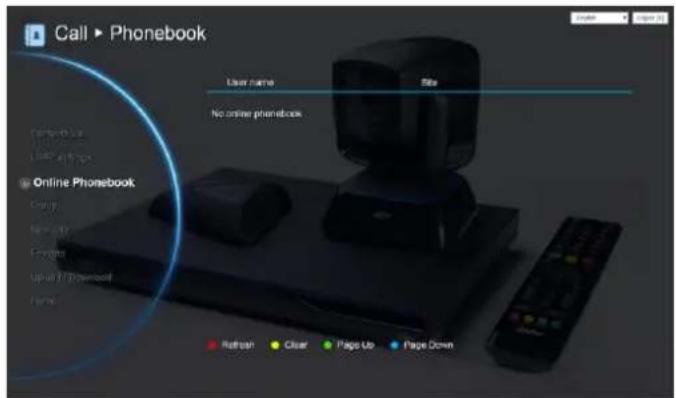
Online Phonebook
To view the phonebook is downloaded from LDAP server. You can make a call directly and save into contact list.
Click Phonebook | Online Phonebook.
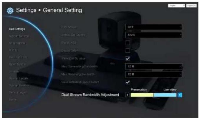
General Setting
DUAL STREAM BANDWIDTH ADJUSTMENT
Adjust bandwidth of presentation and live video.
- Click General Setting | Call Setting
- Click ◀ and ▶ to adjust the bandwidth.
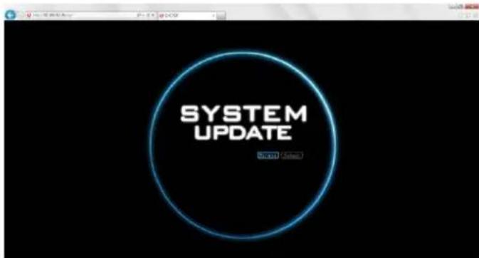
Update System
You can update the latest EVC firmware to your AVer EVC system from AVer EVC WebTool.
- Click General Setting | System Update
-
Click "System Update".
-
Click "Select" to browse and locate the downloaded firmware file .dat.
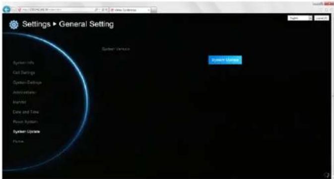
- Click "Submit" to begin the system update or Cancel to stop this operation.
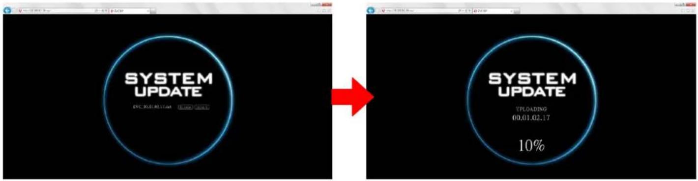
WARNING! Please do not perform any operations during the updating process.
EZ Join
Easy for joining a MCU bridge or cloud call.
In Dial screen, you has option to create few entries for most commonly used bridge/cloud call. Those entries are defined by a XML config file.
Please contact the AVer support team (http://www.aver.com/Technical-Support) to get the XML config file.
You can modify sample XML to fit their environment, upload it by Web Tool.
Maximum can upload 7 XML files.
![Settings ▶ General Setting English Logout [X] System Version 00.01.10.09/0021/0 Call Settings System Settings Administrator Monitor Date and Time Reset System System Update System Restore Default Layout Home System Update EZHJoin Browse... Upload](/content/2026/05/933999/images/99ee305d73ced82490a38c88358ed09a3e923b553176657a33d2ac62bd1a6e63.jpg)
Video/Audio
Primary Input source
The default of primary input source is "Camera". User can change the primary input source to "VGA".
- Click Video/Audio | Camera
- Select "Primary Input Source" and select the input source(Camera or VGA)
![Settings ▶ Video / Audio English Logout [X] White Balance Auto Exposure 5 Frequency Auto Sharpness Medium Primary Input Source Camera Camera Camera Upside-down VGA Enable Auto Focus Scene mode Standard](/content/2026/05/933999/images/c64668c0365415fdefeeb1ea222227153a1970437a109cd1f4f8ae2fecd180d1.jpg)
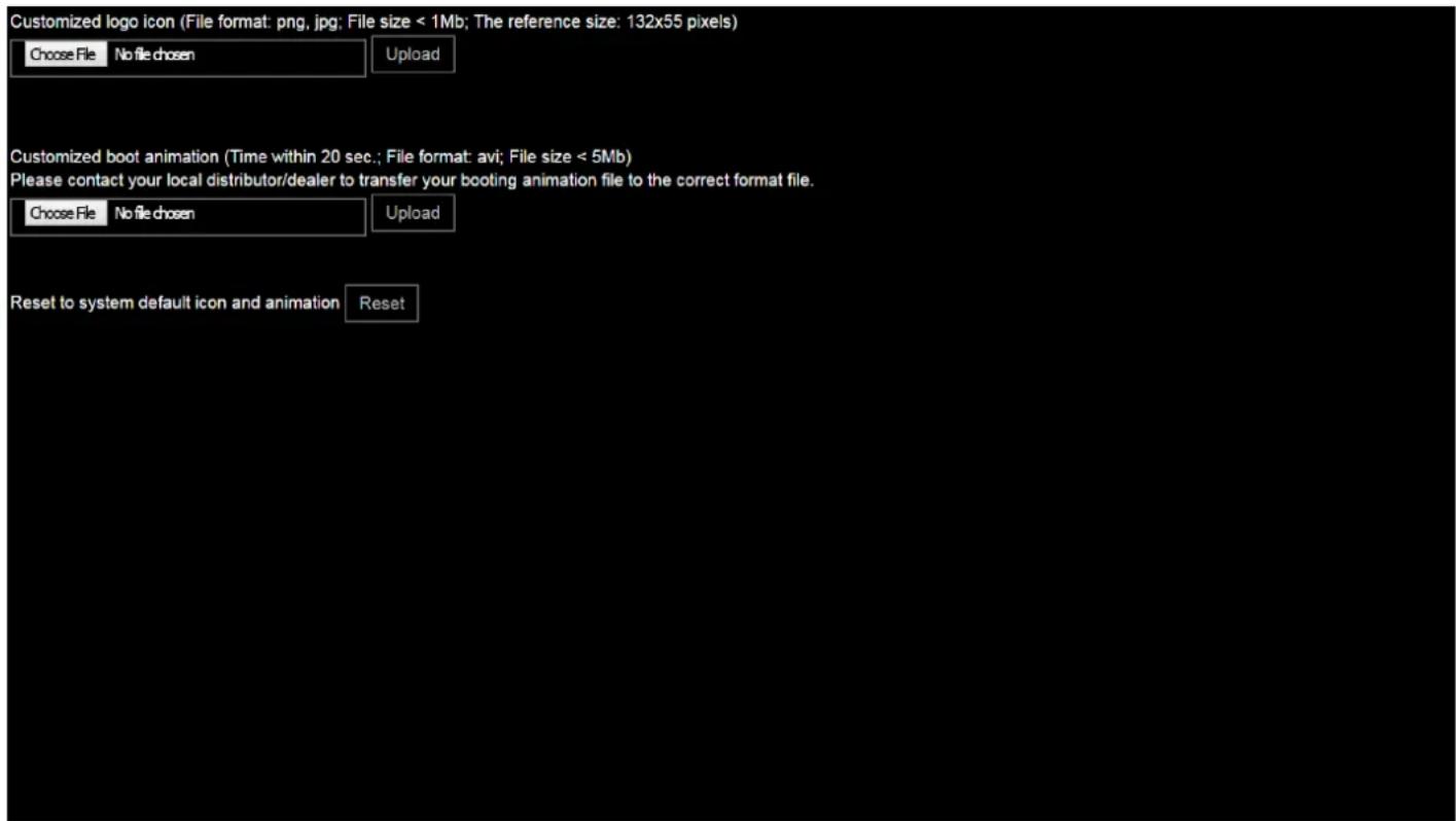
Customized Logo and Boot Animation
User can change logo icon and boot animation file.
- Please enter the following URL in your browser.
Http://EVC's IP address/admin/customization/logo-manage.html
- The customization screen will show.
-
Click "Upload" button and choose the logo/animation file. File for logo and animation are some limitations:
-
Logo file: file size is less or equal to 1MB and resolution is 132 x 55 pixels.
-
Animation file: file size is less or equal to 5MB, file format is *.avi, and file time is less or equal to 20 seconds. Please contact your local distributor/dealer to transfer your booting animation file to the correct format files.
-
If you want to use the default logo and animation file, click Reset button.
Public IP Configuration (Outside of Firewall)
Your EVC system is connecting directly to the internet.
natural_image
Product photo of a black remote control unit, a cable via keyboard, and a triangular remote device (no visible text or symbols)EVC


natural_image
Globe illustration showing continents with green and blue oceans (no text or labels)Internet
-
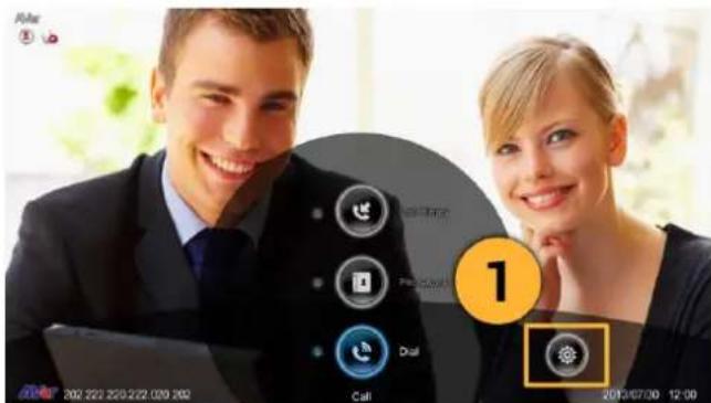
From the remote press "Home"->"->"Setting".
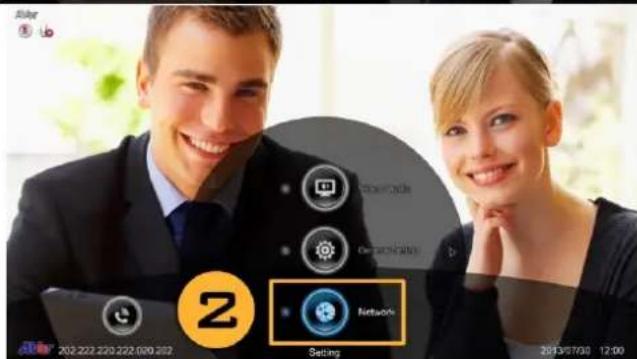
-
Press "▼" -> "Network".
-
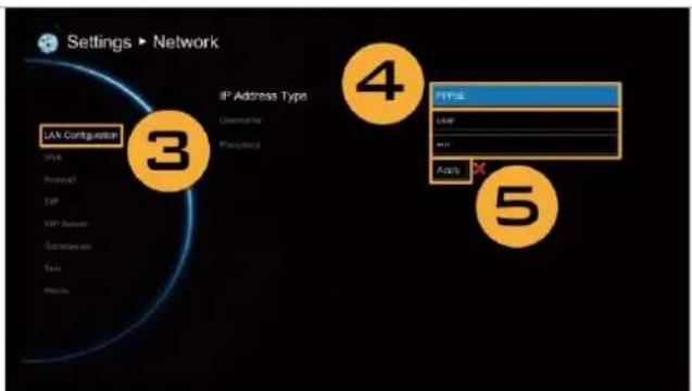
Press "LAN Configuration".
-
And In the drop-down list "Obtain IP address", choose "Static IP" or "PPPoE".
- Static IP: Input the "IP address", "Subnet Mask" and "Default Gateway".
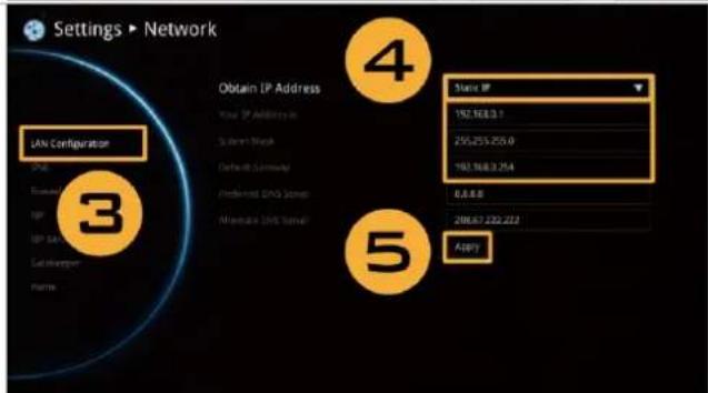
Static IP setting
- PPPoE: Input the PPPoE login "User name" and "Password".
-
Select "Apply" and press (inter).
-
Press "Home" on the remote to return to the home menu.
Press the (Call) button on the remote and you are ready to make your first call.
Private IP Configuration (Behind Firewall with Port Forwarding)
Please make sure you have set the following ports in port forwarding in your firewall.
| Port | Function | Type |
| 1719 | Gatekeeper | UDP |
| 1720 | H.323 Call setup | TCP |
| 30000~30019 | Signalling and control for audio, call, video and data/FECC | TCP and UDP |
| 80 | HTTP Interface (WebTool) | TCP |
| 23 | Telnet | TCP |
| 5060 | SIP | TCP and UDP |
| 5061 | TCP |
Your EVC system is connecting to the internet through a firewall.

-
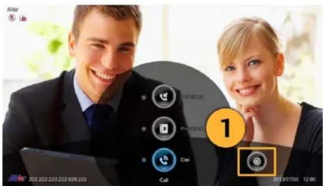
From the remote press "Home"->"->"Setting".
-
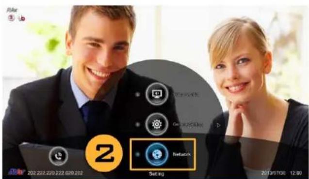
Press "▼" -> "Network".
-
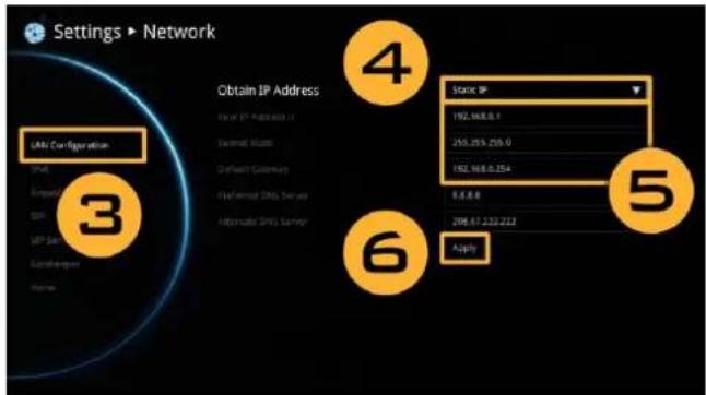
Press "LAN Configuration".
-
And In the drop-down list "Obtain IP address", choose "Static IP".
-
Manually input the "IP address", "Subnet Mask" and "Default Gateway".
-
Select "Apply" and press (Enter).
-
Press 📊(Back) on the remote to return to previous menu. (If you have H.323 ALG enabled, skip to step 10).
-
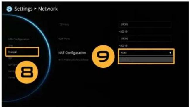
In the same page, go to "Firewall" and press (Enter).
-
Select "ON" in the NAT check box and enter the IP address in the "NAT Public (WAN) address" field.
-
Press the "Home" button on the remote to return the home menu.
-
Press the Call button on the remote and you are ready to make your first call.

H.460 Gatekeeper with Firewall Traversal
Your EVC system is connecting to the internet through a firewall and your have a Gatekeeper outside the firewall.
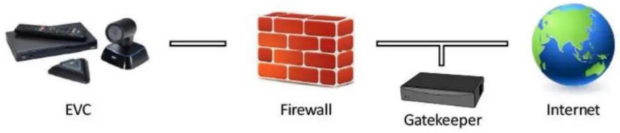
flowchart
graph LR
    A["EVC"] --> B["Firewall"]
    B --> C["Gatekeeper"]
    C --> D["Internet"]
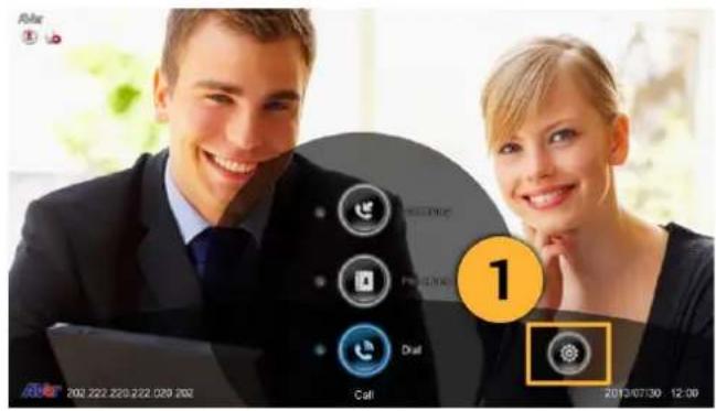
- From the remote press "Home" -> " > " -> "Setting".
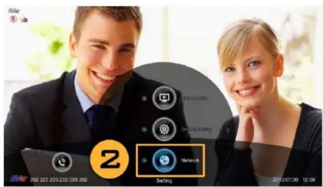
- Press "▼" -> "Network".
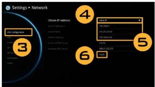
- Press "LAN Configuration (IPv4)".
- And In the drop-down list "Obtain IP address", choose "Static IP".
- Manually input the "IP address", "Subnet Mask" and "Default Gateway".
- Select "Apply" and press (inter).
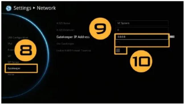
- In the same page, go to "Gatekeeper" and press (Enter).
- Enter the IP address of your Gatekeeper in the "Gatekeeper IP Address" field and enable the "Use Gatekeeper" check box.
- Enable the "Enable H.460 firewall Traversal" option.
- Press the "Home" button on the remote to return the home menu.
- Press the (Call) button on the remote and you are ready to make your first call.
Troubleshooting
Audio
-
Can't hear the audio during a call
-
Make sure the MICs are not muted.
- Make sure the MIC connections are properly connected as illustrated in the manual.
-
Ensure proper volume level on the system.
-
The audio quality is poor
-
Ensure the MIC is not damaged.
- Try to adjust the "Mic Gain Level".
- Make sure the MIC is not facing the output speakers to prevent echo.
Video/Display
-
Video conference call is established but no video or voice.
-
If you are connecting to Aver EVC with firewall, make sure you have done the port forwarding correctly. For non H.323 ALG firewall, please set the NAT configuration and the WAN IP address on Aver EVC system is entered.
- We suggest having a fixed public IP address for Aver EVC system. With Dynamic public IP address, it will change after a certain period which depends on your local ISP.
-
There is a routing issue if you installed two Aver EVC systems sharing one public IP address.
-
Unable to connect to other Video Conferencing systems.
-
Check to see if you dial the correct IP address.
- Ensure the power status of the device from the other sited is on.
- Verify if the firewall blocks the inbound traffics from the other site.
-
Verify if the other site rejected your Video Conferencing call.
-
Unable to see the OSD.
-
Check to see if your cable is connecting correctly.
- Make sure your system and display are well-connected and then reboot your system. (Your display should be switched on before you reboot your system.)
-
Press "Dual" button on remote controller (User needs to keep pressing until OSD menu is shown).
-
Why the content sharing is not 720p when the source is 720p?
- Aver EVC systems support up to 720p content sharing and default value is XGA. For a 16:9(720P) video display, you have to configure it by manually.
- Why can't I see the UI configuration screen after connecting the VGA cable and powering on Aver EVC systems upon screen saver mode?
- Please plug and unplug the VGA connector again to re-connection the VGA cable.
Network
- The LAN connection is fail.
- Make sure you have changed your default IP address. The default IP address is 192.168.0.1, in order not to conflict with other devices in the same LAN, please change your IP address at the start.
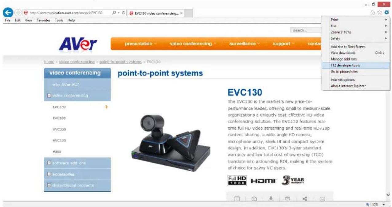
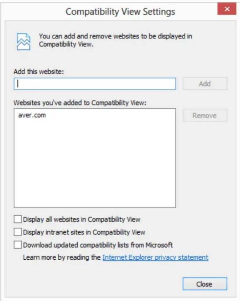
- Cannot open WebTool by IE9 and IE10.
- Click (General Setting icon) in IE.
- Select "F12 developer tools".
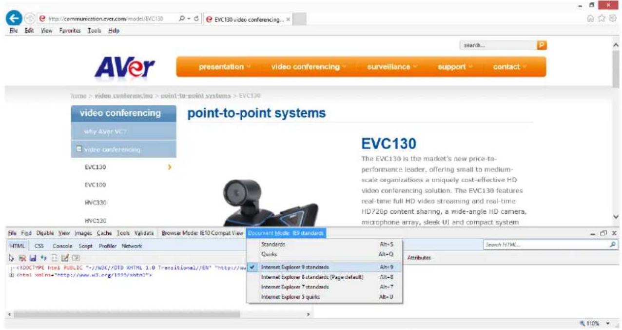
5. Change Document Mode to Internet Explorer 9 standards.
6. Disable intranet sites in Compatibility View. Go to "Tools | Compatibility view settings".
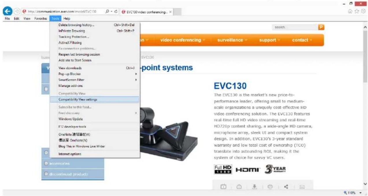
- Unclick the checkbox "Display intranet sites in Compatibility View" and then click "Close".
Others
-
Unable to connect the call and the "Call failed" error message appears on the screen.
-
Ensure the IP address for the calling is correctly.
- Ensure the other end of your calling does not set their system to “Do Not Disturb” mode or pick up the phone.
-
Ensure you are not calling to a system that has already up to maximum call-in limitation.
-
Forget the administrator password.
- Please contact Aver technical support for assistance.
-
Unable to control the far end camera.
-
Make sure the "Cam Ctrl" icon is positioned on the screen you want to control. Press "Far/Near" button on the remote controller to switch to the desired screen.
-
Make sure the far site has enabled the “Far Control of Near Camera” setting. To enable this function, press “Home” button and got to Setting | System setting and then select “Far control of Near Camera”.
-
Aver EVC cannot detect the USB device.
-
Unplug and plug the USB flash drive again and wait for 10 to 15 seconds for the system to re-detect the new USB device.
- We do not recommend using an external HDD; it may cause system errors or recording failures.
Remote Control Battery Safety Information
- Store batteries in any cool & dry place.
- Do not dispose used batteries in domestic waste. Dispose batteries at special collection points or return to stores if applies.
- Remove the batteries if they are not in use for long period of time. Battery leakage and corrosion can damage the remote control, dispose batteries safely.
- Do not mix and use old and new batteries.
- Do not mix and use different types of batteries: alkaline, standard (carbon -zinc) or rechargeable (nickel-cadmium).
- Do not dispose batteries in a fire.
- Do not attempt to short circuit the battery terminals.
Limited Warranty
For a period of time beginning on the date of purchase of the applicable product and extending as set forth in the Warranty Period of AVer Product Purchased section of the warranty card, AVer Information Inc. ("AVer") warrants that the applicable product ("Product") substantially conforms to AVer's documentation for the product and that its manufacture and components are free of defects in material and workmanship under normal use. "You" as used in this agreement means you individually or the business entity on whose behalf you use or install the product, as applicable. This limited warranty extends only to you as the original purchaser. Except for the foregoing, the Product is provided "AS IS." In no event does AVer warrant that You will be able to operate the Product without problems or interruptions, or that the Product is suitable you're your purposes. Your exclusive remedy and the entire liability of AVer under this paragraph shall be, at AVer's option, the repair or replacement of the Product with the same or a comparable product. This warranty does not apply to (a) any Product on which the serial number has been defaced, modified, or removed, or (b) cartons, cases, batteries, cabinets, tapes, or accessories used with this product. This warranty does not apply to any Product that has suffered damage, deterioration or malfunction due to (a) accident, abuse, misuse, neglect, fire, water, lightning, or other acts of nature, commercial or industrial use, unauthorized product modification or failure to follow instructions included with the Product, (b) misapplication of service by someone other than the manufacturer's representative, (c) any shipment damages (such claims must be made with the carrier), or (d) any other causes that do not relate to a Product defect. The Warranty Period of any repaired or replaced Product shall be the longer of (a) the original Warranty Period or (b) thirty (30) days from the date of delivery of the repaired or replaced product.
Limitations of Warranty
AVer makes no warranties to any third party. You are responsible for all claims, damages, settlements, expenses, and attorneys' fees with respect to claims made against you as a result of your use or misuse of the Product. This warranty applies only if the Product is installed, operated, maintained, and used in accordance with AVer specifications. Specifically, the warranties do not extend to any failure caused by (i) accident, unusual physical, electrical, or electromagnetic stress, neglect or misuse, (ii) fluctuations in electrical power beyond Aver specifications, (iii) use of the Product with any accessories or options not furnished by AVer or its authorized agents, or (iv) installation, alteration, or repair of the Product by anyone other than AVer or its authorized agents.
Disclaimer of Warranty
EXCEPT AS EXPRESSLY PROVIDED OTHERWISE HEREIN AND TO THE MAXIMUM EXTENT PERMITTED BY APPLICABLE LAW, AVER DISCLAIMS ALL OTHER WARRANTIES WITH RESPECT TO THE PRODUCT, WHETHER EXPRESS, IMPLIED, STATUTORY OR OTHERWISE, INCLUDING WITHOUT LIMITATION, SATISFACTORY QUALITY, COURSE OF DEALING, TRADE USAGE OR PRACTICE OR THE IMPLIED WARRANTIES OF MERCHANTABILITY, FITNESS FOR A PARTICULAR PURPOSE OR NONINFRINGEMENT OF THIRD PARTY RIGHTS.
Limitation of Liability
IN NO EVENT SHALL AVER BE LIABLE FOR INDIRECT, INCIDENTAL, SPECIAL, EXEMPLARY, PUNITIVE, OR CONSEQUENTIAL DAMAGES OF ANY NATURE INCLUDING, BUT NOT LIMITED TO, LOSS OF PROFITS, DATA, REVENUE, PRODUCTION, OR USE, BUSINESS INTERRUPTION, OR PROCUREMENT OF SUBSTITUTE GOODS OR SERVICES ARISING OUT OF OR IN CONNECTION WITH THIS LIMITED WARRANTY, OR THE USE OR PERFORMANCE OF ANY PRODUCT, WHETHER BASED ON CONTRACT OR TORT, INCLUDING NEGLIGENCE, OR ANY OTHER LEGAL THEORY, EVEN IF AVER HAS ADVISED OF THE POSSIBILITY OF SUCH DAMAGES. AVER'S TOTAL, AGGREGATE LIABILITY FOR DAMAGES OF ANY NATURE, REGARDLESS OF FORM OF ACTION, SHALL IN NO EVENT EXCEED THE AMOUNT PAID BY YOU TO AVER FOR THE SPECIFIC PRODUCT UPON WHICH LIABILITY IS BASED.
Governing Law and Your Rights
This warranty gives you specific legal rights; you may also have other rights granted under state law. These rights vary from state to state.
Federal Communications Commission Statement (Class A)
FCC NOTE- This equipment has been tested and found to comply with the limits for a Class A digital device, pursuant to Part 15 of the FCC Rules. These limits are designed to provide reasonable protection against harmful interference in a residential installation. This equipment generates uses and can radiate radio frequency energy and, if not installed and used in accordance with the instructions, may cause harmful interference to radio communications. However, there is no guarantee that interference will not occur in a particular installation. If this equipment does cause harmful interference to radio or television reception, which can be determined by tuning the equipment off and on, the user is encouraged to try to correct the interference by one or more of the following measures:
Reorient or relocate the receiving antenna.
Increase the separation between the equipment and receiver.
Connect the equipment into an outlet on a circuit different from that to which the receiver is connected.
Consult the dealer or an experienced radio/television technician for help.
For warranty period, please refer to the warranty card.
Class A ITE
Class A ITE is a category of all other ITE which satisfies the class A ITE limits but not the class B ITE limits. Such equipment should not be restricted in its sale but the following warning shall be included in the instructions for use:
Warning - This is a class A product. In a domestic environment this product may cause radio interference in which case the user may be required to take adequate measures.
CE Class A (EMC)
CE This product is herewith confirmed to comply with the requirements set out in the Council
Directives on the Approximation of the laws of the Member States relating to Electromagnetic Compatibility Directive 2004/108/EC.
Warning - This is a Class A product. In a domestic environment this product may cause radio interference in which case the user may be required to take adequate measures to correct this interference.
Copyright
© 2016 by AVer Information Inc. All rights reserved. No part of this publication may be reproduced, transmitted, transcribed, stored in a retrieval system, or translated into any language in any form by any means without the written permission of AVer INFORMATION Inc.
The mark of Crossed-out wheeled bin indicates that this product must not be disposed of with your other household waste. Instead, you need to dispose of the waste equipment by handing it over to a designated collection point for the recycling of waste electrical and electronic equipment. For more information about where to drop off your waste equipment for recycling, please contact your household waste disposal service or the shop where you purchased the product.
Trademarks
AVer is registered trademarks of AVer Information Inc. Other trademarks used herein for description purpose only belong to each of their companies.
Disclaimer
No warranty or representation, either expressed or implied, is made with respect to the contents of this documentation, its quality, performance, merchantability, or fitness for a particular purpose. Information presented in this documentation has been carefully checked for reliability; however, no responsibility is assumed for inaccuracies. The information contained in this documentation is subject to change without notice. In no event will AVer be liable for direct, indirect, special, incidental, or consequential damages arising out of the use or inability to use this product or documentation, even if advised of the possibility of such damages.
AVer Information Inc.
Website: http://www.aver.com
- CONTENTS
- INTRODUCTION .... 1
- INSTALLATION .... 3
- BEFORE INSTALLATION....14
- AVER EVC WIZARD SETUP 16
- AVER EVC OPERATION....24
- WEB CONFIGURATIONS 82
- SCENARIOS FOR LAN CONNECTION....91
- TROUBLESHOOTING 96
- REMOTE CONTROL BATTERY SAFETY INFORMATION......100
- LIMITED WARRANTY 101
- FEDERAL COMMUNICATIONS COMMISSION STATEMENT (CLASS A)....102
- COPYRIGHT 103
- Introduction
- Features
- Package Contents
- Getting Familiar With the AVer EVC -Series
- MAIN SYSTEM
- MIC
- REMOTE CONTROLLER
- Connections
- CONNECTING MONITORS (VGA OUT/HDMI OUT)
- CONNECTING THE CAMERA (CAMERA IN)
- CONNECTING THE MIC (MIC IN)
- CONNECTING THE LAN (RJ-45)
- CONNECTING THE POWER (DC 12V)
- CONNECTING PC (VGA IN)
- CONNECTING THE AUDIO (AUDIO IN/OUT)
- AUDIO IN:
- AUDIO OUT:
- USB STORAGE (USB PORTS)
- Before Installation
- Using the Camera
- Infrared Sensor (IR)
- Positioning the MIC
- START
- LANGUAGE
- Select the language of the EVC system.
- SITE NAME
- [Note]
- NETWORK SETTING
- Select the network environment that user has used.
- Obtain Address is
- SIP SETTING
- DATE AND TIME SETTING
- NETWORK TIME PROTOCOL (NTP)
- MANUALLY SETTING
- Aver EVC OPERATION
- Before You Begin
- Home Screen
- CAMERA AND MIC ICONS
- WAN ADDRESS
- REAL-TIME CLOCK
- SYSTEM INFO
- Dial
- Call to
- Call Type
- Call Quality
- Phonebook
- GROUP
- Search a Created Group
- Edit Group
- NEW SITE (CONTACT IN PHONEBOOK)
- Edit New Site
- Delete New Site
- CONTACTS LIST
- FAVORITE
- ONLINE PHONEBOOK
- Call History
- Select Call History and press
- General Setting
- CALL SETTINGS
- Default Call Quality
- Enable/Disable AES
- Enable/Disable QoS
- Show Call Duration
- Max. Transmitting/Receiving Bandwidth
- SYSTEM SETTINGS
- ADMINISTRATOR
- Enable VCLine/ScreenShare
- Change VCLine/ScreenShare Password
- Save System Log
- Firmware Update Notice
- Far End Camera Control
- Wake-On-LAN (WOL)
- MONITOR
- TV Underscan
- DATE AND TIME
- Enable NTP
- NTP Server
- Timezone
- Year and Hour
- RESET SYSTEM
- DEFAULT LAYOUT
- Video/Audio
- CAMERA
- Select Video/Audio | Camera and press
- Exposure
- Frequency
- Sharpness
- Camera Upside-down
- MICROPHONE
- Broadcast Support(HDMI)
- VIDEO/AUDIO CODECS
- Network
- LAN CONFIGURATION
- IP Address Type
- Your IP address is
- Subnet Mask
- Default Gateway
- Preferred/Alternate DNS Server
- LAN CONFIGURATION (IPV6)
- Prefix Length
- ADVANCE NETWORK
- EAP 802.1x
- VLAN
- FIREWALL
- TCP/UDP Ports
- Enable UPnP
- NAT Configuration
- NAT Public (WAN) Address
- SIP
- SIP Site Name
- Internet Protocol
- SIP Transport Protocol
- SIP Port
- Enable SIP
- BFCP
- Enable SRTP
- STUN Server
- STUN Port
- Enable STUN Server
- SIP SERVER
- Authorization Name
- Password
- Registrar Server
- Proxy Server
- Account Active
- GATEKEEPER
- H.323 Name
- H.323 Extension
- Gatekeeper IP Address
- Authentication
- Connect to Gatekeeper
- Enable H.460 Firewall Traversal
- TEST UTILITIES
- Web Configurations
- Using the WebTool
- Managing Phonebook
- Edit and Save
- Download Phonebook Entries
- Upload Phonebook Entries
- Download Call History Entries
- LDAP Setting
- DUAL STREAM BANDWIDTH ADJUSTMENT
- Update System
- EZ Join
- Primary Input source
- Customized Logo and Boot Animation
- Public IP Configuration (Outside of Firewall)
- Private IP Configuration (Behind Firewall with Port Forwarding)
- H.460 Gatekeeper with Firewall Traversal
- Troubleshooting
- Audio
- Video/Display
- Change Document Mode to Internet Explorer 9 standards.
- Disable intranet sites in Compatibility View. Go to "Tools | Compatibility view settings".
- Others
- Remote Control Battery Safety Information
- Limited Warranty
- Limitations of Warranty
- Disclaimer of Warranty
- Limitation of Liability
- Governing Law and Your Rights
- Federal Communications Commission Statement (Class A)
- Class A ITE
- CE Class A (EMC)
- Copyright
- Trademarks
- Disclaimer
Brand : AVer
Model : EVC130P
Category : Video Conferencing System