WeldSkill 155 - Welding machine Cigweld - Free user manual and instructions
Find the device manual for free WeldSkill 155 Cigweld in PDF.


| Product Type | Multi-process welding inverter (MIG, Stick, Lift TIG) |
| Brand | Cigweld |
| Model | WeldSkill 155 |
| Dimensions (H x W x D) | 371 mm x 205 mm x 478 mm |
| Weight | 13.7 kg |
| Power Supply | 240V AC ±15%, 50/60 Hz, single phase, 10A effective input current, 35A max input current |
| Welding Current Range (MIG) | 30 - 155 A |
| Duty Cycle (MIG at 40°C, 10 min) | 155 A @15%, 85 A @60%, 66 A @100% |
| Duty Cycle (Stick at 40°C, 10 min) | 135 A @15%, 67 A @60%, 52 A @100% |
| Duty Cycle (TIG at 40°C, 10 min) | 135 A @25%, 86 A @60%, 67 A @100% |
| Open Circuit Voltage (VRD On, Stick) | < 35 V DC |
| Protection Class | IP21S |
| Key Features | Digital voltage and amperage meters, VRD (voltage reduction device) for Stick mode, hot start, anti-stick, arc control (inductance) for MIG, wire feed unit with dual-groove feed rolls, burnback control, over-temperature protection, fan cooling, Euro MIG torch adaptor |
| Included Accessories | E-180 MIG torch (3 m, Euro), electrode holder lead (3 m), work clamp lead (3 m), Cutskill argon regulator/flowmeter, operating manual |
| Spare Parts Available | Yes, key spare parts include PCBA power inverter (W7006865), PCBA front panel (W7006866), fan assembly (W7006867), wire drive assembly (W7006868), gas solenoid valve (W7006869), spool hub assembly (W7006870), and more |
| Maintenance | Regularly clean interior (do not use compressed air), clean feed rolls, inspect cables and connections, check for loose parts, and have qualified electrician perform periodic inspections |
| Safety Features | VRD, over-temperature self-resetting thermostat, IP21S protection, safety instructions in manual, compliance with AS 60974.1 and IEC 60974.1 |
| Warranty | 2 years on power source, 3 months on accessories, 1 year on regulator/flowmeter (except consumables) |
Frequently Asked Questions - WeldSkill 155 Cigweld
User questions about WeldSkill 155 Cigweld
0 question about this device. Answer the ones you know or ask your own.
Ask a new question about this device
Download the instructions for your Welding machine in PDF format for free! Find your manual WeldSkill 155 - Cigweld and take your electronic device back in hand. On this page are published all the documents necessary for the use of your device. WeldSkill 155 by Cigweld.
USER MANUAL WeldSkill 155 Cigweld
WE APPRECIATE YOUR BUSINESS!
Congratulations on your new CIGWELD product. We are proud to have you as our customer and will strive to provide you with the best service and reliability in the industry. This product is backed by our extensive warranty and world-wide service network.
This Operating Manual has been designed to instruct you on the correct use and operation of your CIGWELD product. Your satisfaction with this product and its safe operation is our ultimate concern. Therefore please take the time to read the entire manual, especially the Safety Precautions. They will help you to avoid potential hazards that may exist when working with this product.
We have made every effort to provide you with accurate instructions, drawings, and photographs of the product(s) while writing this manual. However errors do occur and we apologize if there are any contained in this manual.
Due to our constant effort to bring you the best products, we may make an improvement that does not get reflected in the manual. If you are ever in doubt about what you see or read in this manual with the product you received, then check for a newer version of the manual on our website or contact our customer support for assistance.
YOU ARE IN GOOD COMPANY!
The Brand of Choice for Contractors and Fabricators Worldwide.
CIGWELD is a Market Leading Brand of Arc Welding Products for ESAB. We are a mainline supplier to major welding industry sectors in the Asia Pacific and emerging global markets including; Manufacturing, Construction, Mining, Automotive, Engineering, Rural and DIY.
We distinguish ourselves from our competition through market-leading, dependable products that have stood the test of time. We pride ourselves on technical innovation, competitive prices, excellent delivery, superior customer service and technical support, together with excellence in sales and marketing expertise.
Above all, we are committed to develop technologically advanced products to achieve a safer working environment for industry operators.
WARNING
Read and understand this entire Manual and your employer's safety practices before installing, operating, or servicing the equipment.
While the information contained in this Manual represents the Manufacturer's best judgement, the Manufacturer assumes no liability for its use.
CIGWELD WeldSkill 155 and 185 Welding Inverters
Instruction Manual Number 0-5492 for:
Part Numbers W1008155 and W1008185
Published by:
CIGWELD Pty Ltd
CIGWELD An ESAB Brand
71 Gower Street,
Preston, Victoria, Australia, 3072
+61 3 9474 7400 +61 3 9474 7391
www.cigweld.com.au
Copyright 2017
CIGWELD Pty Ltd
All rights reserved.
Reproduction of this work, in whole or in part, without written permission of the publisher is prohibited.
The publisher does not assume and hereby disclaims any liability to any party for any loss or damage caused by any error or omission in this Manual, whether such error results from negligence, accident, or any other cause.
For Printing Material Specification refer to document 47x1915.
Publication Date: 17-08-2017
Revision Date: 07-09-2017
Record the following information for Warranty purposes:
Where Purchased: ____
Purchase Date: ____
Equipment Serial #: ____
Be sure this information reaches the operator. You can get extra copies through your supplier.
CAUTION
These INSTRUCTIONS are for experienced operators. If you are not fully familiar with the principles of operation and safe practices for arc welding and cutting equipment, we urge you to read our booklet, “Precautions and Safe Practices for Arc Welding, Cutting, and Gouging,” Booklet 0-5407. Do NOT permit untrained persons to install, operate, or maintain this equipment. Do NOT attempt to install or operate this equipment until you have read and fully understand these instructions. If you do not fully understand these instructions, contact your supplier for further information. Be sure to read the Safety Precautions before installing or operating this equipment.
USER RESPONSIBILITY
This equipment will perform in conformity with the description thereof contained in this manual and accompanying labels and/or inserts when installed, operated, maintained and repaired in accordance with the instructions provided. This equipment must be checked periodically. Malfunctioning or poorly maintained equipment should not be used. Parts that are broken, missing, worn, distorted or contaminated should be replaced immediately. Should such repair or replacement become necessary, the manufacturer recommends that a telephone or written request for service advice be made to the Authorized Distributor from whom it was purchased.
This equipment or any of its parts should not be altered without the prior written approval of the manufacturer. The user of this equipment shall have the sole responsibility for any malfunction which results from improper use, faulty maintenance, damage, improper repair or alteration by anyone other than the manufacturer or a service facility designated by the manufacturer.
READ AND UNDERSTAND THE INSTRUCTION MANUAL BEFORE INSTALLING OR OPERATING. PROTECT YOURSELF AND OTHERS!
DECLARATION OF CONFORMITY
According to
The Arc Welding Power Source Directive AS 60974.1-2006 (equivalent to IEC 60974-1 Ed. 2.1)
The EMC Directive IEC 60974-10:2014 published on 06 February 2014
Type of equipment
Welding Inverter Power Source
Type designation etc.
Welding Performance
Brand name or trade mark
Cigweld
Manufacturer or his authorised representative established within the EEA
Name, address, telephone No:
Cigweld Pty Ltd
71 Gower Street
Preston, Victoria, Australia, 3072
Phone: +61 3 9474 7400
The following harmonised standard in force within the EEA has been used in the design:
AS 60974.1-2006, Arc Welding Equipment - Welding Power Sources (IEC 60974-1:2000, MOD)
IEC 60974-10-2014, Arc Welding Equipment - Part 10: Electromagnetic Compatibility (EMC) Requirements
AS 1674.2-2007, Safety in Welding and Allied Processes
Additional Information: Restrictive use, Class A equipment, intended for use in location other than resid
By signing this document, the undersigned declares as manufacturer, or the manufacturer's authorised representative established within the EEA, that the equipment in question complies with the safety requirements stated above.
Date Signature Position
25-07-2017
Ken Konopa Global Welding
Vice President,

2017
TABLE OF CONTENTS
SECTION 1:
ARC WELDING SAFETY INSTRUCTIONS AND WARNINGS....1-1
1.01 Arc Welding Hazards.... 1-1
1.02 PRINCIPAL SAFETY STANDARDS.... 1-5
SECTION 2:
INTRODUCTION 2-1
2.01 How To Use This Manual 2-1
2.02 Equipment Identification 2-1
2.03 Receipt Of Equipment 2-1
2.04 Symbol Chart.... 2-2
2.05 Description 2-3
2.06 User Responsibility.... 2-3
2.07 Packaged Item 2-3
2.08 Transporting Methods.... 2-3
2.09 Duty Cycle.... 2-4
2.10 Specifications 2-4
2.11 Optional Accessories 2-6
SECTION 3:
INSTALLATION 3-1
3.01 Environment 3-1
3.02 Location 3-1
3.03 Ventilation 3-1
3.04 Mains Supply Voltage Requirements 3-1
3.05 Generators 3-1
3.06 Extension Leads.... 3-1
3.07 Electromagnetic Compatibility 3-2
SECTION 4:
OPERATION 4-1
4.01 Overview 4-1
4.02 Power Source Controls, Indicators and Features 4-1
SECTION 5:
MIG (GMAW) WELDING 5-1
5.01 Shielding Gas Regulator/Flowmeter Operating Instructions.... 5-1
5.02 Attaching the MIG Torch (Euro) 5-3
5.03 Installing Minispool (100mm diameter) 5-4
5.04 Installing Handispool (200mm diameter) 5-5
5.05 Inserting Wire into the Wire Feed Mechanism 5-6
5.06 Feed Roller Pressure Adjustment.... 5-7
5.07 Changing the Feed Roll 5-7
5.08 Wire Reel Brake 5-8
5.09 Setup for MIG (GMAW) Welding with Gas Shielded Mig Wire 5-8
5.10 Setup for MIG (GMAW) Welding with Gasless MIG Wire (Flux Cored) ..... 5-10
5.11 Setup for SPOOL GUN MIG (GMAW) Welding with Gas Shielded Mig Wire (WeldSkill 185 Only)....5-11
5.12 MIG (GMAW/FCAW) Basic Welding Technique 5-12
5.13 CIGWELD MIG Wire Selection Chart.... 5-17
5.14 MIG (GMAW/FCAW) Welding Troubleshooting 5-18
TABLE OF CONTENTS
SECTION 6:
STICK (MMAW) WELDING 6-1
6.01 Setup For STICK (MMAW) Welding 6-1
6.02 Arc Welding Electrodes 6-2
6.03 Types of Electrodes.... 6-2
6.04 Size of Electrode 6-3
6.05 Storage of Electrodes.... 6-3
6.06 Electrode Polarity....6-3
6.07 Effects of Arc Welding Various Materials 6-4
6.08 Arc Welding Practice.... 6-4
6.09 Welding Position....6-4
6.10 Joint Preparations.... 6-5
6.11 Arc Welding Technique 6-6
6.12 The Welder.... 6-6
6.13 Striking the Arc 6-6
6.14 Arc Length 6-6
6.15 Rate of Travel 6-6
6.16 Making Welded Joints.... 6-6
6.17 Distortion....6-9
6.18 The Cause of Distortion 6-9
6.19 Overcoming Distortion Effects 6-9
6.20 Welding Problems 6-11
SECTION 7:
TIG (GTAW) WELDING....7-1
7.01 Shielding Gas Regulator/Flowmeter Operating Instructions.... 7-1
7.02 Setup For Lift TIG (GTAW) Welding 7-3
7.03 TIG (GTAW) Basic Welding Technique 7-5
7.04 TIG (GTAW) Welding Problems.... 7-7
SECTION 8:
ROUTINE SERVICE REQUIREMENTS AND POWER SOURCE PROBLEMS 8-1
8.01 Routine Maintenance & Inspection 8-1
8.02 Cleaning the Welding Power Source 8-1
8.03 Cleaning the Feed Rolls.... 8-1
8.04 Basic Troubleshooting 8-1
8.05 Welding Power Source Problems 8-2
SECTION 9: KEY SPARE PARTS ...... 9-1
9.01 WeldSkill 155 Key Spare Parts....9-1
9.02 WeldSkill 185 Key Spare Parts....9-2
9.03 E-180 MIG Torch 3m (P/N W4018800) Key Spare Parts....9-3
APPENDIX 1: WELDSKILL 155 CIRCUIT DIAGRAM ...... A-1
APPENDIX 2: WELDSKILL 185 CIRCUIT DIAGRAM ...... A-2
CIGWELD - LIMITED WARRANTY TERMS
WARRANTY SCHEDULE – WELDSKILL 155 & 185 INVERTERS
This Page Intentionally Blank
SECTION 1:
ARC WELDING SAFETY INSTRUCTIONS AND WARNINGS
WARNING
PROTECT YOURSELF AND OTHERS FROM POSSIBLE SERIOUS INJURY OR DEATH. KEEP CHILDREN AWAY. PACE-MAKER WEARERS KEEP AWAY UNTIL CONSULTING YOUR DOCTOR. DO NOT LOSE THESE INSTRUCTIONS. READ OPERATING/INSTRUCTION MANUAL BEFORE INSTALLING, OPERATING OR SERVICING THIS EQUIPMENT.
Welding products and welding processes can cause serious injury or death, or damage to other equipment or property, if the operator does not strictly observe all safety rules and take precautionary actions.
Safe practices have developed from past experience in the use of welding and cutting. These practices must be learned through study and training before using this equipment. Some of these practices apply to equipment connected to power lines; other practices apply to engine driven equipment. Anyone not having extensive training in welding and cutting practices should not attempt to weld.
Safe practices are outlined in the Australian Standard AS1674.2-2007 entitled: Safety in welding and allied processes Part 2: Electrical. This publication and other guides to what you should learn before operating this equipment are listed at the end of these safety precautions. HAVE ALL INSTALLATION, OPERATION, MAINTENANCE, AND REPAIR WORK PERFORMED ONLY BY QUALIFIED PEOPLE.
1.01 Arc Welding Hazards

WARNING
ELECTRIC SHOCK can kill.
Touching live electrical parts can cause fatal shocks or severe burns. The electrode and work circuit is electrically live whenever the output is on. The input power circuit and machine internal circuits are also live when power is on. In semiautomatic or automatic wire welding, the wire, wire reel, drive roll housing, and all metal parts touching the welding wire are electrically live. Incorrectly installed or improperly grounded equipment is a hazard.
- Do not touch live electrical parts.
- Wear dry, hole-free insulating gloves and body protection.
- Insulate yourself from work and ground using dry insulating mats or covers.
- Disconnect input power or stop engine before installing or servicing this equipment. Lock input power disconnect switch open, or remove line fuses so power cannot be turned on accidentally.
-
Properly install and ground this equipment according to its Owner's Manual and national, state, and local codes.
-
Turn off all equipment when not in use. Disconnect power to equipment if it will be left unattended or out of service.
- Use fully insulated electrode holders. Never dip holder in water to cool it or lay it down on the ground or the work surface. Do not touch holders connected to two welding machines at the same time or touch other people with the holder or electrode.
- Do not use worn, damaged, undersized, or poorly spliced cables.
- Do not wrap cables around your body.
- Ground the workpiece to a good electrical (earth) ground.
- Do not touch electrode while in contact with the work (ground) circuit.
- Use only well-maintained equipment. Repair or replace damaged parts at once.
- In confined spaces or damp locations, do not use a welder with AC output unless it is equipped with a voltage reducer. Use equipment with DC output.
- Wear a safety harness to prevent falling if working above floor level.
- Keep all panels and covers securely in place.
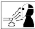
WARNING
ARC RAYS can burn eyes and skin; NOISE can damage hearing.
Arc rays from the welding process produce intense heat and strong ultraviolet rays that can burn eyes and skin. Noise from some processes can damage hearing.
-
Use a Welding Helmet or Welding Faceshield fitted with a proper shade of filter (see ANSI Z49.1 and AS 1674 listed in Safety Standards) to protect your face and eyes when welding or watching.
-
Wear approved safety glasses. Side shields recommended.
- Use protective screens or barriers to protect others from flash and glare; warn others not to watch the arc.
- Wear protective clothing made from durable, flame-resistant material (wool and leather) and foot protection.
- Use approved ear plugs or ear muffs if noise level is high.
- Never wear contact lenses while welding.
| Recommended Protective Filters for Electric Welding | ||
| Description of Process | Approximate Range of Welding Current in Amps | Minimum Shade Number of Filter(s) |
| Manual Metal Arc Welding - covered electrodes (MMAW) | Less than or equal to 100 8 | |
| 100 to 200 10 | ||
| 200 to 300 11 | ||
| 300 to 400 12 | ||
| Greater than 400 13 | ||
| Gas Metal Arc Welding (GWAW) (MIG) other than Aluminium and Stainless Steel | Less than or equal to 150 10 | |
| 150 to 250 11 | ||
| 250 to 300 12 | ||
| 300 to 400 13 | ||
| Greater than 400 14 | ||
| Gas Metal Arc Welding (GMAW) (MIG) Aluminium and Stainless Steel | Less than or equal to 250 12 | |
| 250 to 350 13 | ||
| Gas Tungsten Arc Welding (GTAW) (TIG) | Less than or equal to 100 10 | |
| 100 to 200 11 | ||
| 200 to 250 12 | ||
| 250 to 350 13 | ||
| Greater than 350 14 | ||
| Flux-cored Arc Welding (FCAW) -with or without shielding gas. | Less than or equal to 300 11 | |
| 300 to 400 12 | ||
| 400 to 500 13 | ||
| Greater than 500 14 | ||
| Air - Arc Gouging Less than or equal to 400 12 | ||
| Plasma - Arc Cutting | 50 to 100 10 | |
| 100 to 400 12 | ||
| 400 to 800 14 | ||
| Plasma - Arc Spraying — 15 | ||
| Plasma - Arc Welding | Less than or equal to 20 8 | |
| 20 to 100 10 | ||
| 100 to 400 12 | ||
| 400 to 800 14 | ||
| Submerged - Arc Welding — 2(5) | ||
| Resistance Welding | — | Safety Spectacles or eye shield |
Refer to standard AS/NZS 1338.1:1992 for comprehensive information regarding the above table.
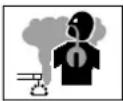
WARNING
FUMES AND GASES can be hazardous to your health.
Welding produces fumes and gases. Breathing these fumes and gases can be hazardous to your health.
- Keep your head out of the fumes. Do not breath the fumes.
- If inside, ventilate the area and/or use exhaust at the arc to remove welding fumes and gases.
- If ventilation is poor, use an approved air-supplied respirator.
- Read the Material Safety Data Sheets (MSDSs) and the manufacturer's instruction for metals, consumables, coatings, and cleaners.
- Work in a confined space only if it is well ventilated, or while wearing an air-supplied respirator. Shielding gases used for welding can displace air causing injury or death. Be sure the breathing air is safe.
- Do not weld in locations near degreasing, cleaning, or spraying operations. The heat and rays of the arc can react with vapours to form highly toxic and irritating gases.
- Do not weld on coated metals, such as galvanized, lead, or cadmium plated steel, unless the coating is removed from the weld area, the area is well ventilated, and if necessary, while wearing an air-supplied respirator. The coatings and any metals containing these elements can give off toxic fumes if welded.
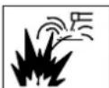
WARNING
WELDING can cause fire or explosion.
Sparks and spatter fly off from the welding arc. The flying sparks and hot metal, weld spatter, hot workpiece, and hot equipment can cause fires and burns. Accidental contact of electrode or welding wire to metal objects can cause sparks, overheating, or fire.
- Protect yourself and others from flying sparks and hot metal.
- Do not weld where flying sparks can strike flammable material.
-
Remove all flammables within 35 ft (10.7 m) of the welding arc. If this is not possible, tightly cover them with approved covers.
-
Be alert that welding sparks and hot materials from welding can easily go through small cracks and openings to adjacent areas.
- Watch for fire, and keep a fire extinguisher nearby.
- Be aware that welding on a ceiling, floor, bulk-head, or partition can cause fire on the hidden side.
- Do not weld on closed containers such as tanks or drums.
- Connect work cable to the work as close to the welding area as practical to prevent welding current from travelling long, possibly unknown paths and causing electric shock and fire hazards.
- Do not use welder to thaw frozen pipes.
- Remove stick electrode from holder or cut off welding wire at contact tip when not in use.

WARNING
FLYING SPARKS AND HOT METAL can cause injury.
Chipping and grinding cause flying metal. As welds cool, they can throw off slag.
- Wear approved face shield or safety goggles. Side shields recommended.
- Wear proper body protection to protect skin.
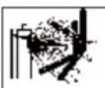
WARNING
CYLINDERS can explode if damaged.
Shielding gas cylinders contain gas under high pressure. If damaged, a cylinder can explode. Since gas cylinders are normally part of the welding process, be sure to treat them carefully
- Protect compressed gas cylinders from excessive heat, mechanical shocks, and arcs.
- Install and secure cylinders in an upright position by chaining them to a stationary support or equipment cylinder rack to prevent falling or tipping.
- Keep cylinders away from any welding or other electrical circuits.
- Never allow a welding electrode to touch any cylinder.
-
Use only correct shielding gas cylinders, regulators, hoses, and fittings designed for the specific application; maintain them and associated parts in good condition.
-
Turn face away from valve outlet when opening cylinder valve.
- Keep protective cap in place over valve except when cylinder is in use or connected for use.
- Read and follow instructions on compressed gas cylinders, associated equipment, and CGA publication P-1 listed in Safety Standards.

WARNING
MOVING PARTS can cause injury.
Moving parts, such as fans, rotors, and belts can cut fingers and hands and catch loose clothing.
- Keep all doors, panels, covers, and guards closed and securely in place.
- Stop engine before installing or connecting unit.
- Have only qualified people remove guards or covers for maintenance and troubleshooting as necessary.
- To prevent accidental starting during servicing, disconnect negative (-) battery cable from battery.
- Keep hands, hair, loose clothing, and tools away from moving parts.
- Reinstall panels or guards and close doors when servicing is finished and before starting engine.
WARNING
This product, when used for welding or cutting, produces fumes or gases which contain chemicals known to the State of California to cause birth defects and, in some cases, cancer. (California Health & Safety code Sec. 25249.5 et seq.)

NOTE!
Considerations About Welding And The Effects of Low Frequency Electric and Magnetic Fields.
The following is a quotation from the General Conclusions Section of the U.S. Congress, Office of Technology Assessment, Biological Effects of Power
Frequency Electric & Magnetic Fields - Background Paper, OTA-BP-E-63 (Washington, DC: U.S. Government Printing Office, May 1989): “...there is now a very large volume of scientific findings based on experiments at the cellular level and from studies with animals and people which clearly establish that low frequency magnetic fields and interact with, and produce changes in, biological systems. While most of this work is of very high quality, the results are complex. Current scientific understanding does not yet allow us to interpret the evidence in a single coherent framework. Even more frustrating, it does not yet allow us to draw definite conclusions about questions of possible risk or to offer clear science-based advice on strategies to minimize or avoid potential risks.”
To reduce magnetic fields in the workplace, use the following procedures.
- Keep cables close together by twisting or taping them.
- Arrange cables to one side and away from the operator.
- Do not coil or drape cable around the body.
- Keep welding power source and cables as far away from body as practical.
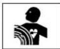
WARNING
The above procedures are among those also normally recommended for pacemaker wearers. Consult your doctor for complete information.
1.02 PRINCIPAL SAFETY STANDARDS
Safety in Welding and Cutting, ANSI Standard Z49.1, from American Welding Society, 550 N.W. LeJeune Rd., Miami, FL 33126.
Safety and Health Standards, OSHA 29 CFR 1910, from Superintendent of Documents, U.S. Government Printing Office, Washington, D.C. 20402.
Recommended Safe Practices for the Preparation for Welding and Cutting of Containers That Have Held Hazardous Substances, American Welding Society Standard AWS F4.1, from American Welding Society, 550 N.W. LeJeune Rd., Miami, FL 33126.
National Electrical Code, NFPA Standard 70, from National Fire Protection Association, Batterymarch Park, Quincy, MA 02269.
Safe Handling of Compressed Gases in Cylinders, CGA Pamphlet P-1, from Compressed Gas Association, 1235 Jefferson Davis Highway, Suite 501, Arlington, VA 22202.
Code for Safety in Welding and Cutting, CSA Standard W117.2, from Canadian Standards Association, Standards Sales, 178 Rexdale Boulevard, Rexdale, Ontario, Canada M9W 1R3.
Safe Practices for Occupation and Educational Eye and Face Protection, ANSI Standard Z87.1, from American National Standards Institute, 1430 Broadway, New York, NY 10018.
Cutting and Welding Processes, NFPA Standard 51B, from National Fire Protection Association, Battery-march Park, Quincy, MA 02269.
Safety in welding and allied processes Part 1: Fire Precautions, AS 1674.1-1997 from SAI Global Limited, www.saiglobal.com.
Safety in welding and allied processes Part 2: Electrical, AS 1674.2-2007 from SAI Global Limited, www.saiglobal.com.
Filters for eye protectors - Filters for protection against radiation generated in welding and allied operations AS/NZS 1338.1:1992 from SAI Global Limited, www.saiglobal.com.
This Page Intentionally Blank
SECTION 2:
INTRODUCTION
2.01 How To Use This Manual
This Owners Manual only applies to the Part Numbers listed on page i.
To ensure safe operation, read the entire manual, including the chapter on safety instructions and warnings.
Throughout this manual, the words WARNING, CAUTION, and NOTE may appear. Pay particular attention to the information provided under these headings. These special annotations are easily recognized as follows:

NOTE!
An operation, procedure, or background information which requires additional emphasis or is helpful in efficient operation of the system.
WARNING
A procedure which, if not properly followed, may cause injury to the operator or others in the operating area.
CAUTION
A procedure which, if not properly followed, may cause damage to the equipment.
WARNING
Gives information regarding possible electrical shock injury. Warnings will be enclosed in a box such as this.

DANGER
Means immediate hazards which, if not avoided, will result in immediate, serious personal injury or loss of life.
Additional copies of this manual may be purchased by contacting CIGWELD at the address and phone number for your location listed in the inside back cover of this manual. Include the Owner's Manual number and equipment identification numbers.
Electronic copies of this manual can also be downloaded at no charge in Acrobat PDF format by going to the CIGWELD web site listed below and clicking on the Literature Library link:
http://www.cigweld.com.au
2.02 Equipment Identification
The unit's identification number (specification or part number), model, and serial number usually appear on a nameplate attached to the control panel. In some cases, the nameplate may be attached to the rear panel. Equipment which does not have a control panel such as gun and cable assemblies is identified only by the specification or part number printed on the shipping container. Record these numbers on the bottom of page i for future reference.
2.03 Receipt Of Equipment
When you receive the equipment, check it against the invoice to make sure it is complete and inspect the equipment for possible damage due to shipping. If there is any damage, notify the carrier immediately to file a claim. Furnish complete information concerning damage claims or shipping errors to the location in your area listed in the inside back cover of this manual.
Include all equipment identification numbers as described above along with a full description of the parts in error.
Move the equipment to the installation site before un-crating the unit. Use care to avoid damaging the equipment when using bars, hammers, etc., to un-crate the unit.
2.04 Symbol Chart
Note that only some of these symbols will appear on your model.







On
Off
Dangerous Voltage
Increase/Decrease
Circuit Breaker
AC Auxiliary Power
Fuse
Amperage
Voltage
Hertz (cycles/sec)
Frequency
Negative
m = 311
Direct Current (DC)
Protective Earth (Ground)
Line
Line Connection
Auxiliary Power
Receptacle Rating- Auxiliary Power
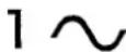
Single Phase
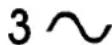
Three Phase
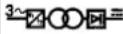
Three Phase Static Frequency Converter-Transformer-Rectifier

Remote

Duty Cycle

Percentage

Panel/Local

Shielded Metal Arc Welding (SMAW)

Gas Metal Arc Welding (GMAW)

Gas Tungsten Arc Welding (GTAW)

Air Carbon Arc Cutting (CAC-A)

Constant Current

Constant Voltage Or Constant Potential

High Temperature

Fault Indication
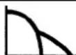
Arc Force

Touch Start (GTAW)
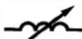
Variable Inductance
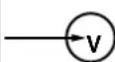
Voltage Input

Wire Feed Function

Wire Feed Towards Workpiece With Output Voltage Off.

Welding Gun

Purging Of Gas

Continuous Weld Mode

Spot Weld Mode

Spot Time

Preflow Time

Postflow Time


2 Step Trigger Operation
Press to initiate wirefeed and welding, release to stop.


4 Step Trigger Operation
Press and hold for preflow, release to start arc. Press to stop arc, and hold for preflow.

Burnback Time

Disturbance In Ground System

Inches Per Minute

Metres Per Minute

Spool Gun
Art # A-04937 AB
2.05 Description
This CIGWELD WeldSkill 155 and 185 offer the many benefits of a professional welding machine in a compact, portable, easy to use and affordable self-contained single phase welding inverter. Ideal for welders who want to do light fabrication, maintenance and repairs or DIY around the home without compromising on quality or safety. These multi-process welding inverters are capable of performing MIG (FCAW/GMAW), Stick (MMAW) and Lift TIG (GTAW) welding processes. The Weldskill 155 and 185 are backed by a 2 year warranty*, equipped with a 10Amp plug, digital voltage and amperage meters, an integrated wire feed unit, Voltage Reduction Device (VRD applicable in Stick mode only), quick connect gas connection and a host of other features. And most importantly the two models are fully compliant to Australian Standard AS 60974.1 and IEC 60974.1.
The WeldSkill 155 and 185 provide excellent welding performance across a broad range of applications when used with the correct welding consumables and procedures. The following instructions detail how to correctly and safely set up the machine and give guidelines on gaining the best efficiency and quality from the power sources. Please read these instructions thoroughly before using the units.

\*NOTE
Refer to the complete Warranty Schedule at the back of the manual..
2.06 User Responsibility
This equipment will perform as per the information contained herein when installed, operated, maintained and repaired in accordance with the instructions provided. This equipment must be checked periodically. Defective equipment (including welding leads) should not be used. Parts that are broken, missing, plainly worn, distorted or contaminated, should be replaced immediately. Should such repairs or replacements become necessary, it is recommended that such repairs be carried out by appropriately qualified persons approved by CIGWELD. Advice in this regard can be obtained by contacting accredited CIGWELD Distributor.
This equipment or any of its parts should not be altered from standard specification without prior written approval of CIGWELD. The user of this equipment shall have the sole responsibility for any malfunction which results from improper use or unauthorised modification from standard specification, faulty maintenance, damage or improper repair by anyone other than appropriately qualified persons approved by CIGWELD.
2.07 Packaged Item
WeldSkill 155 Inverter (Part No. W1008155)
• WeldSkill 155 Inverter Power Source
• 3m Lead with Twist Lock Electrode Holder
• 3m Lead with Work Clamp
• E-180 MIG torch, 3m, Euro
- Feed Rolls: 0.8/0.9 Flux Cored (fitted) 0.8/0.9 V Groove
- Shielding Gas Hose
• Cutskill Argon Regulator/Flowmeter
- Operating Manual
WeldSkill 185 Inverter (Part No. W1008185)
• WeldSkill 185 Inverter Power Source
• 3m Lead with Twist Lock Electrode Holder
• 3m Lead with Work Clamp
• E-180 MIG torch, 3m, Euro
- Feed Rolls: 0.8/0.9 Flux Cored (fitted) 0.8/0.9 V Groove
- Shielding Gas Hose
• Cutskill Argon Regulator/Flowmeter
- Operating Manual
2.08 Transporting Methods
These units are equipped with a handle for carrying purposes.
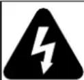
WARNING
ELECTRIC SHOCK can kill. DO NOT TOUCH live electrical parts. Disconnect input power conductors from de-energized supply line before moving the welding power source.
WARNING
FALLING EQUIPMENT can cause serious personal injury and equipment damage.
Lift unit with handle on top of case.
Use handcart or similar device of adequate capacity.
If using a fork lift vehicle, place and secure unit on a proper skid before transporting.
2.09 Duty Cycle
The rated duty cycle of a Welding Power Source, is a statement of the time it may be operated at its rated welding current output without exceeding the temperature limits of the insulation of the component parts. To explain the 10 minute duty cycle period the following example is used. Suppose a Welding Power Source is designed to operate at a 15% duty cycle, 90 amperes at 23.6 volts. This means that it has been designed and built to provide the rated amperage (90A) for 1.5 minutes, i.e. arc welding time, out of every 10 minute period (15% of 10 minutes is 1.5 minutes). During the other 8.5 minutes of the 10 minute period the Welding Power Source must idle and allowed to cool.
2.10 Specifications
| Description | WeldSkill 155 WeldSkill 185 | |
| Part Number W1008155 W1008185 | ||
| Power Source Dimensions H371mmxW205mmxD478mm H371mmxW205mmxD478mm | ||
| Power Source Weight 13.7 KG 13.7 KG | ||
| Cooling Fan Cooled Fan Cooled | ||
| Welder Type Multi Process Inverter PowerSource | Multi Process Inverter PowerSource | |
| Australian Standard AS 60974.1-2006 / IEC 60974-1 AS 60974.1-2006 / IEC 60974-1 | ||
| Number of Phases | Single Phase | Single Phase |
| Nominal Supply Voltage | 240V AC ± 15% | 240V AC ± 15% |
| Nominal Supply Frequency | 50/60 Hz | 50/60 Hz |
| Welding Current Range (MIG mode) | 30 - 155 A 30 - 185 A | |
| Nominal DC Open Circuit Voltage MIG Weld Mode | 69 V(Trigger Switch Depressed when not Welding) | 69 V(Trigger Switch Depressed when not Welding) |
| Open Circuit Voltage (VRD On) Stick Weld Mode | <35 V | <35 V |
| Open Circuit Voltage (VRD Off) Stick Weld Mode | 69 V | 69 V |
| Effective Input Current ( I_1eff ) refer Note 2 | 10 Amps | 10 Amps |
| Maximum Input Current ( I_1max ) | 35 Amps | 40 Amps |
| Minimum Single Phase Generator Recommendation (refer Note 4) | 8.0 kVA (at 0.8 Power Factor)6.0 kW (at 1.0 Power Factor) | 10.0 kVA (at 0.8 Power Factor)8.0 kW (at 1.0 Power Factor) |
| MIG (GMAW) Welding Output, 40°C, 10 min. | 155 A @15%, 21.8V | 185 A @10%, 23.3 V |
| 85 A @ 60%, 18.3V | 85 A @60%, 18.3 V | |
| 66 A @ 100%, 17.3V | 66 A @100%, 17.3 V | |
| STICK (MMAW) Welding Output, 40°C, 10 min. | 135 A @ 15%, 25.4 V | 160 A @ 10%, 26.4 V |
| 67 A @ 60%, 22.7 V | 65 A @ 60%, 22.6 V | |
| 52 A @ 100%, 22.1 V | 50 A @ 100%, 22 V | |
| TIG (GTAW) Welding Output, 40°C, 10 min. | 135 A @ 25%, 15.4 V | 160 A @ 20%, 16.4 V |
| 86 A @ 60%, 13.4 V | 93 A @ 60%, 13.7 V | |
| 67 A @ 100%, 12.7 V | 72 A @ 100%, 12.9 V | |
| Protection Class | IP21S | IP21S |
Table 2-1: Specifications

NOTE 1
Due to variations that can occur in manufactured products, claimed performance, voltages, ratings, all capacities, measurements, dimensions and weights quoted are approximate only. Achievable capacities and ratings in use and operation will depend upon correct installation, use, applications, maintenance and service.

NOTE 2
The Effective Input Current should be used for the determination of cable size & supply requirements.

NOTE 3
Motor start fuses or thermal circuit breakers are recommended for this application. Check local requirements for your situation in this regard.

NOTE 4
Minimum Generator Recommendation at the Maximum Output Duty Cycle.
Due to large variations in performance and specifications of different brands and types of generators, CIGWELD cannot guarantee full welding output power or duty cycle on every brand or type of generator.
Some small generators incorporate low cost circuit breakers on their outputs. These circuit breakers usually will have a small reset button, and will trip much faster than a switchboard type circuit breaker. This may result in not being able to achieve full output or duty cycle from the power source / generator combination. For this reason we recommend a generator that incorporates switchboard type circuit breakers.
CIGWELD recommends that when selecting a generator, that the particular power source / generator combination be adequately trialled to ensure the combination performs to the users expectations.

NOTE 5
CIGWELD reserves the right to change product performance and specifications without notice.

NOTE 6
If an extension lead is required to be used it is recommended to use a minimum size of 1.5mm^2 Heavy Duty Extension Lead. Longer extension leads may impact welding performance and operation.
2.11 Optional Accessories
We recommend genuine CIGWELD products.
The biggest range and best quality with guaranteed performance.
| Part Number Description | |
| W4018800 E-1 | 80 Mig Torch 3m, Euro (suits WeldSkill 155 & 185) |
| W6000600 Nozzle | |
| OTW11/23/R Contact Tip 0.6mm | |
| OTW11/30/R Contact Tip 0.8mm | |
| OTW11/35/R Contact Tip 0.9mm | |
| OTW11/40/R Contact Tip 1.0mm | |
| OTW11/45/R Contact Tip 1.2mm | |
| W6000606 Gas Diffuser | |
| WS1240015/R Conduit Liner Steel 5m, 0.6-1.0mm Blue (hard wires) | |
| WS1240031/R Conduit Liner Steel 4m, 1.0-1.2mm Red (hard wires) | |
| WS1260026/R Conduit Liner Teflon 4m, 0.8-1.2mm Red (soft wires) | |
| WS0010304/R Jump Liner 1.0-1.2mm | |
| 7977732 Feed | Roll 0.8/0.9mm V groove knurled (flux cored) (fitted) |
| 704277 Feed | Roll 1.2/1.6mm V groove knurled (flux cored) |
| 7977036 Feed | Roll 0.6/0.8mm V groove (hard wires) |
| 7977660 Feed | Roll 0.9/1.2mm V groove (hard wires) |
| 7977731 Feed | Roll 0.8/0.9mm U groove (soft wires) |
| 7977264 Feed | Roll 1.0/1.2mm U groove (soft wires) |
| W7003021 TIG | Torch 17V, flex neck, 3m lead with 50mm2 dinse (suits WeldSkill 155) |
| W4013801 TIG | Torch 17V with 4m lead and gas valve (suits WeldSkill 185) |
| W4013800 TIG | Torch 17V with 4m lead and gas valve and remote control (suits WeldSkill 185) |
| BGSAK2 TIG | Torch Accessory Kit for 17, 26 & 18 TIG Torches |
| W4011250 Tweco SGT250 Spool Gun (suits WeldSkill 185) | |
| 210254 CutSkill Argon Regulator/Flowmeter | |
| WSPLIER MIG | Pliers |
| W7004913 Shielding Gas Hose Assembly | |
| W4011501 Weld Skill Welding Equipment Trolley | |
| WS42550 | WeldSkill Welding Leadset 4m, 25mm ^2 cable, 50mm ^2 dinse, 250A Twistlock Electrode Holder |
| WS53550 | WeldSkill Welding Leadset 5m, 35mm ^2 cable, 50mm ^2 dinse, 400A Twistlock Electrode Holder |
Table 2-2
TIG Torch Consumables
| Part Number Description |
| BG10N49/R Nozzle Alumina 8mm, for 17, 26 & 18 TIG Torches (pkt of 5) |
| BG10N48/R Nozzle Alumina 10mm, for 17, 26 & 18 TIG Torches (pkt of 5) |
| BG10N47/R Nozzle Alumina 11mm, for 17, 26 & 18 TIG Torches (pkt of 5) |
| BG10N46/R Nozzle Alumina 12.5mm, for 17, 26 & 18 TIG Torches (pkt of 5) |
| BG10N22/R Collet 1.0mm, for 17, 26 & 18 TIG Torches (pkt of 5) |
| BG10N23/R Collet 1.6mm, for 17, 26 & 18 TIG Torches (pkt of 5) |
| BG10N24/R Collet 2.4mm, for 17, 26 & 18 TIG Torches (pkt of 5) |
| BG10N25/R Collet 3.2mm, for 17, 26 & 18 TIG Torches (pkt of 5) |
| BG10N30/R Collet Body 1.0mm, for 17, 26 & 18 TIG Torches (pkt of 5) |
| BG10N31/R Collet Body 1.6mm, for 17, 26 & 18 TIG Torches (pkt of 5) |
| BG10N32/R Collet Body 2.4mm, for 17, 26 & 18 TIG Torches (pkt of 5) |
| BG10N28/R Collet Body 3.2mm, for 17, 26 & 18 TIG Torches (pkt of 5) |
| BG57Y02/R Back Cap – Long for 17, 26 & 18 TIG Torches (pkt of 2) |
| BG57Y04/R Back Cap – Short for 17, 26 & 18 TIG Torches (pkt of 2) |
Table 2-3
TIG Electrodes
| Part Number Description |
| 699846 Ceriated Electrode 1.6mm x 175mm AC/DC Grey (Pkt of 10) |
| 699847 Ceriated Electrode 2.4mm x 175mm AC/DC Grey (Pkt of 10) |
| 699848 Ceriated Electrode 3.2mm x 175mm AC/DC Grey (Pkt of 10) |
Table 2-4
Related Products
| Part Number Description | |
| 646754 Weld | Skill TIG Welding Gloves |
| 646755 Weld | Skill Heavy Duty Welding Gloves |
| 454304 Weld | Skill Auto Darkening Welding Helmet Fixed Shade 11 Black |
| 454305 Weld | Skill Auto Darkening Welding Helmet Variable Shade 9-13 Blue |
| 454314 Weld | Skill Auto Darkening Welding Helmet Variable Shade 9-13 Carbon Fibre |
| 454321 Weld | Skill Auto Darkening Welding Helmet Variable Shade 9-13 Racer |
| 454322 Weld | Skill Auto Darkening Welding Helmet Variable Shade 9-13 Tribal |
| 454323 Weld | Skill Auto Darkening Welding Helmet Variable Shade 9-13 White Carbon |
| 454324 Weld | Skill Auto Darkening Welding Helmet Variable Shade 9-13 Oz Flag |
| Note: CIGWELD Electrodes see page 6-2 | |
Table 2-5
This Page Intentionally Blank.
SECTION 3:
INSTALLATION
3.01 Environment
These units are designed for use in environments with increased hazard of electric shock.
A. Examples of environments with increased hazard of electric shock are:
1. In locations in which freedom of movement is restricted, so that the operator is forced to perform the work in a cramped (kneeling, sitting or lying) position with physical contact with conductive parts.
2. In locations which are fully or partially limited by conductive elements, and in which there is a high risk of unavoidable or accidental contact by the operator.
B. Environments with increased hazard of electric shock do not include places where electrically conductive parts in the near vicinity of the operator, which can cause increased hazard, have been insulated.
3.02 Location
Be sure to locate the welder according to the following guidelines:
A. In areas, free from moisture and dust.
B. Ambient temperature between -10^ C to 40^ C.
C. In areas, free from oil, steam and corrosive gases.
D. In areas, not subjected to abnormal vibration or shock.
E. In areas, not exposed to direct sunlight or rain.
F. Place at a distance of 300mm or more from walls or similar that could restrict natural air flow for cooling.
3.03 Ventilation
Since the inhalation of welding fumes can be harmful, ensure that the welding area is effectively ventilated.
3.04 Mains Supply Voltage Requirements
The Mains Supply Voltage should be within ± 15% of the rated Mains Supply Voltage. If actual Mains Supply Voltage is outside this range Welding Current may not be available and may cause internal components to fail.
Refer to Specifications on page 2-4 for Supply Voltage information.
The Welding Power Source must be:
- Correctly installed, if necessary, by a qualified electrician.
- Correctly earthed (electrically) in accordance with local regulations.
- Connected to the correct size power point and fuse as per the Specifications on page 2-4.

IMPORTANT NOTE!
This product has been fitted with a supply plug as indicated in Section 2.10. Note that the welding output range applicable with the fitted supply plug is detailed in Section 2.10.
WARNING
Any electrical work must be carried out by a qualified Electrical Tradesperson.
3.05 Generators
Refer to Note 4 on page 2-5 for recommendations when using with a Generator.
3.06 Extension Leads
If an extension lead is required to be used it is recommended to use a minimum size of 1.5mm^2 Heavy Duty Extension Lead. Longer extension leads may impact welding performance and operation.
3.07 Electromagnetic Compatibility
WARNING
Extra precautions for Electromagnetic Compatibility may be required when this Welding Power Source is used in a domestic situation.
A. Installation and Use - Users Responsibility
The user is responsible for installing and using the welding equipment according to the manufacturer's instructions. If electromagnetic disturbances are detected then it shall be the responsibility of the user of the welding equipment to resolve the situation with the technical assistance of the manufacturer. In some cases this remedial action may be as simple as earthing the welding circuit, see NOTE below. In other cases it could involve constructing an electromagnetic screen enclosing the Welding Power Source and the work, complete with associated input filters. In all cases, electromagnetic disturbances shall be reduced to the point where they are no longer troublesome.

NOTE!
The welding circuit may or may not be earthed for safety reasons. Changing the earthing arrangements should only be authorised by a person who is competent to assess whether the changes will increase the risk of injury, e.g. by allowing parallel welding current return paths which may damage the earth circuits of other equipment. Further guidance is given in IEC 974-13 Arc Welding Equipment - Installation and use (under preparation).
B. Assessment of Area
Before installing welding equipment, the user shall make an assessment of potential electromagnetic problems in the surrounding area. The following shall be taken into account
- Other supply cables, control cables, signalling and telephone cables; above, below and adjacent to the welding equipment.
- Radio and television transmitters and receivers.
- Computer and other control equipment.
- Safety critical equipment, e.g. guarding of industrial equipment.
- The health of people around, e.g. the use of pacemakers and hearing aids.
-
Equipment used for calibration and measurement.
-
The time of day that welding or other activities are to be carried out.
- The immunity of other equipment in the environment: the user shall ensure that other equipment being used in the environment is compatible: this may require additional protection measures.
The size of the surrounding area to be considered will depend on the structure of the building and other activities that are taking place. The surrounding area may extend beyond the boundaries of the premises.
C. Methods of Reducing Electromagnetic Emissions
1. Mains Supply
Welding equipment should be connected to the mains supply according to the manufacturer's recommendations. If interference occurs, it may be necessary to take additional precautions such as filtering of the mains supply. Consideration should be given to shielding the supply cable of permanently installed welding equipment in metallic conduit or equivalent. Shielding should be electrically continuous throughout its length. The shielding should be connected to the Welding Power Source so that good electrical contact is maintained between the conduit and the Welding Power Source enclosure.
2. Maintenance of Welding Equipment
The welding equipment should be routinely maintained according to the manufacturer's recommendations. All access and service doors and covers should be closed and properly fastened when the welding equipment is in operation. The welding equipment should not be modified in any way except for those changes and adjustments covered in the manufacturer's instructions. In particular, the spark gaps of arc striking and stabilising devices should be adjusted and maintained according to the manufacturer's recommendations.
3. Welding Cables
The welding cables should be kept as short as possible and should be positioned close together, running at or close to the floor level.
Bonding of all metallic components in the welding installation and adjacent to it should be considered. However, Metallic components bonded to the work piece will increase the risk that the operator could receive a shock by touching the metallic components and the electrode at the same time. The operator should be insulated from all such bonded metallic components.
5. Earthing of the Workpiece
Where the workpiece is not bonded to earth for electrical safety, nor connected to earth because of its size and position, e.g. ship's hull or building steelwork, a connection bonding the workpiece to earth may reduce emissions in some, but not all instances. Care should be taken to prevent the earthing of the workpiece increasing the risk of injury to users, or damage to other electrical equipment. Where necessary, the connection of the workpiece to earth should be made by direct connection to the workpiece, but in some countries where direct connection is not permitted, the bonding should be achieved by suitable capacitance, selected according to national regulations.
6. Screening and Shielding
Selective screening and shielding of other cables and equipment in the surrounding area may alleviate problems of interference. Screening the entire welding installation may be considered for special applications.
This Page Intentionally Blank
Conventional operating procedures apply when using the Welding Power Source, i.e. connect work lead directly to workpiece and the electrode wire is fed via the MIG Torch (Consult the electrode wire manufacturers information for the correct polarity). The welding current range values should be used as a guide only. Current delivered to the arc is dependent on the welding arc voltage, and as welding arc voltage varies between different classes of electrode wire, welding current at any one setting would vary accordingly to the type of electrode wire in use. The operator should use the welding current range values as a guide, then fianlly adjust the current setting to suit the application.
4.02 Power Source Controls, Indicators and Features
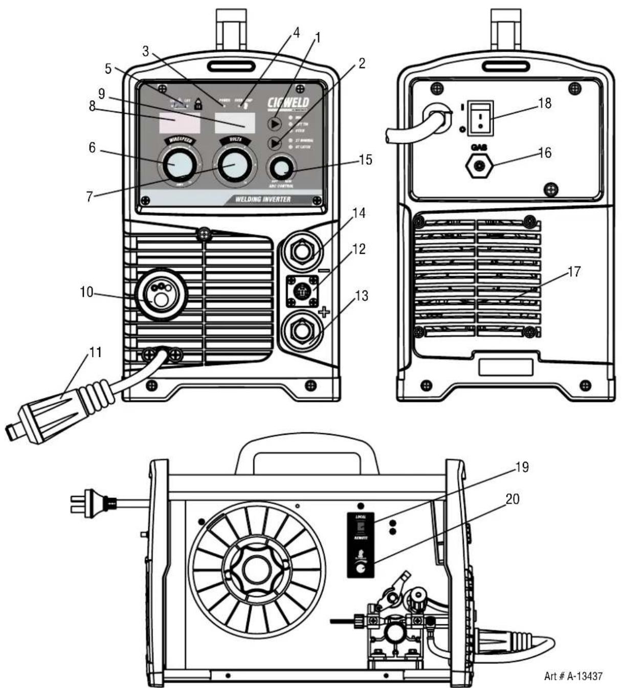
Figure 4-1 WeldSkill 185 as Pictured
1. Process Selection Control
The process selection control is used to select the desired welding mode. Three modes are available, MIG (GMAW/FCAW), Lift TIG (GTAW), STICK (MMAW) modes. Refer to section 5.09 or 5.10 for MIG (GMAW/FCAW) set up details, section 7.02 for Lift TIG (GTAW) set-up details or section 6.01 for Stick (MMAW) set-up details.
Note that when the unit is powered off the mode selection control will automatically default to MIG mode. This is necessary so as to prevent inadvertent arcing should an electrode holder be connected to the unit and mistakenly be in contact with the work piece during power up.
2. Trigger Mode Control (MIG and Lift TIG Modes WeldSkill 185 only)
The trigger mode control is used to switch the functionality of the torch trigger between 2T (normal) and 4T (latch mode).
2T Normal Mode
In this mode, the torch trigger must remain depressed for the welding output to be active. Press and hold the torch trigger to activate the power source (weld). Release the torch trigger switch to cease welding.
4T Latch Mode
This mode of welding is mainly used for long welding runs to reduce operator fatigue. In this mode the operator can press and release the torch trigger and the output will remain active. To deactivate the power source, the trigger switch must again be depressed and released, thus eliminating the need for the operator to hold the torch trigger.
3. Power Indicator
The power indicator is illuminated when nominal 240V AC mains power is applied to the power source and the ON/OFF switch located on the rear panel is in the ON position.
4. Over Temp Indicator
This welding power source is protected by a self resetting thermostat. The Over Temp indicator will illuminate if the machine has over heated which normally occurs if the duty cycle of the power source has been exceeded. Should the Over Temp indicator illuminate the output of the power source will be disabled. Leave the power source turned On to allow the internal components to cool down. Once the power source cools down sufficiently the Over Temp indicator will automatically go off. Note that the On/Off switch should remain in the On position such that the fan continues to operate thus allowing the power source to cool sufficiently. Do not switch the power source Off if an Over Temp condition is present.
5. VRD ON/OFF Indicator Lights
A VRD (voltage reduction device) is a hazard reducing device designed to reduce electric shock hazards present on the output of welding power source when operating in STICK (MMAW) mode. Note that the presence of VRD should not be used as a substitute for the use of appropriate safety practices as indicated in Section One of this manual.
The green VRD ON light illuminates (red light is off) when the VRD is active. Under this condition the open circuit voltage of the unit is limited to below 35V DC, thus reducing the potential of serious electric shock (such as when changing electrodes).
The red VRD OFF light illuminates (green light is off) when the VRD is inactive. Under this condition the output voltage of the unit will be at welding potential which in some cases may exceed 35V DC.
6. Wirespeed Control (MIG) Amps Control (Stick & TIG)
In MIG (GMAW/FCAW) modes, the Wirespeed Control knob adjusts the speed of the wire feed motor (which in turn adjusts the output current by varying the amount of MIG wire delivered to the welding arc). The optimum wire speed required will depend on the type of welding application. The setup guide on the inside of the wire feed compartment door provides a brief summary of the required output settings for a basic range of MIG welding applications.
The amps control knob adjusts the amount of welding current delivered by the power source. In Stick (MMAW) and TIG (GTAW) modes, the Amps control knob directly adjusts the power inverter to deliver the desired level of output current.
7. Voltage Control
In MIG (GMAW/FCAW) mode, the voltage control knob is used to adjust the output voltage of the unit. The welding voltage is increased by turning the knob clockwise or decreased by turning the knob anti-clockwise. The optimum voltage level required will be dependent on the type of welding application. The setup chart on the inside of the wire feed compartment door provides a brief summary of the required output settings for a basic range of MIG welding applications.
8. Digital Amps Meter (Left Digital Display)
MIG Mode
This digital meter is used to display the pre-set (preview) Wirefeed Speed in Metres Per Minute (MPM) in MIG mode and actual welding amperage of the power source when welding. At times of non-welding, the digital meter will display a pre-set (preview) value of Wirefeed Speed (MPM). This value can be adjusted by varying the Wirespeed Control Knob (6).
STICK and LIFT TIG Modes
The digital meter is used to display the pre-set (preview) amperage in STICK / LIFT TIG modes and actual welding amperage of the power source when welding. At times of non-welding, the amperage meter will display a pre-set (preview) amperage value in both STICK and LIFT TIG modes. This value can be adjusted by varying the Amps Control Knob (6).
When welding, this digital meter will display actual welding amperage in all modes.
At the completion of welding, the digital meter will hold the last recorded amperage value for a period of approximately 10 seconds in all modes. The amperage meter will hold the value until; (1) any of the front panel controls are adjusted in which case the unit will revert to preview mode, (2) welding is recommenced, in which case actual welding amperage will be displayed, or (3) a period of 10 seconds elapses following the completion of welding in which case the unit will return to preview mode.

NOTE
The preview functionality provided on this power source is intended to act as a guide only. Some differences may be observed between preview values and actual welding values due to factors including the mode of welding, differences in consumables/gas mixtures, individual welding techniques and the transfer mode of the welding arc (ie dip versus spray transfer). Where exact settings are required (in the case of procedural work), it is recommended that alternate measurement methods be utilised to ensure output values are accurate.
9. Digital Voltage Meter (Right Digital Display)
MIG Mode
This digital meter is used to display the pre-set (preview) Voltage in MIG mode and actual welding voltage of the power source when welding. At times of non-welding, the digital meter will display a pre-set (preview) value of Voltage. This value can be adjusted by varying the Voltage Control Knob (7).
STICK and LIFT TIG Modes
This digital meter is used to display the Welding Output Terminal Voltage in STICK / LIFT TIG modes during non-welding or welding. This value Cannot be adjusted by varying the Voltage Control Knob (7). When welding, this digital meter will display actual welding voltage in all modes.
At the completion of welding, the digital meter will hold the last recorded voltage value for a period of approximately 10 seconds in all modes. The voltage meter will hold the value until; (1) any of the front panel controls are adjusted in which case the unit will revert to preview mode, (2) welding is recommenced, in which case actual welding amperage will be displayed, or (3) a period of 10 seconds elapses following the completion of welding in which case the unit will return to preview mode.

NOTE
The preview functionality provided on this power source is intended to act as a guide only. Some differences may be observed between preview values and actual welding values due to factors including the mode of welding, differences in consumables/gas mixtures, individual welding techniques and the transfer mode of the welding arc (ie dip versus spray transfer). Where exact settings are required (in the case of procedural work), it is recommended that alternate measurement methods be utilised to ensure output values are accurate.
10. MIG Torch Adaptor (Euro Style)
The MIG torch adaptor is the connection point for the MIG welding torch. Connect the torch by pushing the torch connector into the brass torch adaptor firmly and screwing the plastic torch nut clockwise to secure in position. To remove the MIG torch simply reverse these directions.
11. MIG Torch Polarity Lead
The polarity lead is used to connect the MIG torch to the appropriate positive or negative output terminal (allowing polarity reversal for different welding applications). In general, the polarity lead should be connected in to the positive welding terminal (+) when using steel, stainless steel or aluminium electrode wire. When using gasless wire, the polarity lead is generally connected to the negative welding terminal (-). If in doubt, consult the manufacturer of the electrode wire for the correct polarity. It is essential, however, that the male plug is inserted and turned securely to achieve a sound electrical connection.

CAUTION
Loose welding terminal connections can cause overheating and result in the male plug being fused in the Dinse terminal.
12. Remote Control Socket (WeldSkill 185 only)
The 8 pin Remote Control Socket is used to connect remote control devices (i.e. Spool Gun or Tig Torch) to the welding power source. To make connections, align keyway, insert plug, and rotate threaded collar fully clockwise.
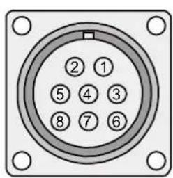
A-13456
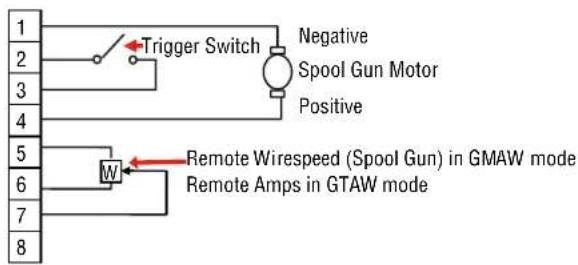
| Socket Pin | Function |
| 1 Spool | gun motor negative |
| 2 | Trigger Switch Input |
| 3 | Trigger Switch Input |
| 4 | Spool gun motor positive |
| 5 | 5k ohm (maximum) connection to 5k ohm remote control potentiometer. |
| 6 | Zero ohm (minimum) connection to 5k ohm remote control potentiometer. |
| 7 | Wiper arm connection to 5k ohm remote control Wirespeed MIG (GMAW) mode potentiometer.Wiper arm connection to 5k ohm remote control Amps TIG (GTAW) mode potentiometer. |
| 8 | Not connected |
Table 4-1
Note that the remote/local switch (item 19) located in the wirefeed compartment should be set to remote for the amperage/voltage controls to be operative.
13. Positive Welding Output Terminal
The positive welding terminal is used to connect the welding output of the power source to the appropriate welding accessory such as the MIG torch (via the MIG torch polarity lead), electrode holder lead or work lead. Positive welding current flows from the power source via this Dinse terminal. It is essential, however, that the male plug is inserted and turned securely to achieve a sound electrical connection.

CAUTION
Loose welding terminal connections can cause overheating and result in the male plug being fused in the Dinse terminal.
14. Negative Welding Output Terminal
The negative welding terminal is used to connect the welding output of the power source to the work lead. Most General Purpose electrodes are connected with work lead to negative. Consult the electrode manufacturer's information for the correct polarity.
Welding current flows from the workpiece via this Dinse type terminal to the power source. It is essential, however, that the male dinse type plug is inserted and turned securely to achieve a sound electrical connection. Do not over tighten.
CAUTION
Loose welding terminal connections can cause overheating and result in the male plug being fused in the Dinse terminal.
15. Arc Control (Inductance)
The arc control operates in MIG(GMAW) mode only and is used to adjust the intensity of the welding arc. Lower arc control settings make the arc softer with less weld spatter. Higher arc control settings give a stronger driving arc which can increase weld penetration.
16. Gas Inlet (MIG mode only)
The Gas Inlet connection is a quick connect type inlet fitting used to supply the appropriate MIG welding gas to the unit. Refer to section 5.09 for MIG set up details.
WARNING
Only Inert Shielding Gases specifically designed for welding applications should be used.
17. Fan
The Fan is turned ON/OFF by the Power Switch on the rear panel of the machine.
18. On/Off Switch
This switch is used to turn the unit ON/OFF. When this switch is turned ON the Power Indicator on the front panel will illuminate.

NOTE
If the Power Source is repeatedly switched On then Off rapidly or the supply to the power source is turned On and Off rapidly it may not turn On due to inbuilt protective devices acting. If this occurs leave the Power Source On/Off switch turned to the Off position for several minutes to allow for the protective devices to reset.
19. Local / Remote Switch (located in wirefeed compartment of WeldSkill 185 only)
The Local / Remote switch is used only when the unit is in Lift Tig Mode and a Tig Torch with Remote Current Control or the unit is in Mig Mode and a Spool Gun is fitted to the unit via the 8 Pin remote control socket (item 12) located on the front panel. When the Local/Remote switch is in the Remote position, the unit will detect the remote device and work accordingly. When in the Local Mode, the unit will not detect the remote device and will operate from the power source controls only. Note that the trigger will operate at all times on the remote control socket irrespective of the position of the Local / Remote switch (ie in both local and remote modes).
When the Local/Remote switch is set to Remote mode, if the unit is in Lift Tig mode and a Tig Torch with Remote Current Control is connected the current output value will be controlled only by the Tig Torch Remote Control. If the unit is in Mig Mode and a Spool Gun fitted with wirespeed control is connected the Spool Gun wirefeed speed will be controlled by the Spool Gun Control. The power source control will be disabled.
20. Burnback Control (located in wirefeed compartment)
The burnback control is used to adjust the amount of MIG wire that protrudes from the MIG torch after the completion of MIG welding (commonly referred to as stick out). To decrease the burnback time (or lengthen the amount of wire protruding from the MIG torch at the completing of welding), turn the burnback control knob anti clockwise. To increase the burnback time (or shorten the amount of wire protruding from the torch at the completing of welding), turn the Burnback Control knob clockwise.
21. Hot Start Feature (Not Shown)
This feature operates in Stick (MMAW) mode. The Hot Start feature improves the arc start characteristics by momentarily increasing the welding current to a level above the preset amperage (Welding Current). This is a preset feature and is not adjustable.
22. Anti Stick Feature (Not Shown)
This feature operates in Stick (MMAW) mode.
The anti stick feature senses when the electrode sticks and automatically reduces the current to prevent the Stick Electrode from sticking to the work piece. This is a preset feature and is not adjustable.
SECTION 5:
MIG (GMAW) WELDING
5.01 Shielding Gas Regulator/Flowmeter Operating Instructions
WARNING
This equipment is designed for use with welding grade (Inert) shielding gases only..
Shielding Gas Regulator/Flowmeter Safety
This regulator/flowmeter is designed to reduce and control high pressure gas from a cylinder or pipeline to the working pressure required for the equipment using it.
If the equipment is improperly used, hazardous conditions are created that may cause accidents. It is the users responsibility to prevent such conditions. Before handing or using the equipment, understand and comply at all times with the safe practices prescribed in this instruction.
SPECIFIC PROCEDURES for the use of regulators/flowmeters are listed below.
- NEVER subject the regulator/flowmeter to inlet pressure greater than its rated inlet pressure.
- NEVER pressurize a regulator/flowmeter that has loose or damaged parts or is in a questionable condition. NEVER loosen a connection or attempt to remove any part of a regulator/flowmeter until the gas pressure has been relieved. Under pressure, gas can dangerously propel a loose part.
- DO NOT remove the regulator/flowmeter from a cylinder without first closing the cylinder valve and releasing gas in the regulator/flowmeter high and low pressure chambers.
- DO NOT use the regulator/flowmeter as a control valve. When downstream equipment is not in use for extended periods of time, shut off the gas at the cylinder valve and release the gas from the equipment.
- OPEN the cylinder valve SLOWLY. Close after use.
User Responsibilities
This equipment will perform safely and reliable only when installed, operated and maintained, and repaired in accordance with the instructions provided. Equipment must be checked periodically and repaired, replaced, or reset as necessary for continued safe and reliable performance. Defective equipment should not be used. Parts that are broken, missing, obviously worn, distorted, or contaminated should be replaced immediately.
The user of this equipment will generally have the sole responsibility for any malfunction, which results from improper use, faulty maintenance, or by repair by anyone other than an accredited repairer.

CAUTION
Match regulator/flowmeter to cylinder. NEVER CONNECT a regulator/flowmeter designed for a particular gas or gases to a cylinder containing any other gas.
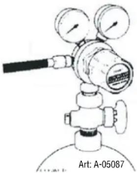
natural_image
Illustration of a gas regulator with pressure gauge and valve (no text or symbols on the diagram itself)Figure 5-1: Fit Regulator/flowmeter to Cylinder
Installation
- Remove cylinder valve plastic dust seal. Clean the cylinder valve outlet of impurities that may clog orifices and damage seats before connecting the regulator/flowmeter.
Crack the valve (open then close) momentarily, pointing the outlet away from people and sources of ignition. Wipe with a clean lint free cloth.
- Match regulator/flowmeter to cylinder. Before connecting, check that the regulator/flowmeter label and cylinder marking agree and that the regulator/flowmeter inlet and cylinder outlet match. NEVER CONNECT a regulator/flowmeter designed for a particular gas or gases to a cylinder containing any other gas.
- Connect the regulator/flowmeter inlet connection to cylinder or pipeline and tighten it firmly but not excessively, with a suitable spanner.
- Connect and tighten the outlet hose firmly and attach down-stream equipment.
- To protect sensitive down-stream equipment a separate safety device may be necessary if the regulator/flowmeter is not fitted with a pressure relief device.
Operation
With the regulator/flowmeter connected to cylinder or pipeline, and the adjustment screw/knob fully disengaged, pressurize as follows:
- Stand to one side of regulator/flowmeter and slowly open the cylinder valve. If opened quickly, a sudden pressure surge may damage internal regulator/flowmeter parts.
- With valves on downstream equipment closed, adjust regulator/flowmeter to approximate working pressure. It is recommended that testing for leaks at the regulator/flowmeter connection points be carried out using a suitable leak detection solution or soapy water.
- Purge air or other unwanted welding grade shielding gas from equipment connected to the regulator/flowmeter by individually opening then closing the equipment control valves. Complete purging may take up to ten seconds or more, depending upon the length and size of the hose being purged.
Adjusting Flow Rate
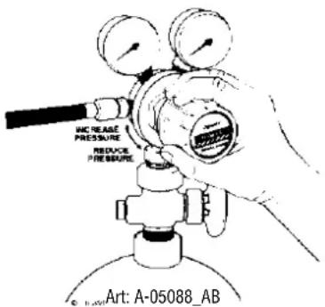
Figure 5-2: Adjust Flow Rate
With the regulator/flowmeter ready for operation, adjust working flow rate as follows:
- Slowly turn adjusting screw/knob in (clockwise) direction until the outlet gauge indicates the required flow rate.

NOTE 5
It may be necessary to re-check the shielding gas regulator/flowmeter flow rate following the first weld sequence due to back pressure present within shielding gas hose assembly..
- To reduce flow rate, allow the welding grade shielding gas to discharge from regulator/flowmeter by opening the downstream valve. Bleed welding grade shielding gas into a well ventilated area and away from any ignition source. Turn adjusting screw counterclockwise, until the required flow rate is indicated on the gauge. Close downstream valve.
Shutdown
Close cylinder valve whenever the regulator/flowmeter is not in use. To shut down for extended periods (more than 30 minutes).
- Close cylinder or upstream valve tightly.
- Open downstream equipment valves to drain the lines. Bleed gas into a well ventilated area and away from any ignition source.
- After gas is drained completely, disengage adjusting screw and close downstream equipment valves.
- Before transporting cylinders that are not secured on a cart designed for such purposes, remove regulators/flowmeters.
5.02 Attaching the MIG Torch (Euro)
Fit the MIG Torch to the power source by pushing the MIG torch connector into the MIG torch adaptor and screwing the plastic torch nut clockwise to secure the MIG torch to the MIG torch adaptor.
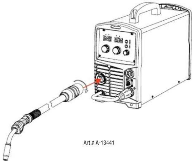
Figure 5-3: Attaching MIG Torch
5.03 Installing Minispool (100mm diameter)
As delivered from the factory, the unit is fitted with a Wire Spool Hub which accepts a Handispools of 200mm diameter.
In order to fit a Minispool (100mm diameter) assemble parts in the sequence shown below in Figure 5-4.
The nut and spring tighten the brake. The brake is correctly adjusted when the spool stops within 10 to 20mm (measured at the outer edge of the spool) after Mig Torch trigger is released. Wire should be slack without becoming dislodged from the spool.

CAUTION
Overtension of brake will cause rapid wear of mechanical WIREFEED parts, overheating of electrical componentry and possibly an increased incidence of wire Burnback into contact tip.
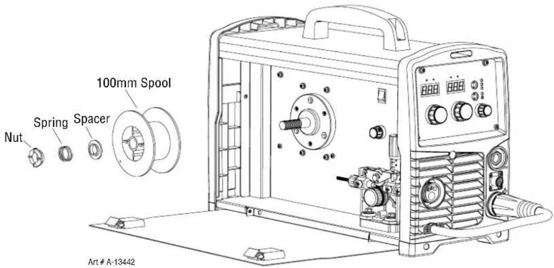
Figure 5-4: 100mm Spool Installation
5.04 Installing Handispool (200mm diameter)
As delivered from the factory, the unit is set for a Handispool (200mm diameter).
In order to re-fit a 200mm spool assemble parts in the sequence shown below in Figure 5-5.
Adjustment of the nut will control the Mig Wire Spool Brake. Clockwise rotation of this nut tightens the brake. The Brake is correctly adjusted when the spool stops within 10 to 20mm (measured at the outer edge of the spool) after Mig Torch trigger is released. Wire should be slack without becoming dislodged from the spool.

CAUTION
Overtension of brake will cause rapid wear of mechanical WIREFEED parts, overheating of electrical componentry and possibly an increased incidence of wire Burnback into contact tip.
Ensure that the alignment pin on the wire spool hub aligns with the hole allocated in the Handispool.

NOTE
This spool hub nut can be removed by unscrewing in an anticlockwise direction and locating in the appropriate position.
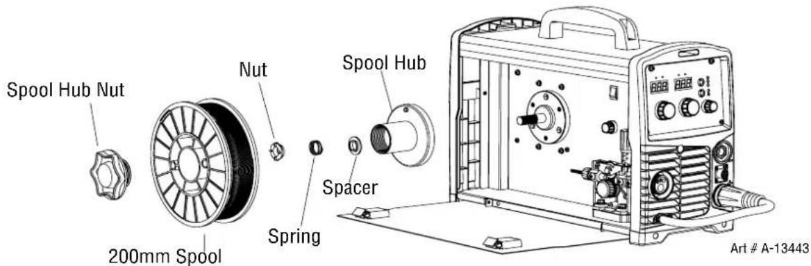
Figure 5-5: 200mm Handispool Installation
5.05 Inserting Wire into the Wire Feed Mechanism
Release the tension from the pressure roller by turning the adjustable wire drive tension screw in an anticlockwise direction. Then to release the pressure roller arm pull the pressure roller arm tension screw forward to release the pressure roller arm (Figure 5-6). With the MIG welding wire feeding from the bottom of the spool (Figure 5-7) pass the wire through the inlet guide, between the rollers, through the outlet guide and into the MIG torch. Re-secure the pressure roller arm and wire drive tension screw and adjust the pressure accordingly (Figure 5-6). Remove the contact tip from the MIG torch. With the MIG Torch lead reasonably straight, feed the wire through the torch by depressing the trigger switch. Fit the appropriate contact tip.
WARNING
Before connecting the work clamp to the work piece make sure the mains power supply is switched off. The wire will be at welding voltage potential while it is being feed through the system. Keep Mig Torch away from eyes and face.
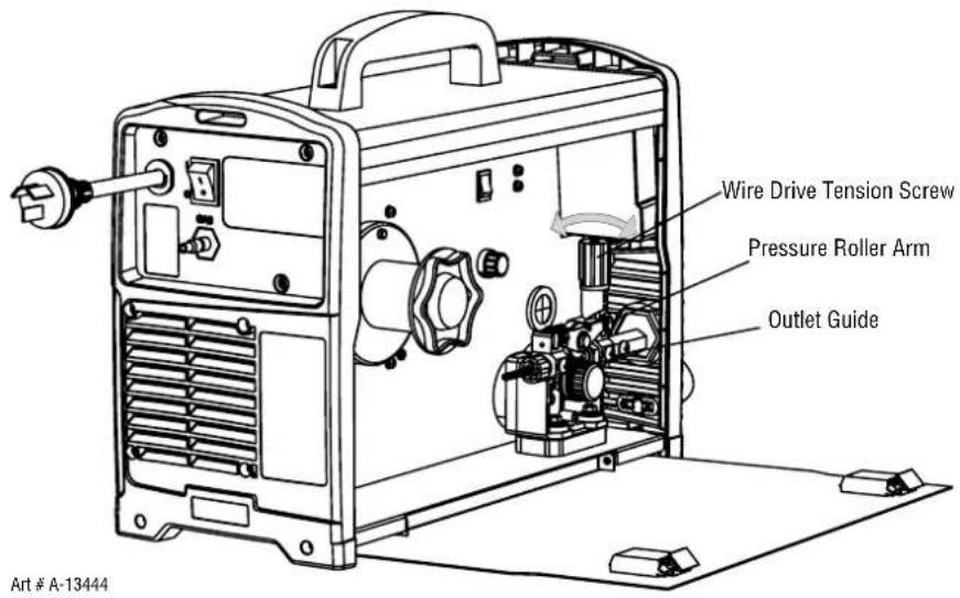
Figure 5-6: Wire Drive Assembly Components
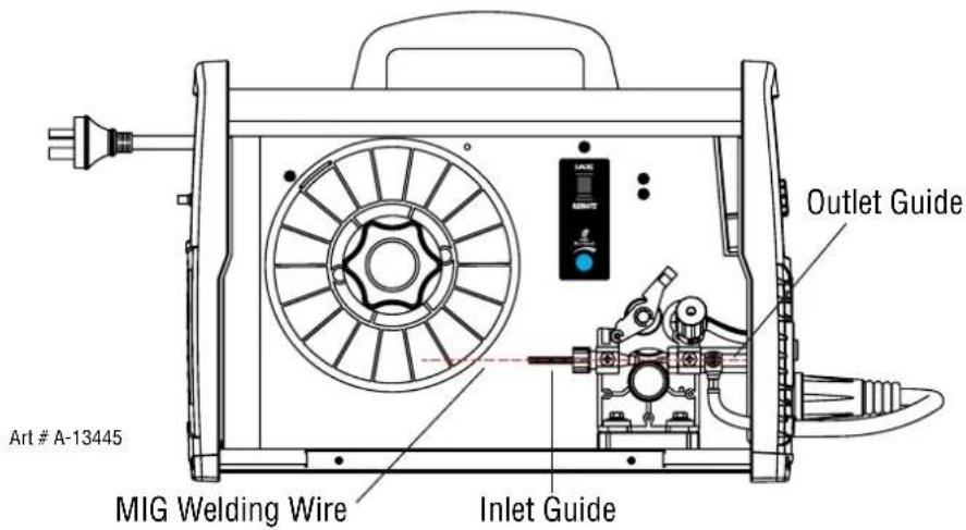
Figure 5-7: Mig Welding Wire - Installation
5.06 Feed Roller Pressure Adjustment
The pressure (top) roller applies pressure to the grooved feed roller via an adjustable pressure screw. These devices should be adjusted to a minimum pressure that will provide satisfactory WIREFEED without slippage. If slipping occurs, and inspection of the wire contact tip reveals no wear, distortion or burn back jam, the conduit liner should be checked for kinks and clogging by metal flakes and swarf. If it is not the cause of slipping, the feed roll pressure can be increased by rotating the pressure screw clockwise.

WARNING
Before changing the feed roller ensure that the mains supply to the power source is switched off..

CAUTION
The use of excessive pressure may cause rapid wear of the feed rollers, shafts and bearing.
5.07 Changing the Feed Roll
To change feed roll remove the feed roll retaining screw by turning in an anticlockwise direction. Once the feed roll is removed then to replace feed roll simply reverse these directions.
A dual groove feed roller is fitted as standard. It can accommodate 0.8/0.9mm Gasless Flux Cored Wires. Select the roller required with the chosen wire size marking facing outward.
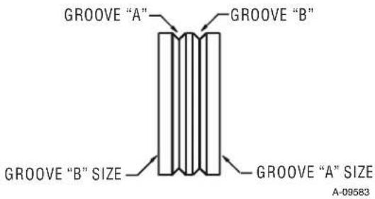
Figure 5-8: Dual Groove Feed Roller
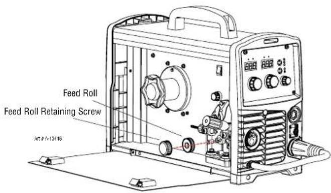
Figure 5-9: Changing the Feed Roll
5.08 Wire Reel Brake
The wire reel hub incorporates a friction brake which is adjusted during manufacture for optimum breaking. If it is considered necessary, adjustment can be made by turning the large nut inside the open end of the hub clockwise to tighten the brake. Correct adjustment will result in the wire reel circumference continuing no further than 10-20mm after release of the trigger. The wire should be slack without becoming dislodged from wire spool.

CAUTION
Overtension of brake will cause rapid wear of mechanical WIREFEED parts, overheating of electrical componentry and possibly an increased incidence of electrode wire Burnback into contact tip.
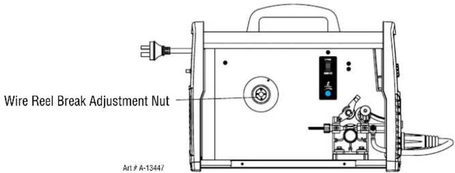
Figure 5-10: Wire Reel Brake
5.09 Setup for MIG (GMAW) Welding with Gas Shielded Mig Wire
A. Fit the MIG Torch to the Power Source. (Refer to section 5.02 Attaching the MIG Torch).
B. Connect the Mig torch polarity lead to the positive welding terminal (+). If in doubt, consult the wire manufacturer. Welding current flows from the Power Source via Dinse terminals. It is essential, however, that the male plug is inserted and turned securely to achieve a sound electrical connection.
C. Switch the Power Source On/Off switch located on the rear of the Power Source to the On position and ensure the Power indicator on the Front Panel is illuminated. Set the MIG Torch trigger switch operation either 2T or 4T mode (WeldSkill 185 only). Refer to section 4.02.2.
D. Select MIG mode with the process selection control. (refer to Section 4.02.1 for further information).
E. Fit the correct Feed Roll for the Gas Shielded MIG wire being used. Refer to section 2.11 Options and Accessories for Feed Roll types and Part Numbers
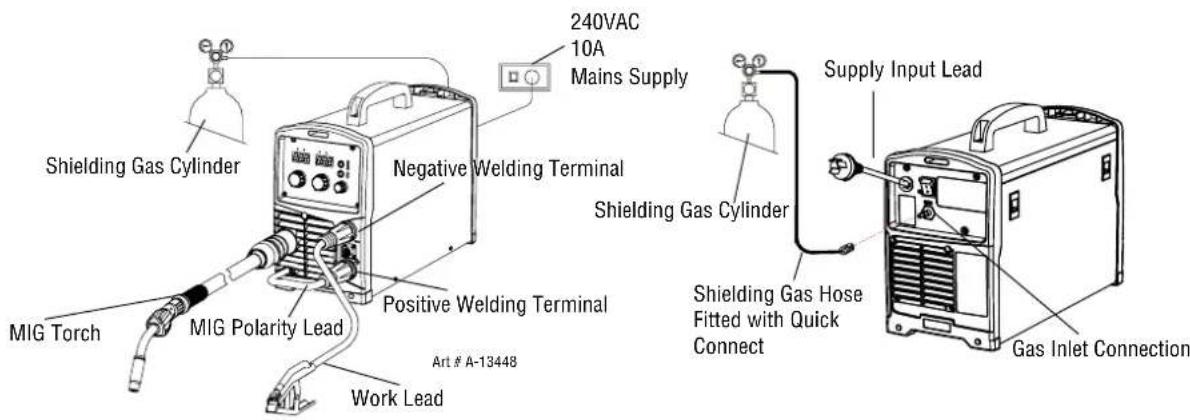
Figure 5-11: Setup for Mig Welding with Gas Shielded Mig Wire
F. Place the MIG wire spool onto the spool holder. Refer to sections 5.03 for 100mm diameter spools or 5.04 for 200mm diameter spools.
G. Feed wire through the wire drive mechanism. Refer to section 5.05.
H. Connect the work lead to the negative welding terminal (-). If in doubt, consult the wire manufacturer. Welding current flows from the Power Source via Dinse terminals. It is essential, however, that the male plug is inserted and turned securely to achieve a sound electrical connection.
I. Fit the welding grade shielding gas regulator/flowmeter to the shielding gas cylinder (refer to Section 5.01) then connect the shielding gas hose from the shielding gas regulator/flowmeter outlet to the quick connect Shielding Gas Inlet fitting gas on the rear of the WeldSkill 155 or WeldSkill 185 Power Source. Ensure that the shielding gas hose connection is sufficiently tight at the regulator connection and the quick connect fitting "locks" into place correctly on the rear of the power source.
J. As a guide for the welding parameter settings for the welding job refer to the Weld Guide located on the inside of the wirefeed compartment door. Power Source settings are adjusted using the front panel controls. Refer to section 4.02.
WARNING
Before connecting the work clamp to the work piece make sure the mains power supply is switched off..
WARNING
Secure the welding grade shielding gas cylinder in an upright position by chaining it to a suitable stationary support to prevent falling or tipping..

CAUTION
Loose welding terminal connections can cause overheating and result in the male plug being fused in the terminal. Remove any packaging material prior to use. Do not block the air vents at the front or rear of the Welding Power Source.
5.10 Setup for MIG (GMAW) Welding with Gasless MIG Wire (Flux Cored)
A. Fit the MIG Torch to the Power Source. (Refer to section 5.02 Attaching the MIG Torch).
B. Connect the Mig Torch polarity lead to the negative welding terminal (-). If in doubt, consult the wire manufacturer. Welding current flows from the power source via Dinse terminals. It is essential, however, that the male plug is inserted and turned securely to achieve a sound electrical connection.
C. Switch the Power Source On/Off switch (refer 4.02.18) located on the rear of the Power Source to the On position and ensure the Power indicator on the Front Panel is illuminated. Set the MIG Torch trigger switch operation either 2T ot 4T mode (WeldSkill 185 only). Refer to section 4.02.2.
D. Select MIG mode with the process selection control (refer to Section 4.02.1 for further information).
E. Fit the correct V Knurled Feed Roll for the Gasless MIG wire being used. Refer to section 2.11 Options and Accessories for Feed Roll types and Part Numbers
F. Place the MIG wire spool onto the spool holder. Refer to sections 5.03 for 100mm diameter spools or 5.04 for 200mm diameter spools.
G. Feed wire through the wire drive mechanism. Refer to section 5.05.
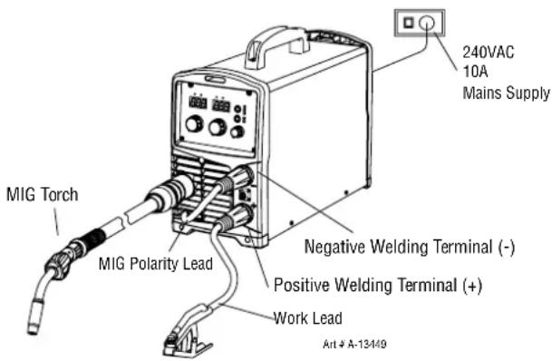
Figure 5-12: Setup for Mig Welding with Gasless Mig Wire
H. Connect the work lead to the positive welding terminal (+). If in doubt, consult the wire manufacturer. Welding current flows from the power source via Dinse terminals. It is essential, however, that the male plug is inserted and turned securely to achieve a sound electrical connection.
I. As a guide for the welding parameter settings for the welding job refer to the Weld Guide located on the inside of the wirefeed compartment door. Power Source settings are adjusted using the front panel controls. Refer to section 4.02.
WARNING
Before connecting the work clamp to the work piece make sure the mains power supply is switched off..

CAUTION
Loose welding terminal connections can cause overheating and result in the male plug being fused in the terminal. Remove any packaging material prior to use. Do not block the air vents at the front or rear of the Welding Power Source.
5.11 Setup for SPOOL GUN MIG (GMAW) Welding with Gas Shielded Mig Wire (WeldSkill 185 Only)
A. Select MIG mode with the process selection control (refer to Section 4.02.01 for further information).
B. Connect the Mig torch polarity lead to the positive welding terminal (+). If in doubt, consult the wire manufacturer. Welding current flows from the Power Source via Dinse type terminals. It is essential, however, that the male plug is inserted and turned securely to achieve a sound electrical connection.
C. Fit the Euro Spool Gun to the power source using the front panel EURO torch adaptor (refer also to section 5.02 Attaching the Mig Gun). Connect the 8 pin Remote Control Plug to the 8 pin Remote Control Socket on the power source. Ensure 8 pin plug is correctly fitted to the 8 pin socket on front panel and collar on plug is tightened firmly.
D. Connect the work lead to the negative welding terminal (-). If in doubt, consult the wire manufacturer. Welding current flows from the Power Source via Dinse type terminals. It is essential, however, that the male plug is inserted and turned securely to achieve a sound electrical connection.
E. Fit the welding grade shielding gas regulator/flowmeter to the shielding gas cylinder (refer to Section 5.01) then connect the shielding gas hose from the shielding gas regulator/flowmeter outlet to the quick connect Shielding Gas Inlet fitting gas on the rear of the WeldSkill 185 Power Source. Ensure that the shielding gas hose connection is sufficiently tight at the regulator connection and the quick connect fitting "locks" into place correctly on the rear of the power source.
F. Refer to the Weld Guide located on the inside of the wirefeed compartment door for further information.
G. Select MIG mode with the process selection control (refer to section 4.02.01 for further information).
H. Set the Local/Remote Switch located inside the wire drive compartment, to Remote.
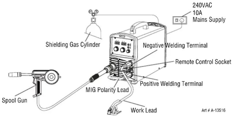
Figure 5-13: Setup for Spool Gun Welding with Gas Shielded Mig Wire with WeldSkill 185
WARNING
Before connecting the work clamp to the work piece make sure the mains power supply is switched off.
Secure the welding grade shielding gas cylinder in an upright position by chaining it to a suitable stationary support to prevent falling or tipping.

CAUTION
Loose welding terminal connections can cause overheating and result in the male plug being fused in the terminal.
Remove any packaging material prior to use. Do not block the air vents at the front or rear of the Welding Power Source.
5.12 MIG (GMAW/FCAW) Basic Welding Technique
Two different welding processes are covered in this section (GMAW and FCAW), with the intention of providing the very basic concepts in using the Mig mode of welding, where a welding gun is hand held, and the electrode (welding wire) is fed into a weld puddle, and the arc is shielded by an inert welding grade shielding gas or inert welding grade shielding gas mixture.
GAS METAL ARC WELDING (GMAW): This process, also known as MIG welding, CO_2 welding, Micro Wire Welding, short arc welding, dip transfer welding, wire welding etc., is an electric arc welding process which fuses together the parts to be welded by heating them with an arc between a solid continuous, consumable electrode and the work. Shielding is obtained from an externally supplied welding grade shielding gas or welding grade shielding gas mixture. The process is normally applied semi automatically; however the process may be operated automatically and can be machine operated. The process can be used to weld thin and fairly thick steels, and some non-ferrous metals in all positions.
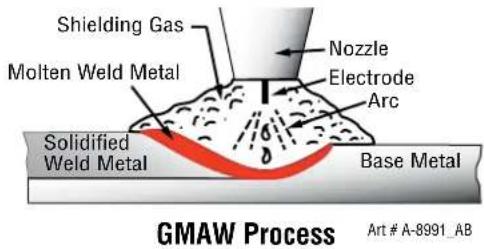
Figure 5-14
FLUX CORED ARC WELDING (FCAW): This is an electric arc welding process which fuses together the parts to be welded by heating them with an arc between a continuous flux filled electrode wire and the work. Shielding is obtained through decomposition of the flux within the tubular wire. Additional shielding may or may not be obtained from an externally supplied gas or gas mixture. The process is normally applied semi automatically; however the process may be applied automatically or by machine. It is commonly used to weld large diameter electrodes in the flat and horizontal position and small electrode diameters in all positions. The process is used to a lesser degree for welding stainless steel and for overlay work.
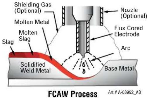
Figure 5-15
Position of MIG Torch
The angle of MIG torch to the weld has an effect on the width of the weld.
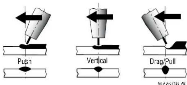
Figure 5-16
The welding gun should be held at an angle to the weld joint. (see Secondary Adjustment Variables below)
Hold the gun so that the welding seam is viewed at all times. Always wear the welding helmet with proper filter lenses and use the proper safety equipment.

CAUTION
Do not pull the welding gun back when the arc is established. This will create excessive wire extension (stick-out) and make a very poor weld.
The electrode wire is not energized until the gun trigger switch is depressed. The wire may therefore be placed on the seam or joint prior to lowering the helmet.
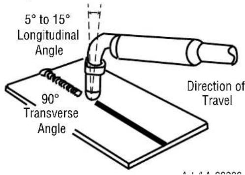
Figure 5-17
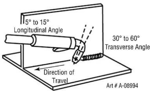
Figure 5-18
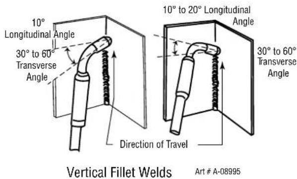
Figure 5-19
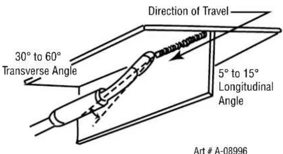
Figure 5-20
Distance from the MIG Torch Nozzle to the Work Piece
The electrode wire stick out from the MIG Torch nozzle should be between 10mm to 20.0mm. This distance may vary depending on the type of joint that is being welded.
Travel Speed
The speed at which the molten pool travels influences the width of the weld and penetration of the welding run.
MIG Welding (GMAW) Variables
Most of the welding done by all processes is on carbon steel. The items below describe the welding variables in short-arc welding of 24gauge (0.024", 0.6mm) to 14 " (6.4mm) mild sheet or plate. The applied techniques and end results in the GMAW process are controlled by these variables.
Preselected Variables
Preselected variables depend upon the type of material being welded, the thickness of the material, the welding position, the deposition rate and the mechanical properties. These variables are:
- Type of electrode wire
- Size of electrode wire
- Type of gas (not applicable to self shielding wires FCAW)
• Gas flow rate (not applicable to self shielding wires FCAW)
Primary Adjustable Variables
These control the process after preselected variables have been found. They control the penetration, bead width, bead height, arc stability, deposition rate and weld soundness. They are:
- Arc Voltage
• Welding current (wire feed speed) - Travel speed
Secondary Adjustable Variables
These variables cause changes in primary adjustable variables which in turn cause the desired change in the bead formation. They are:
- Stick-out (distance between the end of the contact tube (tip) and the end of the electrode wire). Maintain at about 10mm stick-out.
- Wire Feed Speed. Increase in wire feed speed increases weld current, Decrease in wire feed speed decreases weld current.
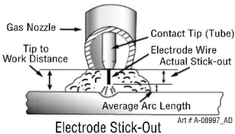
Figure 5-21
- Nozzle Angle. This refers to the position of the welding gun in relation to the joint. The transverse angle is usually one half the included angle between plates forming the joint. The longitudinal angle is the angle between the centre line of the welding gun and a line perpendicular to the axis of the weld. The longitudinal angle is generally called the Nozzle Angle and can be either trailing (pulling) or leading (pushing). Whether the operator is left handed or right handed has to be considered to realize the effects of each angle in relation to the direction of travel.
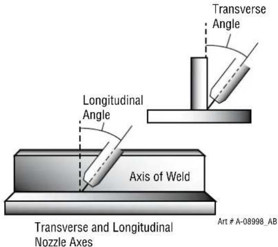
Figure 5-22
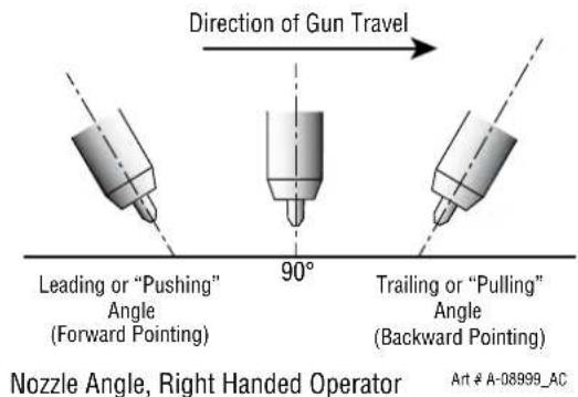
Figure 5-23
Establishing the Arc and Making Weld Beads
Before attempting to weld on a finished piece of work, it is recommended that practice welds be made on a sample metal of the same material as that of the finished piece.
The easiest welding procedure for the beginner to experiment with MIG welding is the flat position. The equipment is capable of flat, vertical and overhead positions.
For practicing MIG welding, secure some pieces of 16 or 18 gauge (0.06" 1.5mm or 0.08" 2.0mm) mild steel plate 6" x 6" (150 x 150mm). Use 0.030" (0.8mm) flux cored gasless wire or a solid wire with shielding gas.
Setting of the Power Source
Power source and Wirefeeder setting requires some practice by the operator, as the welding plant has two control settings that have to balance. These are the Wirespeed control (refer to section 4.02.06) and the welding Voltage Control (refer to section 4.02.07). The welding current is determined by the Wirespeed control, the current will increase with increased Wirespeed, resulting in a shorter arc. Less wire speed will reduce the current and lengthen the arc. Increasing the welding voltage hardly alters the current level, but lengthens the arc. By decreasing the voltage, a shorter arc is obtained with a little change in current level.
When changing to a different electrode wire diameter, different control settings are required. A thinner electrode wire needs more Wirespeed to achieve the same current level.
A satisfactory weld cannot be obtained if the Wirespeed and Voltage settings are not adjusted to suit the electrode wire diameter and the dimensions of the work piece.
If the Wirespeed is too high for the welding voltage, “stubbing” will occur as the wire dips into the molten pool and does not melt. Welding in these conditions normally produces a poor weld due to lack of fusion. If, however, the welding voltage is too high, large drops will form on the end of the wire, causing spatter. The correct setting of voltage and Wirespeed can be seen in the shape of the weld deposit and heard by a smooth regular arc sound. Refer to the Weld Guide located on the inside of the wirefeed compartment door for setup information.
Electrode Wire Size Selection
The choice of Electrode wire size and shielding gas used depends on the following
• Thickness of the metal to be welded
- Type of joint
- Capacity of the wire feed unit and Power Source
• The amount of penetration required
• The deposition rate required
- The bead profile desired
• The position of welding
- Cost of the wire
5.13 CIGWELD MIG Wire Selection Chart
WeldSkill 155/185
WELDING WIRE SELECTION CHART
| DESCRIPTION DIAMETER PACK PART NUMBER APPLICATION | ||||
| WELDSKILL SOLID WELDING WIRE | 0.6mm Minispool 0.9kg WS0906 | General purpose welding wire suitable for the all positional Gas Metal Arc Welding (GWAW) of mild and low alloy steels, used in general fabrication and for welding of light to medium gauge sheet and tubular steel sections. Note that a suitable shielding gas is required. | ||
| 0.6mm Handispool 5kg WS5006 | ||||
| 0.8mm Minispool 0.9kg WS0908 | ||||
| 0.8mm Handispool 5kg WS5008 | ||||
| 0.9mm Minispool 0.9kg WS0909 | ||||
| 0.9mm Handispool 5kg WS5009 | ||||
| WELDSKILL GASLESS WELDING WIRE | 0.8mm Minispool 0.9kg WG0908 | WeldSkill Gasless wire is an all positional self-shielded flux cored wire recommended for single pass welding applications only. It is excellent for single-pass lap, fillet and butt welding of thin gauged galvanised and mild steels. | ||
| 0.8mm Handispool 4.5kg WG4508 | ||||
| 0.9mm Minispool 0.9kg WG0909 | ||||
| 0.9mm Handispool 4.5kg WG4509 | ||||
| AUTOCRAFT 316LSI SOLID STAINLESS STEEL MIG WIRE | 0.8mm Minispool 1kg 721285 | General purpose all positional stainless steel wire providing excellent results when used with correct shielding gas. Suitable for the general welding of a wide range of stainless steels (300 & 400 series). | ||
| 0.8mm Handispool 5kg | 720288 | |||
| 0.9mm Handispool 5kg | 720283 | |||
| AUTOCRAFT AL5356 SOLID ALUMINIUM MIG WIRE | 0.9mm Minispool 0.5kg | 721223 | Excellent general purpose Aluminium MIG wire suitable for the welding of a wide range of wrought and cast Aluminium alloys containing Magnesium. Note that a suitable shielding gas is required. | |
| 1.0mm Minispool 0.5kg | 721224 | |||
| 1.0mm Handispool 2kg | 723224 | |||
| AUTOCRAFT SILICON BRONZE MIG WIRE | 0.8mm Handispool 5kg | 720159 | Used for lower strength welding of steels in automotive applications. It can also be used for welding copper-silicon alloys in hot water systems, heat exchangers and marine components. | |
NOTE: MINISPOOL = 100MM DIAMETER, HANDISPOOL = 200MM DIAMETER
Table 5-1: Cigweld MIG Wire Selection Chart
5.14 MIG (GMAW/FCAW) Welding Troubleshooting
Solving Problems Beyond the Welding Terminals
The general approach to fix Gas Metal Arc Welding (GMAW) problems is to start at the wire spool then work through to the MIG torch. There are two main areas where problems occur with GMAW, Porosity and Inconsistent wire feed
Solving Problems Beyond the Welding Terminals - Porosity
When there is a gas problem the result is usually porosity within the weld metal. Porosity always stems from some contaminant within the molten weld pool which is in the process of escaping during solidification of the molten metal. Contaminants range from no gas around the welding arc to dirt on the work piece surface. Porosity can be reduced by checking the following points.
| FAULT CAUSE | |
| 1 Shielding gas cylinder contents and flow meter. | Ensure that the shielding gas cylinder is not empty and the flow meter is correctly adjusted to 15 litres per minute. |
| 2 Gas leaks. Check for gas leaks between the regulator/cylinder connection and in the gas hose to the Power Source. | |
| 3 Internal gas hose in the Power Source. | Ensure the hose from the solenoid valve to the torch adaptor has not fractured and that it is connected to the torch adaptor. |
| 4 Welding in a windy environment. Shield the weld area from the wind or increase the gas flow. | |
| 5 Welding dirty, oily, painted, oxidised or greasy plate. | Clean contaminates off the work piece. |
| 6 Distance between the MIG torch nozzle and the work piece. | Keep the distance between the MIG torch nozzle and the work piece to a minimum. Refer to section 5.11 |
| 7 Maintain the MIG torch in good working order. | A Ensure that the gas holes are not blocked and gas is exiting out of the torch nozzle.B Do not restrict gas flow by allowing spatter to build up inside the torch nozzle.C Check that the MIG torch O-rings are not damaged. |
Table 5-2: Solving Problems beyond the Welding Terminals-Porosity
WARNING
Disengage the feed roll when testing for gas flow by ear..
Solving Problems Beyond the Welding Terminals - Inconsistent Wire Feed
Wire feeding problems can be reduced by checking the following points.
| FAULT CAUSE | |
| 1 Feed roller driven by motor in the wirefeed compartment slipping. | A Wire spool brake is too tight. (Refer 5.08). |
| B Incorrect feed roll fitted for wire used. Check and change to correct feed roll if necessary. (Refer options and accessories table 2.11 for feed roll options) | |
| 2 Wire spool unwinded and tangled. Wire spool brake is too loose. (Refer 5.08) | |
| 3 Worn or incorrect feed roller size A Use a feed roller matched to the size you are welding.B Replace feed roller if worn. | |
| 4 Wire rubbed against the mis-aligned guides and reduced wire feedability. | Mis-alignment of inlet/outlet guides |
| 5 Liner blocked with swarf A Increased amounts of swarf are produced by the wire passing through the feed roller when excessive pressure is applied to the pressure roller adjuster.B Swarf can also be produced by the wire passing through an incorrect feed roller groove shape or size.C Swarf is fed into the conduit liner where it accumulates thus reducing wire feedability. | |
| 6 Incorrect or worn contact tip A The contact tip transfers the weld current to the electrode wire. If the hole in the contact tip is too large then arcing may occur inside the contact tip resulting in the wire jamming in the contact tipB When using soft wire such as aluminium it may become jammed in the contact tip due to expansion of the wire when heated. A contact tip designed for soft wires should be used. | |
| 7 Poor work lead contact to work piece If the work lead has a poor electrical contact to the work piece then the connection point will heat up and result in a reduction of power at the arc. | |
| 8 Bent liner This will cause friction between the wire and the liner thus reducing wire feedability | |
Table 5-3: Wire Feeding Problems
Basic MIG (GMAW) Welding Troubleshooting
| FAULT CAUSE | REMEDY | |
| 1 Undercut A Welding arc voltage too high.B Incorrect torch angle B Adjust angle.C Excessive heat input C Increase the torch travel speed and/or decrease welding current by decreasing the voltage or decreasing the wire feed speed. | A Decrease voltage or increase the wire feed speed. | |
| 2 Lack of penetration | A Welding current too lowB Joint preparation too narrow or gap too tightC Shielding gas incorrect C Change to a gas which gives higher penetration. | A Increase welding current by increasing wire feed speed and increasing voltage.B Increase joint angle or gap. |
| 3 Lack of fusion Voltage too low Increase voltage. | ||
| 4 Excessive spatter A Voltage too high A Decrease voltage or increase the wirespeed control.B Voltage too low B Increase the voltage or decrease wirespeed. | ||
| 5 Irregular weld shape | A Incorrect voltage and current settings.Convex, voltage too low.Concave, voltage too high.B Wire is wandering.C Incorrect shielding gas D Insufficient or excessive heat input | A Adjust voltage and current by adjusting the voltage control and the wirespeed control.B Replace contact tip.C Check shielding gas.D Adjust the wirespeed control or the voltage control. |
| 6 Weld cracking | A Weld beads too small A Decrease travel speedB Weld penetration narrow and deepC Excessive weld stresses D Increase weld metal strength or revise designD Excessive voltageE Cooling rate too fastD Decrease voltage.E Slow the cooling rate by preheating part to be welded or cool slowly. | |
| 7 Cold weld puddle | A Loose welding cable connection.B Low primary voltageC Fault in power source CHave an Accredited CIGWELD Service Provider to test then replace the faulty component. | A Check all welding cable connections.B Contact supply authority. |
| 8 Arc does not have a crisp sound that short arc exhibits when the wirefeed speed and voltage are adjusted correctly. | The MIG torch has been connected to the wrong voltage polarity on the front panel. | Connect the MIG torch to the positive (+) welding terminal for most solid wires and gas shielded flux cored wires. Connect MIG Torch to the negative (-) welding terminal for most Gasless Wires. Refer to the electrode wire manufacturer for the correct polarity. |
Table 5-4: MIG (GMAW) Welding Problems
SECTION 6:
STICK (MMAW) WELDING
6.01 Setup For STICK (MMAW) Welding
A. Select Stick mode with the process selection control (refer to Section 4.02.01 for further information).
B. Connect the Electrode Holder lead to the positive welding terminal (+). If in doubt, consult the electrode manufacturer. Welding current flows from the Power Source via Dinse type terminals. It is essential, however, that the male plug is inserted and turned securely to achieve a sound electrical connection.
C. Connect the work lead to the negative welding terminal (-). If in doubt, consult the electrode manufacturer. Welding current flows from the power source via Dinse type terminals. It is essential, however, that the male plug is inserted and turned securely to achieve a sound electrical connection.
WARNING
Before connecting the work clamp to the work and inserting the electrode in the electrode holder make sure the Mains power supply is switched off.
CAUTION
Remove any packaging material prior to use. Do not block the air vents at the front or rear of the Welding Power Source.

NOTE!
Consult the electrode manufacturer's information for the correct polarity.
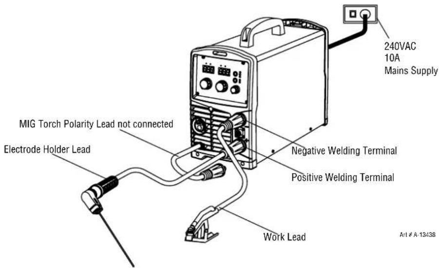
Figure 6-1: Setup For STICK (MMAW) Welding
6.02 Arc Welding Electrodes
Metal arc welding electrodes consist of a core wire surrounded by a flux coating. The flux coating is applied to the core wire by an extrusion process.
The coating on arc welding electrodes serves a number of purposes:
A. To provide a gaseous shield for the weld metal, and preserve it from contamination by the atmosphere whilst in a molten state.
B. To give a steady arc by having ‘arc stabilisers’ present, which provide a bridge for current to flow across.
C. To remove oxygen from the weld metal with 'deoxidisers'.
D. To provide a cleansing action on the work piece and a protective slag cover over the weld metal to prevent the formation of oxides while the metal is solidifying. The slag also helps to produce a bead of the desired contour.
E. To introduce alloys into the weld deposits in special type electrodes.
6.03 Types of Electrodes
Arc Welding electrodes are classified into a number of groups depending on their applications. There are a great number of electrodes used for specialised industrial purposes which are not of particular interest for everyday general work. These include some low hydrogen types for high tensile steel, cellulose types for welding large diameter pipes, etc.
The range of electrodes dealt with in this publication will cover the vast majority of applications likely to be encountered; are all easy to use and all will work on even the most basic of welding machines.
| CIGWELD Electrode Selection Chart | ||||
| Description Diameter Pack Part No. Application | ||||
| Satincraft 13 | 2.5mm | 1kg | 322135 | General purpose electrode suitable for all positional welding and galvanised steel. |
| 2.5mm | 2.5kg | 612182 | ||
| 3.2mm | 1kg | 322136 | ||
| 3.2mm | 2.5kg | 612183 | ||
| 4.0mm | 5kg | 611184 | ||
| Ferrocraft 12XP | 2.0mm | 1kg | 322128 | General purpose, extra performance electrode recommended for all positional (inc. Vertical down) welding of mild and galvanised steel. |
| 2.0mm | 2.5kg | 612231 | ||
| 2.5mm | 1kg | 322129 | ||
| 2.5mm | 2.5kg | 612232 | ||
| 3.2mm | 1kg | 322138 | ||
| 3.2mm | 2.5kg | 612233 | ||
| 4.0mm | 5kg | 611234 | ||
| WeldSkill GP | 2.0mm | 1 kg | WEG1020 | User-friendly GP electrode for welding thin section mild and galvanised steels. Excellent for vertical down fillet welding applications. |
| 2.0mm | 2.5 kg | WEG2520 | ||
| 2.5mm | 1 kg | WEG1025 | ||
| 2.5mm | 2.5 kg | WEG2525 | ||
| 2.5mm | 5 kg | WEG5025 | ||
| 3.2mm | 1 kg | WEG1032 | ||
| 3.2mm | 2.5 kg | WEG2532 | ||
| 3.2mm | 5 kg | WEG5032 | ||
| 4.0mm | 5 kg | WEG5040 | ||
| Spezial OK53.16 Twincoat | 2.5mm | 2 kg | 53162534G0 | Hydrogen Controlled type offering exceptional AC/DC performance in all welding positions. |
| 3.2mm | 1.6 kg | 53163234G0 | ||
| 4.0mm | 2.2 kg | 53164044G0 | ||
| Satincrome308L-17 | 2.5mm | 2.5 kg | 611602 | Stainless Steel type for 19Cr/10Ni stainless grades including 201, 202, 301, 302, 303, 304, 304L, 305, 308, etc |
| 3.2mm | 2.5 kg | 611603 | ||
| 4.0mm | 2.5 kg | 611604 | ||
| CIGWELD Electrode Selection Chart cont'd | ||||
| Description | Diameter Pack | Part No. | Application | |
| Satincrome 309Mo-17 | 2.5mm | 2.5 kg | 611692 | Stainless Steel type for 309 and 309L grades. It is also suitable for welding of dissimilar welding of other 300 series stainless steels. |
| 3.2mm | 2.5 kg | 611693 | ||
| 4.0mm | 2.5 kg | 611694 | ||
| Satincrome 316L-17 | 2.0mm | 2,5 kg | 611661 | Stainless Steel type for welding of matching Mo bearing grades, 316 and 316L. |
| 2.5mm | 2.5 kg | 611662 | ||
| 3.2mm | 2.5 kg | 611663 | ||
| 2.5/3.2mm | Blisterpack | 322215 | ||
| 4.0mm | 2.5 kg | 611664 | ||
| Weldall | 2.5mm | 2.5 kg | 611702 | High alloy stainless steel type for welding of unknown steels, repair of die or tool steels and for joining dissimilar steels. (Not recommended for cast iron). |
| 3.2mm | 2.5 kg | 611703 | ||
| 2.5/3.2mm | Blisterpack | 322216 | ||
| 4.0mm | 2.5 kg | 611704 | ||
| Castcraft 55 3 | 2mm 2.5 kg 611723 | For repair and maintenance welding of S.G. cast iron, meehanite and other cast irons. It produces a higher strength weld than Castcraft 100. | ||
| Castcraft 100 | 2.5mm | 2.5 kg | 611732 | Soft, Ductile Nickel type electrode for repair and maintenance welding of a wide range of cast irons. It has better “wetting” action than Castcraft 55. |
| 3.2mm | 2.5 kg | 611733 | ||
| Blisterpack | Blisterpack | 322217 | ||
| 4.0mm | 2.5 kg | 611734 | ||
Cigweld Electrode Selection Chart continued over page
Table 6-1 Types of Electrodes
6.04 Size of Electrode
The electrode size is determined by the thickness of metals being joined and can also be governed by the type of welding machine available. Small welding machines will only provide sufficient current (amperage) to run the smaller size electrodes.
For most work, a 2.5mm electrode will be quite sufficient. A 2.5mm electrode will give just as strong a joint but may require a few more weld runs to be put down to fill the joint.
For thin sections, it is necessary to use smaller electrodes otherwise the arc may burn holes through the job. A little practice will soon establish the most suitable electrode for a given application.
6.05 Storage of Electrodes
Always store electrodes in a dry place and in their original containers.
6.06 Electrode Polarity
Electrodes are connected to the Electrode Holder, and the Work Lead is connected to the work piece. Consult the Electrode manufacturer's information for the correct polarity.
6.07 Effects of Arc Welding Various Materials
A. High tensile and alloy steels
The two most prominent effects of welding these steels are the formation of a hardened zone in the weld area, and, if suitable precautions are not taken, the occurrence in this zone of under-bead cracks may result. Hardened zone and under-bead cracks in the weld area may be reduced by using the correct electrodes, preheating, using higher current settings, using larger electrodes sizes, short runs for larger electrode deposits or tempering in a furnace.
B. Austenitic manganese steels
The effect on manganese steel of slow cooling from high temperatures is to embrittle it. For this reason it is absolutely essential to keep manganese steel cool during welding by quenching after each weld or skip welding to distribute the heat.
C. Cast Iron
Most types of cast iron, except white iron, are weldable. White iron, because of its extreme brittleness, generally cracks when attempts are made to weld it. Trouble may also be experienced when welding white-heart malleable, due to the porosity caused by gas held in this type of iron.
D. Copper and alloys
The most important factor is the high rate of heat conductivity of copper, making preheating of heavy sections necessary to give proper fusion of weld and base metal.
6.08 Arc Welding Practice
The techniques used for arc welding are almost identical regardless of what types of metals are being joined. Naturally enough, different types of electrodes would be used for different metals as described in the preceding section.
6.09 Welding Position
The electrodes dealt with in this publication can be used in most positions, i.e. they are suitable for welding in flat, horizontal, vertical and overhead positions. Numerous applications call for welds to be made in positions intermediate between these. Some of the common types of welds are shown in Figures 6-2 through 6-9.
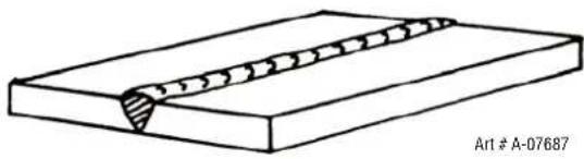
natural_image
Technical line drawing of a welded joint or weld (no text or symbols)Figure 6-2: Flat position, down hand butt weld
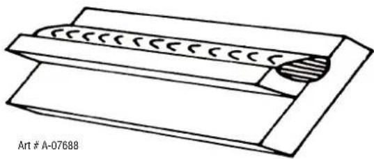
natural_image
Technical line drawing of a mechanical component with a circular feature and textured outer layer (no text or symbols)Figure 6-3: Flat position, gravity fillet weld
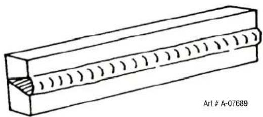
natural_image
Technical line drawing of a rectangular block with internal grooves and a notch, no text or symbols presentFigure 6-4: Horizontal position, butt weld
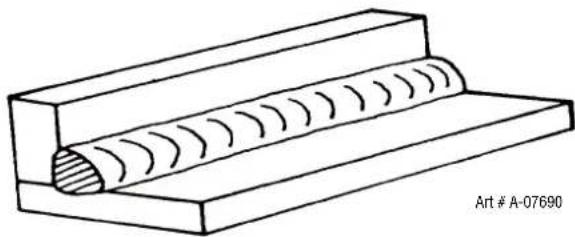
natural_image
Technical line drawing of a mechanical component with internal grooves and a base plate (no text or symbols)Figure 6-5: Horizontal - Vertical (HV) position
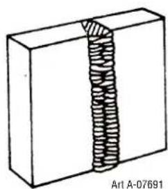
natural_image
Diagram of a coiled spring attached to a rectangular block, labeled Art A-07691 (no text or symbols on the diagram itself)Figure 6-6: Vertical position, butt weld
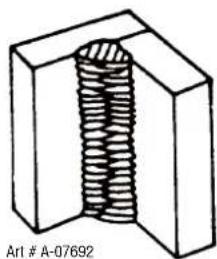
natural_image
Diagram of a solenoid inside a U-shaped block (no text or symbols)Figure 6-7: Vertical position, fillet weld
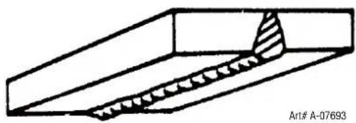
natural_image
Technical line drawing of a mechanical joint or bracket with hatched internal detail (no text or symbols)Figure 5-6: Overhead position, butt weld
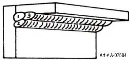
Figure 6-9: Overhead position fillet, weld
6.10 Joint Preparations
In many cases, it will be possible to weld steel sections without any special preparation. For heavier sections and for repair work on castings, etc., it will be necessary to cut or grind an angle between the pieces being joined to ensure proper penetration of the weld metal and to produce sound joints.
In general, surfaces being welded should be clean and free of rust, scale, dirt, grease, etc. Slag should be removed from oxy-cut surfaces. Typical joint designs are shown in Figure 6-10.
Open Square Butt
Joint
Gap varies from
1.6mm (1/16") to 4.8mm (3/16")
depending on plate thickness
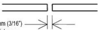
Single Vee Butt Joint
Not less than
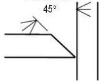
Lap Joint
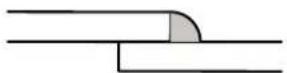
Fillet Joint
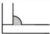
Corner Weld
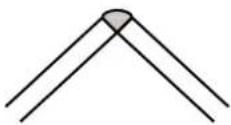
Single Vee Butt Joint
Not less than
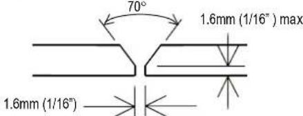
Not less than
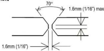
Tee Joints
(Fillet both sides of the joint)
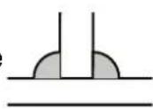
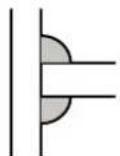
Edge Joint
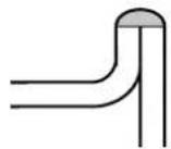
Art # A-07695_AE
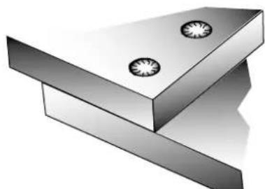
natural_image
3D rendering of a metallic L-shaped bracket with two circular holes on top (no text or symbols)Plug Weld Plug Weld
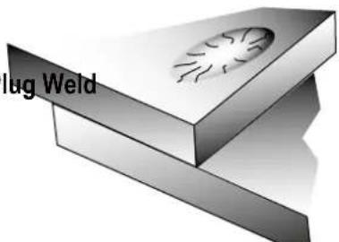
natural_image
3D illustration of a mechanical component with a curved surface and label 'lug Weld' (no other text or symbols)Figure 6-10: Typical joint designs for arc welding
6.11 Arc Welding Technique
A Word to Beginners
For those who have not yet done any welding, the simplest way to commence is to run beads on a piece of scrap plate. Use mild steel plate about 6.0mm thick and a 3.2mm electrode. Clean any paint, loose scale or grease off the plate and set it firmly on the work bench so that welding can be carried out in the downhand position. Make sure that the work clamp is making good electrical contact with the work, either directly or through the work table. For light gauge material, always clamp the work lead directly to the job, otherwise a poor circuit will probably result.
6.12 The Welder
Place yourself in a comfortable position before beginning to weld. Get a seat of suitable height and do as much work as possible sitting down. Don't hold your body tense. A taut attitude of mind and a tensed body will soon make you feel tired. Relax and you will find that the job becomes much easier. You can add much to your peace of mind by wearing a leather apron and gauntlets. You won't be worrying then about being burnt or sparks setting alight to your clothes.
Place the work so that the direction of welding is across, rather than to or from, your body. The electrode holder lead should be clear of any obstruction so that you can move your arm freely along as the electrode burns down. If the lead is slung over your shoulder, it allows greater freedom of movement and takes a lot of weight off your hand. Be sure the insulation on your cable and electrode holder is not faulty, otherwise you are risking an electric shock.
6.13 Striking the Arc
Practice this on a piece of scrap plate before going on to more exacting work. You may at first experience difficulty due to the tip of the electrode “sticking” to the work piece. This is caused by making too heavy a contact with the work and failing to withdraw the electrode quickly enough. A low amperage will accentuate it. This freezing-on of the tip may be overcome by scratching the electrode along the plate surface in the same way as a match is struck. As soon as the arc is established, maintain a 1.6mm to 3.2mm gap between the burning electrode end and the parent metal. Draw the electrode slowly along as it melts down.
Another difficulty you may meet is the tendency, after the arc is struck, to withdraw the electrode so far that the arc is broken again. A little practice will soon remedy both of these faults.
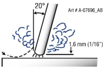
Figure 6-11: Striking an arc
6.14 Arc Length
The securing of an arc length necessary to produce a neat weld soon becomes almost automatic. You will find that a long arc produces more heat. A very long arc produces a crackling or spluttering noise and the weld metal comes across in large, irregular blobs. The weld bead is flattened and spatter increases. A short arc is essential if a high quality weld is to be obtained although if it is too short there is the danger of it being blanketed by slag and the electrode tip being solidified in. If this should happen, give the electrode a quick twist back over the weld to detach it. Contact or “touch-weld” electrodes such as Ferrocraft 21 do not stick in this way, and make welding much easier.
6.15 Rate of Travel
After the arc is struck, your next concern is to maintain it, and this requires moving the electrode tip towards the molten pool at the same rate as it is melting away. At the same time, the electrode has to move along the plate to form a bead. The electrode is directed at the weld pool at about 20^ from the vertical. The rate of travel has to be adjusted so that a well-formed bead is produced.
If the travel is too fast, the bead will be narrow and strung out and may even be broken up into individual globules. If the travel is too slow, the weld metal piles up and the bead will be too large.
6.16 Making Welded Joints
Having attained some skill in the handling of an electrode, you will be ready to go on to make up welded joints.

NOTE!
The welding current range values should be used as a guide only. Current delivered to the arc is dependent on the welding arc voltage, and as welding arc voltage varies between different classes of electrode, welding current at any one setting would vary according to the type of electrode in use. The operator should use the welding current range values as a guide, then finally adjust the current setting to suit the application.
A. Butt Welds
Set up two plates with their edges parallel, as shown in Figure 6-12, allowing 1.6mm to 2.4mm gap between them and tack weld at both ends. This is to prevent contraction stresses from the cooling weld metal pulling the plates out of alignment. Plates thicker than 6.0mm should have their mating edges bevelled to form a 70° to 90° included angle. This allows full penetration of the weld metal to the root. Using a 3.2mm Ferrocraft 21 electrode at 100 amps, deposit a run of weld metal on the bottom of the joint.
Do not weave the electrode, but maintain a steady rate of travel along the joint sufficient to produce a well-formed bead. At first you may notice a tendency for undercut to form, but keeping the arc length short, the angle of the electrode at about 20^ from vertical, and the rate of travel not too fast, will help eliminate this. The electrode needs to be moved along fast enough to prevent the slag pool from getting ahead of the arc. To complete the joint in thin plate, turn the job over, clean the slag out of the back and deposit a similar weld.
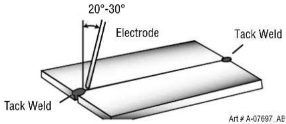
Figure 6-12: Butt weld
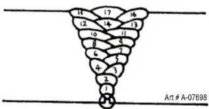
Figure 6-13: Weld build up sequence
Heavy plate will require several runs to complete the joint. After completing the first run, chip the slag out and clean the weld with a wire brush. It is important to do this to prevent slag being trapped by the second run. Subsequent runs are then deposited using either a weave technique or single beads laid down in the sequence shown in Figure 6-13. The width of weave should not be more than three times the core wire diameter of the electrode. When the joint is completely filled, the back is either machined, ground or gouged out to remove slag which may be trapped in the root, and to prepare a suitable joint for depositing the backing run. If a backing bar is used, it is not usually necessary to remove this, since it serves a similar purpose to the backing run in securing proper fusion at the root of the weld.
B. Fillet Welds
These are welds of approximately triangular cross-section made by depositing metal in the corner of two faces meeting at right angles. Refer to Figure 6-3.
A piece of angle iron is a suitable specimen with which to begin, or two lengths of strip steel may be tacked together at right angles. Using a 3.2mm Ferrocraft 21 electrode at 100 amps, position angle iron with one leg horizontal and the other vertical. This is known as a horizontal-vertical (HV) fillet. Strike the arc and immediately bring the electrode to a position perpendicular to the line of the fillet and about 45° from the vertical. Some electrodes require to be sloped about 20° away from the perpendicular position to prevent slag from running ahead of the weld. Refer to Figure 6-14. Do not attempt to build up much larger than 6.4mm width with a 3.2mm electrode, otherwise the weld metal tends to sag towards the base, and undercut forms on the vertical leg. Multi-runs can be made as shown in Figure 6-15. Weaving in HV fillet welds is undesirable.
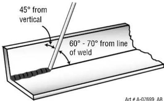
Figure 6-14: Electrode position for HV fillet weld
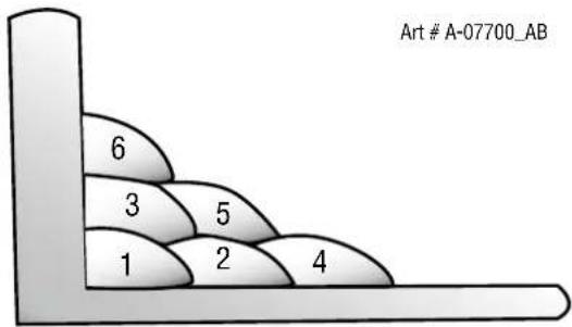
Figure 6-15: Multi-runs in HV fillet weld
C. Vertical Welds
1. Vertical Up
Tack weld a three feet length of angle iron to your work bench in an upright position. Use a 3.2mm Ferrocraft 21 electrode and set the current at 100 amps. Make yourself comfortable on a seat in front of the job and strike the arc in the corner of the fillet. The electrode needs to be about 10° from the horizontal to enable a good bead to be deposited. Refer Figure 6-16. Use a short arc, and do not attempt to weave on the first run. When the first run has been completed de-slag the weld deposit and begin the second run at the bottom. This time a slight weaving motion is necessary to cover the first run and obtain good fusion at the edges. At the completion of each side motion, pause for a moment to allow weld metal to build up at the edges, otherwise undercut will form and too much metal will accumulate in the centre of the weld. Figure 6-17 illustrates multi-run technique and Figure 5-18 shows the effects of pausing at the edge of weave and of weaving too rapidly.
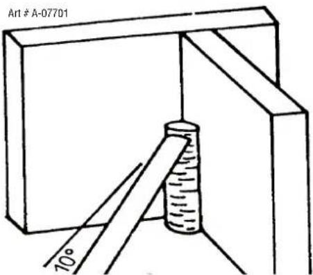
Figure 6-16: Single run vertical fillet weld
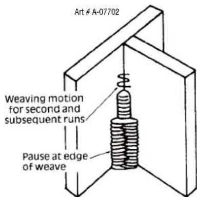
Figure 6-17: Multi run vertical fillet weld
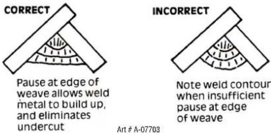
Figure 6-18: Examples of vertical fillet welds
2. Vertical Down
The Ferrocraft 21 electrode makes welding in this position particularly easy. Use a 3.2mm electrode at 100 amps. The tip of the electrode is held in light contact with the work and the speed of downward travel is regulated so that the tip of the electrode just keeps ahead of the slag. The electrode should point upwards at an angle of about 45°.
3. Overhead Welds
Apart from the rather awkward position necessary, overhead welding is not much more difficult that downhand welding. Set up a specimen for overhead welding by first tacking a length of angle iron at right angles to another piece of angle iron or a length of waste pipe. Then tack this to the work bench or hold in a vice so that the specimen is positioned in the overhead position as shown in the sketch. The electrode is held at 45° to the horizontal and tilted 10° in the line of travel (Figure 6-19). The tip of the electrode may be touched lightly on the metal, which helps to give a steady run. A weave technique is not advisable for overhead fillet welds. Use a 3.2mm Ferrocraft 12XP electrode at 100 amps, and deposit the first run by simply drawing the electrode along at a steady rate. You will notice that the weld deposit is rather convex, due to the effect of gravity before the metal freezes.
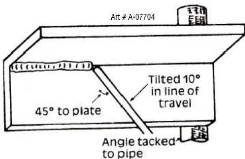
Figure 6-19: Overhead fillet weld
6.17 Distortion
Distortion in some degree is present in all forms of welding. In many cases it is so small that it is barely perceptible, but in other cases allowance has to be made before welding commences for the distortion that will subsequently occur. The study of distortion is so complex that only a brief outline can be attempted hear.
6.18 The Cause of Distortion
Distortion is cause by:
A. Contraction of Weld Metal:
Molten steel shrinks approximately 11 per cent in volume on cooling to room temperature. This means that a cube of molten metal would contract approximately 2.2 per cent in each of its three dimensions. In a welded joint, the metal becomes attached to the side of the joint and cannot contract freely. Therefore, cooling causes the weld metal to flow plastically, that is, the weld itself has to stretch if it is to overcome the effect of shrinking volume and still be attached to the edge of the joint. If the restraint is very great, as, for example, in a heavy section of plate, the weld metal may crack. Even in cases where the weld metal does not crack, there will still remain stresses “locked-up” in the structure. If the joint material is relatively weak, for example, a butt joint in 2.0mm sheet, the contracting weld metal may cause the sheet to become distorted.
B. Expansion and Contraction of Parent Metal in the Fusion Zone:
While welding is proceeding, a relatively small volume of the adjacent plate material is heated to a very high temperature and attempts to expand in all directions. It is able to do this freely at right angles to the surface of the plate (i.e., “through the weld”), but when it attempts to expand “across the weld” or “along the weld”, it meets considerable resistance, and to fulfil the desire for continued expansion, it has to deform plastically, that is, the metal adjacent to the weld is at a high temperature and hence rather soft, and, by expanding, pushes against the cooler, harder metal further away, and tends to bulge (or is “upset”). When the weld area begins to cool, the “upset” metal attempts to contract as much as it expanded, but, because it has been “upset”, it does not resume its former shape, and the contraction of the new shape exerts a strong pull on adjacent metal. Several things can then happen.
The metal in the weld area is stretched (plastic deformation), the job may be pulled out of shape by the powerful contraction stresses (distortion), or the weld may crack, in any case, there will remain “locked-up” stresses in the job. Figures 6-20 and 6-21 illustrate how distortion is created.
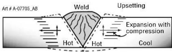
Figure 6-20: Parent metal expansion
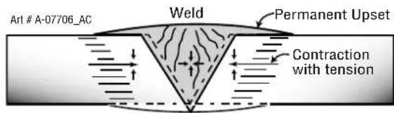
Figure 6-21: Parent metal contraction
6.19 Overcoming Distortion Effects
There are several methods of minimising distortion effects.
A. Peening
This is done by hammering the weld while it is still hot. The weld metal is flattened slightly and because of this the tensile stresses are reduced a little. The effect of peening is relatively shallow, and is not advisable on the last layer.
B. Distribution of Stresses
Distortion may be reduced by selecting a welding sequence which will distribute the stresses suitably so that they tend to cancel each other out. See Figures 6-25 through 6-28 for various weld sequences. Choice of a suitable weld sequence is probably the most effective method of overcoming distortion, although an unsuitable sequence may exaggerate it. Simultaneous welding of both sides of a joint by two welders is often successful in eliminating distortion.
C. Restraint of Parts
Forcible restraint of the components being welded is often used to prevent distortion. Jigs, positions, and tack welds are methods employed with this in view.
D. Presetting
It is possible in some cases to tell from past experience or to find by trial and error (or less frequently, to calculate) how much distortion will take place in a given welded structure. By correct pre-setting of the components to be welded, constructional stresses can be made to pull the parts into correct alignment. A simple example is shown in Figure 6-22.
E. Preheating
Suitable preheating of parts of the structure other than the area to be welded can be sometimes used to reduce distortion. Figure 6-23 shows a simple application. By removing the heating source from b and c as soon as welding is completed, the sections b and c will contract at a similar rate, thus reducing distortion.
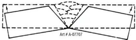
Figure 6-22: Principle of presetting
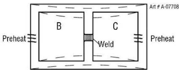
Dotted lines show effect if no preheat is used
Figure 6-23: Reduction of distortion by preheating
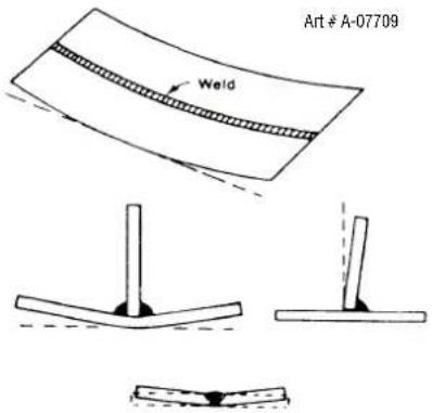
Figure 6-24: Examples of distortion
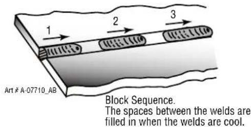
Figure 6-25: Welding sequence
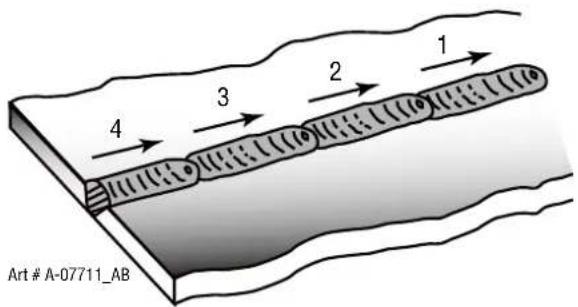
Figure 6-26: Step back sequence
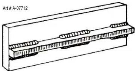
natural_image
Technical line drawing of a mechanical component with threaded fasteners (no text or symbols)Figure 6-27: Chain intermittent welding
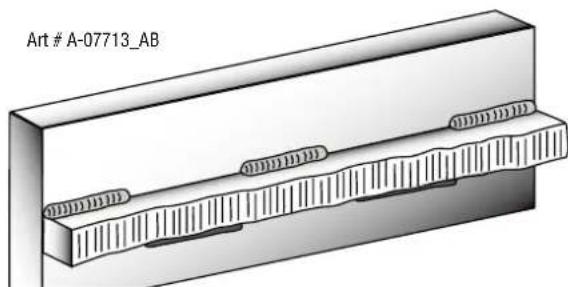
natural_image
Technical illustration of a mechanical component with threaded fasteners and a labeled section (Art # A-07713_AB), no readable text or symbols beyond the label.Figure 6-28: Staggered intermittent welding
6.20 Welding Problems
| Description Possible Cause | Remedy | |
| 1 Gas pockets or voids in weld metal (Porosity) | A Electrodes are damp A Dry electrodes before useB Welding current is too high B Reduce welding currentC Surface impurities such as oil, grease, paint, etc | |
| 2 Crack occurring in weld metal soon after solidification commences | A Rigidity of joint A Redesign to relieve weldjoint of severe stresses or use crack resistance electrodesB Insufficient throat thickness BTravel slightly slower to alloy greater build-up in throatC Cooling rate is too high C Preheat plate and cool slowly | |
| 3 A gap is left by failure of the weld metal to fill the root of the weld | A Welding current is too low A Increase welding currentB Electrode too large for joint B Use smaller diameter electrodeC Insufficient gap C Allow wider gapD Incorrect sequenceD Use correct build-up sequence | |
Art # A-05866_AC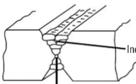 correct SequenceInsufficient GapFigure 6-29: Example of Insufficient Gap or Incorrect Sequence correct SequenceInsufficient GapFigure 6-29: Example of Insufficient Gap or Incorrect Sequence | ||
| 4 Portions of the weld run do not fuse to the surface of the metal or edge of the joint | A Small electrodes used on heavy cold plate | A Use larger electrodes and preheat the plate |
| B Welding current is too low B Increase welding current | ||
| C Wrong electrode angle | C Adjust angle so the welding arc is directed more into the base metal | |
| D Travel speed of electrode is too high | D Reduce travel speed of electrode | |
| E Scale or dirt on joint surface | E Clean surface before welding | |
Lack of fusion caused by dirt, electrode angle incorrect, rate of travel too high
Art # A-05867_AC
Lack of side fusion, scale dirt, small electrode, amperage too low
Lack of inter-run fusion
Lack of root fusion
Figure 6-30: Example of Lack of Fusion
| Description Possible Cause | Remedy | |
| 5 A groove has been formed in the base metal adjacent to the toe of a weld and has not been filled by the weld metal (undercut). | A Welding current is too high. A Reduce welding currentB Welding arc is too long. B Reduce the length of the welding arcC Angle of the electrode is incorrect.D Joint preparation does not allow correct electrode angle.E Electrode too large for joint. E Use smaller gauge electrode.F Insufficient deposit time at edge of weave. | F Pause for a moment at edge of weave to allow weld metal build-up. |
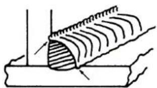
natural_image
Diagram of a mechanical joint or pipe section with hatched shading, no text or symbols presentArt # A-07714
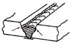
natural_image
Technical line drawing of a mechanical joint or seal assembly (no text or symbols)Figure 6-31: Examples of undercut
| Description Possible Cause Remedy | ||
| 6 Non-metallic particles are trapped in the weld metal (slag inclusion) | A Non-metallic particles may be trapped in undercut from previous runB Joint preparation too restrictedC Irregular deposits allow slag to be trappedD Lack of penetration with slag trapped beneath weld beadE Rust or mill scale is preventing full fusionF Wrong electrode for position in which welding is done | A If bad undercut is present, clean slag out and cover with a run from a smaller diameter electrodeB Allow for adequate penetration and room for cleaning out the slagC If very bad, chip or grind out irregularitiesD Use smaller electrode with sufficient current to give adequate penetration. Use suitable tools to remove all slag from cornersE Clean joint before weldingF Use electrodes designed for position in which welding is done, otherwise proper control of slag is difficult |
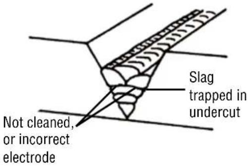 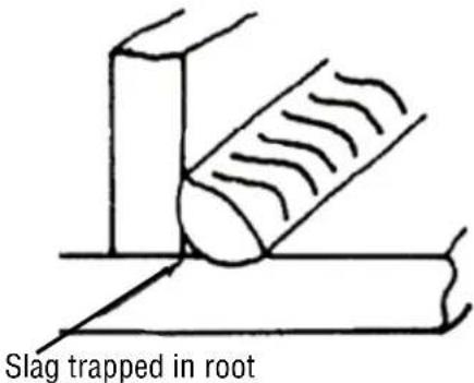 Art # A-05868_ACFigure 6-32: Examples of Slag Inclusion Art # A-05868_ACFigure 6-32: Examples of Slag Inclusion | ||
Table 6-2: Welding Problems
This Page Intentionally Blank
SECTION 7:
TIG (GTAW) WELDING
7.01 Shielding Gas Regulator/Flowmeter Operating Instructions
WARNING
This equipment is designed for use with welding grade (Inert) shielding gases only.
Shielding Gas Regulator/Flowmeter Safety
This regulator/flowmeter is designed to reduce and control high pressure gas from a cylinder or pipeline to the working pressure required for the equipment using it.
If the equipment is improperly used, hazardous conditions are created that may cause accidents. It is the users responsibility to prevent such conditions. Before handing or using the equipment, understand and comply at all times with the safe practices prescribed in this instruction.
SPECIFIC PROCEDURES for the use of regulators/flowmeters are listed below.
- NEVER subject the regulator/flowmeter to inlet pressure greater than its rated inlet pressure.
- NEVER pressurize a regulator/flowmeter that has loose or damaged parts or is in a questionable condition. NEVER loosen a connection or attempt to remove any part of a regulator/flowmeter until the gas pressure has been relieved. Under pressure, gas can dangerously propel a loose part.
- DO NOT remove the regulator/flowmeter from a cylinder without first closing the cylinder valve and releasing gas in the regulator/flowmeter high and low pressure chambers.
- DO NOT use the regulator/flowmeter as a control valve. When downstream equipment is not in use for extended periods of time, shut off the gas at the cylinder valve and release the gas from the equipment.
- OPEN the cylinder valve SLOWLY. Close after use.
User Responsibilities
This equipment will perform safely and reliable only when installed, operated and maintained, and repaired in accordance with the instructions provided. Equipment must be checked periodically and repaired, replaced, or reset as necessary for continued safe and reliable performance. Defective equipment should not be used. Parts that are broken, missing, obviously worn, distorted, or contaminated should be replaced immediately.
The user of this equipment will generally have the sole responsibility for any malfunction, which results from improper use, faulty maintenance, or by repair by anyone other than an accredited repairer.
CAUTION
Match regulator/flowmeter to cylinder. NEVER CONNECT a regulator/flowmeter designed for a particular gas or gases to a cylinder containing any other gas.
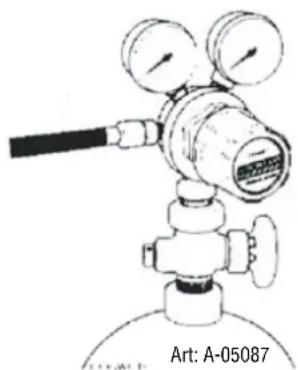
natural_image
Line drawing of a gas regulator with two gauges and a valve, labeled Art: A-05087 (no text or symbols on the diagram itself)Figure 7-1: Fit Regulator/flowmeter to Cylinder
Installation
- Remove cylinder valve plastic dust seal. Clean the cylinder valve outlet of impurities that may clog orifices and damage seats before connecting the regulator/flowmeter.
Crack the valve (open then close) momentarily, pointing the outlet away from people and sources of ignition. Wipe with a clean lint free cloth. - Match regulator/flowmeter to cylinder. Before connecting, check that the regulator/flowmeter label and cylinder marking agree and that the regulator/flowmeter inlet and cylinder outlet match. NEVER CONNECT a regulator/flowmeter designed for a particular gas or gases to a cylinder containing any other gas.
- Connect the regulator/flowmeter inlet connection to cylinder or pipeline and tighten it firmly but not excessively, with a suitable spanner.
- Connect and tighten the outlet hose firmly and attach down-stream equipment.
- To protect sensitive down-stream equipment a separate safety device may be necessary if the regulator/flowmeter is not fitted with a pressure relief device.
Operation
With the regulator/flowmeter connected to cylinder or pipeline, and the adjustment screw/knob fully disengaged, pressurize as follows:
- Stand to one side of regulator/flowmeter and slowly open the cylinder valve. If opened quickly, a sudden pressure surge may damage internal regulator/flowmeter parts.
- With valves on downstream equipment closed, adjust regulator/flowmeter to approximate working pressure. It is recommended that testing for leaks at the regulator/flowmeter connection points be carried out using a suitable leak detection solution or soapy water.
- Purge air or other unwanted welding grade shielding gas from equipment connected to the regulator/flowmeter by individually opening then closing the equipment control valves. Complete purging may take up to ten seconds or more, depending upon the length and size of the hose being purged.
Adjusting Flow Rate
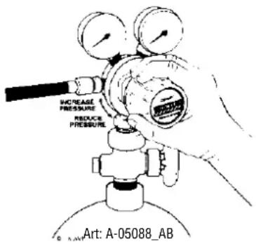
Figure 7-2: Adjust Flow Rate
With the regulator/flowmeter ready for operation, adjust working flow rate as follows:
- Slowly turn adjusting screw/knob in (clockwise) direction until the outlet gauge indicates the required flow rate.

NOTE!
It may be necessary to re-check the shielding gas regulator/flowmeter flow rate following the first weld sequence due to back pressure present within shielding gas hose assembly.
- To reduce flow rate, allow the welding grade shielding gas to discharge from regulator/flowmeter by opening the downstream valve. Bleed welding grade shielding gas into a well ventilated area and away
from any ignition source. Turn adjusting screw counterclockwise, until the required flow rate is indicated on the gauge. Close downstream valve.
Shutdown
Close cylinder valve whenever the regulator/flowmeter is not in use. To shut down for extended periods (more than 30 minutes).
- Close cylinder or upstream valve tightly.
- Open downstream equipment valves to drain the lines. Bleed gas into a well ventilated area and away from any ignition source.
- After gas is drained completely, disengage adjusting screw and close downstream equipment valves.
- Before transporting cylinders that are not secured on a cart designed for such purposes, remove regulators/flowmeters.
7.02 Setup For Lift TIG (GTAW) Welding
A. Select Lift TIG mode with the process selection control (refer to Section 4.02.1 for further information).
B. Connect the TIG Torch to the negative welding terminal (-). Refer to Note below for Optional TIG Torch information. Welding current flows from the power source via Dinse type terminals. It is essential, however, that the male plug is inserted and turned securely to achieve a sound electrical connection.
C. For WeldSkill 155 use Tig Torch W7003021. Refer to Table 2-2 on Page 2-6 for Options and accessories.
There are two TIG Torch options for WeldSkill 185. Refer to Table 2-2 on Page 2-6 for Options and accessories.
For WeldSkill 185, connect the TIG torch trigger switch and remote current control if applicable via the 8 pin socket located on the front of the Power Source. The TIG torch will require a trigger switch to weld in LIFT TIG Mode.
D. Connect the work lead to the positive welding terminal (+). Welding current flows from the Power Source via Dinse type terminals. It is essential, however, that the male plug is inserted and turned securely to achieve a sound electrical connection.
E. Connect the Argon Regulator/Flowmeter to the Welding Grade Argon Shielding Gas Cylinder then connect the TIG Torch gas hose to regulator. Before turning on shielding gas check that all fittings are tight and the gas valve on the TIG torch is turned off. Before commencing to TIG weld open TIG torch gas valve to allow sufficient shielding gas flow when welding. Refer to Section 7.03 for recommended Shielding Gas flow rates and other TIG Welding information.
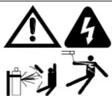
WARNING
Secure the welding grade shielding gas cylinder in an upright position by chaining it to a suitable stationary support to prevent falling or tipping.
Open Gas Cylinder Valve carefully.
WARNING
Before connecting the work clamp to the work piece and inserting the electrode in the TIG torch make sure the Mains power supply is switched off.
CAUTION
Remove any packaging material prior to use. Do not block the air vents at the front or rear of the Welding Power Source.

NOTE!
The TIG Torch is NOT supplied. It is an optional accessory. Refer to Table 2-2 on Page 2-6 for optional accessory information.
Refer over page to Lift TIG Welding Setup diagrams.

NOTE!
If the TIG torch has a trigger switch or a remote TIG torch current control fitted then it will require to be connected to the 8 pin socket. (Refer to section 4.02.12 Remote Control Socket for further information)..
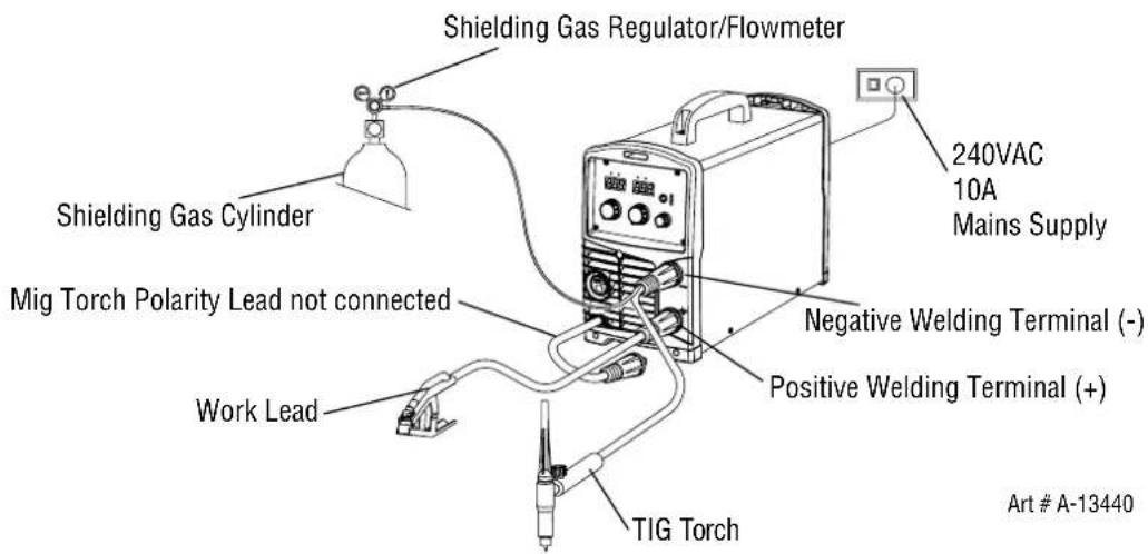
Figure 7-3: Setup For Lift TIG (GTAW) Welding for WeldSkill 155
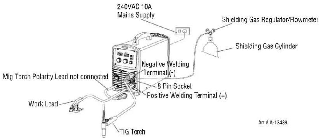
Figure 7-4: Setup For Lift TIG (GTAW) Welding for WeldSkill 185
7.03 TIG (GTAW) Basic Welding Technique
Gas Tungsten Arc Welding (GTAW) or TIG (Tungsten Inert Gas) as it is commonly referred to, is a welding process in which fusion is produced by an electric arc that is established between a single tungsten (non-consumable) electrode and the work piece. Shielding is obtained from a welding grade shielding gas or welding grade shielding gas mixture which is generally Argon based. A filler metal may also be added manually in some circumstances depending on the welding application.
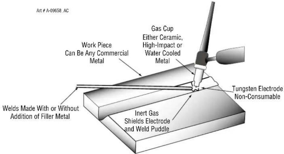
Figure 7-5: TIG Welding Application Shot
Tungsten Electrode Current Ranges
| Electrode Diameter DC Current (Amps) |
| 0.040” (1.0mm) 30-60 |
| 1/16” (1.6mm) 60-115 |
| 3/32” (2.4mm) 100-165 |
| 1/8” (3.2mm) 135-200 |
| 5/32” (4.0mm) 190-280 |
| 3/16” (4.8mm) 250-340 |
Table 7-1: Current Ranges for Various Tungsten Electrode Sizes
Guide for Selecting Filler Wire Diameter
| Filler Wire Diameter DC Current Range (Amps) |
| 1/16” (1.6mm) 20-90 |
| 3/32” (2.4mm) 65-115 |
| 1/8” (3.2mm) 100-165 |
| 3/16” (4.8mm) 200-350 |
Table 7-2: Filler Wire Selection Guide

NOTE!
The operator should use the welding current range values as a guide only, then finally adjust the current setting to suit the application.
Tungsten Electrode Types
| Electrode Type (Ground Finish) | Welding Application Features | Colour Code | |
| Ceriated 2% | AC & DC welding of mild steel, stainless steel, copper, aluminium, magnesium and their alloys | Longer life, More stable arc, Easier starting, Wider current range, Narrower more concentrated arc. | Grey |
Table 7-3
TIG Welding Filler Rods
| Comweld Rod | Aust Std | AWS Std Part | No. 1.6mm | Part No. 2.4mm | Part No. 3.2mm | Type/Application |
| LW1 | R4 | ER70S-4 | 321411 | — | — | For mild-medium strength steels. |
| LW1-6 | R6 | ER70S-6 | 321417 | — | — | Pipes, tubing, roll cages, etc. |
| Supersteel | R2 | ER70S-2 | 321370 | — | — | |
| CrMo1 | RB2 | ER80S-B2 | — | 321379 | — | For welding of high strength |
| CrMo2 | RB3 | ER90S-B3 | — | 321383 | — | Cr-Mo steels used at elevated temperatures. |
| 308L | R308L | ER308L | 321406 | 321407 | — | For stainless steels. Stainless pipes, tubing, architectural uses, etc. |
| 309L | R309L | ER309L | 321403 | 321404 | — | |
| 316L | R316L | ER316L | 321400 | 321401 | — |
Table 7-4
| Base Metal Thickness | DC Current for Mild Steel | DC Current for Stainless Steel | Tungsten Electrode Diameter | Filler Rod Diameter (if required) | Argon Gas Flow Rate Litres/min | Joint Type |
| 0.040”1.0mm | 35-4540-50 | 20-3025-35 | 0.040”1.0mm | 1/16”1.6mm | 5-7 Butt/CornerLap/Fillet | |
| 0.045”1.2mm | 45-5550-60 | 30-4535-50 | 0.040”1.0mm | 1/16”1.6mm | 5-7 Butt/CornerLap/Fillet | |
| 1/16”1.6mm | 60-7070-90 | 40-6050-70 | 1/16”1.6mm | 1/16”1.6mm | 7 Butt/CornerLap/Fillet | |
| 1/8”3.2mm | 80-10090-115 | 65-8590-110 | 1/16”1.6mm | 3/32”2.4mm | 7 Butt/CornerLap/Fillet | |
| 3/16”4.8mm | 115-135140-165 | 100-125125-150 | 3/32”2.4mm | 1/8”3.2mm | 10 Butt/CornerLap/Fillet | |
| 1/4”6.4mm | 160-175170-200 | 135-160160-180 | 1/8”3.2mm | 5/32”4.0mm | 10 Butt/CornerLap/Fillet |
Table 7-5
TIG Welding is generally regarded as a specialised process that requires operator competency. While many of the principles outlined in the previous Arc Welding section are applicable a comprehensive outline of the TIG Welding process is outside the scope of this Operating Manual. For further information please refer to www.cigweld.com.au or contact Cigweld.
7.04 TIG (GTAW) Welding Problems
| FAULT CAUSE REMEDY | ||
| 1 Excessive bead build up or poor penetration or poor fusion at edges of weld. | Welding current is too low | Increase weld current and/or faulty joint preparation. |
| 2 Weld bead too wide and flat or undercut at edges of weld or excessive burn through. | Welding current is too high | Decrease weld current. |
| 3 Weld bead too small or insufficient penetration or ripples in bead are widely spaced apart. | Travel speed too fast Reduce travel speed. | |
| 4 Weld bead too wide or excessive bead build up or excessive penetration in butt joint. | Travel speed too slow Increase travel speed. | |
| 5 Uneven leg length in fillet joint | Wrong placement of filler rod | Re-position filler rod. |
| 6 Electrode melts or oxidises when an arc is struck. | A Torch lead connected to positive welding terminal.B No shielding gas flowing to welding region.C Torch is clogged with dust or dirt.D Shielding gas hose is damaged.E Shielding gas regulator turned off.F The electrode is too small for the welding current. | A Connect torch lead to negative welding terminal.B Check the shielding gas lines for kinks or breaks and shielding gas cylinder contents.C Clean torch.D Replace shielding gas hose.E Turn On Shielding Gas and adjust Shielding Gas flow rate for the welding job. Refer to Table 7-5 on Page 7-7.F Increase electrode diameter or reduce the welding current. |
| 7 Dirty weld pool A Electrode contaminated by contact with work piece or filler rod material.B Work piece surface has foreign material on it.C Shielding gas contaminated with air. | A Clean the electrode by grinding off the contaminates.B Clean surface.C Check shielding gas lines for cuts and loose fitting or change shielding gas cylinder. | |
| 8 Poor weld finish Inadequate shielding gas. | Increase shielding gas flow or check shielding gas line for shielding gas flow problems. | |
| 9 Arc start is not smooth. A Tungsten electrode is too large for the welding current.B The wrong electrode is being used for the welding job.C Shielding gas flow rate is too high.D Incorrect shielding gas is being used.E Poor work clamp connection to work piece. | A Select the right size tungsten electrode.Refer to Table 7-1 Cigweld Tungsten Electrode Selection Chart.B Select the right size tungsten electrode type. Refer to Table 7-1 Cigweld Tungsten Electrode Selection Chart.C Select the right shielding gas flow rate for the welding job. Refer to Table 7-5 on page 7-7D Select the correct shielding gas.E Improve connection to work piece. | |
| 10 Arc flutters during TIG welding. | Tungsten electrode is too large for the welding current. | Select the right size tungsten electrode.Refer to Table 7-1 Cigweld Tungsten Electrode Selection Chart. |
Table 7-6: TIG (GTAW) Welding Problems
SECTION 8:
ROUTINE SERVICE REQUIREMENTS AND POWER SOURCE PROBLEMS
8.01 Routine Maintenance & Inspection
WARNING
There are extremely dangerous voltage and power levels present inside this product. Do not attempt to open or repair unless you are a qualified electrical tradesperson. Disconnect the Welding Power Source from the Mains Supply Voltage before disassembling.
Welding equipment should be regularly checked by a qualified electrical tradesperson to ensure that:
- The main earth wire of the electrical installation is intact.
- Power point for the Welding Power Source is effectively earthed and of adequate current rating.
- Plugs and cord extension sockets are correctly wired.
- Flexible cord is of the 3-core tough rubber or plastic sheathed type of adequate rating, correctly connected and in good condition.
- Welding terminals are shrouded to prevent inadvertent contact or short circuit.
- The frame of the Welding Power Source is effectively earthed.
- Welding leads and electrode holder are in good condition.
- The Welding Power Source is clean internally, especially from metal filing, slag, and loose material. If any parts are damaged for any reason, replacement is recommended.
8.02 Cleaning the Welding Power Source
WARNING
There are extremely dangerous voltage and power levels present inside this product. Do not attempt to open or repair unless you are a qualified electrical tradesperson. Disconnect the Welding Power Source from the Mains Supply Voltage before disassembling.
To clean the Welding Power Source, open the enclosure and use a vacuum cleaner to remove any accumulated dirt, metal filings, slag and loose material. Keep the shunt and lead screw surfaces clean as accumulated foreign material may reduce the welders output welding current.
CAUTION
Do not use compressed air to clean the Welding Power Source. Compressed air can force metal particles to lodge between live electrical parts and earthed metal parts within the Welding Power Source. This may result in arcing between this parts and their eventual failure.
8.03 Cleaning the Feed Rolls
Clean the grooves in the drive rolls frequently. This can be done by using a small wire brush. Also wipe off or clean the grooves on the upper feed roll. After cleaning, tighten the feed roll retaining knobs.
8.04 Basic Troubleshooting
WARNING
There are extremely dangerous voltage and power levels present inside this product. Do not attempt to open or repair unless you are a qualified electrical tradesperson and you have had training in power measurements and troubleshooting techniques.
If major complex subassemblies are faulty, then the Welding Power Source must be returned to an Accredited CIGWELD Service Agent for repair.
The basic level of troubleshooting is that which can be performed without special equipment or knowledge.
8.05 Welding Power Source Problems
| PROBLEM CAUSE REMEDY | ||
| 1 Mains Supply Voltage is On, the On/Off switch on the rear panel is in the On position and the Power indicator on the front panel is illuminated however the power source will not MIG weld. | A Power source is not in the correct mode of operation. | A Set the power source to MIG mode. Refer to Section 4.02.1. |
| B MIG Torch Polarity Lead is not connected. | B Connect the MIG Torch Polarity Lead to the positive or negative output terminal. Refer to Section 4.02.11. | |
| C Work Lead is not connected to the work piece. | C Ensure that the Work Lead is connected to the work piece and has a good connection to the work piece. Refer to Set Up for MIG Section 5.09 or 5.10. | |
| D MIG torch is not correctly connected to the Euro Style MIG Torch Adaptor. | D Ensure that the MIG torch is correctly connected to the Euro Style MIG Torch Adaptor. Refer to Section 4.02.5 & 5.02. | |
| 2 Mains Supply Voltage is On, the On/Off switch on the rear panel is in the On position and the Power indicator on the front panel is illuminated however the power source will not STICK weld. | A Power source is not in the correct mode of operation. | A Set the power source to STICK mode. Refer to Section 4.02.1. |
| B Work Lead is not connected to the work piece. | B Ensure that the Work Lead is connected to the work piece and has a good connection to the work piece. | |
| 3 Mains Supply Voltage is On, the On/Off switch on the rear panel is in the On position and the Power indicator on the front panel is illuminated however the power source will not TIG weld. | A Power source is not in the correct mode of operation. | A Set the power source to LIFT TIG mode. Refer to Section 4.02.1. |
| B Work Lead is not connected to the work piece. | B Ensure that the Work Lead is connected to the work piece and has a good connection to the work piece. | |
| C TIG Torch 8 Pin Control Plug not connected correctly or loose/faulty connection in plug. (WeldSkill 185 only) | C Connect 8 Pin TIG Torch control plug securely and correctly to the 8 Pin control socket of the front of the Transmig 175i+ Power Source. (WeldSkill 185 only)Repair or replace if faulty. (WeldSkill 185 only) | |
| D Faulty TIG Torch Trigger. (WeldSkill 185 only) | D Repair or replace TIG Torch Trigger switch/lead. | |
| 4 Mains Supply Voltage is On, the On/Off switch in the rear panel is in the On position but the Power On indicator on the front panel is Not illuminated and the digital displays on the front panel are also not illuminated and the power source will not weld. | This may occur due to the activation of an in-built protective device if the Power Source is repeatedly switched On then Off rapidly or the supply to the Power Source is switched On then Off rapidly. | If this occurs leave the Power Source On/Off switch in the Off position for several minutes to allow the protective device to reset. |
| 5 Over Temp Indicator is illuminated and unit will not commence welding when the torch trigger switch is depressed. | Duty cycle of power source has been exceeded. | Leave the power source switched ON and allow it to cool. Note that Over Temp indicator must be extinguished prior to commencement of welding. |
| 6 Unit will not feed wire in MIG mode. | A Incorrect Feed Roll fitted for wire type being used. (WeldSkill 185 only) | A Fit the correct feed roll for MIG wire type being used. Refer to section 2.11 for optional feed rolls available and Section 5.07 for feed roll fitting details. (WeldSkill 185 only) |
| B Pressure Roller Arm is not secured in the down position or not correctly adjusted. | B Secure Pressure Roller in the down position and ensure that it is correctly adjusted. Refer to Section 5.05 and 5.06. | |
| C Electrode wire stuck in conduit liner or contact tip (burn-back jam). | C Check for clogged / kinked MIG torch conduit liner or worn contact tip. Replace faulty components. | |
| D Internal fault in power source | D Have an Accredited CIGWELD Service Provider investigate the fault. | |
| 7 Welding wire continues to feed when torch trigger is released. | A Trigger mode selection switch is in 4T latch mode. | A Change the trigger mode selection switch from 4T latch mode to 2T normal mode. |
| B Torch trigger leads shorted. | B Repair or replace torch trigger switch/lead. | |
| 8 Welding arc cannot be established in MIG mode. | A MIG torch polarity lead is not connected into a welding output terminal. | A Connect the MIG torch polarity lead to either the positive welding output terminal or the negative welding output terminal as required. |
| B Poor or no work lead contact. | B Clean work clamp area and ensure good electrical contact. | |
| 9 Inconsistent wire feed. A Worn | or dirty contact tip. A Replace if necessary. | |
| B Worn feed roll. B Replace. | ||
| C Excessive brake tension on wire reel hub. | C Reduce brake tension on spool hub | |
| D Worn, kinked or dirty conduit liner | D Clean or replace conduit liner | |
| 10 No gas flow in MIG mode. A Gas | gas hose is damaged. A Replace or repair. | |
| B Gas passage contains impurities. | B Disconnect gas hose from the rear of power source or wirefeeder and blow out impurities. | |
| C Gas regulator turned off. C Turn on regulator. | ||
| D Empty gas cylinder. D Replace gas cylinder. | ||
| 11 Gas flow continues after the torch trigger switch has been released (MIG mode). | Gas valve has jammed open due to impurities in the gas or the gas line. | Have an accredited CIGWELD service provider repair or replace gas valve. |
| 12 Power indicator will not illuminate and welding arc cannot be established. | The mains supply voltage has exceeded voltage limits of the power source. | Ensure that the mains supply voltage is within 240VAC ± 15%. |
| 13 TIG electrode melts when arc is struck. | TIG torch is connected to the (+) VE terminal. | Connect the TIG torch to the (-) VE terminal. |
| 14 Arc flutters during TIG welding. | Tungsten electrode is too large for the welding current. | Select the correct size of tungsten electrode. Refer to Table 6-1. |
Table 8-1
SECTION 9: KEY SPARE PARTS
9.01 WeldSkill 155 Key Spare Parts
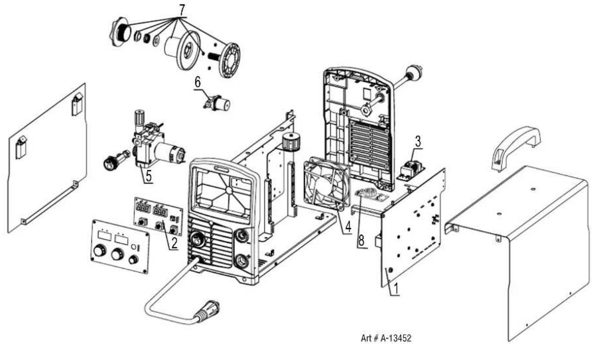
Figure 9-1
| WELDSKILL 155 POWER SOURCE KEY SPARE PARTS | ||
| ITEM PART NUMBER DESCRIPTION | ||
| 1 W7006865 PCBA Power Inverter | ||
| 2 W7006866 PCBA Front Panel | ||
| 3 W7006806 PCBA EMC Filter | ||
| 4 W7006867 Fan Assembly | ||
| 5 W7006868 Wire Drive Assembly | ||
| 6 W7006869 Gas Solenoid Valve 24VDC | ||
| 7 W7006870 Spool Hub Assembly | ||
| 8 W7006884 PCBA Wire Feed Filter | ||
Table 9-1
9.02 WeldSkill 185 Key Spare Parts
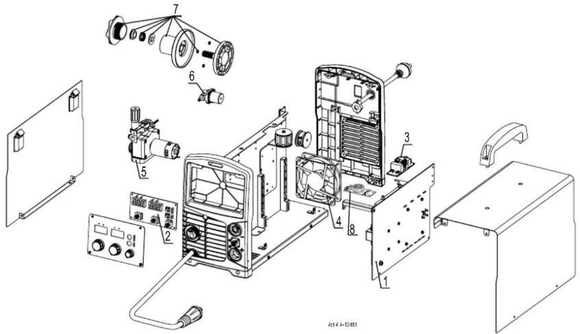
Figure 9-2
| WELDSKILL 185 POWER SOURCE KEY SPARE PARTS | ||
| ITEM PART NUMBER DESCRIPTION | ||
| 1 W7006830 PCBA Power Inverter | ||
| 2 W7006831 PCBA Front Panel | ||
| 3 W7006806 PCBA EMC Filter | ||
| 4 W7006867 Fan Assembly | ||
| 5 W7006868 Wire Drive Assembly | ||
| 6 W7006869 Gas Solenoid Valve 24VDC | ||
| 7 W7006870 Spool Hub Assembly | ||
| 8 W7006834 PCBA Wire Feed Filter | ||
Table 9-2
9.03 E-180 MIG Torch 3m (P/N W4018800) Key Spare Parts
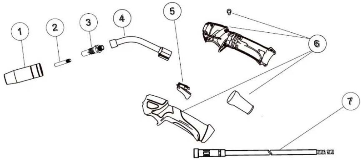
Figure 9-3
| MIG TORCH KEY SPARE PARTS | ||
| ITEM PART NUMBER DESCRIPTION | ||
| 1 W6000600 Nozzle | ||
| 2 | OTW11/23/R Contact Tip 0.6mm | |
| OTW11/30/R Contact Tip 0.8mm | ||
| OTW11/35/R Contact Tip 0.9mm | ||
| OTW11/40/R Contact Tip 1.0mm | ||
| OTW11/45/R Contact Tip 1.2mm | ||
| 3 W6000606 Diffuser | ||
| 4 W6000607 Conductor Tube | ||
| 5 W6000608 Trigger Assembly | ||
| 6 W6000609 Handle Mouldings (includes handle mouldings, screws, cable support) | ||
| 7 | WS1240015/R Conduit Liner Steel 5m, 0.6-1.0mm Blue (hard wires) | |
| WS1240031/R Conduit Liner Steel 4m, 1.0-1.2mm Red (hard wires) | ||
| WS1260026/R Conduit Liner Teflon 4m, 0.8-1.2mm Red (soft wires) | ||
| WS0010304/R Jump Liner 1.0-1.2mm | ||
Table 9-3
This page is intentionally blank.
APPENDIX 1: WELDSKILL 155 CIRCUIT DIAGRAM
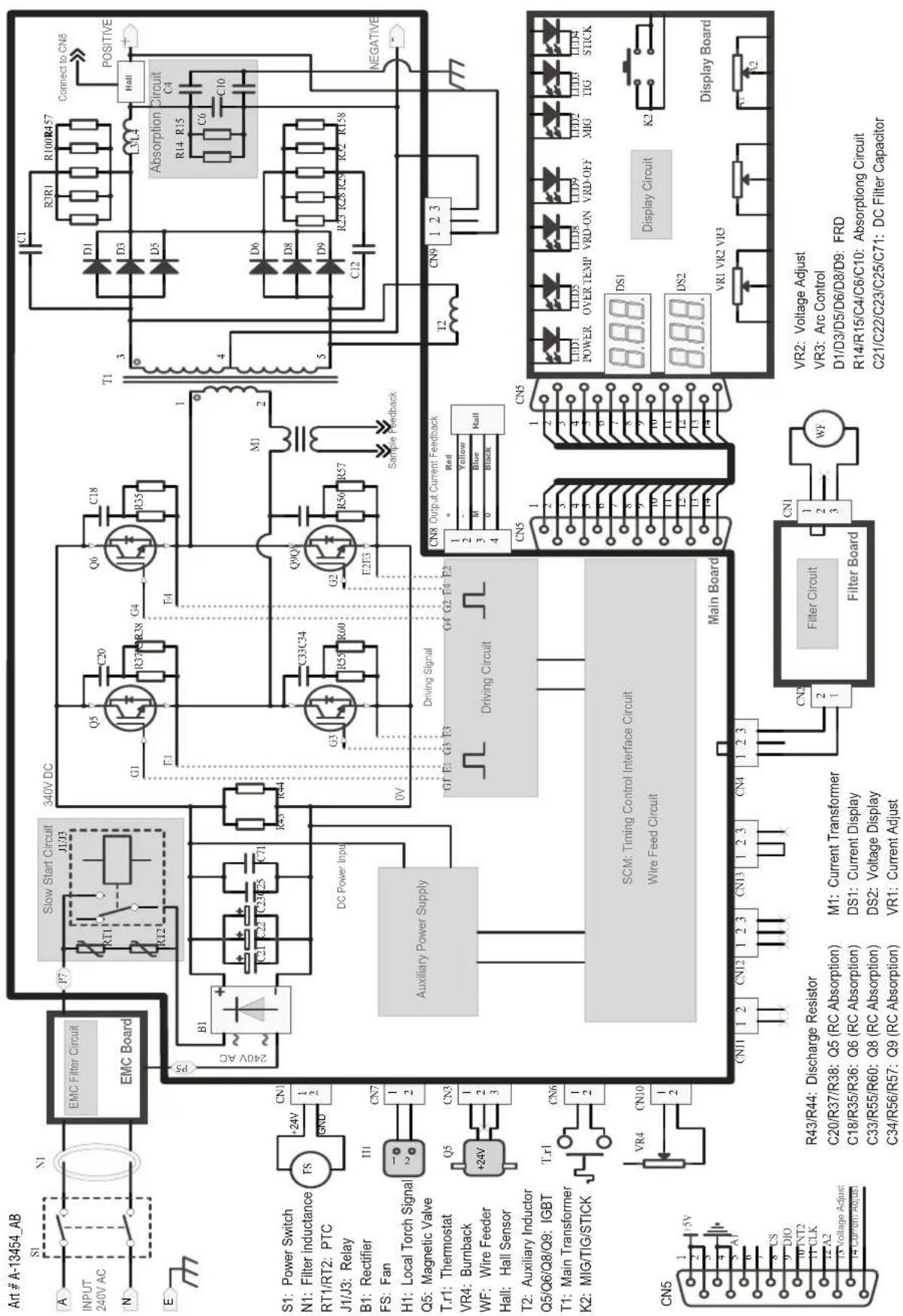
APPENDIX 2: WELDSKILL 185 CIRCUIT DIAGRAM
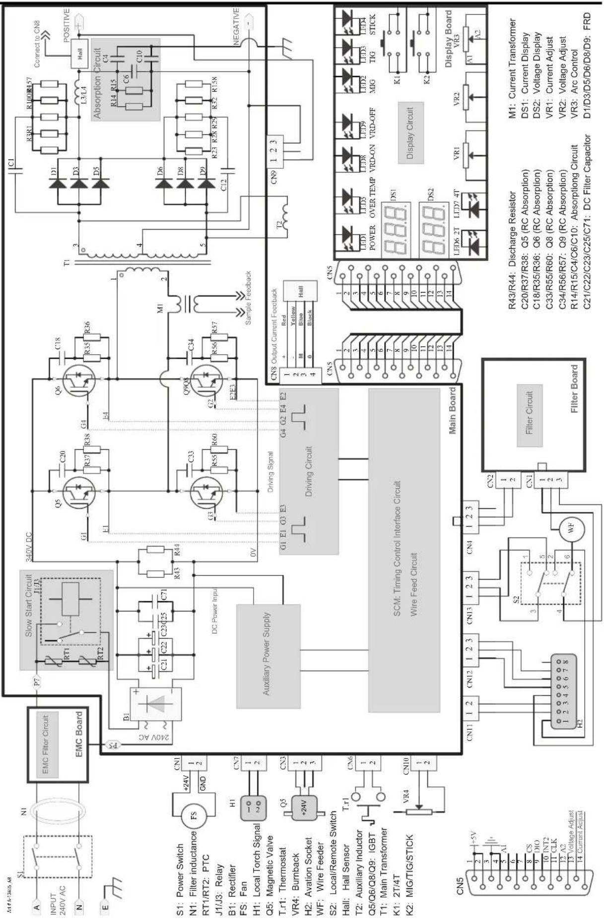
CIGWELD - LIMITED WARRANTY TERMS
LIMITED WARRANTY: CIGWELD Pty Ltd, An ESAB Brand, hereafter, "CIGWELD" warrants to customers of its authorized distributors hereafter "Purchaser" that its products will be free of defects in workmanship or material. Should any failure to conform to this warranty appear within the time period applicable to the CIGWELD products as stated below, CIGWELD shall, upon notification thereof and substantiation that the product has been stored, installed, operated, and maintained in accordance with CIGWELD's specifications, instructions, recommendations and recognized standard industry practice, and not subject to misuse, repair, neglect, alteration, or accident, correct such defects by suitable repair or replacement, at CIGWELD's sole option, of any components or parts of the product determined by CIGWELD to be defective.
CIGWELD MAKES NO OTHER WARRANTY, EXPRESS OR IMPLIED. THIS WARRANTY IS EXCLUSIVE AND IN LIEU OF ALL OTHERS, INCLUDING, BUT NOT LIMITED TO ANY WARRANTY OF MERCHANTABILITY OR FITNESS FOR ANY PARTICULAR PURPOSE.
LIMITATION OF LIABILITY: CIGWELD SHALL NOT UNDER ANY CIRCUMSTANCES BE LIABLE FOR SPECIAL, INDIRECT OR CONSEQUENTIAL DAMAGES, SUCH AS, BUT NOT LIMITED TO, LOST PROFITS AND BUSINESS INTERRUPTION. The remedies of the Purchaser set forth herein are exclusive and the liability of CIGWELD with respect to any contract, or anything done in connection therewith such as the performance or breach thereof, or from the manufacture, sale, delivery, resale, or use of any goods covered by or furnished by CIGWELD whether arising out of contract, negligence, strict tort, or under any warranty, or otherwise, shall not, except as expressly provided herein, exceed the price of the goods upon which such liability is based. No employee, agent, or representative of CIGWELD is authorized to change this warranty in any way or grant any other warranty.
PURCHASER'S RIGHTS UNDER THIS WARRANTY ARE VOID IF REPLACEMENT PARTS OR ACCESSORIES ARE USED WHICH IN CIGWELD'S SOLE JUDGEMENT MAY IMPAIR THE SAFETY OR PERFORMANCE OF ANY CIGWELD PRODUCT. PURCHASER'S RIGHTS UNDER THIS WARRANTY ARE VOID IF THE PRODUCT IS SOLD TO PURCHASER BY NON-AUTHORIZED PERSONS.
The warranty is effective for the time stated below beginning on the date that the authorized distributor delivers the products to the Purchaser. Notwithstanding the foregoing, in no event shall the warranty period extend more than the time stated plus one year from the date CIGWELD delivered the product to the authorized distributor.
Any claim under this warranty must be made within the warranty period which commences on the date of purchase of the product. To make a claim under the warranty, take the product (with proof of purchase from a Cigweld Accredited Seller) to the store where you purchased the product or contact Cigweld Customer Care 1300 654 674 for advice on your nearest Service Provider. CIGWELD reserves the right to request documented evidence of date of purchase. CIGWELD or our Accredited Distributor must be notified in writing of its claim within seven (7) days of becoming aware of the basis thereof, and at its own expense returning the goods which are the subject of the claim to CIGWELD or nominated Accredited Distributor/Accredited Service Provider
This warranty is given.
Cigweld Pty Ltd
A.B.N. 56007226815
71 Gower Street, Preston
Victoria, Australia, 3072
Phone: 1300 654 674
Email: enquiries@cigweld.com.au
Website: www.cigweld.com.au
This warranty is provided in addition to other rights and remedies you have under law: Our goods come with guarantees which cannot be excluded under the Australian Consumer Law. You are entitled to replacement or refund for a major failure and to compensation for other reasonably foreseeable loss or damage. You are also entitled to have the goods repaired or replaced if the goods fail to be of acceptable quality and the failure does not amount to a major failure.
Please note that the information detailed in this statement supersedes any prior published data produced by CIGWELD.
WARRANTY SCHEDULE – WELDSKILL 155 & 185 INVERTERS
| WARRANTY WARRANTY PERIOD – (Parts and Labour) | |
| WeldSkill 155 and 185 Inverter Power Source 2 Years | |
| ACCESSORIES WARRANTY PERIOD | |
| MIG torch, electrode holder lead and work lead 3 Months | |
| MIG torch consumable items NIL | |
| Gas regulator/flowmeter (excluding seat assembly, pressure gauges, elastomer seals and "O" rings | 1 Year |
| Regulator seat assemblies and pressure gauges 6 Months | |
| Elastomer seals and "O" rings used in the equipment | 3 Months |
CIGWELD Limited Warranty does not apply to;
- Obsolete goods sold at auction, second-hand goods and prototype goods.
- Consumable Parts for MIG, TIG, Plasma welding, Plasma cutting and Oxy fuel torches, O-rings, fuses, filters or other parts that fail due to normal wear.
Note:
* No employee, agent, or representative of CIGWELD is authorized to change this warranty in any way or grant any other warranty, and CIGWELD shall not be bound by any such attempt. Correction of non-conformities, in the manner and time provided herein, constitutes fulfilment of CIGWELD's obligations to purchaser with respect to the product.
* This warranty is void, and seller bears no liability hereunder, if purchaser used replacement parts or accessories which, in CIGWELD's sole judgment, impaired the safety or performance of any CIGWELD product and if the unit is altered or serviced by an unauthorised CIGWELD Service Provider. Purchaser's rights under this warranty are void if the product is sold to purchaser by unauthorized persons.
This Page Intentionally Blank

CIGWELD Pty Ltd
CIGWELD An ESAB Brand
71 Gower Street, Preston VIC 3072 Australia
Customer Care:
Tel: 1300 654 674 | Fax: 03 9474 7391
Email: enquiries@cigweld.com.au
International Enquiries
Tel: +61 3 9474 7508 | Fax: +61 3 9474 7488
Malaysia -
Lot 151, Jalan Industri 3/5A
Rawang Integrated Industrial Park,
Jln Batu Arang
48000 Rawang Selangor Darul Ehsan
West Malaysia
Tel: 60 3 6092 2988 | Fax: 60 3 6092 1085
Indonesia -
JL Akasia II Blok A-05 No. 10A
Delta Silicon - Lippo Cikarang
Bekasi, 17550
Indonesia
Toll Free: 0 800 1842 867
Tel: +62 21 8990 6095 | Fax: +62 21 8990 6096
- WE APPRECIATE YOUR BUSINESS!
- YOU ARE IN GOOD COMPANY!
- WARNING
- Record the following information for Warranty purposes:
- Be sure this information reaches the operator. You can get extra copies through your supplier.
- CAUTION
- USER RESPONSIBILITY
- DECLARATION OF CONFORMITY
- TABLE OF CONTENTS
- SECTION 1:
- ARC WELDING SAFETY INSTRUCTIONS AND WARNINGS....1-1
- SECTION 2:
- INTRODUCTION 2-1
- SECTION 3:
- INSTALLATION 3-1
- SECTION 4:
- OPERATION 4-1
- SECTION 5:
- MIG (GMAW) WELDING 5-1
- SECTION 6:
- STICK (MMAW) WELDING 6-1
- SECTION 7:
- TIG (GTAW) WELDING....7-1
- SECTION 8:
- ROUTINE SERVICE REQUIREMENTS AND POWER SOURCE PROBLEMS 8-1
- SECTION 9: KEY SPARE PARTS ...... 9-1
- APPENDIX 1: WELDSKILL 155 CIRCUIT DIAGRAM ...... A-1
- APPENDIX 2: WELDSKILL 185 CIRCUIT DIAGRAM ...... A-2
- ARC WELDING SAFETY INSTRUCTIONS AND WARNINGS
- Arc Welding Hazards
- NOTE!
- PRINCIPAL SAFETY STANDARDS
- INTRODUCTION
- How To Use This Manual
- DANGER
- Equipment Identification
- Receipt Of Equipment
- Symbol Chart
- Description
- \*NOTE
- User Responsibility
- Packaged Item
- WeldSkill 155 Inverter (Part No. W1008155)
- WeldSkill 185 Inverter (Part No. W1008185)
- Transporting Methods
- Duty Cycle
- NOTE 1
- NOTE 2
- NOTE 3
- NOTE 4
- NOTE 5
- NOTE 6
- Optional Accessories
- INSTALLATION
- Environment
- Location
- Ventilation
- Mains Supply Voltage Requirements
- IMPORTANT NOTE!
- Generators
- Extension Leads
- Electromagnetic Compatibility
- Installation and Use - Users Responsibility
- Assessment of Area
- Methods of Reducing Electromagnetic Emissions
- Mains Supply
- Maintenance of Welding Equipment
- Welding Cables
- Earthing of the Workpiece
- Screening and Shielding
- Power Source Controls, Indicators and Features
- Process Selection Control
- Trigger Mode Control (MIG and Lift TIG Modes WeldSkill 185 only)
- 2T Normal Mode
- 4T Latch Mode
- Power Indicator
- Over Temp Indicator
- VRD ON/OFF Indicator Lights
- Wirespeed Control (MIG) Amps Control (Stick & TIG)
- Voltage Control
- Digital Amps Meter (Left Digital Display)
- NOTE
- Digital Voltage Meter (Right Digital Display)
- MIG Torch Adaptor (Euro Style)
- MIG Torch Polarity Lead
- Remote Control Socket (WeldSkill 185 only)
- Positive Welding Output Terminal
- Negative Welding Output Terminal
- Arc Control (Inductance)
- Gas Inlet (MIG mode only)
- Fan
- On/Off Switch
- Local / Remote Switch (located in wirefeed compartment of WeldSkill 185 only)
- Burnback Control (located in wirefeed compartment)
- Hot Start Feature (Not Shown)
- Anti Stick Feature (Not Shown)
- MIG (GMAW) WELDING
- Shielding Gas Regulator/Flowmeter Operating Instructions
- Shielding Gas Regulator/Flowmeter Safety
- User Responsibilities
- Operation
- Adjusting Flow Rate
- Shutdown
- Attaching the MIG Torch (Euro)
- Installing Minispool (100mm diameter)
- Installing Handispool (200mm diameter)
- Inserting Wire into the Wire Feed Mechanism
- Feed Roller Pressure Adjustment
- Changing the Feed Roll
- Wire Reel Brake
- Setup for MIG (GMAW) Welding with Gas Shielded Mig Wire
- Setup for MIG (GMAW) Welding with Gasless MIG Wire (Flux Cored)
- Setup for SPOOL GUN MIG (GMAW) Welding with Gas Shielded Mig Wire (WeldSkill 185 Only)
- MIG (GMAW/FCAW) Basic Welding Technique
- Position of MIG Torch
- Distance from the MIG Torch Nozzle to the Work Piece
- Travel Speed
- MIG Welding (GMAW) Variables
- Preselected Variables
- Primary Adjustable Variables
- Secondary Adjustable Variables
- Establishing the Arc and Making Weld Beads
- Setting of the Power Source
- Electrode Wire Size Selection
- CIGWELD MIG Wire Selection Chart
- WeldSkill 155/185
- WELDING WIRE SELECTION CHART
- MIG (GMAW/FCAW) Welding Troubleshooting
- Solving Problems Beyond the Welding Terminals
- Solving Problems Beyond the Welding Terminals - Porosity
- Solving Problems Beyond the Welding Terminals - Inconsistent Wire Feed
- STICK (MMAW) WELDING
- Setup For STICK (MMAW) Welding
- Arc Welding Electrodes
- Types of Electrodes
- Size of Electrode
- Storage of Electrodes
- Electrode Polarity
- Effects of Arc Welding Various Materials
- Arc Welding Practice
- Welding Position
- Joint Preparations
- Open Square Butt
- Single Vee Butt Joint
- Arc Welding Technique
- A Word to Beginners
- The Welder
- Striking the Arc
- Arc Length
- Rate of Travel
- Making Welded Joints
- Butt Welds
- Fillet Welds
- Vertical Welds
- Vertical Up
- Vertical Down
- Overhead Welds
- Distortion
- The Cause of Distortion
- Overcoming Distortion Effects
- Distribution of Stresses
- Restraint of Parts
- Presetting
- Preheating
- Welding Problems
- TIG (GTAW) WELDING
- Shielding Gas Regulator/Flowmeter Operating Instructions
- Setup For Lift TIG (GTAW) Welding
- TIG (GTAW) Basic Welding Technique
- ROUTINE SERVICE REQUIREMENTS AND POWER SOURCE PROBLEMS
- Routine Maintenance & Inspection
- Cleaning the Welding Power Source
- Cleaning the Feed Rolls
- Basic Troubleshooting
- SECTION 9: KEY SPARE PARTS
- WeldSkill 155 Key Spare Parts
- WeldSkill 185 Key Spare Parts
- APPENDIX 1: WELDSKILL 155 CIRCUIT DIAGRAM
- CIGWELD - LIMITED WARRANTY TERMS
- WARRANTY SCHEDULE – WELDSKILL 155 & 185 INVERTERS
- Note:
Brand : Cigweld
Model : WeldSkill 155
Category : Welding machine