USER MANUAL MSZ-GS60VFD MITSUBISHI
 | WARNING(Risk of fire) | This unit uses a flammable refrigerant.If refrigerant leaks and comes in contact with fire or heating part, it will create harmful gas and there is risk of fire. |
 | Read the OPERATING INSTRUCTIONS carefully before operation. |
 | Service personnel are required to carefully read the OPERATING INSTRUCTIONS and INSTALLATION MANUAL before operation. |
 | Further information is available in the OPERATING INSTRUCTIONS, INSTALLATION MANUAL, and the like. |
1-1. THE FOLLOWING SHOULD ALWAYS BE OBSERVED FOR SAFETY
- Be sure to read "THE FOLLOWING SHOULD ALWAYS BE OBSERVED FOR SAFETY" before installing the air conditioner.
- Be sure to observe the warnings and cautions specified here as they include important items related to safety.
• After reading this manual, be sure to keep it together with the OPERATING INSTRUCTIONS for future reference.
- When using this product in Australia, carefully read the Australian Institute of Refrigeration and Flammable refrigerants Safety Guide in Air conditioning and Heating (AIRAH) as well.
⚠ WARNING (Could lead to death, serious injury, etc.)
■ Do not install the unit by yourself (user).
Incomplete installation could cause fire, electric injury due to the unit falling, or leakage of water. Consult the dealer from whom you purchased the unit or a qualified installer.
■ Perform the installation securely referring to the installation manual.
Incomplete installation could cause fire, electric injury due to the unit falling, or leakage of water.
■ When installing the unit, use appropriate protective equipment and tools for safety.
Failure to do so could cause injury.
■ Install the unit securely in a place which can bear the weight of the unit.
If the installation location cannot bear the weight of the unit, the unit could fall causing injury.
■ Do not alter the unit.
It may cause fire, electric shock, injury or water leakage.
■ Electrical work should be performed by a qualified, experienced electrician, according to the installation manual. Be sure to use an exclusive circuit. Do not connect other electrical appliances to the circuit.
If the capacity of the power circuit is insufficient or there is incomplete electrical work, it could result in a fire or an electric shock.
■ Earth the unit correctly.
Do not connect the earth to a gas pipe, water pipe, lightning rod, or telephone earth. Defective earthing could cause electric shock.
■ Do not damage the wires by applying excessive pressure with parts or screws.
Damaged wires could cause fire or electric shock.
■ Be sure to cut off the main power in case of setting up the indoor P.C. board or wiring works.
Failure to do so could cause electric shock.
■ Use the specified wires to connect the outdoor units securely and attach the wires firmly to the terminal block connecting sections so the stress of the wires is not applied to the sections. Do not extend the wires, or use intermediate connection. Incomplete connecting and securing could cause fire.
■ Do not install the unit in a place where inflammable gas may leak.
If gas leaks and accumulates in the area around the unit, it could cause an explosion.
■ Do not use intermediate connection of the power cord or the extension cord and do not connect many devices to one AC outlet.
It could cause a fire or an electric shock due to defective
contact, defective insulation, exceeding the permissible current, etc.
■ Be sure to use the parts provided or specified parts for the installation work.
The use of defective parts could cause an injury or leakage of water due to a fire, an electric shock, the unit falling, etc.
When plugging the power supply plug into the outlet, make sure that there is no dust, clogging, or loose parts in both the outlet and the plug. Make sure that the power supply plug is pushed completely into the outlet.
If there is dust, clogging, or loose parts on the power supply plug or the outlet, it could cause electric shock or fire. If loose parts are found on the power supply plug replace it.
■ Attach the electrical cover to the indoor unit and the service panel to the outdoor unit securely.
If the electrical cover of the indoor unit and/or the service panel of the outdoor unit are not attached securely, it could result in a fire or an electric shock water, etc.
■ When installing, relocating, or servicing the unit, make sure that no substance other than the specified refrigerant (R32) enters the refrigerant circuit.
Any presence of foreign substance such as air can cause abnormal pressure rise and may result in explosion or injury. The use of any refrigerant other than that specified for the system will cause mechan system malfunction, or unit breakdown. In the worst case, this could lead to a serious impediment to securing product safety.
- Do not discharge the refrigerant into the atmosphere. If refrigerant leaks during installation, ventilate the room. Check that the refrigerant does not indelaboration installation has been completed.
If refrigerant leaks and comes in contact with fire or heating part of such a fan heater, kerosene heater, or cooking stove, it will create harmful gas.
■ Use appropriate tools and piping materials for installation.
The pressure of R32 is 1.6 times more than R22. Not using appropriate tools or materials and incomplete installation could cause the pipes to burst or injury.
■ When pumping down the refrigerant, stop the compressor before disconnecting the refrigerant pipes.
If the refrigerant pipes are disconnected while the compressor is running and the stop valve is open, air could be drawn in and the pressure in the refrigeration cycle
could become abnormally high. This could cause the pipes to burst or injury.
■ When installing the unit, securely connect the refrigerant pipes before starting the compressor.
If the compressor is started before the refrigerant pipes are connected and when the stop valve is open, air could be drawn in and the pressure in the refrigeration cycle could become abnormally high. This could cause the pipes to burst or injury.
■ Fasten a flare nut with a torque wrench as specified in this manual.
If fastened too tight, a flare nut may break after a lo period and cause refrigerant leakage.
■ The unit shall be installed in accordance with national wiring regulations.
■ When using a gas burner or other flame-producing equipment, completely remove all of the refrigerant from the air conditioner and ensure that the area is well-ventilated.
true the refrigerant leaks and comes in contact heating part, it will create harmful gas and there is risk of fire.
■ Do not use means to accelerate the defrosting process or to clean, other than those recommended by the manufacturer.
■ The appliance shall be stored in a room without con-
cal tlrfably operating ignition sources (for example:
open flames, an operating gas appliance or an oper-
ating electric heater.
■ Do not pierce or burn.
■ Be aware that refrigerants may not contain an odour.
■ Pipe-work shall be protected from physical damage.
■ The Installation of pipe-work shall be kept to a minimum.
■ Compliance with national gas regulations shall be observed.
- Keep any required ventilation openings clear of obstruction.
In Australia, only technicians that possess the appropriate license issued by the Australian Refrigeration Council (ARC) should install this product.
CAUTION (Could lead to serious injury in particular environments when operated incorrectly.)
■ Install an earth leakage breaker depending on the installation place.
If an earth leakage breaker is not installed, it could cause electric shock.
■ Perform the drainage/piping work securely according to the installation manual.
If there is defect in the drainage/piping work, water could drop from the unit, soaking and damaging household goods.
■ Do not touch the air inlet or the aluminum fins of the outdoor unit.
This could cause injury.
■ Do not install the outdoor unit where small animals may live.
If small animals enter and touch the electric parts inside the unit, it could cause a malfunction, smoke emission, or fire. Also, advise user to keep the area around the unit clean.
Do not operate the air conditioner during Interior construction and finishing work, or while waxing the floor.
Before operating the air conditioner, ventilate the room well after such work is performed. Otherwise, it may cause volatile elements to adhere inside the air conditioner, resulting in water leakage or scattering of dew.
1-2. SELECTING THE INSTALLATION LOCATION
INDOOR UNIT
WARNING
The unit should be installed in rooms which have the floor space specified below. GS50/60: 3.4 m² or larger
When the indoor unit is connected to the multi type outdoor unit of R32 refrigerant, please consult your dealer about the floor space specified.
As for the details, please refer to the Installation Service Manual for New Refrigerant System.
- Where airflow is not blocked.
- Where cool(or warm) air spreads over the entire room.
- Rigid wall without vibration.
- Where it is not exposed to direct sunshine. Do not expose to direct sunshine also during the period following unpacking to before use.
- Where easily drained.
- At a distance 1 m or more away from your TV and radio. Operation of the air conditioner may interfere with radio or TV reception. An amplifier may be required for the affected device.
- In a place as far away as possible from fluorescent and incandescent lights. In order to make the infrared remote control can operate the air conditioner normally. The heat from the lights may cause deformation or the ultraviolet may cause deterioration.
- Where the air filter can be removed and replaced easily.
- Where it is away from the other heat or steam source.
REMOTE CONTROLLER
- Where it is easy to operate and easily visible.
- Where children cannot touch it.
- Select a position about 1.2 m above the floor and check that signals from controller are surely received by the indoor unit from that position ('beep' or 'beep beep' receiving tone sounds). After that, attach remote controller holder to a pillar or wall and install wireless remote controller.
Note:
In rooms where inverter type fluorescent lamps are used, the signal from the wireless remote controller may not be received.
OUTDOOR UNIT
- Where it is not exposed to strong wind.
• Where airflow is good and dustless.
- Where rain or direct sunlight can be avoided as much as possible.
- Where neighbours are not annoyed by operation sound or hot air.
- Where rigid wall or support is available to prevent the increase of operation sound or vibration.
- Where there is no risk of combustible gas leakage.
- When installing the unit at a high level, be sure to secure the unit legs.
- Where it is at least 3 m away from the antenna of TV set or radio. Operation of the air conditioner may interfere with radio or TV reception in areas where reception is weak. An amplifier may be required for the affected device.
• Install the unit horizontally.
- Please install it in an area not affected by snowfall or blowing snow. In areas with heavy snow, please install a canopy, a pedestal and/or some baffle boards.
Note:
It is advisable to make a piping loop near outdoor unit so as to reduce vibration transmitted from there.
Note:
When operating the air conditioner in low outside temperature, be sure to follow the instructions described below.
- Never install the outdoor unit in a place where its air inlet/outlet side may be exposed directly to wind.
- To prevent exposure to wind, install the outdoor unit with its air inlet side facing the wall.
- To prevent exposure to wind, it is recommended to install a baffle board on the air outlet. The remote of the outdoor unit.
Avoid the following places for installation where air conditioner trouble is liable to occur.
- Where flammable gas could leak.
• Where there is much machine oil.
- Where oil is splashed or where the area is filled with oily smoke (such as cooking areas and factories, in which the properties of plastic could be changed and damaged).
- Salty places such as the seaside.
- Where sulfide gas is generated such as hot spring, sewage, waste water.
• Where there is high-frequency or wireless equipment.
- Where there is emission of high levels of VOCs, including phthalate compounds, formaldehyde, etc., which may cause chemical cracking.
• The appliance shall be stored so as to prevent mechanical damage from occurring.
1-3. SPECIFICATIONS
| Model Power supply | *1 Wire specifications | | Pipe size (thickness *4, *5) | Maximum amount of refrigerant charge |
| Indoor unit Out | door unit Rated Vol | Voltage Frequency | | Breaker capacity | Power supply *2 | Indoor/outdoor con-necting wire *2 | Demand control signal transmission cable *3 | Gas / Liquid |
| MSZ-GS50VFD | MUZ-GS50VFD | 230 V 50 Hz | 16 A | | 3-core 2.0 mm^2 | 4-core 1.0 mm^2 | 0.5 - 1.5 mm^2 | ø12.7 / 6.35 mm(0.8 mm) | 1350 g |
| MSZ-GS60VFD | MUZ-GS60VFD |
*1 Connect to the power switch which has a gap of 3 mm or more when open to interrupt the source power phase. (When the power switch is shut off, it must interrupt all phases.)
*2 Use wires in conformity with design 60245 IEC 57.
*3 Use wires in conformity with design AS/NZS 5000.2.
*4 Never use pipes with thickness less than specified. The pressure resistance will be insufficient.
*5 Use a copper pipe or a copper-alloy seamless pipe.
*6 Be careful not to crush or bend the pipe during pipe bending.
*7 Refrigerant pipe bending radius must be 100 mm or more.
*8 If pipe length exceeds 15 m, additional refrigerant (R32) charge is required. (No additional charge is required for pipe length less than 15 m.)
Additional refrigerant = A × (pipe length (m) - 15)
*9 Insulation material : Heat resisting foam plastic 0.045 specific gravity
*10 Be sure to use the insulation of specified thickness. Excessive thickness may cause incorrect installation of the indoor unit and insufficient thickness may cause dew drippage.
| Pipe length and height difference |
| Max. pipe length | 30 m |
| Max. height difference | 15 m |
| Max. number of bends *6, *7 | 10 |
| Refrigerant adjustment A *8 | 20 g/m |
| Insulation thickness *9, *10 | 8 mm |
1-4. INSTALLATION DIAGRAM
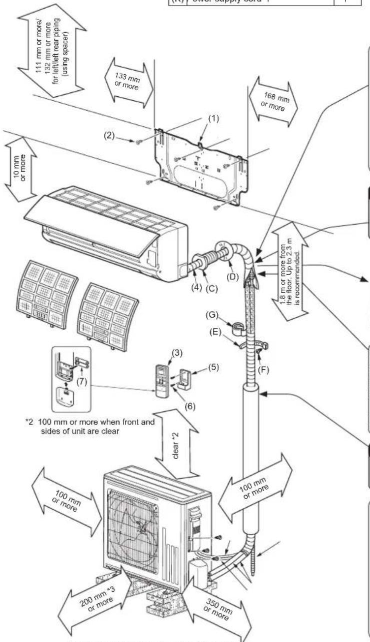
ACCESSORIES
Check the following parts before installation.
| (1) | installation plate | 1 |
| (2) | Installation plate fixing screw 4 × 25 mm | 5 |
| (3) | Wireless remote controller | 1 |
| (4) | Felt tape (For left or left-rear piping) | 1 |
| (5) | Remote controller holder | 1 |
| (6) | Fixing screw for (5) 3.5 × 16 mm (Black) | 2 |
| (7) | Battery (AAA) for (3) | 2 |
(8) Drain socket 1
PARTS TO BE PROVIDED AT YOUR SITE
| (A) | Indoor/outdoor unit connecting wire*1 | 1 |
| (B) | Extension pipe 1 | |
| (C) | Wall hole sleeve 1 | |
| (D) | Wall hole cover 1 | |
| (E) | Pipe fixing band 2 to 5 | |
| (F) | Fixing screw for (E) 4 × 20 mm 2 to 5 | |
| (G) | Piping tape | 1 |
| (H) | Putty | 1 |
| (I) | Drain hose(or soft PVC hose, 15 mm inner diameter or hard PVC pipe VP16) | 1 or 2 |
| (J) | Refrigeration oil | 1 |
| (K) | Power supply cord*1 | 1 |
Note:
*1 Place indoor/outdoor unit connecting wire (A) and power supply cord (K) at least 1 m away from the TV antenna wire.
*3 When any 2 sides of left, right and rear of unit are clear
Appearance of the outdoor unit may differ from some models.
IMPORTANT NOTES
- Units should be installed by licensed contractor according to local code requirements.
- To comply with the requirements of Australian standard AS/NZS 3000 electrical installations (wiring rules), the electrical wiring required between the indoor and outdoor units must be installed by a licenced electrical contractor.
- Check that cabling will not be subject to wear, corrosion, excessive pressure, vibration, sharp edges or any other adverse environmental effects. The check shall also take into account the effects of aging or continual vibration from sources such as compressors or fans.
Be sure to use wall hole sleeve (C) to prevent indoor/outdoor connecting wire (A) from contacting metal parts in the wall and to prevent damage by rodents in case the wall is hollow.
Indoor unit Wall hole sleeve (C)
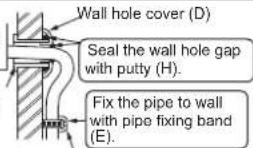
Cut off the extra length
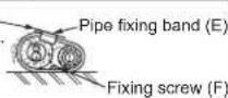
WARNING
To avoid risk of fire, flare connection should be installed outdoors. Reusable mechanical connectors and flared joints are not allowed indoors.
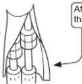
After the leak test, apply insulating material tightly so that there is no gap.
When the piping is to be attached to a wall containing metals (tin plated) or metal netting, use a chemically treated wooden piece 20 mm or thicker between the wall and the piping or wrap 7 to 8 turns of insulation vinyl tape around the piping.
To use existing piping, perform COOL operation for 30 minutes and pump down before removing the old air conditioner. Remake flare according to the dimension for new refrigerant.
WARNING
To avoid risk of fire, embed or protect the refrigerant piping. External damage on the refrigerant piping can be cause of fire.
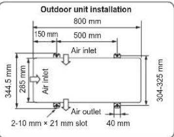
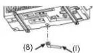
Drain piping for outdoor unit
- Provide drain piping before indoor and outdoor piping connection.
- Connect drain hose (I) I.D. 15 mm as shown in the illustration.
- Make sure to provide drain piping with a downhill grade for easy drain flow.
Note:
Install the unit horizontally.
Do not use drain socket (8) in cold regions. Drain may freeze and make the fan stop.
The outdoor unit produces condensate during the heating operation.
Select the installation place to ensure to prevent the outdoor unit and/or the grounds from being wet by drain water or damaged by frozen drain water.
2. INDOOR UNIT INSTALLATION
2-1. FIXING OF INSTALLATION PLATE
- Find a structural material (such as a stud) in the wall and fix installation plate (1) horizontally by tightening the fixing screws (2) firmly.
- To prevent installation plate (1) from vibrating, be sure to install the fixing screws in the holes indicated in the illustration. For added support, fixing screws may also be installed in other holes.
- When the knockout is removed, apply vinyl tape to the knockout edges to prevent damaging the wires.
- When bolts recessed in the concrete wall are to be utilized, secure installation plate (1) using 11 × 20 · 11 × 26 oval hole (450 mm pitch).
- If the recessed bolt is too long, change it for a shorter one available in the market.
2-2. WALL HOLE DRILLING
1) Determine the wall hole position.
2) Drill a 75 mm hole. The outdoor side should be 5 to 7 mm lower than the indoor side.
3) Insert wall hole sleeve (C).
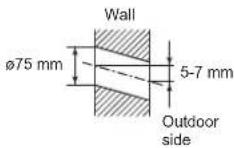
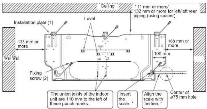
* Same for left hole.
2-3. CONNECTING WIRES FOR INDOOR UNIT
You can connect indoor/outdoor lead wire without removing the front panel.
1) Open the front panel.
2) Remove VA clamp.
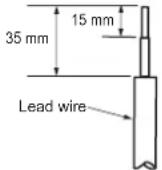
3) Pass indoor/outdoor unit connecting wire (A) from the back of the indoor unit and process the end of the wire.
4) Loosen terminal screw, and connect first the earth wire, then indoor/outdoor unit connecting wire (A) to the terminal block. Be careful not to make mis-wiring. Fix the wire to the terminal block securely so that no part of its core is appeared, and no external force is conveyed to the connecting section of the terminal block.
5) Firmly tighten the terminal screws to prevent them from loosening. After tightening, pull the wires lightly to confirm that they do not move.
6) Secure indoor/outdoor unit connecting wire (A) the earth wire with the VA clamp. Never fail to hook the right claw of the VA clamp. Attach the VA clamp securely.
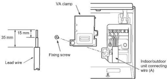
- For future servicing, give extra length to the connecting wires.
• Make earth wire a little longer than others. (More than 60 mm)
- Do not fold the excess wire, or cram it into small space. Take caution not to damage the wires.
- Be sure to attach each screw to its correspondent terminal when securing the cord and/or the wire to the terminal block. Note: Do not place the wires between the indoor unit and the installation plate (1). Damaged wire could cause heat generation or fire.
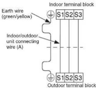
- Place the drain hose below the refrigerant piping.
• Make sure that the drain hose is not heaved or snaked.
- Do not pull the hose when applying the tape.
- When the drain hose passes the room, be sure to wrap insulation material (obtainable at a store) around it.
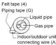
Rear, right, or downward piping
1) Put the refrigerant piping and the drain hose together, then firmly apply piping tape (G) from the end.
2) Insert the piping and the drain hose into the wall hole sleeve (C), and hook the upper part of the indoor unit on the installation plate (1).
3) Check if the indoor unit is hooked securely on the installation plate (1) by moving the unit to left and right.
4) Thrust the lower part of the indoor unit into the installation plate (1).
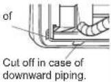
Cut off in case of right piping.
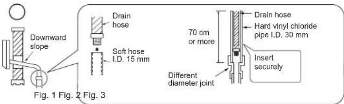
Drain Piping
- If the extension drain hose has to pass through a room, be sure to wrap it with commercially sold insulation.
- The drain hose should point downward for easy drain flow. (Fig. 1)
- If the drain hose provided with the indoor unit is too short, connect it with drain hose (I) that should be provided at your site. (Fig. 2)
- When connecting the drain hose to the hard vinyl chloride pipe, be sure to insert it securely into the pipe. (Fig. 3)
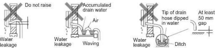
Do not make drain piping as shown below.
Left or left-rear piping
Note:
Be sure to reattach the drain hose and the drain cap in case of left or left-rear piping. Otherwise, it could cause drops of water to drip down from the drain hose.
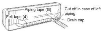
1) Put the refrigerant piping and the drain hose together, then firmly apply felt tape (4) from the end.
Felt tape (4) overlap width should be 1/3 the tape width. Use a bandage stopper at the end of felt tape (4).
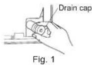
2) Pull out the drain cap at the rear right of the indoor unit. (Fig. 1)
- Hold the convex section at the end and pull the drain cap.
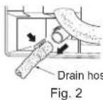
3) Pull out the drain hose at the rear left of the indoor unit. (Fig. 2)
- Hold the claw marked by the arrows and pull out the drain hose forward.
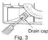
4) Put the drain cap into the section to which the drain hose is to be attached at the rear of the indoor unit. (Fig. 3)
- Insert not sharp-edged tools such as screwdrivers into the hole at the end of the cap and insert the cap fully into the drain pan.
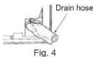
5) Insert the drain hose fully into the drain pan at the rear right of the indoor unit. (Fig. 4)
- Check if the hose is hooked securely to the projection of its inserting part at the drain pan.
6) Insert the drain hose into wall hole sleeve (C), and hook the upper part of indoor unit on installation plate (1). Then, move the indoor unit completely to the left in order to make placing the piping in the back space of the unit easier.
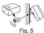
7) Cut out a piece of cardboard from the shipping box, roll it up, hook it onto the back rib, and use it as a spacer to lift the indoor unit. (Fig. 5)
8) Connect the refrigerant piping with the extension pipe (B).
9) Thrust the lower part of the indoor unit into the installation plate (1).
3. OUTDOOR UNIT INSTALLATION
3-1. CONNECTING WIRES FOR OUTDOOR UNIT
1) Open the service panel.
2) Loosen terminal screw, and connect indoor/outdoor unit connecting wire (A) from the indoor unit correctly on the terminal block. Be careful not to make mis-wiring. Fix the wire to the terminal block securely so that no part of its core is appeared, and no external force is conveyed to the connecting section of the terminal block.
3) Firmly tighten the terminal screws to prevent them from loosening. After tightening, pull the wires lightly to confirm that they do not move.
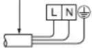
4) Connect power supply cord (K).
5) Fix indoor/outdoor unit connecting wire (A) and power supply cord (K) with the cord clamp.
6) Close the service panel securely.
Power supply cord (K)
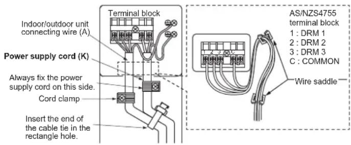
This unit has demand response capability which is compliant with AS/NZS 4755.3.1.
To activate this function, you need to make a contract with remote agents such as electric supply company, then this unit should be connected to Demand response enabling devise (DRED). For further information, consult your dealer. This unit supports
3 Demand Response Modes (DRMs): DRM1, DRM2 and DRM3.
CAUTION
- To prevent malfunction caused by noise, route the cord connecting this unit to DRED and the power supply cord as parallel as possible.
- Do not connect the demand control transmission cable to the terminal block for power supply.
- Do not pull, extremely bend or apply strong pressure on the wire to prevent failure.
- Do not screw DRED to outdoor unit.
- Do not put DRED in outdoor unit.
- Secure electrical wiring above clamp.
- Do not get DRED wire caught in the service panel.
• Make earth wire a little longer than others. (More than 100 mm)
- For future servicing, give extra length to the connecting wires.
- Be sure to attach each screw to its correspondent terminal when securing the cord and/or the wire to the terminal block.
3-2. FLARING WORK
1) Cut the copper pipe correctly with pipe cutter. (Fig. 1, 2)
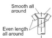
2) Completely remove all burrs from the cut cross section of pipe. (Fig. 3)
- Put the end of the copper pipe to downward direction as you remove burrs in order to avoid to let burrs drop in the piping.
3) Remove flare nuts attached to indoor and outdoor units, then put them on pipe having completed burr removal. (Not possible to put them on after flaring work.)
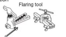
4) Flaring work (Fig. 4, 5). Firmly hold copper pipe in the dimension shown in the table. Select A mm from the table according to the tool you use.
5) Check
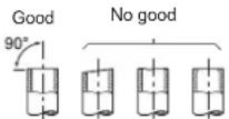
• Compare the flared work with Fig. 6.
- If flare is noted to be defective, cut off the flared section and do flaring work again.

Copper pipe
Fig. 1
Tilted Uneven Burred Fig. 2
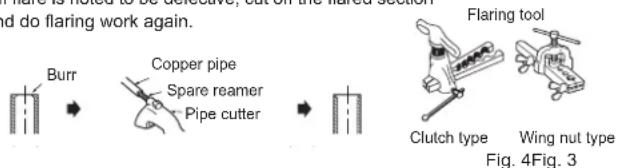
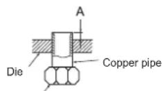
Fig. 5

Inside is shining without any scratches.
Fig. 6
| Pipe diameter (mm) | Nut (mm) | A (mm) Tightening torque |
| Clutch type tool for R32,R410A | Clutch type tool for R22 | Wing nut type tool for R22 | N·m kgf·cm |
| ø 6.35 (1/4") 17 | | 41.2 350 to 0 to 0.5 1 | 420 0 to 1.5 | 1.5 to 2.0 | 13.7 to 17.7 | 140 to 180 |
| ø 9.52 (3/8") 22 | 34.3 to | | |
| ø12.7 (1/2") 26 | | 2.0 to 2.5 | 49.0 to 56.4 | 500 to 575 |
| ø15.88 (5/8") 29 | 73.5 to | 78.4 750 to | 800 | | |
3-3. PIPE CONNECTION
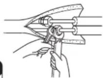
- Fasten flare nut with a torque wrench as specified in the table.
- When fastened too light, flare nut may break after a long period and cause refrigerant leakage.
- Be sure to wrap insulation around the piping. Direct contact with the bare piping may result in burns or frostbite.
Indoor unit connection
Connect both liquid and gas pipings to indoor unit.
- Apply a thin coat of refrigeration oil (J) on the flared ends of the pipes. Do not apply refrigeration oil on screw threads. Excessive tightening torque will result in damage on the screw.
- For connection, first align the center, then tighten the first 3 to 4 turns of flare nut by hand.
- Use tightening torque table above as a guideline for indoor unit side union joint section, and tighten using two wrenches. Excessive tightening damages the flare section.
WARNING
To avoid risk of fire, flare connection should be installed outdoors.
Reusable mechanical connectors and flared joints are not allowed indoors.
When connecting the refrigerant piping by brazing, rather than using flare connections, complete all brazing prior to connecting indoor unit to outdoor unit.
Outdoor unit connection
Connect pipes to stop valve pipe joint of the outdoor unit in the same manner applied for indoor unit.
- For tightening, use a torque wrench or spanner and use the same tightening torque applied for indoor unit.
WARNING
When installing the unit, securely connect the refrigerant pipes before starting the compressor.
3-4. INSULATION AND TAPING
1) Cover piping joints with pipe cover.
2) For outdoor unit side, surely insulate every piping including valves.
3) Using piping tape (G), apply taping starting from the entry of outdoor unit.
1) Cover piping joints with pipe cover.
2) For outdoor unit side, surely insulate every piping including valves.
3) Using piping tape (G), apply taping starting from the entry of outdoor unit.
- Stop the end of piping tape (G) with tape (with adhesive agent attached).
- When piping have to be arranged through above ceiling, closet or where the temperature and humidity are high, wind additional commercially sold insulation to prevent condensation.
- Stop the end of piping tape (G) with tape (with adhesive agent attached).
- When piping have to be arranged through above ceiling, closet or where the temperature and humidity are high, wind additional commercially sold insulation to prevent condensation.
3-4. INSULATION AND TAPING
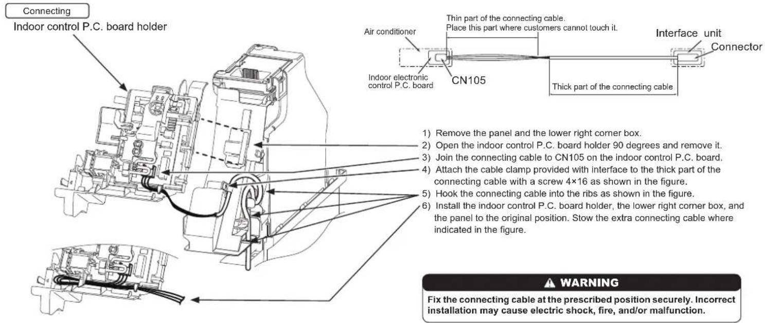
3-5. CONNECTING THE INTERFACE/CONNECTOR CABLE TO THE AIR CONDITIONER
- Connect the INTERFACE/CONNECTOR CABLE to the Indoor electronic control P.C. board of the air conditioner with the connecting cable.
- Cutting or extending the connecting cable of the INTERFACE/CONNECTOR CABLE results in defects in connecting.
Do not bundle the connecting cable together with power supply cord, indoor/outdoor connecting wire, and/or earth wire. Keep as much distance as possible between the connecting cable and those wires.
- The thin part of the connecting cable should be stored and placed where customers cannot touch it.
4. PURGING PROCEDURES, LEAK TEST, AND TEST RUN
4-1. PURGING PROCEDURES AND LEAK TEST
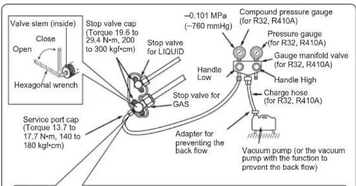
1) Remove service port cap of stop valve on the side of the outdoor unit gas pipe. (The stop valves are fully closed and covered in caps in initial state.)
2) Connect gauge manifold valve and vacuum pump to service port of stop valve on the gas pipe side of the outdoor unit.
Precautions when using the control valve
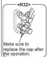
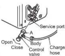
When attaching the control valve to the service port, valve core may deform or loosen if excess pressure is applied. This may cause gas leak.
When attaching the control valve to the service port, make sure that the valve core is in closed position, and then tighten part A. Do not tighten part A or turn the body when valve core is in open position.
3) Run the vacuum pump. (Vacuumize until 500 microns is achieved.)
4) Check the vacuum with gauge manifold valve, then close gauge manifold valve, and stop the vacuum pump.
5) Leave as it is for one or two minutes. Make sure pointer gauge manifold valve remains in the same position. Confirm that pressure gauge shows -0.101 MPa [Gauge] (-760 mmHg).
6) Remove gauge manifold valve quickly from service port of stop valve.
WARNING
To avoid risk of fire, make sure that there are no flammable hazards or ignition risks before opening the stop valves.
7) After refrigerant pipes are connected and evacuated, fully open the valve stem of all stop valves on both sides of gas pipe and liquid pipe by the hexagonal wrench. If the valve stem hits the stopper, do not turn it any further.
8) Refer to 1-3., and charge the prescribed amount of refrigerant if needed. Be sure to charge slowly with liquid refrigerant. Otherwise, composition of the refrigerant in the system may be changed and affect performance of the air conditioner.
9) Tighten cap of service port to obtain the initial status.
10) Leak test
4-2. TEST RUN
1) Insert power supply plug into the power outlet and/or turn on the breaker. Check that all LED lamps are not lit. If they are blinking, check that the horizontal vane is installed correctly. Refer to operating instructions for details.
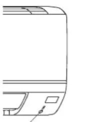
2) Press the E.O. SW once for COOL, and twice for HEAT operation. Test run will be performed for 30 minutes. If the upper lamp of the operation indicator blinks every 0.5 seconds, inspect the indoor/outdoor unit connecting wire (A) for miswiring. After the test run, emergency mode (set temperature 24^ C) will start.
3) To stop operation, press the E.O. SW several times until all LED lamps turn off. Refer to operating instructions for details.
natural_image
Line drawing of a device rear panel with buttons and a small square on the side (no text or symbols)
Emergency operation switch (E.O. SW)
Checking the remote (infrared) signal reception
Press the OFF/ON button on the remote controller (3) and check that an electronic sound is heard from the indoor unit. Press the OFF/ON button again to turn the air conditioner off.
- Once the compressor stops, the restart preventive device operates so the compressor will not operate for 3 minutes to protect the air conditioner.
4-3. AUTO RESTART FUNCTION
This product is equipped with an auto restart function. When the power supply is stopped during operation, such as during blackouts, the function automatically starts operation in the previous setting once the power supply is resumed. (Refer to the operating instructions for details.)
Caution:
- After test run or remote signal reception check, turn off the unit with the E.O. SW or the remote controller before turning off the power supply. Not doing so will cause the unit to start operation automatically when power supply is resumed.
To the user
- After installing the unit, make sure to explain the user about auto restart function.
- If auto restart function is unnecessary, it can be deactivated. Consult the service representative to deactivate the function. Refer to the service manual for details.
4-4. EXPLANATION TO THE USER
- Using the OPERATING INSTRUCTIONS, explain to the user how to use the air conditioner (how to use the remote controller, how to remove the air filters, how to remove or put the remote controller in the remote controller holder, how to clean, precautions for operation, etc.).
- Recommend the user to read the OPERATING INSTRUCTIONS carefully.
5. RELOCATION AND MAINTENANCE
5-1. REMOVING AND INSTALLING THE PANEL ASSEMBLY 5-3. PUMPING DOWN
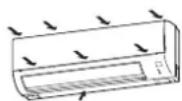
Removal procedure
1) Remove the front panel.
2) Remove the 3 screws which fix the panel assembly.
3) Remove the panel assembly. Be sure to remove its bottom end first.
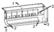
Installation procedure
1) Install the panel assembly following the removal procedure in reverse.
2) Be sure to press the positions as indicated by the arrows in order to attach the assembly completely to the unit.
* Do not hold the A part when installing/removing or carrying the panel, or the panel might be damaged.
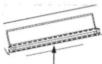
A part : lower part of air outlet of the panel
5-2. REMOVING THE INDOOR UNIT
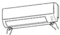
Remove the bottom of the indoor unit from the installation plate.
When releasing the corner part, release both left and right bottom corner part of indoor unit and pull it downward and forward as shown in the figure on the right.
When relocating or disposing of the air conditioner, pump down the system following the procedure below so that no refrigerant is released into the atmosphere.
1) Connect the gauge manifold valve to the service port of the stop valve on the gas pipe side of the outdoor unit.
2) Fully close the stop valve on the liquid pipe side of the outdoor unit.
3) Close the stop valve on the gas pipe side of the outdoor unit almost completely so that it can be easily closed fully when the pressure gauge shows 0 MPa [Gauge] (0 kgf/cm²).
4) Start the emergency COOL operation.
To start the emergency operation in COOL mode, disconnect the power supply plug and/or turn off the breaker. After 15 seconds, connect the power supply plug and/or turn on the breaker, and then press the E.O. SW once. (The emergency COOL operation can be performed continuously for up to 30 minutes.)
5) Fully close the stop valve on the gas pipe side of the outdoor unit when the pressure gauge shows 0.05 to 0MPa [Gauge] (approx. 0.5 to 0kgf/cm^2 ).
6) Stop the emergency COOL operation.
Press the E.O. SW several times until all LED lamps turn off. Refer to operating instructions for details.
WARNING
When pumping down the refrigerant, stop the compressor before disconnecting the refrigerant pipes. The compressor may burst if air etc. get into it.


