
VPC16-WP-4 - Video Conferencing System VIEWSONIC - Free user manual and instructions
Find the device manual for free VPC16-WP-4 VIEWSONIC in PDF.


| Product Type | Video Conferencing System |
| Brand | ViewSonic |
| Model | VPC16-WP-4 |
| Dimensions (W x H x D) | 220 x 60 x 80 mm |
| Weight | 1.2 kg |
| Power Supply | 12V DC, 2A (AC adapter included) |
| Camera Resolution | 1080p Full HD, 120° wide angle |
| Microphone | Dual omnidirectional, 3m pick-up range |
| Speaker | 5W full range |
| Connectivity | HDMI, USB-C, USB-A, RJ45 Ethernet, Wi-Fi 802.11ac, Bluetooth 4.2 |
| Compatible Platforms | Zoom, Microsoft Teams, Skype, Google Meet |
| Compatible Operating Systems | Windows, macOS, Android, iOS |
| Control | Remote control, touch buttons |
| Mounting | Tripod mount, wall mountable (bracket optional) |
| Special Features | Auto framing, noise reduction, plug-and-play |
| Maintenance | Clean with soft dry cloth; avoid liquids |
| Safety Certifications | CE, FCC |
| Spare Parts Availability | Visit ViewSonic support website for accessories |
Frequently Asked Questions - VPC16-WP-4 VIEWSONIC
User questions about VPC16-WP-4 VIEWSONIC
0 question about this device. Answer the ones you know or ask your own.
Ask a new question about this device
Download the instructions for your Video Conferencing System in PDF format for free! Find your manual VPC16-WP-4 - VIEWSONIC and take your electronic device back in hand. On this page are published all the documents necessary for the use of your device. VPC16-WP-4 by VIEWSONIC.
USER MANUAL VPC16-WP-4 VIEWSONIC
Slot in PC module VPC16-WP_VPC17-WP (for IFP50 series)
Quick Start Guide
Model No. VS17668
Compliance Information
NOTE: This section addresses all connected requirements and statements regarding regulations. Confirmed corresponding applications shall refer to nameplate labels and relevant markings on unit.
FCC Compliance Statement
This device complies with part 15 of FCC Rules. Operation is subject to the following two conditions: (1) this device may not cause harmful interference, and (2) this device must accept any interference received, including interference that may cause undesired operation.
This equipment has been tested and found to comply with the limits for a Class B digital device, pursuant to part 15 of the FCC Rules. These limits are designed to provide reasonable protection against harmful interference in a residential installation. This equipment generates, uses, and can radiate radio frequency energy, and if not installed and used in accordance with the instructions, may cause harmful interference to radio communications. However, there is no guarantee that interference will not occur in a particular installation. If this equipment does cause harmful interference to radio or television reception, which can be determined by turning the equipment off and on, the user is encouraged to try to correct the interference by one or more of the following measures:
• Reorient or relocate the receiving antenna.
- Increase the separation between the equipment and receiver.
- Connect the equipment into an outlet on a circuit different from that to which the receiver is connected.
- Consult the dealer or an experienced radio/TV technician for help.
Warning: You are cautioned that changes or modifications not expressly approved by the party responsible for compliance could void your authority to operate the equipment.
Industry Canada Statement
CAN ICES-3 (B)/NMB-3(B)
Contains FCC ID: PD99260NG
IC ID: 1000M-9260NG
CE Conformity for European Countries
CE The device complies with the EMC Directive 2014/30/EU and Low Voltage Directive 2014/35/EU and Radio Equipment Directive (RED) 2014/53/EU.
Following information is only for EU-member states:
The mark shown to the right is in compliance with the Waste Electrical and Electronic Equipment Directive 2012/19/EU (WEEE). The mark indicates the requirement NOT to dispose the equipment as unsorted municipal waste, but use the return and collection systems according to local law. In all EU member states, operation of 5150-5350MHz is restricted to indoor use only. This device should be installed and operated with a minimum distance of 20cm between the radiator and your body.

Indian Restriction of Hazardous Substances
Restriction on Hazardous Substances statement (India) This product complies with the “India E-waste Rule 2011” and prohibits use of lead, mercury, hexavalent chromium, polybrominated biphenyls or polybrominated diphenyl ethers in concentrations exceeding 0.1 weight % and 0.01 weight % for cadmium, except for the exemptions set in Schedule 2 of the Rule.
Declaration of RoHS2 Compliance
This product has been designed and manufactured in compliance with Directive 2011/65/EU of the European Parliament and the Council on restriction of the use of certain hazardous substances in electrical and electronic equipment (RoHS2 Directive) and is deemed to comply with the maximum concentration values issued by the European Technical Adaptation Committee (TAC) as shown below:
| Substance | Proposed Maximum Concentration | Actual Concentration |
| Lead (Pb) 0.1% < 0.1% | ||
| Mercury (Hg) 0.1% < 0.1% | ||
| Cadmium (Cd) 0.01% < 0.01% | ||
| Hexavalent Chromium ( Cr^6+ ) 0.1% < 0.1% | ||
| Polybrominated biphenyls (PBB) 0.1% < 0.1% | ||
| Polybrominated diphenyl ethers (PBDE) 0.1% < 0.1% |
**Certain components of products as stated above are exempted under the Annex III of the RoHS2 Directives as noted below:
Examples of exempted components are:
- Lead in glass of cathode ray tubes
- Lead in glass of fluorescent tubes not exceeding 0.2% by weight
- Lead as an alloying element in aluminium containing up to 0.4% lead by weight
- Copper alloy containing up to 4% lead by weight
- Lead in high melting temperature type solders (i.e. lead-based alloys containing 85% by weight or more lead)
- Electrical and electronic components containing lead in a glass or ceramic other than dielectric ceramic in capacitors, e.g. piezoelectronic devices, or in a glass or ceramic matrix compound.
- Lead as an alloying element in steel for machining purposes and in galvanized steel containing up to 0.35% lead by weight.
- Lead in dielectric ceramic in capacitors for a rated voltage of 125V AC or 250V DC or higher.
- Cadmium and its compounds in electrical contacts.
1. Interface
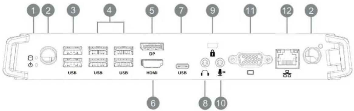
| Item Description | |
| 1 | Working indicator light |
| 2 | WIFI antenna interface |
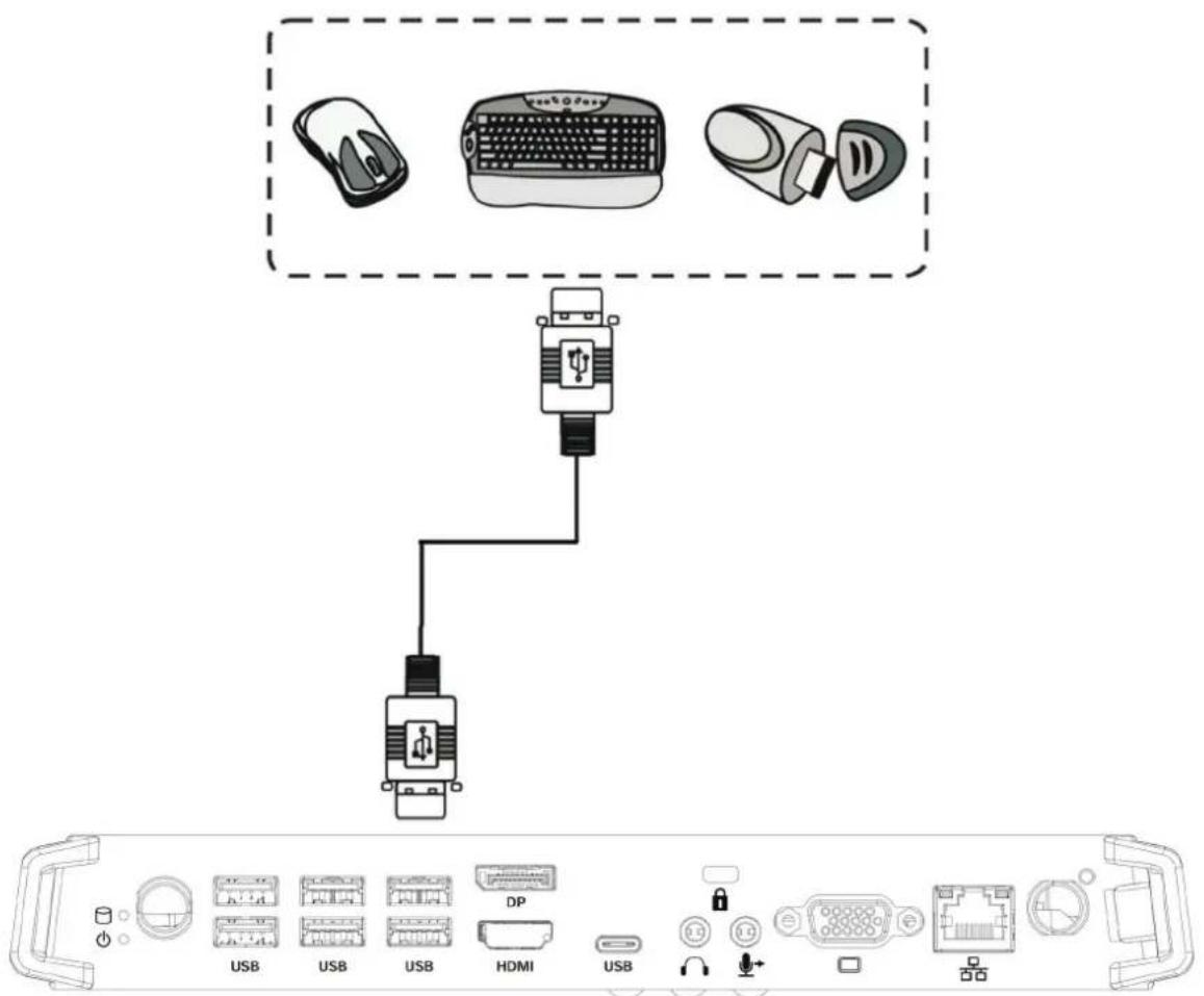
| 3 | USB 2.0 interface |
| 4 | USB 3.0 interface |
| 5 | Connect the display to a DisplayPort connector |
| 6 | Connected to device with HDMI input function |
| 7 | USB type C interface |
| 8 | Connects the device to headphones or speakers |
| 9 | Anti-theft lock |
| 10 | Connects to a microphone |
| 11 | Connects the display to a VGA-IN connector |
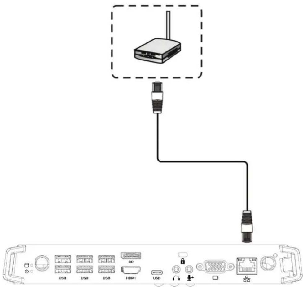
| 12 | Standard RJ45 (10M/100M/1G) Internet connection interface (This network port is only used for PC) |
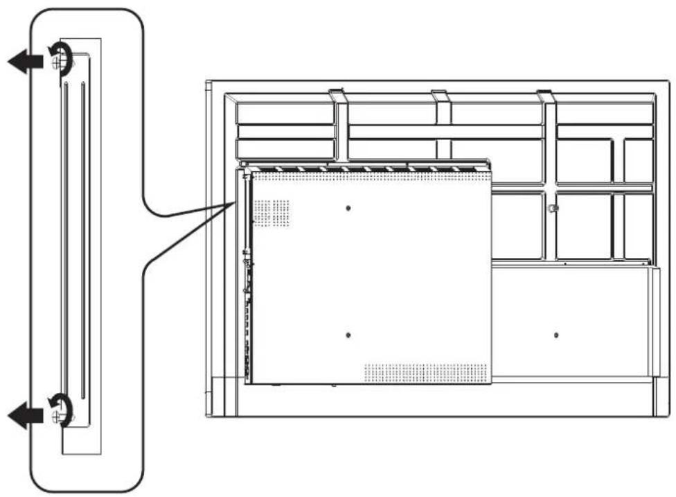
2. Installation
2-1
natural_image
Technical line drawing of a mechanical or architectural component with internal layout and directional arrows (no text or symbols)2-2
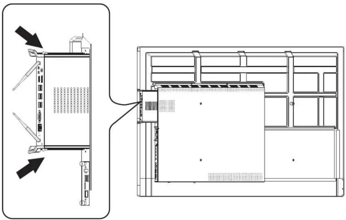
natural_image
Technical line drawing of a server rack unit with front and side views, showing internal components and mounting hardware (no text or labels)2-3
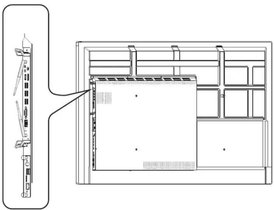
natural_image
Technical line drawing of a server rack with front panel and internal storage unit (no text or symbols)- Internet Connection
4. Input Selection
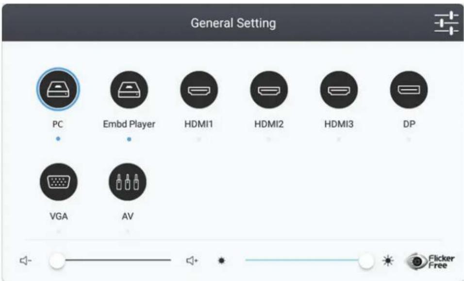
- Press INPUT button on remote control to display the input setting menu, then press DOWN to enter the input source menu.
- Press DOWN / UP / LEFT/ RIGHT to select PC.
- Press Enter button on remote control or click with touch pen to select the input source.
-
Press EXIT key on remote control or click blank area outside menu with touch pen to quit the on-screen menu.
-
USB Connection
1 Introduction
This document provides a quick reference for some of the basic features of the Intel Unite ^® client application.
Refer to the Intel Unite® Solution Deployment Guide for more information about the server, hub, and client setup.
Refer to the Intel Unite® Solution User Guide for details about using the hub and client.
This document assumes that the hub and client are already set up with the hub application running, the client application installed, and the client registered with the Intel Unite® solution server.
2 Connect
Figure 2.1 Hub Screen
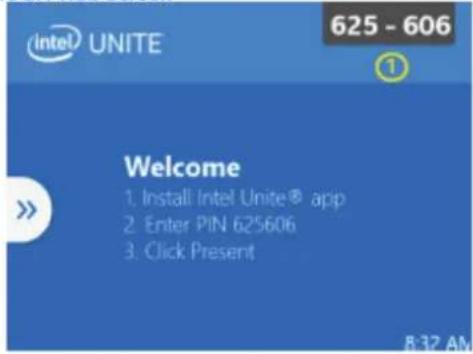
On the Hub
- Take note of the PIN displayed on the hub screen.
Figure 2.2 Intel Unite® Application Icon
On the Client
- Launch the Intel Unite® client application.
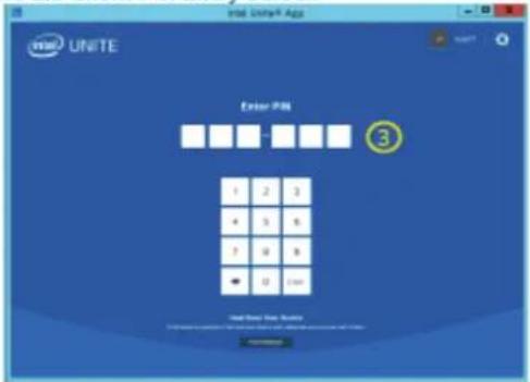
Figure 2.3 Client PIN Entry Screen
On the Client
- Enter the PIN in the client application.
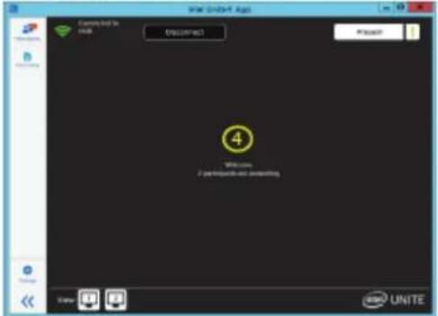
Figure 2.4 Client Connected Screen
On the Client
- This is the view of the client after connecting to the hub.
3 Present
Figure 3.1 Client Connected Screen
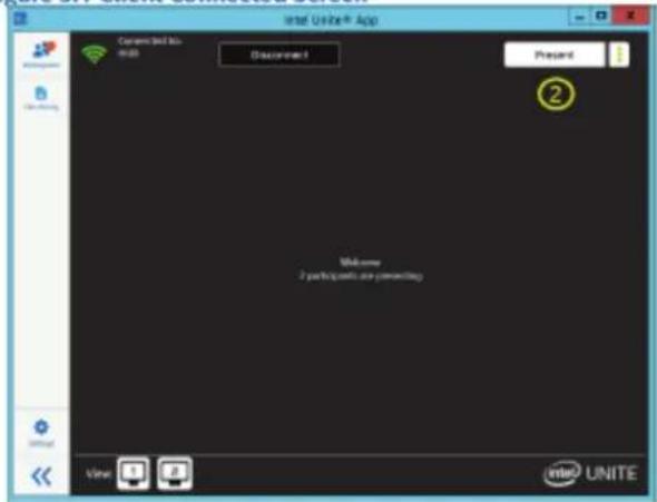
- Connect to the hub. Refer to Connect, page 6.
- Click the Present button.
Figure 3.2 Client Presenting Screen
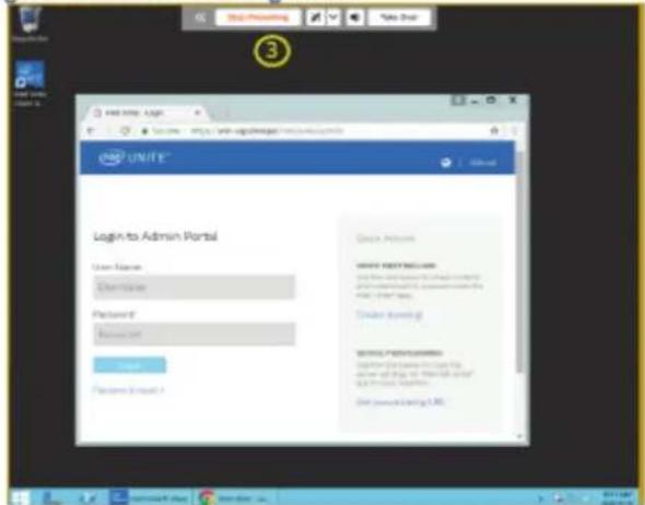
- The client is now presenting the screen, indicated by an orange border and a control panel at the top.
Note: The Take Over button is only available when multiple users are presenting to the same hub display.
3.1 Present Screen
Figure 3.1.1 Client Connected Screen
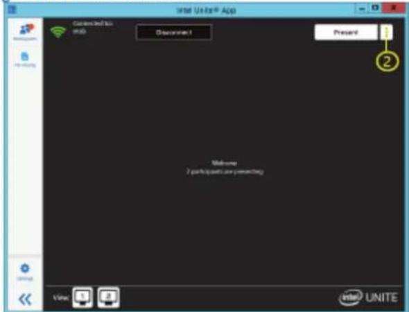
- Connect to the hub. Refer to Connect for details.
- Click the more options icon next to the Present button.
Figure 3.1.2 Client Present Screen Options
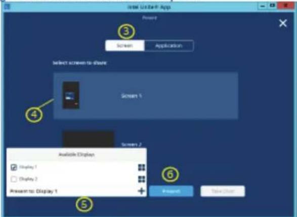
- Select Screen.
- Choose a screen to display.
- Choose the hub display to present to.
- Click the Present button.
Figure 3.1.3 Client Presenting Screen
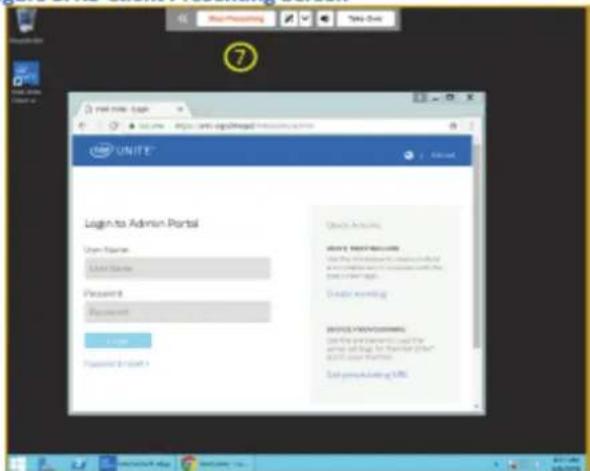
- The client is now presenting the screen, as indicated by the control panel at the top and the yellow border around the screen.
Note: The Take Over button is only available when multiple users are presenting to the same hub display.
 | Control bar options:A. Minimize panelB. Stop presentingC. Enable/Disable annotateD. Advanced annotation optionsE. Mute/Unmute audio during video playbackF. Take Over presentingG. Enable/Disable Screen ControlNotes:The Take Over button is only available when multiple users are presenting to the same hub display.Screen Control button appears when the hub display is touch capable. |
3.2 Present Application
Figure 3.2.1 Client Connected Screen
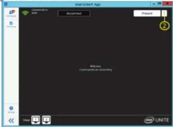
- Connect to the hub. Refer to Connect for details.
- Click the more options icon next to the Present button.
Figure 3.2.2 Client Present Application Option
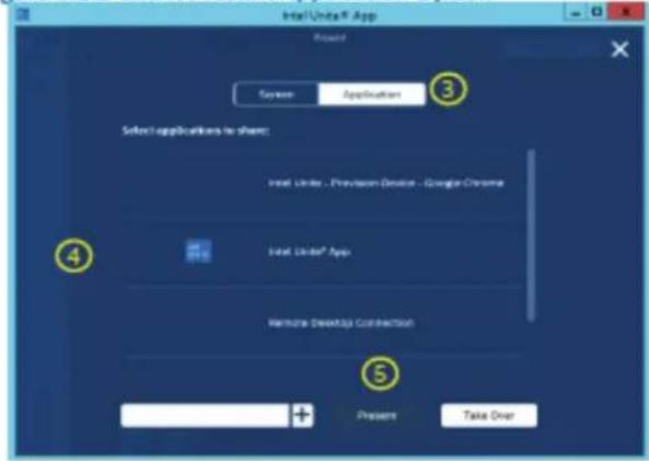
- Select Application.
- Choose an application to display.
- Click the Present button.
Figure 3.2.3 Client Presenting Application Screen
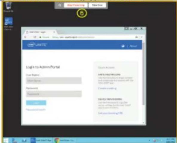
- The client is now presenting the application, as indicated by the control panel at the top and the orange border around the application. When presenting an application, the control bar will look different from the one shown when presenting a screen.
Note: The Take Over button is only available when multiple users are presenting to the same hub display.
4 Viewing
Figure 4.1 Client Connected Screen
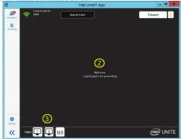
- Connect to the hub. Refer to Connect for details.
- Another user starts presenting.
- Click the user whose presentation you want to view. The view differs if the presenter is sharing a screen or sharing an application.
Figure 4.2 Client Viewing – Present Screen
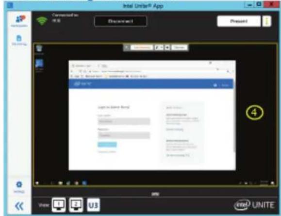
- Figure 4.2 shows the client viewing a presentation.
5 Annotation
Figure 5.1 Client Presenting Screen
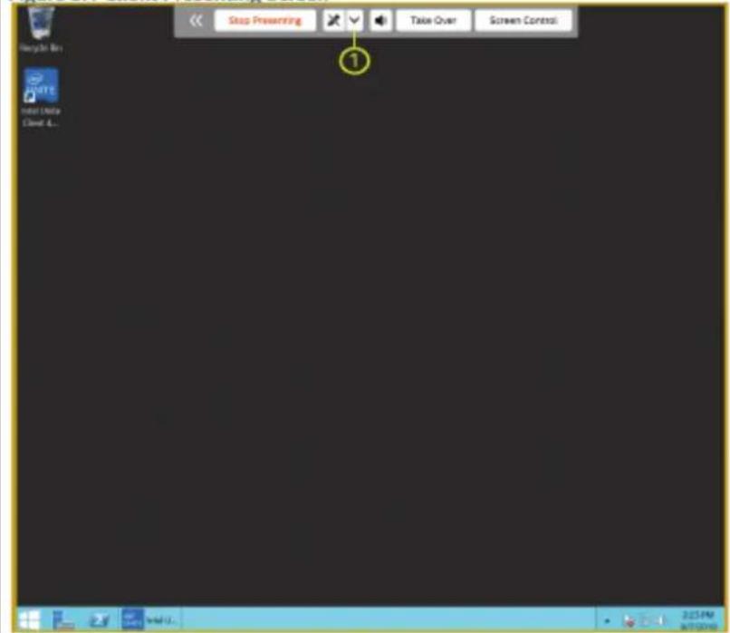
- While presenting, click the down arrow next to the pencil icon. Refer to Present Screen for details. An orange border will appear when presenting.
Notes:
The Take Over button is only available when multiple users are presenting to the same hub display.
The Screen Control button appears when the hub display is touch capable.
Figure 5.2 Client Presenting Screen with Annotation Control Panel Open
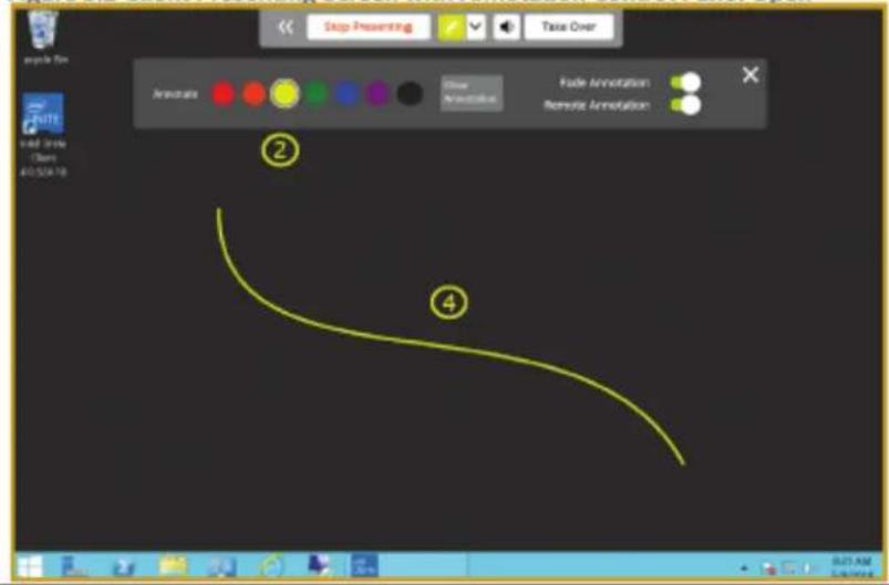
- Select an ink color.
- Click the pencil icon. The icon changes color to match the selected ink color.
- Click or touch and drag to annotate.
Note: Annotations are compatible with touch-enabled screens (touch and drag) as well as mouse devices (click and drag).
6 File Sharing
Figure 6.1 Client Connected Screen
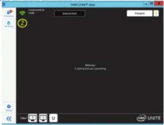
- Connect to the hub. Refer to Connect for details.
- Click the File Sharing icon.
Figure 6.2 Client File Sharing Screen
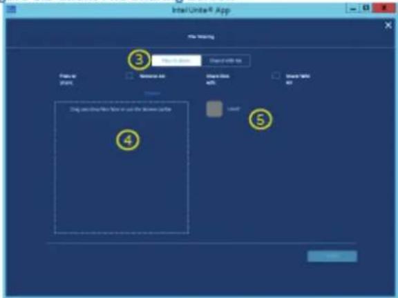
- Select Files to share.
- Drag and drop files to be shared.
- Select the User to share files with.
Figure 6.3 Client File Sharing Screen with Files Selected
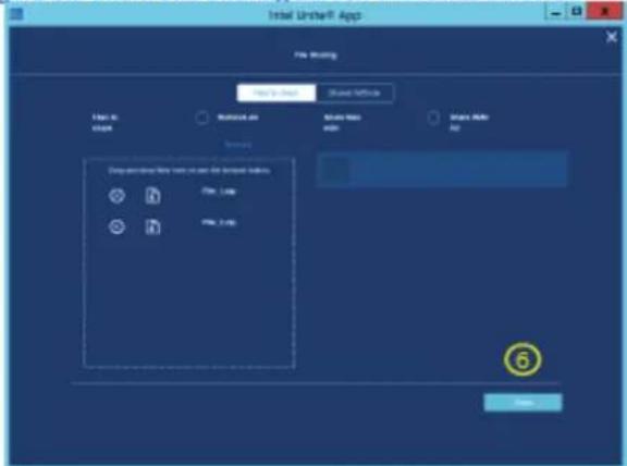
- Click the Share button.
7 Receive Files
Figure 7.1 Client Connected Screen
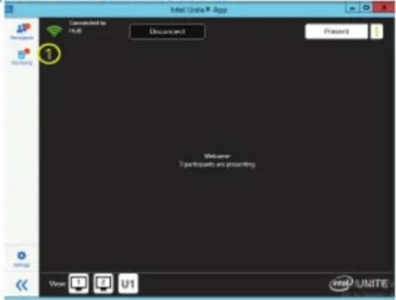
Example: Another user has shared files with this user.
- Click the File Sharing icon. Notice the orange circle with a number in it next to the File Sharing icon. This number is the number of files being shared with the user.
Figure 7.2 Client File Sharing Screen
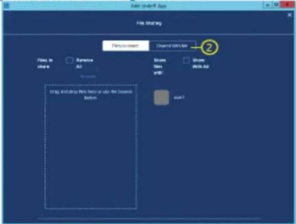
- Select Shared With Me.
Figure 7.3 Client Shared with Me Screen
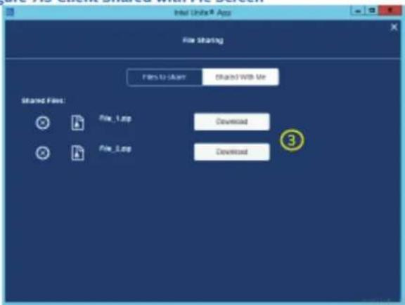
- Click the Download button to download the file.
8 Lock Meeting
Figure 8.1 Client Connected Screen
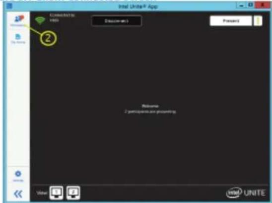
- Connect to the hub. Refer to Connect for details.
- Click the Participants icon.
Figure 8.2 Client Participants Screen
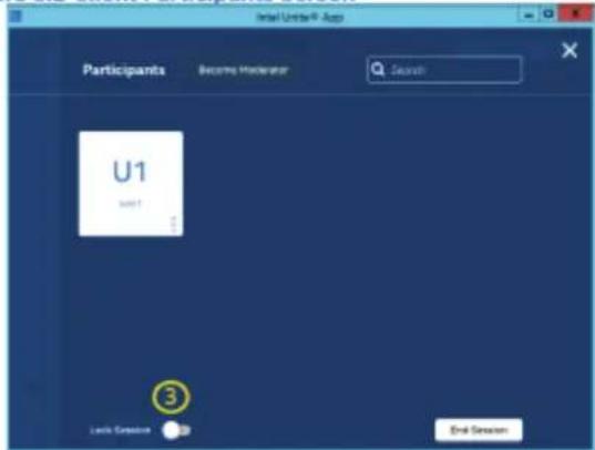
- Click the Lock Session switch to lock the meeting. The lock will turn from gray to green. When the meeting is locked, no additional users can join the meeting.
9 Disconnect User
Figure 9.1 Client Connected Screen
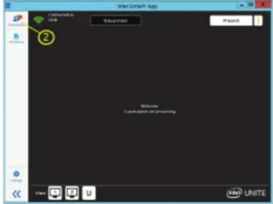
- Connect to the hub. Refer to Connect for details.
- Click the Participants icon.
Figure 9.2 Client Participant Screen
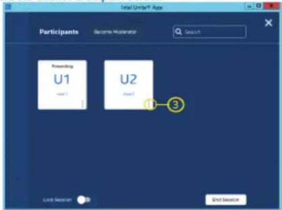
- Click the three dots at the bottom-right corner of a user to open the user actions.
Figure 9.3 Client Participant Screen – User Options
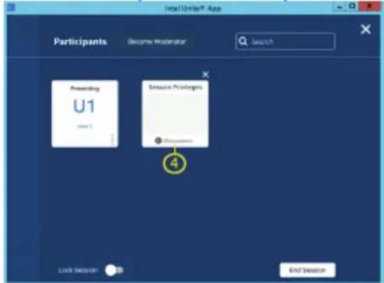
- Click Disconnect to disconnect the user.
6. Specifications
| IO ports | 1 x Display Port1 x HDMI1 x VGA1 x LAN2 x USB 2.0 (5V/0.5A)4 x USB 3.0 (5V/0.9A)1 x USB type C1 x Earphone1 x Microphone | |
| Power 100V-240V AC 50/60HZ | ||
| Operation Conditions | Temperature Humidity Altitude | 32°F to 113°F (0°C to 45°C)10% ~ 90% non-condensing0 meter to +5000 meters above sea level |
| Storage Conditions | Temperature Humidity Altitude | -4°F to 140°F (-20°C to 60°C)10% ~ 90% non-condensing0 meter to +5000 meters above sea level |
| Dimensions Physical(mm) 246.1 x 263.4 x 32.2 | ||
| Weight Physical(kg) 1.95 | ||
| Power consumption 95W | ||
| Frequency Range and Output Power (Max.) | 2402 to 2480 MHz(BT) 2.0 dBm2402 to 2480 MHz(LE) 3.73 dBm2412 to 2472 MHz 17.41 dBm5150 to 5250 MHz 18.94 dBm5250 to 5350 MHz 18.94 dBm5470 to 5725 MHz 18.94 dBm | |
7. Customer Support
For technical support or product service, see the table below or contact your reseller.
NOTE: You will need the product serial number.
| Country/Region | Website | T= TelephoneC = CHAT ONLINE | |
| AustraliaNew Zealand | www.viewsonic.com.au | AUS= 1800 880 818NZ= 0800 008 822 | service@au.viewsonic.com |
| Canada www.viewsonic.com | T = 1-866-463-4775 | service.ca@viewsonic.com | |
| Europe | www.viewsoniceurope.com | http://www.viewsoniceurope.com/eu/support/call-desk/ | |
| Hong Kong www.hk.viewsonic.com | T= 852 3102 2900 | service@hk.viewsonic.com | |
| India www.in.viewsonic.com | T= 1800 419 0959 | service@in.viewsonic.com | |
| Korea ap.viewsonic.com | T= 080 333 2131 | service@kr.viewsonic.com | |
| Latin America www.viewsonic.com | la/ | C=http://www.viewsonic.com/la/soporte/servicio-tecnico | soporte@viewsonic.com |
| Macau www.hk.viewsonic.com | T= 853-2840-3687 | service@hk.viewsonic.com | |
| Middle East ap.viewsonic.com | me/ Contact your reseller | service@ap.viewsonic.com | |
| Puerto Rico & Virgin Islands | www.viewsonic.com | T= 1-800-688-6688 (English)C= http://www.viewsonic.com/la/soporte/servicio-tecnico | service.us@viewsonic.comsoporte@viewsonic.com |
| Singapore/Malaysia/Thailand | www.ap.viewsonic.com T= | 65 6461 6044 | service@sg.viewsonic.com |
| South Africa | ap.viewsonic.com/za/ | Contact your reseller | service@ap.viewsonic.com |
| United States | www.viewsonic.com T = 1-800-688-6688 | service.us@viewsonic.com | |

natural_image
Three colorful bird illustrations perched on a branch against a red background (no text or symbols)ViewSonic®
- Compliance Information
- FCC Compliance Statement
- Industry Canada Statement
- CE Conformity for European Countries
- Following information is only for EU-member states:
- Indian Restriction of Hazardous Substances
- Declaration of RoHS2 Compliance
- Interface
- Installation
- Input Selection
- Introduction
- Connect
- On the Hub
- On the Client
- Present
- Present Screen
- Present Application
- Viewing
- Annotation
- Notes:
- File Sharing
- Receive Files
- Lock Meeting
- Disconnect User
- Specifications
- Customer Support
Brand : VIEWSONIC
Model : VPC16-WP-4
Category : Video Conferencing System