
Self Checkout - Barcode scanners Elgin - Free user manual and instructions
Find the device manual for free Self Checkout Elgin in PDF.


| Product Type | Self-checkout scanner/scale with integrated barcode reader and weighing scale |
| Dimensions | Model-dependent: Short (approx. 12.6 x 10.2 x 7.1 in), Medium (approx. 16.5 x 10.2 x 7.1 in), Long (approx. 20.5 x 10.2 x 7.1 in) |
| Weight | Approximately 15–25 lbs depending on model |
| Power Requirements | 100–240 VAC, 50–60 Hz, autosensing; AC/DC adapter included |
| Scanning Technology | 360° omni-directional laser scanning; reads 1D and 2D barcodes including UPC/EAN, Code 39, Code 128, DataBar, and more |
| Scale Capacity | 30 lb (0.01 lb increments) or 15 kg (0.005 kg increments); overload up to 150 lb (68 kg) without damage |
| EAS Deactivation | Optional built-in EAS antenna for deactivating security labels (Sensormatic compatible) |
| Interfaces | RS-232, IBM, USB (OEM), Keyboard Wedge; supports multiple POS systems |
| Warm-Up Time | 15 minutes after power-up; 60 minutes if unit has been moved from cold storage to reach thermal equilibrium |
| Maintenance | Clean horizontal and vertical windows twice daily with mild glass cleaner; clear debris chutes daily |
| Safety | Laser Class II; requires proper grounding and clean power supply |
| Spare Parts | Replaceable vertical and horizontal scan windows, L-platter, cables, AC/DC adapter |
| Repair Information | Contact Datalogic technical support or authorized reseller; unit must be returned in original packaging for service |
| General Information | Manufactured by Datalogic USA, Inc.; Product Reference Guide included (542 pages) |
Frequently Asked Questions - Self Checkout Elgin
User questions about Self Checkout Elgin
0 question about this device. Answer the ones you know or ask your own.
Ask a new question about this device
Download the instructions for your Barcode scanners in PDF format for free! Find your manual Self Checkout - Elgin and take your electronic device back in hand. On this page are published all the documents necessary for the use of your device. Self Checkout by Elgin.
USER MANUAL Self Checkout Elgin
natural_image
Exterior view of two modern industrial robotic devices with transparent internal compartments and metal frame (no visible text or symbols)
Product Reference Guide
Datalogic USA, Inc.
959 Terry Street
Eugene, OR 97402
USA
Telephone: (541) 683-5700
Fax: (541) 345-7140
© 2006–2017 Datalogic S.p.A. and its Group companies
An Unpublished Work - All rights reserved. No part of the contents of this documentation or the procedures described therein may be reproduced or transmitted in any form or by any means without prior written permission of Datalogic S.p.A. or its subsidiaries or affiliates ("Datalogic" or 'Datalogic USA, Inc."). Owners of Datalogic products are hereby granted a non-exclusive, revocable license to reproduce and transmit this documentation for the purchaser's own internal business purposes. Purchaser shall not remove or alter any proprietary notices, including copyright notices, contained in this documentation and shall ensure that all notices appear on any reproductions of the documentation.
Should future revisions of this manual be published, you can acquire printed versions by contacting your Datalogic representative. Electronic versions may either be downloadable from the Datalogic website (www.datalogic.com) or provided on appropriate media. If you visit our website and would like to make comments or suggestions about this or other Datalogic publications, please let us know via the "Contact Datalogic" page.
Disclaimer
Datalogic has taken reasonable measures to provide information in this manual that is complete and accurate, however, Datalogic reserves the right to change any specification at any time without prior notice.
Datalogic and the Datalogic logo are registered trademarks of Datalogic S.p.A. in many countries, including the U.S.A. and the E.U. All other brand and product names may be trademarks of Datalogic S.p.A. or of Datalogic Group companies, registered in many countries, including the U.S. and the E.U.
All other brand and product names may be trademarks of their respective owners.
Magellan is a trademark of Datalogic S.p.A. or of Datalogic Group companies, registered in many countries, including the U.S. and the E.U.
Patents
See www.patents.datalogic.com for patent list.
Table of Contents
Chapter 1. INTRODUCTION.... 1
Manual Overview 1
How to Use This Manual 2
Technical Support 4
Datalogic Website Support 4
Reseller Technical Support 4
Telephone Technical Support 4
Scanner and Scanner/Scale Features 5
Connections 6
Physical Parameters 7
Scanning 7
Deactivating EAS Labels 7
Weighing 7
Warm-Up Time 8
Electrical Specifications 9
Bar Codes Supported 10
Retail Codes 10
Industrial Codes 10
Dual Bar Codes for Japan (2 label read) 10
Chapter 2. SITE PREPARATION AND INSTALLATION.... 11
Models 12
Pre-Installation Considerations 13
Checkstand Design 14
Scanner Installation 15
Scanner Maintenance 15
References 15
Scanner Usage 16
Site Preparation Overview 16
Ventilation and Spacing 18
Service Access 20
Power Installation 20
Grounding 20
Checkstand Preparation 21
Liquid Spills and Moisture 22
Counter Cutout 22
Checkstand Mounting 30
Checkstand Vibration 30
Installation Overview 30
Unpacking 31
Operational Verification 32
Diagnostic Modes 34
Cables & Connections 36
Remote Scale Display Placement/Installation 37
Lighting Considerations 37
Viewing Angle 38
Remote Display Cabling 39
Placing and Installing the Remote Scale Display 39
Changing Weighing Modes 42
Set-Up & Installation 42
Set-up 42
Installation 44
System Power-Up Recap 48
Chapter 3. OPERATION AND MAINTENANCE.... 51
Scanning Items 51
Deactivating Security Labels 53
Proper Weighing Technique 53
Operational Controls 54
Operational Modes 54
Power-Up/Selftest & Pre-Operation 54
Operating Mode 56
Additional Functions 57
Programming 57
Diagnostic Mode 57
Scanner and Scale Reset 57
Scale Adjustments 58
Operational Maintenance 60
Vertical Scan Window Replacement 61
Horizontal Scan Window Replacement (WRG) 64
Chapter 4. PROBLEM ISOLATION ...... 67
Diagnostic Procedures 68
Error Codes 69
Scale Error Reporting 72
Flowcharts 73
Chapter 5. CALIBRATION....81
Description of Calibration Sequence 82
Motion Test 83
Automatic Zero Tracking Test 83
Preparing the Scanner/Scale for Calibration 84
Calibrating the Scale (Pounds & Kilograms) 84
Calibration Verification (U.S. Pounds) 87
Increasing-Load Test (Phase 1) 87
Shift Test 88
Increasing- Load Test (Phase 2) 89
Blanking Test 89
Decreasing-Load Test 90
Return to Zero Test 90
Calibration Verification (Kilograms) 91
Increasing-Load Test (Phase 1) 91
Shift Test (Metric) 92
Increasing- Load Test (Phase 2) 93
Blanking Test 93
Decreasing-Load Test 94
Return to Zero Test 94
Chapter 6. PROGRAMMING ...... 95
Introduction to Label Programming 95
Understanding the Basics 95
Integrating the Scanner With Your Host System 96
Customizing Your Scanner's Operation 96
Programming Overview 98
Programming via Handheld Device 98
What Is Programming Mode? 99
Entering and Exiting Programming Mode. 99
Programming Session 100
LED and Beeper Indicators 104
If You Make a Mistake.... 104
Return to Factory Settings 104
Test Mode 105
General Scanner Features 106
Scanner Button Options 106
Double Read Timeout 108
Laser Timeout 110
Motor Timeout 112
Label Gone Timeout 115
Auxiliary Port Mode 118
Auxiliary Port Baud Rate 120
Laser Failure Mode 124
Productivity Index Reporting (PIR)/Cashier Training (CT) 125
Indication Features 126
Green LED Idle State 126
Power-up Beep Control 127
Good Read Beep Control 128
Good Read Beep Frequency 129
Good Read Beep Length 131
Good Read Beep Volume 132
Good Read When to Indicate 135
Scale Features 137
Scale Enable 137
Scale Enforced Zero Return 138
Scale Interface Type 141
Scale Calibration Notification 143
Scale Intercharacter Delay 144
Remote Display — Enable/Disable 145
EAS Features 146
EAS Active State 146
EAS Timeout 147
Interface Related Features 148
Interface Type 148
Number of Host Transmission Buffers 169
AIM ID 170
Label ID Control 172
Global Prefix 175
Global Suffix 177
Case Conversion 179
IBM Features 181
IBM Interface Options 181
IBM Number of Host Resets 182
IBM Scale Address 183
IBM Transmit Labels in Code 39 Format .... 185
IBM Label Slicing Control 186
IBM Maximum Label Slice Length 187
OEM USB Scanner Device Type 188
RS-232 Features 189
RS-232 Baud Rate 189
RS-232 Number of Data Bits 193
RS-232 Number of Stop Bits 194
RS-232 Parity 195
RS-232 Hardware Control 197
RS-232 Intercharacter Delay 200
RS-232 Software Flow Control 201
RS-232 Host Echo 202
RS-232 Host Echo Quiet Interval 203
RS-232 Ignore Host Commands 204
RS-232 TTL 205
RS-232 TTL Invert 206
RS-232 ICL DC1 Character Delay Enable 207
RS-232 Team POS ICL Scale 208
RS-232 Beep on ASCII BEL 209
RS-232 Beep After Weigh 210
RS-232 Beep on Not on File 211
RS-232 ACK NAK Enable 212
RS-232 ACK Character 214
RS-232 NAK Character 215
RS-232 Retry on ACK NAK Timeout 216
RS-232 ACK NAK Timeout Value 217
RS-232 ACK NAK Retry Count 218
RS-232 ACK NAK Error Handling 219
RS-232 Indicate Transmission Failure 221
Single Cable RS-232 Options 222
Single Cable RS-232 Scanner Only Protocol 223
Single Cable RS-232 Stale Weight Timeout 224
Single Cable RS-232 Scale — Transmit Weight Digits 226
Single Cable Manufacturer Extensions 227
Single Cable Pacesetter Plus Enable 228
Single Cable RS-232 RTS CTS Selection 229
Single Cable RS-232 Use BCC 232
Single Cable RS-232 Use ACK/NAK 233
Single Cable RS-232 Use STX 234
Set Single Cable RS-232 STX Character 235
Set Single Cable RS-232 ETX Character 236
Keyboard Wedge/USB Keyboard Features 237
Keyboard Interface — Keyboard Layout 237
Keyboard Interface Quiet Interval 246
Keyboard Interface Caps Lock State 247
Keyboard Interface — Keyboard Simulation 249
Keyboard Interface — Control Characters 250
Keyboard Interface — Intercharacter Delay 252
Symbology Programming 253
Coupon Control 253
UPC-A Enable 255
UPC-A Number System Character Transmission 256
UPC-A Check Character Transmission 257
Expand UPC-A to EAN-13 258
UPC-A Label ID 259
UPC-A 2-Digit Supplemental Label ID 260
UPC-A 5-Digit Supplemental Label ID 261
UPC-A 128 Supplemental Label ID 262
UPC-A Minimum Reads 263
UPC-E Enable 265
UPC-E Number System Character Transmission 266
UPC-E Check Character Transmission 267
Expand UPC-E to UPC-A 268
Expand UPC-E to EAN-13 269
UPC-E Label ID 270
UPC-E 2-Digit Supplemental Label ID 271
UPC-E 5-Digit Supplemental Label ID 272
UPC-E 128 Supplemental Label ID 273
UPC-E Minimum Reads 274
EAN-13 Enable 276
EAN-13 First Character Transmission 277
EAN-13 Check Character Transmission 278
EAN-13 ISBN Conversion Enable 279
EAN 13 Label ID 280
EAN-13 2-Digit Supplemental Label ID 281
EAN-13 5-Digit Supplemental Label ID 282
EAN-13 128 Supplemental Label ID 283
EAN-13 Minimum Reads 284
Bookland Label ID 286
EAN-8 Enable 287
EAN-8 Check Character Transmission 288
Expand EAN-8 to EAN-13 289
EAN-8/JAN-8 Guard Insertion 290
EAN-8/JAN-8 Guard Substitution 291
EAN-8/JAN-8 Both Guards Substitution 292
EAN-8 Stitch Exact Label Halves 293
EAN-8 Stitch Unlike Label Halves 294
EAN 8 Label ID 295
EAN-8 2-Digit Supplemental Label ID 296
EAN-8 5-Digit Supplemental Label ID 297
EAN-8 128 Supplemental Label ID 298
EAN-8 Decoding Levels 299
EAN-8 Minimum Reads 302
EAN-8 Minimum Segment Length 304
Other UPC/EAN Options 310
Price Weight Check 311
In-Store Label Minimum Reads 314
Enable EAN Two Label 316
EAN Two Label Combined Transmission 317
UPC/EAN Guard Insertion 318
UPC/EAN Stitch Exact Label Halves 319
UPC/EAN Stitch Unlike Label Halves 320
UPC/EAN Character Reconstruction 321
EAN Two Label Minimum Reads 322
UPC/EAN Correlation 324
UPC/EAN Minimum Segment Length 325
Addons 331
Addon Timer 335
2-Digit Add-ons Minimum Reads 336
5-Digit Add-ons Minimum Reads 338
Code 128 Add-ons Minimum Reads 340
GTIN Enable 342
GTIN Label ID 343
GTIN 2-Digit Supplemental Label ID 344
GTIN 5-Digit Supplemental Label ID 345
GTIN Code 128 Supplemental Label ID 346
DataBar Omnidirectional Enable 347
DataBar Omnidirectional/EAN-128 Emulation 348
DataBar Omnidirectional Label ID 349
DataBar Omnidirectional Minimum Reads 350
DataBar Expanded Enable 352
DataBar Expanded EAN-128 Emulation 353
DataBar Expanded Label ID 354
DataBar Expanded Length Control 355
DataBar Expanded Length 1 356
DataBar Expanded Length 2 357
DataBar Expanded Minimum Reads 358
Code 39 Enable 360
Code 39 Start Stop Character Transmission .... 361
Code 39 Check Character Calculation ...... 362
Code 39 Check Character Transmission .... 363
Code 39 Full ASCII 364
Code 39 Label ID 365
Code 39 Require Quiet Zones 366
Code 39 Length Control .... 367
Code 39 Length 1 368
Code 39 Length 2 369
Code 39 Correlation 370
Code 39 Stitching .... 371
Code 39 Minimum Reads ....372
Pharmacode 39 Enable 374
Pharmacode 39 Start Stop Character Transmission 375
Pharmacode 39 Check Character Transmission .... 376
Pharmacode 39 Label ID 377
Code 128 Enable 378
Code 128 Transmit Function Characters .... 379
Convert Code 128 to Code 39 .... 380
Code 128 Label ID 381
Code 128 Length Control 382
Code 128 Length 1 383
Code 128 Length 2 384
Code 128 Correlation ....385
Code 128 Stitching 386
Code 128 Minimum Reads ....387
EAN-128 Enable 389
EAN-128 Label ID 390
Interleaved 2 of 5 (1 2 of 5) Enable ....391
12 of 5 Check Character Calculation ......392
12 of 5 Check Character Transmission 393
12 of 5 Label ID 394
12 of 5 Length Control 395
| 2 of 5 Length 1 ....396
12 of 5 Length 2 ....397
12 of 5 Correlation 398
12 of 5 Stitching 399
12 of 5 Minimum Reads ....400
Standard 2 of 5 (Std 2 of 5) Enable ....402
Standard 2 of 5 Check Character Calculation ....403
Standard 2 of 5 Check Character Transmission 404
Standard 2 of 5 Label ID ....405
Standard 2 of 5 Length Control 406
Standard 2 of 5 Length 1 ....407
Standard 2 of 5 Length 2 408
Standard 2 of 5 Correlation ....409
Standard 2 of 5 Stitching 410
Standard 2 of 5 Minimum Reads ....411
Codabar Enable 413
Codabar Start Stop Character Transmission 414
Codabar Start Stop Character Set 415
Codabar Start Stop Character Match 417
Codabar Check Character Calculation 418
Codabar Check Character Transmission 419
Codabar Label ID 420
Codabar Require Quiet Zones 421
Codabar Length Control 422
Codabar Length 1 423
Codabar Length 2 424
Codabar Correlation 425
Codabar Stitching 426
Codabar Minimum Reads 427
Code 93 Enable 429
Code 93 Label ID 430
Code 93 Length Control 431
Code 93 Length 1 432
Code 93 Length 2 433
Code 93 Correlation ....434
Code 93 Stitching 435
Code 93 Minimum Reads 436
MSI/Plessey Enable 438
MSI/Plessey Check Character Calculation 439
MSI/Plessey Number of Check Characters 440
MSI/Plessey Check Character Transmission 441
MSI/Plessey Label ID 442
MSI/Plessey Length Control 443
MSI/Plessey Length 1 444
MSI/Plessey Length 2 445
MSI/Plessey Correlation 446
MSI/Plessey Stitching 447
MSI/Plessey Minimum Reads 448
Appendix A. LED/BEEPER INDICATIONS & CONTROLS.... 451
Controls and Indicators 451
LED and Beeper Indications 452
Volume/Tone Push Button 454
Scale Zero Push Button 456
Calibration Switch 457
Appendix B. CABLE INFORMATION.... 459
Introduction 459
General Specifications 459
RS-232 Cable Pinout 460
Scanner 460
Scale 461
IBM Cable Pinout 462
Scanner and Scale 462
OEM USB Cable Pinout 463
Scanner and Scale 463
Auxiliary Port 464
External Handheld Input 464
Power Cable 465
Connector Hardware 465
Remote Display 466
Connector Hardware 466
EAS Comm Port (Sensormatic ^® systems ONLY) 467
EAS Deactivator Control Box Connection 467
Appendix C. KEYPAD.... 469
Appendix D. HOST COMMANDS.... 477
Accepting Commands from an RS-232 Scanner Host 477
Appendix E. KEYBOARD FUNCTION KEY MAPPINGS 479
Keyboard Model Cross Reference 479
Appendix F. FACTORY DEFAULTS.... 489
Appendix G. HANDHELD DATA FORMAT REQUIREMENTS.... 515
Handheld Data Format Requirements General 515
Datalogic Handheld Data Format Requirements 516
AIM Formats 523

Chapter 1 Introduction
This Product Reference Guide contains comprehensive instructions on scanner or scanner/scale installation. Either model may be termed “scanner” for the purpose of simplicity in this manual. Also included are feature configuration using special programming feature bar code labels and advanced user information as described in the following chapter descriptions.
Manual Overview
Chapter 1, Introduction, outlines the manual's contents, details features and specifications, provides regulatory and safety information, and lists the symbologies (bar code types) the scanner will read.
Chapter 2, Site Preparation and Installation, presents physical dimensions for the scanner or scanner/scale and popular accessories, and provides counter preparation and installation procedures. Cable routing, connection and testing are additionally detailed in this chapter.
Chapter 3, Operation and Maintenance, contains use and maintenance instructions; providing details about operator controls, programming and diagnostic modes, scale “zeroing” and calibration. Scanner and scale routine maintenance is also outlined in this chapter.
Chapter 4, Problem Isolation, outlines the three scanner/scale test modes: Selftest, Operational Tests and Diagnostic Tests. Procedures for system problem and troubleshooting flowcharts to aid in problem resolution are also presented in this chapter.
Chapter 5, Calibration, explains scale calibration and verification procedures, including procedures for calibrating the scale in pounds as well as kilograms.
Chapter 6, Programming, highlights the function(s) of each programmable feature and provides a dedicated set of bar codes for configuring scanner and scanner/scale features. This chapter is organized by the categories: General Features, Interface Related Features and Symbology Related Features.
Appendix A, LED/Beeper Indications & Controls, contains tables describing the various functions and indications of the scanner/scale control panel features.
Appendix B, Cable Information, references wire requirements, connector specifications and pinout details for product cabling.
Appendix C, Keypad, is a set of bar codes representing the digits and characters required to enter extended programming data needed during certain programming sessions.
Appendix D, Host Commands, furnishes a partial listing of available host commands that can be used with a compatible host interface.
Appendix E, Keyboard Function Key Mappings, summarizes the keyboard models, their defined protocol, scancode set, and some unique features. Other tables in this chapter provide the function key maps associated with each of the scancode sets.
Appendix F, Factory Defaults, lists factory default programmable settings for common interfaces.
Appendix G, Handheld Data Format Requirements, contains application notes describing the general format of data accepted by the scanner through the auxiliary port as transmitted from a handheld scanner.
How to Use This Manual
Reference the first chapter of this manual for a general description of the product's features and an outline of the manual's contents and organization. View the remaining chapters for procedures regarding scanner or scanner/scale installation, operation, maintenance, calibration and bar code programming.
Manual Conventions
 NOTE NOTE | 'NOTE' blocks contain information that is helpful and recommended. They provide information that is critical to operations and/or procedures described in this manual. |
 | 'LEGAL NOTE' blocks indicate procedures or activities which may be regulated under law by governmental agencies. It is your responsibility to ensure compliance with the regulations that govern installation of weighing devices. |
 | 'CAUTION' blocks inform you that proper handling (adherence to the procedures described) is required to avoid damage to equipment and/or property. |
 | 'WARNING' blocks alert you to potential physical harm or injury. These statements do not include potentially fatal hazards, which would be designated as 'DANGER' blocks. Use of this product does not warrant the need for a DANGER block. |
Technical Support
Datalogic Website Support
The Datalogic website (www.datalogic.com) is the complete source for technical support and information for Datalogic products. The site offers product support, product registration, warranty information, product manuals, product tech notes, software updates, demos, and instructions for returning products for repair.
Reseller Technical Support
An excellent source for technical assistance and information is an authorized Datalogic reseller. A reseller is acquainted with specific types of businesses, application software, and computer systems and can provide individualized assistance.
Telephone Technical Support
If you do not have internet or email access, you may contact Data-logic technical support at (541) 349–8281.
Scanner and Scanner/Scale Features
Controls, indicators and other features are shown in Figure 1.
Figure 1. Scanner/Scale Features

Connections
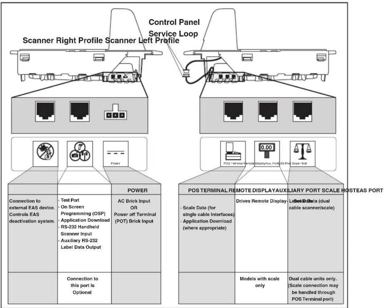
Two connector panels are located on either side of the scanner as shown in Figure 2. The appearance of these panels will vary depending upon the factory options purchased with your model. Additionally, a service “pigtail” extends from the scanner’s base to connect the control panel cable from the Bonnet area.
Figure 2. Connectors

Physical Parameters
This chapter provides specifications for performance, environmental and electrical parameters. Reference Chapter 2, Site Preparation and Installation, for physical measurements of all models and some accessories.
Scanning
The scanner has a scan zone between the two windows where the scanner projects laser light in order to scan items. Two separate projections, one from the horizontal window and one from the vertical window, combine to form a zone where bar code labels are read. Refer to Chapter 3, Scanning Items, for more information.
Deactivating EAS Labels
Deactivation of EAS (Electronic Article Surveillance) anti-theft labels is an additional function that can be performed by the scanner. More information about this feature can be referenced under the following topics:
• Chapter 3, Deactivating Security Labels
• Chapter 6, EAS Features
Weighing
Specifications for scale capacity, settling time, minimum and maximum static weight, zeroing, and warm-up time are given below. For more information regarding the topic: Proper Weighing Technique on page 53, refer to Chapter 3, Operation and Maintenance in this manual.
Rated Weight Capacity
The scale's operational weight capacity is:
• 30.00 pounds, displayed in 0.01 increments OR
• 15.000 kilograms, displayed in 0.005 increments.
Minimum Increment
The minimum weight that can be accurately measured by the scale is 0.01 lb. (0.005 kg).
Maximum Static Weight (Overload)
A maximum static weight of 150 pounds (68 kg) can be sustained by the scale without incurring damage or degrading performance.
Automatic Zero Maintenance
The scale's software constantly monitors and adjusts the Zero point as long as the deviation is within acceptable limits, while compensating for debris accumulation or removal. During power-up, the scale automatically re-zeros after verifying that all subsystems are functional. Additionally, the scale may be manually “zeroed” by pushing the Scale Zero Push Button at the bottom of the control panel.
Warm-Up Time

NOTE
There are two pertinent warm-up times that apply to the scanner or scanner/scale:
The two warm-up periods can be performed concurrently, thereby reducing the total required warm-up time to 60 minutes.
Thermal Equilibrium
When the unit is moved from a cooler temperature (such as a storage area) to a warmer environment (such as a checkstand location), 60 minutes must be allowed to acclimate the unit to ambient conditions prior to calibration or operation.
Power-up
Once installed and powered up, a warm-up time of 15 minutes must be allowed before calibrating or performing weighing operations.
User Configurable Warm-up
The user may configure the unit for a pre-programmed warm-up time that is activated every time the scanner is powered up. During this time, the scale is viewed by the POS terminal as off-line.

NOTE
Contact Technical Support on page 4 to learn more about this advanced programmable feature.
Figure 3. Environmental Specifications
| Operation | ||
| Temperature 10° to +40°C 50° to +104°F | Dust Proof Optics Cavity, IP5X | |
| Illumination Artificial Light: 0-450 Foot-candles (4,842 LUX) | Sunlight: 0-8,000 Foot-candles (86,080 LUX) | Humidity Hot / Wet 40°C / 95% RH Hot / Dry 40°C / 15% RH Cold / Dry 10°C / 1 5% RH Warm / Wet 25%C / 50% RH |
| Spill Proof (Datalogic MS-0006-13-0004) | ||
| Storage | ||
| +70°C +158F -40°C -40F Temperature -40° to +70°C -40° to +158°F |
Electrical Specifications
Before installation, always verify that the site's electrical service meets the scanner/scale's requirements. The scanner has been engineered for compatibility with most international electrical systems operating in ranges from 100 to 240VAC at 50–60 Hz. Verify that the power source will supply "clean" electrical power to the equipment; that is, it must be free of excess electrical noise.
Bar Codes Supported
The scanner can read/decode the following bar code types (symbolologies):
Retail Codes
- UPC Versions A & E with full expansion E to A, plus A and E to 13 capability
- UPC Supplementals and Add-ons (Bookland & Coupon code, UPC two character supplemental encoding and UPC five character supplemental encoding and supplemental C128) with support for conditional add-ons
- DataBar Omnidirectional (formerly RSS-14)
- DataBar Expanded (formerly RSS Expanded) maximum characters 74 numeric or 41 alpha
- DataBar Stacked Omnidirectional (formerly RSS-14 Stacked)
• EAN 8 & 13 with full expansion 8 to 13
• JAN 8 & 13 with full expansion 8 to 13
• UCC/EAN 128
• Italian Pharmacode (Code 39)
• Support GTIN
Industrial Codes
• C o d e 3 9
- Code 39 full ASCII
• Code 128 (including conversion to Code 39)
• C o d e 9 3
• Interleaved 2 of 5 (1 2 of 5)
- Standard 2 of 5
- Codabar
• MSI/Plessey
Dual Bar Codes for Japan (2 label read)

NOTE
The following qualifications apply to Dual Bar Codes for Japan:
■ Two label combined transmission
- Two label global midamble (see Chapter 6, Programming, for more details)
- Two label flag is set by selecting any 4 digits as the flag
Chapter 2
Site Preparation and Installation
This chapter provides a reference for preparing most checkstands to receive the scanner or scanner/scale. Included are physical parameters and instructions for checkstand preparation, power and ventilation considerations, cable routing information and unit installation.
Site Preparation lists all procedures necessary to prepare the checkstand. The instructions that follow, titled Checkstand Preparation on page 21, detail steps for the scanner only and scanner/scale variations that are available (shown in Figure 4) to facilitate easy installation into almost any checkstand application around the world.
Once the procedures in this chapter are complete, the scanner is ready for scanning operation ^1 ; with the exception that if a scanner/ scale was installed, calibration will be required before placing the unit into operation. You must consult the local weights and measures authority to ensure that all legal requirements are met concerning calibration and certification. Chapter 5, Calibration, contains detailed procedures for calibrating the scale in either pounds or kilograms.
Models
Scanner and scanner/scale models (reference Figure 4) are available in different lengths, allowing them to fit with little or no modification into openings cut for previously installed scanners such as Datalogic™ Magellan™ scanners, or NCR® scanner models 7820/24 and 7870. Other models are designed for applications with smaller footprint requirements.
Figure 4 provides simplified illustrations of short, medium and long models. The appearance of your unit may vary. Scanner/scale models also offer an option for a raised Produce Rail, or a flip-up Produce Bar as shown in Figure 6.
Figure 4. Model Examples

Figure 5. Flanged and Shelf Model Examples
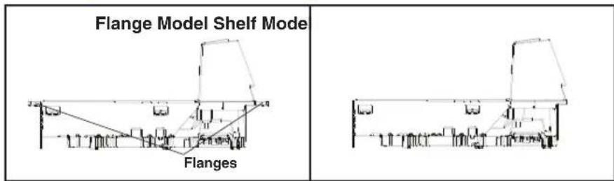
Figure 6. Produce Bar and Produce Rail

Pre-Installation Considerations
It should be noted that the scope of this manual does not encompass all factors related to worker safety and checkstand design. It does, however, offer a list of considerations that may be helpful in ensuring greater safety and productivity. Careful planning using these general guidelines should result in a more efficient, comfortable work environment.
The U.S. Bureau of Labor Statistics reports that the incidence of repetitive motion injuries has increased dramatically in recent years. Checkstand design and scanner installation and operation procedures can reduce the risk of repetitive motion injuries, but not eliminate it.
Although there are currently no formal guidelines for checkstand ergonomics, the Food Marketing Institute (FMI) and the National Institute of Occupational Safety (NIOSH) of the Department of Health and Human Services have released the reports listed at the end of these recommendations. These reports contain useful suggestions for ergonomic improvement of checkstand designs and scanner installation, maintenance and usage. Portions of the reports are summarized below. For copies of the complete reports, or to inquire about any modifications to the recommendations, contact FMI and NIOSH at the addresses listed at the end of these recommendations.
Checkstand Design
- Select a design which allows load-sharing by several muscle groups (for example designs which allow the cashier to use both hands for scanning and bagging).
- Select checkstands which deliver products to the cashier on an input belt and do not require the unloading of items from a cart. These designs put less stress on the cashiers' shoulders and back.
- Minimize the distance between the input and take-away conveyors (i.e., the distance the cashier has to reach to move the products).
- Minimize the width of the input conveyor to reduce the cashier's reach to items on the far side of the belt; use a diverter to direct products closer to the cashier.
- Select a design which encourages the cashier to slide products across the scanner rather than gripping and lifting. Make sure the horizontal surface of the scanner is flush with all surrounding surfaces.
- Choose a design which integrates the scanner and scale to eliminate extended reaches and lifts during weighing tasks.
- Provide an easily accessible bag stand at a height 13 - 17 inches (33 - 43.2 cm) lower than the top surface of the check-stand to reduce stresses to the shoulders, elbows, and risks associated with lifting products into bags.
- Do not position the bag stand between the cashier and the scanner, due to the increased reach involved.
- Position the scanner's horizontal scanning surface 34–36" (86.4 – 91.4 cm) above the floor. Maintain a minimum of five inches (12.7 cm) clearance between elbows and work surfaces.
- Provide adjustable keyboard mounting (height, tilt, and horizontal reach).
-
Position the printer, cash drawer, and other checkstand devices the cashier uses within easy reach (less than 18 inches/45.7 cm).
-
Provide adequate toe space, foot rests or rails, antifatigue mats, and where feasible, an adjustable seat or stand against which the cashiers can lean.
Scanner Installation
- Mount the horizontal surface of the scanner flush with the countertop to encourage slide scanning rather than lifting.
- Position the centerline of the scanner read area 8 - 10 inches (20.3 - 25.4 cm) from the edge of the checkstand (cashier side).
Scanner Maintenance
- Keep scanner windows clean. This will improve productivity and reduce rescans.
- Replace scanner glass when excessive scratches are evident.
References
Anonymous, 1992, “Ergonomic Improvement of Scanning Checkstand Designs”, Food Marketing Institute 800 Connecticut Ave. N.W. Washington, D.C. 20006
Grant, Katharyn A. et al., 1992, "Ergonomic Evaluation of Checkstand Designs in the Retail Food Industry", National Institute of Occupational Safety and Health 4676 Columbia Parkway Cincinnati, Ohio 45226
Scanner Usage
- Minimize handling of heavy/bulky products. Leave these items in the cart and use an alternative entry method such as key entry of short PLUs, or handheld scanning.
-
Regularly train cashiers in proper scanning methods and ergonomics principles, such as:
-
Develop a smooth fluid motion during scanning, sharing work equally between hands.
- Use the entire hand for grasping and lifting items.
- Since the scanner reads labels on all four sides plus the top and bottom, there is no need to turn a bar code toward either of the scanner windows.
- Develop efficient scanning motions, not necessarily faster hand movements. Simply slide the item across the scanner's horizontal window with as little orientation motion as necessary.
- Leave items in an upright position; do not lift and tilt.
- Learn how the scanner functions and where the scanning area is located.
- Do not favor either the vertical or horizontal window; slide items across the scanner in their natural orientations on the checkstand as much as possible.
Site Preparation Overview
Consider the following factors before installing the scanner or scanner/scale and its optional Remote Scale Display.
Ventilation Requirements — The scanner operates without the use of a ventilation fan. As long as there is adequate convective air flow and no major heat producing equipment in close proximity, the unit's housing provides adequate heat dissipation. The air temperature in the checkstand around the scanner must not exceed 104°F (40°C).
Service Access Requirements — Routine operations such as ‘zeroing’ and calibration do not require removal of the scanner from the checkstand or disassembly of the product. The installer should plan service access for the AC/DC Power Supply and cables.
Recommended Power Installation — Since the typical grocery environment includes conveyor belts and electric motors, care should be taken to ensure that the scanner has a supply of “clean” power (power without excessive electrical noise).
Counter Preparation — Since the majority of grocery checkout lanes are designed as “left-hand take away,” the counter drawings in this chapter focus on this counter design. Simply reverse the layout for a “right-hand take away” requirement. The unit scans equally well in either of these two configurations.
Liquid Drainage — Should a liquid spill occur, ensure that moisture can flow through the checkstand without pooling.
Leveling — Plan ahead and provide screws/bolts in the checkstand mounts and a leveling guide (board) to allow leveling of the scanner or scanner/scale within the counter. Use a 0.375" thick board to replicate the mounting flange on the long scanner or scanner/scale, and adjust screws or bolts until the board is flush within the counter. Use a 4.0" wide board stood on its end to adjust leveling screws/bolts in rail support applications.
Cable Routing — Placement of the scanner/scale should be planned to allow easy access to other components as well as optimize communication between the scanner, the POS terminal, the optional Remote Scale Display and any EAS peripheral equipment. Do not route interface cables near any electrical motors or other sources of electromagnetic interference.
Remote Scale Display Placement — The customer, and checker in some instances, must be able to easily view and read the Remote Scale Display. Ambient light and mounting height considerations are discussed later in this chapter.
Vertical Clearance — Provision must be made to allow adequate space above the scanner bonnet for removal and replacement of an L-shaped platter. Optimal clearance permits the platter to be grasped at its top vertical edge and lifted for removal without obstruction (such as a fixed keyboard mount or any type of enclo-
sure). Should such an enclosure be unavoidable, an alternate method of platter removal using two coins may be employed, however a minimum vertical clearance of 1.5" (3.8 cm) MUST be provided (reference Figure 7). Another consideration is that the scan zone must be kept free of obstructions such as enclosures, keyboard mounts, etc.
Figure 7. Vertical Clearance

Ventilation and Spacing
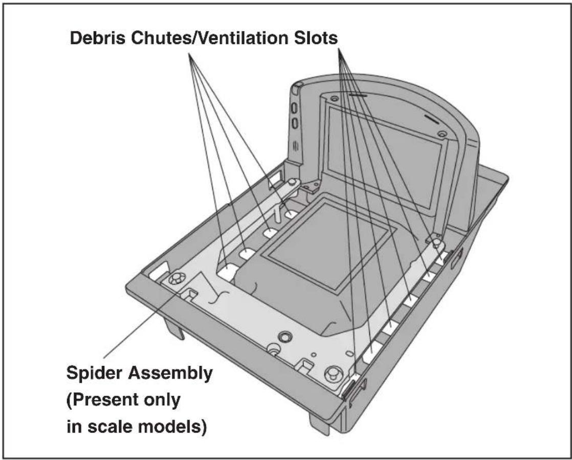
The scanner/scale's perimeter housing has been designed to provide adequate space for convective cooling and unrestricted movement of the weighing apparatus. Figure 8 shows the debris chutes and ventilation slots. The checkstand design must allow:
- The ambient air temperature inside the checkstand adjacent to the scanner must not exceed 104^ (40°C).
- A source of air that provides adequate cooling by convective air flow.

NOTE
DO NOT place the scanner in a close-fitting, fully enclosed checkstand. Provide a MINIMUM of 16 square inches (103.2 square centimeters) of air intake from below the installation for sufficient convective cooling.
If motors, conveyor belts, or other heat producing equipment are located near the scanner, forced air ventilation may be required. In most installations, a 30 cfm (.84 cmm) axial fan should provide sufficient air movement. If a ventilation fan is installed, one with a removable filter that may be washed or replaced is recommended.
Figure 8. Debris Chutes & Ventilation Slots
Service Access
The scanner and scanner/scale have been engineered to allow performance of all routine service and maintenance (such as “zeroing” and calibration) without removing the scanner from the checkstand. Additionally all cable connections made at the scanner can be connected and removed while the unit is sitting on the countertop. The installer should provide service access to all remaining cable connectors as well as the AC/DC Power Supply (if installed).
Power Installation
Plug your scanner into an electrical outlet that has been wired to meet all applicable electrical codes, laws, and regulations and has a common ground with the Point-of-Sale terminal
Grounding
The AC/DC Power Supply should have an AC outlet with a clean earth ground. If you are not sure how to verify the amount of electrical noise (interference) on the power line, ask a qualified electrician to measure the input line voltage.
Checkstand Preparation
Reference Figure 9. When performing a first time installation into a new checkstand, verify before cutting that room will be allowed for cabling, the AC/DC Power Supply, and any EAS peripheral equipment (such as controller boxes, etc.). When making the opening, take extra care to accurately cut to the correct dimensions. Mounting may require installation of support(s), countertop routing, or other such devices. Depending upon checkstand design, you may wish to install an item diverter to direct items toward the scan window. See the instructions in this manual titled “Counter Cutout” for more details concerning the location and preparation of the opening.
Figure 9. Installation Overview

Liquid Spills and Moisture
Select a checkstand design which allows fluids to flow through, and directs liquids away from any electronic equipment or storage areas.
Counter Cutout
The most important consideration when planning the counter opening for the scanner is the operator's comfortable reaching distance. The ideal, ergonomically sound installation allows items to be directed within easy reach, and a scanning area requiring no lifting or special orientation of items. If you haven't already read the information at the beginning of this chapter titled, Pre-Installation Considerations on page 13, please do so before continuing these instructions.
The symmetrical design of the scanner permits the operator to easily pass items from one hand to the other while scanning (either from right-to-left or left-to-right). With the unique 360-scan zone, scanning is accomplished in one fluid motion. The operator simply slides the item from the conveyor belt or diverter area through the scanning area and passes the item to the other hand, which in turn bags it or places it on a take-away conveyor belt. Movement should flow naturally over the surface of the scanner.
Note that the following guidelines for preparing an existing checkstand to accept a scanner, or incorporating the unit into a new checkstand design will not be accurate for all installations. Although these guidelines will suffice for most standard installations, the installer may need to make adjustments for varying counter heights and thicknesses, support design, or other checkstand limitations.
Figure 10 shows a typical "left-hand-take-away" checkstand design.
Follow these basic steps to install the unit:
- Select a position for the scanner that offers a smooth product flow which best accommodates the reaching distance of the average operator.
-
Cut the opening in the countertop. Reference Table 1 to find the cut-out dimensions for your model. Flange and shelf mount dimensions are provided for your convenience.
-
Install the AC/DC Power Supply, the Remote Scale Display cable (if Remote Display is used) and the interface cable(s) observing the following:
Interface cables (and display cable, if applicable) should be routed away from all highly inductive electrical devices, like motors and conveyor belts, and even away from the unit's power cable if possible.
Cables should be easy to remove in the event that replacement is required. A little planning now will save a lot of frustration later.
- Connect and verify all system operations.
The scanner should be installed so that leading and trailing edges of the L-Platter are flush with the countertop to enhance smooth, slide-through scanning (reference the insert in Figure 10). Keep in mind that the debris chutes on both sides of the platter provide the necessary clearance for proper scale operation if you are installing a scanner/scale (you won't need to provide an additional gap for that).
Table 1. Cut-Out Dimension References
| MODEL(s) TYPE | FLANGE / SHELF OPTION | DIMENSIONAL REFERENCE | |
| 8301/8401 Short Scanner Shelf | Figure 11 | ||
| 8302/8304 8402/8404 | Medium Scanner or Scanner/Scale | Shelf | Figure 13 |
| 8302/8304 8402/8404 | Medium Scanner or Scanner/Scale | Flange | Figure 15 |
| 8303/8305 8403/8405 | Long Scanner or Scanner/Scale | Shelf | Figure 17 |
| 8303/8305 8403/8405 | Long Scanner or Scanner/Scale | Flange | Figure 19 |
Figure 10. Typical Checkstand Design & Cutout Location

Figure 11. Short Shelf Model 8301/8401 Cutout Dimensions

Figure 12. Short Shelf Model 8301/8401 Scanner Reference Dimensions

Figure 13. Medium Shelf Models 8302/8304/8402/8404 Cutout Dimensions


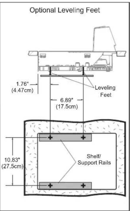
Figure 14. Medium Shelf Models 8302/8304/8402/8404 Reference Dimensions

Figure 15. Medium Flanged Models 8302/8304/8402/8404 Cutout Dimensions

Figure 16. Medium Flanged Models 8302/8304/8402/8404 Ref. Dimensions

Figure 17. Long Shelf Models 8303/8305/8403/8405 Cutout Dimensions


Figure 18. Long Shelf Models 8303/8305/8403/8405 Reference Dimensions

Figure 19. Long Flanged Models 8303/8305/8403/8405 Cutout Dimensions

Figure 20. Long Flanged Models 8303/8305/8403/8405 Reference Dimensions

Checkstand Mounting
There are a number of things to take into account when installing the unit into a checkstand. Key factors are ergonomic/worker safety, loading capacity and stability. Consider the scanner or scanner/scale's weight when calculating the robustness of construction needed to support it as well as maximum capacity of weighed and scanned items.

NOTE
If you choose to rout a countertop with a thickness of 0.75" (1.9 cm) plywood, you'll need to add a backing strip that supports the area routed out for the support flanges (see Figure 9). This support strip should minimally be made of 0.75" (1.9 cm) thick plywood and be approximately 4.0" (10.2 cm) wide and 14.0" (35.6 cm) long. This strip should be glued as well as screwed to the underside of the countertop.
Checkstand Vibration
Proper function of the scanner/scale is dependent upon an installation which minimizes excess vibration from conveyor belts, fans, and other such equipment. See Chapter, if vibration is suspected of causing operational problems.
Installation Overview
The preceding Site Preparation Overview on page 16 dealt with installed location and counter preparations to accommodate the scanner or scanner/scale. Having completed those steps, physical installation of the scanner or scanner/scale can begin. The following instructions apply to all models.
This chapter describes:
- Unpacking the unit.
- Verifying operation before connecting to a POS system.
- Routing and connecting cables.
- Validating that your scanner communication parameters match the POS terminal's system requirements.
- Confirming connection to the (optional) EAS system.
- Functional testing to verify operation when connected to the POS system.
The following text describes each of these steps.
Unpacking
To unpack the unit:
- Inspect the package for signs of damage that may have occurred during shipping. If damage is found, report it to your carrier immediately.
- Lift out the accessory box containing the AC/DC Power Supply, optional Remote Scale Display and cable (if present), and the Quick Reference Guide.
- Remove the Quick Reference Guide and familiarize yourself with the unit's controls and features. Leave the guide at the checkstand when the installation is complete.
- Remove the protective packing and carefully lift the unit from the carton. Be sure to save the box and all packing material. In the event of failure, the unit must be returned to the factory in its original packaging.
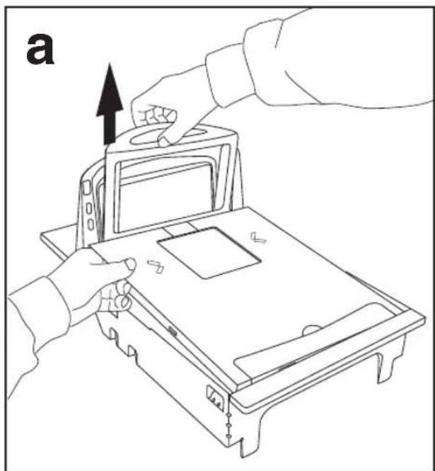
- Carefully lift off the L–Platter as shown in Figure 29 and remove the protective foam pieces securing the weigh mechanism. Set the platter back in place.

NOTE
For added protection during shipment, the L-Platter is covered with a tight-fitting layer of vinyl as shown in Figure 21. This vinyl layer MUST BE REMOVED before placing the unit into service.
Figure 21. Remove Protective Vinyl

- Proceed to Operational Verification below.
Operational Verification
Follow these steps to ensure that your unit has arrived undamaged and is fully functional before installing it in the counter and connecting it to your POS system.
-
EAS units ONLY: It could be necessary that EAS connections be made previous to power-up. Reference the EAS system manufacturer's instructions for more details.
-
Scanner/Scale units ONLY: If the unit is a scanner/scale, connect the Remote Scale Display to the proper connector on the unit's connector panel (refer to Figure 25). Note that if the Remote Scale Display is not connected, a scanner power-up Selftest will sound a long, low beep, and the number "8" will appear on the 7-segment display indicating a remote display error. Power-down, connect a known-good Remote Display to the appropriate port, and restart to correct this problem. Alternatively, you can disable the Remote Display using programming bar codes (see Chapter 6, Programming, for more information).
-
Connect the power cable at the scanner, then at the AC outlet. When power is applied to the unit, the normal indicator sequence is:

NOTE
- The scanner indicator (top-most, green LED) will be lit (dim) steadily.
- The 7-segment display will flash the number '8'. indicating initialization.
- If the Selftest detects a problem, the 7-segment display will display a number code. Refer to Chapter 4, Problem Isolation, for a description of failure codes and problem isolation procedures.
Scale calibration may be necessary to obtain a zero reading on the display on rare occasions.
- The unit should be permitted to reach thermal equilibrium before proceeding to the next steps. (Reference the topic Warm-Up Time on page 8.) When the unit is moved from a cooler temperature (such as a storage area) to a warmer environment (such as a checkstand location), a period of 60 minutes must be allowed to acclimate the unit to ambient conditions. Once installed and powered up, a “power-up” warm-up period of 15 minutes must be allowed before calibrating or performing weighing operations. These two warm-up periods may run concurrently.
- Verify that the scanner or scanner/scale passes an operational test by observing the following:
Scanner — Pass UPC/EAN bar code labels in front of the scanner's windows. Since the interface cable is not yet connected to the POS terminal, the scanner may be limited to reading only one or two labels (see the note that follows). The scanner indicates when each label has been successfully read by flashing the green scanner light and emitting a good read tone (beep). Some host interface types may “chirp” instead of beeping.

NOTE
When not connected to the host, the scanner may be limited to reading only one or two labels. (This limitation is dependent upon the interface type.) To scan multiple labels without connecting to the host, place the unit in Scanner Diagnostic Mode by pressing the Volume/Tone Push Button for four seconds.
EAS System — The way in which EAS labels are deactivated is dependent upon which aftermarket EAS system was purchased and installed. See the user's manuals and other documentation accompanying that EAS equipment.
Scale — If the Yellow (bottom) LED/Button is not lit, press that button momentarily. If the scale is operating correctly, the yellow LED will illuminate and remain on steady, and the display will show a reading of 0.00 lb (0.000 kg for metric). If the display is blank or a -0- is displayed, it may be necessary to calibrate the scale before continuing. Refer to Chapter 5, Calibration, for calibration procedures.
Remote Scale Display — Check to verify that 0.00 lb (0.000 kg for metric) is displayed, then place an item on the weighing platter. Verify that the display shows a weight and that the yellow LED goes out. Remove the item and observe that Remote Scale Display shows 0.00 lb (0.000 kg for metric) and that the yellow LED is On.
- Unplug the AC power cord from the outlet and disconnect the power cord and Remote Scale Display cable from the scanner's connector panel.
After you have verified that the scanner, EAS system and scale (if present) are completely functional, continue with the following procedures to complete the installation.
Diagnostic Modes
Two diagnostic modes are available which allow you to initiate scanner or scale diagnostic tests, as well as verify the scanner's ability to read bar codes.
Scanner Diagnostic Mode
While in Scanner Diagnostic Mode, continuous scanning of labels is allowed, permitting the user to scan an unlimited number of bar codes while troubleshooting problems. Under normal operation, the scanner stores label data, awaiting the signal which transmits it to the host. When the scanner is not connected to a host, it may read and store only up to two labels, then quit reading until power is cycled (clearing the memory). This mode of operation removes this limitation.
To place the scanner in Scanner Diagnostic Mode, press the Volume/Tone (top) Push Button for approximately four seconds. While pressing the button, the scanner will first sound three tones, wait a
few seconds, then sound six rapid tones; after which you should immediately release the button.
While in Scanner Diagnostic Mode, identification numbers for interface ^1 type, firmware and configuration will scroll continually across the scanner's 7-segment FRU (Field Replaceable Unit) display. This is useful information for field diagnostics. See Figure 40 for the location of the display. For example, if the dual cable RS-232 interface (type 05) were enabled, the firmware designation was R96-1234, and the configuration was R96-5593, the following would be shown (slowly, with blanking between each of the items):
IF-05 r96-1234 r96-5593.
To exit Scanner Diagnostic Mode, cycle power to the unit or press and hold the Volume/Tone Push Button for eight seconds to reset the scanner. See Chapter 3, Scanner and Scale Reset for more information about unit resets.
Scale Diagnostic Mode
To enter Scale Diagnostic Mode, press the Scale Zero Push Button for approximately four seconds. Six rapid tones will be sounded, indicating the unit is leaving normal operation and entering Scale Diagnostic Mode. The Remote Display will flash a '1' across the display while the diagnostic routine is being run. When diagnostics are completed successfully, the display will indicate that the unit has passed the diagnostic test by displaying . Next, the display shows a listing of how many times the unit has been calibrated and zeroed in the form of: where x equals the number of times the scale has been calibrated. Next, the unit will display Zero XXX where x is the number of times the scale has been zeroed. Finally, all segments will be displayed in the form of: -18.850/ visual verification of display function.
If the diagnostics routine is not completed successfully, the scanner will sound a series of tones and the Remote Display will show an error code. Turn to Chapter 4, Problem Isolation, for a description of error codes.
Press the Scale Zero Push Button once more to reset the unit and exit Scale Diagnostic Mode. See Chapter 3, Scanner and Scale Reset for more information about unit resets.
Cables & Connections
Considerations when routing the power and interface cables for the scanner and scanner/scale are:
- Ensure that cables are not pinched, kinked or pierced. - Do not route interface cables in close proximity to electrical motors or other sources of electromagnetic interference.
Do not plug the AC power cord into the outlet at this time. It is a good practice to always connect the power cable to the scanner first before plugging it into the AC receptacle. The procedures titled, Set-Up, provided later in this chapter will instruct you to connect the power cord at that time. Figure 22 illustrates the basic cable routing scheme.
Figure 22. Cable Routing

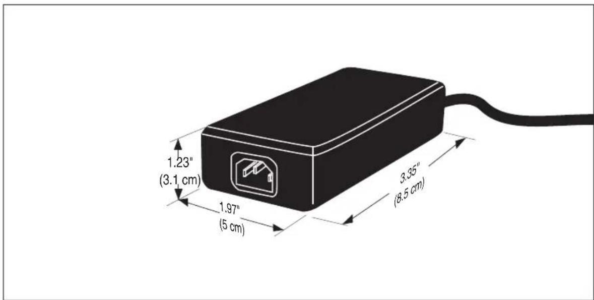
Figure 23 provides physical dimensions for the AC/DC Adapter (part number 8-0582).
Figure 23. Physical Measurements: AC/DC Adapter
Remote Scale Display Placement/Installation
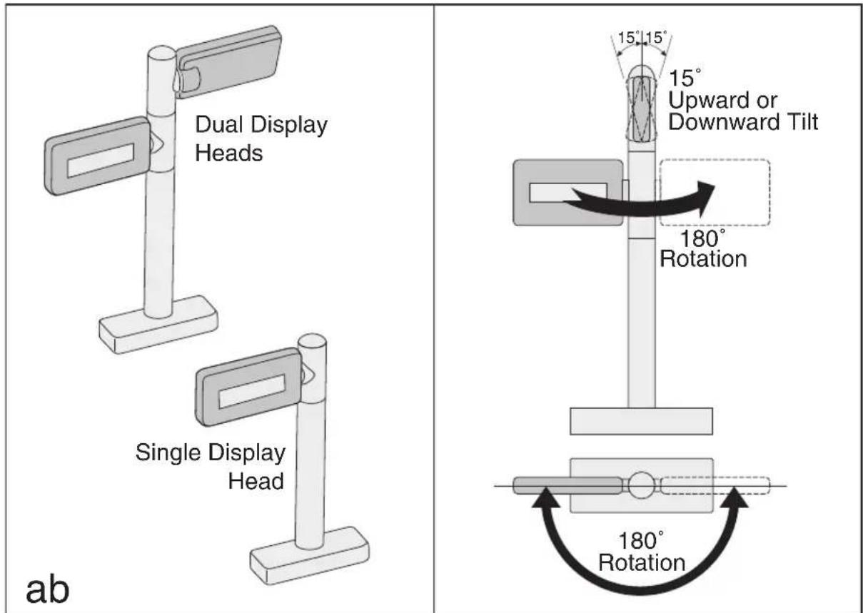
The modular Remote Display is designed so that single display heads can be stacked to form a dual display as shown in Figure 24a in order to address the specific viewing needs of both the customer and the cashier.
Factors to consider when installing this device are:
• Lighting Considerations on page 37
• Viewing Angle on page 38
• Remote Display Cabling on page 39
Lighting Considerations
The display(s) will be easily readable unless placed in direct sunlight or other very strong light sources. Light interference will not be a factor in most installations. For best viewing, the display head(s) can each be rotated up to 180^ around the post and/or tilted 15^ backward or forward.
Viewing Angle
The optimum display angle is directly facing the viewer. Tilt and rotatioin adjustments can be made as shown in Figure 24b. To ensure that displays are easily readable for customers/cashiers of average height, display heads should be between 48" to 60" (122 to 152 cm) from the floor.

Check with local Weights and Measures authorities regarding proper positioning of scale displays used in retail trade.
Figure 24. Modular/Adjustable Remote Scale Display
Remote Display Cabling
Your installation should also take into account the routing of Remote Display cabling. Ensure that distance and obstacles spanned by the routed cable will not kink, pinch or stretch it. Also keep in mind you may need to drill a hole through which to route it.

NOTE
The Remote Scale Display connector end may be secured with a rubber band during shipping to prevent damage to the "locking tabs" (see Figure 26). After routing the cable, remove this rubber band before connecting. Failure to remove the band will keep the connector from latching properly.
Placing and Installing the Remote Scale Display
Reference Figure 26 while performing these procedures.
- Determine where you want to install the Remote Scale Display based on your counter design, the viewing angle, lighting considerations and cable routing discussed previously. Reference Figure 24 for the display's physical dimensions. Optimally, the display(s) should be approximately eye level to the viewer(s).
- Use the template provided in Figure 27 to mark locations of the mounting screw and cable routing holes. The mounting screw holes are on 3–1/2" (85.1 mm) centers. The cable can either be routed through a ^3/4 " (19 mm) diameter hole directly under the mounting base or through the cutout in the back of the base (see Figure 26).
- Drill the mounting screw holes using a drill bit of the appropriate diameter for your mounting screws or bolts.
- Drill the cable routing hole using a ^3/4" (19 mm) drill bit (optional).
Figure 25. Physical Measurements: Remote Display

- Feed the entire length of the Remote Scale Display interface cable through the cable routing hole so that the assembled Remote Scale Display can be positioned over the mounting screw holes.
- If present, remove the rubber band from the connector end.
- Install mounting screws or bolts to complete the installation of the Remote Scale Display. Take care not to pinch or pierce the interface cable while securing the Remote Scale Display to the checkstand.
Figure 26. Remote Scale Display Mounting

Figure 27. Remote Scale Display Mounting Template

Changing Weighing Modes
Your scanner/scale has been programmed for weighing in either pounds or kilograms depending upon the initial operating environment that was specified when you ordered your scanner/scale. If you need to change from pounds to kilograms or vice-versa, call technical support.
You can verify that the scale is set correctly for your country's requirements by observing that the Remote Scale Display shows the appropriate measurement symbol (lb or kg) when the power-up Selftest is completed.

NOTE
Any time the scale weighing mode is changed, the scale must be re-calibrated before commercial use.
Set-Up & Installation
These setup and installation procedures assume that you have already prepared your checkstand to receive the scanner or scanner/scale. If you have not already made the counter cutout and routed power and interface cables, do so now as described in the previous instructions. If your checkstand has been prepared, proceed as follows:
Set-up
- Place the scanner on the checkstand next to the counter cut-out.
- Make all connections to peripheral devices, such as the Remote Scale Display (see Figure 26) and, if your installation includes an EAS system, refer to that manufacturer's instructions for connection and start-up procedures.
- Route the cables up through the cutout and connect the scanner and scale interface cable(s), EAS cable and Remote Scale Display cable (optional) to the scanner. Some POS terminals require two interface cables; one for the scanner interface and one for the scale interface. Refer to Figure 28 for cable connection locations.
If you have a scanner with no scale, there will be only one interface cable to the POS terminal.
- Connect the power cord to the scanner and route the other end down through the checkstand to the AC power outlet. DO NOT plug the power cord in at this time.
Figure 28. Connecting Cables to the Scanner/Scale
Installation
-
Make sure that all cables are firmly attached (except that the AC/DC power supply should not be connected to the AC outlet yet). Reference Figure 9 and Figure 28.
-
Remove the platter to gain access to the interior lift handle. Grasp the platter in the positions shown in Figure 29 and gently lift it from the scanner. If the top edge of the platter is blocked, you may find it easier to grasp the platter vertical bezel as shown in Figure 29b.

Figure 29 illustrates an L-shaped weigh platter, which features a vertical bezel. Your platter may not contain a vertical bezel.
Figure 29. Removing the Platter
natural_image
Line drawing of hands operating a device with an upward arrow indicator (no text or symbols present)
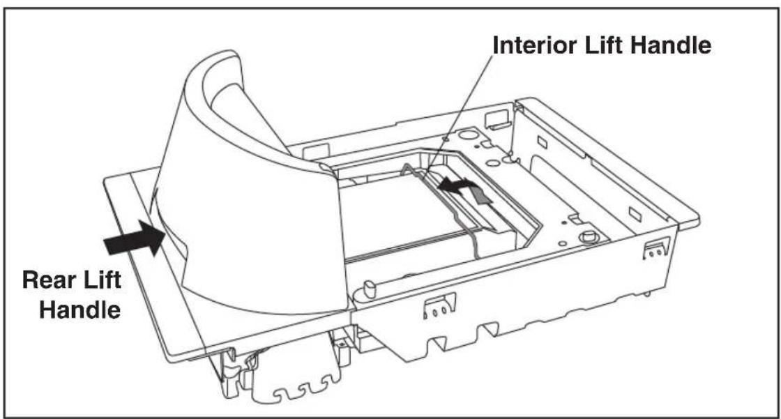
- Rotate the Interior Lift Handle up as shown in Figure 32 and hook the fingers of both hands in the lift handles indicated.
DO NOT attempt to lift the unit using the plastic edges, scale frame, or any features other than the lift handles.
Figure 30. Using the Lift Handles
-
Lower the unit into the counter opening, ensuring that none of the cables are pinched, pierced or crimped.
-
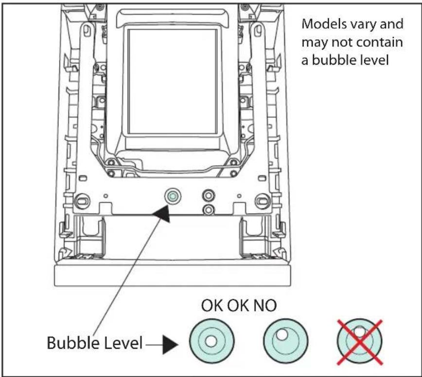
View the bubble level (if present ^1 ) located on the scanner's spider assembly to ensure the scanner is level. As shown in Figure 31, the air bubble should appear fully within the circle indicated. The air bubble can touch the circle, but must not overlap it. Apply shims beneath the scanner bottom or adjust the shelf to allow level installation.
Figure 31. Using the Bubble Level
- Re-install the Platter and verify that it is flush or just below flush with the countertop. This is necessary to provide smooth scanning from either direction. Make adjustments as needed to align the platter with the counter by moving support rails up or down, or consider installing screws in positions that will allow their use in adjusting the unit's position. Ensure that leveling is maintained if adjustments are made.

Failure to install a scanner/scale in a stable and level position will inhibit weighing, calibration and zeroing operations. The platter MUST make unobstructed contact with all of its supports for proper weighing operation.
- Once installation is complete, proceed with the Operational Verification on page 32 procedures that follow.
Figure 32. Adaptive Scale Platter Option
Some Platters have been shipped with installed spacers on their undersides at all four corners. These specially-configured Platters are provided for customers wishing to add an adaptive scale to their unit at a later date. Until such time as the adaptive scale is installed, the four spacers should be left in place to ensure that the Platter rests evenly at its correct height when positioned on the scanner.
To remove the spacers, loosen and remove the single screw for each as shown in Figure 33.
Figure 33. Removing the Adaptive Scale Spacers

System Power-Up Recap
The System Power-Up procedure may vary depending upon the requirements of your POS system. It is generally a good practice to power-down (switch off) all equipment prior to connecting cables. Check with your System Supervisor and/or refer to your POS terminal manual for proper power-down and power-up procedures and interface requirements when connecting any peripheral device. If you have not identified any specific requirements for your POS system, follow these steps.
- Power-down the POS terminal.
- Ensure that power is disconnected from the scanner.
- Connect the scanner and scale interface cables to your POS terminal. This connection may use one or two cables depending upon your POS terminal interface.
- [EAS units ONLY] Connect the EAS interface cable.

NOTE
SENSORMATIC EAS SYSTEMS:
Always Apply power to the EAS Controller box before powering on the scanner.
-
Connect the Remote Display cable if your model is a scanner/ scale and make any connections to optional equipment, such as a handheld scanner.
-
Power-up the scanner or scanner/scale by connecting the power cord to an AC power outlet. Wait for the unit to complete the Self test routine (10 seconds maximum). Successful scanner power-up is signified by any or all of the following:
-
Facet wheel shows movement
- Lasers turn on
- Status LED(s) turn on
- Speaker sounds tone(s)
- Remote display [if present] shows message
-
A single red dot is visible on the 7-segment display
-
Power-up the POS terminal. Verify that scanning, deactivation and weighing functions are operational and that data is properly communicated between the scanner and your POS system. (Scan, deactivate and weigh a few items.) If problems are encountered, refer to Chapter 4, Problem Isolation.
-
You have now completed installation and system integration of the scanner or scanner/scale. At this point, the scale must be calibrated and certified in accordance with the requirements of your state and/or local requirements. Refer to Chapter 5, Calibration, for calibration procedures.
NOTES
Chapter 3
Operation and Maintenance
The information contained in this chapter describes how to operate and maintain the scanner, and optional scale and EAS systems. Topics include “how to’s” on scanning, EAS label deactivation, weighing, re-zeroing the scale, removing the top cover and cleaning the upper and lower windows.
Scanning Items

NOTE
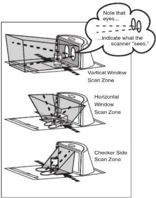
To scan items using the scanner, slide or push them through the scan zone as shown in Figure 34. The scanner will work equally well with either a left-to-right or right-to-left motion through the scan zone. There is rarely a need to reorient an item's bar code since the scanner has a 360 degree view around an item.
"Limited Scanning Mode" is entered by default by interfaces such as USB and IBM until a Point Of Sale (POS) terminal enables scanning. This mode allows the scanner to read labels without a host interface enabled. The scanner will only process programming labels and emit a bad label read indication ("chirp") for all other labels.
Figure 34. Scan Zone
Proper Scanning Technique
The scanner was designed to provide the ultimate in ergonomic enhancements for Point-Of-Sale (POS) scanning. To take advantage of these advancements:
Practice the techniques below to improve scanning efficiency:
- Move the product across the horizontal window (See Figure 34).
- Since the scanner can reads labels 360 degrees around the product, don't favor either the horizontal or vertical scan windows. Keep items in their natural orientation.
- Remember to slide or push items rather than picking them up. By avoiding any gripping, twisting and rotation of your hands and wrists, you can prevent repetitive motion injuries. This technique also relieves you from lifting possibly thousands of pounds per day.
- Develop a smooth fluid motion during scanning, sharing work equally between hands.
- Use the entire hand for grasping and lifting items.
- Develop efficient scanning motions, not necessarily faster hand movements.
- Learn typical locations for bar codes on packages; avoid "flipping" or rotating the items during scanning.
- Learn how the scanner functions and where the scanning area is located.
Deactivating Security Labels
EAS (Electronic Article Surveillance) labels can be detected and deactivated by a system equipped with this option. This is accomplished by means of a deactivation antenna mounted under the scanner platter. EAS labels should be brought near the antenna to be deactivated. Reference the documentation for the EAS device for more details about its installation and function.
Proper Weighing Technique
- The L-shaped All-Weighs™ platter allows you to place items anywhere on its surface, including leaning against its vertical section, to be weighed accurately. The “Produce Rail” or (when raised) the “Produce Bar” also provide a convenient way to ensure items do not rest on the counter or other non-weighing surfaces. (Reference Figure 35.)

NOTE
It is important that items rest entirely on the platter for their full weight to be accurately recorded.
Figure 35. All-Weighs™ Platter & Item Placement

- Once weighed items are in place, enter PLU (price Look-Up) data as described in your POS system instructions. Item weight is displayed on the Remote Display and/or the host display.
- Remove the item from the weigh platter.
Operational Controls
The function of scanner and scale controls and indicators is listed in Appendix A, LED/Beeper Indications & Controls. Turn to that appendix for full details.
Operational Modes
The scanner or scanner/scale features a number of modes that are important to both the user and the system support personnel. These modes can be combined into three groups: pre-operational, operational, and additional functions. The following text describes these modes, what they mean, and how and when they are seen.
Power-Up/Selftest & Pre-Operation
Pre-Operation describes those steps that must be successfully completed before the scanner sounds the initial good read tone and illuminates the lamps indicating the scanner and/or scale are ready for operation. These steps include Power-Up Selftest, Error Reporting, and Operational Configuration.
Power-Up/Selftest
Power-Up Selftest begins when power is applied. The scanner's software immediately begins the testing sequence to verify that all systems are functioning properly. This routine, which only takes a few seconds, checks all the functions of the scanner, EAS deactivation system, scale, remote scale display and interface prior to indicating that it is ready for operation.

NOTE
A tone indicating Selftest is complete is a configurable feature. See the topic Power-up Beep Control on page 127 in the Programming chapter of this manual.
Error Reporting
If a fatal error is detected during Selftest or operation, the unit will not advance to Normal Operation Mode. Selftest diagnostics will cause the unit to sound a long, low tone and/or display an error message on the 7-segment display indicating where the failure occurred. These messages are coded to assist the repair technician in identifying the failed component. If an error is indicated, make note of it and contact your supervisor or technical support representative. A table containing descriptions of these error codes is included in Chapter 4, Problem Isolation.
If a non-fatal ^1 error is detected (such as the loss of one of the two lasers), the unit will sound a long, low tone and display a number on the 7-segment display. The unit will advance to Normal Operating Mode, but performance may be affected until a correction or repair is made.
Operational Configuration
Once Selftest diagnostics have been successfully run, a tone is emitted (if configured to do so, and the unit enters an operational configuration state. The scanner or scanner/scale will automatically load your specific interface settings which are required to communicate with the host system. There are two conditions that must be met before the unit can enter Operating Mode:
- No bar code label can be in the scan volume while the unit is in this state. Progress is halted until the label has been removed, thereby ensuring that no extraneous bar code data is send to the host.
- If your scanner has a scale, the scale cannot be in motion (usually caused by excessive vibration in the checkstand) for this test to succeed. A “Scale in Motion” status will be indicated by displaying a period and the applicable weight unit (lb or kg) that is selected. kg
- The scale must be able to "capture" zero weight. The -0 - display will be seen if there is a weight on the platter at power-up. Removing the weight or pressing the Scale Zero Push Button should allow the scale to find zero.
-
When the scanner or scanner/scale completes its Selftest successfully, it emits a tone (when configured to do so) and enters Operating Mode.
-
Scanner behavior under non-fatal error conditions is configurable.
See Chapter 6, Programming for more details.
Operating Mode
Operating Mode includes Normal Operation (scanning, EAS deactivation and weighing) and Sleep Mode. These two modes are most commonly observed by the user/operator.
Normal Operation
This condition is indicated by the scanner green LED being on dim and steady. For scanner/scale models, the scale yellow LED indicates that the scale senses a weight of zero on the platter. If you have a scanner without scale model, the yellow lamp will not be lit when the scanner is ready for scanning.

Yellow and Green LED indications are configurable. Your scanner may not be programmed to operate in the standard manner described above.
Once the scanner enters Normal Operation, it begins a countdown sequence. If there is no activity during a preset period of time (also called time-out ^1 ), the unit will shut off the laser and/or motor in order to prolong the life of the electrical and mechanical components. Once the scanner has timed out, it enters Sleep Mode.
Sleep Mode
After the scanner has been left idle for a preset period of time, the laser and/or motor automatically turns off (goes to sleep). This state is called Sleep Mode, and is indicated by a “slow” blink of the green light (blinking at a 2-second rate). To wake up the unit, press anywhere on the weigh platter (scanner/scale models only), press the Volume Selection switch or wave your hand over the horizontal window. The unit will recognize any of these signals as a wake-up call and instantly return to Normal Operation.
Additional Functions
Additional scanner and scale functions include programming, running scanner or scale diagnostics, initiating a reset, zeroing the scale, and calibrating the scale.
Programming
When your scanner or scanner/scale is shipped from the factory it is configured to work with the POS system interface at your store and read the bar code symbologies you designated. If you need to change this configuration information for any reason, Chapter 6, Programming, contains special bar code labels for changing the unit's settings.
Diagnostic Mode
Refer to Chapter 2, Diagnostic Modes, for details about running scanner and scale diagnostics. Turn to Chapter 4, Problem Isolation, for a description of error codes resulting from diagnostics.
Scanner and Scale Reset
The reset procedures and indicators are identical for scanner and scanner/scale models. As with any electronic equipment, it is sometimes necessary to reset the electronics. The reset procedure allows you to initiate a reset command to the scanner. This may be necessary if the POS terminal has been switched off or the store system has been reset while the unit is on. Reset can also be used to initiate and run the unit's internal Selftest routine.
Pressing and holding the Volume/Tone Push Button for approximately eight seconds initiates a reset, which is sounded by a rapid number of beeps. If the motor had been spinning, the lamps will blink while the motor spins down. At that point, the motor will spin back up and the scanner will continue to run the Selftest diagnostics. For more information, see the topic, Power-Up/Selftest & Pre-Operation on page 54, earlier in this chapter.
Scale Adjustments
The scale allows two user adjustments: zeroing and calibration. The first, and most frequently performed, is ‘zeroing’ the scale. This operation resets the scale’s “at rest” reading to zero which must be within the range of -0.2 pounds (-0.09kg) to +0.6 pounds (0.27kg) since the last calibration. While the ‘at rest’ reading remains within the zero range, the scale will automatically adjust itself to true zero. The scale also automatically zeros itself on power-up if the weight present on the scale is within these defined limits.
Zeroing the Scale
The zeroing operation may be performed by checkers and other store personnel. Pressing and releasing the Scale Zero Push Button should return the scale to Normal Operation. If the zero point moves out of the zero range due to debris accumulation or other causes, pressing the Scale Zero Push Button will not reset the zero point. In this case the weigh platter must be cleaned, debris chutes cleared of debris or the scale must be recalibrated.
With the scanner/scale powered-up and at operating temperature:
- Remove everything from the weighing surface of the scanner/scale.
- Press the Scale Zero Push Button. (See Figure 1).
- The Zero ^1 light will turn on and the display will show 0.00 lb (0.000 kg). If it does not, see Chapter 4, Problem Isolation.
- You have completed the scale zeroing function.
Calibrating the Scale
The second adjustment, calibration, defines and sets a standard reference weight range against which all product weights are compared. If your scale is set for weighing in pounds, this range is 0 – 30 pounds, and, if your scale is set for weighing in kilograms, the range is 0 – 15 kilograms. The scale must be calibrated upon initial installation, whenever the scale cannot be zeroed, when the scale diagnostics indicate a calibration error, when the weighing measure (pounds or kilograms) is changed, or when the scale module has been replaced.
Normally, once the scale has been calibrated, the calibration must be verified and/or approved by a local regulatory body. In many areas of the United States, the scale calibration switch must be sealed before being placed into service. Consult the agency responsible for regulating weighing devices in your area to ensure that you are meeting all legal and regulatory requirements. Chapter 5, Calibration, describes the calibration sequence and verification process.
Calibration can only be performed if the tamper seal that secures access to the Calibration Switch is broken and the switch cover is removed. Breaking the seal may legally render the scale inoperable until it has been recertified and a new seal attached. Consult your local regulations before removing the calibration seal if you are unsure of the legal requirements. Although the scale will physically continue to weigh products, a broken seal may require recertification by a proper authority as designated by your local laws.
Operational Maintenance
The scanner or scanner/scale will provide dependable service for many years. The following maintenance procedures will keep your scanner or scanner/scale operating at peak performance.
Cleaning the Platter and Scan Windows. Clean the exterior surfaces of the horizontal and vertical scan windows at least twice daily with a nonabrasive, mild, water-based glass cleaner and paper towels or lint-free cleaning tissues. The textured plastic surfaces and stainless steel can also be cleaned using the same cleaning agents.
Cleaning the Air Gap/Debris Chutes & Drip Rail. Daily, clear the debris chutes between the platter and the outer housing. Most items can be cleared from the debris chutes by carefully running a thin stiff object like a credit card along all sides of the weighing surface. If necessary, remove the top cover to clear the debris chutes and drip rail.
Vertical Scan Window Replacement
The Vertical Scan Window is a replaceable part. Follow the instructions below to remove and replace a standard or L-Platter Vertical Scan Window.
Standard Vertical Scan Window Removal
- Lift up on the vertical bezel as shown in Figure 36a and tilt its top up and away from the scanner as shown.
Figure 36. Removing/Reinstalling the Vertical Bezel
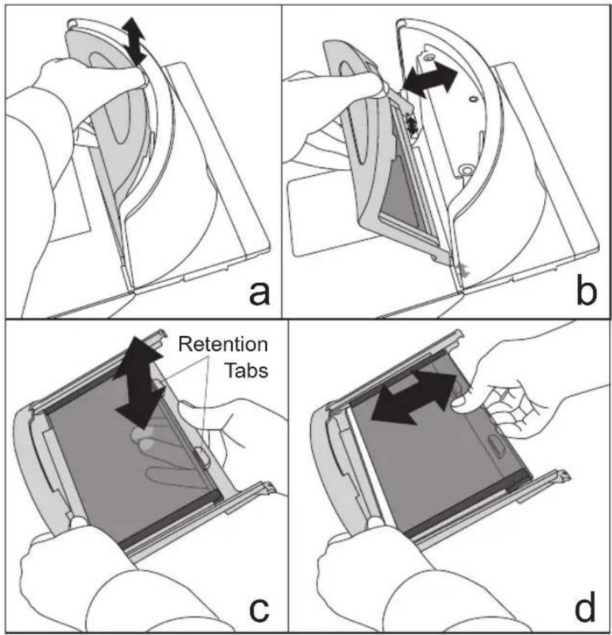
-
Press from the opposite side to release the edge of the Vertical Scan Window from the two retention tabs shown in Figure 36c.
-
Slide the window from the bezel as shown in Figure 36d. Carefully dispose of any damaged glass.
-
Fully seat the new Vertical Scan Window into the window channel, engaging it within the retention tabs. Reference Figure 36d and Figure 36c.
-
Clean both sides of the new Vertical Scan Window using a paper towel or lint free cleaning tissues dampened with a mild, water-based glass cleaner. DO NOT use abrasive cleaners or pads.
-
Tilt in the bezel to seat the two ears at the bottom corners of the bezel into their holes in the scanner and push in on the top of the bezel to securely snap it in place (see Figure 36b). Vertical Scan Window replacement is now complete.
L-Platter Vertical Scan Window Removal
- Grasp the platter as shown in Figure 37 and gently lift it from the scanner.
Figure 37. L-Platter Removal/Reinstallation

natural_image
Line drawing of hands operating a device with an arrow indicating upward motion (no text or symbols present)
- If the top edge of the platter is blocked, you may find it easier to use a coin to lift up an edge of the platter as shown in Figure 37b, then grasp the platter vertical bezel or other exposed edge.

NOTE
Use caution to avoid damage to the now exposed horizontal and Vertical Scan Windows. If cleaning of these windows is necessary, use a nonabrasive, mild, water-based glass cleaner and paper towels or lint-free cleaning tissues and take care to avoid scratching these windows (damage to the windows can degrade scanning performance).
- The Vertical Scan Window is held in place by two tabs each on its top and bottom edges. To remove it, carefully push out on the top as shown in Figure 38 and lift it out. Carefully dispose of any damaged glass.
Figure 38. Vertical Scan Window Removal/Replacement
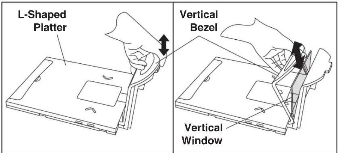
-
Fully seat the new Vertical Scan Window into the window channel within its bottom retention tabs. Tilt the window in to engage the two tabs at the top of the retainer and carefully snap the window to secure it in place.
-
Clean both sides of the new Vertical Scan Window using a paper towel or lint free cleaning tissues dampened with a mild, water-based glass cleaner. DO NOT use abrasive cleaners or pads.
-
Re-install the platter. Vertical Scan Window replacement is now complete.
Horizontal Scan Window Replacement (WRG)
Wear Resistant Glass (WRG) horizontal scan windows are replaceable and can be removed and replaced following the instructions below.

NOTE
Sapphire glass does not require replacement, so it is permanently fastened in place. Do not attempt to remove Sapphire glass from the platter.
- Remove the Platter from the scanner as shown in Figure 37.
- Turn the platter upside down on a clean, dry surface and remove the two screws shown in Figure 39a. Retain the screws for later re-installation.
- Tilt the Window Retainer up and away from the platter as shown.
- Lift out the Window Gasket and WRG Window from the Platter as shown in Figure 39b and carefully dispose of any damaged glass.
- Position the new WRG Window and its gasket as shown in Figure 39b.
- Guide the Window Retainer to seat its edge under the tabs and match the screw holes as shown in Figure 39a.
- Secure the retainer in position using the original two screws.
- Clean both sides of the new WRG window using a paper towel or lint free cleaning tissues dampened with a mild, water-based glass cleaner. DO NOT use abrasive cleaners or pads.
- Re-install the platter. WRG Window replacement is now complete.
Figure 39. Removing/Replacing the WRG Window

NOTES

Chapter 4
Problem Isolation
In the event of a suspected functional problem, use the trouble-shooting references provided in this chapter. This useful information will help you to identify and resolve the cause of the problem.
The scanner/scale has a number of features that indicate when a scanner or scale problem occurs. The unit may:
- emit a series of tones
- light the 7-segment (FRU status) display
- flash one or more LEDs
- display error codes on the Remote Display (if installed)
Three error reporting modes are used: Power-Up Selftest, Operational tests and Diagnostic tests. These test sequences are explained on the following pages.
Power-Up Selftest
The Power-up Selftest is a pre-operational series of tests that must be successfully completed before the scanner indicates readiness for operation. This pre-operational period is the time between power-up and normal operation during which the motor comes up-to-speed and software, firmware and hardware are being tested. These tests ensure that all subsystems are fully functional before turning on the Visible Laser Diode (VLD). Refer to Chapter 3, Operational Modes for a more detailed description of this and other scanner and scale modes.
Operational Tests
These are the tests that run continually during Normal Operation and Sleep Mode. Firmware checks all subsystems, accessory connections and the POS interface to verify everything is operating normally. If a problem is detected at any time, a long, low tone is
sounded, an error code is shown on the 7-segment display, and operation may be halted. If you press the Volume/Tone Push Button at that time, a series of tones will be sounded that matches the error code displayed.
Diagnostic Tests
See Chapter 2, Diagnostic Modes, for details about running diagnostic tests for the scanner and/or scale. If a problem is discovered during diagnostics, the scanner will provide feedback about the source of the problem. The remainder of this chapter describes these failure indications and includes troubleshooting flowcharts to help isolate the problem.
Diagnostic Procedures
Your Point-Of-Sale (POS) system may contain many components that operate as a system. Since almost all scanner or scale problems are caused by either the scanner, scale, POS terminal or communication links between them, these troubleshooting flowcharts focus on these components. Additionally, the optional Remote Scale Display, AC/DC Power Supply and their cables are potential problems addressed in this chapter.
The flowcharts provided in this chapter walk you through a diagnostic process that will isolate the failed component and instruct as to the corrective action required. Since internal scanner and scale components cannot be replaced by an operator or installer, most functional errors will require the assistance of a trained technical support person. However, if the problem is caused by faulty cable, power supply or remote display, you can fix the problem by replacing the defective component and complete the installation.
Error Codes
If an error is detected, the scanner will sound a long low tone (for one second) and alternately flash its LEDs, indicating a failure. Following the long low tone, an error code will appear on the 7-segment display (refer to Figure 40). Pressing the Volume/Tone Push button will cause the scanner to sound a series of beeps corresponding to that error code. Table 2 on the following page describes what these codes mean and what action should be taken for each.

NOTE
When troubleshooting, always remember to check all cable connections first before proceeding with other problem isolation steps.
Table 2. Error Codes
| Error Code | Probable Cause Corrective Action | |
| 0 Blinking | Configuration | No POS interface has been selected (Null interface). See Chapter 6, Interface Type to select the required interface using programming bar codes. |
| 1 | Configuration Error | See Chapter 6, Programming, for details about configuring the scanner using programming bar codes. |
| 2 | Interface Board Unplug | unit and call technical support personnel. |
| 3 | Motor Unplug unit and | call technical support personnel. |
| 4 | Horizontal Laser^a | Call technical support personnel. |
| 5 | Vertical Laser^a | Call technical support personnel. |
| 6 | Digital Board Unplug unit and call technical support personnel. | |
| 7 | Scale | See the topic Scale Error Reporting on page 72 in this chapter for problem identification and corrective actions. |
| 8 | Remote Display | Connect the Remote Display. If necessary, replace display or cable. Alternatively, you can disable the Remote Display using the programming procedures described in Chapter 6. |
| A | Control Button Stuck | Check to see if either of the buttons is stuck; free it if possible. If neither button is stuck, call technical support personnel. |
| B | Hardware ID Call technical support personnel. | |
| C | Scale Calibration Calibrate scale or call technical support personnel. | |
| E | CPLD ID Call technical support personnel. | |
| Decimal Point | 3.3 V Present If not lit, call technical support personnel | |
a. If only one laser is non-functional, the scanner may continue to work (this is a configurable feature); however, the 7-segment display will show the error code indicating the failed laser. If both lasers have failed, the 7-segment display will display either a 4 or a 5, and the scanner will cease to function until serviced. No alternate blinking of lamps will occur if only one laser has failed.
Figure 40. 7-Segment LED Display
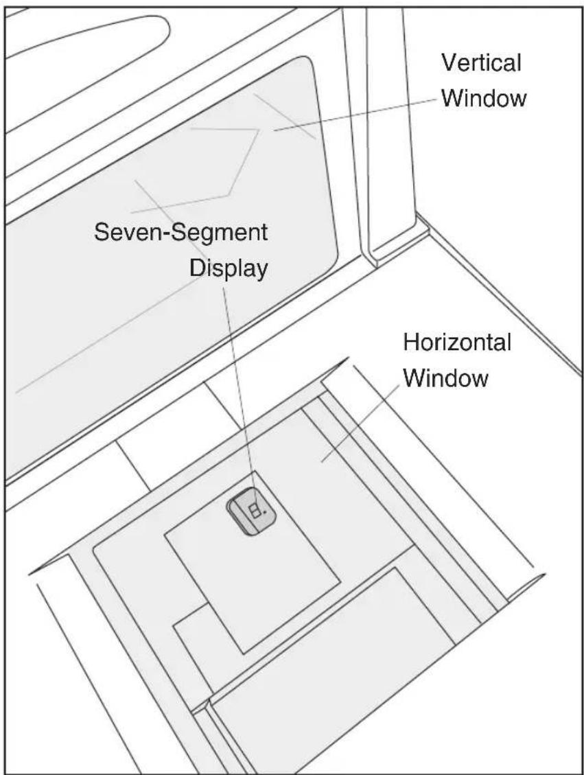
Scale Error Reporting
Scale diagnostics uses the Remote Scale Display and the Zero Status lamp to communicate specific scale failures. The following chart shows the Remote Display messages, the Scale Status lamp indication, the problem that the scale is experiencing and what action should be taken. When troubleshooting, always remember to check all cable connections first before proceeding with other problem isolation steps.
| Remote Display | Scale Status Lamp | Problem Description | Action Required |
| E_1 | Flash, pause, 1 blink, long pause, repeat sequence. | Too much motion at power-up. | Check for stable installation. Scale may require calibration. |
| E__2 | Flash, pause, 2 blinks, long pause, repeat sequence. | Calibration lost. | Call technical support personnel. Re-calibrate; restart; recertify (if required). |
| E__3 | Flash, pause, 3 blinks, long pause, repeat sequence. | Scale communication lost. Internal scanner/ scale problem. | Call technical support personnel; report error. |
| E__4 | Flash, pause, 4 blinks, long pause, repeat sequence. | Scale module failure. | Call technical support personnel; report error. |
| E__5 | Flash, pause, 5 blinks, long pause, repeat sequence. | Internal software fault. | Call technical support personnel; report error. |
| Other Scale Reporting | |||
| -0- | Off | Cannot zero at power-up or weight remains on scale for more than 2 minutes or weight has not returned to zero between POS weight requestsa. | - Check debris chutes.- Verify that the weigh platter moves freely.- Remove item(s) from scale- Press Scale Zero Push Button- for more information.- If the scale still fails to zero, recalibrate the scale. |
a. This is a configurable feature.
Flowcharts
The problem isolation flowcharts on the following pages allow you to identify and troubleshoot problems with your system.
Figure 41. Problem Isolation: Start

flowchart
graph TD
    A["START"] --> B{Does the scanner power-up?}
    B -->|NO| C{Have you checked the power connections?}
    B -->|YES| D{Is the Green LED Lit?}
    C -->|YES| E["Check these potential problems: AC power cord - AC/DC adaptor - AC outlet"]
    C -->|NO| F{Is the Green LED Lit?}
    D -->|YES| G{Does the scanner pass Selftest?}
    D -->|NO| H["Ensure the Green LED is enabled via programming bar codes."]
    E --> I["Call Tech Support"]
    F --> I
    G --> I
    H --> I
    I --> J{Will the scanner read bar codes reliably?}
    J -->|NO| K["Go to Poor/No Reading flowchart"]
    J -->|YES| L{Does the EAS¹ Antenna deactivate tags?}
    L -->|NO| M["Go to EAS System flowchart"]
    L -->|YES| N{Does the scale¹ weigh correctly?}
    N -->|NO| O["Go to Scale flowchart"]
    N -->|YES| P["Call Tech Support"]
    O --> P
    P --> Q["Other Problems? Call Tech Support"]
Figure 42. Problem Isolation: Selftest

flowchart
graph TD
    A["SELFTEST START"] --> B{Does the 7-segment display show 0?}
    B -->|NO| C{Does the 7-segment display show 1. ?}
    C -->|YES| D["Scan the Factory Defaults bar code in Section 6 to enable the default configuration file. Restart the unit."]
    C -->|NO| E{Does the 7-segment display show 2. or 3. ?}
    E -->|YES| F["Call Tech Support"]
    E -->|NO| G{Does the 7-segment display show 4. or 5. ?}
    G -->|YES| H["Error code 4. indicates a failed horizontal VLDM (laser) assembly, while 5. indicates a failed vertical VLDM. If configured to do so¹, the scanner will remain operational with only one of these lasers until the unit can be serviced. If both lasers have failed, the unit will no longer function."]
    G -->|NO| I{Does the 7-segment display show 7. ?}
    I -->|YES| J["Call Tech Support"]
    I -->|NO| K{Does the 7-segment display show 8. ?}
    K -->|YES| L["Go to Remote Display flowchart"]
    K -->|NO| M{Does the Remote Display show -0- or an error (E_ #)?}
    M -->|YES| N["Go to Scale flowchart"]
    M -->|NO| O["Unit passes Selftest"]
    O --> P["Refer to the feature Laser Failure Mode in Section 6."]
    P --> Q["No interface selected (Null Interface). Select an interface."]
Figure 43. Problem Isolation: Poor/No Reading

flowchart
graph TD
    A["Have you verified that all scan windows are clean and scratch-free?"] --> B["POOR/NO READING START"]
    B --> C["Enter Scanner Diagnostic Mode by holding the Volume/Tone Push Button for 4 seconds (until first 3, and then 6 rapid tones are sounded) then release. Scan a known-good bar code."]
    C --> D{Does the scanner read the bar code satisfactorily?}
    D -->|NO| E["Call Tech Support"]
    D -->|YES| F["Reset the scanner by holding down the Volume/Tone Push Button for 8 seconds."]
    F --> G{Does the scanner pass the data to the POS?}
    G -->|NO| H["Go to No Transmit to POS flowchart"]
    G -->|YES| I{Does the scanner read satisfactorily?}
    I -->|NO| J["Verify programmable parameters using the information and programming bar codes provided in Section 6. Check bar code symbology options and other configurable features."]
    I -->|YES| K["DONE"]
    I -->|YES| L{Does the scanner read satisfactorily?}
    L -->|NO| M["Troubleshoot the host or call Tech Support."]
    L -->|YES| N["DONE"]
    N --> L
    style A fill:#f9f,stroke:#333
    style B fill:#f9f,stroke:#333
    style C fill:#ccf,stroke:#333
    style D fill:#cfc,stroke:#333
    style E fill:#fcc,stroke:#333
    style F fill:#fcc,stroke:#333
    style G fill:#fcc,stroke:#333
    style H fill:#fcc,stroke:#333
    style I fill:#fcc,stroke:#333
    style J fill:#fcc,stroke:#333
    style K fill:#fcc,stroke:#333
    style L fill:#fcc,stroke:#333
    style M fill:#fcc,stroke:#333
    style N fill:#fcc,stroke:#333
Figure 44. Problem Isolation: No Transmit to POS

flowchart
graph TD
    A["NO TRANSMIT TO POS START"] --> B["Check the interface (I/F) cable connections. If possible, retest the system using a known-good I/F cable."]
    B --> C{Does the scanner pass the data to the POS ?}
    C -->|YES| D["DONE"]
    C -->|NO| E["Does the scanner read satisfactorily ?"]
    E -->|YES| F["DONE"]
    E -->|NO| G["Troubleshoot the host or call Tech Support."]
Figure 45. Problem Isolation: Scale

flowchart
graph TD
    A["SCALE START"] --> B["View the Remote Display and/or the Yellow scale status LED for the scale error code. Reference the topic, Scale Error Reporting in Section 4 for more information."]
    B --> C{0- shown on RemoteDisplay/ Yellow LED off ?}
    C -->|YES| D{- Check for debris under platter.}
    C -->|NO| E{E_1 shown on Remote Display/ Yellow LED Flash once ?}
    E -->|YES| F["Problem is too much motion at power-up. Correct excess vibration in counter if possible."]
    E -->|NO| G{E_2 shown on Remote Display/ Yellow LED Flash twice ?}
    G -->|YES| H["Problem is calibration lost. Recalibrate the scale using the procedures in Section 5."]
    G -->|NO| I{E_3 shown on RemoteDisplay/ Yellow LED Flash 3 times ?}
    I -->|YES| J["Problem is scale communication lost. Verify cable connections to/from the scale."]
    I -->|NO| K{E_4 shown on Remote Display/ Yellow LED Flash 4 times. Problem is Scale Load Cell failure.}
    J --> L{Is problem fixed ?}
    L -->|YES| M["DONE"]
    L -->|NO| N["Call Tech Support"]
    N --> O["Done"]
    L -->|YES| P["Calibrate scale."]
    P --> Q{Is problem fixed ?}
    Q -->|YES| R["DONE"]
    Q -->|NO| S{Is problem fixed ?}
    S -->|YES| T["DONE"]
    S -->|NO| U{Will the scale calibrate ?}
    U -->|YES| V["DONE"]
    U -->|NO| W["Call Tech Support"]
    W --> X["Done"]
    X --> Y{Is problem fixed ?}
    Y -->|YES| Z["DONE"]
    Y -->|NO| AA["Call Tech Support"]
Figure 46. Problem Isolation: Remote Display

flowchart
graph TD
    A["REMOTE DISPLAY START"] --> B{Is the unit configured for a Remote Display?}
    B -->|NO| C["Use the programming bar codes in Section 6 to enable operation using a Remote Display"]
    B -->|YES| D["Verify that the Remote Display cable is securely attached to the external Remote Display port and reset the scanner."]
    C --> E{Is the problem fixed?}
    E -->|NO| F["DONE"]
    E -->|YES| G["Call Tech Support"]
    F --> H{Is the problem fixed?}
    H -->|NO| I["Re-connect using a known-good Remote Display. Reset the scanner and retest."]
    H -->|YES| J["Replace the Remote Display"]
    I --> K{Is the problem fixed?}
    K -->|NO| L["DONE"]
    K -->|YES| M["Call Tech Support"]
Figure 47. Problem Isolation: EAS System

flowchart
graph TD
    A["NO EAS DEACTIVATION START"] --> B["Check all EAS cable connections."]
    B --> C{Does the EAS Antenna deactivate labels?}
    C -->|YES| D["DONE"]
    C -->|NO| E["Verify programmable parameters using the information and programming bar codes provided in Section 6. Check EAS options, and other configurable features."]
    E --> F{Does the EAS Antenna deactivate labels?}
    F -->|YES| G["DONE"]
    F -->|NO| H["If possible, retest the system substituting known-good EAS cable and/or other EAS equipment."]
    H --> I{Does the EAS Antenna deactivate labels?}
    I -->|YES| J["DONE"]
    I -->|NO| K["Call Tech Support."]
    B --> L["Before proceeding, verify the EAS Antenna and associated equipment have been correctly installed (ref. Chapter 2). Ensure operator has been trained in proper EAS system use (ref. Chapter 3)."]
NOTES
Chapter 5 Calibration
A number of situations require the scale to be calibrated. They are:
- at initial installation of the scanner/scale
- if the scale cannot be re-zeroed
- if you change the weight measure from pounds to kilograms or vice-versa
- if diagnostics indicate a calibration error
- the weigh module has been replaced
Follow the procedures on the following pages to ensure that the scanner/scale will meet Weights and Measurement requirements.
LEGAL NOTE
Certification of the scanner/scale's weighing apparatus is subject to Federal, State and Local Weights and Measures statutes and is restricted to authorized government agencies and/or duly registered agents thereof. Anytime a scale is calibrated, it should be properly sealed with a lead and wire or paper seal before being placed into service.
It is your responsibility to check with the appropriate authorities in your area to ensure compliance with pertinent regulations before removing any official seals or placing a newly calibrated scanner/ scale into service.
Description of Calibration Sequence
The Calibration Sequence sets the scale to an accurate reference point for weighing. This process involves the use of a Field Standard Weight Set (31.5–pounds) for calibration in pounds, (18.5–kilograms) for Metric. Once calibration has been successfully completed, the scanner/scale uses the certified weight as a reference for subsequent weighing activities.
These verification procedures follow the U.S. National Institute of Standards and Technology 44 Handbook guidelines for bench/counter scale installations.
If any of these tests fail to meet the required weight indications, you must calibrate the scanner/scale. Refer to the calibration procedures in this chapter for the proper procedures.
You may be required by state and/or local regulations to have procedures other than these performed by a certified technician or verification official.
Access to the calibration switch should be restricted with a paper or a wire and lead seal after the calibration has been performed if required by your local regulatory agency.

NOTE
The Calibration Sequence must be performed without removing the scanner/scale from its installed position.
The following tools and supplies will be required to perform the calibration process:
- 31.5 pound Field Standard Weight Set ^1 . (English calibration only).
- 18.5 kilogram Field Standard Weight Set ^2 . (Metric calibration only).
- Lead/Wire or Paper Seal (as required by law).
-
Throughout the calibration procedures, specified weights may be achieved by using a combination of weights from this set. eg. 20 lbs may be made up of one 10.00 lb. weight and two 5.00 lb. weights.
-
Throughout the calibration procedures, specific weights may be achieved by using a combination of weights from this set. eg. 10 kgs. may be made up of one 5.00 kg. and five 1.00 kg. weights.
Motion Test
This test verifies that the scale will not ‘zero’ when the weighing surface of the scanner/scale is in motion.
- Verify that the Yellow LED ^1 is on and the Remote Display reads 0.00 pounds or 0.000 kilograms.
- Press lightly on the weigh platter of the scanner/scale with one hand and at the same time press and release the Zero Push Button on the operator's panel. The Yellow LED should turn Off and the Remote Display should not display 0.00 pounds or 0.000 kilograms.
- Remove your hand from the weighing platform and verify that the Yellow LED is On and the Remote Display reads 0.00 pounds or 0.000 kilograms.
Automatic Zero Tracking Test
This test verifies that the scanner/scale automatic zero tracking mechanism is operating correctly.
- Place 0.006 pounds (3 grams for metric) on the center of the weighing platform. The entire weight must be placed on the weighing platform at once for this test to be valid. The Yellow LED should go Off and the Remote Display should read 0.01 pounds (0.005 kilograms).

NOTE
The scanner/scale has an adaptive zero capture mechanism that re-zeros the scale over time if there is a slow change in the zero level; thus if all the weight is not placed on the weighing surface at one time, the Yellow LED will remain On and the Remote Display will read 0.00 pounds (0.000 kilograms). When the weight is removed, the Yellow LED will turn off and the display will show a minus sign. Press the Zero Push Button to re-zero the scale.
Preparing the Scanner/Scale for Calibration
- Assure that the scanner/scale is stable, secure and properly installed. (Refer to Chapter 2, Site Preparation and Installation, for instructions on the proper installation of the scanner/ scale).
- Power-up the scanner/scale.
- Allow the unit to reach temperature equilibrium for at least one hour. If the scanner/scale is already at room temperature, allow at least 15 minutes for acclimatization.
- Remove all weight from the weighing surface and ensure that there are no obstructions in the debris chutes of the scanner/ scale. See Figure 8.

NOTE
Do not pay attention to any message on the POS display.
Calibrating the Scale (Pounds & Kilograms)
- Before proceeding, ensure that the scanner/scale has been prepared for this process by performing the preceding steps titled, Preparing the Scanner/Scale for Calibration on page 84.
- Remove the weigh platter and make sure that there are no obstructions in the debris chutes.
- Cut and remove the seal that secures the calibration switch access cover as shown in Figure 48. The seal may not be present if this is the initial installation of the scanner/scale.
Figure 48. Calibration Switch Access

-
Press and release the Calibration Switch to place the scanner/ scale in Calibration Mode. (The scanner/scale will sound a a series of rapid beeps indicating it is in Calibration Mode.) If the motor was spinning when you initiated Calibration Mode, the motor will stop and the Yellow LED will begin flashing indicating the scale is in Calibration Mode. The Remote Display (if one is present) will show the message "ESCL" (empty scale).
-
Reinstall the weigh platter.
-
Press the Zero Push Button. The Yellow LED will go out for approximately 10 seconds (or less). If one is present, the
Remote Display will alternately display and --
- - - - until the scale is ready to proceed.
-
When the scale is ready, the Yellow LED will begin blinking again. The Remote Display (if one is present) will show the message "Ad20 (add twenty pounds)" or "Ad10 (add ten kilograms)." (The scanner/scale will also sound one tone if the scale is weighing in kilograms or two tones for pounds.) Place the correct weight (twenty pounds for calibration in pounds, or ten kilograms for metric calibration) from the Field Standard Weight set on the center of the weighing area and press the Zero Push Button again.
-
The Yellow LED will extinguish for approximately 10 seconds and, if one is present, the Remote Display will alternately display and until the scale is ready to proceed.
-
If the calibration was successful, (the speaker sounds a single tone), the Scale Status LED begins blinking again, and 'End-' appears in the Remote Display (if one is present).
-
If the calibration was not successful, the speaker will sound five tones indicating a scale failure, and the Scale Status LED will blink twice, strobe (fast blinks) and then continually repeat this sequence until reset. Remove all weight from the Weigh Platter, and repeat the procedure starting with step 7.
-
Press the Zero Push Button again to permanently store the calibration data and exit Calibration Mode. You have completed the calibration of the scanner/scale. The unit's calibration must now be verified as required by state and/or local weights and measures regulations. The verification procedure must be performed to assure that a scale will pass Weights and Measures requirements before it is placed into commercial/retail service.
You have completed the scale calibration procedure. You must now continue with the calibration verification tests to complete the scale's calibration. If you are weighing in pounds, continue with the following procedures to verify that the scale was successfully calibrated and that it weighs properly. If you are weighing in kilograms, turn to the instructions titled, Calibration Verification (Kilograms) on page 91, later in this chapter.
Calibration Verification (U.S. Pounds)
Once you have completed the calibration sequence, you may be required to perform these step-by-step verification procedures. These procedures follow the National Institute of Standards and Technology Handbook-44 guidelines for grocery scale installations. You may be required by state or local law to have these procedures performed by a certified technician or verified by a proper official.
These calibration verification procedures cover five different tests:
- Increasing-Load Test
- Shift Test
- Blanking Test
- Decreasing-Load Test
- Return to Zero Test
Increasing-Load Test (Phase 1)
This test checks Scale operation with five, ten and fifteen pound weights.
- Check that the display reads 0.00 lb. when at rest with nothing on the weighing surface. (The Yellow LED is steadily lit).
- Place a five-pound weight on the center of the weighing surface and check that the display reads 5.00 lb.
- Place an additional five pounds on the center of the weighing surface and check that the display reads between 9.99 and 10.01 lb.
- Place an additional five pounds on the center of the weighing surface and check that the display reads between 14.99 and 15.01. Remove the weights and verify that the display reads 0.00.
- You have completed the Increasing-Load Test (Phase 1).
Shift Test
The Shift Test checks to ensure that items placed anywhere on the weighing surface of the scanner/scale are weighed properly. Refer to Figure 49 when performing this test.
-
Place and remove in succession, a ten-pound load on the center of each of the four quadrants (1, 2, 3, and 4 in Figure 5-2) of the scanner/scale's weigh platter. Verify that a reading of between 9.99 and 10.01 lb registers under load and that the display returns to 0.00 between each load.
-
After verifying the accuracy of each quadrant of the weighing surface, remove all weight from the scale. You have completed the Shift Test.
Figure 49. Shift Test
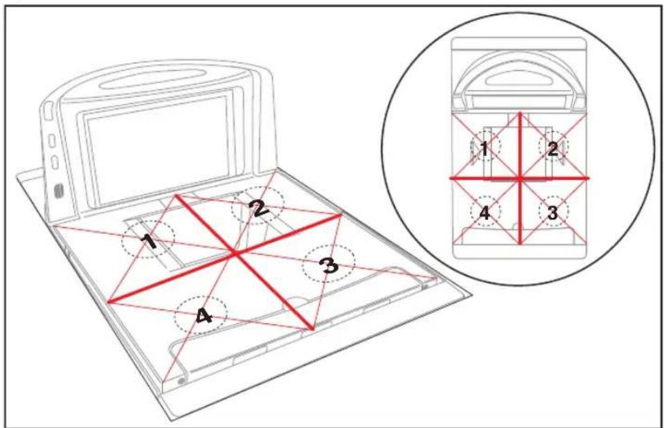
Increasing- Load Test (Phase 2)
After completing the Shift Test, you must complete the Increasing Load Test using 20.0, 25.0 and 30.0 pounds of weight.

NOTE
The upper limit of the scale is configurable according to POS interface type and may not necessarily be set at 30 pounds, which is the standard setting. For this test, continue to place weights in five pound increments only up to the upper weight limit set for your scale.
- With the scale starting at zero, place 20.0 pounds in the center of the weighing surface and check that the display reads between 19.99 and 20.01 lb.
- Place an additional five pounds in the center of the weighing surface, increasing the load to 25.0 pounds and check that the display reads between 24.99 and 25.01 lb.
- Place an additional five pounds in the center of the weighing surface increasing the load to 30.0 pounds and check that the display reads between 29.99 and 30.01 lb.
- Remove the weights and verify that the display reads 0.00.
Blanking Test
This test ensures that the scanner/scale will indicate its weighing capability has been exceeded if a weight greater than 0.05 pounds over its maximum upper weight limit is placed upon the unit.
- Place weights that total the upper weight limit plus 0.051 pounds on the scale. For example: If the upper limit is set at 30 pounds, place weights equaling 30.051 pounds.
- Verify that the display shows a dash and three hyphens (_ -- - ). This is the overweight indication.

NOTE
The scanner/scale may blank (show an underscore and three hyphens) at any weight greater than its upper limit, but must blank when the upper limit plus 0.051 pounds are set upon the weighing surface.
Decreasing-Load Test
This test ensures that the scanner/scale responds properly when a heavy object is followed by a significantly smaller object.
- Place a 30.0-pound load on the scale and verify that the display shows between 29.99 and 30.01 pounds.

If the upper weight limit for your scale is not set at 30 pounds, begin by placing weight equaling your upper limit setting.
-
Remove weights to leave 20 pounds on the scale. Check that the display shows between 19.99 and 20.01.
-
Remove another 15.0 pounds from the scale and check that the scale reads 5.00 lb.
-
You have completed the Decreasing Load Test.
Return to Zero Test
This test ensures that, after all other tests have been completed successfully, the scanner/scale returns to zero. Remove all weights from the scale and verify that the scale reads 0.00 lb.
After completing this test, close the calibration access cover and seal per local Weights and Measures requirements. This final step must agree with the legal requirements of your state or local government.
You have completed the calibration and verification process for weighing in pounds.
If the scanner/scale passes all these tests,
- Remove the weigh platter, install the calibration switch cover and install a seal (if required).
- Reinstall the weigh platter.
If the scanner/scale fails any of these tests, it should be serviced by a qualified technician.
Calibration Verification (Kilograms)
Once you have completed the calibration sequence, you may be required to perform these step-by-step verification procedures. These procedures follow the National Institute of Standards and Technology Handbook-44 guidelines for grocery scale installations. You may be required by state or local law to have these procedures performed by a certified technician or verified by a proper official.
These calibration verification procedures cover five different tests:
- Increasing-Load Test
- Shift Test
- Blanking Test
- Decreasing-Load Test
- Return to Zero Test
Increasing-Load Test (Phase 1)
This test checks Scale operation for increasing loads from 0.100 kg and 7.50 kg.
- Check that the display reads 0.000 kg when at rest with nothing on the weighing surface. (The Yellow LED is steadily lit).
- Place a 100 gram weight on the center of the weighing surface and check that the display reads 0.100 kg.
- Place an additional 200 grams on the center of the weighing surface and check that the display reads 0.300 kg.
- Place an additional 200 grams on the center of the weighing surface and check that the display reads 0.500 kg.
- Place an additional 100 grams on the center of the weighing surface and check that the display reads 0.600 kg.
- Place an additional 100 grams on the center of the weighing surface and check that the display reads 0.700 kg.
- Place an additional 100 grams on the center of the weighing surface and check that the display reads 0.800 kg.
-
Place an additional 200 grams on the center of the weighing surface and check that the display reads 1.000 kg.
-
Increase the weight on the scale to 7.50 kg on the center of the weighing surface and check that the display reads between 7.495 and 7.505 kg.
- Remove the weights and verify that the display reads 0.000 kg. You have completed the Increasing-Load Test (Phase 1).
Shift Test (Metric)
The Shift Test checks to ensure that items placed anywhere on the weighing surface of the scanner/scale are weighed properly. Refer to Figure 50 when performing this test.
- Place and remove in succession, a 5.0 kilogram load on the center of each of the four quadrants (2, 3, 4, and 5 in Figure 50) and in the center (1) of the scanner/scale's weighing platform. Verify that the display shows a reading of between 4.995 and 5.005 kg for each quadrant/center test and that the display returns to 0.000 between each load.
- After verifying the accuracy of each quadrant and the center of the weighing surface, remove all weight from the scale. You have completed the Shift Test.
Figure 50. European Shift Test (Metric)
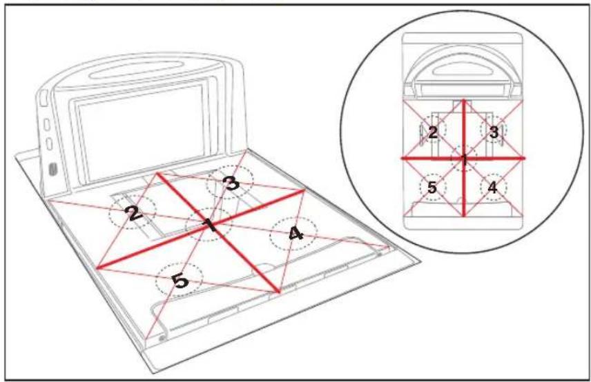
Increasing- Load Test (Phase 2)

NOTE
After completing the Shift Test, you must complete the Increasing Load Test using 10.00, 12.50 and 15 kilograms of weight.
The upper limit of the scale is configurable according to POS interface type and may not necessarily be set at 15 kilograms, which is the standard setting. For this test, continue to place weights in 2.50 kilogram increments only up to the upper weight limit set for your scale.
- Place 10.00 kilograms in the center of the weighing surface and check that the display reads between 9.990 kg and 10.010 kg.
- Place an additional 2.50 kilograms in the center of the weighing surface and check that the display reads between 12.490 kg and 12.510 kg.
- Place an additional 2.50 kilograms in the center of the weighing surface and check that the display reads between 14.990 kg and 15.010 kg.
- Remove the weights and verify that the display reads 0.000 kg.
- You have completed phase two of the increasing load test.
Blanking Test
This test ensures that the scanner/scale will indicate its weighing capability has been exceeded if a weight greater than 0.82 over its maximum upper weight limit is placed upon the unit.
- Place weights that total the upper limit plus 0.82 kilograms on the weigh platter. For example: If the upper limit is set at 15 kilograms, place weights equaling 15.82 kilograms.
- Verify that the display shows a dash and three hyphens ( _ -- -). This is the overweight indication.

NOTE
The scanner/scale may blank (show an underscore and three hyphens) at any weight greater than its upper limit, but must blank when the upper limit plus 0.82 pounds are set upon the weighing surface.
Decreasing-Load Test
This test ensures that the scanner/scale responds properly when a heavy object is followed by a significantly smaller object.
- Place weights that total 15.8 kilograms.

NOTE
If the upper weight limit for your scale is not set at 15 kilograms, begin by placing weight equaling your upper limit setting plus 0.8 kilograms.
- Remove weights to leave 10 kilograms on the scale and verify that the display shows between 9.990 and 10.010 kilograms.
- Remove an additional 9.00 kilograms from the scale and check that the scale reads 1.000 kg.
- You have completed the Decreasing Load Test.
Return to Zero Test
This test ensures that, after all other tests have been completed successfully, the scanner/scale returns to zero. Without any weight on the weigh platter, verify that the scale reads 0.000 kg.
You have completed the calibration and verification process for weighing in kilograms.
If the scanner/scale passes all these tests,
- Remove the weigh platter, install the calibration switch cover and install a seal (if required).
- Reinstall the weigh platter.
If the scanner/scale fails any of these tests, it should be serviced by a qualified technician.
Chapter 6
Programming
Introduction to Label Programming
The programming bar code labels contained in this manual will allow you to customize and configure features and settings for your scanner (scanner/scale). To ensure full compatibility and proper function, use only the programming bar codes in this manual and other product-specific publications to program scanner features.
This manual has been developed to make it quick and easy for users of all levels to find the information needed to understand and configure features. The following descriptions will help you to determine where to go from here.
Understanding the Basics
If you have little or no prior experience with programming using bar code labels, you should review the first few pages of this chapter to familiarize yourself with the basics of scanner programming before performing any changes to your configuration.
Integrating the Scanner With Your Host System
Your scanner MUST be equipped with the correct hardware (interface board, cable, etc.) to properly communicate with your host system. Contact your dealer for information if you have questions about your scanner's hardware compatibility.
You may also want to contact the dealer or your system administrator if you have no record of how your scanner was pre-programmed at the factory. Scanners are typically programmed with the default settings for specific interface types (see Appendix F, Factory
Defaults, for more information); however, your scanner may have been custom configured with settings that are unique to your company or application.
Once you know the scanner's current settings, you can determine what changes will be required to allow communication with your host system and/or optional features you choose to modify to customize your installation. After recording the modifications needed, finish reading this chapter, then turn to the appropriate page and follow the instructions to program the scanner.
When all scanner features are programmed to your satisfaction, the scanner is ready to be placed into operation.
Customizing Your Scanner's Operation
Most scanner programming falls within three general categories:
- General Scanner Features on page 106 — are features common to all interface types. Examples include beeper adjustments such as volume and length, read verification settings, etc.
- EAS Features on page 146 — control the settings for interfacing with the [optional] EAS device.
- Interface Related Features on page 148 — are the mandatory settings necessary to allow communication with your host terminal. Examples of these settings are: RS-232 baud rate and parity.

CAUTION
It is possible, via programming bar codes, to change the interface type (for example: from RS-232 to IBM Port 17). Great care should be taken to select the correct interface type, since you can cause damage to the scanner and/or POS terminal by attempting to change to an incompatible interface. ALWAYS make interface selections with the host cable DISCONNECTED.

Ensure that your planned modifications are compatible with the current interface. For example, baud rate selections are only valid in the RS-232 interface. The scanner will sound an error tone when scanning programming labels for features invalid to the current interface group.
- Symbology Programming on page 253 — gives the scanner the capability to autodiscriminate as few as one, and as many as all available symbologies. For optimal scanner performance enable only those symbologies required. Additionally the scanner may be programmed with the standard options available for the various symbologies, such as check digit, minimum label length, fixed and variable length bar codes, etc. If you experience difficulties, have questions or require additional information, contact your local distributor, or call your dealer or sales representative.
Programming Overview
The scanner's programmable feature settings can be modified to accommodate your system's unique requirements. These settings can be communicated to the scanner in one of three ways:
- Commands can be sent directly from the host. A limited set of host commands are available. Refer to Appendix D for more details or contact Tech Support.
- Programming bar code labels can also be used to modify the scanner's programmable settings. This manual provides the bar code labels and instructions necessary to configure the scanner's features and options.

NOTE
When you program the scanner using any of the methods above, the scanner will store the changes until reprogrammed or returned to factory defaults.
Programming via Handheld Device
The scanner can also accept programming via its auxiliary port using a handheld scanning device. Eligible handheld devices must have the ability to transmit Code 128 function codes such as the programming bar codes presented in this manual. Datalogic models QuickScan ^® 1000 and QuickScan ^® 6000 support this functionality. Handheld data format requirements (baud rate, parity, etc.) are presented in Appendix G of this manual. Additionally the programmable feature, Auxiliary Port Mode on page 118, must be set to “External Handheld Input” to allow operation.
What Is Programming Mode?
Programming Mode is a state in which the scanner must be placed in order to accept commands via programming bar code labels.
When programming using the bar code labels in this manual, the scanner is typically placed in Programming Mode by scanning the SWITCH label.
While in the Programming Mode, the scanner only recognizes ONLY the special programming bar codes contained in this programming guide. See Appendix A for information about scanner indications while in Programming Mode.
Entering and Exiting Programming Mode.
Use the bar code label below to enter and exit ('switch' into and out of) Programming Mode.

SWITCH LABEL
Programming Session
A typical programming session is conducted as follows:
- Scan the SWITCH bar code to place the scanner in Programming Mode. Depending upon its current programming, the scanner may emit a beep or beeps, indicating it has read the bar code and the scanner (top) green LED will flash on and off slowly while the scanner remains in Programming Mode. Normal scanning functions are disabled.
- Scan the programming bar code(s) that is (are) specially encoded to make the desired changes. With few exceptions ^1 , the scanner will emit a triple beep each time you scan a valid programming bar code.

NOTE
Not all features are available for all interfaces and the scanner will sound an error tone when scanning programming bar codes for features invalid to the current interface. Only features supported by the currently active interface will be implemented.

NOTE
If a bar code is scanned that changes the scanner's interface, all previous configuration items scanned in the programming session are lost.
Additionally, when programming a feature requiring you to scan single digits to set a multi-digit number, such as Minimum Label Length, scanning the SWITCH bar code (or any item tag/item value bar code) before completing all input will result in an error tone and cause the scanner to exit Programming Mode. Under these circumstances, the current feature you were trying to set is thrown out; any previous bar codes scanned during the session will take effect.

NOTE
It is recommended that programming sessions be limited to one feature at a time. Should you make a mistake in the programming sequence, it can be difficult to discover where an error has been made if several features are programmed at once. Additionally, it can be confusing to determine which features may or may not have been successfully set following such a session.
- Scan the SWITCH bar code to save any new settings and exit Programming Mode. The scanner will sound a beep and reset upon exiting Programming Mode, and the green LED will return to its usual state (on steady or off).
The scanner will exit Programming Mode under the following conditions:
— the programming sequence has been completed or the SWITCH bar code is scanned
— five minutes have passed without scanning activity. Any data programmed during the current session will be ignored ^1 , and the scanner will reset and revert to its condition previous to initiating the exited session.
— power is disconnected. Disconnecting power during Programming Mode, before scanning the SWITCH bar code, will cause all new settings to be ignored. On power-up, the scanner will return to previous settings.
-
Maintain a good record of all changes made to ensure that you know if the original factory settings have been changed.
-
Exception: If an interface bar code had been read while in Programming Mode, the scanner will operate on the default settings for the new interface.
Programming Sequence
To modify a scanner feature (item), the programming bar codes contained in this manual must be scanned in a given sequence depending upon the feature being programmed (as shown in Table 3). There are three possible programming sequences:

NOTE
If the scanner's interface type must be changed, always be sure that interface configuration is the FIRST item scanned during a programming session. (Selecting an interface type resets ALL other configuration items to the factory default for that interface type.)
A. Programming sample A (the most commonly used format) demonstrates how three bar codes are scanned in sequence to do the following:
-
Place the scanner in Programming Mode (SWITCH bar code).
-
Scan the Item Tag ^1 that will enable the new feature.
-
End the programming session and reset the scanner (SWITCH bar code).
B. Sample B provides an example of a programming feature requiring the entry of a range value. Like sample A, the scanner is placed in Programming Mode and an Item Tag ^1 is scanned. Then, a value must be entered before ending the programming session. In the example, three digits must be scanned from the number pad in Appendix C. This type of format, requiring several bar codes, is necessary to allow flexible programming for item values with larger numeric ranges.
C. The programming sequence shown in example C requires scanning of a single, extended length bar code. This special programming bar code contains all the data necessary to enter Programming Mode, set the Item Tag ^1 and Item Value, and exit Programming Mode (all in one step).
- An 'Item Tag" is a term used to describe an assigned number, which is encoded in a programming bar code, that toggles (selects, enables, disables, etc.) a specific programming feature.
Table 3. Programming Sequence

flowchart
graph TD
    A["SET"] --> B["ITEM TAG ITEM VALUE"]
    B --> C["END/RESET"]
    D["A"] --> E["1 SWITCH"]
    D --> F["2 ENABLE NEW FEATURE"]
    D --> G["3 SWITCH"]
    H["B"] --> I["1 SWITCH SWITCH"]
    H --> J["2 ENABLE NEW FEATURE USING THE FOLLOWING SETTINGS..."]
    H --> K["3 0 8"]
    L["C"] --> M["1 ONE BAR CODE CONTAINS SWITCH + ITEM TAG + ITEM VALUE + SWITCH"]
LED and Beeper Indicators
The scanner provides a set of indicators that verify/announce the various scanner functions.
If You Make a Mistake...
If, during a programming session, you find that you are unsure of the scanner's settings or wish to reset the scanner's configuration, use the Return to Factory Settings label below to return the scanner's configuration to the factory settings. Scanning this label will also reset any changes made during previous programming sessions.
Return to Factory Settings
Scan this bar code to return the scanner to the default settings configured at the factory for the currently active interface. This bar code is typically used to return the scanner to a "known" operating state when the present programming status is not known, faulty, or suspect.


Use this bar code with caution, since it will reset ALL features that may have been programmed since the scanner's installation.
DO NOT scan the SWITCH bar code before and after scanning this bar code, as the bar code below automatically enters and exits Programming Mode as a part of its function. If this bar code is scanned following a SWITCH bar code, it will simply cause the scanner to exit Programming Mode without making changes.

RETURN TO FACTORY SETTINGS
Test Mode
Use this feature to place the scanner into a testing, or “demo” mode. This special mode disables the scanner interface, meaning that bar code data is not sent out to the host via the scanner interface. This allows the bar code to be scanned continuously without requiring a response from the POS terminal.
To return the scanner to normal function, scan the TEST MODE = DISABLE on page 105 bar code below.

NOTE
DO NOT scan the SWITCH bar code before and after scanning the bar codes on this page.
Scanning the TEST MODE = DISABLE on page 105 bar code sets the Double Read Timeout to 600ms.

TEST MODE = DISABLE

TEST MODE = ENABLE
General Scanner Features
Scanner Button Options
Allows configuration of the scanner (volume) button to different modes of operation.
- Disable Scanner Button — Disables all button functions
- Enable Standard Functions — Enables volume, tone, and reset.
- Enable Reset Only — The button's sole function will be to reset the scanner.
To set this feature:
- Scan the SWITCH bar code.
- Scan your selection from the bar codes below. You'll need to cover any unused bar codes on this and the facing page to ensure that the scanner reads only the bar code you intend to scan.
- Complete the programming sequence by scanning the SWITCH bar code.

SCANNER BUTTON OPTIONS = DISABLE SCANNER BUTTON
Scanner Button Options (continued)
Remember to cover any unused bar codes on this and the facing page to ensure that the scanner reads only the bar code you intend to scan.


SCANNER BUTTON OPTIONS = ENABLE RESET ONLY
Double Read Timeout
The Double Read Timeout feature sets a time limit that determines how much time must pass before reading the same label again (e.g. two identical items in succession).
To set the Double Read Timeout:
- Scan the SWITCH bar code.
- Scan your selection from the bar codes below. You'll need to cover any unused bar codes on this and the facing page to ensure that the scanner reads only the bar code you intend to scan.
- Complete the programming sequence by scanning the SWITCH bar code.

If the incidence of multiple reads is not acceptable, increase the Double Read Timeout setting to a higher value.
NOTE

DOUBLE READ TIMEOUT = 400ms

DOUBLE READ TIMEOUT = 600ms
Double Read Timeout (continued)
Remember to cover any unused bar codes on this and the facing page to ensure that the scanner reads only the bar code you intend to scan.

DOUBLE READ TIMEOUT = 800ms
DOUBLE READ TIMEOUT = 1 SECOND
Laser Timeout
The laser timeout feature sets the time for switching the visible laser diodes (VLDs) off if the scanner is idle. Using this feature can prolong the life of the VLDs.
To set the Laser Timeout:
- Scan the SWITCH bar code.
- Scan your selection from the bar codes below. You'll need to cover any unused bar codes on this and the facing page to ensure that the scanner reads only the bar code you intend to scan.
- Complete the programming sequence by scanning the SWITCH bar code.

LASER TIMEOUT = 5 MINUTES
Laser Timeout (continued)
Remember to cover any unused bar codes on this and the facing page to ensure that the scanner reads only the bar code you intend to scan.

LASER TIMEOUT = 10 MINUTES

LASER TIMEOUT = 15 MINUTES
Motor Timeout

NOTE
The Motor Timeout feature sets the time for automatically switching the motor off when the scanner is not in use.
Laser safety requires that the laser switch off before the motor. If you set the motor timeout shorter than the laser timeout, the motor and the laser will both shut off when the motor timeout expires.
To set the Motor Timeout:
- Scan the SWITCH bar code.
- Scan your selection from the bar codes below. You'll need to cover any unused bar codes on this and the facing page to ensure that the scanner reads only the bar code you intend to scan.
- Complete the programming sequence by scanning the SWITCH bar code.
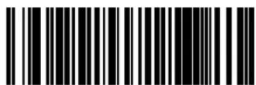
MOTOR TIMEOUT = 5 MINUTES
Motor Timeout (continued)
Remember to cover any unused bar codes on this and the facing page to ensure that the scanner reads only the bar code you intend to scan.

MOTOR TIMEOUT = 10 MINUTES

MOTOR TIMEOUT = 15 MINUTES
Motor Timeout (continued)
Remember to cover any unused bar codes on this and the facing page to ensure that the scanner reads only the bar code you intend to scan.

MOTOR TIMEOUT = 30 MINUTES
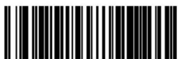
MOTOR TIMEOUT = 60 MINUTES
Label Gone Timeout
Specifies the amount of time that data segments are stored by the software before being discarded if a label has not been successfully decoded during the current “label in volume session,” which is defined as the time between when the label gone time is first started until the label gone timer expires.
To set the Label Gone Timeout:
- Scan the SWITCH bar code.
- Scan your selection from the bar codes below. You'll need to cover any unused bar codes on this and the facing page to ensure that the scanner reads only the bar code you intend to scan.
- Complete the programming sequence by scanning the SWITCH bar code.
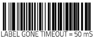
Label Gone Timeout (continued)
Remember to cover any unused bar codes on this and the facing page to ensure that the scanner reads only the bar code you intend to scan.

LABEL GONE TIMEOUT = 160 mS

LABEL GONE TIMEOUT = 250 mS
Label Gone Timeout (continued)
Remember to cover any unused bar codes on this and the facing page to ensure that the scanner reads only the bar code you intend to scan.

LABEL GONE TIMEOUT = 500 mS

LABEL GONE TIMEOUT = 1 Second
Auxiliary Port Mode
Selects the usage for the scanner's optional auxiliary port. The choices listed below are mutually exclusive (only one option can be active at a time).
• Disabled — Port is inactive
- External Handheld Input — Supports Datalogic ^ handheld scanners (QuickScan 1000, QuickScan 6000, PowerScan) as well as other models such as the Symbol ^ HotShot. Call your dealer for more information about supported devices.

NOTE
Cable pinout information for the Auxiliary Port is provided in Appendix B of this manual. A connected handheld scanner must be configured to transmit data as outlined in Appendix G.
- PIR/CT — PIR (Productivity Index Reporting) is a value-added feature which allows the scanner to provide information to an external computer indicating how easy the label was to read. CT (Checker Training) is also a value-added feature which allows the scanner to provide feedback to the cashier on how to scan in a more ergonomic fashion.
To set this feature:
- Scan the SWITCH bar code.
- Scan your selection from the bar codes below. You'll need to cover any unused bar codes on this and the facing page to ensure that the scanner reads only the bar code you intend to scan.
- Complete the programming sequence by scanning the SWITCH bar code.

AUXILIARY PORT MODE = DISABLE
Auxiliary Port Mode (continued)
Remember to cover any unused bar codes on this and the facing page to ensure that the scanner reads only the bar code you intend to scan.

AUXILIARY PORT MODE = EXTERNAL HANDHELD INPUT

AUXILIARY PORT MODE = PIR/CT
Auxiliary Port Baud Rate
Specifies the baud rate of the auxiliary port when operating in PIR/CT mode.

NOTE
PIR/CT is a value-added feature which may not have been activated on your model.
To specify the Auxiliary Port Baud Rate:
- Scan the SWITCH bar code.
- Scan the desired baud rate from the bar codes below and on the immediately following pages. You'll need to cover any unused bar codes on this and the facing page to ensure that the scanner reads only the bar code you intend to scan.
- Complete the programming sequence by scanning the SWITCH bar code.


Auxiliary Port Baud Rate (continued)
Remember to cover any unused bar codes on this and the facing page to ensure that the scanner reads only the bar code you intend to scan.

RS-232 BAUD RATE = 4800

RS-232 BAUD RATE = 9600
Auxiliary Port Baud Rate (continued)
Remember to cover any unused bar codes on this and the facing page to ensure that the scanner reads only the bar code you intend to scan.


Auxiliary Port Baud Rate (continued)
Remember to cover any unused bar codes on this and the facing page to ensure that the scanner reads only the bar code you intend to scan.

RS-232 BAUD RATE = 57600

RS-232 BAUD RATE = 115200
Laser Failure Mode
This configuration item selects whether the scanner should continue operating if only one laser is functional. (The scanner has two lasers: One for the horizontal window, and one for the vertical window.) Options for this feature are:
- Single Laser Failure OK — The scanner can still operate even if one laser is no longer functional. In this mode the scanner will read only from the window associated with the operational laser. This provides the user the ability to continue working until the unit is serviced. The 7-segment display will show the error code for the failed laser (reference Chapter 4, Error Codes), but the scanner will continue to function.
- Single Laser Failure Fatal — If it is desirable to have maximum performance or nothing at all, Laser Failure Mode should be selected as fatal. Upon single laser failure, the scanner will sound an error tone and cease scanning functions until serviced.
To set this feature:
- Scan the SWITCH bar code.
- Scan your selection from the bar codes below. You'll need to cover any unused bar codes on this and the facing page to ensure that the scanner reads only the bar code you intend to scan.
- Complete the programming sequence by scanning the SWITCH bar code.


Productivity Index Reporting (PIR)/Cashier Training (CT)
When PIR/CT is enabled, label quality data is appended to decoded data before being presented to the POS. The PIR feature allows the scanner to provide information to an external computer indicating how easy the label was to read. CT allows the scanner to provide feedback to the cashier on how to scan in a more ergonomic fashion.

NOTE
This value-added feature is a factory-programmed option. Contact your dealer for information about upgrading your system to include this advanced capability.
To set this feature:
- Scan the SWITCH bar code.
- Scan your selection from the bar codes below. You'll need to cover any unused bar codes on this and the facing page to ensure that the scanner reads only the bar code you intend to scan.
- Complete the programming sequence by scanning the SWITCH bar code.
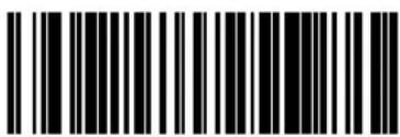
PIR/CT = DISABLE

PIR/CT = ENABLE
Indication Features
Green LED Idle State
This feature specifies the state of the green scanner LED when the scanner is idle and ready to read a label. Options are:
- Off
. O n d i m
To set the LED Idle State:
- Scan your selection from the bar codes below. You'll need to cover any unused bar codes on this and the facing page to ensure that the scanner reads only the bar code you intend to scan.
- Complete the programming sequence by scanning the SWITCH bar code.

GREEN LED IDLE STATE = OFF
GREEN LED IDLE STATE = ON DIM
Power-up Beep Control
Specifies the type of audible indication that is made when entering scanner-active mode on power-up. Choices are:
• N o b e e p
- One beep
- Three beeps
To set the Power-up Beep:
- Scan the SWITCH bar code.
- Scan your selection from the three bar codes below. You'll need to cover any unused bar codes on this and the facing page to ensure that the scanner reads only the bar code you intend to scan.
- Complete the programming sequence by scanning the SWITCH bar code.

POWER-UP BEEP = OFF

POWER-UP BEEP = ONE BEEP
Good Read Beep Control
This feature enables/disables scanner beep upon successfully decoding of a label.
To set this feature:
- Scan the SWITCH bar code.
- Scan your selection from the two bar codes below. You'll need to cover any unused bar codes on this and the facing page to ensure that the scanner reads only the bar code you intend to scan.
- Complete the programming sequence by scanning the SWITCH bar code.

GOOD READ BEEP = DISABLE

GOOD READ BEEP = ENABLE
Good Read Beep Frequency
Adjusts the scanner's good read beep to sound at low, medium, or high frequency (controls the beeper's pitch/tone).
- Low = 660 Hz
• Medium = 860 Hz - High = 1050 Hz
To set the Good Read Beep Frequency:
- Scan the SWITCH bar code.
- Scan your selection from the three bar codes below. You'll need to cover any unused bar codes on this and the facing page to ensure that the scanner reads only the bar code you intend to scan.
- Complete the programming sequence by scanning the SWITCH bar code.
GOOD READ BEEP FREQUENCY = LOW
Good Read Beep Frequency (continued)
Remember to cover any unused bar codes on this and the facing page to ensure that the scanner reads only the bar code you intend to scan.


GOOD READ BEEP FREQUENCY = HIGH
Good Read Beep Length
Specifies the duration of a good read beep.
To set the good read beep length:
- Scan the SWITCH bar code.
-
Scan the bar code, SET GOOD READ BEEP LENGTH on page 131. You'll need to cover any unused bar codes on this and the facing page to ensure that the scanner reads only the bar code you intend to scan.
-
Scan the appropriate digits from the keypad in Appendix C that represent the desired good read beep length setting. The selectable range is 1–255, which is the timeout in 10-millisecond increments. Pad all single and double digit numbers with leading zeroes to yield a three-digit entry (001–255).
Examples:
$$ \begin{array}{l} 0 0 1 = 1 0 \mathrm{ms} \ 0 0 5 = 5 0 \mathrm{ms} \ 0 4 0 = 4 0 0 \mathrm{ms} \ 2 5 0 = 2, 5 0 0 \mathrm{ms} (2. 5 \text { seconds }) \ \end{array} $$
- The scanner will automatically exit Programming Mode when the appropriate amount of digits have been scanned

Good Read Beep Volume
Selects the beeper volume upon a good read beep. There are five selectable volumes, with each volume increment adding approximately five decibels to the previous level:
$$ \begin{array}{l} \cdot \quad 0 = \text { L o w e s t V o l u m e } \ \cdot 1 = \text { M e d i u m } - \text { L o w V o l u m e } \ \cdot 2 = \text { M e d i u m V o l u m e } \ \cdot 3 = \text { H i g h e s t V o l u m e } \ \end{array} $$
To set the Good Read Beep Volume:
- Scan the SWITCH bar code.
- Scan your selected volume bar code from this or the following pages. You'll need to cover any unused bar codes on this and the facing page to ensure that the scanner reads only the bar code you intend to scan.
- Complete the programming sequence by scanning the SWITCH bar code.

GOOD READ BEEP VOLUME = LOWEST
Good Read Beep Volume (continued)
Remember to cover any unused bar codes on this and the facing page to ensure that the scanner reads only the bar code you intend to scan.
GOOD READ BEEP VOLUME = MEDIUM LOW

GOOD READ BEEP VOLUME = MEDIUM
Good Read Beep Volume (continued)
Remember to cover any unused bar codes on this and the facing page to ensure that the scanner reads only the bar code you intend to scan.

Good Read When to Indicate
This feature specifies when the scanner will provide indication (beep and/or flash its green LED) upon successfully reading a bar code.
• Good Read = Indicate after decode
• Good Read = Indicate after transmit
- Good Read = Indicate after CTS goes inactive, then active

NOTE
The "Indicate after CTS goes inactive..." mode applies to RS-232 STD and RS-232 WN interfaces only. If set to this mode in other interfaces, "Indicate after decode" mode will be implemented.
To set the Good Read When to Indicate feature:
- Scan the SWITCH bar code.
- Scan the desired mode bar code from this page. You'll need to cover any unused bar codes on this and the facing page to ensure that the scanner reads only the bar code you intend to scan.
- Complete the programming sequence by scanning the SWITCH bar code.
GOOD READ = INDICATE AFTER DECODE
Good Read When to Indicate (continued)
Remember to cover any unused bar codes on this and the facing page to ensure that the scanner reads only the bar code you intend to scan.
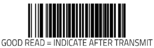

GOOD READ = INDICATE AFTER CTS GOES INACTIVE, THEN ACTIVE
(RS-232 ONLY)
Scale Features
Scale Enable

NOTE
Use this feature to enable or disable scale operation.
Recalibration/recertification may be required when adding scale functionality. Consult your local Weights and Measures authority.
If this feature is enabled the scanner will expect that it is to function as a scanner-scale, and will indicate an error if it is not a scale-equipped unit. See Chapter 4, Error Codes, for more information.
To set this feature:
- Scan the SWITCH bar code.
- Scan your selection from the two bar codes below. You'll need to cover any unused bar codes on this and the facing page to ensure that the scanner reads only the bar code you intend to scan.
- Complete the programming sequence by scanning the SWITCH bar code.

SCALE = DISABLE

SCALE = ENABLE
Scale Enforced Zero Return
This feature enables/disables the enforced zero return of the scale. Three settings are available for this feature:
- Dis a b l e
- Scale Must Return to Zero Weight Within Two Minutes — Scale will require re-zeroing if a non-zero weight is left on for more than two minutes or if the scale is below zero.
- Scale Must Return to Zero Weight Between Weight Requests — Re-zeroing is required if weight doesn't return to zero between weight requests from the POS, plus scale will require re-zeroing if a non-zero weight is left on for more than two minutes or if the scale is below zero.
- Non-Zero for Two Minutes — Re-zeroing is required if weight does not return to zero within two minutes.
To set this feature:
- Scan the SWITCH bar code.
- Scan your selection from the bar codes below. You'll need to cover any unused bar codes on this and the facing page to ensure that the scanner reads only the bar code you intend to scan. The strategy is to select the lowest possible filter level needed that allows normal scale operation.
- Complete the programming sequence by scanning the SWITCH bar code.

SCALE ENFORCED ZERO RETURN = DISABLE
Scale Enforced Zero Return (continued)
Remember to cover any unused bar codes on this and the facing page to ensure that the scanner reads only the bar code you intend to scan.

SCALE ENFORCED ZERO RETURN =
NON-ZERO FOR 2 MINUTES OR BELOW ZERO

SCALE ENFORCED ZERO RETURN = NON-ZERO FOR 2 MINUTES OR BELOW ZERO
OR NO ZERO BETWEEN WEIGHTS
Scale Enforced Zero Return (continued)
Remember to cover any unused bar codes on this and the facing page to ensure that the scanner reads only the bar code you intend to scan.

Scale Interface Type
Use this feature to select the scale interface type. Choices are:
- No Scale Interface
• RS-232 — SASI - RS-232 — ICL
To set the Scale Interface Type:
- Scan the SWITCH bar code.
- Scan your selection from the bar codes below. You'll need to cover any unused bar codes on this and the facing page to ensure that the scanner reads only the bar code you intend to scan.
- Complete the programming sequence by scanning the SWITCH bar code.

SCALE INTERFACE TYPE = NO SCALE INTERFACE

SCALE INTERFACE TYPE = RS-232 — SASI
Scale Interface Type (continued)
Remember to cover any unused bar codes on this and the facing page to ensure that the scanner reads only the bar code you intend to scan.
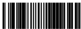
SCALE INTERFACE TYPE = RS-232 — ICL
Scale Calibration Notification
When enabled, this feature allows the host to be notified of a calibration event.
To set this feature:
- Scan the SWITCH bar code.
- Scan your selection from the two bar codes below. You'll need to cover any unused bar codes on this and the facing page to ensure that the scanner reads only the bar code you intend to scan.
- Complete the programming sequence by scanning the SWITCH bar code.

SCALE CALIBRATION NOTIFICATION = DISABLE

SCALE CALIBRATION NOTIFICATION = ENABLE
Scale Intercharacter Delay
Sets the delay between the end of one character and the beginning of the next, in 10 millisecond increments.
To specify the intercharacter delay:
- Scan the SWITCH bar code.
- Scan the bar code below, SET KEYBOARD WEDGE INTERCHARACTER DELAY on page 252. You'll need to cover any unused bar codes on this and the facing page to ensure that the scanner reads only the bar code you intend to scan.
- Scan the appropriate digits from the keypad in Appendix C that represent the desired delay. The selectable range is 0–100, which is the delay in 10–millisecond increments. Pad all single and double digit numbers with leading zeroes to yield a three-digit entry (000–100).
Examples: - The scanner will automatically exit Programming Mode when the appropriate amount of digits have been scanned.
$$ \begin{array}{l} 0 0 1 = 1 0 \mathrm{ms} \ 0 0 5 = 5 0 \mathrm{ms} \ 0 4 0 = 4 0 0 \mathrm{ms} \ 1 0 0 = 1, 0 0 0 \mathrm{ms} (1 \text { second }) \ \end{array} $$

SCALE INTERCHARACTER DELAY
Remote Display — Enable/Disable
The scanner-scale can be configured to operate with or without a Remote Display.

NOTE
Recalibration/recertification may be required when adding a Remote Display. Consult your local Weights and Measures authority.
If this feature is enabled the scanner-scale will expect that it is connected to a Remote Display, and will indicate an error if one is not. See Chapter 4, Error Codes, for more information.

REMOTE DISPLAY = DISABLE

EAS Features
EAS Active State
Specifies the active state polarity of EAS (Electronic Article Surveillance); the inactive state is its opposite polarity. EAS output goes active during the good read indication of a bar code, allowing the EAS device to deactivate a tag on the product.
To set the EAS Active State:
- Scan the SWITCH bar code.
- Scan your selection from the bar codes below. You'll need to cover any unused bar codes on this and the facing page to ensure that the scanner reads only the bar code you intend to scan.
- Complete the programming sequence by scanning the SWITCH bar code.

EAS ACTIVE STATE = ACTIVE LOW
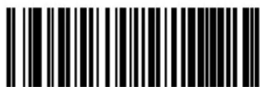
EAS ACTIVE STATE = ACTIVE HIGH
EAS Timeout
Specifies the amount of time that an EAS (Electronic Article Surveillance) signal is held in its active state for a good read indication.
To set the EAS Timeout:
-
Scan the SWITCH bar code.
-
Scan the bar code, SET EAS TIMEOUT on page 147 below. You'll need to cover any unused bar codes on this and the facing page to ensure that the scanner reads only the bar code you intend to scan.
-
Scan the appropriate digits from the keypad in Appendix C that represent the desired EAS Timeout duration. The selectable range is 0–255, which is the timeout in 10-millisecond increments. Pad all single and double digit numbers with leading zeroes to yield a three-digit entry (000–255).
Examples:
000 = EAS timeout disabled
001 = 10ms
005 = 50ms
040 = 400ms
250 = 2,500ms (2.5 seconds)

NOTE
A setting of 0 (000) disables this feature.
- Scan the SWITCH bar code to exit Programming Mode.

SET EAS TIMEOUT
Interface Related Features
Interface Type
Specifies the current scanner interface. Selections are:
| INTERFACE (I/F) TYPE | I/F I.D. NUMBERa |
| RS-232 Standard | 05 |
| RS-232 Wincor-Nix-dorf | 12 |
| RS-232 Single Cable | 20 |
| OEM USB | 45 |
| IBM Port 17 | 04 |
| IBM Port 5B | 08 |
| IBM Port 9B | 23 |
| USB Keyboard | 35 |
| NOT USER-SELECTABLE Keyboard | |
| Null Interface | 7-segment FRU display indi-cates 0 at start-up (accompa-nied by trill beep for approx. 2 seconds) |
| INTERFACE (I/F) TYPE | I/F I.D. NUMBERa |
| Keyboard Wedge A | 25 |
| Keyboard Wedge B | 26 |
| Keyboard Wedge C | 27 |
| Keyboard Wedge D | 28 |
| Keyboard Wedge E | 29 |
| Keyboard Wedge F | 2A |
| Keyboard Wedge G | 31 |
| Keyboard Wedge H | 32 |
| Keyboard Wedge I | 33 |
| Wedge J | 34 |
a. To access a scanner's interface identification number, place the scanner in Scanner Diagnostic Mode and view the 7-segment FRU display (reference Chapter 2, Scanner Diagnostic Mode, for more information).
Interface Type (continued)

NOTE
A new scanner may have been shipped from the factory with a Null Interface (no interface type selected) to ensure system compatibility at installation. In this case, the correct Interface Type programming bar code must be scanned first before the scanner can be used with a POS system.

NOTE
If the scanner's interface type must be changed, always be sure that interface configuration is the FIRST item scanned during a programming session. (Selecting an interface type resets ALL other configuration items to the factory default for that interface type.)
To select the desired interface:

CAUTION
Great care should be taken to select the correct interface type, since you can cause damage to the scanner and/or POS terminal by attempting to change to an incompatible interface. ALWAYS make interface selections with the host cable DISCONNECTED.

NOTE
When an interface is selected, the scanner loads the factory configuration for that interface as the selection is made, erasing any and all custom configuration that may have previously been done.
- Disconnect current interface cable(s) if currently connected.
- Scan the SWITCH bar code
- Scan the bar code representing the appropriate interface located on the following pages. You'll need to cover any unused bar codes adjacent to and on any facing pages to ensure the scanner reads only the bar code you intend to scan.
- Complete the programming sequence by scanning the SWITCH bar code.

NOTE
Once the correct interface has been set, it will be necessary to proceed to the appropriate pages in this manual that select parameters and options for that interface. For example, if RS-232 is selected, turn to the pages in this manual headed as features specific to the RS-232 interface.
- Connect new interface cable(s).

RS-232 Interface Selection
Remember to cover any unused bar codes on this and the facing page to ensure that the scanner reads only the bar code you intend to scan.
Great care should be taken to select the correct interface type, since you can cause damage to the scanner and/or POS terminal by attempting to change to an incompatible interface. ALWAYS make interface selections with the host cable DISCONNECTED.

INTERFACE TYPE = RS-232 STANDARD
RS-232 Wincor-Nixdorf Interface Selection
Remember to cover any unused bar codes on this and the facing page to ensure that the scanner reads only the bar code you intend to scan.

Great care should be taken to select the correct interface type, since you can cause damage to the scanner and/or POS terminal by attempting to change to an incompatible interface. ALWAYS make interface selections with the host cable DISCONNECTED.

INTERFACE TYPE = RS-232 WINCOR-NIXDORF

RS-232 Single Cable Interface Selection
Remember to cover any unused bar codes on this and the facing page to ensure that the scanner reads only the bar code you intend to scan.
Great care should be taken to select the correct interface type, since you can cause damage to the scanner and/or POS terminal by attempting to change to an incompatible interface. ALWAYS make interface selections with the host cable DISCONNECTED.

Single cable installations require connection at the POS Terminal (host) port. The Scale Host port connection is not used for this interface.
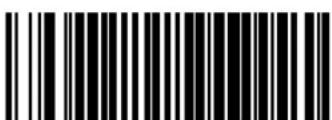
INTERFACE TYPE = RS-232 SINGLE CABLE
OEM USB Interface Selection
Remember to cover any unused bar codes on this and the facing page to ensure that the scanner reads only the bar code you intend to scan.

Great care should be taken to select the correct interface type, since you can cause damage to the scanner and/or POS terminal by attempting to change to an incompatible interface. ALWAYS make interface selections with the host cable DISCONNECTED.

Single cable installations require connection at the POS Terminal (host) port. The Scale Host port connection is not used for this interface.
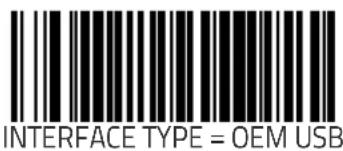

CAUTION

NOTE
IBM Port 17 Interface Selection
Remember to cover any unused bar codes on this and the facing page to ensure that the scanner reads only the bar code you intend to scan.
Great care should be taken to select the correct interface type, since you can cause damage to the scanner and/or POS terminal by attempting to change to an incompatible interface. ALWAYS make interface selections with the host cable DISCONNECTED.
Single cable installations require connection at the POS Terminal (host) port. The Scale Host port connection is not used for this interface.

INTERFACE TYPE = IBM PORT 17
IBM Port 5B Interface Selection
Remember to cover any unused bar codes on this and the facing page to ensure that the scanner reads only the bar code you intend to scan.

CAUTION
Great care should be taken to select the correct interface type, since you can cause damage to the scanner and/or POS terminal by attempting to change to an incompatible interface. ALWAYS make interface selections with the host cable DISCONNECTED.
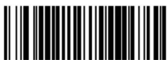
INTERFACE TYPE = IBM PORT 5B

IBM Port 9B Interface Selection
Remember to cover any unused bar codes on this and the facing page to ensure that the scanner reads only the bar code you intend to scan.
Great care should be taken to select the correct interface type, since you can cause damage to the scanner and/or POS terminal by attempting to change to an incompatible interface. ALWAYS make interface selections with the host cable DISCONNECTED.
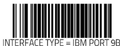
USB Keyboard Interface Selection
Remember to cover any unused bar codes on this and the facing page to ensure that the scanner reads only the bar code you intend to scan.

Great care should be taken to select the correct interface type, since you can cause damage to the scanner and/or POS terminal by attempting to change to an incompatible interface. ALWAYS make interface selections with the host cable DISCONNECTED.

INTERFACE TYPE = USB KEYBOARD

Keyboard Wedge A Interface Selection
Remember to cover any unused bar codes on this and the facing page to ensure that the scanner reads only the bar code you intend to scan.
Great care should be taken to select the correct interface type, since you can cause damage to the scanner and/or POS terminal by attempting to change to an incompatible interface. ALWAYS make interface selections with the host cable DISCONNECTED.

INTERFACE TYPE = KEYBOARD WEDGE A
Keyboard Wedge B Interface Selection
Remember to cover any unused bar codes on this and the facing page to ensure that the scanner reads only the bar code you intend to scan.

Great care should be taken to select the correct interface type, since you can cause damage to the scanner and/or POS terminal by attempting to change to an incompatible interface. ALWAYS make interface selections with the host cable DISCONNECTED.
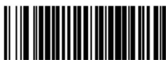
INTERFACE TYPE = KEYBOARD WEDGE B

Keyboard Wedge C Interface Selection
Remember to cover any unused bar codes on this and the facing page to ensure that the scanner reads only the bar code you intend to scan.
Great care should be taken to select the correct interface type, since you can cause damage to the scanner and/or POS terminal by attempting to change to an incompatible interface. ALWAYS make interface selections with the host cable DISCONNECTED.

INTERFACE TYPE = KEYBOARD WEDGE C
Keyboard Wedge D Interface Selection
Remember to cover any unused bar codes on this and the facing page to ensure that the scanner reads only the bar code you intend to scan.

Great care should be taken to select the correct interface type, since you can cause damage to the scanner and/or POS terminal by attempting to change to an incompatible interface. ALWAYS make interface selections with the host cable DISCONNECTED.

INTERFACE TYPE = KEYBOARD WEDGE D

Keyboard Wedge E Interface Selection
Remember to cover any unused bar codes on this and the facing page to ensure that the scanner reads only the bar code you intend to scan.
Great care should be taken to select the correct interface type, since you can cause damage to the scanner and/or POS terminal by attempting to change to an incompatible interface. ALWAYS make interface selections with the host cable DISCONNECTED.

INTERFACE TYPE = KEYBOARD WEDGE E
Keyboard Wedge F Interface Selection
Remember to cover any unused bar codes on this and the facing page to ensure that the scanner reads only the bar code you intend to scan.

CAUTION
Great care should be taken to select the correct interface type, since you can cause damage to the scanner and/or POS terminal by attempting to change to an incompatible interface. ALWAYS make interface selections with the host cable DISCONNECTED.

INTERFACE TYPE = KEYBOARD WEDGE F

Keyboard Wedge G Interface Selection
Remember to cover any unused bar codes on this and the facing page to ensure that the scanner reads only the bar code you intend to scan.
Great care should be taken to select the correct interface type, since you can cause damage to the scanner and/or POS terminal by attempting to change to an incompatible interface. ALWAYS make interface selections with the host cable DISCONNECTED.
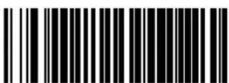
INTERFACE TYPE = KEYBOARD WEDGE G
Keyboard Wedge H Interface Selection
Remember to cover any unused bar codes on this and the facing page to ensure that the scanner reads only the bar code you intend to scan.

Great care should be taken to select the correct interface type, since you can cause damage to the scanner and/or POS terminal by attempting to change to an incompatible interface. ALWAYS make interface selections with the host cable DISCONNECTED.

INTERFACE TYPE = KEYBOARD WEDGE H

Keyboard Wedge I Interface Selection
Remember to cover any unused bar codes on this and the facing page to ensure that the scanner reads only the bar code you intend to scan.
Great care should be taken to select the correct interface type, since you can cause damage to the scanner and/or POS terminal by attempting to change to an incompatible interface. ALWAYS make interface selections with the host cable DISCONNECTED.
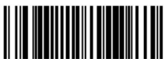
INTERFACE TYPE = KEYBOARD WEDGE I
Keyboard Wedge J Interface Selection
Remember to cover any unused bar codes on this and the facing page to ensure that the scanner reads only the bar code you intend to scan.

CAUTION
Great care should be taken to select the correct interface type, since you can cause damage to the scanner and/or POS terminal by attempting to change to an incompatible interface. ALWAYS make interface selections with the host cable DISCONNECTED.
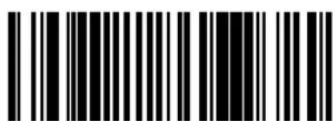
INTERFACE TYPE = KEYBOARD WEDGE J
Maximum Host-Transmitted Message Length
Specifies the maximum number of data characters allowed in messages transmitted to the host.
To set the Maximum Host–Transmitted Message Length:
- Scan the SWITCH bar code.
- Scan the bar code, SET MAXIMUM HOST-TRANSMITTED MES-SAGE LENGTH on page 168 below. You'll need to cover any unused bar codes on this and the facing page to ensure that the scanner reads only the bar code you intend to scan.
- Scan the appropriate digits from the keypad in Appendix C that represent the desired maximum host-transmitted message length. The selectable range is 0–249 data characters. (Labels that are longer than this length are not read.) Pad all single and double digit numbers with leading zeroes to yield a three-digit entry (000–249).

NOTE
If this configuration item is set to 0 (000), there is no general length limit imposed on data being transmitted to the host.
- The scanner will automatically exit Programming Mode when the appropriate amount of digits have been scanned

SET MAXIMUM HOST-TRANSMITTED MESSAGE LENGTH
Number of Host Transmission Buffers
Specifies the number of host transmission(s) that may be buffered. By buffering data from a bar code, the scanner can continue to read a new bar code while the old one is being transmitted to the host.
Selecting BUFFERS = 1 means that the first bar code must be transmitted before a new one can be read. A selection of BUFFERS = 2 means that a new bar code can be read while data from the first bar code is transmitted. When the feature, Good Read Beep Control on page 128, is enabled, the scanner will beep when the data is placed in a transmission buffer.
When a DISABLE SCANNER command is received from the host, the scanner will continue to transmit all data that is buffered.
To select the Number of Host Transmission Buffers:
- Scan the SWITCH bar code.
- Scan bar code below representing the desired setting. You'll need to cover any unused bar codes on this and the facing page to ensure that the scanner reads only the bar code you intend to scan.
- Complete the programming sequence by scanning the SWITCH bar code.


AIM ID
AIM label identifiers (as opposed to custom characters you select yourself as with label identifiers) can be included with scanned bar code data. AIM label identifiers consist of three characters as follows:
- A close brace character (ASCII ‘]’), followed by...
• A code character (see the table below), followed by
- A modifier character (the modifier character is symbol dependent)
| SYMBOLOGY CHAR SYMBOLOGY CHAR | |||
| UPC/EAN | E | MSI/Plossey | M |
| Code 39 | A | PDF 417 | L |
| Codabar | F | DataBar Omnidirec-tional, DataBar Expanded (RSS) | e |
| Interleaved.2 of 5 | I | Standard 2 of 5 | S |
| Code 93 | G | ISBN | X^a |
| Code 128/EAN 128 | C | ||
a. ISBN (X with a 0 modifier character)
Figure 51. AIM ID

AIM ID (continued)
Remember to cover any unused bar codes on this and the facing page to ensure that the scanner reads only the bar code you intend to scan.

AIM ID: DISABLE

AIM ID: ENABLE
Label ID Control

A Label ID is used to identify a barcode (symbology) type. See Appendix D, Default Settings, for a listing for common symbologies. It can be appended previous to or following the transmitted barcode data depending upon how this option is enabled. This feature provides options for configuring custom Label IDs individually per symbology. If you wish to program the scanner to always include an industry standard label identifier for ALL symbology types, see the previous feature, AIM ID.
The Label ID is a customizable code of up to three ASCII characters (each of which are 00-FF) followed by a control character (00-01), This control character, when set to zero, does nothing. When set to one, it appends the symbology's AIM ID to the Label ID.
When the control character is set to 01 for UPC-A and UPC-E, it expands the label to EAN-13 and thus follows the EAN-13 Label ID settings.
Label IDs cannot be modified when using the OEM-USB interface.
To configure a Label ID:
- Scan the START barcode.
- Select Label ID position as either BEFORE or AFTER by scanning the appropriate barcode.
- Determine the desired character(s) (you may choose up to three) which will represent the Label ID for the selected symbology. Next, turn to the ASCII Chart on the inside back cover of this manual and find the equivalent hex digits associated with your choice of Label ID. For example, the default Label ID for Code 39 for the Single Cable RS-232 interface is 'B' '1'. To change it to 'R' '4', the following should be performed:
- Scan the Switch label
- Scan the 'Set Code 39 Label ID' label
- Scan '5'
- Scan '2'
- Scan '3'
Label ID Control (continued)
- Scan 4'
- Scan '0'
- Scan '0'
- Scan '0'
- Scan '0'
- Scan the Switch label
Figure 52. Label ID Position Options
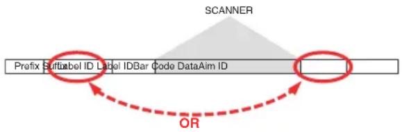
flowchart
graph TD
    A["SCANNER"] --> B["Prefix SuffixLabel ID Label IDBar code DataAim ID"]
    B --> C["OR"]
    C --> D["Arrow to SuffixLabel ID Label IDBar code DataAim ID"]
    D --> E["Arrow to OR"]
Remember to cover any unused bar codes on this and the facing page to ensure that the scanner reads only the bar code you intend to scan.


Label ID Control (continued)
Remember to cover any unused bar codes on this and the facing page to ensure that the scanner reads only the bar code you intend to scan.

LABEL ID TRANSMISSION: AFTER BAR CODE DATA
Global Prefix
This feature specifies the prefix that is added to beginning of label transmission.
To specify the Global Prefix Character(s):
- Scan the SWITCH bar code.
- Scan the bar code, SET GLOBAL PREFIX on page 176 below. You'll need to cover any unused bar codes to ensure the scanner reads only the bar code you intend to scan.
- Scan the appropriate characters/digits from the keypad in Appendix C that represent the hex designation for the desired character(s). A table containing the ASCII Character Set on page 1 and their corresponding Hex Values is available in the inside back cover of this manual. ASCII parameters must be input by scanning a pair of hexadecimal digits for each character. Thus, to set a two-character value of AB, bar codes containing the digits '4', '1', '4', and '2' must be scanned. The selectable range for this option is any hex value from 00 to FF. Up to 20 hex pairs can be designated.

NOTE
To specify "no Global Prefix," scan 00.
-
If designating the full 20 hex pairs, the scanner will automatically exit Programming Mode when the appropriate amount of digits have been scanned. If designating less than 20 hex pairs, you can end the programming sequence early by scanning the TERMINATE SEQUENCE on page 176 bar code.
-
Complete the programming sequence by scanning the SWITCH bar code.
Global Prefix (continued)
Remember to cover any unused bar codes on this and the facing page to ensure that the scanner reads only the bar code you intend to scan.

SET GLOBAL PREFIX

TERMINATE SEQUENCE
Global Suffix
This feature specifies the suffix that is added to end of a label transmission. Three standard options are available below. Contact your dealer for other alternate settings for this feature.
- No Global Suffix
- CR — Carriage Return
• CR LF — Carriage Return, Line Feed
To set the Global Suffix:
- Scan the SWITCH bar code.
- Scan your selection from the bar codes below.
- Complete the programming sequence by scanning the SWITCH bar code.
GLOBAL SUFFIX = NO GLOBAL SUFFIX
Global Suffix (continued)
Remember to cover any unused bar codes on this and the facing page to ensure that the scanner reads only the bar code you intend to scan.

GLOBAL SUFFIX = CR

GLOBAL SUFFIX = CR LF
Case Conversion
Changes the case of all alphabetic characters to upper or lower case.
Choices are:
| No case conversion |
| U p p e r c a s e |
| L o w e r c a s e |
To configure this feature:
-
Scan the SWITCH bar code.
-
Scan your selection from the case conversion bar codes below. You'll need to cover any unused bar codes on this and the facing page to ensure that the scanner reads only the bar code you intend to scan.
-
Complete the programming sequence by scanning the SWITCH bar code.

CASE CONVERSION = NO CASE CONVERSION
Case Conversion (continued)
Remember to cover any unused bar codes on this and the facing page to ensure that the scanner reads only the bar code you intend to scan.

CASE CONVERSION = LOWER CASE
IBM Features
IBM Interface Options
IBM interfaces offer specific control over interaction with certain devices.

NOTE
The OEM USB interface provides its own set of options. Refer to the feature, OEM USB Scanner Device Type on page 188, in this chapter.
Options for this feature are as follows:
- FULL host interface support — Accepts scanner and scale configuration host commands.
- Ignore host interface configuration of scanner and scale — Ignores all scanner and scale configuration host commands.
To set this feature:
- Scan the SWITCH bar code.
- Scan your selection from the bar codes below. You'll need to cover any unused bar codes on this and the facing page to ensure that the scanner reads only the bar code you intend to scan.
- Complete the programming sequence by scanning the SWITCH bar code.

IBM INTERFACE OPTION = FULL HOST INTERFACE SUPPORT

IBM INTERFACE OPTION = IGNORE HOST I/F CONFIG OF SCANNER & SCALE
IBM Number of Host Resets
Specifies how many consecutive resets are processed before the scanner starts a five-second period during which a user is allowed to enter label-programming mode and configure the scanner.
To set the number of host resets:
- Scan the SWITCH bar code.
- Scan the bar code, SET IBM NUMBER OF HOST RESETS on page 182. You'll need to cover any unused bar codes on this and the facing page to ensure that the scanner reads only the bar code you intend to scan.
- Scan the appropriate digits from the keypad in Appendix C that represent the desired number of host resets. The selectable range is 1–15 resets. Pad all single and double digit numbers with leading zeroes to yield a three-digit entry (001–015).
Examples:
$$ 0 0 1 = 1 \text { reset } $$
$$ 0 0 5 = 5 \text { resets } $$
$$ 0 1 1 = 1 1 \text { resets } $$
- The scanner will automatically exit Programming Mode when the appropriate amount of digits have been scanned

SET IBM NUMBER OF HOST RESETS
IBM Scale Address

NOTE
This feature applies to IBM Port 17 ONLY.
Specifies IBM scale address for IBM Port 17. The following three addresses are available:
6A
. 6B
6E
To set the IBM Scale Address:
- Scan the SWITCH bar code.
- Scan the bar code below or from the following page that represents the desired scale address designation.
- Complete the programming sequence by scanning the SWITCH bar code.
IBM SCALE ADDRESS = 6A
IBM Scale Address (continued)
Remember to cover any unused bar codes on this and the facing page to ensure that the scanner reads only the bar code you intend to scan.

IBM SCALE ADDRESS = 6B

IBM SCALE ADDRESS = 6E
IBM Transmit Labels in Code 39 Format
This feature enables/disables scanner's ability to set a symbology identifier for a specified label to Code 39 before transmitting that label data to an IBM host. This applies to: Code 128, Code 93 and Codabar for IBM Port 5B; Code 93 and Codabar for IBM Port 9B.

NOTE
When enabled, this feature has no effect on IBM Port 17.
To enable/disable the IBM Transmit Labels in Code 39 Format feature:
- Scan the SWITCH bar code.
- Scan either the enable or disable bar code below. You'll need to cover any unused bar codes on this and the facing page to ensure that the scanner reads only the bar code you intend to scan.
- Complete the programming sequence by scanning the SWITCH bar code.

IBM TRANSMIT LABELS IN CODE 39 FORMAT = DISABLE

IBM TRANSMIT LABELS IN CODE 39 FORMAT = ENABLE
IBM Label Slicing Control
Enables/disables the slicing of IBM-46XX host transmission data into multiple pieces when a label is longer than the length specified by IBM Maximum Label Slice Length on page 187.
Options are:
- Disable Label Slicing — Send data to host in one piece.
- Enable Label Slicing — Slice the host data into multiple pieces when necessary.
To set this feature:
- Scan the SWITCH bar code.
- Scan your selection from the bar codes below. You'll need to cover any unused bar codes on this and the facing page to ensure that the scanner reads only the bar code you intend to scan.
- Complete the programming sequence by scanning the SWITCH bar code.

IBM LABEL SLICING CONTROL = DISABLE LABEL SLICING

IBM LABEL SLICING CONTROL = ENABLE LABEL SLICING
IBM Maximum Label Slice Length
Specifies the maximum allowable length of host transmit data in each sliced frame.

NOTE
This setting only applies when IBM Label Slicing Control on page 186 is enabled.
- Scan the SWITCH bar code.
- Scan the bar code below, SET IBM MAXIMUM LABEL SLICE LENGTH on page 187. You'll need to cover any unused bar codes on this and the facing page to ensure that the scanner reads only the bar code you intend to scan.
- Scan the appropriate digits from the keypad in Appendix C that represent the desired slice length. The selectable range is a length from 14 to 246. Pad all single and double digit numbers with leading zeroes to yield a three-digit entry (014–100).
- The scanner will automatically exit Programming Mode when the appropriate amount of digits have been scanned.

SET IBM MAXIMUM LABEL SLICE LENGTH
OEM USB Scanner Device Type
The OEM USB protocol allows for the scanner to be identified as one of two different types of barcode scanners. Depending on what other scanners you may already have connected to a USB POS, you may need to change this setting to enable all scanners to communicate. Options are:
- Table Top Scanner
- Handheld Scanner
To set this feature:
- Scan the SWITCH bar code.
- Scan your selection from the bar codes below. You'll need to cover any unused bar codes on this and the facing page to ensure that the scanner reads only the bar code you intend to scan.
- Complete the programming sequence by scanning the SWITCH bar code.

OEM USB SCANNER DEVICE TYPE = TABLE TOP SCANNER

OEM USB SCANNER DEVICE TYPE = HANDHELD SCANNER
RS-232 Features
RS-232 Baud Rate

NOTE
This feature selects the baud rate required for sending and receiving data.
Single cable interfaces are limited to Baud Rate selections up to 19200. They cannot communicate at Baud Rates of 38400 and up.
To specify the RS-232 Baud Rate:
- Scan the SWITCH bar code.
- Scan the desired baud rate from the bar codes below and on the immediately following pages. You'll need to cover any unused bar codes on this and the facing page to ensure that the scanner reads only the bar code you intend to scan.
- Complete the programming sequence by scanning the SWITCH bar code.

RS-232 BAUD RATE = 1200

RS-232 BAUD RATE = 2400
RS-232 Baud Rate (continued)
Remember to cover any unused bar codes on this and the facing page to ensure that the scanner reads only the bar code you intend to scan.

RS-232 BAUD RATE = 4800
RS-232 BAUD RATE = 9600
RS-232 Baud Rate (continued)
Remember to cover any unused bar codes on this and the facing page to ensure that the scanner reads only the bar code you intend to scan.

RS-232 BAUD RATE = 19200
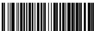
RS-232 BAUD RATE = 38400
RS-232 Baud Rate (continued)
Remember to cover any unused bar codes on this and the facing page to ensure that the scanner reads only the bar code you intend to scan.

RS-232 BAUD RATE = 57600

RS-232 BAUD RATE = 115200
RS-232 Number of Data Bits
Specifies number of data bits required for sending and receiving data.

NOTE
8 data bits with 2 stop bits and parity enabled is not a valid configuration.

NOTE
A setting of 7 data bits and no parity is invalid and will default to 8 data bits and no parity.
To set this feature:
- Scan the SWITCH bar code.
- Scan the bar code below representing the desired Data Bit setting. You'll need to cover any unused bar codes on this and the facing page to ensure that the scanner reads only the bar code you intend to scan.
- Complete the programming sequence by scanning the SWITCH bar code.


RS-232 Number of Stop Bits
Specifies number of stop bits required for sending and receiving data.

NOTE
8 data bits with 2 stop bits and parity enabled is not a valid configuration.
To set this feature:
- Scan the SWITCH bar code.
- Scan the bar code below representing the desired Stop Bit setting. You'll need to cover any unused bar codes on this and the facing page to ensure that the scanner reads only the bar code you intend to scan.
- Complete the programming sequence by scanning the SWITCH bar code.


RS-232 Parity

NOTE

NOTE
Specifies parity required for sending and receiving data.
8 data bits with 2 stop bits and parity enabled is not a valid configuration.
A setting of no parity and 7 data bits is invalid and will default to 8 data bits and no parity.
Options for this setting are:
• RS-232 PARITY = NONE on page 195
• RS-232 PARITY = EVEN on page 196
• RS-232 PARITY = ODD on page 196
To set this feature:
- Scan the SWITCH bar code.
- Scan the bar code below or on the following pages representing the desired Parity setting. You'll need to cover any unused bar codes, as well as facing pages to ensure that the scanner reads only the bar code you intend to scan.
- Complete the programming sequence by scanning the SWITCH bar code.

RS-232 PARITY = NONE
RS-232 Parity (continued)
Remember to cover any unused bar codes on this and the facing page to ensure that the scanner reads only the bar code you intend to scan.

RS-232 PARITY = EVEN

RS-232 PARITY = ODD
RS-232 Hardware Control
Enables/disables use of the RS-232 CTS signal for flow control and/or scan control.
Options are:
- Disable — The scanner transmits to the host regardless of any activity on the CTS line.
- Enable CTS Flow Control — The CTS signal controls transmission of data to the host.
- Enable CTS Scan Control — The CTS line must be active for scanner to read and transmit data. While the CTS line is inactive, scanner remains in a host–disabled state; following a successful label transmission, the CTS signal must transition to inactive and then to active to enable scanning for the next label.
- Enable Magellan SL CTS scan control — Emulates default Magellan SL setting for this feature.
To set this feature:
- Scan the SWITCH bar code.
- Scan bar code below or from the following page for the desired setting. You'll need to cover any unused bar codes on facing pages to ensure that the scanner reads only the bar code you intend to scan.
- Complete the programming sequence by scanning the SWITCH bar code.

RS-232 Hardware Control (continued)
Remember to cover any unused bar codes on this and the facing page to ensure that the scanner reads only the bar code you intend to scan.
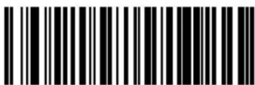
RS-232 HARDWARE CONTROL = ENABLE CTS FLOW CONTROL

RS-232 HARDWARE CONTROL = ENABLE CTS SCAN CONTROL
RS-232 Hardware Control (continued)
Remember to cover any unused bar codes on this and the facing page to ensure that the scanner reads only the bar code you intend to scan.
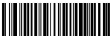
RS-232 HARDWARE CONTROL = ENABLE MGL SL CTS SCAN CONTROL
RS-232 Intercharacter Delay
Specifies delay between the end of one character and the beginning of the next in 10-millisecond increments.
To set the RS-232 Intercharacter Delay:
- Scan the SWITCH bar code.
- Scan the bar code below, SET RS-232 INTERCHARACTER DELAY on page 200. You'll need to cover any unused bar codes on this and the facing page to ensure that the scanner reads only the bar code you intend to scan.
- Scan the appropriate digits from the keypad in Appendix C that represent the desired delay. The selectable range is 0–100, which is the delay in 10–millisecond increments. Pad all single and double digit numbers with leading zeroes to yield a three-digit entry (000–100).
Examples: - The scanner will automatically exit Programming Mode when the appropriate amount of digits have been scanned.
$$ \begin{array}{l} 0 0 1 = 1 0 \mathrm{ms} \ 0 0 5 = 5 0 \mathrm{ms} \ 0 4 0 = 4 0 0 \mathrm{ms} \ 1 0 0 = 1, 0 0 0 \mathrm{ms} (1 \text { second }) \ \end{array} $$

SET RS-232 INTERCHARACTER DELAY
RS-232 Software Flow Control
Enables/disables RS-232 Flow Control using XON/ XOFF characters.

NOTE
This item will be ignored when the feature, RS-232 NAK Character on page 215, is enabled
To set this feature:
- Scan the SWITCH bar code.
- Scan either the enable or disable bar code below. You'll need to cover any unused bar codes on this and the facing page to ensure that the scanner reads only the bar code you intend to scan.
- Complete the programming sequence by scanning the SWITCH bar code.

RS-232 SOFTWARE FLOW CONTROL = DISABLE

RS-232 SOFTWARE FLOW CONTROL = ENABLE
RS-232 Host Echo
When enabled, this feature passes all data through the scanner to the host as it comes in. This feature is used for applications where "daisy chaining" of RS-232 devices onto the same cable is necessary. If, for example, one of the devices in the chain is a terminal where someone is entering data while another person is simultaneously scanning a bar code requiring transmission to the host, the scanner will wait for the RS-232 channel to be quiet for a specified period of time (set via RS-232 Host Echo Quiet Interval on page 203). The scanner can be set to observe this delay before sending its data in order to avoid RS-232 transmission conflicts.

NOTE
When RS-232 Host Echo is enabled, the following features are ignored: RS-232 Software Flow Control on page 201 and RS-232 ACK NAK Enable on page 212 as well as all other ACK/NAK related operations, plus processing of RS-232 host commands.
To enable/disable this feature:
- Scan the SWITCH bar code.
- Scan either the enable or disable bar code below. You'll need to cover any unused bar codes on this and the facing page to ensure that the scanner reads only the bar code you intend to scan.
- Complete the programming sequence by scanning the SWITCH bar code.
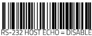

RS-232 Host Echo Quiet Interval
This setting specifies the time interval of RS-232 channel inactivity which must transpire before the scanner will break the host echo loop to transmit the bar code data that has just been scanned to the host.
- 0 - 100 = Time in 10-millisecond increments.
To set the Host Echo Quiet Interval:
- Scan the SWITCH bar code.
- Scan the bar code below, SET RS-232 HOST ECHO QUIET INTERVAL on page 203. You'll need to cover any unused bar codes on this and the facing page to ensure that the scanner reads only the bar code you intend to scan.
- Scan the appropriate digits from the keypad in Appendix C that represent the desired timeout. The selectable range is 0–100, which is the timeout in 10–millisecond increments. Pad all single and double digit numbers with leading zeroes to yield a three-digit entry (000–100).
Examples:
$$ \begin{array}{l} 0 0 1 = 1 0 \mathrm{ms} \ 0 0 5 = 5 0 \mathrm{ms} \ 0 4 0 = 4 0 0 \mathrm{ms} \ 1 0 0 = 1, 0 0 0 \mathrm{ms} (1 \text { second }) \ \end{array} $$
- The scanner will automatically exit Programming Mode when the appropriate amount of digits have been scanned.

SET RS-232 HOST ECHO QUIET INTERVAL
RS-232 Ignore Host Commands
When set to ignore host commands, the scanner will ignore all host commands except for the minimum set necessary to keep the interface active, transmit labels, and transmit scale information. For normal operation of the interface, disable this feature.
To set this feature:
- Scan the SWITCH bar code.
- Scan your selection from the bar codes below. You'll need to cover any unused bar codes on this and the facing page to ensure that the scanner reads only the bar code you intend to scan.
- Complete the programming sequence by scanning the SWITCH bar code.

RS-232 IGNORE HOST COMMANDS =
NORMAL (DO NOT IGNORE HOST COMMANDS)

RS-232 IGNORE HOST COMMANDS = ENABLE
RS-232 TTL
Specifies whether RS-232 interface provides TTL levels on the output pins TxD and RTS.
Choices are:
• Normal RS-232 levels
- TTL levels
To set this feature:
- Scan the SWITCH bar code.
- Scan the bar code below which represents the desired setting for this feature. You'll need to cover any unused bar codes on this and the facing page to ensure that the scanner reads only the bar code you intend to scan.
- Complete the programming sequence by scanning the SWITCH bar code.

RS-232 LEVELS = NORMAL RS-232

RS-232 LEVELS = TTL
RS-232 TTL Invert
Enables/disables inversion of TTL.
To set this feature:
- Scan the SWITCH bar code.
- Scan the bar code below which represents the desired setting for this feature. You'll need to cover any unused bar codes on this and the facing page to ensure that the scanner reads only the bar code you intend to scan.
- Complete the programming sequence by scanning the SWITCH bar code.

RS-232 TTL INVERT = NO INVERT

RS-232 TTL INVERT = INVERT
RS-232 ICL DC1 Character Delay Enable
Enables/disables the ability of the scanner to delay a DC1 response for 40 milliseconds.
To set this feature:
- Scan the SWITCH bar code.
- Scan the bar code below which represents the desired setting for this feature. You'll need to cover any unused bar codes on this and the facing page to ensure that the scanner reads only the bar code you intend to scan.
- Complete the programming sequence by scanning the SWITCH bar code.
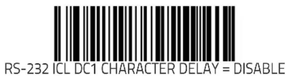

RS-232 Team POS ICL Scale
Enables/disables the ability of the scanner to enter TEAM POS ICL Scale mode.
To set this feature:
- Scan the SWITCH bar code.
- Scan the bar code below which represents the desired setting for this feature. You'll need to cover any unused bar codes on this and the facing page to ensure that the scanner reads only the bar code you intend to scan.
- Complete the programming sequence by scanning the SWITCH bar code.

RS-232 TEAM POS ICL SCALE MODE = DISABLE

RS-232 TEAM POS ICL SCALE MODE = ENABLE
RS-232 Beep on ASCII BEL
Enables/disables ability of scanner to beep (sound a good read tone) on receiving an ASCII BEL (07 hex).

To enable/disable this feature:
- Scan the SWITCH bar code.
- Scan either the enable or disable bar code below. You'll need to cover any unused bar codes on this and the facing page to ensure that the scanner reads only the bar code you intend to scan.
- Complete the programming sequence by scanning the SWITCH bar code.
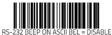

RS-232 Beep After Weigh
Enables/disables the ability of the scanner to beep after weight data is transmitted to the host. Scale interfaces that support this item are: RS-232 ICL, RS-232 SASI, and RS-232 Single Cable.
To enable/disable the Beep After Weigh feature:
- Scan the SWITCH bar code.
- Scan either the enable or disable bar code below. You'll need to cover any unused bar codes on this and the facing page to ensure that the scanner reads only the bar code you intend to scan.
- Complete the programming sequence by scanning the SWITCH bar code.

BEEP AFTER WEIGH = DISABLE

BEEP AFTER WEIGH = ENABLE
RS-232 Beep on Not on File
Select for the host to beep (or not) when a not-on-file condition is detected by the host. This feature is also applicable to single cable RS-232.

RS-232 BEEP ON NOT ON FILE = DISABLE

RS-232 BEEP ON NOT ON FILE = ENABLE
RS-232 ACK NAK Enable
This enables/disables the ability of the scanner to support the RS-232 ACK/NAK protocol. When configured, the scanner and/or host sends an "ACK" when it receives data properly, and sends "NAK" when the data is in error. Selections for this option are:
• D i s a b l e
- Label Transmission — the scanner expects an ACK/NAK response from the host when a label is sent)
- Host Acknowledgement — Enabled for Host Commands (the scanner will respond with ACK/NAK when the host sends a command)
- Label & Host — Enabled for both Label Transmission & Host Commands
To select the option for RS-232 ACK NAK Enable:
- Scan the SWITCH bar code.
- Scan the desired option from bar codes below and on the following page. You'll need to cover any unused bar codes on this and the facing page to ensure that the scanner reads only the bar code you intend to scan.
- Complete the programming sequence by scanning the SWITCH bar code.

RS-232 ACK NAK = DISABLE

RS-232 ACK/NAK = LABEL TRANSMISSION
RS-232 ACK NAK Enable (continued)
Remember to cover any unused bar codes on this and the facing page to ensure that the scanner reads only the bar code you intend to scan.

RS-232 ACK/NAK = HOST ACKNOWLEDGEMENT

RS-232 ACK/NAK = LABEL & HOST
RS-232 ACK Character

NOTE
This feature specifies which ASCII character will be used as an ACK character.
DO NOT set this feature to use previously defined characters such as XON, XOFF or host commands as this will conflict with normal operation of these characters. 8-bit data is not recognized when the feature, RS-232 Number of Data Bits on page 193, is set to 7 data bits.
To specify the RS-232 ACK Character:
- Scan the SWITCH bar code.
- Scan the bar code, SET RS-232 ACK CHARACTER on page 214 below. You'll need to cover any unused bar codes on this and the facing page to ensure the scanner reads only the bar code you intend to scan.
- Scan the appropriate digits from the keypad in Appendix C that represent the hex designation for the desired character. A table containing the ASCII Character Set on page 1 and their corresponding Hex Values is available in the inside back cover of this manual. ASCII parameters must be input by scanning a pair of hexadecimal digits for the desired character. For example, if ASCII "A" were the desired ACK character, you would scan the digits "4", then "1" (the ASCII corresponding hex value).
- The scanner will automatically exit Programming Mode when the appropriate amount of digits/characters have been scanned.

SET RS-232 ACK CHARACTER
RS-232 NAK Character

NOTE
This feature specifies which ASCII character will be used as a NAK character.
DO NOT set this feature to use previously defined characters such as XON, XOFF or host commands as this will conflict with normal operation of these characters. 8-bit data is not recognized when the feature, RS-232 Number of Data Bits on page 193, is set to 7 data bits.
To specify the RS-232 NAK Character:
- Scan the SWITCH bar code.
- Scan the bar code, SET RS-232 NAK CHARACTER on page 215 below. You'll need to cover any unused bar codes on this and the facing page to ensure the scanner reads only the bar code you intend to scan.
- Scan the appropriate digits from the keypad in Appendix C that represent the hex designation for the desired character. A table containing the ASCII Character Set on page 1 and their corresponding Hex Values is available in the inside back cover of this manual. ASCII parameters must be input by scanning a pair of hexadecimal digits for the desired character. For example, if ASCII "A" were the desired NAK character, you would scan the digits "4", then "1" (the ASCII corresponding hex value).
- The scanner will automatically exit Programming Mode when the appropriate amount of digits/characters have been scanned.

SET RS-232 NAK CHARACTER
RS-232 Retry on ACK NAK Timeout
This option specifies the action scanner performs on expiration of the RS-232 ACK NAK Timeout Value on page 217.
To set this feature:
- Scan the SWITCH bar code.
- Scan either the enable or disable bar code below. You'll need to cover any unused bar codes on this and the facing page to ensure that the scanner reads only the bar code you intend to scan.
- Complete the programming sequence by scanning the SWITCH bar code.

RS-232 RETRY ON ACK NAK TIMEOUT = DISABLE

RS-232 RETRY ON ACK NAK TIMEOUT = ENABLE
RS-232 ACK NAK Timeout Value
This item specifies the time the scanner will wait for an ACK character from the host following a label transmission.
• 0 = Infinite timeout
- 1 - 75 = Timeout in 200-millisecond increments
To set the ACK NAK Timeout Value:
- Scan the SWITCH bar code.
- Scan the bar code below, SET RS-232 ACK NAK TIMEOUT VALUE on page 217. You'll need to cover any unused bar codes on this and the facing page to ensure that the scanner reads only the bar code you intend to scan.
- Scan the appropriate digits from the keypad in Appendix C that represent the desired timeout. A setting of 0 specifies an infinite timeout. The remaining selectable range is 1–75, which is the timeout in 200-millisecond increments. Pad all single digit numbers with leading zeroes to yield a three-digit entry (000–075).
Examples:
$$ \begin{array}{l} 0 0 0 = \text { Infinite timeout } \ 0 0 1 = 2 0 0 \mathrm{ms} \ 0 0 5 = 1, 0 0 0 \mathrm{ms} (1 \text { second }) \ 0 4 0 = 8, 0 0 0 \mathrm{ms} (8 \text { seconds }) \ 0 7 5 = 1 5, 0 0 0 \mathrm{ms} (1 5 \text { seconds }) \ \end{array} $$
- The scanner will automatically exit Programming Mode when the appropriate amount of digits have been scanned.

SET RS-232 ACK NAK TIMEOUT VALUE
RS-232 ACK NAK Retry Count
This feature sets the number of times for the scanner to retry a label transmission under a retry condition.
To set the RS-232 ACK NAK Retry Count:
- Scan the SWITCH bar code.
- Scan the bar code, SET RS-232 ACK NAK RETRY COUNT on page 218 below. You'll need to cover any unused bar codes on this and the facing page to ensure that the scanner reads only the bar code you intend to scan.
- Scan the appropriate digits from the keypad in Appendix C that represent the desired number. The selectable range is 0–255 resets. Pad all single and double digit numbers with leading zeroes to yield a three-digit entry (000–255).

NOTE
A setting of 255 specifies "retry forever."
- The scanner will automatically exit Programming Mode when the appropriate amount of digits have been scanned.

SET RS-232 ACK NAK RETRY COUNT
RS-232 ACK NAK Error Handling
This item specifies the method the scanner will use to handle errors detected while waiting to receive the ACK character from the host. Errors include unrecognized host commands and communication errors such as parity or framing errors.
- Ignore Errors (recommended setting)
- Assume ACK (risk of lost label data)
- Assume NAK (risk of duplicate label)
To select the option for RS-232 ACK NAK Error Handling:
- Scan the SWITCH bar code.
- Scan the desired option from the bar codes below. You'll need to cover any unused bar codes on this and the facing page to ensure that the scanner reads only the bar code you intend to scan.
- Complete the programming sequence by scanning the SWITCH bar code.

RS-232 ACK NAK ERROR HANDLING = IGNORE ERRORS
RS-232 ACK NAK Error Handling (continued)
Remember to cover any unused bar codes on this and the facing page to ensure that the scanner reads only the bar code you intend to scan.

RS-232 ACK NAK ERROR HANDLING = ASSUME ACK

RS-232 ACK NAK ERROR HANDLING = ASSUME NAK
RS-232 Indicate Transmission Failure
Enables/disables an audible error indication upon a transmission failure.

RS-232 INDICATE TRANSMISSION FAILURE = DISABLE

RS-232 INDICATE TRANSMISSION FAILURE = ENABLE
Single Cable RS-232 Options
The RS-232 Single Cable interface shares some configuration options with other RS-232 interfaces. Rather than repeat them in this chapter as Single Cable options, please find them referenced as follows:
• "RS-232 Baud Rate" on page 189
- "RS-232 Number of Data Bits" on page 193
- "RS-232 Number of Stop Bits" on page 194
- "RS-232 Parity" on page 195
- "RS-232 Software Flow Control" on page 201
- "RS-232 Beep After Weigh" on page 210
- "RS-232 Beep on Not on File" on page 211
Single Cable RS-232 Scanner Only Protocol
This sets the type of interface protocol that will be used in Single Cable RS-232.
Options are:
- Scanner/scale RS-232 protocol
- Scanner only RS-232 protocol
To set this feature:
- Scan the SWITCH bar code.
- Scan the bar code below representing the desired option. You'll need to cover any unused bar codes on this and the facing page to ensure that the scanner reads only the bar code you intend to scan.
- Complete the programming sequence by scanning the SWITCH bar code.
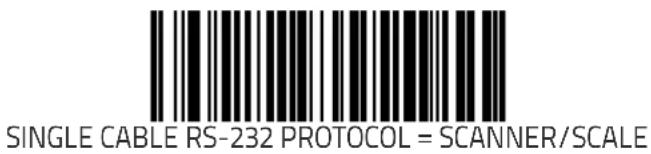

SINGLE CABLE RS-232 PROTOCOL = SCANNER ONLY
Single Cable RS-232 Stale Weight Timeout
Specifies the amount of time (in 10 msec increments) that scale data is presented to the host before being discarded.
To set the Timeout:
- Scan the SWITCH bar code.
- Scan your selection from the bar codes below. You'll need to cover any unused bar codes on this and the facing page to ensure that the scanner reads only the bar code you intend to scan.
- Complete the programming sequence by scanning the SWITCH bar code.


STALE WEIGHT TIMEOUT = 230 msec
Single Cable RS-232 Stale Weight Timeout (continued)
Remember to cover any unused bar codes on this and the facing page to ensure that the scanner reads only the bar code you intend to scan.
STALE WEIGHT TIMEOUT = 250 msec

STALE WEIGHT TIMEOUT = 330 msec
Single Cable RS-232 Scale — Transmit Weight Digits
Specifies whether the scale transmits weight data as five digits or as four digits.
To set this feature:
- Scan the SWITCH bar code.
- Scan the bar code below representing the desired option. You'll need to cover any unused bar codes on this and the facing page to ensure that the scanner reads only the bar code you intend to scan.
- Complete the programming sequence by scanning the SWITCH bar code.


TRANSMIT WEIGHT DIGITS = FOUR DIGITS
Single Cable Manufacturer Extensions
Enables/Disables manufacturer ^1 extensions to the Single Cable RS-232 interface. These extensions communicate scale calibration information to the host.
To set this feature:
- Scan the SWITCH bar code.
- Scan either the enable or disable bar code below. You'll need to cover any unused bar codes on this and the facing page to ensure that the scanner reads only the bar code you intend to scan.
- Complete the programming sequence by scanning the SWITCH bar code.


- The manufacturer of the scanner.
Single Cable Pacesetter Plus Enable
Enables/disables the scanner's ability to send Pacesetter Plus information as trailers to UPC/EAN label data.
To set this feature:
- Scan the SWITCH bar code.
- Scan either the enable or disable bar code below. You'll need to cover any unused bar codes on this and the facing page to ensure that the scanner reads only the bar code you intend to scan.
- Complete the programming sequence by scanning the SWITCH bar code.


SINGLE CABLE PACESETTER PLUS = ENABLE
Single Cable RS-232 RTS CTS Selection
Specifies how RTS and CTS are used to control the data flow. RTS is controlled by the Scanner and can be continuously held high/low, or can be asserted during label transmission. The scanner looks at CTS, as the configuration values state, to determine when to send label data.
Choices are:
- Option 0 = RTS is held in low state and CTS is ignored
- Option 1 = RTS is held in high state and CTS is ignored
- Option 2 = Assert RTS and wait for CTS to be asserted
- Option 3 = Assert RTS and ignore CTS
- Option 4 = RTS held low, wait for CTS to be asserted
- Option 5 = RTS held high, wait for CTS to be asserted
To set this feature:
- Scan the SWITCH bar code.
- Scan a bar code below or on the following pages representing the desired option. You'll need to cover any unused bar codes, as well as facing pages to ensure that the scanner reads only the bar code you intend to scan.
- Complete the programming sequence by scanning the SWITCH bar code.
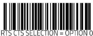

Single Cable RS-232 RTS CTS Selection (continued)
Remember to cover any unused bar codes on this and the facing page to ensure that the scanner reads only the bar code you intend to scan.

RTS CTS SELECTION = OPTION 2

RTS CTS SELECTION = OPTION 3
Single Cable RS-232 RTS CTS Selection (continued)
Remember to cover any unused bar codes on this and the facing page to ensure that the scanner reads only the bar code you intend to scan.

RTS CTS SELECTION = OPTION 4

RTS CTS SELECTION = OPTION 5
Single Cable RS-232 Use BCC
Enables/disables the ability of the scanner to use BCC.
To set this feature:
- Scan the SWITCH bar code.
- Scan either the enable or disable bar code below. You'll need to cover any unused bar codes on this and the facing page to ensure that the scanner reads only the bar code you intend to scan.
- Complete the programming sequence by scanning the SWITCH bar code.

SINGLE CABLE RS-232 USE BCC = DISABLE

SINGLE CABLE RS-232 USE BCC = ENABLE
Single Cable RS-232 Use ACK/NAK
Enables/disables the ability of the scanner to use ACK/NAK.
To set this feature:
- Scan the SWITCH bar code.
- Scan either the enable or disable bar code below. You'll need to cover any unused bar codes on this and the facing page to ensure that the scanner reads only the bar code you intend to scan.
- Complete the programming sequence by scanning the SWITCH bar code.


Single Cable RS-232 Use STX
Enables/disables the ability of the scanner to use STX.
To set this feature:
- Scan the SWITCH bar code.
- Scan either the enable or disable bar code below. You'll need to cover any unused bar codes on this and the facing page to ensure that the scanner reads only the bar code you intend to scan.
- Complete the programming sequence by scanning the SWITCH bar code.

SINGLE CABLE RS-232 USE STX = DISABLE

SINGLE CABLE RS-232 USE STX = ENABLE
Set Single Cable RS-232 STX Character
This feature selects the STX character.
To specify the STX Character:
- Scan the SWITCH bar code.
- Scan the bar code, SET SINGLE CABLE RS-232 STX CHARACTER on page 235 below. You'll need to cover any unused bar codes on this and the facing page to ensure the scanner reads only the bar code you intend to scan.
- Scan the appropriate characters/digits from the keypad in Appendix C that represent the decimal designation for the desired character. A table containing the ASCII Character Set on page 1 and their corresponding decimal values is available in the inside back cover of this manual. ASCII parameters must be input by scanning decimal digits for each character. Pad all numbers with leading zeroes to yield a three-digit entry (001–127). Thus, to set a single character value of A, bar codes containing the digits '0', '6' and '5' must be scanned. The selectable range for this option is any decimal value from 001 to 127.
- The scanner will automatically exit Programming Mode when the appropriate amount of digits have been scanned.

SET SINGLE CABLE RS-232 STX CHARACTER
Set Single Cable RS-232 ETX Character
Allows selection of the ETX character.
To specify the ETX Character:
- Scan the SWITCH bar code.
- Scan the bar code, SET SINGLE CABLE RS-232 ETX CHARACTER on page 236 below. You'll need to cover any unused bar codes on this and the facing page to ensure the scanner reads only the bar code you intend to scan.
- Scan the appropriate characters/digits from the keypad in Appendix C that represent the decimal designation for the desired character. A table containing the ASCII Character Set on page 1 and their corresponding decimal values is available in the inside back cover of this manual. ASCII parameters must be input by scanning decimal digits for each character. Pad all numbers with leading zeroes to yield a three-digit entry (001–127). Thus, to set a single character value of A, bar codes containing the digits '0', '6' and '5' must be scanned. The selectable range for this option is any decimal value from 001 to 127.
- The scanner will automatically exit Programming Mode when the appropriate amount of digits have been scanned.

SET SINGLE CABLE RS-232 ETX CHARACTER
Keyboard Wedge/USB Keyboard Features
Features listed in this section apply to both the Keyboard Wedge and USB Keyboard interfaces unless otherwise noted.
Keyboard Interface — Keyboard Layout
This feature specifies the country/language to be supported by the keyboard.
To set this feature:
- Scan the SWITCH bar code.
- Scan the appropriate country bar code from the following pages. You'll need to cover any unused bar codes on that and the facing page to ensure that the scanner reads only the bar code you intend to scan.
- Complete the programming sequence by scanning the SWITCH bar code.

KEYBOARD LAYOUT = USA

KEYBOARD LAYOUT = BELGIUM
Keyboard Interface — Keyboard Layout (continued)
Remember to cover any unused bar codes on this and the facing page to ensure that the scanner reads only the bar code you intend to scan.

KEYBOARD LAYOUT = BRITAIN

KEYBOARD LAYOUT = DENMARK
Keyboard Interface — Keyboard Layout (continued)
Remember to cover any unused bar codes on this and the facing page to ensure that the scanner reads only the bar code you intend to scan.

KEYBOARD LAYOUT = FRANCE
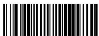
KEYBOARD LAYOUT = GERMANY
Keyboard Interface — Keyboard Layout (continued)
Remember to cover any unused bar codes on this and the facing page to ensure that the scanner reads only the bar code you intend to scan.

KEYBOARD LAYOUT = ITALY

KEYBOARD LAYOUT = NORWAY
Keyboard Interface — Keyboard Layout (continued)
Remember to cover any unused bar codes on this and the facing page to ensure that the scanner reads only the bar code you intend to scan.


KEYBOARD LAYOUT = SPAIN
Keyboard Interface — Keyboard Layout (continued)
Remember to cover any unused bar codes on this and the facing page to ensure that the scanner reads only the bar code you intend to scan.

KEYBOARD LAYOUT = SWEDEN

KEYBOARD LAYOUT = SWITZERLAND
Keyboard Interface — Keyboard Layout (continued)
Remember to cover any unused bar codes on this and the facing page to ensure that the scanner reads only the bar code you intend to scan.

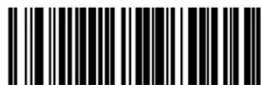
KEYBOARD LAYOUT = HUNGARY
Keyboard Interface — Keyboard Layout (continued)
Remember to cover any unused bar codes on this and the facing page to ensure that the scanner reads only the bar code you intend to scan.
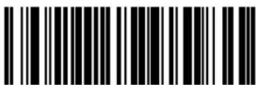
KEYBOARD LAYOUT = CZECH

KEYBOARD LAYOUT = SLOVAKIA
Keyboard Interface — Keyboard Layout (continued)
Remember to cover any unused bar codes on this and the facing page to ensure that the scanner reads only the bar code you intend to scan.

KEYBOARD LAYOUT = ROMANIA

KEYBOARD LAYOUT = CROATIA
Keyboard Interface — Keyboard Layout (continued)
Remember to cover any unused bar codes on this and the facing page to ensure that the scanner reads only the bar code you intend to scan.

Keyboard Interface Quiet Interval
Specifies amount of time to look for keyboard activity before scanner breaks keyboard connection in order to transmit data to host.
To set the Keyboard Interface Quiet Interval:
- Scan the SWITCH bar code.
- Scan the bar code below, SET KEYBOARD INTERFACE QUIET INTERVAL on page 246. You'll need to cover any unused bar codes on this and the facing page to ensure that the scanner reads only the bar code you intend to scan.
- Scan the appropriate digits from the keypad in Appendix C that represent the desired delay. The selectable range is 1–100, which is the interval duration in 10-millisecond increments. Pad all single and double digit numbers with leading zeroes to yield a three-digit entry (001–100).
Examples:
$$ \begin{array}{l} 0 0 1 = 1 0 \mathrm{ms} \ 0 0 5 = 5 0 \mathrm{ms} \ 0 4 0 = 4 0 0 \mathrm{ms} \ 1 0 0 = 1, 0 0 0 \mathrm{ms} (1 \text { second }) \ \end{array} $$
- The scanner will automatically exit Programming Mode when the appropriate amount of digits have been scanned.
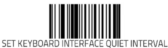
Keyboard Interface Caps Lock State
Specifies the format in which the scanner sends character data..
Choices are:
- CAPS LOCK OFF — send character data in normal format.
- CAPS LOCK ON — send character data in reverse case.
- SHIFT LOCK ON — send character data in shifted case. This option only applies to Wedge G. For other interface this setting results in a CAPS LOCK OFF functionality.
- CAPS LOCK COMPENSATION MODE — This only applies to the USB Keyboard Interface. For other interfaces, this setting results in a CAPS LOCK OFF functionality.
To set this feature:
- Scan the SWITCH bar code.
- Scan either the enable or disable bar code below. You'll need to cover any unused bar codes on this and the facing page to ensure that the scanner reads only the bar code you intend to scan.
- Complete the programming sequence by scanning the SWITCH bar code.

CAPS LOCK STATE = OFF

CAPS LOCK STATE = CAPS LOCK ON
Keyboard Interface Caps Lock State (continued)
Remember to cover any unused bar codes on this and the facing page to ensure that the scanner reads only the bar code you intend to scan.


CAPS LOCK STATE = CAPS LOCK COMPENSATION MODE
Keyboard Interface — Keyboard Simulation
Enables/disables ability of scanner to perform host communications normally performed by attached keyboard.

NOTE
This feature does not apply to the USB Keyboard interface.
All PCs check the keyboard status during the power-on Selftest. It is recommended that you enable this function if you are working without a keyboard installation. It simulates keyboard timing and passes the keyboard status to the PC during power-on.
To set this feature:
- Scan the SWITCH bar code.
- Scan either the enable or disable bar code below. You'll need to cover any unused bar codes on this and the facing page to ensure that the scanner reads only the bar code you intend to scan.
- Complete the programming sequence by scanning the SWITCH bar code.


Keyboard Interface — Control Characters
Specifies how the scanner transmits ASCII control characters to the host.

NOTE
This feature does not apply to the USB Keyboard interface.
Choices are:
- Disable Control Characters
- Enable transmission of control characters to host
- Send characters between 00H and 1FH according to a special function-key mapping table. (This is used to send keys that are not in the normal ASCII set; a unique set is provided for each available scancode set. Reference Appendix E, Keyboard Function Key Mappings.)
To set this feature:
- Scan the SWITCH bar code.
- Scan your choice from the Control Characters feature bar codes below. You'll need to cover any unused bar codes on this and the facing page to ensure that the scanner reads only the bar code you intend to scan.
- Complete the programming sequence by scanning the SWITCH bar code.

CONTROL CHARACTERS = DISABLE
Keyboard Interface — Control Characters (continued)
Remember to cover any unused bar codes on this and the facing page to ensure that the scanner reads only the bar code you intend to scan.

CONTROL CHARACTERS = ENABLE TRANSMISSION OF CTL CHARACTERS

CONTROL CHARACTERS = ENABLE FUNCTION KEY MAPPING
Keyboard Interface — Intercharacter Delay
Sets the delay between the end of one character and the beginning of the next, in 10 millisecond increments.
To specify the intercharacter delay:
- Scan the SWITCH bar code.
- Scan the bar code below, SET KEYBOARD WEDGE INTERCHARACTER DELAY on page 252. You'll need to cover any unused bar codes on this and the facing page to ensure that the scanner reads only the bar code you intend to scan.
- Scan the appropriate digits from the keypad in Appendix C that represent the desired delay. The selectable range is 0–100, which is the delay in 10–millisecond increments. Pad all single and double digit numbers with leading zeroes to yield a three-digit entry (000–100).
Examples: - The scanner will automatically exit Programming Mode when the appropriate amount of digits have been scanned.
$$ \begin{array}{l} 0 0 1 = 1 0 \mathrm{ms} \ 0 0 5 = 5 0 \mathrm{ms} \ 0 4 0 = 4 0 0 \mathrm{ms} \ 1 0 0 = 1, 0 0 0 \mathrm{ms} (1 \text { second }) \ \end{array} $$

SET KEYBOARD WEDGE INTERCHARACTER DELAY
Symbology Programming
NOTE
If the scanner's interface type must be changed, always be sure that interface configuration is the FIRST item scanned during a programming session. (Selecting an interface type resets ALL other configuration items — including symbology programming — to the factory default for that interface type.)
Coupon Control
Used to control the method of processing coupon labels.
Options are:
- Disable coupon decoding
- Enable UPC/EAN coupon decoding
- Enable RSS coupon decoding
To set this feature:
- Scan the SWITCH bar code.
- Scan either the enable or disable bar code below. You'll need to cover any unused bar codes on this and the facing page to ensure that the scanner reads only the bar code you intend to scan.
- Complete the programming sequence by scanning the SWITCH bar code.
Coupon Control (continued)
Remember to cover any unused bar codes on this and the facing page to ensure that the scanner reads only the bar code you intend to scan.

COUPON CONTROL = ENABLE UPC/EAN COUPON DECODING
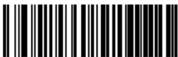
COUPON CONTROL = ENABLE DATABASE COUPON DECODING
UPC-A Enable
Enables/disables the ability of the scanner to decode UPC-A labels. To set this feature:
- Scan the SWITCH bar code.
- Scan either the enable or disable bar code below. You'll need to cover any unused bar codes on this and the facing page to ensure that the scanner reads only the bar code you intend to scan.
- Complete the programming sequence by scanning the SWITCH bar code.
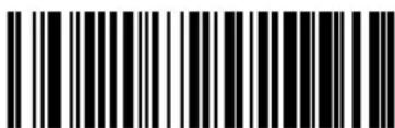
UPC-A = DISABLE

UPC-A = ENABLE
UPC-A Number System Character Transmission
Enables/disables transmission of a UPC-A number system character.

NOTE
This feature MUST be enabled for IBM interfaces for proper function.
To set this feature:
- Scan the SWITCH bar code.
- Scan either the enable or disable bar code below. You'll need to cover any unused bar codes on this and the facing page to ensure that the scanner reads only the bar code you intend to scan.
- Complete the programming sequence by scanning the SWITCH bar code.

UPC-A NUMBER SYSTEM CHARACTER TRANSMISSION = DISABLE

UPC-A NUMBER SYSTEM CHARACTER TRANSMISSION = ENABLE
UPC-A Check Character Transmission
Enables/disables transmission of a UPC-A check character.
To set this feature:
- Scan the SWITCH bar code.
- Scan either the enable or disable bar code below. You'll need to cover any unused bar codes on this and the facing page to ensure that the scanner reads only the bar code you intend to scan.
- Complete the programming sequence by scanning the SWITCH bar code.


UPC-A CHECK CHARACTER TRANSMISSION = ENABLE
Expand UPC-A to EAN-13
Enables/disables expansion of UPC-A labels to EAN/JAN-13.
To set this feature:
- Scan the SWITCH bar code.
- Scan either the enable or disable bar code below. You'll need to cover any unused bar codes on this and the facing page to ensure that the scanner reads only the bar code you intend to scan.
- Complete the programming sequence by scanning the SWITCH bar code.

EXPAND UPC-A TO EAN/JAN-13 = DISABLE
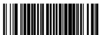
EXPAND UPC-A TO EAN/JAN-13 = ENABLE
UPC-A Label ID

NOTE
This feature specifies a UPC-A label ID to be added to bar code data.
The programming feature, Label ID Control, designates whether the Label ID is transmitted as a prefix or suffix or if Label ID is disabled.
To set this feature:
- Scan the SWITCH bar code.
- Scan the bar code, SET UPC-A LABEL ID on page 259 below. You'll need to cover any unused bar codes on this and the facing page to ensure the scanner reads only the bar code you intend to scan.
-
Scan the appropriate digits from the keypad in Appendix C that represent the desired Label ID characters; entered as two hex pairs. A table containing the ASCII Character Set on page 1 and their corresponding Hex Values is available in the inside back cover of this manual. ASCII parameters must be input by scanning a pair of hexadecimal digits for each character. Thus, to set a two-character value of AB, bar codes containing the digits '4', '1', '4', and '2' must be scanned. The selectable range for this option is any hex value from 00 to FF.
-
Complete the programming sequence by scanning the SWITCH bar code.

SET UPC-A LABEL ID
UPC-A 2-Digit Supplemental Label ID
This feature specifies a UPC-A 2-Digit Supplemental label ID to be added to bar code data.

NOTE
The programming feature, Label ID Control, designates whether the Label ID is transmitted as a prefix or suffix or if Label ID is disabled.
To set this feature:
- Scan the SWITCH bar code.
- Scan the bar code, SET UPC-A 2-DIGIT SUPPLEMENTAL LABEL ID on page 260 below. You'll need to cover any unused bar codes on this and the facing page to ensure the scanner reads only the bar code you intend to scan.
-
Scan the appropriate digits from the keypad in Appendix C that represent the desired Label ID characters; entered as two hex pairs. A table containing the ASCII Character Set on page 1 and their corresponding Hex Values is available in the inside back cover of this manual. ASCII parameters must be input by scanning a pair of hexadecimal digits for each character. Thus, to set a two-character value of AB, bar codes containing the digits '4', '1', '4', and '2' must be scanned. The selectable range for this option is any hex value from 00 to FF.
-
Complete the programming sequence by scanning the SWITCH bar code.

SET UPC-A 2-DIGIT SUPPLEMENTAL LABEL ID
UPC-A 5-Digit Supplemental Label ID
This feature specifies a UPC-A 5-Digit Supplemental label ID to be added to bar code data.

NOTE
The programming feature, Label ID Control, designates whether the Label ID is transmitted as a prefix or suffix or if Label ID is disabled.
To set this feature:
- Scan the SWITCH bar code.
- Scan the bar code, SET UPC-A 5-DIGIT SUPPLEMENTAL LABEL ID on page 261 below. You'll need to cover any unused bar codes on this and the facing page to ensure the scanner reads only the bar code you intend to scan.
-
Scan the appropriate digits from the keypad in Appendix C that represent the desired Label ID characters; entered as two hex pairs. A table containing the ASCII Character Set on page 1 and their corresponding Hex Values is available in the inside back cover of this manual. ASCII parameters must be input by scanning a pair of hexadecimal digits for each character. Thus, to set a two-character value of AB, bar codes containing the digits '4', '1', '4', and '2' must be scanned. The selectable range for this option is any hex value from 00 to FF.
-
Complete the programming sequence by scanning the SWITCH bar code.

SET UPC-A 5-DIGIT SUPPLEMENTAL LABEL ID
UPC-A 128 Supplemental Label ID
This feature specifies a UPC-A 128 Supplemental label ID to be added to bar code data.

NOTE
The programming feature, Label ID Control, designates whether the Label ID is transmitted as a prefix or suffix or if Label ID is disabled.
To set this feature:
- Scan the SWITCH bar code.
- Scan the bar code, SET UPC-A 128 SUPPLEMENTAL LABEL ID on page 262 below. You'll need to cover any unused bar codes on this and the facing page to ensure the scanner reads only the bar code you intend to scan.
-
Scan the appropriate digits from the keypad in Appendix C that represent the desired Label ID characters; entered as two hex pairs. A table containing the ASCII Character Set on page 1 and their corresponding Hex Values is available in the inside back cover of this manual. ASCII parameters must be input by scanning a pair of hexadecimal digits for each character. Thus, to set a two-character value of AB, bar codes containing the digits '4', '1', '4', and '2' must be scanned. The selectable range for this option is any hex value from 00 to FF.
-
Complete the programming sequence by scanning the SWITCH bar code.

SET UPC-A 128 SUPPLEMENTAL LABEL ID
UPC-A Minimum Reads
Specifies the minimum number of consecutive times a UPC-A label must be decoded before it is accepted as a good read.
To set this feature:
- Scan the SWITCH bar code.
- Scan the bar code representing the desired option below or on the following pages. You'll need to cover any unused bar codes on facing pages to ensure that the scanner reads only the bar code you intend to scan.
Complete the programming sequence by scanning the SWITCH bar code.

UPC-A MINIMUM READS = 1

UPC-A MINIMUM READS = 2
UPC-A Minimum Reads (continued)
Remember to cover any unused bar codes on this and the facing page to ensure that the scanner reads only the bar code you intend to scan.


UPC-E Enable
Enables/disables the ability of the scanner to decode UPC-E labels. To set this feature:
- Scan the SWITCH bar code.
- Scan either the enable or disable bar code below. You'll need to cover any unused bar codes on this and the facing page to ensure that the scanner reads only the bar code you intend to scan.
- Complete the programming sequence by scanning the SWITCH bar code.
UPC-E = DISABLE

UPC-E = ENABLE
UPC-E Number System Character Transmission
Enables/disables transmission of a UPC-E number system character. To set this feature:
- Scan the SWITCH bar code.
- Scan either the enable or disable bar code below. You'll need to cover any unused bar codes on this and the facing page to ensure that the scanner reads only the bar code you intend to scan.
- Complete the programming sequence by scanning the SWITCH bar code.

UPC-E NUMBER SYSTEM CHARACTER TRANSMISSION = DISABLE
UPC-E NUMBER SYSTEM CHARACTER TRANSMISSION = ENABLE
UPC-E Check Character Transmission
Enables/disables transmission of a UPC-E check character.
To set this feature:
- Scan the SWITCH bar code.
- Scan either the enable or disable bar code below. You'll need to cover any unused bar codes on this and the facing page to ensure that the scanner reads only the bar code you intend to scan.
- Complete the programming sequence by scanning the SWITCH bar code.

UPC-E CHECK CHARACTER TRANSMISSION = DISABLE

UPC-E CHECK CHARACTER TRANSMISSION = ENABLE
Expand UPC-E to UPC-A
Enables/disables expansion of UPC-E labels to UPC-A.
To set this feature:
- Scan the SWITCH bar code.
- Scan either the enable or disable bar code below. You'll need to cover any unused bar codes on this and the facing page to ensure that the scanner reads only the bar code you intend to scan.
- Complete the programming sequence by scanning the SWITCH bar code.


Expand UPC-E to EAN-13
Enables/disables expansion of UPC-E labels to EAN/JAN-13.
To set this feature:
- Scan the SWITCH bar code.
- Scan either the enable or disable bar code below. You'll need to cover any unused bar codes on this and the facing page to ensure that the scanner reads only the bar code you intend to scan.
- Complete the programming sequence by scanning the SWITCH bar code.

EXPAND UPC-E TO EAN/JAN-13 = DISABLE

EXPAND UPC-E TO EAN/JAN-13 = ENABLE
UPC-E Label ID

NOTE
This feature specifies a UPC-E label ID to be added to bar code data.
The programming feature, Label ID Control, designates whether the Label ID is transmitted as a prefix or suffix or if Label ID is disabled.
To set this feature:
- Scan the SWITCH bar code.
- Scan the bar code, SET UPC-E LABEL ID on page 270 below. You'll need to cover any unused bar codes on this and the facing page to ensure the scanner reads only the bar code you intend to scan.
- Scan the appropriate digits from the keypad in Appendix C that represent the desired Label ID characters; entered as two hex pairs. A table containing the ASCII Character Set on page 1 and their corresponding Hex Values is available in the inside back cover of this manual. ASCII parameters must be input by scanning a pair of hexadecimal digits for each character. Thus, to set a two-character value of AB, bar codes containing the digits '4', '1', '4', and '2' must be scanned. The selectable range for this option is any hex value from 00 to FF.
- Complete the programming sequence by scanning the SWITCH bar code.

SET UPC-E LABEL ID
UPC-E 2-Digit Supplemental Label ID
This feature specifies a UPC-E 2-Digit Supplemental label ID to be added to bar code data.

NOTE
The programming feature, Label ID Control, designates whether the Label ID is transmitted as a prefix or suffix or if Label ID is disabled.
To set this feature:
- Scan the SWITCH bar code.
- Scan the bar code, SET UPC-E 2-DIGIT SUPPLEMENTAL LABEL ID on page 271 below. You'll need to cover any unused bar codes on this and the facing page to ensure the scanner reads only the bar code you intend to scan.
-
Scan the appropriate digits from the keypad in Appendix C that represent the desired Label ID characters; entered as two hex pairs. A table containing the ASCII Character Set on page 1 and their corresponding Hex Values is available in the inside back cover of this manual. ASCII parameters must be input by scanning a pair of hexadecimal digits for each character. Thus, to set a two-character value of AB, bar codes containing the digits '4', '1', '4', and '2' must be scanned. The selectable range for this option is any hex value from 00 to FF.
-
Complete the programming sequence by scanning the SWITCH bar code.

SET UPC-E 2-DIGIT SUPPLEMENTAL LABEL ID
UPC-E 5-Digit Supplemental Label ID
This feature specifies a UPC-E 5-Digit Supplemental label ID to be added to bar code data.

NOTE
The programming feature, Label ID Control, designates whether the Label ID is transmitted as a prefix or suffix or if Label ID is disabled.
To set this feature:
- Scan the SWITCH bar code.
- Scan the bar code, SET UPC-E 5-DIGIT SUPPLEMENTAL LABEL ID on page 272 below. You'll need to cover any unused bar codes on this and the facing page to ensure the scanner reads only the bar code you intend to scan.
-
Scan the appropriate digits from the keypad in Appendix C that represent the desired Label ID characters; entered as two hex pairs. A table containing the ASCII Character Set on page 1 and their corresponding Hex Values is available in the inside back cover of this manual. ASCII parameters must be input by scanning a pair of hexadecimal digits for each character. Thus, to set a two-character value of AB, bar codes containing the digits '4', '1', '4', and '2' must be scanned. The selectable range for this option is any hex value from 00 to FF.
-
Complete the programming sequence by scanning the SWITCH bar code.

SET UPC-E 5-DIGIT SUPPLEMENTAL LABEL ID
UPC-E 128 Supplemental Label ID
This feature specifies a UPC-E 128 Supplemental label ID to be added to bar code data.

NOTE
The programming feature, Label ID Control, designates whether the Label ID is transmitted as a prefix or suffix or if Label ID is disabled.
To set this feature:
- Scan the SWITCH bar code.
- Scan the bar code, SET UPC-E 128 SUPPLEMENTAL LABEL ID on page 273 below. You'll need to cover any unused bar codes on this and the facing page to ensure the scanner reads only the bar code you intend to scan.
-
Scan the appropriate digits from the keypad in Appendix C that represent the desired Label ID characters; entered as two hex pairs. A table containing the ASCII Character Set on page 1 and their corresponding Hex Values is available in the inside back cover of this manual. ASCII parameters must be input by scanning a pair of hexadecimal digits for each character. Thus, to set a two-character value of AB, bar codes containing the digits '4', '1', '4', and '2' must be scanned. The selectable range for this option is any hex value from 00 to FF.
-
Complete the programming sequence by scanning the SWITCH bar code.

SET UPC-E 128 SUPPLEMENTAL LABEL ID
UPC-E Minimum Reads
Specifies the minimum number of consecutive times a UPC-E label must be decoded before it is accepted as a good read.
To set this feature:
- Scan the SWITCH bar code.
- Scan the bar code representing the desired option below or on the following pages. You'll need to cover any unused bar codes on facing pages to ensure that the scanner reads only the bar code you intend to scan.
Complete the programming sequence by scanning the SWITCH bar code.

UPC-E MINIMUM READS = 1

UPC-E MINIMUM READS = 2
UPC-E Minimum Reads (continued)
Remember to cover any unused bar codes on this and the facing page to ensure that the scanner reads only the bar code you intend to scan.


EAN-13 Enable
Enables/disables the ability of the scanner to decode EAN/JAN-13 labels.
To set this feature:
- Scan the SWITCH bar code.
- Scan either the enable or disable bar code below. You'll need to cover any unused bar codes on this and the facing page to ensure that the scanner reads only the bar code you intend to scan.
- Complete the programming sequence by scanning the SWITCH bar code.

EAN-13 = DISABLE
EAN-13 = ENABLE
EAN-13 First Character Transmission
Enables/disables transmission of EAN/JAN-13 first character.
To set this feature:
- Scan the SWITCH bar code.
- Scan either the enable or disable bar code below. You'll need to cover any unused bar codes on this and the facing page to ensure that the scanner reads only the bar code you intend to scan.
- Complete the programming sequence by scanning the SWITCH bar code.

EAN-13 FIRST CHARACTER TRANSMISSION = DISABLE

EAN-13 FIRST CHARACTER TRANSMISSION = ENABLE
EAN-13 Check Character Transmission
Enables/disables transmission of an EAN/JAN-13 check character. To set this feature:
- Scan the SWITCH bar code.
- Scan either the enable or disable bar code below. You'll need to cover any unused bar codes on this and the facing page to ensure that the scanner reads only the bar code you intend to scan.
- Complete the programming sequence by scanning the SWITCH bar code.

EAN-13 CHECK CHARACTER TRANSMISSION = DISABLE

EAN-13 CHECK CHARACTER TRANSMISSION = ENABLE
EAN-13 ISBN Conversion Enable
Enables/disables conversion of EAN/JAN-13 labels starting with 978 to Bookland ISBN labels.

NOTE
If any add-on information is present on the label prior to the conversion to ISBN, the add-on data will be discarded. Only the base label will be converted.
To set this feature:
- Scan the SWITCH bar code.
- Scan either the enable or disable bar code below. You'll need to cover any unused bar codes on this and the facing page to ensure that the scanner reads only the bar code you intend to scan.
- Complete the programming sequence by scanning the SWITCH bar code.


EAN 13 Label ID
This feature specifies an EAN 13 label ID to be added to bar code data.
To set this feature:

The programming feature, Label ID Control, designates whether the Label ID is transmitted as a prefix or suffix or if Label ID is disabled.
To set this feature:
- Scan the SWITCH bar code.
- Scan the bar code, SET EAN 13 LABEL ID on page 280 below. You'll need to cover any unused bar codes on this and the facing page to ensure the scanner reads only the bar code you intend to scan.
-
Scan the appropriate digits from the keypad in Appendix C that represent the desired Label ID characters; entered as two hex pairs. A table containing the ASCII Character Set on page 1 and their corresponding Hex Values is available in the inside back cover of this manual. ASCII parameters must be input by scanning a pair of hexadecimal digits for each character. Thus, to set a two-character value of AB, bar codes containing the digits '4', '1', '4', and '2' must be scanned. The selectable range for this option is any hex value from 00 to FF.
-
Complete the programming sequence by scanning the SWITCH bar code.

SET EAN 13 LABEL ID
EAN-13 2-Digit Supplemental Label ID
This feature specifies an EAN-13 2-Digit Supplemental label ID to be added to bar code data.

NOTE
The programming feature, Label ID Control, designates whether the Label ID is transmitted as a prefix or suffix or if Label ID is disabled.
To set this feature:
- Scan the SWITCH bar code.
- Scan the bar code, SET EAN-13 2-DIGIT SUPPLEMENTAL LABEL ID on page 281 below. You'll need to cover any unused bar codes on this and the facing page to ensure the scanner reads only the bar code you intend to scan.
-
Scan the appropriate digits from the keypad in Appendix C that represent the desired Label ID characters; entered as two hex pairs. A table containing the ASCII Character Set on page 1 and their corresponding Hex Values is available in the inside back cover of this manual. ASCII parameters must be input by scanning a pair of hexadecimal digits for each character. Thus, to set a two-character value of AB, bar codes containing the digits '4', '1', '4', and '2' must be scanned. The selectable range for this option is any hex value from 00 to FF.
-
Complete the programming sequence by scanning the SWITCH bar code.

SET EAN-13 2-DIGIT SUPPLEMENTAL LABEL ID
EAN-13 5-Digit Supplemental Label ID
This feature specifies an EAN-13 5-Digit Supplemental label ID to be added to bar code data.

The programming feature, Label ID Control, designates whether the Label ID is transmitted as a prefix or suffix or if Label ID is disabled.
NOTE
To set this feature:
- Scan the SWITCH bar code.
- Scan the bar code, SET EAN-13 5-DIGIT SUPPLEMENTAL LABEL ID on page 282 below. You'll need to cover any unused bar codes on this and the facing page to ensure the scanner reads only the bar code you intend to scan.
-
Scan the appropriate digits from the keypad in Appendix C that represent the desired Label ID characters; entered as two hex pairs. A table containing the ASCII Character Set on page 1 and their corresponding Hex Values is available in the inside back cover of this manual. ASCII parameters must be input by scanning a pair of hexadecimal digits for each character. Thus, to set a two-character value of AB, bar codes containing the digits '4', '1', '4', and '2' must be scanned. The selectable range for this option is any hex value from 00 to FF.
-
Complete the programming sequence by scanning the SWITCH bar code.
SET EAN-13 5-DIGIT SUPPLEMENTAL LABEL ID
EAN-13 128 Supplemental Label ID
This feature specifies an EAN-13 128 Supplemental label ID to be added to bar code data.

NOTE
The programming feature, Label ID Control, designates whether the Label ID is transmitted as a prefix or suffix or if Label ID is disabled.
To set this feature:
- Scan the SWITCH bar code.
- Scan the bar code, SET EAN-13 128 SUPPLEMENTAL LABEL ID = DISABLE on page 283 below. You'll need to cover any unused bar codes on this and the facing page to ensure the scanner reads only the bar code you intend to scan.
-
Scan the appropriate digits from the keypad in Appendix C that represent the desired Label ID characters; entered as two hex pairs. A table containing the ASCII Character Set on page 1 and their corresponding Hex Values is available in the inside back cover of this manual. ASCII parameters must be input by scanning a pair of hexadecimal digits for each character. Thus, to set a two-character value of AB, bar codes containing the digits '4', '1', '4', and '2' must be scanned. The selectable range for this option is any hex value from 00 to FF.
-
Complete the programming sequence by scanning the SWITCH bar code.

SET EAN-13 128 SUPPLEMENTAL LABEL ID = DISABLE
EAN-13 Minimum Reads
Specifies the minimum number of consecutive times an EAN-13 label must be decoded before it is accepted as a good read.
To set this feature:
- Scan the SWITCH bar code.
- Scan the bar code representing the desired option below or on the following pages. You'll need to cover any unused bar codes on facing pages to ensure that the scanner reads only the bar code you intend to scan.
Complete the programming sequence by scanning the SWITCH bar code.
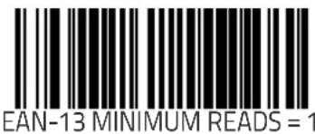

EAN-13 Minimum Reads (continued)
Remember to cover any unused bar codes on this and the facing page to ensure that the scanner reads only the bar code you intend to scan.

EAN-13 MINIMUM READS = 3

EAN-13 MINIMUM READS = 4
Bookland Label ID

NOTE
This feature specifies a Bookland label ID to be added to bar code data.
The programming feature, Label ID Control, designates whether the Label ID is transmitted as a prefix or suffix or if Label ID is disabled.
To set this feature:
- Scan the SWITCH bar code.
- Scan the bar code, SET BOOKLAND LABEL ID on page 286 below. You'll need to cover any unused bar codes on this and the facing page to ensure the scanner reads only the bar code you intend to scan.
-
Scan the appropriate digits from the keypad in Appendix C that represent the desired Label ID characters; entered as two hex pairs. A table containing the ASCII Character Set on page 1 and their corresponding Hex Values is available in the inside back cover of this manual. ASCII parameters must be input by scanning a pair of hexadecimal digits for each character. Thus, to set a two-character value of AB, bar codes containing the digits '4', '1', '4', and '2' must be scanned. The selectable range for this option is any hex value from 00 to FF.
-
Complete the programming sequence by scanning the SWITCH bar code.
SET BOOKLAND LABEL ID
EAN-8 Enable
Enables/disables the ability of the scanner to decode EAN/JAN-8 labels.
To set this feature:
- Scan the SWITCH bar code.
- Scan either the enable or disable bar code below. You'll need to cover any unused bar codes on this and the facing page to ensure that the scanner reads only the bar code you intend to scan.
- Complete the programming sequence by scanning the SWITCH bar code.

EAN-8 = DISABLE

EAN-8 = ENABLE
EAN-8 Check Character Transmission
Enables/disables transmission of an EAN/JAN-8 check character. To set this feature:
- Scan the SWITCH bar code.
- Scan either the enable or disable bar code below. You'll need to cover any unused bar codes on this and the facing page to ensure that the scanner reads only the bar code you intend to scan.
- Complete the programming sequence by scanning the SWITCH bar code.

EAN-8 CHECK CHARACTER TRANSMISSION = DISABLE

EAN-8 CHECK CHARACTER TRANSMISSION = ENABLE
Expand EAN-8 to EAN-13
Enables/disables expansion of EAN/JAN-8 labels to EAN/JAN-13. To set this feature:
- Scan the SWITCH bar code.
- Scan either the enable or disable bar code below. You'll need to cover any unused bar codes on this and the facing page to ensure that the scanner reads only the bar code you intend to scan.
- Complete the programming sequence by scanning the SWITCH bar code.


EXPAND EAN/JAN-8 TO EAN/JAN-13 = ENABLE
EAN-8/JAN-8 Guard Insertion
Enables/Disables the ability of the scanner to insert a guard pattern into an otherwise complete EAN-8 segment it has received.
To set this feature:
- Scan the SWITCH bar code.
- Scan either the enable or disable bar code below. You'll need to cover any unused bar codes on this and the facing page to ensure that the scanner reads only the bar code you intend to scan.
- Complete the programming sequence by scanning the SWITCH bar code.


EAN-8/JAN-8 GUARD INSERTION = ENABLE
EAN-8/JAN-8 Guard Substitution
Enables/disables the ability of the scanner to substitute a guard pattern for even-parity 6 when an EAN-8/JAN-8 label is presented. To set this feature:
- Scan the SWITCH bar code.
- Scan either the enable or disable bar code below. You'll need to cover any unused bar codes on this and the facing page to ensure that the scanner reads only the bar code you intend to scan.
- Complete the programming sequence by scanning the SWITCH bar code.


EAN-8/JAN-8 GUARD SUBSTITUTION = ENABLE
EAN-8/JAN-8 Both Guards Substitution
Enables/disables the ability of the scanner to find an EAN/JAN8 guard pattern in cases where the EAN/JAN8 margin makes the guard look like a character.
To set this feature:
- Scan the SWITCH bar code.
- Scan either the enable or disable bar code below. You'll need to cover any unused bar codes on this and the facing page to ensure that the scanner reads only the bar code you intend to scan.
- Complete the programming sequence by scanning the SWITCH bar code.

EAN-8/JAN-8 BOTH GUARDS SUBSTITUTION = DISABLE

EAN-8/JAN-8 BOTH GUARDS SUBSTITUTION = ENABLE
EAN-8 Stitch Exact Label Halves
When enabled, this allows the scanner the ability to stitch exact EAN-8 label haves with no overlapping characters.
To set this feature:
- Scan the SWITCH bar code.
- Scan either the enable or disable bar code below. You'll need to cover any unused bar codes on this and the facing page to ensure that the scanner reads only the bar code you intend to scan.
- Complete the programming sequence by scanning the SWITCH bar code.

EAN-8 STITCH EXACT LABEL HALVES = DISABLE
EAN-8 STITCH EXACT LABEL HALVES = ENABLE
EAN-8 Stitch Unlike Label Halves
When enabled, this allows the scanner the ability to stitch two EAN-8 label halves together that may contain differing characters.
To set this feature:
- Scan the SWITCH bar code.
- Scan either the enable or disable bar code below. You'll need to cover any unused bar codes on this and the facing page to ensure that the scanner reads only the bar code you intend to scan.
- Complete the programming sequence by scanning the SWITCH bar code.

EAN-8 STITCH UNLIKE LABEL HALVES = DISABLE
EAN-8 STITCH UNLIKE LABEL HALVES = ENABLE
EAN 8 Label ID

This feature specifies an EAN 8 label ID to be added to bar code data.
To set this feature:
The programming feature, Label ID Control, designates whether the Label ID is transmitted as a prefix or suffix or if Label ID is disabled.
To set this feature:
- Scan the SWITCH bar code.
- Scan the bar code, SET EAN 8 LABEL ID on page 295 below. You'll need to cover any unused bar codes on this and the facing page to ensure the scanner reads only the bar code you intend to scan.
-
Scan the appropriate digits from the keypad in Appendix C that represent the desired Label ID characters; entered as two hex pairs. A table containing the ASCII Character Set on page 1 and their corresponding Hex Values is available in the inside back cover of this manual. ASCII parameters must be input by scanning a pair of hexadecimal digits for each character. Thus, to set a two-character value of AB, bar codes containing the digits '4', '1', '4', and '2' must be scanned. The selectable range for this option is any hex value from 00 to FF.
-
Complete the programming sequence by scanning the SWITCH bar code.

SET EAN 8 LABEL ID
EAN-8 2-Digit Supplemental Label ID
This feature specifies an EAN-8 2-Digit Supplemental label ID to be added to bar code data.

NOTE
The programming feature, Label ID Control, designates whether the Label ID is transmitted as a prefix or suffix or if Label ID is disabled.
To set this feature:
- Scan the SWITCH bar code.
- Scan the bar code, SET EAN-8 2-DIGIT SUPPLEMENTAL LABEL ID on page 296 below. You'll need to cover any unused bar codes on this and the facing page to ensure the scanner reads only the bar code you intend to scan.
-
Scan the appropriate digits from the keypad in Appendix C that represent the desired Label ID characters; entered as two hex pairs. A table containing the ASCII Character Set on page 1 and their corresponding Hex Values is available in the inside back cover of this manual. ASCII parameters must be input by scanning a pair of hexadecimal digits for each character. Thus, to set a two-character value of AB, bar codes containing the digits '4', '1', '4', and '2' must be scanned. The selectable range for this option is any hex value from 00 to FF.
-
Complete the programming sequence by scanning the SWITCH bar code.

SET EAN-8 2-DIGIT SUPPLEMENTAL LABEL ID
EAN-8 5-Digit Supplemental Label ID
This feature specifies an EAN-8 5-Digit Supplemental label ID to be added to bar code data.

NOTE
The programming feature, Label ID Control, designates whether the Label ID is transmitted as a prefix or suffix or if Label ID is disabled.
To set this feature:
- Scan the SWITCH bar code.
- Scan the bar code, SET EAN-8 5-DIGIT SUPPLEMENTAL LABEL ID on page 297 below. You'll need to cover any unused bar codes on this and the facing page to ensure the scanner reads only the bar code you intend to scan.
-
Scan the appropriate digits from the keypad in Appendix C that represent the desired Label ID characters; entered as two hex pairs. A table containing the ASCII Character Set on page 1 and their corresponding Hex Values is available in the inside back cover of this manual. ASCII parameters must be input by scanning a pair of hexadecimal digits for each character. Thus, to set a two-character value of AB, bar codes containing the digits '4', '1', '4', and '2' must be scanned. The selectable range for this option is any hex value from 00 to FF.
-
Complete the programming sequence by scanning the SWITCH bar code.

SET EAN-8 5-DIGIT SUPPLEMENTAL LABEL ID
EAN-8 128 Supplemental Label ID
This feature specifies an EAN-8 128 Supplemental label ID to be added to bar code data.

NOTE
The programming feature, Label ID Control, designates whether the Label ID is transmitted as a prefix or suffix or if Label ID is disabled.
To set this feature:
- Scan the SWITCH bar code.
- Scan the bar code, SET EAN-8 128 SUPPLEMENTAL LABEL ID on page 298 below. You'll need to cover any unused bar codes on this and the facing page to ensure the scanner reads only the bar code you intend to scan.
-
Scan the appropriate digits from the keypad in Appendix C that represent the desired Label ID characters; entered as two hex pairs. A table containing the ASCII Character Set on page 1 and their corresponding Hex Values is available in the inside back cover of this manual. ASCII parameters must be input by scanning a pair of hexadecimal digits for each character. Thus, to set a two-character value of AB, bar codes containing the digits '4', '1', '4', and '2' must be scanned. The selectable range for this option is any hex value from 00 to FF.
-
Complete the programming sequence by scanning the SWITCH bar code.

SET EAN-8 128 SUPPLEMENTAL LABEL ID
EAN-8 Decoding Levels
Decoding levels allow the decoder to be set to perform at one of four selectable levels:
- Very Conservative — Slower scan time, virtually eliminates misreads. The most secure setting.
- Slightly More Aggressive — Faster scanning, more aggressive, yet minimizes misreads.
- Moderately Aggressive — Even faster scanning, even more aggressive.
- Very Aggressive — Fastest scan speed, most aggressive.

Use caution when setting this feature, as the aggressive settings for this feature allow a higher potential for misreads.
To set this feature:
- Scan the SWITCH bar code.
- Scan the bar code representing the desired option on the following pages. You'll need to cover any unused bar codes on facing pages to ensure that the scanner reads only the bar code you intend to scan.
- Complete the programming sequence by scanning the SWITCH bar code.

It is important to note that the default for this feature is the "Slightly More Aggressive" setting. For default settings for other features, see Appendix F.
EAN-8 Decoding Levels (continued)
Remember to cover any unused bar codes on this and the facing page to ensure that the scanner reads only the bar code you intend to scan.
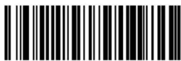
EAN-8 DECODING LEVELS = VERY CONSERVATIVE

EAN-8 DECODING LEVELS = SLIGHTLY MORE AGGRESSIVE
EAN-8 Decoding Levels (continued)
Remember to cover any unused bar codes on this and the facing page to ensure that the scanner reads only the bar code you intend to scan.
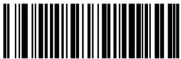
EAN-8 DECODING LEVELS = MODERATELY AGGRESSIVE
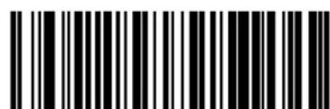
EAN-8 DECODING LEVELS = VERY AGGRESSIVE
EAN-8 Minimum Reads
Specifies the minimum number of consecutive times an EAN-8 label must be decoded before it is accepted as a good read.
To set this feature:
- Scan the SWITCH bar code.
- Scan the bar code representing the desired option below or on the following pages. You'll need to cover any unused bar codes on facing pages to ensure that the scanner reads only the bar code you intend to scan.
Complete the programming sequence by scanning the SWITCH bar code.


EAN-8 Minimum Reads (continued)
Remember to cover any unused bar codes on this and the facing page to ensure that the scanner reads only the bar code you intend to scan.


EAN-8 Minimum Segment Length
Specifies the minimum number of characters necessary in an EAN-8/JAN-8 label segment in order for the scanner to accept a label for decoding. Selectable from 5 to 15 characters.
To set this feature:
- Scan the SWITCH bar code.
- Scan the bar code representing the desired option below or on the following pages. You'll need to cover any unused bar codes on facing pages to ensure that the scanner reads only the bar code you intend to scan.
Complete the programming sequence by scanning the SWITCH bar code.

EAN-8 MINIMUM SEGMENT LENGTH = 5 CHARACTERS

EAN-8 MINIMUM SEGMENT LENGTH = 6 CHARACTERS
EAN-8 Minimum Segment Length (continued)
Remember to cover any unused bar codes on this and the facing page to ensure that the scanner reads only the bar code you intend to scan.
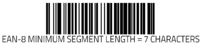

EAN-8 MINIMUM SEGMENT LENGTH = 8 CHARACTERS
EAN-8 Minimum Segment Length (continued)
Remember to cover any unused bar codes on this and the facing page to ensure that the scanner reads only the bar code you intend to scan.

EAN-8 MINIMUM SEGMENT LENGTH = 9 CHARACTERS

EAN-8 MINIMUM SEGMENT LENGTH = 10 CHARACTERS
EAN-8 Minimum Segment Length (continued)
Remember to cover any unused bar codes on this and the facing page to ensure that the scanner reads only the bar code you intend to scan.
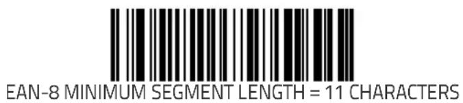

EAN-8 MINIMUM SEGMENT LENGTH = 12 CHARACTERS
EAN-8 Minimum Segment Length (continued)
Remember to cover any unused bar codes on this and the facing page to ensure that the scanner reads only the bar code you intend to scan.

EAN-8 MINIMUM SEGMENT LENGTH = 13 CHARACTERS

EAN-8 MINIMUM SEGMENT LENGTH = 14 CHARACTERS
EAN-8 Minimum Segment Length (continued)
Remember to cover any unused bar codes on this and the facing page to ensure that the scanner reads only the bar code you intend to scan.

Other UPC/EAN Options
The following pages contain other selectable features for UPC/EAN symbologies:
• Price Weight Check on page 311
• In-Store Label Minimum Reads on page 314
- Enable EAN Two Label on page 316
• EAN Two Label Minimum Reads on page 322
- Addons on page 331
Price Weight Check
Enables/disables calculation and verification of price/weight check digits. Applies to all UPC-A and EAN/JAN-13 labels with eligible ^1 Number System/First Character digits.
Options are:
• D i s a b l e
• 4-digit price/weight
- 5-digit price/weight
• 4-digit European price/weight
• 5-digit European price/weight
To set this feature:
- Scan the SWITCH bar code.
- Scan the bar code representing the desired option below or on the following pages. You'll need to cover any unused bar codes on facing pages to ensure that the scanner reads only the bar code you intend to scan.
- Complete the programming sequence by scanning the SWITCH bar code.

PRICE WEIGHT CHECK = DISABLE
- Price Weight Check generally applies to UPC-A labels with a Number System Digit of 2 and EAN/JAN-13 labels with a First Character of 2. There are a total of six flag digits corresponding to the six types. Checking applies depending upon which type is enabled.
Price Weight Check (continued)
Remember to cover any unused bar codes on this and the facing page to ensure that the scanner reads only the bar code you intend to scan.


PRICE WEIGHT CHECK = 5-DIGIT PRICE/WEIGHT
Price Weight Check (continued)
Remember to cover any unused bar codes on this and the facing page to ensure that the scanner reads only the bar code you intend to scan.

PRICE WEIGHT CHECK = 4-DIGIT EUROPEAN PRICE/WEIGHT

PRICE WEIGHT CHECK = 5-DIGIT EUROPEAN PRICE/WEIGHT
In-Store Label Minimum Reads
Specifies the minimum number of consecutive times an In-Store ^1 label must be decoded before it is accepted as a good read.
To set this feature:
- Scan the SWITCH bar code.
- Scan the bar code representing the desired option below or on the following pages. You'll need to cover any unused bar codes on facing pages to ensure that the scanner reads only the bar code you intend to scan.
Complete the programming sequence by scanning the SWITCH bar code.


- Instore labels are defined as UPC-A labels with a number-system character of 2 or 4 as well as EAN-8 and EAN-13 labels with a Flag1 character of 2 or an EAN-13 label starting with the three characters '980'.
In-Store Label Minimum Reads (continued)
Remember to cover any unused bar codes on this and the facing page to ensure that the scanner reads only the bar code you intend to scan.

IN-STORE MINIMUM READS = 3

IN-STORE MINIMUM READS = 4
Enable EAN Two Label
Enables/disables the ability of the scanner to decode EAN two-label pairs.
To set this feature:
- Scan the SWITCH bar code.
- Scan either the enable or disable bar code below. You'll need to cover any unused bar codes on this and the facing page to ensure that the scanner reads only the bar code you intend to scan.
- Complete the programming sequence by scanning the SWITCH bar code.
| Contact Customer Support for details about advanced programming for this feature. |

EAN TWO LABEL = DISABLE

EAN TWO LABEL = ENABLE
EAN Two Label Combined Transmission
Enables/disables the transmitting of an EAN two label pair as one label.
To set this feature:
- Scan the SWITCH bar code.
- Scan either the enable or disable bar code below. You'll need to cover any unused bar codes on this and the facing page to ensure that the scanner reads only the bar code you intend to scan.
- Complete the programming sequence by scanning the SWITCH bar code.
| Contact Customer Support for details about advanced programming for this feature. |


UPC/EAN Guard Insertion
Enables/Disables the ability of the scanner to insert either a missing leading or trailing guard on an otherwise complete UPC-A/EAN-13 segment it has received.
To set this feature:
- Scan the SWITCH bar code.
- Scan either the enable or disable bar code below. You'll need to cover any unused bar codes on this and the facing page to ensure that the scanner reads only the bar code you intend to scan.
- Complete the programming sequence by scanning the SWITCH bar code.


UPC/EAN GUARD INSERTION = ENABLE
UPC/EAN Stitch Exact Label Halves
When enabled, this allows the scanner the ability to stitch exact UPC-A / EAN-13 label haves with no overlapping characters.
To set this feature:
- Scan the SWITCH bar code.
- Scan either the enable or disable bar code below. You'll need to cover any unused bar codes on this and the facing page to ensure that the scanner reads only the bar code you intend to scan.
- Complete the programming sequence by scanning the SWITCH bar code.
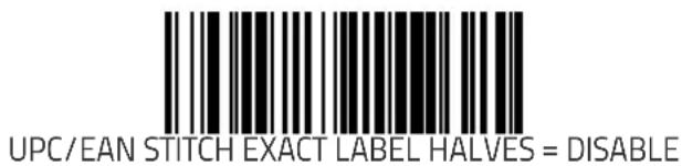

UPC/EAN STITCH EXACT LABEL HALVES = ENABLE
UPC/EAN Stitch Unlike Label Halves
When enabled, this allows the scanner the ability to stitch two UPC-A / EAN-13 label halves together that may contain differing characters.
To set this feature:
- Scan the SWITCH bar code.
- Scan either the enable or disable bar code below. You'll need to cover any unused bar codes on this and the facing page to ensure that the scanner reads only the bar code you intend to scan.
- Complete the programming sequence by scanning the SWITCH bar code.

UPC/EAN STITCH UNLIKE LABEL HALVES = DISABLE

UPC/EAN STITCH UNLIKE LABEL HALVES = ENABLE
UPC/EAN Character Reconstruction
Enables/Disables character reconstruction on UPC/EAN labels.
To set this feature:
- Scan the SWITCH bar code.
- Scan either the enable or disable bar code below. You'll need to cover any unused bar codes on this and the facing page to ensure that the scanner reads only the bar code you intend to scan.
- Complete the programming sequence by scanning the SWITCH bar code.

UPC/EAN CHARACTER RECONSTRUCTION = DISABLE

UPC/EAN CHARACTER RECONSTRUCTION = ENABLE
EAN Two Label Minimum Reads
Specifies the minimum number of consecutive times an EAN Two Label bar code must be decoded before it is accepted as a good read.
To set this feature:
- Scan the SWITCH bar code.
- Scan the bar code representing the desired option below or on the following pages. You'll need to cover any unused bar codes on facing pages to ensure that the scanner reads only the bar code you intend to scan.
Complete the programming sequence by scanning the SWITCH bar code.


EAN TWO LABEL MINIMUM READS = 2
EAN Two Label Minimum Reads (continued)
Remember to cover any unused bar codes on this and the facing page to ensure that the scanner reads only the bar code you intend to scan.

EAN TWO LABEL MINIMUM READS = 3

EAN TWO LABEL MINIMUM READS = 4
UPC/EAN Correlation
This feature enables/disables character correlation for UPC/EAN. To set this feature:
- Scan the SWITCH bar code.
- Scan your selection from the bar codes below. You'll need to cover any unused bar codes on this and the facing page to ensure that the scanner reads only the bar code you intend to scan.
Complete the programming sequence by scanning the SWITCH bar code.


UPC/EAN CORRELATION = ENABLE
UPC/EAN Minimum Segment Length
Specifies the minimum number of characters necessary in a UPC/EAN/JAN label segment in order for the scanner to accept a label for decoding. Selectable from 5 to 15 characters.
To set this feature:
- Scan the SWITCH bar code.
- Scan the bar code representing the desired option below or on the following pages. You'll need to cover any unused bar codes on facing pages to ensure that the scanner reads only the bar code you intend to scan.
Complete the programming sequence by scanning the SWITCH bar code.

UPC/EAN MINIMUM SEGMENT LENGTH = 5 CHARACTERS

UPC/EAN MINIMUM SEGMENT LENGTH = 6 CHARACTERS
UPC/EAN Minimum Segment Length (continued)
Remember to cover any unused bar codes on this and the facing page to ensure that the scanner reads only the bar code you intend to scan.

UPC/EAN MINIMUM SEGMENT LENGTH = 7 CHARACTERS

UPC/EAN MINIMUM SEGMENT LENGTH = 8 CHARACTERS
UPC/EAN Minimum Segment Length (continued)
Remember to cover any unused bar codes on this and the facing page to ensure that the scanner reads only the bar code you intend to scan.

UPC/EAN MINIMUM SEGMENT LENGTH = 9 CHARACTERS

UPC/EAN MINIMUM SEGMENT LENGTH = 10 CHARACTERS
UPC/EAN Minimum Segment Length (continued)
Remember to cover any unused bar codes on this and the facing page to ensure that the scanner reads only the bar code you intend to scan.

UPC/EAN MINIMUM SEGMENT LENGTH = 11 CHARACTERS

UPC/EAN MINIMUM SEGMENT LENGTH = 12 CHARACTERS
UPC/EAN Minimum Segment Length (continued)
Remember to cover any unused bar codes on this and the facing page to ensure that the scanner reads only the bar code you intend to scan.

UPC/EAN MINIMUM SEGMENT LENGTH = 13 CHARACTERS

UPC/EAN MINIMUM SEGMENT LENGTH = 14 CHARACTERS
UPC/EAN Minimum Segment Length (continued)
Remember to cover any unused bar codes on this and the facing page to ensure that the scanner reads only the bar code you intend to scan.

UPC/EAN MINIMUM SEGMENT LENGTH = 15 CHARACTERS
Addons
Add-ons (or supplemental characters) are commonly added to the end of UPC/EAN bar codes. The scanner will read the add-ons if they are enabled and in the field of view. Three add-on types are supported: 2-digit, 5-digit and Code 128 add-ons. Supported options are:
None — This option directs the scanner to ignore add-on portion of a UPC/EAN bar code but still read the main portion of the bar code.
2 Digits — The scanner will optionally read 2-digit add-ons with the UPC/EAN label.
5 Digits — The scanner will optionally read 5-digit add-ons with the UPC/EAN label.
Code 128 Add-on — The scanner will optionally read Code 128 add-ons with the UPC/EAN label.

Contact Customer Support for advanced programming of optional and conditional add-ons.
NOTE
To set this feature:
- Scan the SWITCH bar code.
- Scan the bar code representing the desired option on this and the following page. You'll need to cover any unused bar codes on facing pages to ensure that the scanner reads only the bar code you intend to scan.
- Complete the programming sequence by scanning the SWITCH bar code.
Addons (continued)
Remember to cover any unused bar codes on this and the facing page to ensure that the scanner reads only the bar code you intend to scan.
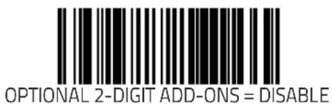

OPTIONAL 2-DIGIT ADD-ONS = ENABLE
Addons (continued)
Remember to cover any unused bar codes on this and the facing page to ensure that the scanner reads only the bar code you intend to scan.

OPTIONAL 5-DIGIT ADD-ONS = DISABLE

OPTIONAL 5-DIGIT ADD-ONS = ENABLE
Addons (continued)
Remember to cover any unused bar codes on this and the facing page to ensure that the scanner reads only the bar code you intend to scan.


OPTIONAL CODE 128 ADD-ONS = ENABLE
Addon Timer
When addons have been selected as optional, this feature sets the duration of time that the scanner can unsuccessfully look for an addon before proceeding to read a bar code. Timer duration is specified in 10ms increments.
To set the Addon Timer:
- Scan the SWITCH bar code.
- Scan the bar code, SET ADDON TIMER DURATION on page 335 below. You'll need to cover any unused bar codes on this and the facing page to ensure that the scanner reads only the bar code you intend to scan.
- Scan the appropriate digits from the keypad in Appendix C that represent the desired Addon Timer Duration. The selectable range is 1–10, which is the timeout in 10-millisecond increments. Pad all single and double digit numbers with leading zeroes to yield a three-digit entry (001–010).
Examples:
$$ 0 0 1 = 1 0 \mathrm{ms} $$
$$ 0 0 3 = 3 0 \mathrm{ms} $$
$$ 0 0 8 = 8 0 \mathrm{ms} $$
Complete the programming sequence by scanning the SWITCH bar code.

SET ADDON TIMER DURATION
2-Digit Add-ons Minimum Reads
Specifies the minimum number of times a 2-digit addon must be read before it is marked as valid and then combined with a base label.
To set this feature:
- Scan the SWITCH bar code.
- Scan the bar code representing the desired option below or on the following pages. You'll need to cover any unused bar codes on facing pages to ensure that the scanner reads only the bar code you intend to scan.
Complete the programming sequence by scanning the SWITCH bar code.

2-DIGIT ADD-ONS MINIMUM READS = 2

2-DIGIT ADD-ONS MINIMUM READS = 3
2-Digit Add-ons Minimum Reads (continued)
Remember to cover any unused bar codes on this and the facing page to ensure that the scanner reads only the bar code you intend to scan.
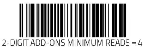
5-Digit Add-ons Minimum Reads
Specifies the minimum number of times a 5-digit addon must be read before it is marked as valid and then combined with a base label.
To set this feature:
- Scan the SWITCH bar code.
- Scan the bar code representing the desired option below or on the following pages. You'll need to cover any unused bar codes on facing pages to ensure that the scanner reads only the bar code you intend to scan.
Complete the programming sequence by scanning the SWITCH bar code.

5-DIGIT ADD-ONS MINIMUM READS = 1

5-DIGIT ADD-ONS MINIMUM READS = 2
5-Digit Add-ons Minimum Reads (continued)
Remember to cover any unused bar codes on this and the facing page to ensure that the scanner reads only the bar code you intend to scan.


5-DIGIT ADD-ONS MINIMUM READS = 4
Code 128 Add-ons Minimum Reads
Specifies the minimum number of times a Code 128 addon must be read before it is marked as valid and then combined with a base label.
To set this feature:
- Scan the SWITCH bar code.
- Scan the bar code representing the desired option below or on the following pages. You'll need to cover any unused bar codes on facing pages to ensure that the scanner reads only the bar code you intend to scan.
Complete the programming sequence by scanning the SWITCH bar code.

CODE 128 ADD-ONS MINIMUM READS = 1
CODE 128 ADD-ONS MINIMUM READS = 2
Code 128 Add-ons Minimum Reads (continued)
Remember to cover any unused bar codes on this and the facing page to ensure that the scanner reads only the bar code you intend to scan.
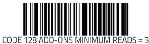

GTIN Enable
Enables/Disables the ability to convert UPCE, UPCA, EAN8, and EAN13 labels into the GTIN 14-character format.

If add-on information is present on the base label prior to the conversion taking place, the add-on information will be appended to the converted GTIN bar code.
To set this feature:
- Scan the SWITCH bar code.
- Scan either the enable or disable bar code below. You'll need to cover any unused bar codes on this and the facing page to ensure that the scanner reads only the bar code you intend to scan.
- Complete the programming sequence by scanning the SWITCH bar code.

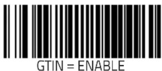
GTIN Label ID
This feature specifies a GTIN label ID to be added to bar code data when GTIN conversion is enabled.

NOTE
The programming feature, Label ID Control, designates whether the Label ID is transmitted as a prefix or suffix or if Label ID is disabled.
To set this feature:
- Scan the SWITCH bar code.
- Scan the bar code, SET GTIN LABEL ID on page 343 below. You'll need to cover any unused bar codes on this and the facing page to ensure the scanner reads only the bar code you intend to scan.
- Scan the appropriate digits from the keypad in Appendix that represent the desired Label ID characters; entered as two hex pairs. A table containing the ASCII Character Set on page 1 and their corresponding Hex Values is available in the inside back cover of this manual. ASCII parameters must be input by scanning a pair of hexadecimal digits for each character. Thus, to set a two-character value of AB, bar codes containing the digits '4', '1', '4', and '2' must be scanned. The selectable range for this option is any hex value from 00 to FF (for each of the two characters).
- Complete the programming sequence by scanning the SWITCH bar code.

SET GTIN LABEL ID
GTIN 2-Digit Supplemental Label ID
This feature specifies a GTIN label ID to be added to bar code data when GTIN conversion is enabled and 2-digit supplemental addon bar code labels are converted.

NOTE
The programming feature, Label ID Control, designates whether the Label ID is transmitted as a prefix or suffix or if Label ID is disabled.
To set this feature:
- Scan the SWITCH bar code.
- Scan the bar code, SET GTIN 2-DIGIT SUPPLEMENTAL LABEL ID on page 344 below. You'll need to cover any unused bar codes on this and the facing page to ensure the scanner reads only the bar code you intend to scan.
- Scan the appropriate digits from the keypad in Appendix that represent the desired Label ID characters; entered as two hex pairs. A table containing the ASCII Character Set on page 1 and their corresponding Hex Values is available in the inside back cover of this manual. ASCII parameters must be input by scanning a pair of hexadecimal digits for each character. Thus, to set a two-character value of AB, bar codes containing the digits '4', '1', '4', and '2' must be scanned. The selectable range for this option is any hex value from 00 to FF (for each of the two characters).
- Complete the programming sequence by scanning the SWITCH bar code.

SET GTIN 2-DIGIT SUPPLEMENTAL LABEL ID
GTIN 5-Digit Supplemental Label ID
This feature specifies a GTIN label ID to be added to bar code data when GTIN conversion is enabled and 5-digit supplemental addon bar code labels are converted.

NOTE
The programming feature, Label ID Control, designates whether the Label ID is transmitted as a prefix or suffix or if Label ID is disabled.
To set this feature:
- Scan the SWITCH bar code.
- Scan the bar code, SET GTIN 5-DIGIT SUPPLEMENTAL LABEL ID on page 345 below. You'll need to cover any unused bar codes on this and the facing page to ensure the scanner reads only the bar code you intend to scan.
- Scan the appropriate digits from the keypad in Appendix that represent the desired Label ID characters; entered as two hex pairs. A table containing the ASCII Character Set on page 1 and their corresponding Hex Values is available in the inside back cover of this manual. ASCII parameters must be input by scanning a pair of hexadecimal digits for each character. Thus, to set a two-character value of AB, bar codes containing the digits '4', '1', '4', and '2' must be scanned. The selectable range for this option is any hex value from 00 to FF (for each of the two characters).
- Complete the programming sequence by scanning the SWITCH bar code.
SET GTIN 5-DIGIT SUPPLEMENTAL LABEL ID
GTIN Code 128 Supplemental Label ID
This feature specifies a GTIN label ID to be added to bar code data when GTIN conversion is enabled and Code 128 supplemental addon bar code labels are converted

NOTE
The programming feature, Label ID Control, designates whether the Label ID is transmitted as a prefix or suffix or if Label ID is disabled.
To set this feature:
- Scan the SWITCH bar code.
- Scan the bar code, SET GTIN CODE 128 SUPPLEMENTAL LABEL ID on page 346 below. You'll need to cover any unused bar codes on this and the facing page to ensure the scanner reads only the bar code you intend to scan.
- Scan the appropriate digits from the keypad in Appendix that represent the desired Label ID characters; entered as two hex pairs. A table containing the ASCII Character Set on page 1 and their corresponding Hex Values is available in the inside back cover of this manual. ASCII parameters must be input by scanning a pair of hexadecimal digits for each character. Thus, to set a two-character value of AB, bar codes containing the digits '4', '1', '4', and '2' must be scanned. The selectable range for this option is any hex value from 00 to FF (for each of the two characters).
- Complete the programming sequence by scanning the SWITCH bar code.
SET GTIN CODE 128 SUPPLEMENTAL LABEL ID
DataBar Omnidirectional Enable
Enables/disables the ability of the scanner to decode DataBar Omnidirectional labels.

NOTE
This value-added feature is a factory-programmed option. Contact your dealer for information about upgrading your system to include this advanced capability.
To set this feature:
- Scan the SWITCH bar code.
- Scan either the enable or disable bar code below. You'll need to cover any unused bar codes on this and the facing page to ensure that the scanner reads only the bar code you intend to scan.
- Complete the programming sequence by scanning the SWITCH bar code.


DataBar Omnidirectional/EAN-128 Emulation
Enables/disables the ability of DataBar Omnidirectional to be transmitted as EAN-128.
To set this feature:
- Scan the SWITCH bar code.
- Scan either the enable or disable bar code below. You'll need to cover any unused bar codes on this and the facing page to ensure that the scanner reads only the bar code you intend to scan.
- Complete the programming sequence by scanning the SWITCH bar code.

DataBar Omnidirectional/EAN-128 EMULATION = DISABLE

DataBar Omnidirectional/EAN-128 EMULATION = ENABLE
DataBar Omnidirectional Label ID
This feature specifies an DataBar Omnidirectional label ID to be added to bar code data.
To set this feature:

NOTE
The programming feature, Label ID Control, designates whether the Label ID is transmitted as a prefix or suffix or if Label ID is disabled.
To set this feature:
- Scan the SWITCH bar code.
- Scan the bar code, SET DataBar Omnidirectional LABEL ID on page 349 below. You'll need to cover any unused bar codes on this and the facing page to ensure the scanner reads only the bar code you intend to scan.
-
Scan the appropriate digits from the keypad in Appendix C that represent the desired Label ID characters; entered as two hex pairs. A table containing the ASCII Character Set on page 1 and their corresponding Hex Values is available in the inside back cover of this manual. ASCII parameters must be input by scanning a pair of hexadecimal digits for each character. Thus, to set a two-character value of AB, bar codes containing the digits '4', '1', '4', and '2' must be scanned. The selectable range for this option is any hex value from 00 to FF.
-
Complete the programming sequence by scanning the SWITCH bar code.

SET DataBar Omnidirectional LABEL ID
DataBar Omnidirectional Minimum Reads
Specifies the minimum number of consecutive times an DataBar Omnidirectional label must be decoded before it is accepted as a good read.
To set this feature:
- Scan the SWITCH bar code.
- Scan the bar code representing the desired option below or on the following pages. You'll need to cover any unused bar codes on facing pages to ensure that the scanner reads only the bar code you intend to scan.
Complete the programming sequence by scanning the SWITCH bar code.

DataBar Omnidirectional MINIMUM READS = 1

DataBar Omnidirectional MINIMUM READS = 2
DataBar Omnidirectional Minimum Reads (continued)
Remember to cover any unused bar codes on this and the facing page to ensure that the scanner reads only the bar code you intend to scan.


DataBar Omnidirectional MINIMUM READS = 4
DataBar Expanded Enable
Enables/disables the ability of the scanner to decode DataBar Expanded labels.

NOTE
This value-added feature is a factory-programmed option. Contact your dealer for information about upgrading your system to include this advanced capability.
To set this feature:
- Scan the SWITCH bar code.
- Scan either the enable or disable bar code below. You'll need to cover any unused bar codes on this and the facing page to ensure that the scanner reads only the bar code you intend to scan.
- Complete the programming sequence by scanning the SWITCH bar code.

DataBar Expanded = DISABLE

DataBar Expanded = ENABLE
DataBar Expanded EAN-128 Emulation
Enables/disables EAN-128 emulation for DataBar Expanded.
To set this feature:
- Scan the SWITCH bar code.
- Scan either the enable or disable bar code below. You'll need to cover any unused bar codes on this and the facing page to ensure that the scanner reads only the bar code you intend to scan.
- Complete the programming sequence by scanning the SWITCH bar code.

DataBar Expanded/EAN-128 EMULATION = DISABLE

DataBar Expanded/EAN-128 EMULATION = ENABLE
DataBar Expanded Label ID
This feature specifies an DataBar Expanded label ID to be added to bar code data.

NOTE
The programming feature, Label ID Control, designates whether the Label ID is transmitted as a prefix or suffix or if Label ID is disabled.
To set this feature:
- Scan the SWITCH bar code.
- Scan the bar code, SET DataBar Expanded LABEL ID on page 354 below. You'll need to cover any unused bar codes on this and the facing page to ensure the scanner reads only the bar code you intend to scan.
-
Scan the appropriate digits from the keypad in Appendix C that represent the desired Label ID characters; entered as two hex pairs. A table containing the ASCII Character Set on page 1 and their corresponding Hex Values is available in the inside back cover of this manual. ASCII parameters must be input by scanning a pair of hexadecimal digits for each character. Thus, to set a two-character value of AB, bar codes containing the digits '4', '1', '4', and '2' must be scanned. The selectable range for this option is any hex value from 00 to FF.
-
Complete the programming sequence by scanning the SWITCH bar code.
SET DataBar Expanded LABEL ID
DataBar Expanded Length Control
This feature specifies either variable-length or fixed-length decoding for DataBar Expanded.
To set this feature:
- Scan the SWITCH bar code.
- Scan your selection from the bar codes below. You'll need to cover any unused bar codes on this and the facing page to ensure that the scanner reads only the bar code you intend to scan.
- Complete the programming sequence by scanning the SWITCH bar code.
You must now set the features DataBar Expanded Length 1 on page 356 and DataBar Expanded Length 2 on page 357.
NOTE

DataBar Expanded LENGTH CONTROL = VARIABLE-LENGTH

DataBar Expanded LENGTH CONTROL = FIXED-LENGTH
DataBar Expanded Length 1
Length 1 is the minimum label length if in variable length mode, or the first fixed length if in fixed length mode (see DataBar Expanded Length Control on page 355). Length includes the barcode's check and data characters.
To set this feature:
- Scan the SWITCH bar code.
- Scan the bar code, SET DataBar Expanded LENGTH 1 on page 356 below. You'll need to cover any unused bar codes on this and the facing page to ensure that the scanner reads only the bar code you intend to scan.
- Scan the appropriate digits from the keypad in Appendix C that represent the desired label length. The selectable range for this option is 01 to 74. Pad all single and double digit numbers with leading zeroes to yield a three-digit entry (001-074).
- Complete the programming sequence by scanning the SWITCH bar code.

SET DataBar Expanded LENGTH 1
DataBar Expanded Length 2
Length 2 is the maximum label length if in variable length mode, or the second fixed length if in fixed length mode (see DataBar Expanded Length Control on page 355). Length includes the barcode's check and data characters.
To set this feature:
- Scan the SWITCH bar code.
- Scan the bar code, SET DataBar Expanded LENGTH 2 on page 357 below. You'll need to cover any unused bar codes on this and the facing page to ensure that the scanner reads only the bar code you intend to scan.
- Scan the appropriate digits from the keypad in Appendix C that represent the desired label length. A setting of 000 will ignore this length (only one fixed length), otherwise, the selectable range for this option is 001 to 074. Pad all single and double digit numbers with leading zeroes to yield a three-digit entry (001–074).
- Complete the programming sequence by scanning the SWITCH bar code.

SET DataBar Expanded LENGTH 2
DataBar Expanded Minimum Reads
Specifies the minimum number of consecutive times an DataBar Expanded label must be decoded before it is accepted as a good read.
To set this feature:
- Scan the SWITCH bar code.
- Scan the bar code representing the desired option below or on the following pages. You'll need to cover any unused bar codes on facing pages to ensure that the scanner reads only the bar code you intend to scan.
Complete the programming sequence by scanning the SWITCH bar code.

DataBar Expanded MINIMUM READS = 1

DataBar Expanded MINIMUM READS = 2
DataBar Expanded Minimum Reads (continued)
Remember to cover any unused bar codes on this and the facing page to ensure that the scanner reads only the bar code you intend to scan.


DataBar Expanded MINIMUM READS = 4
Code 39 Enable
Enables/disables the ability of the scanner to decode Code 39 labels.
To set this feature:
- Scan the SWITCH bar code.
- Scan either the enable or disable bar code below. You'll need to cover any unused bar codes on this and the facing page to ensure that the scanner reads only the bar code you intend to scan.
- Complete the programming sequence by scanning the SWITCH bar code.
CODE 39 = DISABLE
CODE 39 = ENABLE
Code 39 Start Stop Character Transmission
Enables/disables transmission of Code 39 start and stop characters.

NOTE
This feature applies only when Code 39 Check Character Calculation on page 362 is enabled.
To set this feature:
- Scan the SWITCH bar code.
- Scan either the enable or disable bar code below. You'll need to cover any unused bar codes on this and the facing page to ensure that the scanner reads only the bar code you intend to scan.
- Complete the programming sequence by scanning the SWITCH bar code.
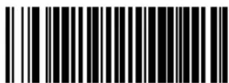
CODE 39 START STOP CHARACTER TRANSMISSION = DISABLE

CODE 39 START STOP CHARACTER TRANSMISSION = ENABLE
Code 39 Check Character Calculation
Enables/disables calculation and verification of an optional Code 39 check character. When disabled, any check character in label is treated as a data character.

NOTE
If check calculation is disabled, the risk is increased that a misread can occur.
In particular, if you are using variable length stitching, it is important to use check character calculation to prevent misreads.
To set this feature:
- Scan the SWITCH bar code.
- Scan either the enable or disable bar code below. You'll need to cover any unused bar codes on this and the facing page to ensure that the scanner reads only the bar code you intend to scan.
- Complete the programming sequence by scanning the SWITCH bar code.

CODE 39 CHECK CHARACTER CALCULATION = DISABLE
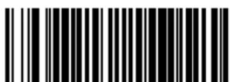
CODE 39 CHECK CHARACTER CALCULATION = ENABLE
Code 39 Check Character Transmission
Enables/disables transmission of optional Code 39 check character. To set this feature:
- Scan the SWITCH bar code.
- Scan either the enable or disable bar code below. You'll need to cover any unused bar codes on this and the facing page to ensure that the scanner reads only the bar code you intend to scan.
- Complete the programming sequence by scanning the SWITCH bar code.
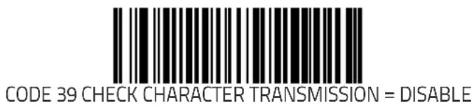
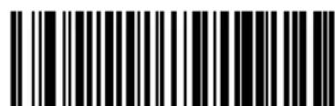
CODE 39 CHECK CHARACTER TRANSMISSION = ENABLE
Code 39 Full ASCII
Enables/disables the ability of the scanner to translate to Code 39 full ASCII labels.
To set this feature:
- Scan the SWITCH bar code.
- Scan either the enable or disable bar code below. You'll need to cover any unused bar codes on this and the facing page to ensure that the scanner reads only the bar code you intend to scan.
- Complete the programming sequence by scanning the SWITCH bar code.


Code 39 Label ID

NOTE
This feature specifies a Code 39 label ID to be added to bar code data.
The programming feature, Label ID Control, designates whether the Label ID is transmitted as a prefix or suffix or if Label ID is disabled.
To set this feature:
- Scan the SWITCH bar code.
- Scan the bar code, SET CODE 39 LABEL ID on page 365 below. You'll need to cover any unused bar codes on this and the facing page to ensure the scanner reads only the bar code you intend to scan.
-
Scan the appropriate digits from the keypad in Appendix C that represent the desired Label ID characters; entered as two hex pairs. A table containing the ASCII Character Set on page 1 and their corresponding Hex Values is available in the inside back cover of this manual. ASCII parameters must be input by scanning a pair of hexadecimal digits for each character. Thus, to set a two-character value of AB, bar codes containing the digits '4', '1', '4', and '2' must be scanned. The selectable range for this option is any hex value from 00 to FF.
-
Complete the programming sequence by scanning the SWITCH bar code.
SET CODE 39 LABEL ID
Code 39 Require Quiet Zones
When enabled, this feature requires that quiet zones (margins) be present for Code 39 labels. When disabled, quiet zones are optional.
To set this feature:
- Scan the SWITCH bar code.
- Scan either the enable or disable bar code below. You'll need to cover any unused bar codes on this and the facing page to ensure that the scanner reads only the bar code you intend to scan.
- Complete the programming sequence by scanning the SWITCH bar code.

CODE 39 REQUIRE QUIET ZONES = DISABLE

CODE 39 REQUIRE QUIET ZONES = ENABLE
Code 39 Length Control
This feature specifies whether variable-length or fixed-length decoding will be set for Code 39.
To set this feature:
- Scan the SWITCH bar code.
- Scan your selection from the bar codes below. You'll need to cover any unused bar codes on this and the facing page to ensure that the scanner reads only the bar code you intend to scan.
- Complete the programming sequence by scanning the SWITCH bar code.
You must now set the features Code 39 Length 1 on page 368 and Code 39 Length 2 on page 369.
When using variable length stitching, it is important to enable Code 39 Check Character Calculation on page 362 to prevent misreads.
NOTE

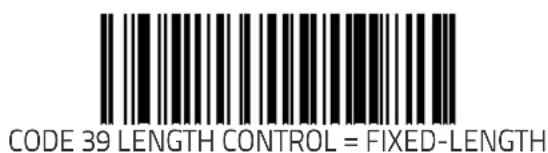
Code 39 Length 1
Length 1 is the minimum label length if in variable length mode, or the first fixed length if in fixed length mode (see Code 39 Length Control on page 367). Length includes the barcode's check and data characters.
To set this feature:
- Scan the SWITCH bar code.
- Scan the bar code, SET CODE 39 LENGTH 1 on page 368 below. You'll need to cover any unused bar codes on this and the facing page to ensure that the scanner reads only the bar code you intend to scan.
- Scan the appropriate digits from the keypad in Appendix C that represent the desired label length. The selectable range for this option is 001 to 050. Pad all single and double digit numbers with leading zeroes to yield a three-digit entry (001–050).
- Complete the programming sequence by scanning the SWITCH bar code.
Code 39 Length 2
Length 2 is the maximum label length if in variable length mode, or the second fixed length if in fixed length mode (see Code 39 Length Control on page 367). Length includes the barcode's check and data characters.
To set this feature:
- Scan the SWITCH bar code.
- Scan the bar code, SET CODE 39 LENGTH 2 on page 369 below. You'll need to cover any unused bar codes on this and the facing page to ensure that the scanner reads only the bar code you intend to scan.
- Scan the appropriate digits from the keypad in Appendix C that represent the desired fixed label length. A setting of 000 will ignore this length (only one fixed length), otherwise, the selectable range for this option is 001 to 050. Pad all single and double digit numbers with leading zeroes to yield a three-digit entry (001–050).
- Complete the programming sequence by scanning the SWITCH bar code.
Code 39 Correlation
This feature enables/disables character correlation for Code 39.
To set this feature:
- Scan the SWITCH bar code.
- Scan your selection from the bar codes below. You'll need to cover any unused bar codes on this and the facing page to ensure that the scanner reads only the bar code you intend to scan.
Complete the programming sequence by scanning the SWITCH bar code.

CODE 39 CORRELATION = DISABLE

CODE 39 CORRELATION = ENABLE
Code 39 Stitching
Enables/disables stitching for Code 39 labels. When parts of a Code 39 bar code are presented to the scanner with this feature enabled, the bar code parts will be assembled by the scanner's software, and the data will be decoded if all bar code proofing requirements are met.
To set this feature:
- Scan the SWITCH bar code.
- Scan your selection from the bar codes below. You'll need to cover any unused bar codes on this and the facing page to ensure that the scanner reads only the bar code you intend to scan.
Complete the programming sequence by scanning the SWITCH bar code.

CODE 39 STITCHING = DISABLE

CODE 39 STITCHING = ENABLE
Code 39 Minimum Reads
Specifies the minimum number of consecutive times a Code 39 label must be decoded before it is accepted as a good read.
To set this feature:
- Scan the SWITCH bar code.
- Scan the bar code representing the desired option below or on the following pages. You'll need to cover any unused bar codes on facing pages to ensure that the scanner reads only the bar code you intend to scan.
Complete the programming sequence by scanning the SWITCH bar code.

CODE 39 MINIMUM READS = 1

CODE 39 MINIMUM READS = 2
Code 39 Minimum Reads (continued)
Remember to cover any unused bar codes on this and the facing page to ensure that the scanner reads only the bar code you intend to scan.
CODE 39 MINIMUM READS = 3

CODE 39 MINIMUM READS = 4
Pharmacode 39 Enable
Enables/disables the ability of the scanner to decode Italian Pharmacode 39 labels.
To set this feature:
- Scan the SWITCH bar code.
- Scan either the enable or disable bar code below. You'll need to cover any unused bar codes on this and the facing page to ensure that the scanner reads only the bar code you intend to scan.
- Complete the programming sequence by scanning the SWITCH bar code.
PHARMACODE 39 = DISABLE
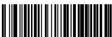
PHARMACODE 39 = ENABLE
Pharmacode 39 Start Stop Character Transmission
Enables/ disables transmission of start and stop characters for Pharmacode 39.
To set this feature:
- Scan the SWITCH bar code.
- Scan either the enable or disable bar code below. You'll need to cover any unused bar codes on this and the facing page to ensure that the scanner reads only the bar code you intend to scan.
- Complete the programming sequence by scanning the SWITCH bar code.

PHARMACODE 39 START STOP CHARACTER TRANSMISSION = DISABLE

PHARMACODE 39 START STOP CHARACTER TRANSMISSION = ENABLE
Pharmacode 39 Check Character Transmission
Enables/disables transmission of Pharmacode 39 check character. To set this feature:
- Scan the SWITCH bar code.
- Scan either the enable or disable bar code below. You'll need to cover any unused bar codes on this and the facing page to ensure that the scanner reads only the bar code you intend to scan.
- Complete the programming sequence by scanning the SWITCH bar code.

PHARMACODE 39 CHECK CHARACTER TRANSMISSION = DISABLE

PHARMACODE 39 CHECK CHARACTER TRANSMISSION = ENABLE
Pharmacode 39 Label ID
This feature specifies a Pharmacode 39 label ID to be added to bar code data.

NOTE
The programming feature, Label ID Control, designates whether the Label ID is transmitted as a prefix or suffix or if Label ID is disabled.
To set this feature:
- Scan the SWITCH bar code.
- Scan the bar code, SET PHARMACODE 39 LABEL ID on page 377 below. You'll need to cover any unused bar codes on this and the facing page to ensure the scanner reads only the bar code you intend to scan.
-
Scan the appropriate digits from the keypad in Appendix C that represent the desired Label ID characters; entered as two hex pairs. A table containing the ASCII Character Set on page 1 and their corresponding Hex Values is available in the inside back cover of this manual. ASCII parameters must be input by scanning a pair of hexadecimal digits for each character. Thus, to set a two-character value of AB, bar codes containing the digits '4', '1', '4', and '2' must be scanned. The selectable range for this option is any hex value from 00 to FF.
-
Complete the programming sequence by scanning the SWITCH bar code.

SET PHARMACODE 39 LABEL ID
Code 128 Enable
Enables/disables ^1 the ability of the scanner to decode Code 128 labels.
To set this feature:
- Scan the SWITCH bar code.
- Scan either the enable or disable bar code below. You'll need to cover any unused bar codes on this and the facing page to ensure that the scanner reads only the bar code you intend to scan.
- Complete the programming sequence by scanning the SWITCH bar code.
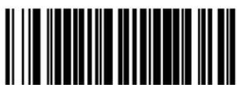
CODE 128 = DISABLE

CODE 128 = ENABLE
- Exception: The Code 128 symbology is always enabled with regard to scanning/reading the special C128 programming bar codes provided in this manual.
Code 128 Transmit Function Characters
Enables/disables transmission of Code 128 function characters 1, 2, 3, and 4.

NOTE
Disabled is the recommended setting for all interfaces.
To set this feature:
- Scan the SWITCH bar code.
- Scan either the enable or disable bar code below. You'll need to cover any unused bar codes on this and the facing page to ensure that the scanner reads only the bar code you intend to scan.
- Complete the programming sequence by scanning the SWITCH bar code.

CODE 128 TRANSMIT FUNCTION CHARACTERS = DISABLE

CODE 128 TRANSMIT FUNCTION CHARACTERS = ENABLE
Convert Code 128 to Code 39
Enables/disables conversion of Code 128 labels to Code 39.
To set this feature:
- Scan the SWITCH bar code.
- Scan either the enable or disable bar code below. You'll need to cover any unused bar codes on this and the facing page to ensure that the scanner reads only the bar code you intend to scan.
- Complete the programming sequence by scanning the SWITCH bar code.

CONVERT CODE 128 TO CODE 39 = DISABLE

CONVERT CODE 128 TO CODE 39 = ENABLE
Code 128 Label ID

NOTE
This feature specifies a Code 128 label ID to be added to bar code data..
The programming feature, Label ID Control, designates whether the Label ID is transmitted as a prefix or suffix or if Label ID is disabled.
To set this feature:
- Scan the SWITCH bar code.
- Scan the bar code, SET CODE 128 LABEL ID on page 381 below. You'll need to cover any unused bar codes on this and the facing page to ensure the scanner reads only the bar code you intend to scan.
-
Scan the appropriate digits from the keypad in Appendix C that represent the desired Label ID characters; entered as two hex pairs. A table containing the ASCII Character Set on page 1 and their corresponding Hex Values is available in the inside back cover of this manual. ASCII parameters must be input by scanning a pair of hexadecimal digits for each character. Thus, to set a two-character value of AB, bar codes containing the digits '4', '1', '4', and '2' must be scanned. The selectable range for this option is any hex value from 00 to FF.
-
Complete the programming sequence by scanning the SWITCH bar code.
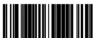
SET CODE 128 LABEL ID
Code 128 Length Control
This feature specifies whether variable-length or fixed-length decoding will be set for Code 128.
To set this feature:
- Scan the SWITCH bar code.
- Scan your selection from the bar codes below. You'll need to cover any unused bar codes on this and the facing page to ensure that the scanner reads only the bar code you intend to scan.
- Complete the programming sequence by scanning the SWITCH bar code.
You must now set the features Code 128 Length 1 on page 383 and Code 128 Length 2 on page 384.
NOTE

CODE 128 LENGTH CONTROL = VARIABLE-LENGTH

CODE 128 LENGTH CONTROL = FIXED-LENGTH
Code 128 Length 1
Length 1 is the minimum label length if in variable length mode, or the first fixed length if in fixed length mode (see Code 128 Length Control on page 382). Length includes the barcode's check and data characters.
To set this feature:
- Scan the SWITCH bar code.
- Scan the bar code, SET CODE 128 LENGTH 1 on page 383 below. You'll need to cover any unused bar codes on this and the facing page to ensure that the scanner reads only the bar code you intend to scan.
- Scan the appropriate digits from the keypad in Appendix C that represent the desired label length. The selectable range for this option is 001 to 080. Pad all single and double digit numbers with leading zeroes to yield a three-digit entry (001–080).
- Complete the programming sequence by scanning the SWITCH bar code.

Code 128 Length 2
Length 2 is the maximum label length if in variable length mode, or the second fixed length if in fixed length mode (see Code 128 Length Control on page 382). Length includes the barcode's check and data characters.
To set this feature:
- Scan the SWITCH bar code.
- Scan the bar code, SET CODE 128 LENGTH 2 on page 384 below. You'll need to cover any unused bar codes on this and the facing page to ensure that the scanner reads only the bar code you intend to scan.
- Scan the appropriate digits from the keypad in Appendix C that represent the desired label length. A setting of 000 will ignore this length (only one fixed length), otherwise, the selectable range for this option is 001 to 080. Pad all single and double digit numbers with leading zeroes to yield a three-digit entry (001–080).
- Complete the programming sequence by scanning the SWITCH bar code.
Code 128 Correlation
This feature enables/disables character correlation for Code 128. To set this feature:
- Scan the SWITCH bar code.
- Scan your selection from the bar codes below. You'll need to cover any unused bar codes on this and the facing page to ensure that the scanner reads only the bar code you intend to scan.
Complete the programming sequence by scanning the SWITCH bar code.

CODE 128 CORRELATION = DISABLE

CODE 128 CORRELATION = ENABLE
Code 128 Stitching
Enables/disables stitching for Code 128 labels. When parts of a Code 128 bar code are presented to the scanner with this feature enabled, the bar code parts will be assembled by the scanner's software, and the data will be decoded if all bar code proofing requirements are met.
To set this feature:
- Scan the SWITCH bar code.
- Scan your selection from the bar codes below. You'll need to cover any unused bar codes on this and the facing page to ensure that the scanner reads only the bar code you intend to scan.
Complete the programming sequence by scanning the SWITCH bar code.

CODE 128 STITCHING = DISABLE

CODE 128 STITCHING = ENABLE
Code 128 Minimum Reads
Specifies the minimum number of consecutive times a Code 128 label must be decoded before it is accepted as a good read.
To set this feature:
- Scan the SWITCH bar code.
- Scan the bar code representing the desired option below or on the following pages. You'll need to cover any unused bar codes on facing pages to ensure that the scanner reads only the bar code you intend to scan.
Complete the programming sequence by scanning the SWITCH bar code.


Code 128 Minimum Reads (continued)
Remember to cover any unused bar codes on this and the facing page to ensure that the scanner reads only the bar code you intend to scan.

CODE 128 MINIMUM READS = 3
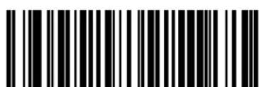
CODE 128 MINIMUM READS = 4
EAN-128 Enable
Enables/disables the ability of the scanner to decode EAN-128 labels. When disabled, EAN128 labels are transmitted in Code128 data format. When enabled, EAN128 labels are transmitted in EAN128 data format
To set this feature:
- Scan the SWITCH bar code.
- Scan either the enable or disable bar code below. You'll need to cover any unused bar codes on this and the facing page to ensure that the scanner reads only the bar code you intend to scan.
- Complete the programming sequence by scanning the SWITCH bar code.

EAN-128 = DISABLE
EAN-128 = ENABLE
EAN-128 Label ID
This feature specifies an EAN-128 label ID to be added to bar code data..

The programming feature, Label ID Control, designates whether the Label ID is transmitted as a prefix or suffix or if Label ID is disabled.
NOTE
To set this feature:
- Scan the SWITCH bar code.
- Scan the bar code, SET EAN-128 LABEL ID on page 390 below. You'll need to cover any unused bar codes on this and the facing page to ensure the scanner reads only the bar code you intend to scan.
-
Scan the appropriate digits from the keypad in Appendix C that represent the desired Label ID characters; entered as two hex pairs. A table containing the ASCII Character Set on page 1 and their corresponding Hex Values is available in the inside back cover of this manual. ASCII parameters must be input by scanning a pair of hexadecimal digits for each character. Thus, to set a two-character value of AB, bar codes containing the digits '4', '1', '4', and '2' must be scanned. The selectable range for this option is any hex value from 00 to FF.
-
Complete the programming sequence by scanning the SWITCH bar code.

SET EAN-128 LABEL ID
Interleaved 2 of 5 (1 2 of 5) Enable
Enables/disables the ability of the scanner to decode Interleaved 2 of 5 labels.
To set this feature:
- Scan the SWITCH bar code.
- Scan either the enable or disable bar code below. You'll need to cover any unused bar codes on this and the facing page to ensure that the scanner reads only the bar code you intend to scan.
- Complete the programming sequence by scanning the SWITCH bar code.

I 2 OF 5 = DISABLE

12 OF 5 = ENABLE
I 2 of 5 Check Character Calculation
Enables/disables calculation and verification of an optional Inter-leaved 2 of 5 check character.

NOTE
If check character calculation is disabled, the risk is increased that a misread can occur. When disabled, any check characters in a bar code are treated as data characters.
To set this feature:
- Scan the SWITCH bar code.
- Scan either the enable or disable bar code below. You'll need to cover any unused bar codes on this and the facing page to ensure that the scanner reads only the bar code you intend to scan.
- Complete the programming sequence by scanning the SWITCH bar code.

12 of 5 CHECK CHARACTER CALCULATION = DISABLE

12 of 5 CHECK CHARACTER CALCULATION = ENABLE
I 2 of 5 Check Character Transmission
Enables/disables transmission of an optional Interleaved 2 of 5 check character.

NOTE
This feature applies only when 12 of 5 Check Character Calculation on page 392 is enabled.
To set this feature:
- Scan the SWITCH bar code.
- Scan either the enable or disable bar code below. You'll need to cover any unused bar codes on this and the facing page to ensure that the scanner reads only the bar code you intend to scan.
- Complete the programming sequence by scanning the SWITCH bar code.


I 2 of 5 Label ID
This feature specifies an I 2 of 5 label ID to be added to bar code data..

NOTE
The programming feature, Label ID Control, designates whether the Label ID is transmitted as a prefix or suffix or if Label ID is disabled.
To set this feature:
- Scan the SWITCH bar code.
- Scan the bar code, SET I 2 of 5 LABEL ID on page 394 below. You'll need to cover any unused bar codes on this and the facing page to ensure the scanner reads only the bar code you intend to scan.
-
Scan the appropriate digits from the keypad in Appendix C that represent the desired Label ID characters; entered as two hex pairs. A table containing the ASCII Character Set on page 1 and their corresponding Hex Values is available in the inside back cover of this manual. ASCII parameters must be input by scanning a pair of hexadecimal digits for each character. Thus, to set a two-character value of AB, bar codes containing the digits '4', '1', '4', and '2' must be scanned. The selectable range for this option is any hex value from 00 to FF.
-
Complete the programming sequence by scanning the SWITCH bar code.

SET12 of 5 LABEL ID
12 of 5 Length Control
This feature specifies whether variable-length or fixed-length decoding will be set for 12 of 5.
To set this feature:
- Scan the SWITCH bar code.
- Scan your selection from the bar codes below. You'll need to cover any unused bar codes on this and the facing page to ensure that the scanner reads only the bar code you intend to scan.
- Complete the programming sequence by scanning the SWITCH bar code.
You must now set the features | 2 of 5 Length 1 on page 396 and | 2 of 5 Length 2 on page 397.
NOTE

I 2 OF 5 LENGTH CONTROL = VARIABLE-LENGTH

12 OF 5 LENGTH CONTROL = FIXED-LENGTH
I 2 of 5 Length 1
Length 1 is the minimum label length if in variable length mode, or the first fixed length if in fixed length mode (see 12 of 5 Length Control on page 395). Length includes the barcode's check and data characters.
To set this feature:
- Scan the SWITCH bar code.
- Scan the bar code, SET I 2 of 5 LENGTH 1 on page 396 below. You'll need to cover any unused bar codes on this and the facing page to ensure that the scanner reads only the bar code you intend to scan.
- Scan the appropriate digits from the keypad in Appendix C that represent the desired label length. The selectable range for this option is 002 to 050, even numbers only. Pad all single and double digit numbers with leading zeroes to yield a three-digit entry (002–050).
- Complete the programming sequence by scanning the SWITCH bar code.
12 of 5 Length 2
Length 2 is the maximum label length if in variable length mode, or the second fixed length if in fixed length mode (see 1.2 of 5 Length Control on page 395). Length includes the barcode's check and data characters.
To set this feature:
- Scan the SWITCH bar code.
- Scan the bar code, SET 1 2 of 5 LENGTH 2 on page 397 below. You'll need to cover any unused bar codes on this and the facing page to ensure that the scanner reads only the bar code you intend to scan.
-
Scan the appropriate digits from the keypad in Appendix C that represent the desired label length. A setting of 000 will ignore this length (only one fixed length), otherwise, the selectable range for this option is 002 to 050, even numbers only. Pad all single and double digit numbers with leading zeroes to yield a three-digit entry (002–050).
-
Complete the programming sequence by scanning the SWITCH bar code.

SET12 of 5 LENGTH 2
I 2 of 5 Correlation
This feature enables/disables character correlation for 12 of 5. To set this feature:
- Scan the SWITCH bar code.
- Scan your selection from the bar codes below. You'll need to cover any unused bar codes on this and the facing page to ensure that the scanner reads only the bar code you intend to scan.
Complete the programming sequence by scanning the SWITCH bar code.


12 of 5 Stitching
Enables/disables stitching for 12 of 5 labels. When parts of an 12 of 5 bar code are presented to the scanner with this feature enabled, the bar code parts will be assembled by the scanner's software, and the data will be decoded if all bar code proofing requirements are met.
To set this feature:
- Scan the SWITCH bar code.
- Scan your selection from the bar codes below. You'll need to cover any unused bar codes on this and the facing page to ensure that the scanner reads only the bar code you intend to scan.
- Complete the programming sequence by scanning the SWITCH bar code.
12 of 5 Stitching operates using fixed lengths ONLY. 12 of 5 Length 1 on page 396 and/or 12 of 5 Length 2 on page 397 must be properly configured for stitching to work.
NOTE

I 2 OF 5 STITCHING = DISABLE

I 2 OF 5 STITCHING = ENABLE
I 2 of 5 Minimum Reads
Specifies the minimum number of consecutive times an 12 of 5 label must be decoded before it is accepted as a good read.
To set this feature:
- Scan the SWITCH bar code.
- Scan the bar code representing the desired option below or on the following pages. You'll need to cover any unused bar codes on facing pages to ensure that the scanner reads only the bar code you intend to scan.
Complete the programming sequence by scanning the SWITCH bar code.

2 of 5 MINIMUM READS = 1

12 of 5 MINIMUM READS = 2
12 of 5 Minimum Reads (continued)
Remember to cover any unused bar codes on this and the facing page to ensure that the scanner reads only the bar code you intend to scan.
12 of 5 MINIMUM READS = 3

12 of 5 MINIMUM READS = 4
Standard 2 of 5 (Std 2 of 5) Enable
Enables/disables the ability of the scanner to decode Standard 2 of 5 labels.
To set this feature:
- Scan the SWITCH bar code.
- Scan either the enable or disable bar code below. You'll need to cover any unused bar codes on this and the facing page to ensure that the scanner reads only the bar code you intend to scan.
- Complete the programming sequence by scanning the SWITCH bar code.

STANDARD 2 OF 5 = DISABLE

STANDARD 2 OF 5 = ENABLE
Standard 2 of 5 Check Character Calculation
Enables/disables calculation and verification of an optional Standard 2 of 5 check character.

NOTE
If check character calculation is disabled, the risk is increased that a misread can occur. When disabled, any check characters in a bar code are treated as data characters.
To set this feature:
- Scan the SWITCH bar code.
- Scan either the enable or disable bar code below. You'll need to cover any unused bar codes on this and the facing page to ensure that the scanner reads only the bar code you intend to scan.
- Complete the programming sequence by scanning the SWITCH bar code.

STANDARD 2 of 5 CHECK CHARACTER CALCULATION = DISABLE

STANDARD 2 of 5 CHECK CHARACTER CALCULATION = ENABLE
Standard 2 of 5 Check Character Transmission
Enables/disables transmission of an optional Standard 2 of 5 check character.

NOTE
This feature applies only when Standard 2 of 5 Check Character Calculation on page 403 is enabled.
To set this feature:
- Scan the SWITCH bar code.
- Scan either the enable or disable bar code below. You'll need to cover any unused bar codes on this and the facing page to ensure that the scanner reads only the bar code you intend to scan.
- Complete the programming sequence by scanning the SWITCH bar code.

STANDARD 2 of 5 CHECK CHARACTER TRANSMISSION = DISABLE

STANDARD 2 of 5 CHECK CHARACTER TRANSMISSION = ENABLE
Standard 2 of 5 Label ID
This feature specifies a Standard 2 of 5 label ID to be added to bar code data..

NOTE
The programming feature, Label ID Control, designates whether the Label ID is transmitted as a prefix or suffix or if Label ID is disabled.
To set this feature:
- Scan the SWITCH bar code.
- Scan the bar code, SET STANDARD 2 of 5 LABEL ID on page 405 below. You'll need to cover any unused bar codes on this and the facing page to ensure the scanner reads only the bar code you intend to scan.
-
Scan the appropriate digits from the keypad in Appendix C that represent the desired Label ID characters; entered as two hex pairs. A table containing the ASCII Character Set on page 1 and their corresponding Hex Values is available in the inside back cover of this manual. ASCII parameters must be input by scanning a pair of hexadecimal digits for each character. Thus, to set a two-character value of AB, bar codes containing the digits '4', '1', '4', and '2' must be scanned. The selectable range for this option is any hex value from 00 to FF.
-
Complete the programming sequence by scanning the SWITCH bar code.

SET STANDARD 2 of 5 LABEL ID
Standard 2 of 5 Length Control
This feature specifies whether variable-length or fixed-length decoding will be set for Standard 2 of 5.
To set this feature:
- Scan the SWITCH bar code.
- Scan your selection from the bar codes below. You'll need to cover any unused bar codes on this and the facing page to ensure that the scanner reads only the bar code you intend to scan.
- Complete the programming sequence by scanning the SWITCH bar code.
You must now set Standard 2 of 5 Length 1 on page 407 and Standard 2 of 5 Length 2 on page 408.
NOTE

STANDARD 2 OF 5 LENGTH CONTROL = VARIABLE-LENGTH

STANDARD 2 OF 5 LENGTH CONTROL = FIXED-LENGTH
Standard 2 of 5 Length 1
Length 1 is the minimum label length if in variable length mode, or the first fixed length if in fixed length mode (see Standard 2 of 5 Length Control on page 406). Length includes the barcode's check and data characters.
To set this feature:
- Scan the SWITCH bar code.
- Scan the bar code, SET STANDARD 2 OF 5 LENGTH 1 on page 407 below. You'll need to cover any unused bar codes on this and the facing page to ensure that the scanner reads only the bar code you intend to scan.
- Scan the appropriate digits from the keypad in Appendix C that represent the desired label length. The selectable range for this option is 001 to 050. Pad all single and double digit numbers with leading zeroes to yield a three-digit entry (001–050).
- Complete the programming sequence by scanning the SWITCH bar code.

SET STANDARD 2 OF 5 LENGTH 1
Standard 2 of 5 Length 2
Length 2 is the maximum label length if in variable length mode, or the second fixed length if in fixed length mode (see Standard 2 of 5 Length Control on page 406). Length includes the barcode's check and data characters.
To set this feature:
- Scan the SWITCH bar code.
- Scan the bar code, SET STANDARD 2 OF 5 LENGTH 2 on page 408 below. You'll need to cover any unused bar codes on this and the facing page to ensure that the scanner reads only the bar code you intend to scan.
- Scan the appropriate digits from the keypad in Appendix C that represent the desired label length. A setting of 000 will ignore this length (only one fixed length), otherwise, the selectable range for this option is 001 to 050. Pad all single and double digit numbers with leading zeroes to yield a three-digit entry (001–050).
- Complete the programming sequence by scanning the SWITCH bar code.

SET STANDARD 2 OF 5 LENGTH 2
Standard 2 of 5 Correlation
This feature enables/disables character correlation for Standard 2 of 5.
To set this feature:
- Scan the SWITCH bar code.
- Scan your selection from the bar codes below. You'll need to cover any unused bar codes on this and the facing page to ensure that the scanner reads only the bar code you intend to scan.
Complete the programming sequence by scanning the SWITCH bar code.

STANDARD 2 of 5 CORRELATION = DISABLE

STANDARD 2 of 5 CORRELATION = ENABLE
Standard 2 of 5 Stitching
Enables/disables stitching for Standard 2 of 5 labels. When parts of a Standard 2 of 5 bar code are presented to the scanner with this feature enabled, the bar code parts will be assembled by the scanner's software, and the data will be decoded if all bar code proofing requirements are met.
To set this feature:
- Scan the SWITCH bar code.
- Scan your selection from the bar codes below. You'll need to cover any unused bar codes on this and the facing page to ensure that the scanner reads only the bar code you intend to scan.
- Complete the programming sequence by scanning the SWITCH bar code.
Standard 2 of 5 Stitching operates using fixed lengths ONLY. Standard 2 of 5 Length 1 and/or Standard 2 of 5 Length 2 must be properly configured for stitching to work.
NOTE


Standard 2 of 5 Minimum Reads
Specifies the minimum number of consecutive times a Standard 2 of 5 label must be decoded before it is accepted as a good read.
To set this feature:
- Scan the SWITCH bar code.
- Scan the bar code representing the desired option below or on the following pages. You'll need to cover any unused bar codes on facing pages to ensure that the scanner reads only the bar code you intend to scan.
Complete the programming sequence by scanning the SWITCH bar code.

STANDARD 2 of 5 MINIMUM READS = 1

STANDARD 2 of 5 MINIMUM READS = 2
Standard 2 of 5 Minimum Reads (continued)
Remember to cover any unused bar codes on this and the facing page to ensure that the scanner reads only the bar code you intend to scan.


STANDARD 2 of 5 MINIMUM READS = 4
Codabar Enable
Enables/disables the ability of the scanner to decode Codabar labels.
To set this feature:
- Scan the SWITCH bar code.
- Scan either the enable or disable bar code below. You'll need to cover any unused bar codes on this and the facing page to ensure that the scanner reads only the bar code you intend to scan.
- Complete the programming sequence by scanning the SWITCH bar code.

CODABAR = DISABLE

CODABAR = ENABLE
Codabar Start Stop Character Transmission
Enables/disables transmission of Codabar start and stop characters. To set this feature:
- Scan the SWITCH bar code.
- Scan either the enable or disable bar code below. You'll need to cover any unused bar codes on this and the facing page to ensure that the scanner reads only the bar code you intend to scan.
- Complete the programming sequence by scanning the SWITCH bar code.

CODABAR START STOP CHARACTER TRANSMISSION = DISABLE
CODABAR START STOP CHARACTER TRANSMISSION = ENABLE
Codabar Start Stop Character Set
This feature selects the format of transmitted Codabar start/stop characters.
Options are:

To set this feature:
- Scan the SWITCH bar code.
- Scan the bar code below or from the following page representing the desired option. You'll need to cover any unused bar codes and facing pages to ensure that the scanner reads only the bar code you intend to scan.
- Complete the programming sequence by scanning the SWITCH bar code.


Codabar Start Stop Character Set (continued)
Remember to cover any unused bar codes on this and the facing page to ensure that the scanner reads only the bar code you intend to scan.

CODABAR START STOP CHARACTER = abcd/tn * e

CODABAR START STOP CHARACTER = abcd/abcd
Codabar Start Stop Character Match
Enables/disables the requirement that start and stop characters match.
To set this feature:
- Scan the SWITCH bar code.
- Scan either the enable or disable bar code below. You'll need to cover any unused bar codes on this and the facing page to ensure that the scanner reads only the bar code you intend to scan.
- Complete the programming sequence by scanning the SWITCH bar code.

CODABAR START STOP CHARACTER MATCH = DISABLE

CODABAR START STOP CHARACTER MATCH = ENABLE
Codabar Check Character Calculation
Enables/disables calculation and verification of an optional Codabar check character.

NOTE
If check character calculation is disabled, the risk is increased that a misread can occur. When disabled, any check characters in a bar code are treated as data characters.
To set this feature:
- Scan the SWITCH bar code.
- Scan either the enable or disable bar code below. You'll need to cover any unused bar codes on this and the facing page to ensure that the scanner reads only the bar code you intend to scan.
- Complete the programming sequence by scanning the SWITCH bar code.

CODABAR CHECK CHARACTER CALCULATION = DISABLE

CODABAR CHECK CHARACTER CALCULATION = ENABLE
Codabar Check Character Transmission
Enables/disables transmission of an optional Codabar check character.

NOTE
Applies only when Codabar Check Character Calculation on page 418 is enabled.
To set this feature:
- Scan the SWITCH bar code.
- Scan either the enable or disable bar code below. You'll need to cover any unused bar codes on this and the facing page to ensure that the scanner reads only the bar code you intend to scan.
- Complete the programming sequence by scanning the SWITCH bar code.

CODABAR CHECK CHARACTER TRANSMISSION = DISABLE

CODABAR CHECK CHARACTER TRANSMISSION = ENABLE
Codabar Label ID
This feature specifies a Codabar label ID to e added to bar code data.

NOTE
The programming feature, Label ID Control, designates whether the Label ID is transmitted as a prefix or suffix or if Label ID is disabled.
To set this feature:
- Scan the SWITCH bar code.
- Scan the bar code, SET CODABAR LABEL ID on page 420 below. You'll need to cover any unused bar codes on this and the facing page to ensure the scanner reads only the bar code you intend to scan.
-
Scan the appropriate digits from the keypad in Appendix C that represent the desired Label ID characters; entered as two hex pairs. A table containing the ASCII Character Set on page 1 and their corresponding Hex Values is available in the inside back cover of this manual. ASCII parameters must be input by scanning a pair of hexadecimal digits for each character. Thus, to set a two-character value of AB, bar codes containing the digits '4', '1', '4', and '2' must be scanned. The selectable range for this option is any hex value from 00 to FF.
-
Complete the programming sequence by scanning the SWITCH bar code.

SET CODABAR LABEL ID
Codabar Require Quiet Zones
When enabled, this feature requires that quiet zones (margins) be present for Codabar labels. When disabled, quiet zones are optional.
To set this feature:
- Scan the SWITCH bar code.
- Scan either the enable or disable bar code below. You'll need to cover any unused bar codes on this and the facing page to ensure that the scanner reads only the bar code you intend to scan.
- Complete the programming sequence by scanning the SWITCH bar code.
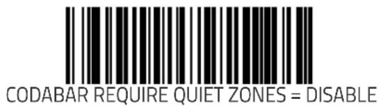

Codabar Length Control
This feature specifies whether variable-length or fixed-length decoding will be set for Codabar.
To set this feature:
- Scan the SWITCH bar code.
- Scan your selection from the bar codes below. You'll need to cover any unused bar codes on this and the facing page to ensure that the scanner reads only the bar code you intend to scan.
- Complete the programming sequence by scanning the SWITCH bar code.
You must now set the features Codabar Length 1 on page 423 and Codabar Length 2 on page 424.
NOTE
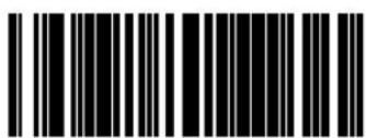
CODABAR LENGTH CONTROL = VARIABLE-LENGTH
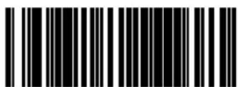
CODABAR LENGTH CONTROL = FIXED-LENGTH
Codabar Length 1
Length 1 is the minimum label length if in variable length mode, or the first fixed length if in fixed length mode (see Codabar Length Control on page 422). Length includes the barcode's check and data characters.
To set this feature:
- Scan the SWITCH bar code.
- Scan the bar code, SET CODABAR LENGTH 1 on page 423 below. You'll need to cover any unused bar codes on this and the facing page to ensure that the scanner reads only the bar code you intend to scan.
- Scan the appropriate digits from the keypad in Appendix C that represent the desired label length. The selectable range for this option is 003 to 050. Pad all single and double digit numbers with leading zeroes to yield a three-digit entry (003–050).
- Complete the programming sequence by scanning the SWITCH bar code.
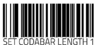
Codabar Length 2
Length 2 is the maximum label length if in variable length mode, or the second fixed length if in fixed length mode (see Codabar Length Control on page 422). Length includes the barcode's check and data characters.
To set this feature:
- Scan the SWITCH bar code.
- Scan the bar code, SET STANDARD 2 OF 5 LENGTH 2 on page 408 below. You'll need to cover any unused bar codes on this and the facing page to ensure that the scanner reads only the bar code you intend to scan.
- Scan the appropriate digits from the keypad in Appendix C that represent the desired label length. A setting of 000 will ignore this length (only one fixed length), otherwise, the selectable range for this option is 003 to 050. Pad all single and double digit numbers with leading zeroes to yield a three-digit entry (003–050).
- Complete the programming sequence by scanning the SWITCH bar code.
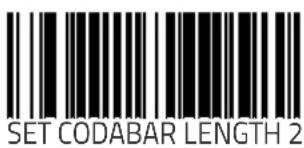
Codabar Correlation
This feature enables/disables character correlation for Codabar.
To set this feature:
- Scan the SWITCH bar code.
- Scan your selection from the bar codes below. You'll need to cover any unused bar codes on this and the facing page to ensure that the scanner reads only the bar code you intend to scan.
Complete the programming sequence by scanning the SWITCH bar code.
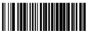
CODABAR CORRELATION = DISABLE

CODABAR CORRELATION = ENABLE
Codabar Stitching
Enables/disables stitching for Codabar labels. When parts of a Codabar bar code are presented to the scanner with this feature enabled, the bar code parts will be assembled by the scanner's software, and the data will be decoded if all bar code proofing requirements are met.
To set this feature:
- Scan the SWITCH bar code.
- Scan your selection from the bar codes below. You'll need to cover any unused bar codes on this and the facing page to ensure that the scanner reads only the bar code you intend to scan.
Complete the programming sequence by scanning the SWITCH bar code.
Codabar Stitching operates using fixed lengths ONLY. Codabar Length 1 on page 423 and/or Codabar Length 2 on page 424 must be properly configured for stitching to work.
NOTE

CODABAR STITCHING = DISABLE
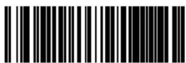
CODABAR STITCHING = ENABLE
Codabar Minimum Reads
Specifies the minimum number of consecutive times a Codabar label must be decoded before it is accepted as a good read.
To set this feature:
- Scan the SWITCH bar code.
- Scan the bar code representing the desired option below or on the following pages. You'll need to cover any unused bar codes on facing pages to ensure that the scanner reads only the bar code you intend to scan.
Complete the programming sequence by scanning the SWITCH bar code.
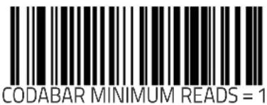

Codabar Minimum Reads (continued)
Remember to cover any unused bar codes on this and the facing page to ensure that the scanner reads only the bar code you intend to scan.

CODABAR MINIMUM READS = 3

CODABAR MINIMUM READS = 4
Code 93 Enable
Enables/disables the ability of the scanner to decode Code 93 labels.
To set this feature:
- Scan the SWITCH bar code.
- Scan either the enable or disable bar code below. You'll need to cover any unused bar codes on this and the facing page to ensure that the scanner reads only the bar code you intend to scan.
- Complete the programming sequence by scanning the SWITCH bar code.

CODE 93 = DISABLE

CODE 93 = ENABLE
Code 93 Label ID
This feature specifies a Code 93 label ID to be added to bar code data..

NOTE
The programming feature, Label ID Control, designates whether the Label ID is transmitted as a prefix or suffix or if Label ID is disabled.
To set this feature:
- Scan the SWITCH bar code.
- Scan the bar code, SET CODE 93 LABEL ID on page 430 below. You'll need to cover any unused bar codes on this and the facing page to ensure the scanner reads only the bar code you intend to scan.
-
Scan the appropriate digits from the keypad in Appendix C that represent the desired Label ID characters; entered as two hex pairs. A table containing the ASCII Character Set on page 1 and their corresponding Hex Values is available in the inside back cover of this manual. ASCII parameters must be input by scanning a pair of hexadecimal digits for each character. Thus, to set a two-character value of AB, bar codes containing the digits '4', '1', '4', and '2' must be scanned. The selectable range for this option is any hex value from 00 to FF.
-
Complete the programming sequence by scanning the SWITCH bar code.

SET CODE 93 LABEL ID
Code 93 Length Control
This feature specifies whether variable-length or fixed-length decoding will be set for Code 93.
To set this feature:
- Scan the SWITCH bar code.
- Scan your selection from the bar codes below. You'll need to cover any unused bar codes on this and the facing page to ensure that the scanner reads only the bar code you intend to scan.
- Complete the programming sequence by scanning the SWITCH bar code.
You must now set the features Code 93 Length 1 on page 432 and Code 93 Length 2 on page 433.
NOTE

CODE 93 LENGTH CONTROL = VARIABLE-LENGTH
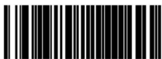
CODE 93 LENGTH CONTROL = FIXED-LENGTH
Code 93 Length 1
Length 1 is the minimum label length if in variable length mode, or the first fixed length if in fixed length mode (see Code 93 Length Control on page 431). Length includes the barcode's check and data characters.
To set this feature:
- Scan the SWITCH bar code.
- Scan the bar code, SET CODE 93 LENGTH 1 on page 432 below. You'll need to cover any unused bar codes on this and the facing page to ensure that the scanner reads only the bar code you intend to scan.
- Scan the appropriate digits from the keypad in Appendix C that represent the desired label length. The selectable range for this option is 001 to 050. Pad all single and double digit numbers with leading zeroes to yield a three-digit entry (001–050).
- Complete the programming sequence by scanning the SWITCH bar code.
Code 93 Length 2
Length 2 is the maximum label length if in variable length mode, or the second fixed length if in fixed length mode (see Code 93 Length Control on page 431). Length includes the barcode's check and data characters.
To set this feature:
- Scan the SWITCH bar code.
- Scan the bar code, SET CODE 93 LENGTH 2 on page 433 below. You'll need to cover any unused bar codes on this and the facing page to ensure that the scanner reads only the bar code you intend to scan.
- Scan the appropriate digits from the keypad in Appendix C that represent the desired label length. A setting of 000 will ignore this length (only one fixed length), otherwise, the selectable range for this option is 001 to 050. Pad all single and double digit numbers with leading zeroes to yield a three-digit entry (001–050).
- Complete the programming sequence by scanning the SWITCH bar code.
Code 93 Correlation
This feature enables/disables character correlation for Code 93.
To set this feature:
- Scan the SWITCH bar code.
- Scan your selection from the bar codes below. You'll need to cover any unused bar codes on this and the facing page to ensure that the scanner reads only the bar code you intend to scan.
Complete the programming sequence by scanning the SWITCH bar code.

CODE 93 CORRELATION = DISABLE

CODE 93 CORRELATION = ENABLE
Code 93 Stitching
Enables/disables stitching for Code 93 labels. When parts of a Code 93 bar code are presented to the scanner with this feature enabled, the bar code parts will be assembled by the scanner's software, and the data will be decoded if all bar code proofing requirements are met.
To set this feature:
- Scan the SWITCH bar code.
- Scan your selection from the bar codes below. You'll need to cover any unused bar codes on this and the facing page to ensure that the scanner reads only the bar code you intend to scan.
Complete the programming sequence by scanning the SWITCH bar code.

CODE 93 STITCHING = DISABLE

CODE 93 STITCHING = ENABLE
Code 93 Minimum Reads
Specifies the minimum number of consecutive times a Code 93 label must be decoded before it is accepted as a good read.
To set this feature:
- Scan the SWITCH bar code.
- Scan the bar code representing the desired option below or on the following pages. You'll need to cover any unused bar codes on facing pages to ensure that the scanner reads only the bar code you intend to scan.
Complete the programming sequence by scanning the SWITCH bar code.
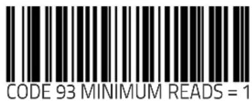
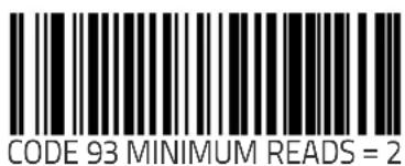
Code 93 Minimum Reads (continued)
Remember to cover any unused bar codes on this and the facing page to ensure that the scanner reads only the bar code you intend to scan.

CODE 93 MINIMUM READS = 3

CODE 93 MINIMUM READS = 4
MSI/Plessey Enable
Enables/disables the ability of the scanner to decode MSI/Plessey labels.
To set this feature:
- Scan the SWITCH bar code.
- Scan either the enable or disable bar code below. You'll need to cover any unused bar codes on this and the facing page to ensure that the scanner reads only the bar code you intend to scan.
- Complete the programming sequence by scanning the SWITCH bar code.

MSI/PLESSEY = DISABLE
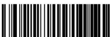
MSI/PLESSEY = ENABLE
MSI/Plessey Check Character Calculation
Enables/disables calculation and verification of optional MSI/Plessey check characters.

NOTE
If check character calculation is disabled, the risk is increased that a misread can occur. When disabled, any check characters in a bar code are treated as data characters.
To set this feature:
- Scan the SWITCH bar code.
- Scan either the enable or disable bar code below. You'll need to cover any unused bar codes on this and the facing page to ensure that the scanner reads only the bar code you intend to scan.
- Complete the programming sequence by scanning the SWITCH bar code.

MSI/PLESSEY CHECK CHARACTER CALCULATION = DISABLE

MSI/PLESSEY CHECK CHARACTER CALCULATION = ENABLE
MSI/Plessey Number of Check Characters
Specifies number of MSI/Plessey check characters to be calculated and verified.
Check characters are always modulus 10.
NOTE
To set this feature:
- Scan the SWITCH bar code.
- Scan the bar code below representing the desired number of MSI/Plessey check characters to be calculated and verified. You'll need to cover any unused bar codes on this and the facing page to ensure that the scanner reads only the bar code you intend to scan.
- Complete the programming sequence by scanning the SWITCH bar code.
MSI/PLESSEY NUMBER OF CHECK CHARACTERS = 1
MSI/PLESSEY NUMBER OF CHECK CHARACTERS = 2
MSI/Plessey Check Character Transmission
Enables/disables transmission of optional MSI/Plessey check characters.

NOTE
This feature applies only when MSI/Plessey Check Character Calculation on page 439 is enabled.
To set this feature:
- Scan the SWITCH bar code.
- Scan either the enable or disable bar code below. You'll need to cover any unused bar codes on this and the facing page to ensure that the scanner reads only the bar code you intend to scan.
- Complete the programming sequence by scanning the SWITCH bar code.

MSI/PLESSEY CHECK CHARACTER TRANSMISSION = DISABLE

MSI/PLESSEY CHECK CHARACTER TRANSMISSION = ENABLE
MSI/Plessey Label ID
This feature specifies an MSI/Plessey label ID to be added to bar code data.

NOTE
The programming feature, Label ID Control, designates whether the Label ID is transmitted as a prefix or suffix or if Label ID is disabled.
To set this feature:
- Scan the SWITCH bar code.
- Scan the bar code, SET MSI/PLESSEY LABEL ID on page 442 below. You'll need to cover any unused bar codes on this and the facing page to ensure the scanner reads only the bar code you intend to scan.
-
Scan the appropriate digits from the keypad in Appendix C that represent the desired Label ID characters; entered as two hex pairs. A table containing the ASCII Character Set on page 1 and their corresponding Hex Values is available in the inside back cover of this manual. ASCII parameters must be input by scanning a pair of hexadecimal digits for each character. Thus, to set a two-character value of AB, bar codes containing the digits '4', '1', '4', and '2' must be scanned. The selectable range for this option is any hex value from 00 to FF.
-
Complete the programming sequence by scanning the SWITCH bar code.

SET MSI/PLESSEY LABEL ID
MSI/Plessey Length Control
This feature specifies whether variable-length or fixed-length decoding will be set for MSI/Plessey.
To set this feature:
- Scan the SWITCH bar code.
- Scan your selection from the bar codes below. You'll need to cover any unused bar codes on this and the facing page to ensure that the scanner reads only the bar code you intend to scan.
- Complete the programming sequence by scanning the SWITCH bar code.

NOTE
You must now set the features MSI/Plessey Length 1 on page 444 and MSI/Plessey Length 2 on page 445.
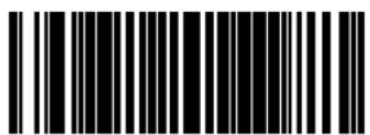
MSI/PLESSEY LENGTH CONTROL = VARIABLE-LENGTH

MSI/PLESSEY LENGTH CONTROL = FIXED-LENGTH
MSI/Plessey Length 1
Length 1 is the minimum label length if in variable length mode, or the first fixed length if in fixed length mode (see MSI/Plessey Length Control on page 443). Length includes the barcode's check and data characters.
To set this feature:
- Scan the SWITCH bar code.
- Scan the bar code, SET MSI/PLESSEY LENGTH 1 on page 444 below. You'll need to cover any unused bar codes on this and the facing page to ensure that the scanner reads only the bar code you intend to scan.
- Scan the appropriate digits from the keypad in Appendix C that represent the desired label length. The selectable range for this option is 004 to 016. Pad all single and double digit numbers with leading zeroes to yield a three-digit entry (004–016).
- Complete the programming sequence by scanning the SWITCH bar code.

SET MSI/PLESSEY LENGTH 1
MSI/Plessey Length 2
Length 2 is the maximum label length if in variable length mode, or the second fixed length if in fixed length mode (see Code 93 Length Control on page 431). Length includes the barcode's check and data characters.
To set this feature:
- Scan the SWITCH bar code.
- Scan the bar code, SET CODE 93 LENGTH 2 on page 433 below. You'll need to cover any unused bar codes on this and the facing page to ensure that the scanner reads only the bar code you intend to scan.
- Scan the appropriate digits from the keypad in Appendix C that represent the desired label length. A setting of 000 will ignore this length (only one fixed length), otherwise, the selectable range for this option is 004 to 016. Pad all single and double digit numbers with leading zeroes to yield a three-digit entry (004–016).
- Complete the programming sequence by scanning the SWITCH bar code.

MSI/Plessey Correlation
This feature enables/disables character correlation for MSI/Plessey. To set this feature:
- Scan the SWITCH bar code.
- Scan your selection from the bar codes below. You'll need to cover any unused bar codes on this and the facing page to ensure that the scanner reads only the bar code you intend to scan.
Complete the programming sequence by scanning the SWITCH bar code.
MSI/PLESSEY CORRELATION = DISABLE

MSI/PLESSEY CORRELATION = ENABLE
MSI/Plessey Stitching
Enables/disables stitching for MSI/Plessey labels. When parts of an MSI/Plessey bar code are presented to the scanner with this feature enabled, the bar code parts will be assembled by the scanner's software, and the data will be decoded if all bar code proofing requirements are met.
To set this feature:
- Scan the SWITCH bar code.
- Scan your selection from the bar codes below. You'll need to cover any unused bar codes on this and the facing page to ensure that the scanner reads only the bar code you intend to scan.
- Complete the programming sequence by scanning the SWITCH bar code.

NOTE
MSI/Plessey Stitching operates using fixed lengths ONLY. MSI/Plessey Length 1 on page 444 and/or MSI/Plessey Length 2 on page 445 must be properly configured for stitching to work.

MSI/PLESSEY STITCHING = DISABLE

MSI/PLESSEY STITCHING = ENABLE
MSI/Plessey Minimum Reads
Specifies the minimum number of consecutive times an MSI/Plessey label must be decoded before it is accepted as a good read.
To set this feature:
- Scan the SWITCH bar code.
- Scan the bar code representing the desired option below or on the following pages. You'll need to cover any unused bar codes on facing pages to ensure that the scanner reads only the bar code you intend to scan.
Complete the programming sequence by scanning the SWITCH bar code.

MSI/PLESSEY MINIMUM READS = 1
MSI/PLESSEY MINIMUM READS = 2
MSI/Plessey Minimum Reads (continued)
Remember to cover any unused bar codes on this and the facing page to ensure that the scanner reads only the bar code you intend to scan.
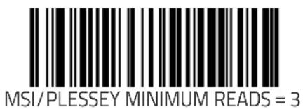

MSI/PLESSEY MINIMUM READS = 4
NOTES
Appendix A
LED/Beeper Indications & Controls
Figure 53 shows the operator's controls and indicators. The descriptions following identify the use or function of each component.
Figure 53. Scanner and Scale Controls

Controls and Indicators
The control panel consists of a green LED indicator, a Volume/Tone push button and a Scale Zero push button/LED indicator as described in the following pages. The unit also includes a beeper which can be configured to sound indications of scanning, weighing, and deactivation activities.

NOTE
Since beeper indications are configurable, your unit may not be programmed to sound all the indications listed. For more information, see Chapter 6, Programming in this manual.
LED and Beeper Indications
Scanner and Scale LEDs
The Scanner LED indicates scanner status, and the Scale LED (which is in combination with the Scale push button) is primarily used to show scale status (see Table 4).
Table 4. Scanner and Scale LED Indications
| LED INDICATION | DURATION COMMENT | |
| Scale at Zero^a | Scale (Yellow) LED on steady | The scale is at rest and reads zero weight. The scale is ready to weigh. |
| Scanner Active ^a (Normal Mode) | Scanner (Green) LED on steady and dim | The scanner is ready for operation. Scanning is immediately available. |
| Good Read Indication ^a | Scanner (Green) LED - bright flash | Indicates a bar code has been read and decoded. |
| Program Mode Indication | Scanner (Green) LED - Continuous flashing | Indicates the scanner is in Label Programming Mode. Cycle power to exit Programming Mode. |
| Sleep Mode Indication | Scanner (Green) LED flashes slowly | The scanner motor and/or laser have automatically switched off and the unit has entered Sleep Mode due to extended inactivity. |
| Host Dis-abled | Scanner (Green) LED 1-second off, 1/10-second on | Host has disabled scanning. |
| Field Replaceable Unit (FRU) Warning (Error Mode) | Audible low tone 1 second. Alternating Scanner/Scale (Green/Yellow) LEDs flash continuously. | Serves notice that a fatal FRU failure has been detected. Consult "Error Codes" on page 69 for more details. If a low tone is heard, but continuous flashing is not observed, the scanner can still function in a limited capacity. Call systems support for service in either case. |
| FRU Indication | Scanner (Green) LED flashes a coded sequence in concert with the speaker. | Occurs ONLY upon Volume/Tone button push following a FRU warning. Enables service technicians to identify FRU failures. |
a. Certain functions of the Green and Yellow LEDs are selectable to be enabled or disabled. Your scanner may not be programmed to display all indications.
Volume/Tone Push Button
The Volume/Tone Push Button also performs multiple functions depending upon the duration of time it is pressed:

NOTE
The Volume/Tone Push Button must be configured to enable standard functions, or the features described will not apply. Reference Chapter 6, Scanner Button Options for programming details.
Volume changes made using the Volume/Tone Push Button are lost when the scanner is powered-down and are reset to the factory default setting. If you wish to permanently change the volume, use the special programming labels in Chapter 6, Good Read Beep Volume.
| PRESS DURATION | FUNCTION COMMENT | |
| Momentary (when scanner is asleep) | Wakes scanner from Sleep Mode | Alternatively, the scanner can be awakened by:- Moving an object through the scan zone.- A weight change on the scale.- Scanning with an attached auxiliary scanner. |
| Momentary (when scanner is awake) | Increments volume | Press the push button momentarily to increase speaker volume. When the loudest volume is reached, a repeated press of the push button cycles volume back to the lowest setting, then volume increases on subsequent press(es). Four volume levels are available. |
| Hold, then release when the beeper sounds | Increments tone | Press the push button for approximately 2 seconds, then release. Each time this is done, the beeper will sound at one of three tones. Stop when the desired tone (high, medium or low) is sounded. |
| 4 Seconds | Scanner Diagnostics Modea | This mode allows system support personnel to troubleshoot problems with the scanner. Upon entering Scanner Diagnostic Mode, view the 7-segment display to view Interface Type, Bootloader Version Number, Application Version Number and Configuration File Number. This mode is used to determine if a scanner can read bar codes. Press the button for eight seconds or cycle power to exit Scanner Diagnostics Mode and reset the scanner. |
| 8 Seconds | Resets Scannerb | Only system support personnel should perform a reset. |
a. Diagnostics Mode is meant for use by trained systems support personnel. Users should not need to initiate this function under normal circumstances.
b. Users should not perform scanner resets except under the direction of trained systems support personnel.
Scale Zero Push Button

The Scale Zero Push Button is used for multiple functions as listed.
The Scale Zero Push Button has no function in a "scanner only" model. The button must be configured to enable standard functions, or Scale Diagnostics will not be an available feature. Reference Chapter 6, Scanner Button Options for programming details.
| PRESS DURATION | FUNCTION COMMENT | |
| Momentary Zero Scale | When programmed to do so, the yellow LED should be lit when no weight is on the scale, indicating scale at zero. If it is not, press the switch to zero the scale. | |
| 4 Seconds | Scale Diagnostics Modea | This mode allows system support personnel to troubleshoot problems with the scale. Momentarily press the Scale Zero Push Button or cycle power to exit Scale Diagnostics Mode. |
a. Diagnostics Mode is meant for use by trained systems support personnel. Users should not need to initiate this function under normal circumstances.
Calibration Switch
This switch initiates the scale's calibration routine. A certified weight set is needed to perform the scale calibration steps detailed in Chapter 5, Calibration. This switch is not included in scanners without scale modules.
Calibration Switch Seal
This seal allows you to secure the Calibration Switch access cover and restrict access to the Calibration Switch. If the calibration seal is broken or missing, you may be prohibited from operating the scale without recertification. Check local and state requirements for specific restrictions.
Calibration Switch
A cover restricts access to the Calibration Switch to help guard against unauthorized tampering when sealed. The Calibration Switch is located just beneath the Spider in the location indicated in Figure 54.
LEGAL NOTE
There are regulations that must be followed in order to ensure compliance when operating a weighing device such as the scanner/scale. Failure to observe and comply with these regulations could result in legal action.
Figure 54. Calibration Switch

NOTES

Appendix B Cable Information
Introduction
The following pages contain pinout information, enabling you to create standard interface cables for use in interconnecting the scanner, scale, external handheld scanner, and POS terminal.
General Specifications
Wire Requirements
- Cable length should not exceed 15 feet.
- Wire gauge = Standard for RJ-45 connectors (28-26 AWG).
- If run exceeds 15 feet, we recommend 26 AWG wire size.
RS-232 Cable Pinout
Scanner
Connector Hardware
RJ45, 10 Position
Cable Pinout
| PIN # FUNCTION DESCRIPTION | ||
| 1 | N/C | No Connection |
| 2 | C | T Clear To Send (input) n |
| 3 | N/C | No Connection |
| 4 | R T | Request To Send(output) u t |
| 5 | R x | Receive Data (Input) n |
| 6 | T x | Transmit Data (output) u t |
| 7 | N/C | No Connection |
| 8 | N/C | No Connection |
| 9 | GND | Signal Ground |
| 10 N/C | No Connection | |
Scale
Connector Hardware
RJ45, 10 Position
Cable Pinout
| PIN # FUNCTION DESCRIPTION | ||
| 1 +5V pullup | +5V pullup | |
| 2 C T Clear To Send (input) I | ||
| 3 N/C | No Connection | |
| 4 R T Request To Send (output) U | ||
| 5 R x Receive Data (Input) I | ||
| 6 T x Transmit Data (output) U | ||
| 7 N/C | No Connection | |
| 8 N/C | No Connection | |
| 9 Gnd | Signal Ground | |
| 10 N/C | No Connection | |
IBM Cable Pinout
Scanner and Scale
Connector Hardware
RJ45, 10 Position
Cable Pinout
| PIN # FUNCTION DESCRIPTION | ||
| 1 | N/C | No Connection |
| 2 | N/C | No Connection |
| 3 | N/C | No Connection |
| 4 | L | Linle B N |
| 5 | N/C | No Connection |
| 6 | L | Linle A N |
| 7 | N/C | No Connection |
| 8 | N/C | No Connection |
| 9 | GND | Signal Ground |
| 10 N/C | No Connection | |
OEM USB Cable Pinout
Scanner and Scale
Connector Hardware
RJ45, 10 Position
Cable Pinout
| PIN # FUNCTION DESCRIPTION | ||
| 1 | N/C | No Connection |
| 2 | N/C | No Connection |
| 3 | V | BUSB VBUS U S |
| 4 | U S | USB D- B D - |
| 5 | N/C | No Connection |
| 6 | U S | USB D+ B D + |
| 7 | N/C | No Connection |
| 8 | N/C | No Connection |
| 9 | GND | Signal Ground |
| 10 N/C | No Connection | |
Auxiliary Port
External Handheld Input
Connector Hardware
RJ45, 10 Position
Cable Pinout
| PIN # FUNCTION DESCRIPTION | ||
| 1 | + 5 | +5V pullup p u |
| 2 | C | Clear To Send (input) i n |
| 3 | N/C | No Connection - Reserved |
| 4 | R T | Request To Send (output) u |
| 5 | R x | Receive Data (Input) i n |
| 6 | T x | TransmitData (output) u |
| 7 | N/C | No Connection |
| 8 +5V out (500mA max) | +5V out | |
| 9 | GND | Signal Ground |
| 10 N/C | No Connection | |
Power Cable
Connector Hardware
3 pin Molex
Cable Pinout
| PIN # FUNCTION DESCRIPTION | ||||
| 1 EARTH GND | Earth Ground | |||
| 2 | S | I | Signal Ground | A L |
| 3 | + | 1 | +12V in 2 | V I |
Remote Display
Connector Hardware
4 pin SDL
Cable Pinout
| PIN # FUNCTION DESCRIPTION | ON | ||||
| 1 | + | 1 | +12V out | V | 0 |
| 2 | L | I | N LINE A Display | - | A |
| 3 | L | I | N LINE B Display | - | B |
| 4 | GND | Ground | |||
U
D
D
EAS Comm Port (Sensormatic® systems ONLY)
EAS Deactivator Control Box Connection
Connector Hardware
RJ4
Cable Pinout
| PIN # FUNCTION DESCRIPTION | ||
| 1 | GND | GND |
| 2 | + 5 | +5V Out V 0 u |
| 3 | External Read Indica-tor | When configured, signifies good read |
| 4 | A u | Intended to drive an external ampli-fier that drives and external o speaker. |
NOTES
Appendix C Keypad
Use the bar codes in this appendix to enter numbers and characters as you would select digits/characters from a keypad.
Scan your selection from the bar codes below. You'll need to cover any unused bar codes on this and the facing page to ensure that the scanner reads only the bar code you intend to scan.
0

1
Use the bar codes in this appendix to enter numbers and characters as you would select digits/characters from a keypad.
Scan your selection from the bar codes below. You'll need to cover any unused bar codes on this and the facing page to ensure that the scanner reads only the bar code you intend to scan.
2

3
Use the bar codes in this appendix to enter numbers and characters as you would select digits/characters from a keypad.
Scan your selection from the bar codes below. You'll need to cover any unused bar codes on this and the facing page to ensure that the scanner reads only the bar code you intend to scan.

4

5
Use the bar codes in this appendix to enter numbers and characters as you would select digits/characters from a keypad.
Scan your selection from the bar codes below. You'll need to cover any unused bar codes on this and the facing page to ensure that the scanner reads only the bar code you intend to scan.
6
7
Use the bar codes in this appendix to enter numbers and characters as you would select digits/characters from a keypad.
Scan your selection from the bar codes below. You'll need to cover any unused bar codes on this and the facing page to ensure that the scanner reads only the bar code you intend to scan.

8

9
Use the bar codes in this appendix to enter numbers and characters as you would select digits/characters from a keypad.
Scan your selection from the bar codes below. You'll need to cover any unused bar codes on this and the facing page to ensure that the scanner reads only the bar code you intend to scan.

A

B
Use the bar codes in this appendix to enter numbers and characters as you would select digits/characters from a keypad.
Scan your selection from the bar codes below. You'll need to cover any unused bar codes on this and the facing page to ensure that the scanner reads only the bar code you intend to scan.

C

D
Use the bar codes in this appendix to enter numbers and characters as you would select digits/characters from a keypad.
Scan your selection from the bar codes below. You'll need to cover any unused bar codes on this and the facing page to ensure that the scanner reads only the bar code you intend to scan.
E

F
Appendix D
Host Commands
Accepting Commands from an RS-232 Scanner Host
The scanner responds to the following RS-232 commands:
COMMAND ASCII HEX COMMENT
| Enable Scanner | E | 0 | x | 4 | 5 |
| Disable Scanner | D | 0 | x | 4 | 4 |
| Reset Scanner | R | 0 | x | 5 | 2 |
| Not On File Indication | F 0x46 Long series of beeps | ||||
| Beep Good Read Tone | B 0x42 Beeps if Good Read Beep is enabled | ||||
| Force Good Read Tone | 0x01 Beeps regardless of beep setting | ||||
| Bel | 0x07 Force Good Read Tone | ||||
| Identification request | i | 0 | x | 6 | Returns long responsea |
| Health request | h | 0 | x | 6 | Returns long responsea |
| Status request | s | 0 | x | 7 | Returns long responsea |
a. Call Tech Support for information.
If one of the above commands is received, the scanner will perform the steps indicated for the command. Host commands for other interfaces is also available. Contact Tech Support for more details.
NOTES
Appendix E
Keyboard Function Key Mappings
Keyboard Model Cross Reference
Table summarizes the keyboard models, their defined protocol, scancode set, and some unique features. The remaining tables in this chapter provide the function key maps associated with each of the scancode sets.
Table 5. Keyboard Model Cross Reference
| Model Type I/F ID | Transmission Protocol | Scancode Set | Function Key Map Support | Use Country Mode | |
| PC/XT Foreign ALT Mode | Wedge A | PC/XT | Scan Set 1 No | No | |
| AT;PS/2 25-286;PS/2 30-286;PS/2 50, 50Z;PS/2 60,70,80,90,95 Foreign ALT Mode | Wedge B | AT/PS2 | Scan Set 2 No | No | |
| PS/2 25 and 30 Foreign ALT Mode | Wedge C | AT/PS2 | Scan Set 1 No | No | |
| PC/XT U.S. Mode | Wedge D | PC/XT | Scan Set 1 Yes | No | |
| AT;PS/2 25-286;PS/2 30-286;PS/2 50, 50Z;PS/2 60,70,80,90,95 U.S. Mode + specific country support | Wedge E | AT/PS2 | Scan Set 2 Yes | Yes | |
| PS/2 25 and 30 U.S. Mode | Wedge F | AT/PS2 | Scan Set 1 Yes | No | |
| IBM 3xxx Terminals (122-key keyboard) | Wedge G | AT/PS2 | Scan Set 3 Yes | No | |
| IBM 3xxx Terminals (102-key keyboard) | Wedge H | AT/PS2 | Scan Set 3 Yes | No | |
| PS55 5530T with JAPANESE DOS (TDOS) | Wedge I | AT/PS2 | Japanese DOS | Yes No | |
| NEC 9801 | Wedge J | NEC 9801 | NEC 9801 Yes | No |
Table 6. Scanset 1 Function Key Map
| ASCII (hex) | ASCII code | Key Scancode | |
| 00 NUL | ALT right Make E0h 38h | ||
| 01 SOH | ALT right Break E0h B8h | ||
| 02 STX | ALT left Make 38h | ||
| 03 ETX | ALT left Break B8h | ||
| 04 EOT | CTRL left Make 1Dh | ||
| 05 ENQ | CTRL left Break 9Dh | ||
| 06 ACK | CTRL right Make E0h 1Dh | ||
| 07 BEL | CTRL right Break E0h 9Dh | ||
| 08 | BS | BS | 0Eh |
| 09 | HT | TAB right | 0Fh |
| 0A | LF | RIGHT arrow (inner keypad) | 4Dh + E0 |
| 0B | VT | TAB left | 0Fh + S |
| 0C | FF | Enter (inner keypad) | 1Ch + E0 |
| 0D | CR | CR | 1Ch |
| 0E | SO | INSERT (inner keypad) | 52h + E0 |
| 0F | SI | PAGE UP (inner keypad) | 49h + E0 |
| 10 DLE | PAGE DOWN (inner keypad) | 51h + E0 | |
| 11 DC1 | HOME (inner keypad) | 47h + E0 | |
| 12 DC2 | LEFT arrow (inner keypad) | 4Bh + E0 | |
| 13 DC3 | DOWN arrow (inner keypad) | 50h + E0 | |
| 14 DC4 | UP arrow (inner keypad) | 48h + E0 |
Table 7. Scanset 2 Function Key Map
| ASCII (hex) | ASCII code | Key Scancode | |
| 00 NUL | ALT right Make E0h 11h | ||
| 01 SOH | ALT right Break E0h F0h 11h | ||
| 02 STX | ALT left Make 11h | ||
| 03 ETX | ALT left Break F0h 11h | ||
| 04 EOT | CTRL left Make 14h | ||
| 05 ENQ | CTRL left Break F0h 14h | ||
| 06 ACK | CTRL right Make E0h 14h | ||
| 07 BEL | CTRL right Break E0h F0h 14h | ||
| 08 BS | BS 66h | ||
| 09 HT | TAB right | 0Dh | |
| 0A LF | RIGHT arrow (inner keypad) | 74h + E0 | |
| 0B VT | TAB left | 0Dh + S | |
| 0C | FF | Enter (right keypad) 5Ah + E0 | |
| 0D | CR | CR 5Ah | |
| 0E | SO | INSERT (inner keypad) | 70h + E0 |
| 0F | SI | PAGE UP (inner keypad) | 7Dh + E0 |
| 10 DLE | PAGE DOWN (inner keypad) | 7Ah + E0 | |
| 11 DC1 | HOME (inner keypad) | 6Ch + E0 | |
| 12 DC2 | LEFT arrow (inner keypad) | 6Bh + E0 | |
| 13 DC3 | DOWN arrow (inner keypad) | 72h + E0 | |
| 14 DC4 | UP arrow (inner keypad) | 75h + E0 | |
| 15 NAK | F6 | 0Bh | |
| 16 | SYN | F1 | 05h |
| 17 ETB | F2 | 06h | |
| 18 CAN | F3 | 04h | |
| 19 | EM | F4 | 0Ch |
| 1A SUB | F5 | 03h | |
| 1B ESC | ESC | 76h | |
| 1C | FS | F7 | 83h |
| 1D | GS | F8 | 0Ah |
| 1E RS | F9 | 01h | |
| 1F US | F10 | 09h |
Table 8. Scanset 3, 102-Key Function Key Map
| ASCII (hex) | ASCII code | Key Scancode | |
| 00 NUL | ALT right Make 39h | ||
| 01 SOH | ALT right Break F0h 39h | ||
| 02 STX | ALT left Make 19h | ||
| 03 ETX | ALT left Break F0h 19h | ||
| 04 EOT | CTRL left Make 11h | ||
| 05 ENQ | CTRL left Break F0h 11h | ||
| 06 ACK | CTRL right Make 58h | ||
| 07 BEL | CTRL right Break F0h 58h | ||
| 08 BS | BS | 66h | |
| 09 HT | TAB right | 0Dh | |
| 0A LF | RIGHT arrow (inner keypad) | 6Ah | |
| 0B VT | TAB left | 0Dh + S | |
| 0C | FF | Enter (inner keypad) | 79h |
| 0D | CR | CR | 5Ah |
| 0E | SO | INSERT (inner keypad) | 67h |
| 0F | SI | PAGE UP (inner keypad) | 6Fh |
| 10 DLE | PAGE DOWN (inner keypad) | 6Dh | |
| 11 DC1 | HOME (inner keypad) | 6Eh | |
| 12 DC2 | LEFT arrow (inner keypad) | 61h | |
| 13 DC3 | DOWN arrow (inner keypad) | 60h | |
| 14 DC4 | UP arrow (inner keypad) | 63h | |
| 15 NAK | F6 | 2Fh | |
| 16 | SYN | F1 | 07h |
| 17 ETB | F2 | 0Fh | |
| 18 CAN | F3 | 17h | |
| 19 | EM | F4 | 1Fh |
| 1A SUB | F5 | 27h | |
| 1B ESC | ESC | 08h | |
| 1C | FS | F7 | 37h |
| 1D | GS | F8 | 3Fh |
| 1E RS | F9 | 47h | |
| 1F US | F10 | 4Fh |
Table 9. Scanset 3 122-Key Function Key Map
| ASCII (hex) | ASCII code | Key Scancode | |
| 00 NUL | ALT Right Make 39h | ||
| 01 SOH | ALT Right Break F0h 39h | ||
| 02 STX | ALT left Make 19h | ||
| 03 ETX | ALT left Break F0h 19h | ||
| 04 EOT | CTRL left (RESET) Make only 11h | ||
| 05 ENQ | CTRL left (RESET) Make/Break | 11h F0h 11h | |
| 06 ACK | ONLINE Enter Make only 58h | ||
| 07 BEL | ONLINE Enter Make/Break 58h | F0h 58h | |
| 08 | BS | BS | 66h |
| 09 | HT | TAB right | 0Dh |
| 0A | LF | RIGHT arrow (inner keypad) | 6Ah |
| 0B | VT | TAB left | 0Dh + S |
| 0C | FF | CR (FIELD EXIT) Make only | 5Ah F0h 5Ah |
| 0D | CR | CR (FIELD EXIT) Make/Break | 5Ah |
| 0E | SO | INSERT (inner keypad) 65h | |
| 0F | SI | FIELD + | 79h |
| 10 DLE | FIELD - | 7Ch | |
| 11 DC1 | HOME (inner keypad) | 62h | |
| 12 DC2 | LEFT arrow (inner keypad) | 61h | |
| 13 DC3 | DOWN arrow (inner keypad) | 60h | |
| 14 DC4 | UP arrow (inner keypad) | 63h | |
| 15 NAK | F6 | 2Fh | |
| 16 | SYN | F1 | 07h |
| 17 ETB | F2 | 0Fh | |
| 18 CAN | F3 | 17h | |
| 19 | EM | F4 | 1Fh |
| 1A SUB | F5 | 27h | |
| 1B | ESC | ESC | 08h |
| 1C | FS | F7 | 37h |
| 1D | GS | F8 | 3Fh |
| 1E | RS | F9 | 47h |
| 1F | US | F10 | 4Fh |
Table 10. Japanese DOS Function Key Map
| ASCII value | ASCII code Key | Scancode | |
| 00h NUL | ALT right Make | 31h | |
| 01h SOH | ALT right Break | B1h | |
| 02h STX | ALT left Make | 31h | |
| 03h ETX | ALT left Break | B1h | |
| 04h EOT | CTRL left Make | 41h | |
| 05h ENQ | CTRL left Break | C1h | |
| 06h ACK | CTRL right Make | 41h | |
| 07h BEL | CTRL right Break | C1h | |
| 08h BS | BS | 3Eh | |
| 09h HT | TAB right | 3Ch | |
| 0Ah LF | RIGHT arrow (inner key-pad) | 4Dh | |
| 0Bh VT | TAB left | 3Ch + S | |
| 0Ch FF | Enter (right keypad) | 60h | |
| 0Dh CR | CR | 3Bh | |
| 0Eh SO | INSERT (inner keypad) | 52h | |
| 0Fh SI | PAGE UP (inner keypad) | 49h | |
| 10h DLE | PAGE DOWN (inner keypad) | 51h | |
| 11h DC1 | HOME (inner keypad) | 4Ch | |
| 12h DC2 | LEFT arrow (inner keypad) | 4Bh | |
| 13h DC3 | DOWN arrow (inner keypad) | 4Ah | |
| 14h DC4 | UP arrow (inner keypad) | 4Eh | |
| 15h NAK | F6 | 6Dh | |
| 16h SYN | F1 | 68h | |
| 17h ETB | F2 | 69h | |
| 18h CAN | F3 | 6Ah | |
| 19h EM | F4 | 6Bh | |
| 1Ah SUB | F5 | 6Ch | |
| 1Bh ESC | ESC | 3Dh | |
| 1Ch FS | F7 | 6Eh | |
| 1Dh GS | F8 | 6Fh | |
| 1Eh RS | F9 | 70h | |
| 1Fh US | F10 | 71h |
Table 11. NEC 9801-Key Function Key Map
| ASCII value | ASCII code Key | Scancode | |
| 00h NUL | unused | n/a | |
| 01h SOH | CR | 1Ch | |
| 02h STX | CAPS LOCK ON (make) | 71h | |
| 03h ETX | CAPS LOCK OFF (break) | F1h | |
| 04h EOT | CTRL left Make | 74h | |
| 05h ENQ | CTRL left Break | F4h | |
| 06h ACK | CTRL-C | 60h | |
| 07h BEL | n/a | n/a | |
| 08h BS | BS | 0Eh | |
| 09h HT | TAB right | 0Fh | |
| 0Ah LF | RIGHT arrow (inner key-pad) | 3Ch | |
| 0Bh VT | TAB left | 0Fh + S | |
| 0Ch FF | DELETE | 39h | |
| 0Dh CR | CR | 1Ch | |
| 0Eh SO | INSERT (inner keypad) | 38h | |
| 0Fh SI | KATAKANA LOCK ON (Make) | 72h | |
| 10h DLE | KATAKANA LOCK OFF (Break) | F2h | |
| 11h DC1 | HOME (inner keypad) | 3Eh | |
| 12h DC2 | LEFT arrow (inner keypad) | 3Bh | |
| 13h DC3 | DOWN arrow (inner keypad) | 3Dh | |
| 14h DC4 | UP arrow (inner keypad) | 3Ah | |
| 15h NAK | F6 | 67h | |
| 16h SYN | F1 | 62h | |
| 17h ETB | F2 | 63h | |
| 18h CAN | F3 | 64h | |
| 19h EM | F4 | 65h | |
| 1Ah SUB | F5 | 66h | |
| 1Bh ESC | ESC | 00h | |
| 1Ch FS | F7 | 68h | |
| 1Dh GS | F8 | 69h | |
| 1Eh RS | F9 | 6Ah | |
| 1Fh US | F10 | 6Bh |
Table 12. USB Keyboard Function Key Usage Map
| ASCII Key | Value Usage | Name |
| 00 NUL | ALT right Make | |
| 01 SOH | ALT right Break | |
| 02 STX | F11 | |
| 03 ETX | F12 | |
| 04 EOT | GUI right Make | |
| 05 ENQ | GUI right Break | |
| 06 ACK | CTRL right Make | |
| 07 BEL | CTRL right Break | |
| 08 BS | BS | |
| 09 HT | TAB right | |
| 0A LF | RIGHT arrow (inner keypad) | |
| 0B VT | TAB left | |
| 0C FF | Enter (right keypad) | |
| 0D CR | CR | |
| 0E SO | INSERT (inner keypad) | |
| 0F SI | PAGE UP (inner keypad) | |
| 10 DLE | PAGE DOWN (inner keypad) | |
| 11 DC1 | HOME (inner keypad) | |
| 12 DC2 | LEFT arrow (inner keypad) | |
| 13 DC3 | DOWN arrow (inner keypad) | |
| 14 DC4 | UP arrow (inner keypad) | |
| 15 NAK | F6 | |
| 16 SYN | F1 | |
| 17 ETB | F2 | |
| 18 CAN | F3 | |
| 19 EM | F4 | |
| 1A SUB | F5 | |
| 1B ESC | ESC | |
| 1C FS | F7 | |
| 1D GS | F8 | |
| 1E RS | F9 | |
| 1F US | F10 |
NOTES
Appendix F
Factory Defaults
The following table provides a listing of the most common factory settings for the interfaces shown.
Table 13. Factory Default Settings
| RS-232 | Wincor-Nixdorf | RS-232 Single Cable | Keybd. Wedge | IBM | OEM USB | |
| Scanner Button Options on page 106 | Enable Std Functions | Enable Std Functions | Enable Std Functions | Enable Std Functions | Enable Std Functions | Enable Std Functions |
| Double Read Time-out on page 108 | 400ms 400ms 400ms 400ms 400ms | |||||
| Laser Timeout on page 110 | 5 min. 5 min. 5 min. 5 min. 5 min. | |||||
| Motor Timeout on page 112 | 10 min. 10 min. 10 min. 10 min. 10 min. | |||||
| Label Gone Time-out on page 115 | 160 msec 160 msec 160 msec 160 msec 160 msec | 160 msec | ||||
| Auxiliary Port Mode on page 118 | Disable | Enable Handheld | Disable Disable | Disable | ||
| Auxiliary Port Baud Rate on page 120 | 19200 19200 19200 19200 19200 | |||||
| Laser Failure Mode on page 124 | Single OK Single OK Single OK Single OK Single OK | Single OK Single OK Single OK Single OK Single OK Single OK Single OK Single OK Single OK Single OK Single OK Single OK Single OK Single OK Single OK Single OK Single OK Single OK Single OK Single OK Single OK Single OK Single OK Single OK Single OK Single OK Single OK Single OK Single OK Single OK Single OK Single OK Single OK Single OK Single OK Single OK Single OK Single OK Single OK Single OK Single OK Single OK Single OK Single OK Single OK Single OK Single OK Single OK Single OK Single OK Single OK | ||||
| Productivity Index Reporting (PIR)/ Cashier Training (CT) on page 125 | Disable Disable | Disable Disable | Disable | |||
| Green LED Idle State on page 126 | On dim On | dim On dim | On dim On dim | On dim | ||
| Power-up Beep Control on page 127 | 1 beep 1 | beep 1 beep 1 | beep 1 beep 1 | beep | ||
| Good Read Beep Control on page 128 | Enable Enable Enable Enable Enable | |||||
| Good Read Beep Frequency on page 129 | Medium Medium Medium Medium Medium | |||||
| Good Read Beep Length on page 131 | 80ms 80ms 80ms 80ms 80ms | |||||
| Good Read Beep Volume on page 132 | High High High High High High | |||||
| Good Read When to Indicate on page 135 | After decode | After decode | After decode | After decode | After decode | After decode |
| Scale Enable on page 137 | Enable Enable Enable Enable | |||||
| Scale Enforced Zero Return on page 138 | 3 (non-zero for 4 minutes) | 3 (non-zero for 4 minutes) | Disable | 3 (non-zero for 4 minutes) | 3 (non-zero for 4 minutes) | |
| Scale Interface Type on page 141 | RS-232 SASI | RS-232 SASI | ||||
| Scale Calibration Notification on page 143 | Disable Disable | Disable Disable | ||||
| Scale Intercharacter Delay on page 144 | No delay No delay | |||||
| Remote Display — Enable/Disable on page 145 | Enable Enable Enable Enable Enable | |||||
| EAS Active State on page 146 | Low Low Low Low Low | |||||
| EAS Timeout on page 147 | 20ms 20ms 20ms 20ms 20ms | |||||
| Maximum Host-Transmitted Message Length on page 168 | No limit No limit No limit No limit No limit | |||||
| Number of Host Transmission Buffers on page 169 | 2 buffers 1 buffer 2 buffers 2 buffers 1 buffer 1 buffer | |||||
| AIM ID on page 170 | Disable Disable Disable | |||||
| Label ID Control on page 172 | Enable as prefix | Enable as prefix | Enable as prefix | Enable as prefix | ||
| Global Prefix on page 175 | 00 (""') 00 (""') 00 (""') 00 (""') | |||||
| Global Suffix on page 177 | OD00 () | OD00 () | 00 ("" ) | OD00 () | ||
| Case Conversion on page 179 | No conversion | No conversion | No conversion | No conversion | No conversion | No conversion |
| IBM Interface Options on page 181 | 10 (custom options) | Full Host Interface Support | Full Host Interface Support | |||
| IBM Number of Host Resets on page 182 | 6 | 6 | ||||
| IBM Scale Address on page 183 | 6E 6E | |||||
| IBM Transmit Labels in Code 39 Format on page 185 | Disable Disable | |||||
| IBM Label Slicing Control on page 186 | Slice when nec. | Slice when nec. | ||||
| IBM Maximum Label Slice Length on page 187 | 64 64 | |||||
| OEM USB Scanner Device Type on page 188 | Table top scanner | |||||
| RS-232 Baud Rate on page 189 | 9600 9600 | 9600 | ||||
| RS-232 Number of Data Bits on page 193 | 8 data bits | 8 data bits | 7 data bits | |||
| RS-232 Number of Stop Bits on page 194 | 1 stop bit 1 | stop bit 1 stop bit | ||||
| RS-232 Parity on page 195 | None Odd | Odd | ||||
| RS-232 Hardware Control on page 197 | Disable | Enable CTS flow | ||||
| RS-232 Intercharacter Delay on page 200 | None None | |||||
| RS-232 Software Flow Control on page 201 | Disable Disable Disable | |||||
| RS-232 Host Echo on page 202 | Disable Disable | |||||
| RS-232 Host Echo Quiet Interval on page 203 | 10ms 10ms | |||||
| RS-232 Ignore Host Commands on page 204 | Do not ignore | Do not ignore | Do not ignore | Do not ignore | Do not ignore | Do not ignore |
| RS-232 TTL on page 205 | Normal RS-232 | Normal RS-232 | ||||
| RS-232 TTL Invert on page 206 | No invert No invert | |||||
| RS-232 ICL DC1 Character Delay Enable on page 207 | Disable Disable | |||||
| RS-232 Team POS ICL Scale on page 208 | Disable Disable | |||||
| RS-232 Beep on ASCII BEL on page 209 | Disable Disable | |||||
| RS-232 Beep After Weigh on page 210 | Disable Disable Disable | |||||
| RS-232 Beep on Not on File on page 211 | Enable Enable Enable | |||||
| RS-232 ACK NAK Enable on page 212 | Disable Disable | |||||
| RS-232 ACK Character on page 214 | ACK ACK | |||||
| RS-232 NAK Character on page 215 | NAK NAK | |||||
| RS-232 Retry on ACK NAK Timeout on page 216 | Enable Enable | |||||
| RS-232 ACK NAK Timeout Value on page 217 | 200ms 200ms | |||||
| RS-232 ACK NAK Retry Count on page 218 | 3 resets 3 resets | |||||
| RS-232 ACK NAK Error Handling on page 219 | Ignore errors | Ignore errors | ||||
| Single Cable RS-232 Scanner Only Protocol on page 223 | Scanner-scale | |||||
| Single Cable RS-232 Stale Weight Timeout on page 224 | 330 msec | |||||
| Single Cable RS-232 Scale — Transmit Weight Digits on page 226 | Transmit as 4 digits | |||||
| Single Cable Manufacturer Extensions on page 227 | Disable | |||||
| Single Cable Pace-setter Plus Enable on page 228 | Disable | |||||
| Single Cable RS-232 RTS CTSSelection on page 229 | Option 5 | |||||
| Single Cable RS-232 Use BCC on page 232 | Disable | |||||
| Single Cable RS-232 Use ACK/NAK on page 233 | Disable | |||||
| Single Cable RS-232 Use STX on page 234 | Enable | |||||
| Set Single Cable RS-232 STX Character on page 235 | S | |||||
| Set Single Cable RS-232 ETX Character on page 236 | Enable | |||||
| Set Single Cable RS-232 ETX Character on page 236 | CR | |||||
| Keyboard Interface — Keyboard Lay-out on page 237 | US | |||||
| Keyboard Interface Quiet Interval on page 246 | 100 ms | |||||
| Keyboard Interface Caps Lock State on page 247 | Caps lock OFF | |||||
| Keyboard Interface — Keyboard Simulation on page 249 | Disable | |||||
| Keyboard Interface — Control Characters on page 250 | Disable | |||||
| Keyboard Interface — Intercharacter Delay on page 252 | 10 msec | |||||
| Coupon Control on page 253 | Disable Disable Enable Enable Enable Enable Enable Enable Enable Enable Enable Enable Enable Enable Enable Enable Enable Enable Enable Enable Enable Enable Enable Enable Enable Enable Enable Enable Enable Enable Enable Enable Enable Enable Enable Enable Enable Enable Enable Enable Enable Enable Enable Enable Enable Enable Enable Enable Enable Enable Enable Enable Enable Enable Enable Enable Enable Enable Enable Enable Enable Enable Enable Enable Enable Enable Enable Enable Enable Enable Enable Enable Enable Enable Enable Enable Enable Enable Enable Enable Enable Enable Enable Enable Enable Enable Enable Enable Enable Enable Enable Enable Enable Enable Enable Enable Enable Enable Enable Enable Enable Enable enable Enable Enable Enable Enable Enable Enable Enable Enable Enable Enable Enable Enable Enable Enable Enable Enable Enable Enable Enable Enable Enable Enable Enable Enable Enable Enable Enable Enable Enable Enable Enable Enable Enable Enable Enable Enable Enable Enable Enable Enable Enable Enable Enable Enable Enable Enable Enable Enable Enable Enable Enable Enable Enable Enable Enable Enable Enable Enable Enable Enable Enable Enable Enable Enable Enable Enable Enable Enable Enable Enable Enable Enable Enable Enable Enable Enable Enable Enable Enable Enable Enable Enable Enable Enable Enable Enable Enable Enable Enable Enable Enable Enable Enable Enable Enable Enable Enable Enable Enableible Enable Enable Enable Enable Enable Enable Enable Enable Enable Enable Enable Enable Enable Enable Enable Enable Enable Enable Enable Enable Enable Enable Enable Enable Enable Enable Enable Enable Enable Enable Enable Enable Enable Enable Enable Enable Enable Enable Enable Enable Enable Enable Enable Enable Enable Enable Enable Enable Enable Enable Enable Enable Enable Enable Enable Enable Enable Enable Enable Enable Enable Enable Enable Enable Enable Enable Enable Enable Enable Enable Enable Enable Enable Enable Enable Enable Enable Enable Enable Enable Enable Enable Enable Enable Enable Enable Enable Enable Enable Enable Enable Enable Enable Enable Enable Enable Enable Enable EnableEnable Enable Enable Enable Enable Enable Enable Enable Enable Enable Enable Enable Enable Enable Enable Enable Enable Enable Enable Enable Enable Enable Enable Enable Enable Enable Enable Enable Enable Enable Enable Enable Enable Enable Enable Enable Enable Enable Enable Enable Enable Enable Enable Enable Enable Enable Enable Enable Enable Enable Enable Enable Enable Enable Enable Enable Enable Enable Enable Enable Enable Enable Enable Enable Enable Enable Enable Enable Enable Enable Enable Enable Enable Enable Enable Enable Enable Enable Enable Enable Enable Enable Enable Enable Enable Enable Enable Enable Enable Enable Enable Enable Enable Enable Enable Enable Enable Enable Enable Enable才能是 | |||||
| UPC-A Enable on page 255 | Enable Enable Enable Enable Enable Enable Enable Enable Enable Enable Enable Enable Enable Enable Enable Enable Enable Enable Enable Enable Enable Enable Enable Enable Enable Enable Enable Enable Enable Enable Enable Enable Enable Enable Enable Enable Enable Enable Enable Enable Enable Enable Enable Enable Enable Enable Enable Enable Enable Enable Enable Enable Enable Enable Enable Enable Enable Enable Enable Enable Enable Enable Enable Enable Enable Enable Enable Enable Enable Enable Enable Enable Enable Enable Enable Enable Enable Enable Enable Enable Enable Enable Enable Enable Enable Enable Enable Enable Enable Enable Enable Enable Enable Enable Enable Enable Enable Enable Enable enable enable enable enable enable enable enable enable enable enable enable enable enable enable enable enable enable enable enable enable enable enable enable enable enable enable enable enable enable enable enable enable enable enable enable enable enable enable enable enable enable enable enable enable enable enable enable enable enable enable enable enable enable enable enable enable enable enable enable enable enable enable enable enable enable enable enable enable enable enable enable enable enable enable enable enable enable enable enable enable enable enable enable enable enable enable enable enable enable enable enable enable enable enable enable enable enable enable enable enable只能是 | |||||
| UPC-A Number System Character Transmission on page 256 | Enable Enable Enable Enable Enable Enable Enable Enable Enable Enable Enable Enable Enable Enable Enable Enable Enable Enable Enable Enable Enable Enable Enable Enable Enable Enable Enable Enable Enable Enable Enable Enable Enable Enable Enable Enable Enable Enable Enable Enable Enable Enable Enable Enable Enable Enable Enable Enable Enable Enable Enable Enable Enable Enable Enable Enable Enable Enable Enable enable enable enable enable enable enable enable enable enable enable enable enable enable enable enable enable enable enable enable enable enable enable enable enable enable enable enable enable enable enable enable enable enable enable enable enable enable enable enable enable enable只能是 | |||||
| UPC-A Check Character Trans-mission on page 257 | Enable Enable Disable Enable Enable Enable Enable Enable Enable Enable Enable Enable Enable Enable Enable Enable Enable Enable Enable Enable Enable Enable Enable Enable Enable Enable Enable Enable Enable Enable Enable Enable Enable Enable Enable Enable Enable Enable Enable Enable Enable Enable Enable Enable Enable Enable Enable Enable Enable Enable Enable Enable Enable Enable Enable Enable Enable Enable Enable Enable Enable Enable Enable Enable Enable Enable Enable Enable enable enable enable enable enable enable enable enable enable enable enable enable enable enable enable enable enable enable enable enable enable enable enable enable enable enable enable enable enable enable enable enable enable enable只能是 | |||||
| Expand UPC-A to EAN-13 on page 258 | Disable Enable Disable Disable Disable Disable Disable Disable Disable Disable Disable Disable Disable Disable Disable Disable Disable Disable Disable Disable Disable Disable Disable Disable Disable Disable Disable Disable Disable Disable Disable Disable Disable Disable Disable Disable Disable Disable Disable Disable Disable Disable Disable Disable Disable Disable Disable Disable Disable Disable Disable Disable Disable Disable Disable Disable Disable Disable Disable Disable Disable Disable Disable Disable Disable Disable Disable Disable Disable Disable Disable Disable Disable Disable Disable Disable Disable Disable Disable Disable Disable Disable Disable Disable Disable Disable Disable Disable Disable Disable Disable Disable Disable Disable Disable Disable Disable Disable Disable Disable Disable Disable disable enable enable enable enable enable enable enable enable enable enable enable enable enable enable enable enable enable enable enable enable enable enable enable enable enable enable enable enable enable enable enable enable enable enable enable enable enable enable enable enable enable enable enable enable enable enable enable enable enable enable enable enable enable enable enable enable enable enable enable enable enable enable enable enable enable enable enable enable enable enable enable enable enable enable enable enable enable enable enable enable enable enable enable enable enable enable enable enable enable enable enable enable enable enable enable enable enable enable enable incentive只能是 | |||||
| UPC-A Label ID on page 259 | A | A | A | A | ||
| UPC-A 2-Digit Supplemental Label ID on page 260 | A | A | A | A | ||
| UPC-A 5-Digit Supplemental Label ID on page 261 | A | A | A | A | ||
| UPC-A 128 Supplemental Label ID on page 262 | A | A | A | A | ||
| UPC-A Minimum Reads on page 263 | 1 | 1 | 1 | 1 | 1 | 1 |
| UPC-E Enable on page 265 | Enable Enable Enable Enable Enable Enable | |||||
| UPC-E Number System Character Transmission on page 266 | Enable Enable Enable Enable Enable Enable | |||||
| UPC-E Check Character Transmission on page 267 | Disable Disable Disable Disable Enable Enable | |||||
| Expand UPC-E to UPC-A on page 268 | Disable Disable Disable Disable Disable Disable | |||||
| Expand UPC-E to EAN-13 on page 269 | Disable Disable Disable Disable Disable Disable | |||||
| UPC-E Label ID on page 270 | E | C | E | E | ||
| UPC-E 2-Digit Supplemental Label ID on page 271 | E | C | E | E | ||
| UPC-E 5-Digit Supplemental Label ID on page 272 | E | C | E | E | ||
| UPC-E 128 Sup-plemental Label ID on page 273 | E | C | E | E | ||
| UPC-E Minimum Reads on page 274 | 2 | 2 | 2 | 2 | 2 | 2 |
| EAN-13 Enable on page 276 | Enable Enable Enable Enable Enable | |||||
| EAN-13 First Character Trans-mission on page 277 | Enable Enable Enable Enable Enable | |||||
| EAN-13 Check Character Trans-mission on page 278 | Enable Enable Disable Enable Enable Enable | |||||
| EAN-13 ISBN Con-version Enable on page 279 | Disable Disable Disable Disable Disable | |||||
| EAN 13 Label ID on page 280 | F | A | F | F | ||
| EAN-13 2-Digit Supplemental Label ID on page 281 | F | A | F | F | ||
| EAN-13 5-Digit Supplemental Label ID on page 282 | F | A | F | F | ||
| EAN-13 Minimum Reads on page 284 | 1 | 1 | 1 | 1 | 1 | 1 |
| EAN-13 128 Supplemental Label ID on page 283 | F | A | F | F | ||
| Bookland Label ID on page 286 | I | A | I | I | ||
| EAN-8 Enable on page 287 | Enable Enable Enable Enable Enable | |||||
| EAN-8 Check Character Transmission on page 288 | Enable Enable Disable Enable Enable Enable | |||||
| Expand EAN-8 to EAN-13 on page 289 | Disable Disable Disable Disable Disable | |||||
| EAN-8/JAN-8 Guard Insertion on page 290 | Disable Disable Disable Disable Disable Disable | |||||
| EAN-8/JAN-8 Guard Substitution on page 291 | Enable Enable Enable Enable Enable Enable | |||||
| EAN-8/JAN-8 Both Guards Substitution on page 292 | Disable Disable Disable Disable Disable Disable | |||||
| EAN-8 Stitch Exact Label Halves on page 293 | Disable Disable | Disable Disable | Disable Disable | Disable | ||
| EAN-8 Stitch Unlike Label Halves on page 294 | Disable Disable | Disable Disable | Disable Disable | Disable | ||
| EAN 8 Label ID on page 295 | FF B FF | FF | ||||
| EAN-8 2-Digit Supplemental Label ID on page 296 | FF B FF | FF | ||||
| EAN-8 5-Digit Supplemental Label ID on page 297 | FF B FF | FF | ||||
| EAN-8 128 Sup-plemental Label ID on page 298 | FF B FF | FF | ||||
| EAN-8 Decoding Levels on page 299 | 1 (Very Conservative) | 1 (Very Conservative) | 1 (Very Conservative) | 1 (Very Conservative) | 1 (Very Conservative) | 1 (Very Conservative) |
| EAN-8 Minimum Reads on page 302 | 2 | 1 | 2 | 2 | 2 | 2 |
| EAN-8 Minimum Segment Length on page 304 | 8 | 8 | 8 | 8 | 8 | 8 |
| Price Weight Check on page 311 | Disable Disable | Disable | Disable Disable | Disable | ||
| In-Store Label Minimum Reads on page 314 | 2 | 2 | 2 | 2 | 2 | 2 |
| Enable EAN Two Label on page 316 | Disable Disable | Disable | Disable Disable | Disable | ||
| EAN Two Label Combined Transmission on page 317 | Disable Disable | Disable | Disable Disable | Disable | ||
| UPC/EAN Guard Insertion on page 318 | Disable Disable | Disable | Disable Disable | Disable | ||
| UPC/EAN Stitch Exact Label Halves on page 319 | Disable Disable | Disable | Disable Disable | Disable | ||
| UPC/EAN Stitch Unlike Label Halves on page 320 | Disable Disable | Disable | Disable Disable | Disable | ||
| UPC/EAN Character Reconstruction on page 321 | Disable Disable | Disable | Disable Disable | Disable | ||
| EAN Two Label Minimum Reads on page 322 | 1 | 1 | 1 | 1 | 1 | 1 |
| Addon Timer on page 335 | 70mS 70mS | 70mS 70mS | 70mS 70mS | 70mS 70mS | ||
| UPC/EAN Correlation on page 324 | Disable | Disable | Disable | Disable | ||
| 2-Digit Add-ons Minimum Reads on page 336 | 2 | 2 | 2 | 2 | 2 | 2 |
| 5-Digit Add-ons Minimum Reads on page 338 | 1 | 1 | 1 | 1 | 1 | 1 |
| Code 128 Add-ons Minimum Reads on page 340 | 1 | 1 | 1 | 1 | 1 | 1 |
| UPC/EAN Minimum Segment Length on page 325 | 5 | 5 | 5 | 5 | 5 | 5 |
| GTIN Enable on page 342 | Disable | Disable | Disable | Disable | ||
| GTIN Label ID on page 343 | G | G | G | G | ||
| GTIN 2-Digit Supplemental Label ID on page 344 | G2 G2 G2 G2 | |||||
| GTIN 5-Digit Supplemental Label ID on page 345 | G5 G5 G5 G5 | |||||
| GTIN Code 128 Supplemental Label ID on page 346 | G8 G8 G8 G8 | |||||
| DataBar Omnidi-rectional Enable on page 347 | Disable | Disable | Disable | Disable | ||
| DataBar Omnidi-rectional/EAN-128 Emulation on page 348 | Disable | Disable | Disable | Disable | ||
| DataBar Omnidi-rectional Label ID on page 349 | R4 E R4 | R4 | ||||
| DataBar Omnidi-rectional Mini-mum Reads on page 350 | 1 | 1 | 1 | 1 | 1 | 1 |
| DataBar Expanded Enable on page 352 | Disable | Disable | Disable | Disable | ||
| DataBar Expanded EAN-128 Emula-tion on page 353 | Disable | Disable | Disable | Disable | ||
| DataBar Expanded Label ID on page 354 | RX E RX | RX | ||||
| DataBar Expanded Length Control on page 355 | Variable | Variable | Variable | Variable | ||
| DataBar Expanded Length 1 on page 356 | 1 | 1 | 1 | 1 | 1 | 1 |
| DataBar Expanded Length 2 on page 357 | 74 74 74 | 74 74 74 | ||||
| DataBar Expanded Minimum Reads on page 358 | 1 | 1 | 1 | 1 | 1 | 1 |
| Code 39 Enable on page 360 | Enable Disable Enable Enable Enable Enable | |||||
| Code 39 Start Stop Character Transmission on page 361 | Disable Disable Disable Disable Disable | |||||
| Code 39 Check Character Calculation on page 362 | Disable Disable Disable Disable Disable | |||||
| Code 39 Check Character Transmission on page 363 | Enable Enable Enable Enable Enable Enable | |||||
| Code 39 Full ASCII on page 364 | Disable Disable Disable Disable Disable | |||||
| Code 39 Label ID on page 365 | * | M | B | 1 | * | |
| Code 39 Require Quiet Zones on page 366 | Disable Disable Disable Disable Disable Disable | |||||
| Code 39 Length Control on page 367 | Variable Variable Variable Variable Variable Variable | |||||
| Code 39 Length 1 on page 368 | 2 | 2 | 2 | 2 | 2 | 2 |
| Code 39 Length 2 on page 369 | 50 50 50 | 50 50 50 | ||||
| Code 39 Correlation on page 370 | Disable Disable Enable Enable Enable Enable Enable Enable Enable Enable Enable Enable Enable Enable Enable Enable Enable Enable Enable Enable Enable Enable Enable Enable Enable Enable Enable Enable Enable Enable Enable Enable Enable Enable Enable Enable Enable Enable Enable Enable Enable Enable Enable Enable Enable Enable Enable Enable Enable Enable Enable Enable Enable Enable Enable Enable Enable Enable Enable Enable Enable Enable Enable Enable Enable Enable Enable Enable Enable Enable Enable Enable Enable Enable Enable Enable Enable Enable Enable Enable Enable Enable Enable Enable Enable Enable Enable Enable Enable Enable Enable Enable Enable Enable Enable Enable Enable Enable Enable Enable Enable Enable enable Enable Enable Enable Enable Enable Enable Enable Enable Enable Enable Enable Enable Enable Enable Enable Enable Enable Enable Enable Enable Enable Enable Enable Enable Enable Enable Enable Enable Enable Enable Enable Enable Enable Enable Enable Enable Enable Enable Enable Enable Enable Enable Enable Enable Enable Enable Enable Enable Enable Enable Enable Enable Enable Enable Enable Enable Enable Enable Enable Enable Enable Enable Enable Enable Enable Enable Enable Enable Enable Enable Enable Enable Enable Enable Enable Enable Enable Enable Enable Enable Enable Enable Enable Enable Enable Enable Enable Enable Enable Enable Enable Enable Enable Enable Enable Enable Enable Enable EnableEnable Enable Enable Enable Enable Enable Enable Enable Enable Enable Enable Enable Enable Enable Enable Enable Enable Enable Enable Enable Enable Enable Enable Enable Enable Enable Enable Enable Enable Enable Enable Enable Enable Enable Enable Enable Enable Enable Enable Enable Enable Enable Enable Enable Enable Enable Enable Enable Enable Enable Enable Enable Enable Enable Enable Enable Enable Enable Enable Enable Enable Enable Enable Enable Enable Enable Enable Enable Enable Enable Enable Enable Enable Enable Enable Enable Enable Enable Enable Enable Enable Enable Enable Enable Enable Enable Enable Enable Enable Enable Enable Enable Enable Enable Enable Enable Enable Enable Enable Enableible Enable Enable Enable Enable Enable Enable Enable Enable Enable Enable Enable Enable Enable Enable Enable Enable Enable Enable Enable Enable Enable Enable Enable Enable Enable Enable Enable Enable Enable Enable Enable Enable Enable Enable Enable Enable Enable Enable Enable Enable Enable Enable Enable Enable Enable Enable Enable Enable Enable Enable Enable Enable Enable Enable Enable Enable Enable Enable Enable Enable Enable Enable Enable Enable Enable Enable Enable Enable Enable Enable Enable Enable Enable Enable Enable Enable Enable Enable Enable Enable Enable Enable Enable Enable Enable Enable Enable Enable Enable Enable Enable Enable Enable Enable Enable Enable Enable Enable Enable只能是无效,可以是无效,可以是无效,可以是无效,可以是无效,可以是无效,可以是无效,可以是无效,可以是无效,可以是无效,可以是无效,可以是无效,可以是无效,可以是无效,可以是无效,可以是无效,可以是无效,可以是无效,可以是无效,可以是无效,可以是无效,可以是无效,可以是无效,可以是无效,可以是无效,可以是无效,可是无效,可以是无效,可以是无效,可以是无效,可以是无效,可以是无效,可以是无效,可以是无效,可以是无效,可以是无效,可以是无效,可以是无效,可以是无效,可以是无效,可以是无效,可以是无效,可以是无效,可以是无效,可以是无效,可以是无效,可以是无效,可以是无效,可以是无效,可以是无效,可以是无效,不能是无效,可以是无效,可以是无效,可以是无效,可以是无效,可以是无效,可以是无效,可以是无效,可以是无效,可以是无效,可以是无效,可以是无效,可以是无效,可以是无效,可以是无效,可以是无效,可以是无效,可以是无效,可以是无效,可以是无效,可以是无效,可以是无效,可以是无效,可以是无效,可以是无效,三者有效,可以是无效,可以是无效,可以是无效,可以是无效,可以是无效,可以是无效,可以是无效,可以是无效,可以是无效,可以是无效,可以是无效,可以是无效,可以是无效,可以是无效,可以是无效,可以是无效,可以是无效,可以是无效,可以是无效,可以是无效,可以是无效,可以是无效,可以是无效,可以是无效,可以是失效,可以是无效,可以是无效,可以是无效,可以是无效,可以是无效,可以是无效,可以是无效,可以是无效,可以是无效,可以是无效,可以是无效,可以是无效,可以是无效,可以是无效,可以是无效,可以是无效,可以是无效,可以是无效,可以是无效,可以是无效,可以是无效,可以是无效,可以是无效,可以是无效,可以是无,可以是无效,可以是无效,可以是无效,可以是无效,可以是无效,可以是无效,可以是无效,可以是无效,可以是无效,可以是无效,可以是无效,可以是无效,可以是无效,可以是无效,可以是无效,可以是无效,可以是无效,可以是无效,可以是无效,可以是无效,可以是无效,可以是无效,可以是无效,可以是无效,可以是無,可以是无效,可以是无效,可以是无效,可以是无效,可以是无效,可以是无效,可以是无效,可以是无效,可以是无效,可以是无效,可以是无效,可以是无效,可以是无效,可以是无效,可以是无效,可以是无效,可以是无效,可以是无效,可以是无效,可以是无效,可以是无效,可以是无效,可以是无效,可以是无效,可以是效,可以是无效,可以是无效,可以是无效,可以是无效,可以是无效,可以是无效,可以是无效,可以是无效,可以是无效,可以是无效,可以是无效,可以是无效,可以是无效,可以是无效,可以是无效,可以是无效,可以是无效,可以是无效,可以是无效,可以是无效,可以是无效,可以是无效,可以是无效,可以是无效,可以是有效,可以是无效,可以是无效,可以是无效,可以是无效,可以是无效,可以是无效,可以是无效,可以是无效,可以是无效,可以是无效,可以是无效,可以是无效,可以是无效,可以是无效,可以是无效,可以是无效,可以是无效,可以是无效,可以是无效,可以是无效,可以是无效,可以是无效,可以是无效,可以是无效,可以 是无效,可以是无效,可以是无效,可以是无效,可以是无效,可以是无效,可以是无效,可以是无效,可以是无效,可以是无效,可以是无效,可以是无效,可以是无效,可以是无效,可以是无效,可以是无效,可以是无效,可以是无效,可以是无效,可以是无效,可以是无效,可以是无效,可以是无效,可以是无效,可以是无效,可以 是有效,可以是无效,可以是无效,可以是无效,可以是无效,可以是无效,可以是无效,可以是无效,可以是无效,可以是无效,可以是无效,可以是无效,可以是无效,可以是无效,可以是无效,可以是无效,可以是无效,可以是无效,可以是无效,可以是无效,可以是无效,可以是无效,可以是无效,可以是无效,可以是无效,可以有无效,可以有无效,可以有无效,可以有无效,可以有无效,可以有无效,可以有无效,可以有无效,可以有无效,可以有无效,可以有无效,可以有无效,可以有无效,可以有无效,可以有无效,可以有无效,可以有无效,可以有无效,可以有无效,可以有无效,可以有无效,可以有无效,可以有无效,可以有无效,可以有无效,可以有限无效,可以有无效,可以有无效,可以有无效,可以有无效,可以有无效,可以有无效,可以有无效,可以有无效,可以有无效,可以有无效,可以有无效,可以有无效,可以有无效,可以有无效,可以有无效,可以有无效,可以有无效,可以有无效,可以有无效,可以有无效,可以有无效,可以有无效,可以有无效,可以有无效,可以 有无效,可以有无效,可以有无效,可以有无效,可以有无效,可以有无效,可以有无效,可以有无效,可以有无效,可以有无效,可以有无效,可以有无效,可以有无效,可以有无效,可以有无效,可以有无效,可以有无效,可以有无效,可以有无效,可以有无效,可以有无效,可以有无效,可以有无效,可以有无效,可以有无效, 可能是无效,可以有无效,可以有无效,可以有无效,可以有无效,可以有无效,可以有无效,可以有无效,可以有无效,可以有无效,可以有无效,可以有无效,可以有无效,可以有无效,可以有无效,可以有无效,可以有无效,可以有无效,可以有无效,可以有无效,可以有无效,可以有无效,可以有无效,可以有无效,可以有无效, 司能是无效,可以有无效,可以有无效,可以有无效,可以有无效,可以有无效,可以有无效,可以有无效,可以有无效,可以有无效,可以有无效,可以有无效,可以有无效,可以有无效,可以有无效,可以有无效,可以有无效,可以有无效,可以有无效,可以有无效,可以有无效,可以有无效,可以有无效,可以有无效, 司能是无效(以有效表示为有效表示为准),可以是无效(以有效表示为准),可以是无效(以有效表示为准),可以是无效(以有效表示为准),可以是无效(以有效表示为准),可以是无效(以有效表示为准),可以是无效(以有效表示为准),可以是无效(以有效表示为准),可以是无效(以有效表示为准),可以是无效(以有效表示为准),可以是无效(以有效表示为准),可以是无效(以有效表示为准),可以是无效(以有限表示为准),可以是无效(以有限表示为准),可以是无效(以有限表示为准),可以是无效(以有限表示为准),可以是无效(以有限表示为准),可以是无效(以有限表示为准),可以是无效(以有限表示为准),可以是无效(以有限表示为准),可以是无效(以有限表示为准),可以是无效(以有限表示为准),可以是无效(以有限表示为准),可以是无效(以有限表 本章或本章) | |||||
| Code 128 Transmit Function Characters on page 379 | Disable Disable | Disable Disable | Disable Disable | Disable | ||
| Convert Code 128 to Code 39 on page 380 | Disable Disable | Disable Disable | Disable Disable | Disable | ||
| Code 128 Label ID on page 381 | # | K | B | 3 | # | |
| Code 128 Length Control on page 382 | Variable Variable Variable | Variable Variable Variable | ||||
| Code 128 Length 1 on page 383 | 1 | 1 | 1 | 1 | 1 | 1 |
| Code 128 Length 2 on page 384 | 80 80 80 | 80 80 80 | ||||
| Code 128 Correlation on page 385 | Disable Disable Disable | Disable Disable Disable | ||||
| Code 128 Stitching on page 386 | Disable Disable Disable | Disable Disable Disable | ||||
| Code 128 Minimum Reads on page 387 | 1 | 1 | 1 | 1 | 1 | 1 |
| EAN-128 Enable on page 389 | Disable Disable Disable | Disable Disable Disable | ||||
| EAN-128 Label ID on page 390 | None P None None | |||||
| Interleaved 2 of 5 (1 2 of 5) Enable on page 391 | Disable Disable | Disable Disable | Disable Disable | Disable | ||
| 1 2 of 5 Check Character Calculation on page 392 | Disable Disable | Disable Disable | Disable Disable | Disable | ||
| 1 2 of 5 Check Character Transmission on page 393 | Enable Enable | Enable Enable | Enable Enable | Enable | ||
| 1 2 of 5 Label ID on page 394 | i | I | B | 2 | i | |
| 1 2 of 5 Length Control on page 395 | Variable Variable | Variable Variable | Variable Variable | |||
| 1 2 of 5 Length 1 on page 396 | 6 | 6 | 6 | 6 | 6 | 6 |
| 1 2 of 5 Length 2 on page 397 | 50 50 50 | 50 50 50 | ||||
| 1 2 of 5 Correlation on page 398 | Disable Disable | Disable Disable | Disable Disable | Disable | ||
| 1 2 of 5 Stitching on page 399 | Disable Disable | Disable Disable | Disable Disable | Disable | ||
| 1 2 of 5 Minimum Reads on page 400 | 1 | 1 | 1 | 1 | 1 | 1 |
| Standard 2 of 5 (Std 2 of 5) Enable on page 402 | Disable Disable | Disable Disable | Disable Disable | Disable | ||
| Standard 2 of 5 Check Character Calculation on page 403 | Disable Disable | Disable Disable | Disable Disable | Disable | ||
| Standard 2 of 5 Check Character Transmission on page 404 | Enable Enable | Enable Enable | Enable Enable | Enable | ||
| Standard 2 of 5 Label ID on page 405 | S | H | S | S | ||
| Standard 2 of 5 Length Control on page 406 | Variable Variable Variable | Variable Variable Variable | ||||
| Standard 2 of 5 Length 1 on page 407 | 8 | 8 | 8 | 8 | 8 | 8 |
| Standard 2 of 5 Length 2 on page 408 | 50 50 50 50 50 50 | |||||
| Standard 2 of 5 Correlation on page 409 | Disable Disable Disable | Disable Disable Disable | ||||
| Standard 2 of 5 Stitching on page 410 | Disable Disable Disable | Disable Disable Disable | ||||
| Standard 2 of 5 Minimum Reads on page 411 | 1 | 1 | 1 | 1 | 1 | 1 |
| Codabar Enable on page 413 | Disable Disable | Disable Disable | Disable Disable | Disable | ||
| Codabar Start Stop Character Transmission on page 414 | Disable Enable | Disable Disable | Disable Disable | Disable | ||
| Codabar Start Stop Character Set on page 415 | abcd/abcd | abcd/abcd | abcd/abcd | abcd/abcd | abcd/abcd | abcd/abcd |
| Codabar Start Stop Character Match on page 417 | Disable Disable | Disable Disable | Disable Disable | Disable | ||
| Codabar Check Character Calculation on page 418 | Disable Disable | Disable Disable | Disable Disable | Disable | ||
| Codabar Check Character Transmission on page 419 | Enable Enable | Enable Enable | Enable Enable | Enable | ||
| Codabar Label ID on page 420 | % | N | % | % | ||
| Codabar Require Quiet Zones on page 421 | Enable Enable | Enable Enable | Enable Enable | Enable | ||
| Codabar Length Control on page 422 | Variable Variable | Variable Variable | Variable Variable | Variable | ||
| Codabar Length 1 on page 423 | 3 | 3 | 3 | 3 | 3 | 3 |
| Codabar Length 2 on page 424 | 50 50 50 | 50 50 50 | ||||
| Codabar Correlation on page 425 | Disable Disable | Disable Disable | Disable Disable | Disable | ||
| Codabar Stitching on page 426 | Disable Disable | Disable Disable | Disable Disable | Disable | ||
| Codabar Mini-mum Reads on page 427 | 1 | 1 | 1 | 1 | 1 | 1 |
| Code 93 Enable on page 429 | Disable Disable | Disable Disable | Disable Disable | Disable | ||
| Code 93 Label ID on page 430 | & | L | & | & | ||
| Code 93 Length Control on page 431 | Variable Variable Variable | Variable Variable | ||||
| Code 93 Length 1 on page 432 | 1 | 1 | 1 | 1 | 1 | 1 |
| Code 93 Length 2 on page 433 | 50 50 50 | 50 50 50 | ||||
| Code 93 Correlation on page 434 | Disable Disable | Disable Disable | ||||
| Code 93 Stitching on page 435 | Enable Enable Enable | Enable Enable | ||||
| Code 93 Mini-mum Reads on page 436 | 1 | 1 | 1 | 1 | 1 | 1 |
| MSI/Plessey Enable on page 438 | Disable | Disable | Disable | |||
| MSI/Plessey Check Character Calculation on page 439 | Enable | Enable | Enable | |||
| MSI/Plessey Number of Check Characters on page 440 | 1 check char | 1 check char | 1 check char | 1 check char | ||
| MSI/Plessey Check Character Transmission on page 441 | Enable | Enable | Enable | |||
| MSI/Plessey Label ID on page 442 | @ | 0 | @ | @ | ||
| MSI/Plessey Length Control on page 443 | Variable | Variable | Variable | |||
| MSI/Plessey Length 1 on page 444 | 4 | 4 | 4 | 4 | ||
| MSI/Plessey Length 2 on page 445 | 16 16 16 16 | |||||
| MSI/Plessey Correlation on page 446 | Disable | Disable | Disable | |||
| MSI/Plessey Stitching on page 447 | Disable | Disable | Disable | |||
| MSI/Plessey Minimum Reads on page 448 | 1 | 1 | 1 | 1 | ||
NOTES

Appendix G
Handheld Data Format Requirements
This appendix provides application notes to describe the general format of data that can be accepted by the scanner through the auxiliary port as transmitted from a handheld scanner.
Handheld Data Format Requirements General
- 9600 bps, 8 data bits, 1 stop bit, no parity.
- RTS is used to "bracket" the data received from the handheld: RTS must be asserted high during data transmission, and deasserted after label transmission is complete. No other flow control mechanisms are required or supported. The deassertion of the RTS signal must occur no later than 50 milliseconds from the complete transmission of the last character of the transmitted data.
- The time between character transmission can be no longer than 50 milliseconds.
- Symbologies requiring fixed lengths (UPC/EAN) will enforce length requirements for validation of the label.
- Handheld scanner will be required to transmit start and stop characters for Codabar and Code 39 labels.
- Appropriate industrial length requirements will be enforced (if configured) for validation of the label.
- Maximum label lengths will be enforced for label validation (i.e. labels longer than the maximum label size will not be validated).
- Standard Datalogic formats generally use a single prefix character. The specific formats are provided below.
Datalogic Handheld Data Format Requirements
The following sections describe label transmission formats that are typically observed in factory configurations of Datalogic handheld scanners.
DataBar Omnidirectional
- Prefix must be ASCII characters 'R4'
- Check character must be included in label
- Application identifier "01" must follow the prefix and precede the base label
- Label length excluding prefix characters must be 16 characters.
• Example: 'R40101044123456789'
DataBar Expanded
- Prefix must be ASCII characters 'R4'
- Check character must be included in label
UPC-A
- System number must be included in label data.
- Check digit must be included in label data and is assumed to be correct.
- Prefix must be an ASCII character 'A' – total length including prefix must be 13.
• Example: 'A060992011187'.
UPC-A with 2-Digit Supplemental
- System number must be included in label data.
- Check digit must be included in label data and is assumed to be correct.
- Supplemental data is appended to base label.
- Prefix must be an ASCII character 'A' – total length including prefix must be 15.
• Example: 'A06099201118712'.
UPC-A with 5-Digit Supplemental
- System number must be included in label data
- Check digit must be included in label data and is assumed to be correct
- Prefix must be an ASCII character 'A' – total length including prefix must be 18
• Example: 'A06099201118712345'
UPC-A with Code 128 Supplemental
- System number must be included in label data.
- Check digit must be included in label data and is assumed to be correct.
- Supplemental data is appended to base label.
- Prefix must be an ASCII character 'A' – total length including prefix must be greater or equal to 19 Code 128 Supplemental codes are variable length having a minimum of 2 data characters).
- Characters immediately following base label must be of the form '8100', '8101' or '8102'.
• Example: 'A0609920111878100000951'.
UPC-E
- System number must be included in label data
- Check digit must be included in label data and is assumed to be correct
- Prefix must be an ASCII character 'E' – total length including prefix must be 9
• Example: 'E09988750'
UPC-E with 2-Digit Supplemental
- System number must be included in label data.
- Check digit must be included in label data and is assumed to be correct.
- Supplemental data is appended to base label.
- Prefix must be an ASCII character 'E' – total length including prefix must be 11.
• Example: 'E0998875012'.
UPC-E with 5-Digit Supplemental
- System number must be included in label data.
- Check digit must be included in label data and is assumed to be correct.
- Prefix must be an ASCII character 'E' – total length including prefix must be 14.
• Example: 'E0998875012345'.
UPC-E with Code 128 Supplemental
- System number must be included in label data.
- Check digit must be included in label data and is assumed to be correct.
- Supplemental data is appended to base label.
- Prefix must be an ASCII character 'E' – total length including prefix must be greater or equal to 15 (code 128 Supplemental codes are variable length having a minimum of 2 data characters).
- Characters immediately following base label must be of the form '8100', '8101' or '8102'.
• Example: 'E099887508101000951'.
EAN-8
- Check digit must be included in label data and is assumed to be correct
- Prefix must be an ASCII characters 'FF' – total length including prefix must be 10
• Example: 'FF00210126'
EAN-8 with 2-Digit Supplemental
- Check digit must be included in label data and is assumed to be correct.
- Supplemental data is appended to base label.
- Prefix must be an ASCII characters 'FF' – total length including prefix must be 12.
• Example: 'FF0021012612'.
EAN-8 with 5-Digit Supplemental
- Check digit must be included in label data and is assumed to be correct.
- Prefix must be an ASCII characters 'FF' – total length including prefix must be 15.
• Example: 'FF0021012612345'.
EAN-8 with Code 128 Supplemental
- Check digit must be included in label data and is assumed to be correct.
- Supplemental data is appended to base label.
- Prefix must be an ASCII characters 'FF' – total length including prefix must be greater than 16 (code 128 Supplemental codes are variable length having a minimum of 2 data characters).
- Characters immediately following base label must be of the form '8100', '8101' or '8102'.
• Example: 'FF002101268102000951'.
EAN-13
- Check digit must be included in label data and is assumed to be correct
- Prefix must be an ASCII character 'F'– total length including prefix must be 14
• Example: 'F1101234567891'
EAN-13 with 2-Digit Supplemental
- Check digit must be included in label data and is assumed to be correct
• Supplemental data is appended to base label - Prefix must be an ASCII character 'F'– total length including prefix must be 16
• Example: 'F110123456789112'
EAN-13 with 5-Digit Supplemental
- Check digit must be included in label data and is assumed to be correct.
- Prefix must be an ASCII character 'F'– total length including prefix must be 19.
• Example: 'F110123456789112345'.
EAN-13 with Code 128 Supplemental
- Check digit must be included in label data and is assumed to be correct
- Supplemental data is appended to base label
- Prefix must be an ASCII character 'F'– total length including prefix must be greater or equal to 20 (code 128 Supplemental codes are variable length having a minimum of 2 data characters)
- Characters immediately following base label must be of the form '8100', '8101' or '8102'
• Example: 'F11012345678918100000951'
Code 39
- Check character must be included in label data.
- Label length including start, stop and check characters and excluding prefix character must meet requirements imposed by the main scanner's fixed or variable label length control for this symbology type.
- Start and stop characters "*" must be included in label.
- Prefix must be an ASCII character '*'
• Example : '**Code 39.TEST*'.
Code 39-Pharmacode
- Check character must be included in label data.
- Label length including start, stop and check characters and excluding prefix character must meet requirements imposed by the main scanner's fixed or variable label length control for this symbology type.
- Start and stop characters "*" must be included in label.
- Prefix must be an ASCII character 'p'.
• Example: 'p*123456789*'.
12 of 5
- Check character must be included in label data.
- Label length including check characters and excluding prefix character must meet requirements imposed by the main scanner's fixed or variable label length control for this symbology type.
- Prefix must be an ASCII character 'i'.
• Example: 'i0123456789'.
Standard 2 of 5
- Check character must be included in label data.
- Label length including check characters and excluding prefix characters must meet requirements imposed by the main scanner's fixed or variable label length control for this symbology type.
- Prefix must be an ASCII character 's'.
• Example: 's0123456789'.
Codabar
- Check character must be included in label data.
- Label length including check character and excluding prefix character must meet requirements imposed by the main scanner's fixed or variable label length control for this symbology type.
- Prefix must be an ASCII character '%'.
- Start stop character sets must meet the matching requirement set forth by the scanner configuration item Codabar Start Stop Character Match.
- Start stop character sets must be of the form ABCD/ABCD and must be included in the label.
• Example: '%s\$99.95s' (the lower case 's' at each end of the example is a placeholder for the start stop character set).
Code 128
- Prefix must be an ASCII character '#'.
- Label length excluding prefix character must meet requirements imposed by the main scanner's fixed or variable label length control for this symbology type.
- Function characters may be transmitted as a hexadecimal value 8x. Where x correlates to function characters 1 thru 4 as follows:
- x80 = function code 1
- x81 = function code 2
- x82 = function code 3
• x83 = function code 4 - For Code 128 programming labels the format is of the general form '#/82nnnnn/r' - /82 is hexadecimal 82 and /r is carriage return.
• Example: '#Code_128.Test'.
MSI/Plessey
- Check character must be included in label data.
- Label length including check character and excluding prefix character must meet requirements imposed by the main scanner's fixed or variable label length control for this symbology type.
- Prefix must be an ASCII character '@'.
• Example: '@144769254'.
Code 93
- Prefix must be an ASCII character '&'.
- Label length excluding prefix character must meet requirements imposed by the main scanner's fixed or variable label length control for this symbology type.
• Example: '&Code93-test'.
AIM Formats
AIM specifies a 3-character string that is attached as a prefix to the label data for transmission. Because AIM specifies one identifier for UPC-A, UPC-E and EAN-13 labels, UPC-A, UPC-E and EAN-13 will be received from the handheld and transmitted to the POS by the scanner as EAN-13. Using this form of identification, the ''] character must be the first character in the label received from the handheld. Further identification of the label is specified in the section below. The AIM identifiers on the received label may or may not be transmitted to the POS and are controlled according to the data formatting settings of the scanner.
The following sections describe the prefix strings and identify what specific label characteristics can be supported.
If a label does not have one of the AIM identifiers specified below and the first three characters of the label data fit the following qualifications:
- the first character is a ']'
- the second character is a capital letter or a small letter
• the third character is a digit
...then the label is transmitted to the host with the AIM identifier still appended to the beginning of the label data.
UPC-A
- AIM does not specify UPC-A as a separate symbology using this transmission format – labels will be transmitted as EAN-13.
• Example: 'E00060992011187'.
UPC-E
- AIM does not specify UPC-E as a separate symbology using this transmission format – labels will be transmitted as EAN-13.
• Example: 'E00000000998875'.
EAN-13
- Check digit must be included in label data and is assumed to be correct.
- Prefix must be ASCII characters 'E0'– total length including prefix must be 16.
• Example: 'E01101234567891'.
EAN-8
- Check digit must be included in label data and is assumed to be correct.
- Prefix must be ASCII characters 'E4' – total length including prefix must be 11.
• Example: 'E400210126'.
2-Digit Supplemental
- Supplemental data is appended to any EAN base label.
- Prefix must be ASCII characters 'E1'.
- length of Supplemental data including prefix must be 5. Total required length is 21 for EAN-13 and 16 for EAN-8.
- Prefix for the main body portion of the label for UPCA/UPCE/EAN13 can be ]E0 or ]E3.
- If the main body prefix for UPCA/UPCE/EAN13 is ]E0, then the 2-digit addon portion of the label must have a prefix of ]E1.
Examples: addon portion is highlighted data is underlined.
| UPC-A 2-Digit addon | 'E00060992011187]E112' |
| UPC-E 2-Digit addon | 'E00000000998875]E112' |
| EAN-8 2-Digit addon | 'E400210126]E112' |
| EAN-13 2-Digit addon | 'E01101234567891]E112' |
| UPC-A ]E3006099201 | 118712 |
| UPC-E ]E3000000099 | 887512 |
| EAN-13 ]E311012345 | 6789112 |
5-Digit Supplemental
• Supplemental data is appended to any EAN base label.
- Prefix must be ASCII characters 'E2'.
- Length of supplemental data including prefix must be 8. Total required length is 24 for EAN-13 and 19 for EAN-8.
- Prefix for the main body portion of the label for UPCA/UPCE/EAN13 can be ]E0 or ]E3.
- If the main body prefix for UPCA/UPCE/EAN13 is ]E0, then the 5-digit addon portion of the label must have a prefix of ]E2.
Examples: addon portion is highlighted data is underlined.
| UPC-A 5-Digit addon | 'E00060992011187]E212345' |
| UPC-E 5-Digit addon | 'E00000000998875]E212345' |
| EAN-8 5-Digit addon | 'E400210126]E212345' |
| EAN-13 5-Digit addon | 'E01101234567891]E212345' |
| UPC-A ]E3006099201 | 118712345 |
| UPC-E ]E3000000099 | 887512345 |
| EAN-13 ]E311012345 | 6789112345 |
Code 39
- Check character must be included in label data.
- Label length including start, stop and check characters and excluding prefix characters must meet requirements imposed by the main scanner's fixed or variable label length control for this symbology type.
- Start and stop characters "*" must be included in label.
- Prefix must be ASCII characters 'A0' or 'A1'.
• Example: '*]A0Code 39.TEST*'.
Codabar
- Check character must be included in label data.
- Label length including check character and excluding prefix characters must meet requirements imposed by the main scanner's fixed or variable label length control for this symbology type.
- Prefix must be ASCII characters 'F0'.
- Start stop character sets must meet the matching requirement set forth by the scanner configuration item Codabar Start Stop Character Match.
- Start stop character sets s must be of the form ABCD/ABCD and must be included in the label.
• Example: 'F0s\$99.95s' (the lower case 's' at each end of the example is a placeholder for the start stop character set).
MSI/Plessey
- Check character must be included in label data.
- Label length including check character and excluding prefix characters must meet requirements imposed by the main scanner's fixed or variable label length control for this symbology type.
- Prefix must be ASCII characters ']M0'.
• Example: 'M0144769254'.
Code 93
- Prefix must be ASCII characters 'G0'.
- Label length excluding prefix characters must meet requirements imposed by the main scanner's fixed or variable label length control for this symbology type.
• Example : 'G0Code93-test'.
DataBar Omnidirectional
- Prefix must be ASCII characters 'e0'.
- Check character must be included in label.
- Label length excluding prefix characters must be 14 characters.
• Example: 'e001044123456789'.
DataBar Expanded
- Prefix must be ASCII characters 'e0'.
- Label length excluding prefix characters must be at least 1 character. Maximum length is the maximum label size supported by the scanner.
• Example: 'e001900123456789083103001750'.
12 of 5
- Check character must be included in label data.
- Label length including check characters and excluding prefix characters must meet requirements imposed by the main scanner's fixed or variable label length control for this symbology type.
- Prefix must be ASCII characters 'I0', 'I1' or 'I2' (other prefixes specify different check character properties which are not supported).
• Example: 'I10123456789'.
Standard 2 of 5
- Check character must be included in label data.
- Label length including check characters and excluding prefix characters must meet requirements imposed by the main scanner's fixed or variable label length control for this symbology type.
- Prefix must be an ASCII character 'JS0' (other prefixes specify different check character properties which are not supported).
• Example: 'S00123456789'.
Code 128 / EAN128
- Prefix must be either ASCII characters 'C0', 'C1' or 'C2'.
- Label length excluding prefix character must meet requirements imposed by the main scanner's fixed or variable label length control for this symbology type.
- If EAN-128 Symbology is Enabled and prefix is 'C1', label will be identified as an EAN128 otherwise it is identified as a Code 128.
- A prefix of 'C0' designates that no function code is present in the 1st or 2nd character position.
- A prefix of 'JC2' designates that a function code 1 is present in the 2nd character.
• Example : ']C0Code_128.Test'.
NOTES
ASCII Character Set
The table on this page shows ASCII characters and their corresponding Hex Values. The Hex Values in this table are needed for setting symbology-specific label identifiers, as well as enabling custom prefix and suffix characters.
| ASCII Char. | Hex No. | ASCII Char. | Hex No. | ASCII Char. | Hex No. | ASCII Char. | Hex No. |
| NUL | 00 | SP | 20 | @ | 40 | ' | 60 |
| SOH | 01 | ! | 21 | A | 41 | a | 61 |
| STX | 02 | ' | 22 | B | 42 | b | 62 |
| ETX | 03 | # | 23 | C | 43 | c | 63 |
| EOT | 04 | $ | 24 | D | 44 | d | 64 |
| ENQ | 05 | % | 25 | E | 45 | e | 65 |
| ACK | 06 | & | 26 | F | 46 | f | 66 |
| BEL | 07 | ' | 27 | G | 47 | g | 67 |
| BS | 08 | ( | 28 | H | 48 | h | 68 |
| HT | 09 | ) | 29 | I | 49 | i | 69 |
| LF | 0A | * | 2A | J | 4A | j | 6A |
| VT | 0B | + | 2B | K | 4B | k | 6B |
| FF | 0C | , | 2C | L | 4C | l | 6C |
| CR | 0D | - | 2D | M | 4D | m | 6D |
| SO | 0E | . | 2E | N | 4E | n | 6E |
| SI | 0F | / | 2F | O | 4F | o | 6F |
| DLE | 10 | 0 | 30 | P | 50 | p | 70 |
| DC1 | 11 | 1 | 31 | Q | 51 | q | 71 |
| DC2 | 12 | 2 | 32 | R | 52 | r | 72 |
| DC3 | 13 | 3 | 33 | S | 53 | s | 73 |
| DC4 | 14 | 4 | 34 | T | 54 | t | 74 |
| NAK | 15 | 5 | 35 | U | 55 | u | 75 |
| SYN | 16 | 6 | 36 | V | 56 | v | 76 |
| ETB | 17 | 7 | 37 | W | 57 | w | 77 |
| CAN | 18 | 8 | 38 | X | 58 | x | 78 |
| EM | 19 | 9 | 39 | Y | 59 | y | 79 |
| SUB | 1A | : | 3A | Z | 5A | z | 7A |
| ESC | 1B | ; | 3B | [ | 5B | { | 7B |
| FS | 1C | < | 3C | \ | 5C | | | 7C |
| GS | 1D | = | 3D | ] | 5D | } | 7D |
| RS | 1E | > | 3E | ^ | 5E | ~ | 7E |
| US | 1F | ? | 3F | _ | 5F | DEL | 7F |
© 2006-2017 Datalogic S.p.A. and its Group companies • All rights reserved. • Protected to the fullest extent under U.S. and international laws. • Copying or altering of this document is prohibited without express written consent from Datalogic S.p.A. • Datalogic and the Datalogic logo are registered trademarks of Datalogic S.p.A. in many countries, including the U.S. and the E.U.
DATALOGIC
www.datalogic.com
Datalogic USA, Inc.
959 Terry Street | Eugene | OR 97402 | USA
Telephone: (1) 541-683-5700 | Fax: (1) 541-345-7140
- Datalogic USA, Inc.
- Disclaimer
- Patents
- Table of Contents
- Chapter 1. INTRODUCTION.... 1
- Chapter 2. SITE PREPARATION AND INSTALLATION.... 11
- Installation Overview 30
- Remote Scale Display Placement/Installation 37
- Set-Up & Installation 42
- System Power-Up Recap 48
- Chapter 3. OPERATION AND MAINTENANCE.... 51
- Operational Controls 54
- Operational Modes 54
- Additional Functions 57
- Operational Maintenance 60
- Chapter 4. PROBLEM ISOLATION ...... 67
- Chapter 5. CALIBRATION....81
- Scale Features 137
- EAS Features 146
- Interface Related Features 148
- IBM Features 181
- RS-232 Features 189
- Single Cable RS-232 Options 222
- Keyboard Wedge/USB Keyboard Features 237
- Symbology Programming 253
- UPC-A Enable 255
- UPC-E Enable 265
- EAN-13 Enable 276
- EAN-8 Enable 287
- Other UPC/EAN Options 310
- GTIN Enable 342
- DataBar Omnidirectional Enable 347
- DataBar Expanded Enable 352
- Code 39 Enable 360
- Pharmacode 39 Enable 374
- Code 128 Enable 378
- EAN-128 Enable 389
- Interleaved 2 of 5 (1 2 of 5) Enable ....391
- Standard 2 of 5 (Std 2 of 5) Enable ....402
- Codabar Enable 413
- Code 93 Enable 429
- MSI/Plessey Enable 438
- Appendix A. LED/BEEPER INDICATIONS & CONTROLS.... 451
- Controls and Indicators 451
- Appendix B. CABLE INFORMATION.... 459
- Introduction 459
- RS-232 Cable Pinout 460
- IBM Cable Pinout 462
- OEM USB Cable Pinout 463
- Auxiliary Port 464
- Power Cable 465
- Remote Display 466
- EAS Comm Port (Sensormatic ® systems ONLY) 467
- Chapter 1 Introduction
- Manual Overview
- How to Use This Manual
- Technical Support
- Datalogic Website Support
- Reseller Technical Support
- Telephone Technical Support
- Scanner and Scanner/Scale Features
- Connections
- Physical Parameters
- Scanning
- Deactivating EAS Labels
- Weighing
- Rated Weight Capacity
- Minimum Increment
- Maximum Static Weight (Overload)
- Automatic Zero Maintenance
- Warm-Up Time
- Thermal Equilibrium
- Power-up
- User Configurable Warm-up
- Electrical Specifications
- Bar Codes Supported
- Retail Codes
- Industrial Codes
- Dual Bar Codes for Japan (2 label read)
- The following qualifications apply to Dual Bar Codes for Japan:
- Chapter 2
- Site Preparation and Installation
- Models
- Pre-Installation Considerations
- Checkstand Design
- Scanner Installation
- Scanner Maintenance
- References
- Scanner Usage
- Site Preparation Overview
- Ventilation and Spacing
- Service Access
- Power Installation
- Grounding
- Checkstand Preparation
- Liquid Spills and Moisture
- Counter Cutout
- Checkstand Mounting
- Checkstand Vibration
- Installation Overview
- Unpacking
- To unpack the unit:
- Operational Verification
- NOTE
- Diagnostic Modes
- Scanner Diagnostic Mode
- Scale Diagnostic Mode
- Cables & Connections
- Remote Scale Display Placement/Installation
- Lighting Considerations
- Viewing Angle
- Remote Display Cabling
- Placing and Installing the Remote Scale Display
- Changing Weighing Modes
- Set-Up & Installation
- Set-up
- Installation
- Figure 32. Adaptive Scale Platter Option
- System Power-Up Recap
- SENSORMATIC EAS SYSTEMS:
- NOTES
- Chapter 3
- Operation and Maintenance
- Scanning Items
- Proper Scanning Technique
- Deactivating Security Labels
- Proper Weighing Technique
- Operational Controls
- Operational Modes
- Power-Up/Selftest & Pre-Operation
- Power-Up/Selftest
- Error Reporting
- Operational Configuration
- Operating Mode
- Normal Operation
- Yellow and Green LED indications are configurable. Your scanner may not be programmed to operate in the standard manner described above.
- Sleep Mode
- Additional Functions
- Programming
- Diagnostic Mode
- Scanner and Scale Reset
- Scale Adjustments
- Zeroing the Scale
- Calibrating the Scale
- Operational Maintenance
- Vertical Scan Window Replacement
- Standard Vertical Scan Window Removal
- L-Platter Vertical Scan Window Removal
- Horizontal Scan Window Replacement (WRG)
- Chapter 4
- Problem Isolation
- Power-Up Selftest
- Operational Tests
- Diagnostic Tests
- Diagnostic Procedures
- Error Codes
- Scale Error Reporting
- Flowcharts
- Chapter 5 Calibration
- LEGAL NOTE
- Description of Calibration Sequence
- The Calibration Sequence must be performed without removing the scanner/scale from its installed position.
- Motion Test
- Automatic Zero Tracking Test
- Preparing the Scanner/Scale for Calibration
- Calibrating the Scale (Pounds & Kilograms)
- Calibration Verification (U.S. Pounds)
- Increasing-Load Test (Phase 1)
- Shift Test
- Increasing- Load Test (Phase 2)
- Blanking Test
- Decreasing-Load Test
- Return to Zero Test
- Calibration Verification (Kilograms)
- Shift Test (Metric)
- Chapter 6
- Introduction to Label Programming
- Understanding the Basics
- Integrating the Scanner With Your Host System
- Customizing Your Scanner's Operation
- Programming Overview
- Programming via Handheld Device
- What Is Programming Mode?
- Entering and Exiting Programming Mode.
- Programming Session
- Programming Sequence
- LED and Beeper Indicators
- If You Make a Mistake...
- Return to Factory Settings
- Test Mode
- General Scanner Features
- Scanner Button Options
- Scanner Button Options (continued)
- Double Read Timeout
- Double Read Timeout (continued)
- Laser Timeout
- Laser Timeout (continued)
- Motor Timeout
- Motor Timeout (continued)
- Label Gone Timeout
- Label Gone Timeout (continued)
- Auxiliary Port Mode
- Auxiliary Port Mode (continued)
- Auxiliary Port Baud Rate
- Auxiliary Port Baud Rate (continued)
- Laser Failure Mode
- Productivity Index Reporting (PIR)/Cashier Training (CT)
- Indication Features
- Green LED Idle State
- Power-up Beep Control
- Good Read Beep Control
- Good Read Beep Frequency
- Good Read Beep Frequency (continued)
- Good Read Beep Length
- Good Read Beep Volume
- Good Read Beep Volume (continued)
- Good Read When to Indicate
- Good Read When to Indicate (continued)
- Scale Features
- Scale Enable
- Scale Enforced Zero Return
- Scale Enforced Zero Return (continued)
- Scale Interface Type
- Scale Interface Type (continued)
- Scale Calibration Notification
- Scale Intercharacter Delay
- Remote Display — Enable/Disable
- EAS Features
- EAS Active State
- EAS Timeout
- Interface Related Features
- Interface Type
- Interface Type (continued)
- RS-232 Interface Selection
- RS-232 Wincor-Nixdorf Interface Selection
- RS-232 Single Cable Interface Selection
- OEM USB Interface Selection
- IBM Port 17 Interface Selection
- IBM Port 5B Interface Selection
- IBM Port 9B Interface Selection
- USB Keyboard Interface Selection
- Keyboard Wedge A Interface Selection
- Keyboard Wedge B Interface Selection
- Keyboard Wedge C Interface Selection
- Keyboard Wedge D Interface Selection
- Keyboard Wedge E Interface Selection
- Keyboard Wedge F Interface Selection
- Keyboard Wedge G Interface Selection
- Keyboard Wedge H Interface Selection
- Keyboard Wedge I Interface Selection
- Keyboard Wedge J Interface Selection
- Maximum Host-Transmitted Message Length
- Number of Host Transmission Buffers
- AIM ID
- AIM ID (continued)
- Label ID Control
- Label ID Control (continued)
- Global Prefix
- To specify "no Global Prefix," scan 00.
- Global Prefix (continued)
- Global Suffix
- Global Suffix (continued)
- Case Conversion
- Case Conversion (continued)
- IBM Features
- IBM Interface Options
- IBM Number of Host Resets
- IBM Scale Address
- This feature applies to IBM Port 17 ONLY.
- IBM Scale Address (continued)
- IBM Transmit Labels in Code 39 Format
- When enabled, this feature has no effect on IBM Port 17.
- IBM Label Slicing Control
- IBM Maximum Label Slice Length
- OEM USB Scanner Device Type
- RS-232 Features
- RS-232 Baud Rate
- Single cable interfaces are limited to Baud Rate selections up to 19200. They cannot communicate at Baud Rates of 38400 and up.
- RS-232 Baud Rate (continued)
- RS-232 Number of Data Bits
- RS-232 Number of Stop Bits
- RS-232 Parity
- RS-232 Parity (continued)
- RS-232 Hardware Control
- Options are:
- RS-232 Hardware Control (continued)
- RS-232 Intercharacter Delay
- RS-232 Software Flow Control
- RS-232 Host Echo
- RS-232 Host Echo Quiet Interval
- RS-232 Ignore Host Commands
- RS-232 TTL
- RS-232 TTL Invert
- RS-232 ICL DC1 Character Delay Enable
- RS-232 Team POS ICL Scale
- RS-232 Beep on ASCII BEL
- RS-232 Beep After Weigh
- RS-232 Beep on Not on File
- RS-232 ACK NAK Enable
- RS-232 ACK NAK Enable (continued)
- RS-232 ACK Character
- RS-232 NAK Character
- RS-232 Retry on ACK NAK Timeout
- RS-232 ACK NAK Timeout Value
- RS-232 ACK NAK Retry Count
- A setting of 255 specifies "retry forever."
- RS-232 ACK NAK Error Handling
- RS-232 ACK NAK Error Handling (continued)
- RS-232 Indicate Transmission Failure
- Single Cable RS-232 Options
- Single Cable RS-232 Scanner Only Protocol
- Single Cable RS-232 Stale Weight Timeout
- Single Cable RS-232 Stale Weight Timeout (continued)
- Single Cable RS-232 Scale — Transmit Weight Digits
- Single Cable Manufacturer Extensions
- Single Cable Pacesetter Plus Enable
- Single Cable RS-232 RTS CTS Selection
- Choices are:
- To set this feature:
- Single Cable RS-232 RTS CTS Selection (continued)
- Single Cable RS-232 Use BCC
- Single Cable RS-232 Use ACK/NAK
- Single Cable RS-232 Use STX
- Set Single Cable RS-232 STX Character
- Set Single Cable RS-232 ETX Character
- Keyboard Wedge/USB Keyboard Features
- Keyboard Interface — Keyboard Layout
- Keyboard Interface — Keyboard Layout (continued)
- Keyboard Interface Quiet Interval
- Keyboard Interface Caps Lock State
- Keyboard Interface Caps Lock State (continued)
- Keyboard Interface — Keyboard Simulation
- This feature does not apply to the USB Keyboard interface.
- Keyboard Interface — Control Characters
- Keyboard Interface — Control Characters (continued)
- Keyboard Interface — Intercharacter Delay
- Symbology Programming
- Coupon Control
- Coupon Control (continued)
- UPC-A Enable
- UPC-A Number System Character Transmission
- This feature MUST be enabled for IBM interfaces for proper function.
- UPC-A Check Character Transmission
- Expand UPC-A to EAN-13
- UPC-A Label ID
- The programming feature, Label ID Control, designates whether the Label ID is transmitted as a prefix or suffix or if Label ID is disabled.
- UPC-A 2-Digit Supplemental Label ID
- UPC-A 5-Digit Supplemental Label ID
- UPC-A 128 Supplemental Label ID
- UPC-A Minimum Reads
- UPC-A Minimum Reads (continued)
- UPC-E Enable
- UPC-E Number System Character Transmission
- UPC-E Check Character Transmission
- Expand UPC-E to UPC-A
- Expand UPC-E to EAN-13
- UPC-E Label ID
- UPC-E 2-Digit Supplemental Label ID
- UPC-E 5-Digit Supplemental Label ID
- UPC-E 128 Supplemental Label ID
- UPC-E Minimum Reads
- UPC-E Minimum Reads (continued)
- EAN-13 Enable
- EAN-13 First Character Transmission
- EAN-13 Check Character Transmission
- EAN-13 ISBN Conversion Enable
- EAN 13 Label ID
- EAN-13 2-Digit Supplemental Label ID
- EAN-13 5-Digit Supplemental Label ID
- EAN-13 128 Supplemental Label ID
- EAN-13 Minimum Reads
- EAN-13 Minimum Reads (continued)
- Bookland Label ID
- EAN-8 Enable
- EAN-8 Check Character Transmission
- Expand EAN-8 to EAN-13
- EAN-8/JAN-8 Guard Insertion
- EAN-8/JAN-8 Guard Substitution
- EAN-8/JAN-8 Both Guards Substitution
- EAN-8 Stitch Exact Label Halves
- EAN-8 Stitch Unlike Label Halves
- EAN 8 Label ID
- EAN-8 2-Digit Supplemental Label ID
- EAN-8 5-Digit Supplemental Label ID
- EAN-8 128 Supplemental Label ID
- EAN-8 Decoding Levels
- EAN-8 Decoding Levels (continued)
- EAN-8 Minimum Reads
- EAN-8 Minimum Reads (continued)
- EAN-8 Minimum Segment Length
- EAN-8 Minimum Segment Length (continued)
- Other UPC/EAN Options
- Price Weight Check
- Price Weight Check (continued)
- In-Store Label Minimum Reads
- In-Store Label Minimum Reads (continued)
- Enable EAN Two Label
- EAN Two Label Combined Transmission
- UPC/EAN Guard Insertion
- UPC/EAN Stitch Exact Label Halves
- UPC/EAN Stitch Unlike Label Halves
- UPC/EAN Character Reconstruction
- EAN Two Label Minimum Reads
- EAN Two Label Minimum Reads (continued)
- UPC/EAN Correlation
- UPC/EAN Minimum Segment Length
- UPC/EAN Minimum Segment Length (continued)
- Addons
- Contact Customer Support for advanced programming of optional and conditional add-ons.
- Addons (continued)
- Addon Timer
- 2-Digit Add-ons Minimum Reads
- 2-Digit Add-ons Minimum Reads (continued)
- 5-Digit Add-ons Minimum Reads
- 5-Digit Add-ons Minimum Reads (continued)
- Code 128 Add-ons Minimum Reads
- Code 128 Add-ons Minimum Reads (continued)
- GTIN Enable
- GTIN Label ID
- GTIN 2-Digit Supplemental Label ID
- GTIN 5-Digit Supplemental Label ID
- GTIN Code 128 Supplemental Label ID
- DataBar Omnidirectional Enable
- DataBar Omnidirectional/EAN-128 Emulation
- DataBar Omnidirectional Label ID
- DataBar Omnidirectional Minimum Reads
- DataBar Omnidirectional Minimum Reads (continued)
- DataBar Expanded Enable
- DataBar Expanded EAN-128 Emulation
- DataBar Expanded Label ID
- DataBar Expanded Length Control
- DataBar Expanded Length 1
- DataBar Expanded Length 2
- DataBar Expanded Minimum Reads
- DataBar Expanded Minimum Reads (continued)
- Code 39 Enable
- Code 39 Start Stop Character Transmission
- Code 39 Check Character Calculation
- Code 39 Check Character Transmission
- Code 39 Full ASCII
- Code 39 Label ID
- Code 39 Require Quiet Zones
- Code 39 Length Control
- Code 39 Length 1
- Code 39 Length 2
- Code 39 Correlation
- Code 39 Stitching
- Code 39 Minimum Reads
- Code 39 Minimum Reads (continued)
- Pharmacode 39 Enable
- Pharmacode 39 Start Stop Character Transmission
- Pharmacode 39 Check Character Transmission
- Pharmacode 39 Label ID
- Code 128 Enable
- Code 128 Transmit Function Characters
- Disabled is the recommended setting for all interfaces.
- Convert Code 128 to Code 39
- Code 128 Label ID
- Code 128 Length Control
- Code 128 Length 1
- Code 128 Length 2
- Code 128 Correlation
- Code 128 Stitching
- Code 128 Minimum Reads
- Code 128 Minimum Reads (continued)
- EAN-128 Enable
- EAN-128 Label ID
- Interleaved 2 of 5 (1 2 of 5) Enable
- I 2 of 5 Check Character Calculation
- I 2 of 5 Check Character Transmission
- I 2 of 5 Label ID
- of 5 Length Control
- I 2 of 5 Length 1
- of 5 Length 2
- I 2 of 5 Correlation
- of 5 Stitching
- I 2 of 5 Minimum Reads
- of 5 Minimum Reads (continued)
- Standard 2 of 5 (Std 2 of 5) Enable
- Standard 2 of 5 Check Character Calculation
- Standard 2 of 5 Check Character Transmission
- Standard 2 of 5 Label ID
- Standard 2 of 5 Length Control
- Standard 2 of 5 Length 1
- Standard 2 of 5 Length 2
- Standard 2 of 5 Correlation
- Standard 2 of 5 Stitching
- Standard 2 of 5 Minimum Reads
- Standard 2 of 5 Minimum Reads (continued)
- Codabar Enable
- Codabar Start Stop Character Transmission
- Codabar Start Stop Character Set
- Codabar Start Stop Character Set (continued)
- Codabar Start Stop Character Match
- Codabar Check Character Calculation
- Codabar Check Character Transmission
- Codabar Label ID
- Codabar Require Quiet Zones
- Codabar Length Control
- Codabar Length 1
- Codabar Length 2
- Codabar Correlation
- Codabar Stitching
- Codabar Minimum Reads
- Codabar Minimum Reads (continued)
- Code 93 Enable
- Code 93 Label ID
- Code 93 Length Control
- Code 93 Length 1
- Code 93 Length 2
- Code 93 Correlation
- Code 93 Stitching
- Code 93 Minimum Reads
- Code 93 Minimum Reads (continued)
- MSI/Plessey Enable
- MSI/Plessey Check Character Calculation
- MSI/Plessey Number of Check Characters
- Check characters are always modulus 10.
- MSI/Plessey Check Character Transmission
- MSI/Plessey Label ID
- MSI/Plessey Length Control
- MSI/Plessey Length 1
- MSI/Plessey Length 2
- MSI/Plessey Correlation
- MSI/Plessey Stitching
- MSI/Plessey Minimum Reads
- MSI/Plessey Minimum Reads (continued)
- Appendix A
- LED/Beeper Indications & Controls
- Controls and Indicators
- LED and Beeper Indications
- Scanner and Scale LEDs
- Volume/Tone Push Button
- Scale Zero Push Button
- Calibration Switch
- Calibration Switch Seal
- Appendix B Cable Information
- Introduction
- General Specifications
- Wire Requirements
- RS-232 Cable Pinout
- Scanner
- Connector Hardware
- Scale
- IBM Cable Pinout
- Scanner and Scale
- OEM USB Cable Pinout
- Auxiliary Port
- External Handheld Input
- Power Cable
- Remote Display
- EAS Comm Port (Sensormatic® systems ONLY)
- EAS Deactivator Control Box Connection
- Appendix C Keypad
- Appendix D
- Host Commands
- Accepting Commands from an RS-232 Scanner Host
- Appendix E
- Keyboard Function Key Mappings
- Keyboard Model Cross Reference
- Appendix F
- Factory Defaults
- Appendix G
- Handheld Data Format Requirements
- Handheld Data Format Requirements General
- Datalogic Handheld Data Format Requirements
- DataBar Omnidirectional
- DataBar Expanded
- UPC-A
- UPC-A with 2-Digit Supplemental
- UPC-A with 5-Digit Supplemental
- UPC-A with Code 128 Supplemental
- UPC-E
- UPC-E with 2-Digit Supplemental
- UPC-E with 5-Digit Supplemental
- UPC-E with Code 128 Supplemental
- EAN-8
- EAN-8 with 2-Digit Supplemental
- EAN-8 with 5-Digit Supplemental
- EAN-8 with Code 128 Supplemental
- EAN-13
- EAN-13 with 2-Digit Supplemental
- EAN-13 with 5-Digit Supplemental
- EAN-13 with Code 128 Supplemental
- Code 39
- Code 39-Pharmacode
- of 5
- Standard 2 of 5
- Codabar
- Code 128
- MSI/Plessey
- Code 93
- AIM Formats
- 2-Digit Supplemental
- 5-Digit Supplemental
- Code 128 / EAN128
- ASCII Character Set
- DATALOGIC
Brand : Elgin
Model : Self Checkout
Category : Barcode scanners