
EC0457 - Relay IFM - Free user manual and instructions
Find the device manual for free EC0457 IFM in PDF.


| Product Type | Relay carrier (BasicRelay) for automotive relays and fuses |
| Model | EC0457 (CR0421) |
| Dimensions (without cover) | 163 x 112 x 63.5 mm |
| Dimensions (with cover EC0401) | 163 x 112 x 68 mm |
| Supply Voltage | ≤ 32 V DC |
| Relay Locations | 6 for automotive relays (ISO 7588-1 blade arrangement) |
| Fuse Locations | 10 for automotive spade-type fuses (DIN 72581-3, type C) |
| Maximum Load per Fuse | 30 A |
| Total Current (F1...F10) | 60 A max |
| Protection Rating | IP20 (without accessories); IP54 with cover and cable seal (EC0401) |
| Operating Temperature | -40 to 85 °C |
| Housing Material | Plastic (black) |
| Fixing | 4x M4 screws with tubular rivets (supplied) |
| Wiring | Freely wirable; supply rail can be cut for separate fuse lines |
| Accessories Included | None (relays, fuses, and contacts not supplied) |
| Maintenance | No user-serviceable parts; clean with soft dry cloth |
| Safety | Installation by qualified electrician; disconnect power before handling; not for safety-related tasks |
| Repair | Only by manufacturer |
| Standards | EN 60068-2-30 (climatic), ISO 16750-3 (vibration) |
Frequently Asked Questions - EC0457 IFM
User questions about EC0457 IFM
0 question about this device. Answer the ones you know or ask your own.
Ask a new question about this device
Download the instructions for your Relay in PDF format for free! Find your manual EC0457 - IFM and take your electronic device back in hand. On this page are published all the documents necessary for the use of your device. EC0457 by IFM.
USER MANUAL EC0457 IFM
Installation instructions
BasicRelay
ecomatoo®
CR0421
UK
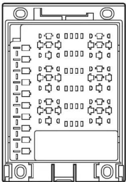
natural_image
Technical line drawing of a mechanical or electrical component with multiple ports and mounting holes (no text or symbols)Contents
1 Preliminary note 4
1.1 Symbols used.... 4
1.2 Warning signs used 4
2 Safety instructions 5
2.1 General....5
2.2 Target group 5
2.3 Electrical connection 5
2.4 Tampering with the device 5
3 Functions and features 6
3.1 Features at a glance. 6
3.2 Items supplied 6
3.3 ecomatmobile Basic (examples) 6
4 Installation....7
4.1 General installation instructions 7
4.1.1 Protection rating....7
4.1.2 Mounting surface 7
4.2 Fixing 8
4.3 Cover and cable seal 9
4.3.1 Overall height and base dimensions of the automotive relay ..... 9
4.3.2 Installation of the cable seal.... 10
4.3.3 Removing the cable seal 10
4.3.4 Installation of the cover .....11
4.3.5 Removing the cover....11
5 Electrical connection.... 12
5.1 General electrical connection.... 12
5.2 Remove the wiring carrier from the base plate. 12
5.3 Supply voltage and ground.... 13
5.3.1 Cut the supply rail 13
5.3.2 Permissible current intensities for 6.3 mm spade terminals.....14
5.3.3 Power distributor 14
5.4 Automotive relays.... 15
5.4.1 Simultaneous triggering of the relays.... 15
5.5 Automotive fuses 16
5.6 Spade sockets 17
5.7 Connection accessories 17
6 Display elements 18
7 Set-up.... 18
8 Operation 18
9 Technical data.... 19
10 Maintenance, repair and disposal. 21
10.1 Maintenance....21
10.2 Cleaning the housing surface.... 21
10.3 Repair....21
10.4 Disposal 21
11 Approvals/standards 21
UK
This document is the original instructions.
Licences and trademarks
Microsoft ^® , Windows ^® , Windows XP ^® , Windows Vista ^® and Windows 7 ^® are registered trademarks of Microsoft Corporation. All trademarks and company names are subject to the copyright of the respective companies.
1 Preliminary note
This document applies to devices of the type "BasicRelay" (art. no.: CR0421). These instructions are part of the device.
This document is intended for specialists. These specialists are people who are qualified by their appropriate training and their experience to see risks and to avoid possible hazards that may be caused during operation or maintenance of the device. The document contains information about the correct handling of the device.
Read this document before use to familiarise yourself with operating conditions, installation and operation. Keep this document during the entire duration of use of the device.
Adhere to the safety instructions.
1.1 Symbols used
▶ Instructions
Reaction, result
[...] Designation of pushbuttons, buttons or indications
→ Cross-reference

Important note
Non-compliance can result in malfunction or interference.

Information
Supplementary note
1.2 Warning signs used
WARNING
Warning of serious personal injury.
Death or serious irreversible injuries may result.
CAUTION
Warning of personal injury.
Slight reversible injuries may result.
NOTE
Warning of damage to property.
2 Safety instructions
2.1 General
These instructions contain texts and figures concerning the correct handling of the device and must be read before installation or use.
Observe the operating instructions. Non-observance of the instructions, operation which is not in accordance with use as prescribed below, wrong installation or incorrect handling can seriously affect the safety of operators and machinery.
2.2 Target group
These instructions are intended for authorised persons according to the EMC and low-voltage directives. The device must only be installed, connected and put into operation by a qualified electrician.
2.3 Electrical connection
Disconnect the unit externally before handling it. If necessary, also disconnect any independently supplied output load circuits.
If the device is not supplied by the mobile on-board system (12/24 V battery operation), it must be ensured that the external voltage is generated and supplied according to the criteria for safety extra-low voltage (SELV) as this voltage is supplied without further measures to the connected controller, the sensors and the actuators.
The wiring of all signals in connection with the SELV circuit of the device must also comply with the SELV criteria (safety extra-low voltage, safe electrical isolation from other electric circuits).
If the supplied SELV voltage is externally grounded (SELV becomes PELV), the responsibility lies with the user and the respective national installation regulations must be complied with. All statements in this document refer to the device the SELV voltage of which is not grounded.
The connections may only be supplied with the signals indicated in the technical data and/or on the device label and only the approved accessories of ifm electronic may be connected.
2.4 Tampering with the device
In case of malfunctions or uncertainties please contact the manufacturer. Tampering with the device can seriously affect the safety of operators and machinery. It is not permitted and leads to the exclusion of any liability and warranty claims.
3 Functions and features
BasicRelay is a freely wirable carrier for use with standardised automotive relays and automotive fuses. The allocation of the contacts, the wiring and the placement are made by the user.
Application-specific extensions and adaptations are possible in conjunction with additional products of the modular ecomatmobile Basic products.

WARNING
The device is not approved for safety-related tasks in the field of operator protection.
NOTE
The device is intended for installation in vehicle bodies, not in engines.
3.1 Features at a glance
- Locations for 6 automotive relays and 10 automotive fuses
• Supply chain can be cut - Power distributor for 6.3 mm spade terminals
3.2 Items supplied
The device is supplied without contacts and without relays and fuses.
3.3 ecomatmobile Basic (examples)
- BasicController (art. no.: CR040x)
mobile controller, freely programmable to IEC 61131-3
2 CAN interfaces (incl. interface for BasicDisplay CR0451)
configurable inputs/outputs - BasicDisplay (art. no.: CR0451)
programmable display with graphics capabilities with 2.8" colour display CAN interface
5 freely programmable, backlit function keys
1 scroll key for cursor function
• Cover (art. no.: EC0401)
incl. cable seal to obtain IP 54 protection
For information about the available ecomatmobile Basic see:
www.ifm.com → Product line → Systems for mobile machines or directly
www.ifm.com → Data sheet search → e.g. CR0451
4 Installation
4.1 General installation instructions
4.1.1 Protection rating
The achievable protection rating of the device depends on the accessories used and the mounting position.
| Protection rating | Accessories Mounting position Art. no. | ||
| IP 20 – freely selectable – | |||
| IP 54 cover with cable seal cable connection from the bottom | EC0401 |
UK
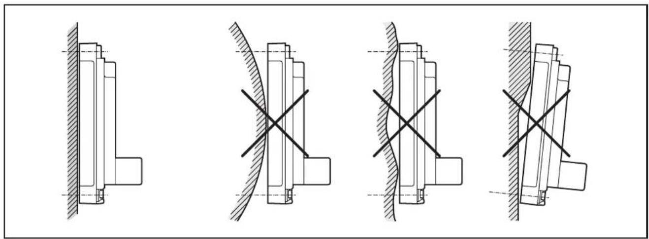
4.1.2 Mounting surface
NOTE
The housing must not be exposed to any torsional forces or mechanical stress.
▶ Mount the device on a flat surface.
▶ Use compensating elements if there is no flat mounting surface available.
natural_image
Four technical diagrams showing mechanical assembly or assembly states with cross-hatching and hatching patterns (no text or symbols)Mounting surface
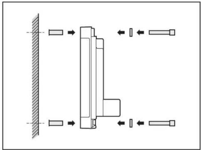
4.2 Fixing
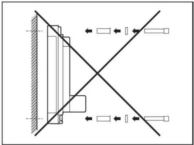
▶ Insert the enclosed tubular rivets from the back of the module in the 4 fixing holes.
▶ Fix the module using 4 washers and M4 screws.
Tighten the screws alternately crosswise.
natural_image
Pure mechanical assembly diagram showing a vertical beam mounted on a stepped component with directional arrows indicating motion (no text or symbols)Use of the tubular rivets
natural_image
Pure mechanical diagram showing a vertical component with diagonal lines and directional arrows, no text or symbols present.Tightening torque: 1.5 Nm
Hole dimensions (→ 9 Technical data)
| Screws to be used (examples): Standard | |
| Cylinder screws with hexagon socket (M4 x L) DIN EN ISO 4762: 2004-06 | |
| Cylinder screws with hexagon socket and low head (M4 x L) DIN 7984: 2009-06 |
4.3 Cover and cable seal
NOTE
Protection IP 54 can only be guaranteed if the cover is used together with the cable seal.
NOTE
The cover reduces the amount of heat to be dissipated.
With a cover fitted the temperature of the unit can therefore increase.
4.3.1 Overall height and base dimensions of the automotive relay
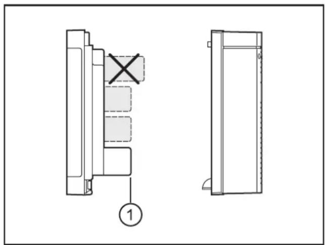
Overall height of the relay with EC0401 cover: ≤ 26 mm
Overall height of the relay: freely selectable

As a principle use automotive relays without mounting brackets.
The mounting brackets cannot be used in conjunction with the device and would unnecessarily increase the height of the relay.

The elevated housing part above the supply and ground connections is the height reference for the automotive relay.
The automotive relays must not be higher than this housing part if a cover is to be used.
natural_image
Technical line drawing of a door panel with cross symbol and numbered label (no text or symbols present)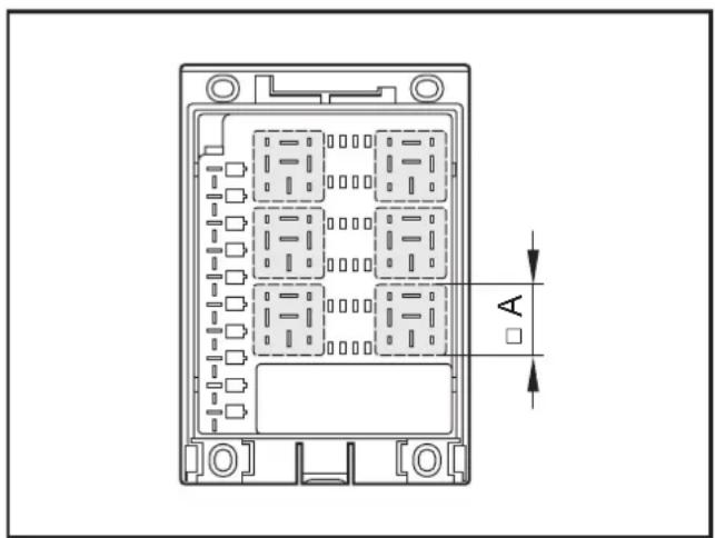
1: Height reference for the automotive relay Max. base dimensions of the automotive relay
Max. base dimensions A: 30 x 30mm
4.3.2 Installation of the cable seal
▶ Insert the cable seal into the locator from below.
The locking of the cable seal audibly clips into place.
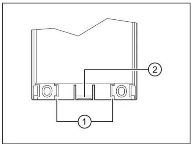
- Locator for cable seal
- Locking
natural_image
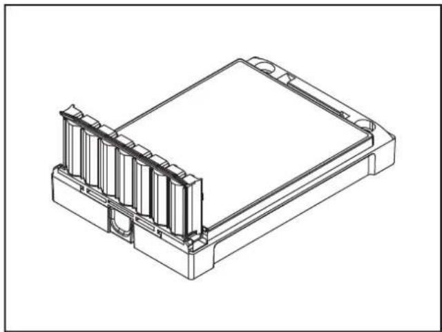
Technical line drawing of a rectangular electronic component with multiple side slots and mounting brackets (no text or symbols)Mounted cable seal

The cable seal cannot be used as strain relief of the cables.(→ 5.1 General electrical connection)
4.3.3 Removing the cable seal
▶ Press the locking at the bottom of the device and remove the cable seal from the device by pulling downwards.
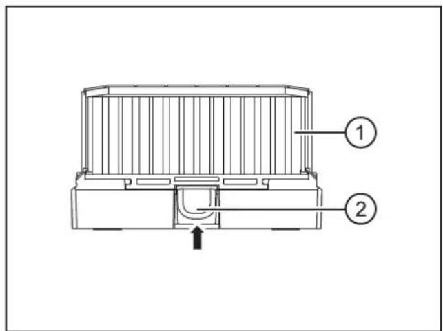
Bottom of the device
- Cable seal
- Locking
4.3.4 Installation of the cover
The covers of the Basic series feature a single-lever locking. Installation is done without tools.
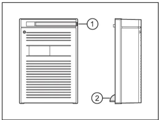
Cover
1: Locking lever
2: Cover guides
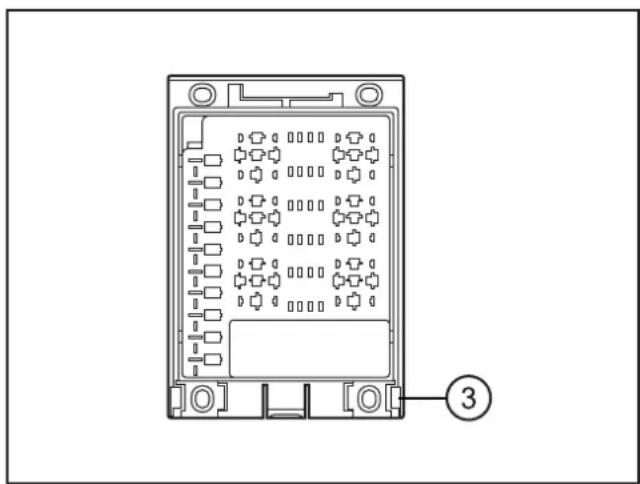
natural_image
Technical line drawing of a device rear panel with mounting holes and internal grid layout (no text or symbols)BasicRelay
3: Insertion slots for cover guides
▶ Pull out the locking lever and rotate it towards you.
▶ Place the cover diagonally onto the device.
Insert the 2 cover guides, found at the bottom of the cover, into the slots.
▶ Close the cover onto the lower part.
The 2 guides and slots provide a pivot point.
▶ Move the locking lever back into its initial position.
The cover is locked.
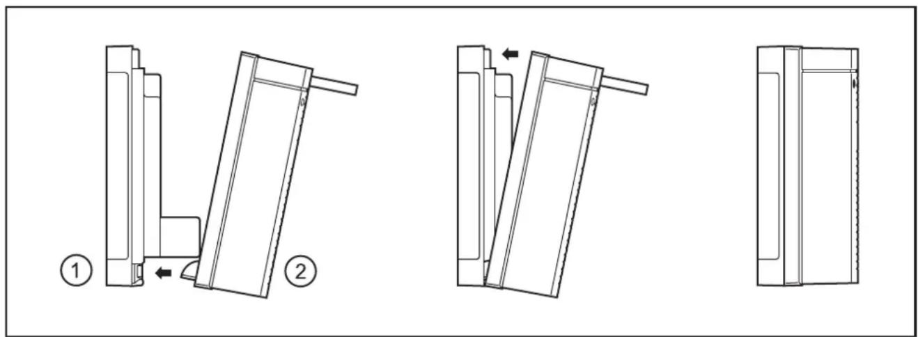
1: BasicRelay
2: Cover
4.3.5 Removing the cover
▶ Pull out the locking lever and rotate it towards you.
The cover is unlocked and can be removed.
5 Electrical connection
5.1 General electrical connection
Core cross-sections and wiring diagram ( 9 Technical data)
▶ Lay supply and signal cables away from the device using the shortest possible route.
▶ All connected cables must be provided with a strain relief at least 100 mm behind the cable entry.

WARNING
The user is responsible for the safe function of the circuits which he created himself. If necessary, he must additionally carry out an approval test by corresponding supervisory and test organisations according to the national regulations.

WARNING
The user must ensure that malfunction due to bent cable connections or loose spade terminals does not impair the safety of people and equipment.
5.2 Remove the wiring carrier from the base plate
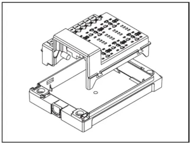
Wiring and power supply connections are made on the rear of the wiring carrier. To do so, the wiring carrier has to be removed from the base plate of the device.
▶ Detach the snap-in lugs between wiring carrier and the base plate of the device on one long side by applying slight pressure.
Alternatively, carefully lever out the snap-in pins on one long side using a screwdriver.
▶ Remove the wiring carrier.
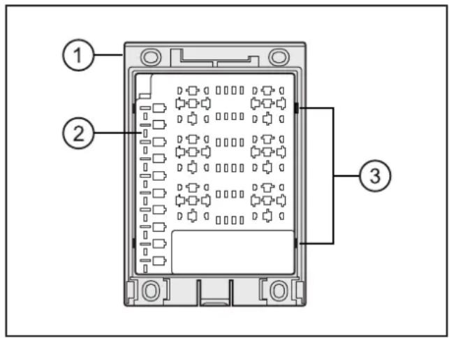
Front of the complete device
1: Base plate of the device
2: Wiring carrier
3: Snap-in lugs (2 on each long side)
natural_image
Technical line drawing of an electronic component assembly (no text or symbols visible)Base plate of the device and wiring carrier
5.3 Supply voltage and ground
▶ Connect the voltage and ground connections via ring terminals (M6/M8) and the threaded suspension rods (M6/M8).
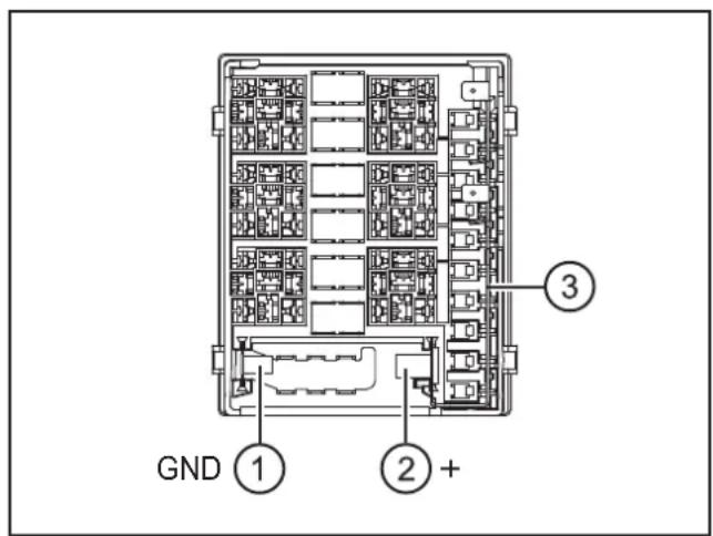
Back of the wiring carrier
1: M6 threaded suspension rod for ground (GND)
2: M8 threaded suspension rod for supply voltage
3: Supply rail to the fuses
Tightening torque M6/M8 threaded suspension rods: 2...3 Nm
5.3.1 Cut the supply rail
The supply rail to the fuses can be mechanically cut at 2 points. The F1/2 and F3/4 or F1...4 fuse lines can be cut from the common supply voltage.
▶ If requested, cut off a piece at the intended point in 2 cuts using a side cutter. Width of this piece: ≥ 5 mm
▶ Supply the separated fuse lines via the allotted 6.3 mm spade terminals.
▶ Observe the maximum total currents ( 9 Technical data)
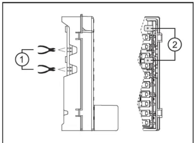
1: Separation points in the supply rail
2: 6.3 mm spade terminals for separated fuse lines
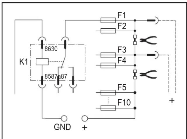
Principle of wiring (example)
5.3.2 Permissible current intensities for 6.3 mm spade terminals
According to pre-standard DIN 46249-1: 1980
| Core cross-section [mm2] Max. current intensity [A] * | |
| 2.5 16 | |
| 4.0 18 | |
| 6.0 22 | |
*) at max. ambient temperature
5.3.3 Power distributor
▶ Connect the power distributor only to protected circuits.
5.4 Automotive relays
The device is suited for automotive relays with a blade arrangement to ISO 7588-1: 1998-09.

Observe the wiring and the documentation of the relays used. The terminal designations can vary.
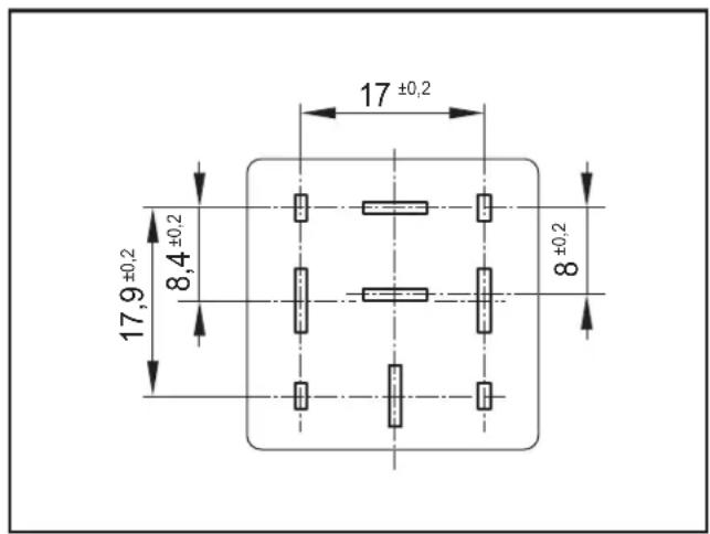
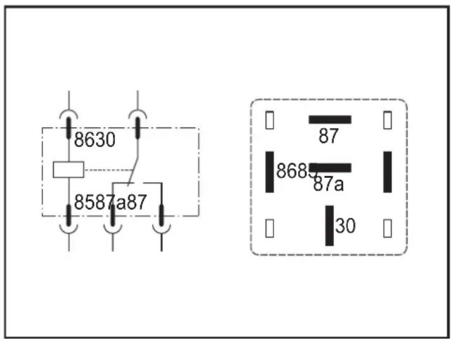
Blade arrangement Connection example to DIN 72552: 1971-03 and
ISO 7588-1: 1998-09
| Terminal designation to DIN 72552: 1971-03 (excerpt) Contact | |
| Positive connection trip coil 86 | |
| Ground connection trip coil 85 | |
| Continuous positive of the battery 30 | |
| NC contact to the load 87a | |
| NO contact to the load 87 |
5.4.1 Simultaneous triggering of the relays
Typically 3 relays may be triggered simultaneously.
▶ Observe the note on operation ( 8 Operation).
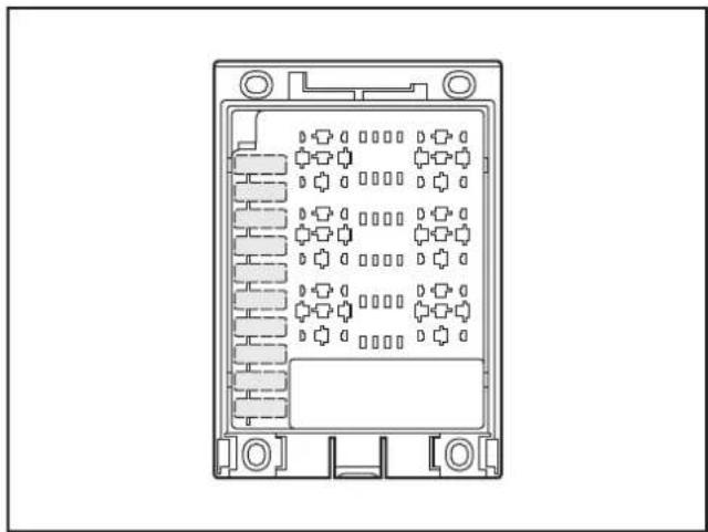
5.5 Automotive fuses
The device is suited for automotive fuses (spade-type fuses) to DIN 72581-3:1971-03 and ISO 8820-3:1971-03, standard design, type C.
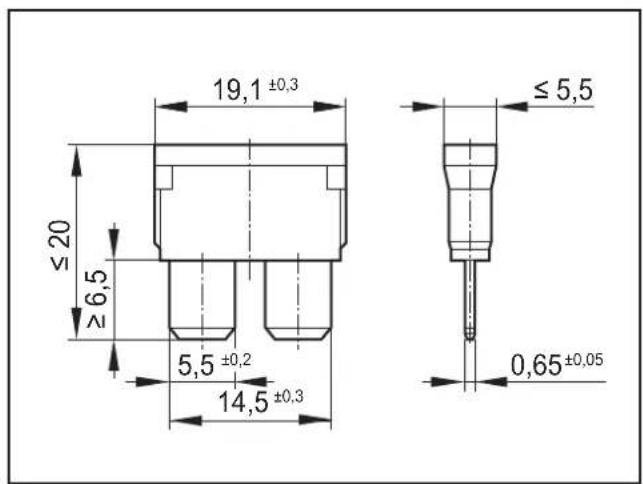
natural_image
Technical line drawing of a rectangular electronic device with internal circuitry and mounting holes (no text or symbols)Dimensions Locations for fuses
| Colour coding to DIN 72581-3: 1971-03 (rated current[A]) | ||||||||||||
| 1 2 3 4 5 | 7.5 10 | 15 20 25 30 | 35 40 | |||||||||
| black | grey | violet | pink | beige | brown | red | blue | yellow | clear | green | teal | orange |
NOTE
Adhere to the manufacturer's information and the nominal current derating for dimensioning the fuse.
Nominal current of the load ≤ 50 % of the rated current of the fuse
5.6 Spade sockets
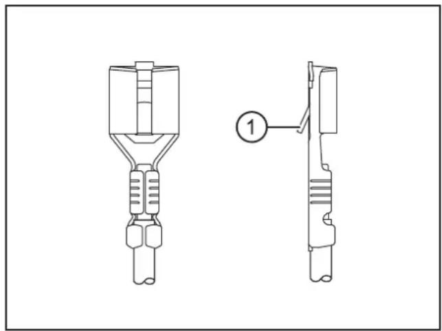
The device is suited for spade sockets to DIN 46340-3: 1981.
▶ When placing the spade sockets into the contact holders, make sure that the locating lugs snap-in securely. The lugs audibly clip into place.
natural_image
Technical line drawing of two mechanical components with no visible text or symbols1: Locating spade socket
UK
5.7 Connection accessories
You can find more information about the available accessories at: www.ifm.com → Data sheet search → e.g. CR0421 → Accessories
6 Display elements
The device does not have any indicators.

If the EC0401 cover is used as accessory, the LED lighting in the cover is without function.
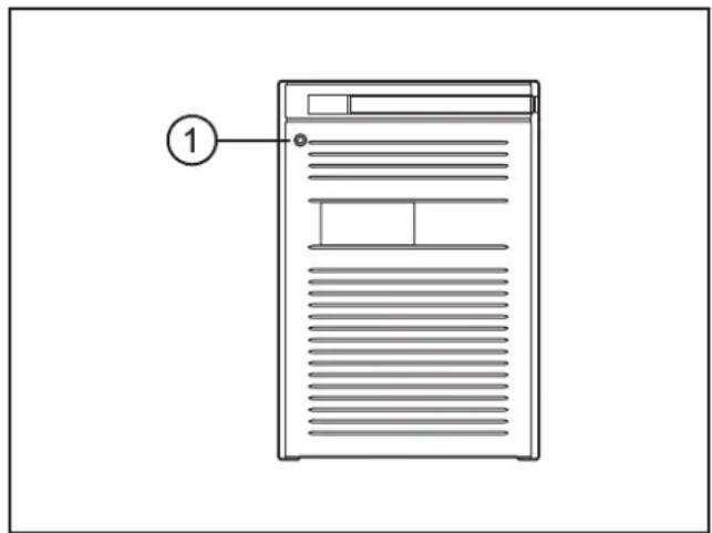
1: The LED lighting in the EC0401 cover
7 Set-up
▶ After completing component assembly and wiring, check the function of the device at max. operating conditions in normal operation and in fault condition.
8 Operation
NOTE
The max. temperatures at the metal or plastic parts of the device must not permanently (> 10 minutes) exceed 110^ C.
9 Technical data
CR0421
BasicRelay
Locations
for 6 automotive relays and 10 automotive fuses
Supply rails and power distributor freely wirable
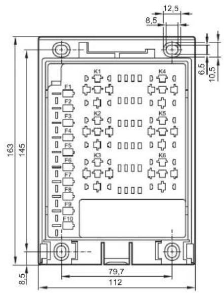
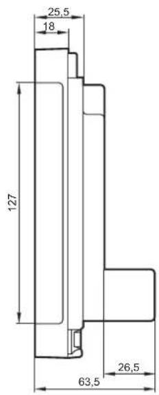
Technical data Wiring, relay and fuse
| Mechanical data |
| Housing plastic housing (black) |
| Dimensions (H x W x D) without cover with EC0401 cover |
| Installation |
| Connection |
| Relay 6 locations for automotive relays |
| carriercan be used with BasicController or as stand-alone device |
| 163 x 112 x 63.5 mm163 x 112 x 68 mm |
| fixing by means of 4 M4 screws to DIN EN ISO 4762: 2004-06 or DIN 7984: 2009-06 and 4 tubular rivets to DIN 7340 (tubular rivets are supplied) |
| (30 x 30 x 26 mm (H x W x D), without contacts, with cover installed)contacts for each relay:5 contact holders for spade sockets 6.3 x 0.8, DIN 46340/T3core cross-section 0.5...2.5 mm^2 4 contact holders for spade sockets 2.8 x 0.8, DIN 46340/T1core cross-section 0.5...1.0 mm^2 |
| up to 30 Acontacts: common supply rail and 10 contact holders for fuse contactssupply rail can be cut at 2 points; 2 x 2 fuses can therefore be supplied separatelyvia 6.3 x 0.8 mm spade terminalscore cross-section 0.5...3.0 mm^2 |
| I for supply voltage to the fusesM6 threaded suspension rod for ground connection (GND) to 6 spade terminals6.3 x 0.8 mmcore cross-section 0.5...16.5 mm^2 |
| ups each with 4 spade terminals 6.3 mm x 0.8 mm |
| (with cover and cable seal IP 54) |
| / -40...85°C |
ifm electronic gmbh • Friedrichstraße 1 • 45128 Essen
We reserve the right to make technical alterations without prior notice! 20.07.2012CR0421 / page 1
| CR0421 Technical data | |
| Electrical data | |
| Operating voltage ≤ 32 V DC | |
| Load current per fuseTotal currents | F1...F10: max. 30 AF1...F4: max. 20 A; F1...F10: max. 60 A |
| Test standards and regulations | |
| Climatic tests EN 60068-2-30: 2006 Damp heat, cyclicupper temperature 55°C, number of cycles: 6 | |
| Mechanical tests ISO 16750-3: 2007 Test VII; Vibration, randommounting location: vehicle body | |
| Wiring diagram | |
| Rear view of the wiring carrier | 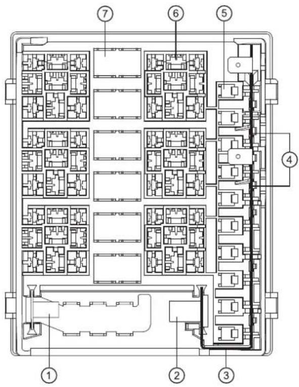 |
| 1: M6 threaded suspension rod for GND2: M8 threaded suspension rod for supply voltage3: Supply rail to the fuses4: Separation points in the supply rail5: Locations for F1...10 fuses6: Locations for K1...6 automotive relays7: Common terminal groups with spade terminals | |
10 Maintenance, repair and disposal
10.1 Maintenance
The device does not contain any components that need to be maintained by the user.
10.2 Cleaning the housing surface
▶ Disconnect the device.
▶ Clean the device from dirt using a soft, chemically untreated and dry cloth.
▶ In case of heavy dirt, use a damp cloth.

The following agents are not suited for cleaning the device: chemicals dissolving plastics such as methylated spirit, benzine, thinner, alcohol, acetone or ammonia.

Micro-fibre cloths without chemical additives are recommended.
10.3 Repair
▶ The device must only be repaired by the manufacturer.
Observe the safety instructions ( 2.4 Tampering with the device)
10.4 Disposal
▶ Dispose of the device in accordance with the national environmental regulations.
11 Approvals/standards
Test standards and regulations ( 9 Technical data)
The EC declaration of conformity and approvals can be found at: www.ifm.com → Data sheet search → CR0421 → Approvals
- Contents
- Licences and trademarks
- Preliminary note
- Symbols used
- Warning signs used
- WARNING
- CAUTION
- NOTE
- Safety instructions
- General
- Target group
- Electrical connection
- Tampering with the device
- Functions and features
- Features at a glance
- Items supplied
- ecomatmobile Basic (examples)
- Installation
- General installation instructions
- Protection rating
- Mounting surface
- Fixing
- Cover and cable seal
- Overall height and base dimensions of the automotive relay
- Installation of the cable seal
- Removing the cable seal
- Installation of the cover
- Removing the cover
- Electrical connection
- General electrical connection
- Remove the wiring carrier from the base plate
- Supply voltage and ground
- Cut the supply rail
- Permissible current intensities for 6.3 mm spade terminals
- Power distributor
- Automotive relays
- Simultaneous triggering of the relays
- Automotive fuses
- Spade sockets
- Connection accessories
- Display elements
- Set-up
- Operation
- Technical data
- CR0421
- Maintenance, repair and disposal
- Maintenance
- Cleaning the housing surface
- Repair
- Disposal
- Approvals/standards
Brand : IFM
Model : EC0457
Category : Relay