
AL4022 - Input/output module IFM - Free user manual and instructions
Find the device manual for free AL4022 IFM in PDF.


| Product Type | Remote I/O Module |
| Model | AL4022 |
| Manufacturer | IFM Electronic |
| Digital Inputs | 16 (8 ports, 2 per port) |
| Communication Interface | EtherNet/IP (Adapter, DLR, QoS) |
| Power Supply (US) | 24 V DC (20...30 V), SELV/PELV, L-coded M12 |
| Sensor Supply | 8 x US, total current limited to 3.6 A |
| Protection Rating | IP65, IP66, IP67 |
| Ambient Temperature | -40 to 100 °C (with derating) |
| Input Filter Functions | Debounce (0-50 ms), Hold (0-6000 ms), Invert |
| Counter Modes | CTU, CTD, CTUD, CTDIR (main + batch counters) |
| Configuration Options | ifm moneo, IoT Core (REST API, Visualizer), EtherNet/IP |
| LED Indicators | Status (RDY, NET, MOD), Ethernet (LNK, ACT), Voltage (US), Process (DI1, DI2) |
| Ethernet Ports | 2 x M12 (X21, X22), DLR capable |
| Process Connection | 8 x M12 (X01-X08), max cable length 30 m |
| Voltage Supply Connector | L-coded M12 (X31), max torque 0.8 Nm |
| Mounting | M5 screws, torque 1.8 Nm, flat surface |
| Housing Material | Not specified (typical metal/plastic) |
| Weight | Not specified (estimated approx. 200 g) |
| Maintenance | Maintenance-free; clean with dry, chemically untreated cloth |
| Safety Features | Reverse polarity protection, overvoltage protection, inrush current limitation, short-circuit/overload detection |
| Cyber Security | Attention to unauthorized access; restrict network access |
Frequently Asked Questions - AL4022 IFM
User questions about AL4022 IFM
0 question about this device. Answer the ones you know or ask your own.
Ask a new question about this device
Download the instructions for your Input/output module in PDF format for free! Find your manual AL4022 - IFM and take your electronic device back in hand. On this page are published all the documents necessary for the use of your device. AL4022 by IFM.
USER MANUAL AL4022 IFM
Operating instructions
Remote I/O module 16 DI
EtherNet/IP
IP65 / IP66 / IP67
AL4022
Contents
1 Preliminary note 5
2 Safety instructions.... 6
2.1 Cyber security.... 6
3 Intended use.... 7
4 Function 8
4.1 Visual indication 8
4.2 Parameter setting 8
4.3 Inputs 8
4.3.1 Sensor supply 8
4.4 Digital input filters 8
4.4.1 Debouncing.... 9
4.4.2 Holding 9
4.4.3 Inverting 10
4.4.4 Filter combination 10
4.5 Counters 10
4.5.1 Counter mode CTU 10
4.5.2 Counter mode CTD.... 11
4.5.3 Counter mode CTUD 11
4.5.4 Counter mode CTDIR 12
4.6 EtherNet/IP 12
5 Installation.... 14
5.1 Install device.... 14
6 Electrical connection.... 15
6.1 Overview.... 15
6.2 General wiring information 15
6.2.1 Connection technology 15
6.3 Ethernet 15
6.4 Process connections.... 16
6.5 Voltage supply 16
6.5.1 Derating behaviour 17
7 Operating and display elements 18
7.1 LEDs.... 18
7.1.1 Status 18
7.1.2 Ethernet 19
7.1.3 Voltage supply 19
7.1.4 Process connections.... 19
8 Set-up 20
9 Settings....21
9.1 Parameter setting software 21
9.1.1 Supported parameter setting software 21
9.1.2 Getting started 21
9.1.2.1 Configure the EtherNet/IP interface.... 21
9.1.3 Fieldbus: Read the interface configuration 22
9.1.4 Fieldbus: Read the connection status 22
9.1.5 Ports: Configure input filters 22
9.1.6 Ports: Read digital input data 23
9.1.7 Counters: Configure counter modules.... 24
9.1.8 Counters: Read counter values.... 25
9.1.9 Counters: Control counter modules.... 25
9.1.10 Gateway: Read identification information 25
9.1.11 Gateway: Read status and diagnostic information.... 26
9.1.12 Gateway: Set the application tag.... 26
9.1.13 Firmware: Read firmware version 27
9.1.14 Firmware: Reset the device.... 27
9.1.15 Firmware: Restart the device 27
9.2 ifm IoT Core 28
9.2.1 ifm IoT Core: General information 28
9.2.1.1 Accessing the ifm IoT Core 28
9.2.2 Getting started 30
9.2.2.1 Notes on configuration 30
9.2.3 General functions 30
9.2.3.1 Example: Outputting the subtree.... 31
9.2.3.2 Example: Reading several elements sequentially 31
9.2.3.3 Example: Changing a parameter value 32
9.2.4 Fieldbus: Read the interface configuration 32
9.2.5 Ports: Configure input filters 33
9.2.6 Ports: Read digital input data 33
9.2.7 Counters: Configure counter modules.... 34
9.2.8 Counters: Control counters 35
9.2.9 Counters: Read and write counter values 35
9.2.9.1 Example: Write counter values 35
9.2.10 Gateway: Read device information 36
9.2.11 Gateway: Read status and diagnostic information.... 36
9.2.12 Gateway: Set the application tag.... 36
9.2.13 Gateway: Update firmware 36
9.2.14 IoT-Core Visualizer 37
9.2.14.1 Start the ifm IoT Core Visualizer 37
9.2.14.2 Search for elements in the device description 38
9.2.14.3 Configure the device 38
9.2.14.4 Access process data.... 38
9.2.14.5 Update firmware 39
9.3 EtherNet/IP 40
9.3.1 Register the EDS file.... 40
9.3.2 Integrate the device into the EtherNet/IP project 40
9.3.3 Set connection types.... 40
9.3.4 Configure input filters 41
9.3.5 Configure counters 42
9.3.6 Read process data of the ports 42
9.3.7 Read counter values and counter events 43
9.3.8 Control counters 43
9.3.9 Acyclic access.... 44
9.3.9.1 Notes on acyclic access 44
10 Maintenance, repair and disposal 45
10.1 Cleaning 45
10.2 Update firmware 45
11 Appendix....46
11.1 ifm IoT Core 46
11.1.1 Profiles 46
11.1.2 Types 46
11.1.3 Services 46
11.1.3.1 Service: factoryreset 46
11.1.3.2 Service: force counter values 46
11.1.3.3 Service: getblobdata 47
11.1.3.4 Service: getdata 47
11.1.3.5 Service: getdatamulti. 47
11.1.3.6 Service: getelementinfo.... 48
11.1.3.7 Service: getidentity 48
11.1.3.8 Service: gettree.... 48
11.1.3.9 Service: install.... 49
11.1.3.10 Service: querytree.... 49
11.1.3.11 Service: reboot 50
11.1.3.12 Service: setblock.... 50
11.1.3.13 Service: setdata 50
11.1.3.14 Service: signal.... 50
11.1.3.15 Service: start_stream_set 50
11.1.3.16 Service: stream_set 51
11.2 EtherNet/IP 52
11.2.1 Parameters 52
11.2.1.1 Configuration Assembly (Instance 198)....52
11.2.1.2 Configuration Assembly (Instance 199)....55
11.2.2 Cyclic data 56
11.2.2.1 Input Assembly (Instance 101) 56
11.2.2.2 Input Assembly (Instance 102) 57
11.2.2.3 Output Assembly (Instance 150).... 58
11.2.3 Acyclical data 59
11.2.3.1 CIP class and instance services 59
11.2.3.2 CIP object classes.... 59
11.2.3.3 Identity Object (Class Code: 0x01) 60
11.2.3.4 Message Router Object (Class Code: 0x02) 62
11.2.3.5 Assembly Object (Class Code: 0x04) 63
11.2.3.6 Connection Manager Object (Class Code: 0x06) 64
11.2.3.7 Device Level Ring Object (Class Code: 0x47)....65
11.2.3.8 Quality Of Service Object (Class Code: 0x48)....66
11.2.3.9 Input Filter Object (Class Code: 0x81)....67
11.2.3.10 Counter Object (Class Code: 0x82)....68
11.2.3.11 LLDP Management Object (Class Code: 0x109)....69
11.2.3.12 TCP/IP Object (Class Code: 0xF5) 70
11.2.3.13 Ethernet Link Object (Class Code: 0xF6) 72
1 Preliminary note
You will find instructions, technical data, approvals and further information using the QR code on the unit / packaging or at www.ifm.com.
2 Safety instructions
- The unit described is a subcomponent for integration into a system.
– The system architect is responsible for the safety of the system.
- The system architect undertakes to perform a risk assessment and to create documentation in accordance with legal and normative requirements to be provided to the operator and user of the system. This documentation must contain all necessary information and safety instructions for the operator, the user and, if applicable, for any service personnel authorised by the architect of the system.
- Read this document before setting up the product and keep it during the entire service life.
- The product must be suitable for the corresponding applications and environmental conditions without any restrictions.
- Only use the product for its intended purpose ( Intended use).
- If the operating instructions or the technical data are not adhered to, personal injury and/or damage to property may occur.
- The manufacturer assumes no liability or warranty for any consequences caused by tampering with the product or incorrect use by the operator.
- Installation, electrical connection, set-up, operation and maintenance of the product must be carried out by qualified personnel authorised by the machine operator.
- Protect units and cables against damage.
- Replace damaged units, otherwise the technical data and safety will be impaired.
2.1 Cyber security
ATTENTION
Operating the machine in an unprotected network environment
▷ Unauthorised read or write access to data is possible.
▷ Unauthorised manipulation of the device function is possible.
▶ Check and restrict access options to the device.
3 Intended use
The unit may only be used for the following purposes:
- Gateway between digital sensors and a higher-level control system
The device is designed for use outside of a control cabinet.
4 Function
4.1 Visual indication
The device displays the following indications:
- Status and error indication of the gateway and the system
- Status and activity indication of the Ethernet connection
- Status display of the voltage supply
- Status, error and short circuit/overload indication of the sensor ports
4.2 Parameter setting
The device can be configured using the following options:
• parameter setting software
- ifm moneo
- ifm moneo|configure SA
- ifm IoT Core - REST-API - IoT-Core Visualizer
- EtherNet/IP projection software
4.3 Inputs
The device has 8 ports. Each port has 2 digital inputs.
4.3.1 Sensor supply
The device has a total of 8 sensor supplies (1 sensor supply per port).
4.4 Digital input filters
The device supports preprocessing of the digital input signals. The filter result is forwarded as a process value. The following filters can be applied to the input signals in the sequence specified.
- Debouncing
- Stretching
- Inverting

flowchart
graph LR
    A["Digital input"] --> B["Filter module"]
    B --> C["Debouncing"]
    C --> D["Stretching"]
    D --> E["Inverting"]
    E --> F["Counter input"]
    E --> G["Process data"]
Each filter can be configured separately.
The device detects signals of a length of min. 0.23 ms. Shorter signals are not detected.

Periodic signals are only detected reliably if the signal period is at least twice as long as the cycle time.
4.4.1 Debouncing
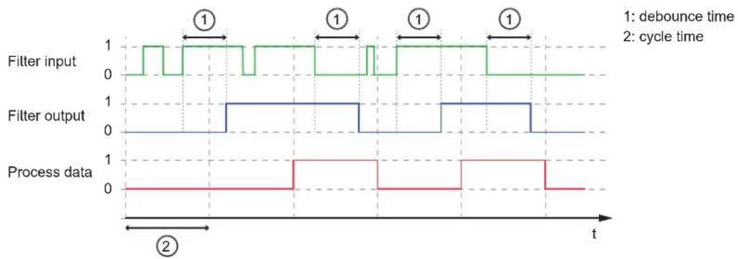
The filter suppresses noise signals. The filter provides the input signals at the filter output with a delay (debounce time). All signals shorter than the set debounce time are ignored by the filter.
Time diagram debounce filter:
line
| Signal | Time Segment | Value | |-----------------|--------------|-------| | Filter input | 1 | 1 | | Filter input | 2 | 0 | | Filter output | 1 | 1 | | Filter output | 2 | 0 | | Process data | 1 | 1 | | Process data | 2 | 0 |4.4.2 Holding
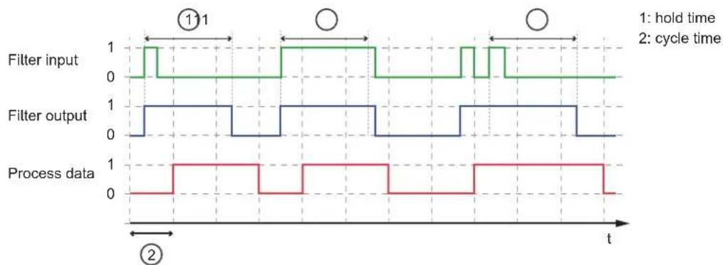
The filter prolongs short input pulses. Level changes that occur during a holding period are ignored. The filter is configured via the following parameters:
- Hold time: pulse duration to which short pulses are to be prolonged. Pulses that are present for a longer time than the hold time are not prolonged.
- Hold level: signal level to be prolonged (HIGH or LOW)
Time diagram hold filter (status HIGH):
line
| Time | Filter input | Filter output | Process data | |------|--------------|---------------|--------------| | 0 | 1 | 1 | 0 | | 1 | 0 | 0 | 0 | | 2 | 1 | 1 | 1 | | 3 | 0 | 0 | 0 | | 4 | 1 | 1 | 1 | | 5 | 0 | 0 | 0 | | 6 | 1 | 1 | 1 | | 7 | 0 | 0 | 0 | | 8 | 1 | 1 | 1 | | 9 | 0 | 0 | 0 | | 10 | 1 | 1 | 1 | | 11 | 0 | 0 | 0 | | 12 | 1 | 1 | 1 | | 13 | 0 | 0 | 0 | | 14 | 1 | 1 | 1 | | 15 | 0 | 0 | 0 | | 16 | 1 | 1 | 1 | | 17 | 0 | 0 | 0 | | 18 | 1 | 1 | 1 | | 19 | 0 | 0 | 0 | | 20 | 1 | 1 | 1 | | 21 | 0 | 0 | 0 | | 22 | 1 | 1 | 1 | | 23 | 0 | 0 | 0 | | 24 | 1 | 1 | 1 | | 25 | 0 | 0 | 0 | | 26 | 1 | 1 | 1 | | 27 | 0 | 0 | 0 | | 28 | 1 | 1 | 1 | | 29 | 0 | 0 | 0 | | 30 | 1 | 1 | 1 | | 31 | 0 | 0 | 0 | | 32 | 1 | 1 | 1 | | 33 | 0 | 0 | 0 | | 34 | 1 | 1 | 1 | | 35 | 0 | 0 | 0 | | 36 | 1 | 1 | 1 | | 37 | 0 | 0 | 0 | | 38 | 1 | 1 | 1 | | 39 | 0 | 0 | 0 | | 40 | 1 | 1 | 1 | | Note: The last two pulses ('') are circled in the image as they are not explicitly provided in the code. The actual pulse values for 'hold time' and 'cycle time' are not provided in the code. There is no additional data series in this view. The label '②' appears below the x-axis at the bottom. The y-axis is labeled 't'.Time diagram hold filter (status LOW):
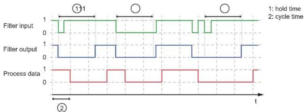
line
| Time | Filter input | Filter output | Process data | |------|--------------|---------------|--------------| | t1 | 1 | 0 | 0 | | t2 | 0 | 1 | 0 | | t3 | 1 | 0 | 1 | | t4 | 0 | 1 | 0 | | t5 | 1 | 0 | 1 | | t6 | 0 | 1 | 0 |4.4.3 Inverting
The filter inverts signals.
4.4.4 Filter combination
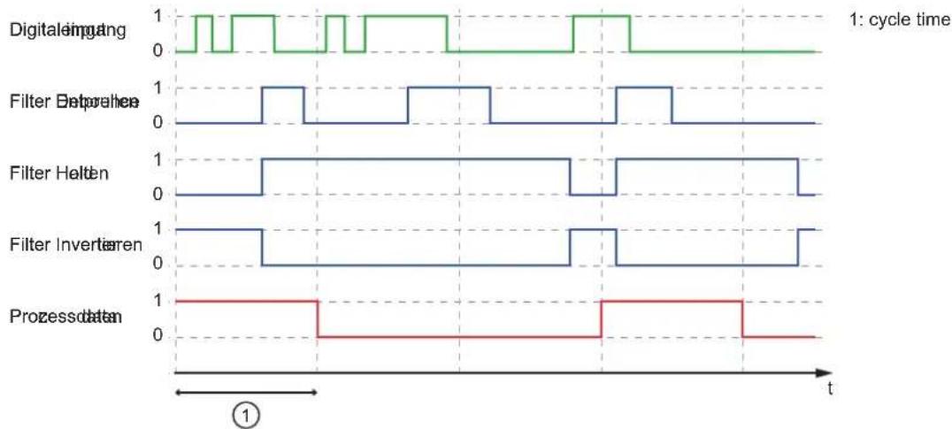
The filters can be combined.
Example: All 3 filters are activated
Time diagram:
line
| Operation | Time Segment | Value | |---------------------|--------------|-------| | Digitaleimgang | 1 | 1 | | Digitaleimgang | 2 | 0 | | Digitaleimgang | 3 | 1 | | Digitaleimgang | 4 | 0 | | Digitaleimgang | 5 | 1 | | Digitaleimgang | 6 | 0 | | Digitaleimgang | 7 | 1 | | Digitaleimgang | 8 | 0 | | Digitaleimgang | 9 | 1 | | Digitaleimgang | 10 | 0 | | Filter Betpoverhe | 1 | 1 | | Filter Betpoverhe | 2 | 0 | | Filter Betpoverhe | 3 | 1 | | Filter Betpoverhe | 4 | 0 | | Filter Betpoverhe | 5 | 1 | | Filter Betpoverhe | 6 | 0 | | Filter Betpoverhe | 7 | 1 | | Filter Betpoverhe | 8 | 0 | | Filter Betpoverhe | 9 | 1 | | Filter Betpoverhe | 10 | 0 | | Filter Helten | 1 | 1 | | Filter Helten | 2 | 0 | | Filter Helten | 3 | 1 | | Filter Helten | 4 | 0 | | Filter Helten | 5 | 1 | | Filter Helten | 6 | 0 | | Filter Helten | 7 | 1 | | Filter Helten | 8 | 0 | | Filter Helten | 9 | 1 | | Filter Helten | 10 | 0 | | Filter Inverteren | 1 | 1 | | Filter Inverteren | 2 | 0 | | Filter Inverteren | 3 | 1 | | Filter Inverteren | 4 | 0 | | Filter Inverteren | 5 | 1 | | Filter Inverteren | 6 | 0 | | Filter Inverteren | 7 | 1 | | Filter Inverteren | 8 | 0 | | Filter Inverteren | 9 | 1 | | Filter Inverteren | 10 | 0 | | Prozessdaten | 1 | 1 | | Prozessdaten | 2 | 0 | | Prozessdaten | 3 | 1 | | Prozessdaten | 4 | 0 | | Prozessdaten | 5 | 1 | | Prozessdaten | 6 | 0 | | Prozessdaten | 7 | 1 | | Prozessdaten | 8 | 0 | | Prozessdaten | 9 | 1 | | Prozessdaten | 10 | 0 |4.5 Counters
The device features one counter module per port.
A counter module consists of 2 separate counters:
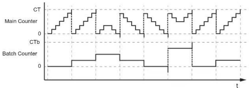
- Main counter: The main counter counts the rising edges of the filtered digital input signals. The main counter has a value range that is defined by a threshold value. If the value range of the main counter is exceeded or not reached, an overflow or underflow signal is sent to the batch counter.
- Batch counter: The batch counter counts the overflow or underflow signals of the main counter.
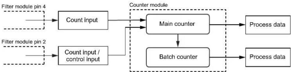
flowchart
graph TD
    A["Filter module pin 4"] --> B["Count input"]
    C["Filter module pin 2"] --> D["Count input / control input"]
    B --> E["Main counter"]
    D --> E
    E --> F["Process data"]
    E --> G["Batch counter"]
    G --> H["Process data"]
    style A fill:#f9f,stroke:#333
    style C fill:#f9f,stroke:#333
    style E fill:#ccf,stroke:#333
    style G fill:#ccf,stroke:#333
    style F fill:#dfd,stroke:#333
    style H fill:#dfd,stroke:#333
A counter module can be operated in different operating modes. The following operating modes are available.
4.5.1 Counter mode CTU
In CTU (Count Up) mode, the counter module operates as an up counter with overflow detection and overflow counter.
Behaviour:
- The initial value of the main counter is m = 0 . The initial value of the batch counter is b = 0 . The main counter has a threshold value CT. The batch counter has a threshold value CTb.
- If the counter module detects a positive edge at pin 4 of the port, the value of the main counter is incremented (m = m+1).
- If the main counter reaches the threshold value CT (m = CT), the counter value is reset (m = 0). Due to the overflow detection, the value of the batch counter is incremented (b = b+1).
- If the batch counter reaches the threshold value CTb (b = CTb), the counter value is reset (b = 0)
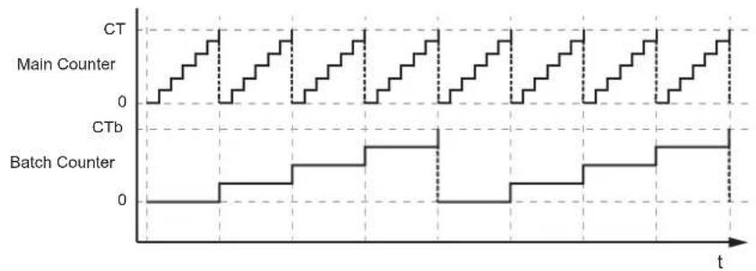
line
| Signal | Value | | ------------ | ----- | | CT | 0 | | Main Counter | 0 | | CTb | 0 | | Batch Counter| 0 |4.5.2 Counter mode CTD
In CTD (Count Down) mode, the counter module operates as a down counter with underflow detection and underflow counting.
Behaviour:
- The initial value of the main counter is m = 0 . The initial value of the batch counter is b = 0 . The main counter has a threshold value CT. The batch counter has a threshold value CTb.
- The first time a positive edge is detected at pin 4, the value of the main counter is set to the threshold value CT-1 (m = CT-1). At the same time, the value of the batch counter is set to the threshold value CTb-1 (b = CTb-1).
- If the counter module detects a positive edge at pin 4 of the port, the value of the main counter is decremented (m = m-1).
- If the main counter falls below 0, the counter value is reset to the threshold value (m = CT-1). Due to the underflow detection, the value of the batch counter is decremented (b = b-1).
- If the batch counter falls below 0, the counter value is reset to the threshold value (b = CTb-1).
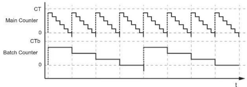
line
| Signal | Value | | ------------- | ----- | | CT | High | | Main Counter | Low | | CTb | 0 | | Batch Counter | Low |4.5.3 Counter mode CTUD
In CTUD (Count Up Down) mode, the counter operates as a simultaneous up and down counter with overflow and underflow detection.
Behaviour:
- The initial value of the main counter is m = 0 . The initial value of the batch counter is b = 0 . The main counter has a threshold value CT. The batch counter has a threshold value CTh
- If the counter module detects a positive edge at pin 4 of the port, the value of the main counter is incremented (m = m+1).
- If the counter module detects a positive edge at pin 2 of the port, the value of the main counter is decremented (m = m-1).
- If the counter module simultaneously detects a positive edge at pin 4 and pin 2 of the port, the counter value of the main counter does not change.
- If the main counter reaches the threshold value CT (m = CT), the counter value is reset (m = 0). Due to the overflow detection, the value of the batch counter is incremented (b = b + 1).
- If the main counter falls below 0, the counter value is reset to the threshold value (m = CT-1). Due to the underflow detection, the value of the batch counter is decremented (b = b-1).
- If the batch counter reaches the threshold value CTb (b = CTb), the counter value is reset (b = 0).
- If the batch counter falls below 0, the counter value is reset to the threshold value (b = CTb-1).
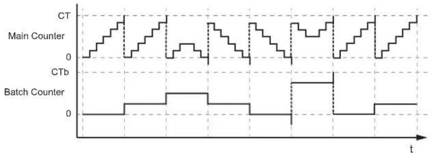
line
| Signal | Value | | ------------- | ----- | | CT | 0 | | Main Counter | 0 | | CTb | 0 | | Batch Counter | 0 |4.5.4 Counter mode CTDIR
In CTDIR (Count Direction) mode, the counter module operates either as an up counter with overflow detection or as a down counter with underflow detection. The counting direction can be set.
Behaviour:
- The initial value of the main counter is m = 0 . The initial value of the batch counter is b = 0 . The main counter has a threshold value CT. The batch counter has a threshold value CTb.
- The user can determine the counting direction. The counter module initially operates as an up counter with overflow detection.
- If the counter module detects a positive edge at pin 4 of the port and the counting direction of the port is set to "up", the value of the main counter is incremented (m = m+1).
- If the main counter reaches the threshold value CT (m = CT), the counter value is reset (m = 0). Due to the overflow detection, the value of the batch counter is incremented (b = b+1).
- If the batch counter reaches the threshold value CTb (b = CTb), the counter value is reset (b = 0).
- If the counter module detects a positive edge at pin 4 of the port and the counting direction at pin 2 of the port is set to "down", the value of the main counter is decremented (m = m-1).
- If the main counter falls below 0, the counter value is reset to the threshold value (m = CT-1). Due to the underflow detection, the value of the batch counter is decremented (b = b-1).
- If the batch counter falls below 0, the counter value is reset to the threshold value (b = CTb-1).
line
| Signal | Value | | ------------- | ----- | | CT | 0 | | Main Counter | 0 | | CTb | 0 | | Batch Counter | 0 |4.6 EtherNet/IP
The unit supports the following EtherNet/IP functions:
• Device type: EtherNet/IP adapter
• Device Level Ring (DLR) - Media Redundancy
- Address Conflict Detection (ACD)
• Quality of Service (QoS)
5 Installation
5.1 Install device

▶ Disconnect the power of the machine before installation.
▶ Use a flat mounting surface for installation.
▶ Please observe the maximum tightening torque.
▶ Fasten the module onto the mounting surface using M5 screws and washers (tightening torque: 1.8 Nm).
6 Electrical connection
6.1 Overview
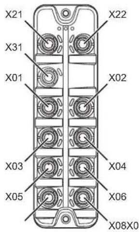
X21: Ethernet 1 (EtherNet/IP)
X22: Ethernet 2 (EtherNet/IP)
X31: power IN
X01: process connection 1 (sensor)
X02: process connection 2 (sensor)
X03: process connection 3 (sensor)
X04: process connection 4 (sensor)
X05: process connection 5 (sensor)
X06: process connection 6 (sensor)
X07: process connection 7 (sensor)
X08: process connection 8 (sensor)
6.2 General wiring information
The unit must be connected by a qualified electrician.
▶ Observe the national and international regulations for the installation of electrical equipment.
The device is only suitable for operation using SELV/PELV voltages.
This device contains components that may be damaged or destroyed by electrostatic discharge (ESD).
▶ Please observe the required precautions against electrostatic discharge.
The circuits are insulated from each other and from touchable surfaces of the device with basic insulation according to EN 61010-1.
The communication interfaces are insulated from each other and from touchable surfaces of the device with basic insulation according to EN 61010-1.
6.2.1 Connection technology
The threaded connections in the device correspond to the M12 standard. To ensure compliance with the specified protection rating, only cables that comply with this standard may be used. In the case of self-assembled cables, the system manufacturer is responsible for the protection rating.
▶ Use connectors with gold-plated contacts.
During installation, place the connectors vertically so that the coupling nut will not damage the thread.
▶ Observe the coding of the connectors during installation.
▶ Cover unused connections with protective covers. Tightening torque: 0.3 ± 0.1 Nm
6.3 Ethernet
The device is connected to the EtherNet/IP network via the Ethernet ports X21 / X22 (e. g. EtherNet/IP control, additional EtherNet/IP device). In addition, the device can be connected to an IT network via the Ethernet ports. Via the IT network, the user can access functions of the ifm IoT Core (configuration tools, REST API, IoT Core Visualizer).
▶ Connect the device to the EtherNet/IP network via a free Ethernet port.
▶ Optional: Connect the device to the IT network via a free Ethernet port.
For connection, use an M12 connector (with at least protection rating: IP65 / IP66 / IP67).
▶ Tighten the cable plug using 1.3 ± 0.1 Nm.
Wiring:

1: TX +
2: RX +
3: TX -
4: RX -
5: not used
6.4 Process connections
The sensors are connected to the device via the process connections.
The total current supply of the ports X01...X08 is limited to 3.6 A.
The ports feature short-circuit / overload detection.
▶ Connect the sensors to ports X01...X08.
For connection, use M12 connectors (with at least protection rating: IP65 / IP66 / IP67; max. cable length: 30 m).
▶ Tighten the cable plug using 1.3 ± 0.1 Nm.
Wiring:

1: sensor supply L+ (US)
2: digital output 2 (DI2)
3: sensor supply L- (US)
4: digital output 1 (DI1)
5: functional earth (FE)
6.5 Voltage supply
The device is connected to the supply voltage US via the power IN port.
The US supply voltage supplies the device and the sensors connected to the ports X01...X08 with voltage.
Port X31 has overvoltage protection (US).
Port X31 has reverse polarity protection (US).
Port X31 has an inrush current limitation.
▶ Disconnect power!
▶ Connect the device via port X31 to 24 V DC (20...30 V SELV/PELV).
For connection, use an L-coded M12 connector (with at least protection rating: IP65 / IP66 / IP67).
▶ Tighten the cable sockets according to the torque specifications indicated by the cable manufacturer. Maximum permissible tightening torque: 0.8 Nm
▶ Observe the derating behaviour of the device ( Derating behaviour ☐ 17).
Wiring:

1: + 24 V DC (US)
2: not used
3: GND (US)
4: not used
6.5.1 Derating behaviour
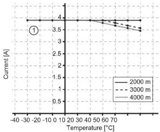
The current IUS available at ports X01...X08 depends on the ambient temperature of the device.
line
| Temperature [°C] | 2000 m | 3000 m | 4000 m | | ---------------- | ------ | ------ | ------ | | -40 | 4.0 | 4.0 | 4.0 | | -30 | 4.0 | 4.0 | 4.0 | | -20 | 4.0 | 4.0 | 4.0 | | -10 | 4.0 | 4.0 | 4.0 | | 0 | 4.0 | 4.0 | 4.0 | | 10 | 4.0 | 4.0 | 4.0 | | 20 | 4.0 | 4.0 | 4.0 | | 30 | 4.0 | 4.0 | 4.0 | | 40 | 4.0 | 4.0 | 4.0 | | 50 | 4.0 | 4.0 | 4.0 | | 60 | 4.0 | 4.0 | 4.0 | | 70 | 4.0 | 3.8 | 3.8 | | 80 | 4.0 | 3.6 | 3.6 | | 90 | 4.0 | 3.5 | 3.5 | | 100 | 4.0 | 3.5 | 3.5 |1: I_us at ports X01...X08
7 Operating and display elements
7.1 LEDs
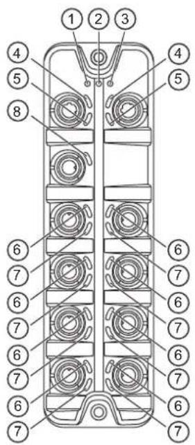
1: status: RDY
2: status: NET
3: status: MOD
4: EtherNet/IP: LNK
5: EtherNet/IP: ACT
6: Process connection: DI1
7: Process connection: DI2
8: voltage supply: US
7.1.1 Status
| LED Description Colour State | Description | |||
| RDY Gateway status - Off Not active or reboots | ||||
| Green Flashes 3 s (1 Hz) DCP | signalling service initiated via fieldbus | |||
| Flashes (200 ms on, 800 ms off) | ||||
| On OK | ||||
| Red On Error during firmware update (e.g. firmware not compatible) | ||||
| NET Network status - Off Not powered, no IP | address: device has no IP address or no voltage applied or voltage applied is too low | |||
| Green / red / yellow | Flashes | |||
| Green Flashes (1 Hz) No connection: no CIP connection established and no exclusive owner connection timeout | ||||
| On Connected: device has IP address and at least one CIP connection established and no exclusive owner connection timeout | ||||
| Red Flashes (1 Hz) Connection: timeout: device has IP address and exclusive owner connection timeout | ||||
| On Duplicate IP: IP address used twice | ||||
| MOD | EtherNet/IP status | -- | Off | |
| Green / red / yellow | Flashes | |||
| Green Flashes (2 Hz) Standby: device is not configured | ||||
| LED Description Colour State Description | ||||
| MOD Ether | Net/IP status Green On | On Device operational: device functions reliably (normal operation) | ||
| Red Flashes (1 Hz) Major recoverable fault: e.g. incorrect configuration | ||||
7.1.2 Ethernet
| LED Description Colour State Description | ||||
| LNK Status of the connection | Green Off | no Ethernet connection | ||
| On Ethernet connection established | ||||
| ACT Status of the data transmission | Yellow Off | no data transmission | ||
| Flashes Data transmission | ||||
7.1.3 Voltage supply
| LED Description Colour State | Description | ||
| US Voltage supply status | - Off No supply voltage is applied or the applied supply voltage is too low | ||
| Green On Supply voltage applied | |||
| Red On Overvoltage, undervoltage, short circuit at sensor supply | |||
7.1.4 Process connections
| LED Description Colour State Description | ||||
| DI1 | Digital input signal level (pin 4) | Yellow Off | Digital input - pin 4: LOW | |
| On Digital input - pin 4: HIGH | ||||
| DI2 | Digital input signal level (pin 2) | Yellow Off | Digital input - pin 2: LOW | |
| On Digital input - pin 2: HIGH | ||||
8 Set-up
▶ Install the unit correctly.
▶ Establish a correct electrical connection with the device.
Once connected to the supply voltage, the unit will start.
The LEDs show status and error conditions.
▷ The unit is ready for operation.
The device can be configured.
9 Settings
9.1 Parameter setting software
9.1.1 Supported parameter setting software
The device can be configured with the following parameter setting software:
- ifm moneo
- ifm moneo|configure SA
▶ Install the desired parameter setting software.
▶ Activate the licences required for operation.
▷ Parameter setting software can be used for parameter setting of the device.

The configuration created with ifm moneo is overwritten when a Configuration Assembly Object is transferred to the device during connection to the EtherNet/IP PLC.
9.1.2 Getting started
Requirements:
√ The parameter setting software is correctly installed on the laptop / PC.
√ The laptop / PC is connected to a free Ethernet port of the device.
▶ Start the parameter setting software.
▶ Scan the network for devices.
The parameter setting software recognises the device.
▶ Optional: Configure the EtherNet/IP interface (→ ☐ 21)
▶ Establish a connection to the device.
The parameter setting software can access the device parameters.
9.1.2.1 Configure the EtherNet/IP interface
The EtherNet/IP interface of the device can be configured using the following options:
- Manually: IP parameters are set by the user
- DHCP: IP parameters are set by a DHCP server in the network
- BOOTP: IP parameters are set via the Bootstrap Protocol

With the parameter setting software ifm moneo or ifm moneo|configure (SA), the IP parameters of the EtherNet/IP interface can only be set during the network scan. In the editor view of the device, the configuration of the EtherNet/IP interface is read-only.
▶ Start the parameter setting software.
▶ Configure the EtherNet/IP interface of the device.
The device has a configured EtherNet/IP interface.
9.1.3 Fieldbus: Read the interface configuration
▶ Observe the notes on the configuration of the EtherNet/IP interface: Configure the EtherNet/IP interface ( ☐ 21)
Available parameters:
| Name Description Value range | Access | ||
| [dhcp] Status of the DHCP client | of the device | Static IP: IP parameters are set by the userDHCP: IP parameters are set by a DHCP server in the networkBOOTP: IP parameters are set via the Bootstrap Protocol | ro ^1 |
| [ipaddress] IP address of the Ethernet/IP interface | etherNet/IP interface | e.g. 192.100.0.10192.168.1.250 (default) | ro ^1 |
| [subnetmask] Subnet mask of the network segment | the network segment | e.g. 255.255.255.0255.255.255.0 (default) | ro ^1 |
| [ipdefaultgateway] IP address of the network gateway e.g. 192.100.0.1 | of the network gateway e.g. 192.100.0.1 | 0.0.0.0 (default) | ro ^1 |
| [macaddress] MAC address of the Ethernet interface | the Ethernet interface | e.g. 00:02:01:0E:10:7F ro | ^1 |
| [hostname] Name of the device | in the EtherNet/IP network | e.g. al4x2x ro | ^1 |
^1 read only
Requirements:
√ The parameter setting software has been started.
√ The detailed view of the device is active.
▶ Select the [fieldbussetup] > [network] menu.
The menu page displays the current configuration of the EtherNet/IP interface.
9.1.4 Fieldbus: Read the connection status
Available information:
| Name Description Value range | Access | ||
| [connectionstatus] | Status of the EtherNet/IP connection | • Disconnected: not connected• Connected: connected | ro ^1 |
| [fieldbusfirmware] | Firmware version of the EtherNet/IP stack | e.g. 3.4.0.7 (EtherNet/IP Adapter) | ro ^1 |
^1 read only
Requirements:
√ The parameter setting software has been started.
√ The detailed view of the device is active.
▶ Select the [fieldbussetup] menu.
The menu page displays the status of the EtherNet/IP connection.
9.1.5 Ports: Configure input filters

▶ Observe the notes on input filters: Digital input filters ( ☐ 8)
Available parameters:
| Name Description Value range Access | |||
| [pin2]/[debounce_time] Pin 2: | debounce time (= value * 0.1 ms) | • 0: 0 ms (default)...• 500: 50 ms | rw^1 |
| [pin2]/[hold_time] Pin 2: hold time (= value * 0.1 ms) • 0: 0 ms (default) | ...• 60000: 6000 ms | rw^1 | |
| [pin2]/[hold_level] Pin 2: hold level • 0: hold LOW | • 1: hold HIGH (default) | rw^1 | |
| [pin2]/[invert] Pin 2: inversion • 0: do not invert (default) | • 1: invert | rw^1 | |
| [pin4]/[debounce_time] Pin 4: | debounce time (= value * 0.1 ms) | • 0: 0 ms...• 500: 50 ms | rw^1 |
| [pin4]/[hold_time] Pin 4: hold time (= value * 0.1 ms) • 0: 0 ms (default) | ...• 60000: 6000 ms | rw^1 | |
| [pin4]/[hold_level] Pin 4: hold level • 0: hold LOW | • 1: hold HIGH (default) | rw^1 | |
| [pin4]/[invert] Pin 4: inversion • 0: do not invert (default) | • 1: invert | rw^1 | |
^1 read and write; can only be changed if no connection to the fieldbus controller is active
▶ Select the menu option [io] > [port[n]] (n: 1...8).
The menu page displays the available parameters.
▶ Set the parameters.
▶ Write the changed parameter values to the device.
The digital input filters have been configured.
9.1.6 Ports: Read digital input data
Available information:
| Name Description Value range | Access | ||
| [pin2]/[digital] Process value digital input - pin 2 (after filtering) | • LOW: off• HIGH: on | ro ^1 | |
| [pin4]/[digital] Process value digital input - pin 4 (after filtering) | • LOW: Off• HIGH: on | ro ^1 | |
^1 read only
Requirements:
√ The parameter setting software has been started.
√ The detailed view of the device is active.
▶ Select the menu option [io] > [port[n]] (n: 1...8).
The menu page displays the current process values of the port's digital inputs.

The displayed process values are the filtered input data.
9.1.7 Counters: Configure counter modules

▶ Observe the notes on counter modules: Counters ( ☐ 10)

If the operating mode of a counter module is changed, the current counter values will be reset and any active events will be deleted.
For the parameters [pin2_function] and [count_direction_selection] all shown parameter values can be selected. It is not checked whether these make sense. For each counter operating mode (parameter [mode]), the table below indicates the valid value ranges (√ : valid setting; × : invalid setting):
| [mode] | [pin2_function] [count_direction_selection] | ||||||
| N/C | Counter Edge Input Pin2 | Count Direction | Reset (Main & Batch Counter) | Disable (Main & Batch Counter) | Pin 2 Count Direction | IoT / PLC Count Direction | |
| CTU | √ × × | √ √ × × | |||||
| CTD | √ × × | √ √ × × | |||||
| CTUD | × √ × | × × × × | |||||
| CTDIR | × × √ | × × √ × | |||||
| CTDIR | √ × × | √ √ × √ | |||||
Available parameters:
| Name Description Value range Access | |||
| [mode] Operating mode of the counter module | • CTU (up counter): up counter (default)• CTD (down counter): down counter• CTUD (up counter / down counter): up and down counter• CTDIR (direction counter): up or down counter | rw^1 | |
| [pin2_function] | Pin 2 function of the port ( Observe note!) | • N/C: no function (default)• Counter Edge Input 2: counting pulse (rising edge)• Count Direction: counting direction• Reset (Main & Batch Counter): reset main counter and batch counter• Disable (Main & Batch Counter): disable main counter and batch counter | rw^1 |
| [count_direction_selection] Control instance for selecting the counting direction ( Observe note!) | • Pin 2 Count Direction: pin 2 of the port (default)• IoT / PLC Count Direction: Fieldbus PLC | rw^1 | |
| [main_threshold] Main counter threshold (CT) • 1 | ...• 4294967295 (default) | rw^1 | |
| [batch_threshold] Batch counter threshold (CTb) • 1 | ...• 65535 (default) | rw^1 |
^1 read and write; can only be changed if no connection to the fieldbus controller is active
Requirements:
√ The parameter setting software has been started.
√ The detailed view of the device is active.
▶ Select the menu option [io] > [counter[n]] (n: 1...8).
The menu page displays the configuration options of the counter.
▶ Configure the counter module.
▶ Optional: Configure additional counter modules.
▶ Write the changed values to the device.
The counter modules are configured.
9.1.8 Counters: Read counter values
Available parameters:
| Name Description Value range Access | ||
| [maincounter_value] Main counter value 0...4294967294 ro | 1 | |
| [batchcounter_value] Batch counter value 0...65534 ro | 1 |
^1 read only
Requirements:
√ The parameter setting software has been started.
√ The detailed view of the device is active.
▶ Select the menu option [io] > [port[n]] (n: 1...8).
The menu page displays the current counter values of the main and batch counter.
9.1.9 Counters: Control counter modules
Available parameters:
| Name Description Value range Access | |||
| [disable] Disable main counter and batch counter | • 0: counter module is active (default)• 1: counter module is not active | rw^1 | |
| [reset] Reset main counter, batch counterand CT and CTb thresholds to initial values | • 0: no action (default)• 1: reset | rw^1 | |
| [direction] ^2 | Set counting direction for main and batch counter | • 0: up (default)• 1: down | rw^1 |
1 read and write; can only be changed if no connection to the fieldbus controller is active
^2 only effective if operating mode of counter module = CTDIR
Requirements:
√ The parameter setting software has been started.
√ The detailed view of the device is active.
▶ Select the menu option [io] > [counter[n]] (n: 1...8).
The menu page displays the available parameters.
▶ Optional: disable counter module.
▶ Optional: reset counter module.
▶ Optional: set counting direction of counter module.
▶ Write the changed parameter values to the device.
▷ Selected actions are executed.
9.1.10 Gateway: Read identification information
Available information:
| Name Description Value range Access | |||
| [productcode] Article number | AL4022 | ro | 1 |
| [devicefamily] Device family Ethernet modules ro | 1 | ||
| [vendor] Manufacturer ifm electronic gmbh ro | 1 | ||
| [swrevision] Firmware revision e.g. AL4x2x_fw_eip_1.4.0.137 ro | 1 | ||
| [hwrevision] Hardware revision (status) e.g. AA ro | 1 | ||
| [bootloaderrevision] | Bootloader version | e.g. AL4xxx_bl_1.2.0.35 | ro 1 |
| [serialnumber] | Serial number | e.g. 0002043100003 | ro 1 |
| [fieldbustype] | Fieldbus | EtherNet/IP | ro 1 |
^1 read only
Requirements:
√ The parameter setting software has been started.
√ The detailed view of the device is active.
▶ Select the menu option [deviceinfo].
The menu page displays the identification information of the device.
9.1.11 Gateway: Read status and diagnostic information
Available information:
| Parameter | Description | Value range | Access |
| [temperature] | Temperature of the device (value in °C) | -30...80 | ro ^1 |
| [voltage_us] | Present voltage value of the device supply US (value in mV) | 0...40000 | ro ^1 |
| [supervisionstatus_us] | Status of the device supply US | 0: no error1: error | ro ^1 |
| [current_us] | Present current value of the device supply US (value in mA) | 0...40000 | ro ^1 |
^1 read only
Requirements:
√ The parameter setting software has been started.
√ The detailed view of the device is active.
▶ Select the menu option [Processdatamaster].
The menu page displays the diagnostic and status information.
9.1.12 Gateway: Set the application tag
Available parameters:
| Parameter | Description | Value range | Access |
| [applicationtag] | Application-specific identifier of the device in moneo | e.g. plant 1 machine 3 | r w ^1 |
^1 read and write
Requirements:
√ The parameter setting software has been started.
√ The detailed view of the device is active.
▶ Select the menu option [devicetag].
▶ Enter the application identifier.
▶ Write the changed values to the device.
The device can be identified by the selected application tag.
9.1.13 Firmware: Read firmware version
Available information:
| Parameter Description Value range Access | ||
| [version] Firmware version e.g. AL4x2x_fw_eip_1.4.0.137 ro | ^1 |
^1 read only
Requirements:
√ The parameter setting software has been started.
√ The detailed view of the device is active.
▶ Select the [Firmware] menu.
The menu page displays the firmware version of the device.
9.1.14 Firmware: Reset the device
Requirements:
√ The parameter setting software has been started.
√ The detailed view of the device is active.
▶ Select the [Firmware] menu.
▶ Click on [factoryreset].
The device will be reset to the factory settings.
▷ All parameters are set to their default values.
9.1.15 Firmware: Restart the device
Requirements:
√ The parameter setting software has been started.
√ The detailed view of the device is active.
▶ Select the [Firmware] menu.
▶ Click on [Reboot].
▷ The device will be restarted.
▷ All set parameter values will be retained.
9.2 ifm IoT Core
9.2.1 ifm IoT Core: General information
The device has the ifm IoT Core. The ifm IoT Core represents the functionality of a device. Each device is represented by a number of objects, services and events. The elements of the ifm IoT Core are arranged in a JSON object in a hierarchical tree structure. The ifm IoT Core makes these elements available to the outside world via standard interfaces. This allows the user and other devices to access data (parameters, process data, events) and functions (services) of the ifm IoT Core.
9.2.1.1 Accessing the ifm IoT Core
An element of the ifm IoT Core is accessed via its address (e.g. root/port1/pin2). The address is composed of the path leading to the element (root/port1) and the identifier of the element (pin2).
The user can access the ifm IoT Core via HTTP requests. The following methods are supported:
GET method
Access: reading
Syntax of the request:
http://ip/datapoint/service
| Parameter Description | |
| ip IP address of the IoT interface | |
| data_point Data point which is to be accessed | |
| service Service | |
Syntax of the response:
{
    "cid": id,
    "data": {"value":"resp_data"},
    "adr": "data_point/service",
    "code": diag_code
}
| Field Parameter | Description | |
| cid id Correlation ID for the assignment of request and reply | ||
| data resp_data Value of the data point; depending on the data type of the data point | ||
| adr data_point Data point accessed | ||
| code diag_code | Diagnostic code Diagnostic codes | |
Example: GET request
- Request:
http://192.168.0.250/devicetag/applicationontag/getdata
- Response:
{
    "cid": -1,
    "data": {"value":"factory 2 plant 1"},
    "adr":"devicetag/applicationtag/getdata",
    "code": 200
}
POST method
Access: reading, writing
Syntax of the request:
{
    "code": "code_id",
    "cid": id,
    "adr": "data_point/service",
    "data": {req_data},
}
| Field Parameter Description | ||
| code code_id Service class | request: Requesttransaction: Transactionevent: Event | |
| cid id Correlation ID for the assignment in pairs of request and return; identifier freely selectable by the user | ||
| adr data_point Data point which is to be accessed | ||
| data ^1 | req_data Data sent to the ifm IoT Core (e.g. new values); syntax depending on the service | |
^1 optional; only required for services that send data to the ifm IoT Core (e.g. setdata)
Syntax of the response:
{
    "cid": id,
    "data": {resp_data},
    "adr": "data_point/service",
    "code": diag_code
}
| Field Parameter Description | ||
| cid id | Correlation ID for the assignment of request and return (→ Request) | |
| data1 | resp_data Values returned by the ifm IoT Core; syntax depending on the service | |
| adr data_point | Data point accessed | |
| service Service that accessed the data point | ||
| code diag_code | Diagnostic code | |
1 optional; only available for services that receive data from the ifm IoT Core (e.g. getdata)
Example: POST request
- Request:
{
    "code":"request",
    "cid":-1,
    "adr":"devicetag/applicationtag/getdata"
}
- Response:
{
    "cid": -1,
    "data": {"value":"Do not use"},
    "adr": "devicetag/applicationtag/getdata",
    "code": 200
}
9.2.2 Getting started
To register the device description:
▶ Send the following POST request to the ifm IoT Core: {"code":"request", "cid":-1, "adr":"gettree"}
▷ ifm IoT Core returns the device description as a structured JSON object.
▶ Identify all substructures and the data points contained therein in the tree structure of the JSON object.
▶ Identify the applicable services for the access to substructures and the data points contained therein.
9.2.2.1 Notes on configuration

The configuration created via the IoT Core (API, IoT Core Visualizer) is overwritten when a Configuration Assembly Object is transferred to the device during a connection to the fieldbus PLC.
9.2.3 General functions
The device has the type "device" ( Types ☐ 46). The following services can be applied to the root element of the device tree:
| Service Description | |
| ../gettree Provide the complete tree or subtree of the device description (JSON) | |
| ../getidentity Read identification information of the device | |
| ../getdatamulti Reading several elements sequentially | |
| ../getelementinfo Reading detailed information of an element | |
| ../getsubscriberlist Print a list of all active notification subscriptions | |
| ../querytree Search device description for specific elements | |
The following services can be applied to elements of the type data depending on its access rights:
| Service Description | |
| ../getdata Reading the value of the element | |
| ../setdata Write the value of the element | |
9.2.3.1 Example: Outputting the subtree
Task: Output all direct sub-elements of the node firmware.
Solution: Use the service gettree to output the required subtree (root node: firmware, sub-levels to be shown: 1)
- Request:
{
    "code": "request",
    "cid": 4711,
    "adr": "gettree",
    "data": {"adr": "firmware", "level": 1}
}
- Response:
{
    "cid":4711,
    "data":{
    "identifier":"firmware",
    "type":"structure",
    "profiles":["software","software/uploadablesoftware","devicereset"],
    "subs":[
    {"identifier":"version","type":"data","profiles":["parameter"],"profiles":["parameter"],"format":
    {"type":"string","namespace":"json","encoding":"UTF-8"}],
    {"identifier":"type","type":"data","profiles":["parameter"],"format":
    {"type":"string","namespace":"json","encoding":"UTF-8"}],
    {"identifier":"factoryreset","type":"service"},
    {"identifier":"install","type":"service"},
    {"identifier":"signal","type":"service"},
    {"identifier":"container","type":"data","profiles":["blob"],"format":
    {"type":"binary","namespace":"json","encoding":"base64"}},
    {"identifier":"reboot","type":"service"}
    ]
    },
    "adr":"gettree",
    "code":200
}
9.2.3.2 Example: Reading several elements sequentially
Task: The following current values of the device are to be read consecutively: Temperature, serial number
Solution: Read the current parameter values using the service getdatamulti (data point temperature: /processdatamaster/temperature; data point serial number: /deviceinfo/serialnumber)
- Request:
{
    "code": "request",
    "cid": 4711,
    "adr": "/getdatamulti",
    "data": {"datatosend": [
    "/processdatamaster/temperature",
    "/deviceinfo/serialnumber"]
    }
}
- Response:
{
    "cid":4711,
    "data":{
    "processdatamaster/temperature":{"code":200,"data":44},
    "deviceinfo/serialnumber":{"code":200,"data":"000174210147"}},
    "adr":/getdatamulti",
    "code":200
}
9.2.3.3 Example: Changing a parameter value
Task: The Application Tag parameter of the device is to be written with the value "Do not use". The new value is only supposed to be valid until the next reboot of the device.
Solution: Write the new value of the /devicetage/applicationtag element with the setdata service. To keep the new value only until the next restart of the device, pass on the duration option with the uptime value.
- Request:
{
    "code":"request",
    "cid":4711,
    "adr":"/devicetag/applicationtag/setdata",
    "data":{"duration":"uptime","newvalue":"Do not use"}
}
- Response:
{
    "cid":4711,
    "adr":"/devicetag/applicationtag/setdata",
    "code":200,
}
9.2.4 Fieldbus: Read the interface configuration
Substructure: fieldbussetup
Available data points:
| Name Description Values Access | |||
| ../network/dhcp Status of the D | HCP client • 0: static IP address | • 1: DHCP• 2: BOOTP | ro ^1 |
| ../network/ipaddress IP address | of the Ethernet interface: e.g. 192.200.0.100 | • 192.168.1.250 (default) | ro ^1 |
| ../network/subnetmask Subnet | mask of the network segment e.g. 255.255.192.0 | • 255.255.255.0 (default) | ro ^1 |
| ../network/ipdefaultgateway IP | address of the network gateway e.g. 192.200.63 | 1• 0.0.0.0 (default) | ro ^1 |
| ../network/hostname Name of device in EtherNet/IP project e.g. al4x2x ro | ^1 | ||
| ../network/macaddress MAC address of the Ethernet interface e.g. 00:02:01:0E | 10:7C ro | ^1 | |
| ../fieldbusfirmware | Version of the EtherNet/IP firmware of the device | e.g. 3.4.0.7 (EtherNet/IP Adapter) | ro ^1 |
| ../connectionstatus | Status of the connection to the EtherNet/IP network | • 0: not connected• 1: connected | ro ^1 |
^1 read only
9.2.5 Ports: Configure input filters

▶ Observe the notes on input filters: Digital input filters ( ☐ 8)
Substructure: io/port[n] (n: 1...8)
Available data points:
| Name Description Values Access | |||
| ../pin2/debounce_time | Pin 2: debounce time (= value * 0.1 ms) | • 0: 0 ms (default)...• 500: 50 ms | rw^1 |
| ../pin2/hold_time | Pin 2: hold time (= value * 0.1 ms) | • 0: 0 ms (default)...• 60000: 6000 ms | rw^1 |
| ../pin2/hold_level | Pin 2: hold level | • 0: hold LOW• 1: hold HIGH (default) | rw^1 |
| ../pin2/invert | Pin 2: inversion | • 0: do not invert (default)• 1: invert | rw^1 |
| ../pin4/debounce_time | Pin 4: debounce time (= value * 0.1 ms) | • 0: 0 ms (default)...• 500: 50 ms | rw^1 |
| ../pin4/hold_time | Pin 4: hold time (= value * 0.1 ms) | • 0: 0 ms (default)...• 60000: 6000 ms | rw^1 |
| ../pin4/hold_level | Pin 4: hold level | • 0: hold LOW• 1: hold HIGH (default) | rw^1 |
| ../pin4/invert | Pin 4: inversion | • 0: do not invert (default)• 1: invert | rw^1 |
1 read and write; can only be changed if no connection to the fieldbus controller is active
9.2.6 Ports: Read digital input data
Substructure: io/port[n] (n: 1...8)
Available data points:
| Name Description Values Access | ||
| ../pin2/digital Process value digital input - pin 2 (after filtering) | • 0: LOW• 1: HIGH | ro ^1 |
| ../pin4/digital Process value digital input - pin 4 (after filtering) | • 0: LOW• 1: HIGH | ro ^1 |
^1 read only
9.2.7 Counters: Configure counter modules

▶ Observe the notes on counter modules: Counters (→ □ 10)

If the operating mode of a counter module is changed, the current counter values will be reset and any active events will be deleted.
For the parameters [pin2_function] and [count_direction_selection] all shown parameter values can be selected. It is not checked whether these make sense. For each counter operating mode (parameter [mode]), the table below indicates the valid value ranges (√: valid setting; ×: invalid setting):
| [mode] | [pin2_function] [count_direction_selection] | ||||||
| No function | Counting pulse | Counting direction | Reset main and batch counter | Disable main and batch counter | Pin 2 | Fieldbus PLC | |
| CTU | √ × × | √ √ × × | |||||
| CTD | √ × × | √ √ × × | |||||
| CTUD | × √ × | × × × × | |||||
| CTDIR | × × √ | × × √ × | |||||
| CTDIR | √ × × | √ √ × √ | |||||
Substructure: io/counter[n] (n: 1...8)
Available data points:
| Name Description Values Access | |||
| ../mode Operating mode of the | counter module • 0: CTU – up counter (default) | • 1: CTD – down counter• 2: CTUD – up and down counter• 3: CTDIR – up and down counter with selectable counting direction | rw ^1 |
| ../pin2_function | Pin 2 function of the port (→ Observe note!) | • 0: no function (default)• 1: counting pulse (rising edge)• 2: counting direction• 3: reset main counter and batch counter• 4: disable main counter and batch counter | rw ^1 |
| ../count_direction_selection Control | control instance for selecting the counting direction (→ Observe note!) | • 0: Pin 2 (default)• 1: Fieldbus PLC | rw ^1 |
| ../main_threshold Main counter | threshold (CT) • 1 | ...• 4294967295 (default) | rw ^1 |
| ../batch_threshold | Batch counter threshold (CTb) | • 1...• 65535 (default) | rw ^1 |
1 read and write; can only be changed if no connection to the fieldbus controller is active
9.2.8 Counters: Control counters
Substructure: io/counter[n] (n: 1...8)
Available data points:
| Name Description Values Access | |||
| ../reset Reset counter module (reset | counter and threshold values to default values) | • 0: no action (default)• 1: reset | rw^1 |
| ../disable Disable counter module • 0: enable counter (default) | • 1: disable counter | rw^1 | |
| ../direction2 | Set counting direction for main and batch counter | • 0: up (default)• 1: down | rw^1 |
1 read and write; can only be changed if no connection to the fieldbus controller is active
^2 only effective if operating mode of counter module = CTDIR
9.2.9 Counters: Read and write counter values
Substructure: io/counter[n] (n: 1...8)
Available data points:
| Name Description Values Access | |||
| ../maincounter_value Current main counter value 0...4294967295 ro | 1 | ||
| ../batchcounter_value Current batch counter value 0...65535 ro | 1 |
^1 read only
Applicable services:
| Name Description | |
| ../force_counter_value | Write counter values of main and batch counter |
9.2.9.1 Example: Write counter values
Task: The counter values of the counter module of port 2 are to be changed (main counter = 100, batch counter = 10).
Solution: Write the new values to the structure io/counter[2] with the service force_counter_value.
- Request:
{
    "code": "request",
    "cid": 4711,
    "adr": "io/counter[2]/force_counter_value",
    "data": {"maincounter_value": 100, "batchcounter_value": 10}
}
- Response:
{
    "cid":4711,
    "adr":"io/counter[2]/force_counter_value",
    "code":200
}
9.2.10 Gateway: Read device information
Substructure: deviceinfo
Available data points:
| Name Description Values Access | |||
| ../productcode Article number AL4022 ro | ^1 | ||
| ../vendor Manufacturer ifm electronic ro | ^1 | ||
| ../devicefamily Device family Remote IO ro | ^1 | ||
| ../serialnumber Serial number (12 digits) e.g. 000174210161 ro | ^1 | ||
| ../hwrevision | Hardware revision | e.g. AA | ro ^1 |
| ../swrevision | Firmware version | e.g. AL4x2x_fw_eip_1.4.0.137 | ro ^1 |
| ../bootloaderrevision | Bootloader version | e.g. AL4xxx_bl_1.2.0.35 | ro ^1 |
| ../fieldbustype | Fieldbus | EtherNet/IP | ro ^1 |
^1 read only
9.2.11 Gateway: Read status and diagnostic information
Substructure: processdatamaster
Available data points:
| Name Description Values Access | |||
| ../temperature | Temperature of the device (value in °C) | e.g. 52 | ro ^1 |
| ../voltage_us | Present voltage value of the device supply US (value in mV) | e.g. 25236 | ro ^1 |
| ../current_us | Present current value of the device supply US (value in mA) | e.g. 82 | ro ^1 |
| ../supervisionstatus_us | Status of the device supply US | 0: no error1: Error | ro ^1 |
^1 read only
9.2.12 Gateway: Set the application tag
Substructure: devicetag
Available data points:
| Name Description Values Access | |||
| ../applicationtag | Name of the device in moneo or LR SMARTOBSERVER | e.g. “factory 2 plant 1” | r w ^1 |
^1 read and write

32 bytes are available on the device for storing the applicationtag parameter. If the memory range is exceeded, the device will abort the write process (diagnostic code 400).
When writing the applicationtag parameter, note the different memory requirements of the individual UTF-8 characters (characters 0-127: 1 byte per character; character >127: more than 1 byte per character).
9.2.13 Gateway: Update firmware
Substructure: firmware
Available data points:
| Name Description Values Access | |||
| ../version Firmware version AL4x2x_fw_eip_1.4.0.137 ro | ^1 | ||
| ../type Software type Firmware ro | ^1 | ||
| ../container Structure for firmware (BLOB) - wo | ^2 | ||
| ../container/maxsize Container size (in bytes) E.g. 4194304 ro | ^1 | ||
| ../container/chunksize | Size of a data segment (in bytes) | E.g. 4096 | ro ^1 |
| ../container/size | Size of firmware file in container (in bytes) | E.g. 634523 | ro ^1 |
1 read only
2 write only
Applicable services:
| Name | Description |
| ../install | Install firmware |
| ../container/stream_set | Transfer an individual data segment |
| ../container/start_stream_set | Start sequential transmission of several data segments |

ifm recommends using the IoT Core Visualizer ( IoT-Core Visualizer ☐ 37) to update the firmware.
9.2.14 IoT-Core Visualizer
The IoT Core Visualizer provides a graphical user interface to access the functions of the ifm IoT Core.
9.2.14.1 Start the ifm IoT Core Visualizer
Requirements:
√ The PC is connected to the Ethernet interface of the device.
√ Ethernet interface has been configured correctly.
▶ Start web browser.
▶ Go to the following URL: http://
The web browser displays the start page of the IoT Core Visualiser.
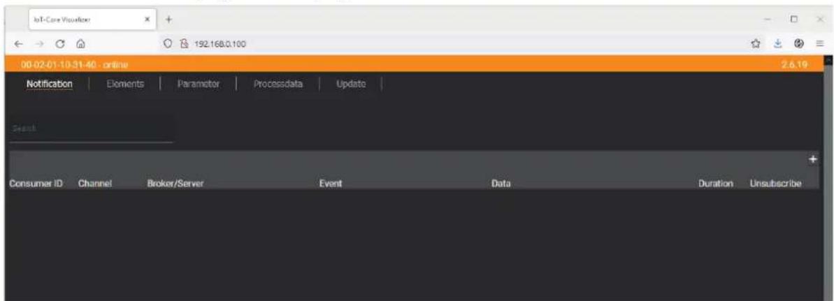
The navigation menu gives the user access to the following functions:
• [Notification]: no function
• [Elements]: Search for elements in the device description (→ 38)
• [Parameter]: Configure the device (→ 38)
- [Processdata]: Access process data (→ 38)
- [Update]: Update firmware (→ 39)
9.2.14.2 Search for elements in the device description
The [Elements] menu page allows you to search the device description for elements with specific properties (type, profile, name) and to output the results.
Requirements:
√ The ifm IoT Core Visualizer has been started.
▶ Click on [Elements].
The menu page to search for elements appears.
▷ The input mask appears.
▶ Select the search criteria of the required element in the selection lists identifier, profile and type.
▶ Click on [Search for ...].
The ifm IoT Core Visualizer searches the device description for elements with the selected search criteria.
The result list shows all elements found.
9.2.14.3 Configure the device
The [Parameter] menu page allows you to configure the device.
Requirements:
√ The ifm IoT Core Visualizer has been started.
▶ Click on [Parameter].
The menu page displays the available parameters of the device.
▷ Current parameter values are displayed.
▶ Navigate to the desired parameter.
▶ Change the parameter value.
▶ Click on, to save the changes.
The changed parameter value is written to the device.
The changed parameter value is active.
▶ Optional: Repeat the procedure to change further parameter values.
▷ The device has been configured.
9.2.14.4 Access process data
The [Processdata] menu page makes it possible to read and write the process data of the device and the connected sensors.
Requirements:
√ The ifm IoT Core Visualizer has been started.
▶ Click on [Processdata].
▷ Menu page shows the substructures of the device description that contains the process data.
The current process values are displayed.
▶ Optional: Activate the [Polling] option and change the update interval.
The process values will be updated with the set interval.
▶ Optional: Click on ○ next to an element to manually update the process value.
To change the value of a process date:
▶ Navigate to the required process date.
▶ Change the process value.
▶ Click on, to save the changes.
The changed process value is written to the device.
The changed process value is active.
9.2.14.5 Update firmware
The [Update] menu page allows you to update the firmware of the device:
Requirements:
√ The ifm IoT Core Visualizer has been started.
▶ Click on [Update].
The menu page displays information about the current firmware version.
▶ Click on [Load software file] and select a new firmware file (*.bin).
▶ Click on [Update] to start the update process.
The firmware of the device is updated.
The area shows the progress of the update process.
▶ After successful update: The device reboots automatically.
9.3 EtherNet/IP
9.3.1 Register the EDS file
To map the device in an EtherNet/IP projection software, ifm provides an EDS file. The device description file contains identification information, supported parameters, process data and fieldbus objects. The user can download the EDS file via documentation.ifm.com.
To add the device to the device catalogue:
▶ Download EDS file of the device.
▶ Start the EtherNet/IP projection software "RSLogix 5000".
▶ Select [Tools] > [EDS Hardware Installation Tool].
▶ Register the downloaded EDS file using the wizard.
The device is added to the device catalogue of the EtherNet/IP projection software.
The EtherNet/IP projection software can access the device functions and data.
9.3.2 Integrate the device into the EtherNet/IP project
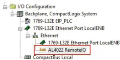
The device is integrated into the project as an Ethernet module.
Requirements:
√ The EDS file of the device is installed correctly.
▶ Start RSLogix 5000.
▶ Create a new EtherNet/IP project or open an existing one.
▶ Add the required components (e.g. PLC, IO scanner) to the automation network and configure them.
In [Controller Organizer]: Open the folder [I/O Configuration].
▶ Right-click on the node [Ethernet].
The context menu appears.
▶ In the context menu, select [New module...].
The module selection dialogue appears.
▶ Select the device in the catalogue and click on [Create].
The [New Module]dialogue window appears.
▶ Enter the name and IP address and confirm with [OK].
The device has been integrated in the EtherNet/IP project.
Example:
9.3.3 Set connection types
The connection types determine the type and scope of the available parameters and process data of the device.
Supported connection types:
| Connection type Configuration | assembly Input assembly Output assembly | |
| Exclusive owner Instance 198 Instance 102 Instance 150 | ||
| Input only Instance 199 Instance 101 Instance 193 (empty) | ||
| Listen only Instance 199 Instance 101 Instance 192 (empty) | ||
Detailed information on the Assembly Objects:

If an "Exclusive owner" connection exists between the IO scanner and the device, the device will switch to the "Implicit protection mode".
In the "Implicit protection mode", acyclic access to the CIP object "Identity Object" and its functions (e.g. reset device) is not possible. Any access attempts will be denied with the error message Device state conflict (0x10).
To set the connection type:
Requirements:
√ Device is integrated in EtherNet/IP project.
In [Controller Organizer]: Double-click on the device node.
The device configuration dialogue appears.
▶ Click on [Change...].
The [Module Definition] dialogue appears.
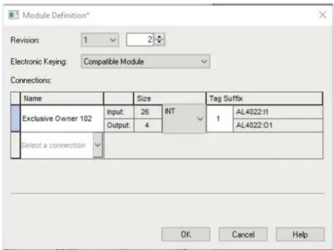
▶ Select the required connection type from the list [Connections].
▶ If necessary, set the data type to [INT].
▶ Click on [OK] to acknowledge the input.
Based on the selected connection type, RSLogix 5000 generates the controller tags of the device (Configuration, Input, Output).
9.3.4 Configure input filters

▶ Observe the notes on input filters: Digital input filters ( ☐ 8)
The filters of the digital inputs can be configured via the following objects:
- Configuration Assembly (Instance 198) (→ ☐ 52)
- Configuration Assembly (Instance 199) ( □55)
These is a separate configuration area for each input filter.
Available parameters per input filter:
- debounce time
- hold time
- hold level
- signal inversion
Requirements:
√ Device is integrated in EtherNet/IP project.
√ Connection type [Exclusive Owner] or [Inputs only] is set.
In [Controller Organizer], select the device folder.
▶ Select [Controller Tags].
▷ [Controller Tags] displays the configuration of the device (DeviceName.C:Data).
▶ Set the parameters.
The input filters have been configured.
9.3.5 Configure counters

▶ Observe the notes on counter modules: Counters ( ☐ 10)
The counter modules can be configured via the following objects:
- Configuration Assembly (Instance 198) ( 52)
These is a separate configuration area for each counter module.
Available parameters per counter module:
- Operating mode of the counter module
• threshold CT of the main counter
• threshold CTb of the batch counter
• function of pin 2 of the port - instance for selecting the counting direction (only with CTDIR operating mode)
Requirements:
√ Device is integrated in EtherNet/IP project.
√ Connection type [Exclusive Owner] is set.
In [Controller Organizer], select the device folder.
▶ Select [Controller Tags].
▷ [Controller Tags] contains the configuration data of the device (DeviceName.C:Data).
▶ Set the parameters.
The counter modules are configured.
9.3.6 Read process data of the ports
The process data of the digital inputs are transmitted in the following objects:
- Input Assembly (Instance 101) ( 56)
- Input Assembly (Instance 102) (→ □ 57)
Available data:
• Signal level of the input channels (after filtering)
• Status of the voltage supply
Requirements:
√ Device is integrated in EtherNet/IP project.
√ The input filters have been configured.
√ Connection type [Exclusive Owner], [Inputs only] or [Listen only] is set.
In [Controller Organizer], select the device folder.
▶ Select [Controller Tags].
▷ [Controller Tags] contains the input data of the device (Devicename.I:Data).
▶ Link process data to variables.
The process values of the digital inputs are available in the application.
9.3.7 Read counter values and counter events
The process data of the counter modules are transmitted in the following objects:
- Input Assembly (Instance 102) ( ☐ 57)
Available parameters (per counter module): - Current main counter value
- Current batch counter value
- Display of batch counter overflow/underflow event
Requirements:
√ Device is integrated in EtherNet/IP project.
√ The counter modules are configured.
√ Connection type [Exclusive Owner] is set.
In [Controller Organizer], select the device folder.
▶ Select [Controller Tags].
▷ [Controller Tags] contains the input data of the device (DeviceName.I:Data).
▶ Link process data to variables.
The process values of the counter modules are available in the application.
9.3.8 Control counters
The counter modules of the ports can be controlled separately. The following control signals are available per counter:
- Reset counter module
- Disable counter module
- Set counting direction (only for CTUD counter operating mode)
- Reset overflow/underflow events
The control signals for resetting the counters and overflow/underflow flags are transmitted in the following object:
- Output Assembly (Instance 150) ( ☐ 58)
To control the counter modules:
Requirements:
√ Device is integrated in EtherNet/IP project.
√ The counter modules are configured.
√ Connection type [Exclusive Owner] is set.
▶ In [Controller Organizer], select the device folder.
▶ Select [Controller Tags].
▷ [Controller Tags] displays the output data of the device (DeviceName.0:Data).
▶ Link control signals of the counter modules with variables.
The counters can be controlled via the application.
9.3.9 Acyclic access
The user can access identification and diagnostic information as well as configuration and process data acyclically via the CIP object classes.
The device supports the following CIP objects:
| Class Code Name Description | |
| 0x01 Identity Object | Identity Object (Class Code: 0x01) ( ☐ 60) |
| 0x02 Message Router Object | Message Router Object (Class Code: 0x02) ( ☐ 62) |
| 0x04 Assembly Object | Assembly Object (Class Code: 0x04) ( ☐ 63) |
| 0x06 Connection Manager Object | Connection Manager Object (Class Code: 0x06) ( ☐ 64) |
| 0x109 LLDP Management Object | LLDP Management Object (Class Code: 0x109) ( ☐ 69) |
| 0x47 Device Level Ring Object | Device Level Ring Object (Class Code: 0x47) ( ☐ 65) |
| 0x48 Quality Of Service Object | Quality Of Service Object (Class Code: 0x48) ( ☐ 66) |
| 0x81 Input Filter Object | Input Filter Object (Class Code: 0x81) ( ☐ 67) |
| 0x82 Counter Object | Counter Object (Class Code: 0x82) ( ☐ 68) |
| 0xF5 TCP/IP Object | TCP/IP Object (Class Code: 0xF5) ( ☐ 70) |
| 0xF6 Ethernet Link Object | Ethernet Link Object (Class Code: 0xF6) ( ☐ 72) |
9.3.9.1 Notes on acyclic access
For acyclic sending and receiving of data, EtherNet/IP applications use the Message (MSG) command.
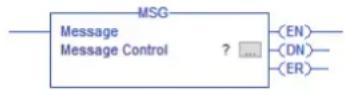

For detailed information about the Message (MSG) command: → user documentation of the EtherNet/IP projection software
10 Maintenance, repair and disposal
The operation of the unit is maintenance-free.
▶ Dispose of the device in an environmentally friendly way in accordance with the applicable national regulations when it is no longer used.
10.1 Cleaning
▶ Disconnect the unit from the voltage supply.
▶ Clean the device from dirt using a soft, chemically untreated and dry cloth.
▶ In case of severe soiling, use a damp cloth.

▶ Do not use any caustic cleaning agents for this!
10.2 Update firmware
The system software of the device can be updated using the following options:
- IoT-Core Visualizer
- IoT-Core REST API
11 Appendix
11.1 ifm IoT Core
11.1.1 Profiles
| Profile Description | |
| blob Binary Large Object | |
| deviceinfo Identification information of a device | |
| devicetag Device-specific identification | |
| devicereset Restart and reset to factory settings | |
| network Network | |
| parameter Parameter | |
| processdata Process data | |
| service Service | |
| software Software | |
| software/uploadablesoftware | Upgradeable software |
11.1.2 Types
| Type Description | |
| structure Structural element (e.g. a folder in the file system) | |
| service Service that can be addressed from the network | |
| event An event that can be started by the firmware and sends messages. | |
| data Data point | |
| device | Root element a device represents |
11.1.3 Services
11.1.3.1 Service: factoryreset
Name: factoryreset
Description: The service sets the parameters of the device to the factory settings.
Request ("data" field): none
Return ("data" field): none
11.1.3.2 Service: force\_counter\_values
Name: force_counter_values
Description: The service writes the values of the main counter and batch counter. The service can only be executed if there is no connection to the fieldbus controller.
Request ("data" field):
| Parameter | Mandatory field | Data type | Description |
| maincounter_value | Optional | INT | Main counter target value |
| Parameter | Mandatory field | Data type Description |
| batchcounter_value | Optional INT Batch | counter target value |
Return ("data" field): none
11.1.3.3 Service: getblobdata
Name: getblobdata
Description: The service reads a Binary Large Object (blob).
Request ("data" field):
| Data field | Mandatory field | Data type Description |
| pos mandatory NUMBER | ER Byte position | |
| length mandatory NUMBER | Size of the object (number of bytes) |
Return ("data" field):
| Data field | Mandatory field | Data type Description |
| data mandatory STRING data to be decoded (BASE64 coded) | ||
| crc optional HEX STRING CRC of the data after decoding | ||
| md5 optional HEX STRING MD5 checked sum of the data after decoding | ||
11.1.3.4 Service: getdata
Name: getdata
Description: The service reads the value of a data point and outputs it.
Request ("data" field): none
Return data ("data" field):
| Parameter | Mandatory field | Data type Description |
| value mandatory | STRING | Value of the data point |
11.1.3.5 Service: getdatamulti
Name: getdatamulti
Description: The service sequentially reads the values of several data points and provides them. The value and the diagnostic code are provided for each data point.
Request ("data" field):
| Data field | Mandatory field | Data type Description |
| datatosend | mandatory ARRAY OF STRINGS | List of data points to be requested; Data points must support the getdata service ("datatosend":["url1", "url2", ..., "urlx"]) |
Return ("data" field):
| Data field | Mandatory field | Data type Description |
| url | mandatory STRING Data point request | |
| code | mandatory INT | Diagnostic code of the request |
| data mandatory STRING Value of the data point | ||
11.1.3.6 Service: getelementinfo
Name: getelementinfo
Description: The service reads the properties of an element of the IoT tree.
Request ("data" field):
| Parameter | Mandatory field | Data type Description |
| adr mandatory STRING | URL of the element whose properties are to be changed | |
Return ("data" field):
| Parameter | Mandatory field | Data type Description | |
| identifier mandatory STRING Identifier of the element | |||
| type mandatory STRING Type of the element | |||
| format optional JSON object Format of the data or of the service content | |||
| uid optional STRING | |||
| profiles optional JSON-AR- | RAY | Element profiles | |
| hash optional STRING | |||
11.1.3.7 Service: getidentity
Name: getidentity
Description: The service reads device information and outputs it.
Request (field „data“): none
Response (field „data“):
| Parameter | Mandatory field | Data type Description |
| iot device Device description as JSON | object | |
| iot.name | mandatory STRING | Type of the element |
| iot.uid | optional STRING | |
| iot.version | mandatory STRING | |
| iot.catalogue | optional ARRAY OF OBJECTS | |
| iot.deviceclass | optional ARRAY OF STRING | Device class |
| iot.serverlist | optional ARRAY OF OBJECTS | |
| device | optional | |
| device.serialnumber | optional | |
| device.hwrevision | optional | |
| device.swrevision | optional | |
| device.custom | optional | |
11.1.3.8 Service: gettree
Name: gettree
Description: The service reads the device description of the IO-Link master and outputs it as a JSON object. The output can be limited to a subtree of the device description.
Request ("data" field):
| Parameter | Mandatory field | Data type Description |
| adr Optional STRING | Root element of the subtree | |
| level Optional STRING | Max. level up to which the subtree is outputno entry: all levels will be displayed0: do not display sub-elements (“subs”)1: display sub-elements2: display sub-elements up to the 2nd level3: display sub-elements up to the 3rd level...20: display sub-elements up to the 20th level |
Return ("data" field)
| Parameter | Mandatory field | Data type Description |
| identifier Mandatory STRING Identifier of the root element | ||
| type Mandatory STRING Type of the element | ||
| format Optional JSON object Format of the data content | ||
| uid Optional STRING | ||
| profiles Optional JSON array | ||
| subs Mandatory JSON array Sub-elements | ||
| hash | Optional STRING | |
| adr Mandatory STRING Root element of the subtree | ||
11.1.3.9 Service: install
Name: install
Description: The service installs the firmware stored in a memory area of the unit.
Request ("data" field): none
Return ("data" field): none
11.1.3.10 Service: querytree
Name: querytree
Description: The service searches a device tree for the criteria profile, type and name and outputs a list with the URLs of the elements found. At least one of the search criteria must be specified. The service can only be executed on the root node of the machine.
Request ("data" field):
| Parameter | Mandatory field | Data type Description |
| profile | optional | STRING Profile of the searched element |
| type optional | STRING Type of | the searched element |
| name | optional | STRING Type of the searched element |
Return ("data" field):
| Parameter | Mandatory field | Data type Description | |
| urlList | mandatory | ARRAY | Array with URLs of the found elements; URLs are separated by commas |
11.1.3.11 Service: reboot
Name: reboot
Description: The service reboots the device.
Request ("data" field): none
Return ("data" field): none
11.1.3.12 Service: setblock
Name: setblock
Description: The service simultaneously sets the values of several data points of a structure.
Request ("data" field):
| Parameter | Mandatory field | Data type Description | |
| datatoset mandatory | ARRAY OF | OBJECTS | List of data points and their new values; Data points must support the setdata service |
| consistent optional | BOOL IO-Link subindex of the parameter | ||
Return ("data" field): none
11.1.3.13 Service: setdata
Name: setdata
Description: The service sets the value of the data point.
Request ("data" field):
| Parameter | Mandatory field | Data type Description |
| newvalue mandatory | STRING New value of the data point | |
| duration optional STRING Duration of value storage | lifetime: Value is saved with IoT Core; Value remains valid even after restart of the deviceuptime: Value is saved until the next restart of the device | |
Return ("data" field): none
11.1.3.14 Service: signal
Name: signal
Description: The service triggers the flashing of the status LEDs of the unit.
Request ("data" field): none
Return ("data" field): none
11.1.3.15 Service: start\_stream\_set
Name: start_stream_set
Description: The service starts the sequential transmission of several data fragments.
Request ("data" field):
| Parameter | Mandatory field | Data type Description |
| size mandatory STRING | Overal length of the data to be transmitted (number of bytes) | |
Return ("data" field): none
11.1.3.16 Service: stream\_set
Name: stream_set
Description: The service transfers a data segment.
Request ("data" field):
| Parameter | Mandatory field | Data type Description |
| value mandatory BIN | (BASE64) Segment of the binary data (BASE64-coded) |
Return ("data" field): none
11.2 EtherNet/IP
11.2.1 Parameters
11.2.1.1 Configuration Assembly (Instance 198)
| Byte | Bit | |||||||
| 7 6 5 4 | 3 2 1 0 | |||||||
| 0 X01_DI1_Pin4_InvertInput | ||||||||
| 1 X01_DI1_Pin4_HoldLevel | ||||||||
| 2...3 X01_DI1_Pin4_DebounceTime | ||||||||
| 4...5 X01_DI1_Pin4_HoldTime | ||||||||
| 6...11 | X01_DI2_Pin2: filter settings (structure → bytes 0...5) | |||||||
| 12...17 | X02_DI1_Pin 4: filter settings (structure → bytes 0...5) | |||||||
| 18...23 | X02_DI2_Pin2: filter settings (structure → bytes 0...5) | |||||||
| 24...29 | X03_DI1_Pin4: filter settings (structure → bytes 0...5) | |||||||
| 30...35 | X03_DI2_Pin2: filter settings (structure → bytes 0...5) | |||||||
| 36...41 | X04_DI1_Pin4: filter settings (structure → bytes 0...5) | |||||||
| 42...47 | X04_DI2_Pin2: filter settings (structure → bytes 0...5) | |||||||
| 48...53 | X05_DI1_Pin4: filter settings (structure → bytes 0...5) | |||||||
| 54...59 | X05_DI2_Pin2: filter settings (structure → bytes 0...5) | |||||||
| 60...65 | X06_DI1_Pin4: filter settings (structure → bytes 0...5) | |||||||
| 66...71 | X06_DI2_Pin2: filter settings (structure → bytes 0...5) | |||||||
| 72...77 | X07_DI1_Pin4: filter settings (structure → bytes 0...5) | |||||||
| 78...83 | X07_DI2_Pin2: filter settings (structure → bytes 0...5) | |||||||
| 84...89 | X08_DI1_Pin4: filter settings (structure → bytes 0...5) | |||||||
| 90...95 | X08_DI2_Pin2: filter settings (structure → bytes 0...5) | |||||||
| 96 | X1 CounterSettings (→ Mapping: Counter settings □ 54) | |||||||
| 97...100 X1_MainThreshold | ||||||||
| 101...102 X1_BatchThreshold | ||||||||
| 103 | X2 CounterSettings (→ Mapping: Counter settings □ 54) | |||||||
| 104...107 X2_MainThreshold | ||||||||
| 108...109 X2_BatchThreshold | ||||||||
| 110 | X3 CounterSettings (→ Mapping: Counter settings □ 54) | |||||||
| 111...114 X3_MainThreshold | ||||||||
| 115...116 X3_BatchThreshold | ||||||||
| 117 | X4 CounterSettings (→ Mapping: Counter settings □ 54) | |||||||
| 118...121 X4_MainThreshold | ||||||||
| 122...123 X4_BatchThreshold | ||||||||
| 124 | X5 CounterSettings (→ Mapping: Counter settings □ 54) | |||||||
| 125...128 X5_MainThreshold | ||||||||
| 129...130 X5_BatchThreshold | ||||||||
| 131 | X6 CounterSettings (→ Mapping: Counter settings □ 54) | |||||||
| 132...135 X6_MainThreshold | ||||||||
| 136...137 X6_BatchThreshold | ||||||||
| Byte | Bit | ||||||||
| 7 6 5 | 4 3 2 1 0 | ||||||||
| 138 | X7 CounterSettings (→ Mapping: Counter settings ↗ 54) | ||||||||
| 139...142 X7 MainThreshold | |||||||||
| 143...144 X7 BatchThreshold | |||||||||
| 145 | X8 CounterSettings (→ Mapping: Counter settings ↗ 54) | ||||||||
| 146...149 X8 MainThreshold | |||||||||
| 150...151 X8 BatchThreshold | |||||||||
Legend:
- InvertInput Signal inversion 1 byte • 0x00: do not invert (default)
- 0x01: invert
- HoldLevel Signal level to be maintained 1 byte • 0x00: LOW
- 0x01: HIGH (default)
- DebounceTime Debounce time (value in *0.1 ms)
2 bytes · 0x0000: 0 ms (default)
Debounce time = 0x0123
...
- Debounce time[0] = 0x01
- 0x01F4: 50 ms
- Debounce time[1] = 0x23
- HoldTime Hold time (value in *0.1 ms)
2 bytes • 0x0000: 0 ms (default)
Hold time = 0x1234
...
- Hold time[0] = 0x12
- 0xEA60: 6000 ms
- Hold time[1] = 0x34
- MainThreshold Threshold CT of the main counter
- MainThreshold[0] = 0x67
- BatchThreshold Threshold CTb of the batch counter
2 bytes · 0x0001: 1
BatchThreshold = 0x0123
...
- BatchThreshold[0] = 0x01
- 0xFFFF: 65535 (default)
- BatchThreshold[1] = 0x23
Mapping: Counter settings
| Byte(offset) | Bit | |||||||
| 7 6 5 4 | 3 2 1 0 | |||||||
| n Counter Direction Selection | Pin2 Function res. Counter Mode | |||||||
Legend:
- Counter Mode Operating mode of the counter module 3 bits • 0x0: CTU – up counter (default)
- 0x1: CTD - down counter
- 0x2: CTUD – up and down counter
- 0x3: CTDIR – up or down counter
- Pin2 Function Pin 2 function of the port 3 bits • 0x0: N/C – no function (default)
- 0x1: Counter Edge Input 2 – counting input
- 0x2: Count direction – select counting direction
- 0x3: Reset Main + Batch Counter - reset counters
- 0x4: Disable Main + Batch Counter – disable counters
- Counter Direction Instance for selecting the counting direction 1 bit • 0x0: Pin 2 (default) Selection • 0x1: F
- 0x1: PLC
11.2.1.2 Configuration Assembly (Instance 199)
| Byte | Bit | |||||||
| 7 6 5 4 | 3 2 1 0 | |||||||
| 0 X01_DI1_Pin4_InvertInput | ||||||||
| 1 X01_DI1_Pin4_HoldLevel | ||||||||
| 2...3 X01_DI1_Pin4_DebounceTime | ||||||||
| 4...5 X01_DI1_Pin4_HoldTime | ||||||||
| 6...11 | X01_DI2_Pin2: filter settings (structure → bytes 0...5) | |||||||
| 12...17 | X02_DI1_Pin 4: filter settings (structure → bytes 0...5) | |||||||
| 18...23 | X02_DI2_Pin2: filter settings (structure → bytes 0...5) | |||||||
| 24...29 | X03_DI1_Pin4: filter settings (structure → bytes 0...5) | |||||||
| 30...35 | X03_DI2_Pin2: filter settings (structure → bytes 0...5) | |||||||
| 36...41 | X04_DI1_Pin4: filter settings (structure → bytes 0...5) | |||||||
| 42...47 | X04_DI2_Pin2: filter settings (structure → bytes 0...5) | |||||||
| 48...53 | X05_DI1_Pin4: filter settings (structure → bytes 0...5) | |||||||
| 54...59 | X05_DI2_Pin2: filter settings (structure → bytes 0...5) | |||||||
| 60...65 | X06_DI1_Pin4: filter settings (structure → bytes 0...5) | |||||||
| 66...71 | X06_DI2_Pin2: filter settings (structure → bytes 0...5) | |||||||
| 72...77 | X07_DI1_Pin4: filter settings (structure → bytes 0...5) | |||||||
| 78...83 | X07_DI2_Pin2: filter settings (structure → bytes 0...5) | |||||||
| 84...89 | X08_DI1_Pin4: filter settings (structure → bytes 0...5) | |||||||
| 90...95 | X08_DI2_Pin2: filter settings (structure → bytes 0...5) | |||||||
Legend:
- InvertInput Signal inversion 1 byte • 0x00: do not invert (default)
- 0x01: invert
- HoldLevel Signal level to be maintained 1 byte • 0x00: LOW
- 0x01: HIGH (default)
- DebounceTime Debounce time (value in *0.1 ms)
2 bytes • 0x0000: 0 ms (default)
Debounce time = 0x0123
...
- Debounce time[0] = 0x01
- 0x01F4: 50 ms
- Debounce time[1] = 0x23
- HoldTime Hold time (value in *0.1 ms)
2 bytes • 0x0000: 0 ms (default)
Hold time = 0x1234
...
- Hold time[0] = 0x12
- 0xEA60: 6000 ms
- Hold time[1] = 0x34
11.2.2 Cyclic data
11.2.2.1 Input Assembly (Instance 101)
| Byte (off-set) | Bit | |||||||
| 7 6 5 4 | 3 2 1 0 | |||||||
| 0 res. res. res. res. res. res. res. res. res. res. res. res. res. res. res. res. res. res. res. res. res. res. res. res. res. res. res. res. res. res. res. res. res. res. res. res. res. res. res. res. res. res. res. res. res. res. res. res. res. res. res, res. res. res. res. res. res. res. res. res. res. res. res. res. res. res. res. res. res. res. res. res. res. res. res. res. res. res. res. res. res. res. res. res. res. res. res. res. res. res. res. res. res. res. res. res. res. res. res. res. res 1 res. res. res. res. res. res. res. res. res. res. res. res. res. res. res. res. res. res. res. res. res. res. res. res. res. res. res. res. res. res. res. res. res. res. res. res. res. res. res. res. res. res. res. res. res. res. res. res. res. res . 2 X04: DI2 X04: DI1 X03: DI2 X03: DI1 X02: DI2 X02: DI1 X01: DI2 X01: DI1 3 X08: DI2 X08: DI1 X07: DI2 X07: DI1 X06: DI2 X06: DI1 X05: DI2 X05: DI1 | ||||||||
Legend:
- SENS PWR Status of the device voltage supply 1 bit • 0x0: no error
- 0x1: error
- DI1 Signal level digital input at pin 4 of the port (after filtering)
1 bit • 0x0: LOW
- 0x1: HIGH
- DI2 Signal level digital input at pin 2 of the port (after filtering)
1 bit • 0x0: LOW
- 0x1: HIGH
11.2.2.2 Input Assembly (Instance 102)
| Byte (off-set) | Bit | |||||||
| 7 6 5 4 | 3 2 1 0 | |||||||
| 0 X08: | OV/UV X07: | OV/UV X06: | OV/UV X05: | OV/UV X04: | OV/UV X03: | OV/UV | X02: | OV/UV X01: |
| 1 res. res. res. res. res. res. res. | NS PWR | |||||||
| 2 X04: | DI2 X04: | DI1 X03: | DI2 X03: | DI1 X02: | DI2 X02: | DI1 X01: | DI2 X01: | DI1 |
| 3 X08: | DI2 X08: | DI1 X07: | DI2 X07: | DI1 X06: | DI2 X06: | DI1 X05: | DI2 X05: | DI1 |
| 4...7 X01: | Main Counter Value | |||||||
| 8...9 X01: | Batch Counter Value | |||||||
| 10...13 X02: | Main Counter Value | |||||||
| 14...15 X02: | Batch Counter Value | |||||||
| 16...19 X03: | Main Counter Value | |||||||
| 20...21 X03: | Batch Counter Value | |||||||
| 22...25 X04: | Main Counter Value | |||||||
| 26...27 X04: | Batch Counter Value | |||||||
| 28...31 X05: | Main Counter Value | |||||||
| 32...33 X05: | Batch Counter Value | |||||||
| 34...37 X06: | Main Counter Value | |||||||
| 38...39 X06: | Batch Counter Value | |||||||
| 40...43 X07: | Main Counter Value | |||||||
| 44...45 X07: | Batch Counter Value | |||||||
| 46...49 X08: | Main Counter Value | |||||||
| 50...51 X08: | Batch Counter Value | |||||||
Legend:
| • OV/UV | Overflow/underflow occurred at batch counter | 1 bit | • 0x0: no event• 0x1: overflow/underflow event |
| • SENS PWR | Status of the device voltage supply | 1 bit | • 0x0: no error• 0x1: error |
| • DI1 | Signal level digital input at pin 4 of the port (after filtering) | 1 bit | • 0x0: LOW• 0x1: HIGH |
| • DI2 | Signal level digital input at pin 2 of the port (after filtering) | 1 bit | • 0x0: LOW• 0x1: HIGH |
| • Main Counter Value | Current main counter value of the port | 4 bytes | • 0x0000 0000: 0...• 0xFFFF FFFE: 4294967294 |
| • Batch Counter Value | Current batch counter value of the port | 2 bytes | • 0x0000: 0...• 0xFFFE: 65534 |
11.2.2.3 Output Assembly (Instance 150)
| Byte | Bit | |||||||
| 7 6 5 4 | 3 2 1 0 | |||||||
| 0 Reserved X01: Reset | Counter Event | X01: Count Direction | X01: Disable Counter | X01: Reset Counter | ||||
| 1 Reserved X02: Reset | Counter Event | X02: Count Direction | X02: Disable Counter | X02: Reset Counter | ||||
| 2 Reserved X03: Reset | Counter Event | X03: Count Direction | X03: Disable Counter | X03: Reset Counter | ||||
| 3 Reserved X04: Reset | Counter Event | X04: Count Direction | X04: Disable Counter | X04: Reset Counter | ||||
| 4 Reserved X05: Reset | Counter Event | X05: Count Direction | X05: Disable Counter | X05: Reset Counter | ||||
| 5 Reserved X06: Reset | Counter Event | X06: Count Direction | X06: Disable Counter | X06: Reset Counter | ||||
| 6 Reserved X07: Reset | Counter Event | X07: Count Direction | X07: Disable Counter | X07: Reset Counter | ||||
| 7 Reserved X08: Reset | Counter Event | X08: Count Direction | X08: Disable Counter | X08: Reset Counter | ||||
Legend:
- Reset Counter Reset main counter and batch counter to initial value 1 bit • 0x0: no action
- 0x1: reset main + batch counter and counter events to overflow/underflow
- Disable Counter Disable main counter & batch counter 1 bit • 0x0: no action
- 0x1: disable main and batch counter
- Count Direction Set counting direction (valid only for counter mode CTDIR)
1 bit · 0x0: up
- 0x1: down
- Reset Counter Event Reset overflow/underflow counter events 1 bit • 0x0: no action
- 0x1: reset counter events
11.2.3 Acyclical data
11.2.3.1 CIP class and instance services
Supported class and instance services:
| Service code | Name Description | |
| 0x01 | Get Attribute All Read all attributes | |
| 0x02 | Set Attribute All Write all attributes | |
| 0x05 | Reset Reset | |
| 0x09 | Delete Delete | |
| 0x0E | Get Attribute Single Read single attribute | |
| 0x10 | Set Attribute Single Write single attribute | |
| 0x18 | Get Member Read member of an instance attribute | |
| 0x4B | Flash LEDs Flash device LEDs (identification) | |
| 0x4E | Forward Close Close connection | |
| 0x54 | Forward Open Open new connection |
11.2.3.2 CIP object classes
Supported object classes:
| Class Code Name Description | ||
| 0x01 Identity Object | Identity Object (Class Code: 0x01) (→ □ 60) | |
| 0x02 Message | Router Object | Message Router Object (Class Code: 0x02) (→ □ 62) |
| 0x04 Assembly | Object | Assembly Object (Class Code: 0x04) (→ □ 63) |
| 0x06 Connection Manager Object | Connection Manager Object (Class Code: 0x06) (→ □ 64) | |
| 0x47 Device Level Ring Object | Device Level Ring Object (Class Code: 0x47) (→ □ 65) | |
| 0x48 Quality Of Service Object | Quality Of Service Object (Class Code: 0x48) (→ □ 66) | |
| 0x81 Input Filter Object | Input Filter Object (Class Code: 0x81) (→ □ 67) | |
| 0x82 Counter Object | Counter Object (Class Code: 0x82) (→ □ 68) | |
| 0xF5 | TCP/IP Object | TCP/IP Object (Class Code: 0xF5) (→ □ 70) |
| 0xF6 | Ethernet Link Object | Ethernet Link Object (Class Code: 0xF6) (→ □ 72) |
| 0x109 | LLDP Management Object | LLDP Management Object (Class Code: 0x109) (→ □ 69) |
11.2.3.3 Identity Object (Class Code: 0x01)
Class attributes
| Attr. ID Access Name Data type Description Value | |||||
| 1 Get Revision UINT Revision | of the object 2 | ||||
| 2 Get Max. Instance UINT Max. number of instances of the object 1 | |||||
| 3 Get Number of instances UINT Number of instances of the object 1 | |||||
| 6 Get Max. ID Number Class | Attributes | UINT Max. ID | number of a class attribute 7 | ||
| 7 Get Max. ID Number In- | stance Attributes | UINT Max. ID | number of the instance attribute 19 | ||
Instance attributes
| Attr. ID | Access | Name | Data type | Description | Default |
| 1 Get Vendor | ID | UINT Manufacturer | ID | 0x322 | |
| 2 Get Device | Type | UINT Device type | 0x12 | ||
| 3 Get Product Code | UINT Product code of the device | 4022 | |||
| 4 Get Revision | STRUCT Revision of | 1.1 | |||
| • Major Revision | USINT | Main revision (1...127) | 1 | ||
| • Minor Revision | USINT | Side revision (3 digits, if necessary with zeros in the beginning) | 001 | ||
| 5 Get Status | WORD Overall status of the device | ||||
| 6 | Get | Serial number | UDINT | Serial number of the device | -- |
| 7 Get Product Name | SHORT | STRING | Product name of the device | ETH Module SL EIP 16DI IP67 | |
| 8 Get State | USINT State of the device (State machine)0: Nonexistent1: Device Self Testing2: Standby3: Operational4: Major Recoverable Fault6-254: Reserved255: Default for “Get_Attributes_All” service | ||||
| 19 | Get | Protection Mode | UINT | Current protection mode of the device | 0 |
Services
| Code | Service | Class | Instance | Description |
| 0x01 | Get Attribute All | Yes | Yes | Read all attributes |
| 0x05 | Reset | Yes | Yes | Reset |
| 0x4B | Flash LEDs | No | Yes | Flash device LEDs (identification) |
| 0x0E | Get Attribute Single | Yes | Yes | Read single attribute |
| 0x10 | Set Attribute Single | Yes | Yes | Write single attribute |
If an Identity Object receives a reset request, it carries out the following actions:
- It checks if it supports the requested reset type.
• It responds to the request.
• It tries to execute the requested reset type.
Supported reset types:
- 0: reboot the device (mandatory for all EtherNet/IP devices).
• 1: restore factory settings and reboot the device.
11.2.3.4 Message Router Object (Class Code: 0x02)
Class attributes
| Attr. ID Access Name Data type Description Value | ||||
| 1 Get Revision UINT Revision of the object 1 | ||||
| 2 Get Max. Instance UINT Max. number of instances of the object 1 | ||||
| 3 Get Number of instances UINT Number of instances 1 | ||||
| 6 Get Max. ID Number Class Attributes | UINT Max. ID number of a class attribute 7 | |||
| 7 Get Max. ID Number Instance Attributes | UINT Max. ID number of the instance attribute 0 | |||
Instance attributes
The object class has no instance attributes.
Services
| Code | Service | Class | Instance | Description |
| 0x0E | Get Attribute Single | Yes | Yes | Read single attribute |
| 0x10 | Set Attribute Single | No | Yes | Write single attribute |
11.2.3.5 Assembly Object (Class Code: 0x04)
Class attributes
| Attr. ID Access Name Data type Description Value | |||||
| 1 Get Revision UINT Revision of the object 2 | |||||
| 2 Get Max. Instance UINT Max. number of instances of the object 0x00C7 | |||||
| 3 Get Number of instances UINT Number of instances 5 | |||||
| 6 Get Max. ID Number Class At-tributes | UINT Max. ID number of the class attribute 7 | ||||
| 7 Get Max. ID Number Instance Attributes | UINT Max. ID number of the instance attribute 4 | ||||
Instance attributes
| Attr. ID Access Name Data type Description | Default | ||||
| 1 | Get | Number of Members | UINT | Number of members in list | -- |
| 2 | Get | Member | UINT | List of members | -- |
| 3 | Get / Set | Data | UINT | Current process data image | -- |
| 4 | Get | Size | UINT | Process data length (number of bytes) | -- |
The following object instances are available:
- Configuration Assembly (Instance 198) (→ □ 52)
- Configuration Assembly (Instance 199) (→ □ 55)
• Input Assembly (Instance 101) (→ □ 56)
• Input Assembly (Instance 102) (→ □ 57)
• Output Assembly (Instance 150) (→ □ 58)
Services
| Code | Service | Class | Instance | Description |
| 0x0E | Get Attribute Single | Yes | Yes | Read single attribute |
| 0x10 | Set Attribute Single | No | Yes | Write single attribute |
| 0x18 | Get Member | No | Yes | Read member of an instance attribute |
11.2.3.6 Connection Manager Object (Class Code: 0x06)
Class attributes
| Attr. ID Access Name Data type Description Value | ||||
| 1 Get Revision UINT Revision of the object 1 | ||||
| 2 Get Max. Instance UINT Max. number of instances of the object 1 | ||||
| 3 Get Number of instances UINT Number of instances 3 | ||||
| 6 Get Max. ID Number Class Attributes | UINT Max. ID number of a class attribute 7 | |||
| 7 Get Max. ID Number Instance Attributes | UINT Max. ID number of the instance attribute 0 | |||
Instance attributes
The object class has no instance attributes.
Services
| Code | Service | Class | Instance | Description |
| 0x0E | Get Attribute Single | Yes | Yes | Read single attribute |
| 0x10 | Set Attribute Single | No | Yes | Write single attribute |
| 0x54 | Forward Open No Yes | Open new connection | ||
| 0x4E | Forward Close | No | Yes | Close connection |
11.2.3.7 Device Level Ring Object (Class Code: 0x47)
Class attributes
| Attr. ID Access Name Data type Description Value | ||||
| 1 Get Revision UINT Revision of the object 3 | ||||
| 2 Get Max. Instance UINT Max. number of instances of the object 1 | ||||
| 3 Get Number of instances UINT Number of instances of the object 1 | ||||
| 6 Get Max. ID Number Class Attributes | UINT Max. ID | number of the class attribute 7 | ||
| 7 Get Max. ID Number Instance Attributes | UINT Max. ID | number of the instance attribute 12 | ||
Instance attributes
| Attr. ID | Access | Name | Data type | Description | Default |
| 1 | Get | Network topology | USINT | Current network topology• 0: linear | 0 |
| 2 | Get | Network status | USINT | Current network status• 0: OK | 0 |
| 10 | Get | Active Supervisor | STRUCT of UDINT, ARRAY(6) of USINT | IP and/or MAC address of the active supervisor | 0 |
| 12 | Get | Capability Flags | DWORD | DLR capability of the device• 0x82: Beacon based Ring Node, Flush Table Frame support | 0x82 |
Services
| Code Service | Class | Instance | Description |
| 0x01 | Get Attribute All | No | Yes Read all attributes |
| 0x0E | Get Attribute Single | Yes | Yes Read single attribute |
11.2.3.8 Quality Of Service Object (Class Code: 0x48)
Class attributes
| Attr. ID Access Name Data type Description Value | ||||
| 1 Get Revision UINT Revision of the object 1 | ||||
| 2 Get Max. Instance UINT Max. number of instances of the object 1 | ||||
| 3 Get Number of instances UINT Number of instances of the object 1 | ||||
| 6 Get Max. ID Number Class Attributes | UINT Max. ID | number of a class attribute 7 | ||
| 7 Get Max. ID Number Instance Attributes | UINT Max. ID | number of the instance attribute 8 | ||
Instance attributes
| Attr. ID | Access | Name | Data type | Description | Default |
| 2 | Get / Set | DSCP PTP Event | USINT | DSCP value for PTP event frames | 59 |
| 3 | Get / Set | DSCP PTP General | USINT | DSCP value for PTP general frames | 47 |
| 4 | Get / Set | DSCP PTP Urgent | USINT | DSCP value for implicit messages with “urgent” priority | 55 |
| 5 | Get / Set | DSCP Scheduled | USINT | DSCP value for implicit messages with “scheduled” priority | 47 |
| 6 | Get / Set | DSCP High | USINT | DSCP value for implicit messages with “high” priority | 43 |
| 7 | Get / Set | DSCP Low | USINT | DSCP value for implicit messages with “low” priority | 31 |
| 8 | Get / Set | DSCP Explicit | USINT | DSCP value for explicit messages with “scheduled” priority | 27 |
Services
| Code Service | Class | Instance | Description |
| 0x0E | Get Attribute Single | Yes | Read single attribute |
| 0x10 | Set Attribute Single | No | Write single attribute |
11.2.3.9 Input Filter Object (Class Code: 0x81)
Class attributes
| Attr. ID Access Name Data type Description Value | ||||
| 1 Get Revision UINT Revision of the object 1 | ||||
| 2 Get Max. Instance UINT Max. number of instances of the object 16 | ||||
| 6 Get Max. ID Number Class Attributes | UINT Max. ID number of a class attribute 7 | |||
| 7 Get Max. ID Number Instance Attributes | UINT Max. ID number of the instance attribute 4 | |||
Instance attributes
| Attr. ID | Access | Name | Data type | Description | Default |
| 1 | Get / Set | Input Inverter | USINT | Signal inversion• 0: no signal inversion• 1: signal inversion | 0 |
| 2 | Get / Set | Hold Level | USINT | Signal level to be maintained• 0: LOW• 1: HIGH | 1 |
| 3 Get / Set | Debounce | Time UINT Debounce time | • 0: 0 ms...• 500: 50 ms | 0 | |
| 4 Get / Set | Hold Time | UINT Hold time | • 0: 0 ms...• 60000: 6000 ms | 0 | |
Services
| Code Service | Class | Instance | Description |
| 0x01 | Get Attribute All | No | Yes Read all attributes |
| 0x0E | Get Attribute Single | Yes | Yes Read single attribute |
| 0x10 | Set Attribute Single | No | Yes Write single attribute |
11.2.3.10 Counter Object (Class Code: 0x82)
Class attributes
| Attr. ID Access Name Data type Description Value | ||||
| 1 Get Revision UINT Revision of the object 1 | ||||
| 2 Get Max. Instance UINT Max. number of instances of the object 8 | ||||
| 6 Get Max. ID Number Class Attributes | UINT Max. ID number of a class attribute 7 | |||
| 7 Get Max. ID Number Instance Attributes | UINT Max. ID number of the instance attribute 6 | |||
Instance attributes
| Attr. ID | Access | Name | Data type | Description | Default |
| 1 Get / Set | Counter Mode | UINT Operating mode of the | counter module0x0: CTU – up counter0x1: CTD – down counter0x2: CTUD – up and down counter0x3: CTDIR – up or down counter | 0x0 | |
| 2 Get / Set | Pin 2 function | UINT | Pin 2 function of the | port0x0: N/C – no function0x1: counter transition input 2 – counting input ^1 0x2: count direction ^2 0x3: reset Main + Batch Counter – reset counters0x4: disable Main + Batch Counter – disable counters | 0x0 |
| 3 Get / Set | Count Direction Selection | USINT | Instance for selecting the counting direction0x0: Pin 20x1: Fieldbus PLC | 0x0 | |
| 4 | Get / Set | Main Threshold | UDINT | Threshold of the main counter0x0000 0001: 1...0xFFFF FFFF: 4294967295 | 0x1 |
| 5 Get / Set | Batch Threshold | UINT Threshold of the batch | counter0x0001: 1...0xFFFF: 65535 | 0x1 | |
| 6 | Set | Force Counter | 6xUSINT | Write values of the counter modules | |
^1 only valid if Counter Mode = CTUD
^2 only valid if Counter Mode = CTDIR
Services
| Code Service | Class | Instance | Description |
| 0x01 | Get Attribute All | No | Yes Read all attributes |
| 0x0E | Get Attribute Single | Yes | Yes Read single attribute |
| 0x10 | Set Attribute Single | No | Yes Write single attribute |
11.2.3.11 LLDP Management Object (Class Code: 0x109)
Class attributes
| Attr. ID Access Name Data type Description Value | ||||
| 1 Get Revision UINT Revision of the object 1 | ||||
| 2 Get Max. Instance UINT Max. number of instances of the object 1 | ||||
| 3 Get Number of instances UINT Number of instances of the object 1 | ||||
| 6 Get Max. ID Number Class Attributes | UINT Max. ID | number of a class attribute 7 | ||
| 7 Get Max. ID Number Instance Attributes | UINT Max. ID | number of the instance attribute 5 | ||
Instance attributes
| Attr. ID | Access | Name | Data type | Description | Default |
| 1 Get / Set | LLDP Enable | UINT Enable | / disable LLDP | 0: disabled1: enabled for all ports | 1 |
| 2 | Get / Set | msgTxInterval | UINT | Interval for transmission of LLDP frames (in seconds) | 30 |
| 3 | Get / Set | msgTxHold | USINT | Interval time multiplier, factor for determining the hold time for transmission to adjacent devicese.g. 4: 4x interval time | 4 |
| 4 Get LLDP | Datastore | UINT Supported methods for querying | the LL-DP database0x02: SNMP | 0x02 | |
| 5 | Get / Set | Last Change | DWORD | Time since last change in local LLDP database (in seconds) | 0 |
Services
| Code | Service | Class | Instance | Description |
| 0x0E | Get Attribute Single | Yes | Yes | Read single attribute |
| 0x10 | Set Attribute Single | No | Yes | Write single attribute |
11.2.3.12 TCP/IP Object (Class Code: 0xF5)
Class attributes
| Attr. ID Access Name Data type Description Value | |||||
| 1 Get Revision UINT Revision of the object 4 | |||||
| 2 Get Max. Instance UINT Max. number of instances of the object 1 | |||||
| 3 Get Number of instances UINT Number of instances of the object 1 | |||||
| 6 Get Max. ID Number Class Attributes | UINT Max. ID number of a class attribute 7 | ||||
| 7 Get Max. ID Number Instance Attribute | UINT Max. ID number of the instance attribute 14 | ||||
Instance attributes
| Attr. ID | Access | Name | Data type | Description | Default |
| 1 Get Status | UINT Status of the TCP | IP interface0: interface not configured1: interface configured with DHCP, BOOTP or non-volatile memory | |||
| 2 Get Configuration Capability DWORD Configuration options for | interfaceBit 0: BOOTP ClientBit 2: DHCP ClientBit 4: configuration adjustableBit 7: ACD-capable | 0x95 | |||
| 3 | Get / Set | Configuration Control | DWORD | Configuration controlBit 0..3: startup configuration0: statically assigned IP address1: configuration via BOOTP2: configuration via DHCP | 0 |
| 4 | Get | Physical Link Object Path | STRUCT of | Logical path to the physical communication interface (Ethernet link object) | |
| Path Size | UINT | Length (number of words, little endian format) | 0x02 00 | ||
| Path | Padded EPATH | Class ID: 0xF6 (Ethernet Link Object)Instance ID: 0x1 | 0x20 F6 24 01 | ||
| 5 | Get / Set | Interface configuration | STRUCT of | TCP/IP interface configuration | |
| IP Address | UDINT | IP address | 192.168.1.250 | ||
| Network Mask | UDINT | Network mask | 255.255.255.0 | ||
| Gateway Address | UDINT | Gateway address | 0.0.0.0 | ||
| Name Server | UDINT | Primary name server | 0.0.0.0 | ||
| Name Server 2 | UDINT | Secondary name server | 0.0.0.0 | ||
| Domain Name | STRING | Default domain name | 0 | ||
| 6 Get / Set | Host Name | STRING | Host name | 0: not configured | 0 |
| 8 Get TTL Value | UINT TTL value | 1 | |||
| 9 | Get / Set | Mcast Config | UINT | Mcast configuration | 0 |
| 10 | Get / Set | SelectAcd | BOOL | ACD activation/deactivation0: deactivated1: activated | 1 |
| 11 | Get / Set | Last conflict detected | STRUCT of | Last conflict detected | 0 |
| Attr. ID Access Name Data type Description Default | |||||
| 11 Get / Set | • AcdActivity | USINT Condition of ACD activity at last conflict | detected• 0: Noconflictdetected• 1: Probelpv4Address• 2: Ongoing Detection• 3: SemiActiveprobe | ||
| • Remote MAC ARRAY(6) | of USINT | MAC address of the remote node of the ARP PDU in which the conflict was detected | |||
| • ArpPdu ARRAY(28) | of USINT | Copy of the data of the ARP PDU in which the conflict was detected | |||
| 13 Get / Set | Encapsulation | Inactivity Time-out | UINT Inactivity | before the TCP connection is deactivated (in seconds) | 120 |
| 14 Get IANA | Port Admin | UINT IANA port administrator configuration | • 0x0: tcp: 44818• 0x1: udp: 44818• 0x2: udp: 2222 | 0 | |
Services
| Code Service | Class | Instance | Description |
| 0x01 | Get Attribute All | No | Yes |
| 0x0E | Get Attribute Single | Yes | Yes |
| 0x10 | Set Attribute Single | No | Yes |
11.2.3.13 Ethernet Link Object (Class Code: 0xF6)
Class attributes
| Attr. ID Access Name Data type Description Value | ||||
| 1 Get Revision UINT Revision of the object 4 | ||||
| 2 Get Max. Instance UINT Max. number of instances of the object 2 | ||||
| 3 Get Number of instances UINT Number of instances 2 | ||||
| 6 Get Max. ID Number Class Attributes | UINT Max. ID number of a class attribute 7 | |||
| 7 Get Max. ID Number Instance Attribute | UINT Max. ID number of the instance attribute 768 | |||
Instance attributes
| Attr. ID | Access | Name | Data type | Description | Default |
| 1 | Get | Interface Speed | UDINT | Current transmission rate• 10: 10 Mbits/s• 100: 100 Mbits/s | 100 |
| 2 | Get | Interface Status Flag | DWORD | Interface status flags• Bit 0: link status• Bit 1: half/full duplex• Bit 2...4: negotiation status• Bit 5: manual change requires reset• Bit 6: local hardware error• Bit 7...31: Reserved | 0x20 |
| 3 Get | Physical Address | ARRAY(6) | of USINT | MAC address | |
| 4 Get | Interface Counters | STRUCT(1) | 1) of UDINT | Interface-specific counter | |
| 5 Get | Media Counters | STRUCT(1) | 2) of UDINT | Medium-specific counter | |
| 6 | Get / Set | Interface Control | STRUCT of | Interface control | |
| • Interface Settings | DWORD | SettingsBit 0:• 0: auto-negotiation on• 1: auto-negotiation offBit 1:• 0: half duplex• 1: full duplex | 0 | ||
| • Interface Speed | UINT | Transmission rate• 10: 10 Mbits/s• 100: 100 Mbits/s | |||
| 7 Get | Interface type | USINT | 0: unknown | 1: internal interface2: twisted pair3: optical fibre | 2 |
| 8 | Get | Interface State | USINT | Current status of the interface• 0: unknown• 1: active; ready for transmission and reception• 2: not active• 3: test mode | 0 |
| Attr. ID Access Name Data type Description Default | |||||
| 9 Get / Set Admin State USINT Control of the access to the | interface• 1: activate• 2: deactivate | 1 | |||
| 10 Get Interface Label SHORT_STRI | NG | Interface identifier • X21 | (instance 1)• X22 (instance 2) | ||
| 11 Get Interface Capability | STRUCT of Interface capability | ||||
| • Interface Speed | DWORD | Transmission rate• 10: 10 Mbits/s• 100: 100 Mbits/s | |||
| • Interface Duplex Mode | DWORD | Duplex mode• HD: half duplex• FD: full duplex | |||
| 768 | Get / Set MDIX | USINT MDIX configuration | 1 | ||
Services
| Code | Service | Class | Instance | Description |
| 0x01 | Get Attribute All | No | Yes | Read all attributes |
| 0x0E | Get Attribute Single | Yes | Yes | Read single attribute |
| 0x10 | Set Attribute Single | No | Yes | Write single attribute |
- Contents
- Preliminary note
- Safety instructions
- Cyber security
- ATTENTION
- Intended use
- Function
- Visual indication
- Parameter setting
- Inputs
- Sensor supply
- Digital input filters
- Debouncing
- Holding
- Inverting
- Filter combination
- Counters
- Counter mode CTU
- Counter mode CTD
- Behaviour:
- Counter mode CTUD
- Counter mode CTDIR
- EtherNet/IP
- Installation
- Install device
- Electrical connection
- Overview
- General wiring information
- Connection technology
- Ethernet
- Process connections
- Voltage supply
- Derating behaviour
- Operating and display elements
- LEDs
- Status
- Ethernet
- Voltage supply
- Process connections
- Set-up
- Settings
- Parameter setting software
- Supported parameter setting software
- Getting started
- Configure the EtherNet/IP interface
- Fieldbus: Read the interface configuration
- Fieldbus: Read the connection status
- Ports: Configure input filters
- Ports: Read digital input data
- Counters: Configure counter modules
- Requirements:
- Counters: Read counter values
- Counters: Control counter modules
- Gateway: Read identification information
- Gateway: Read status and diagnostic information
- Gateway: Set the application tag
- Firmware: Read firmware version
- Firmware: Reset the device
- Firmware: Restart the device
- ifm IoT Core
- ifm IoT Core: General information
- Accessing the ifm IoT Core
- GET method
- Example: GET request
- POST method
- Example: POST request
- Getting started
- Notes on configuration
- General functions
- Example: Outputting the subtree
- Example: Reading several elements sequentially
- Example: Changing a parameter value
- Fieldbus: Read the interface configuration
- Ports: Configure input filters
- Ports: Read digital input data
- Counters: Configure counter modules
- Counters: Control counters
- Counters: Read and write counter values
- Example: Write counter values
- Gateway: Read device information
- Gateway: Read status and diagnostic information
- Gateway: Set the application tag
- Gateway: Update firmware
- IoT-Core Visualizer
- Start the ifm IoT Core Visualizer
- Search for elements in the device description
- Configure the device
- Access process data
- Update firmware
- EtherNet/IP
- Register the EDS file
- Integrate the device into the EtherNet/IP project
- Set connection types
- Configure input filters
- Configure counters
- Read process data of the ports
- Available data:
- Read counter values and counter events
- Control counters
- Acyclic access
- Notes on acyclic access
- Maintenance, repair and disposal
- Cleaning
- Update firmware
- Appendix
- ifm IoT Core
- Profiles
- Types
- Services
- Service: factoryreset
- Service: force\_counter\_values
- Service: getblobdata
- Service: getdata
- Service: getdatamulti
- Service: getelementinfo
- Service: getidentity
- Service: gettree
- Service: install
- Service: querytree
- Service: reboot
- Service: setblock
- Service: setdata
- Service: signal
- Service: start\_stream\_set
- Service: stream\_set
- EtherNet/IP
- Parameters
- Legend:
- Configuration Assembly (Instance 199)
- Cyclic data
- Input Assembly (Instance 101)
- Acyclical data
- CIP class and instance services
- CIP object classes
- Identity Object (Class Code: 0x01)
- Message Router Object (Class Code: 0x02)
- Instance attributes
- Assembly Object (Class Code: 0x04)
- Connection Manager Object (Class Code: 0x06)
- Device Level Ring Object (Class Code: 0x47)
- Quality Of Service Object (Class Code: 0x48)
- Input Filter Object (Class Code: 0x81)
- Counter Object (Class Code: 0x82)
- LLDP Management Object (Class Code: 0x109)
- TCP/IP Object (Class Code: 0xF5)
- Ethernet Link Object (Class Code: 0xF6)
Brand : IFM
Model : AL4022
Category : Input/output module