
PY2006 - Sensor IFM - Free user manual and instructions
Find the device manual for free PY2006 IFM in PDF.


| Product Type | Electronic Pressure Sensor |
| Brand | IFM |
| Model | PY2006 |
| Measuring Range | -125...2500 mbar (-1.82...36.26 psi) |
| Maximum Permissible Pressure | 20000 mbar (290 psi) |
| Bursting Pressure | 50 bar (725 psi) |
| Output 1 | IO-Link (process data) |
| Output 2 | Analogue 4...20 mA |
| Operating Modes | 2-wire, 3-wire |
| Power Supply | SELV/PELV, typically 18...30 V DC |
| Process Connection | G1 Aseptoflex Vario |
| Pressure Type | Relative pressure |
| Vacuum Resistance | Yes |
| Scalable Measuring Range | Yes (up to 20% of final value) |
| Damping Settings | Analogue output (dAA) and process data (dAP) |
| Zero-Point Calibration | Via teach button (E30425) |
| IO-Link Communication | Yes (IODD available at ifm.com) |
| Protection Class | IP rating not specified, but hygienic design |
| Hygienic Compliance | 3A, EHEDG (with suitable adapters) |
| Ventilation Diaphragm | GORE diaphragm with protective cover |
| Replaceable Filter Cover | Yes (several versions available) |
| Torque for Process Connection | 35 Nm (G1 Aseptoflex Vario) |
| Operating Temperature | Not specified (refer to data sheet) |
| Maintenance | Clean ventilation diaphragm with lime-deficient water |
Frequently Asked Questions - PY2006 IFM
User questions about PY2006 IFM
0 question about this device. Answer the ones you know or ask your own.
Ask a new question about this device
Download the instructions for your Sensor in PDF format for free! Find your manual PY2006 - IFM and take your electronic device back in hand. On this page are published all the documents necessary for the use of your device. PY2006 by IFM.
USER MANUAL PY2006 IFM
Operating instructions Electronic pressure sensor
PY200x
UK
80283564 / 00 09 / 2019
natural_image
Line drawing of a cylindrical mechanical component with a flanged top and base (no text or symbols)Contents
1 Preliminary note....3
1.1 Symbols used .... 3
2 Safety instructions ....3
3 Functions and features .... 4
3.1 Applications ....4
4 Function....5
4.1 IO-Link 5
4.2 Set-up via IO-Link....5
4.3 Scalable measuring range....6
4.4 Process data via IO-Link 6
4.5 Defined state in case of a fault 6
4.6 Operating modes....6
4.6.1 2-wire operation....6
4.6.2 3-wire operation....6
4.7 Analogue function 7
5 Installation....7
5.1 G1A Aseptoflex Vario adaptation (PM17xx)......8
5.2 Use in hygienic areas to 3A....10
5.3 Use in hygienic areas to EHEDG 10
5.4 Ventilation diaphragm with protective cover 11
5.4.1 Function ventilation diaphragm.... 11
5.4.2 Orientation of the filter cover 12
5.5 Filter cover....12
6 Electrical connection....14
7 Parameter setting 15
7.1 Parameter setting via PC....15
7.2 Parameter setting via the memory plug....16
7.3 Teach offset with the teach button 16
7.3.1 Scale analogue value 17
7.3.2 Select the standard unit of measurement (option)....17
7.4 User settings (optional)....17
7.4.1 Set damping for the analogue output 17
7.4.2 Set damping for the switching signal....17
7.4.3 Zero-point calibration....18
7.5 List of the parameters....18
8 Operation....18
1 Preliminary note
1.1 Symbols used
▶ Instruction
Reaction, result
[...] Designation of keys, buttons or indications
→ Cross-reference

Important note
Non-compliance may result in malfunction or interference

Information
Supplementary note
2 Safety instructions
- The device described is a subcomponent for integration into a system.
- The manufacturer is responsible for the safety of the system.
-
The system manufacturer undertakes to perform a risk assessment and to create a documentation in accordance with legal and normative requirements to be provided to the operator and user of the system. This documentation must contain all necessary information and safety instructions for the operator, the user and, if applicable, for any service personnel authorised by the manufacturer of the system.
-
Read this document before setting up the product and keep it during the entire service life.
- The product must be suitable for the corresponding applications and environmental conditions without any restrictions.
- Only use the product for its intended purpose (→ Functions and features).

- Only use the product for permissible media (→ Technical data).
- If the operating instructions or the technical data are not adhered to, personal injury and/or damage to property may occur.
- The manufacturer assumes no liability or warranty for any consequences caused by tampering with the product or incorrect use by the operator.
- Installation, electrical connection, set-up, operation and maintenance of the product must be carried out by qualified personnel authorised by the machine operator.
- Protect units and cables against damage.
3 Functions and features
The unit measures and monitors the system pressure of machines and installations.
2 outputs are available:
- OUT1: Measured pressure value via IO-Link.
More information 4.1 and 7.
- OUT2: Analogue signal proportional to pressure 4...20 mA
3.1 Applications
Type of pressure: relative pressure
| Order number | Measuring range | Pressure rating (max. permissible pressure) *) | Bursting pressure | |||
| Pressure sensors with G1 Aseptoflex Vario | ||||||
| mbar psi | mbar psi bar psi | |||||
| PY2007 | -50...1000 | -0.73...14.5 | 10000 | 145 | 30 | 435 |
| PY2006 | -125...2500 | -1.82...36.26 | 20000 | 290 | 50 | 725 |
| *) With static overload pressure. | ||||||
| MPa = (measured value in bar) ÷ 10 kPa = (measured value in bar) x 100 | ||||||

Avoid static and dynamic overpressure exceeding the indicated pressure rating by taking appropriate measures.
The indicated bursting pressure must not be exceeded.
Even if the bursting pressure is exceeded only for a short time, the unit may be destroyed.
ATTENTION: Risk of injury!

Not suitable for systems that have to meet the criteria of E1.2 / 63-03 of the 3A standard 63-03.

The units are vacuum resistant.

4 Function
The unit converts the system pressure into an analogue output signal (4...20 mA). Moreover, it provides the process data via IO-Link.
4.1 IO-Link
The device has an IO-Link communication interface which requires an IO-Link capable module (IO-Link master).
The IO-Link interface enables direct access to the process and diagnostic data and provides the possibility to set the parameters of the unit during operation.
In addition, communication is possible via a point-to-point connection with a USB adapter cable.
The IODDs necessary for the configuration of the unit, detailed information about process data structure, diagnostic information, parameter addresses and the necessary information about the required IO-Link hardware and software can be found at www.ifm.com.
4.2 Set-up via IO-Link
The device parameters can be set via IO-Link:
- The device parameters are set via the IO-Link interface ( 4.1 and 7).
- All settings can also be carried out before installation of the unit.
4.3 Scalable measuring range
The measuring range can be scaled to up to 20% of the final value of the measuring range:
- Setting the parameter [ASP2] defines at which measured value the output signal is 4 mA.
- Setting the parameter [AEP2] defines at which measured value the output signal is 20mA.
4.4 Process data via IO-Link
All process data is available via IO-Link:
- The unit is designed for fully bidirectional communication.
• The following options are available: - Remote display: read and display the current system pressure.
- Remote parameter setting: read and change the current parameters via IO-Link parameter setting ( 4.1)
4.5 Defined state in case of a fault
- If a fault is detected, the analogue output passes into a defined state (= 21.5mA) .

In case of a fault indication (= 21.5 mA)
▶ Read parameters via IO-Link or contact the manufacturer
4.6 Operating modes
The operating mode is defined by the wiring ( 6 electrical connection) and automatically recognised by the unit.
4.6.1 2-wire operation
OUT2 (pin 2) Analogue signal proportional to pressure 4...20 mA
4.6.2 3-wire operation
OUT1 (pin 4) Communication via IO-Link OUT2 (pin 2) Analogue signal proportional to pressure 4...20 mA
4.7 Analogue function
OUT2 is an analogue output:
Minimum distance between [ASP2] and [AEP2] = 20 % of the measuring span.
Factory setting Measuring range scaled
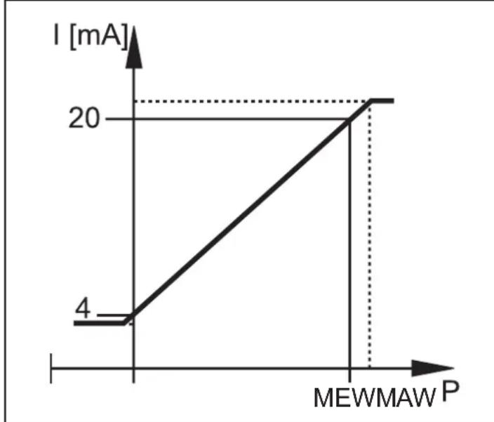
line
| MEWMAW P | I [mA] | | -------- | ------ | | Low | 4 | | High | 20 |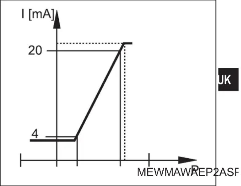
line
| MEWMAW/REP2ASF | I [mA] | | -------------- | ------ | | Start | 4 | | Peak | 20 |P = System pressure
MAW = Initial value of the measuring range
ASP2 = Analogue start point [ASP2]
MEW = Final value of the measuring range
AEP2 = Analogue end point [AEP2]
In the set measuring range, the output signal range is between 4 and 20 mA.
It is also indicated:
- System pressure above [AEP2]: 20...20.5 mA
- System pressure below [ASP2]: 4...3.8 mA
• Fault indication according to Namur: 21.5 mA
5 Installation

▶ Before installing and removing the unit make sure that no pressure is applied to the system and there is no medium in the pipe.
▶ Note dangers related to external system / medium temperatures.
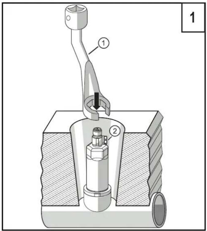
▶ In case of a recessed sensor installation, please use an open ring spanner or a hexagon socket with the corresponding inside contour.


▶ During sensor installation, do not exert any axial leverage with the tool (1) on the rotatable filter cover (2) ( fig. 1).

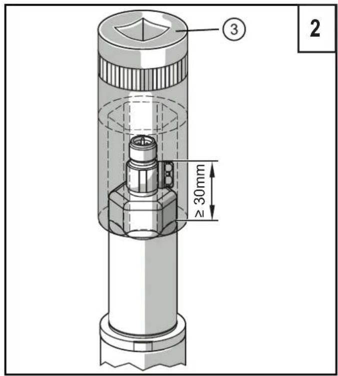
In case of installation by means of a hexagon socket (3), make sure that the tool's spanner flat has an inner height of at least 30 mm ( fig. 2). Align the rotatable filter cover so that it is flush with one of the spanner flats.
▶ Insert the unit in a process connection.
▶ Tighten firmly. Recommended tightening torque:
| Process connection Tightening torque in Nm | |
| G1A Aseptoflex Vario 35 | |
| Depends on the sealing type, the pressure load and the lubrication! | |

A zero-point calibration of the measured value is possible via the teach function ( 7.3 Teach offset with the teach button)
5.1 G1A Aseptoflex Vario adaptation (PM17xx)
▶ Insert the unit with process adapter into the process connection and tighten using a spanner.

Information about available adapters at www.ifm.com.
▶ Observe the instructions of the adapter.
▶ Use a lubricating paste which is suitable and approved for the application.
The unit can be fixed to different process connections.
Options are as follows:
| 1 | Installation using an adapter with sealing ring (hygiene-compliant) |
| Order no. E332xx / E333xx.To meet the hygiene regulations use a process adapter with leakage port.The adapters are supplied with EPDM O-ring (order no. E30054).More sealing rings are available as accessories:FKM O-ring (order no. E30123)PEEK sealing ring (order no. E30124). The PEEK sealing ring is long-term stable and maintenance-free.When you replace the PEEK sealing ring or change from a PEEK sealing ring to an O-ring, the process adapter also needs to be replaced with a new equivalent adapter. | |
| 2 | Installation using a welding adapter with sealing ring (hygiene-compliant) |
| To meet the hygiene regulations use a process adapter with leakage port.Make sure that the process adapter does not warp during welding. Use welding mandrel E30452.The sealing edge must not be damaged by subsequent surface treatment. (→ instructions in operating instructions of the adapter).The adapter is supplied with EPDM O-ring (order no. E30054). Another sealing ring is available as accessory:FKM O-ring (order no. E30123). | |
| 3 | Installation using a process adapter with metal-to-metal seal |
| Order no. E337xx / E338xxA long-term stable and maintenance-free fitting without bug traps in the metal-to-metal seal is only valid for once-only mounting.If the sealing has to be installed several times, use a new adapter. | |
| 4 | Installation to G 1 flange / G 1 bush |
| The sensor is sealed with the sealing ring at the back of the process connection.► The sealing area at the flange / bush must be flush with the tapped hole and have a surface characteristic of min. Rz = 6.3. |
5.2 Use in hygienic areas to 3A
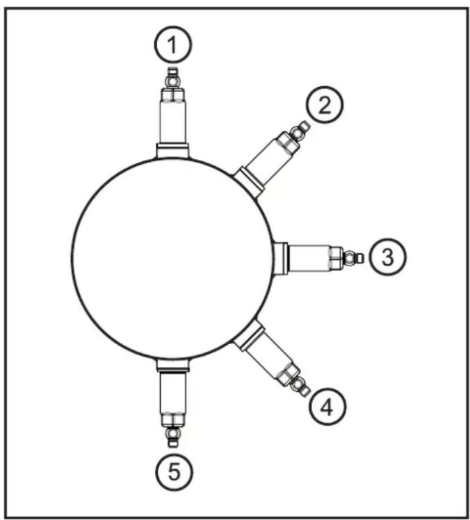
The following applies to units with 3A certification:
▶ Only use adapters with 3A certification for the process connection.
▶ Do not install the unit at the lowest point of the pipe or tank ( position 5) in order that the medium can run off the area of the measuring element.
5.3 Use in hygienic areas to EHEDG

The sensor is suited for CIP (cleaning in place) when installed correctly.
▶ Observe the application limits (temperature and material resistance) according to the data sheet.
▶ Make sure that the sensor is integrated into the system according to EHEDG:
▶ Use self-draining installation.
▶ Only use process adapters permitted according to EHEDG with special seals required by the EHEDG position paper.

The gasket of the system interface must not be in contact with the sealing point of the sensor.
▶ In case of structures in a tank, the installation must be flush mount. If not possible then direct water jet cleaning and cleaning of dead spaces must be possible.
▶ Leakage ports must be clearly visible and must be installed facing downwards for vertical pipes.
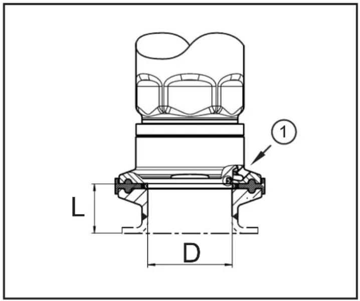
▶ To avoid dead space adhere to the dimensions:
$$ L < (D). $$

1: Leakage port
5.4 Ventilation diaphragm with protective cover
5.4.1 Function ventilation diaphragm
The ventilation diaphragm enables the relative pressure measurement since barometric and temperature-dependent pressure fluctuations between the measuring cell and the environment are compensated for.
The ventilation diaphragm is protected against damage by a screwed cap with circumferential ports.

For a correct functioning of the diaphragm please take the following into account:
▶ Remove soiling and cleaning agents immediately using plenty of lime-deficient splash water.

If the sensor is in a cooling stage:
▶ Avoid contact of the diaphragm with liquids to avoids negative pressure in the measuring system resulting in a slightly falsified measured value and additional strain on the diaphragm.
5.4.2 Orientation of the filter cover
The filter cover is freely rotatable around the sensor's axis and thus adaptable to the environmental conditions.
When the sensor is mounted in a vertical position, the condensate escapes through the ports in the protective cap due to gravity.
When the sensor is mounted in a horizontal position or similar, the filter protection cap must be rotated towards one of the two lateral faces to bring the GORE diaphragm into a vertical position. This guarantees the optimum drainage for liquids.

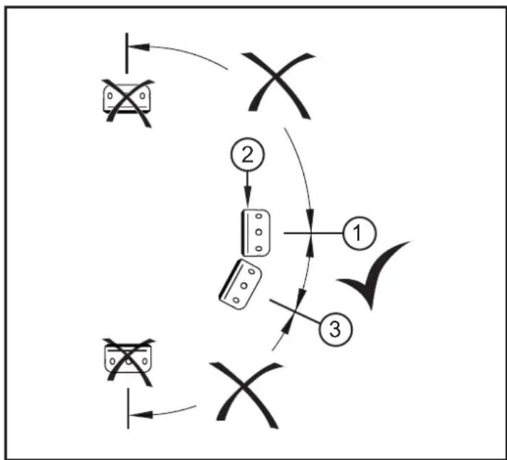
To ensure an optimum function of the pressure compensation element, align the filter cover as shown in fig. 1.
flowchart
graph TD
    A["Step 1"] --> B["Step 2"]
    B --> C["Step 3"]
    C --> D["Step 4"]
    D --> E["End"]
▶ Ideal orientation (1):
Filter cover in horizontal position.
The ventilation diaphragm (2)
in the filter cover is in a vertical position.
▶ Maximum inclination: 30^ (3)
fig. 1: orientation
5.5 Filter cover
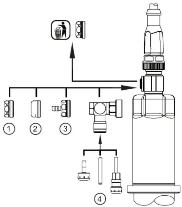
Replace filter cover:
| 1 | Exchange the filter cover incl. GORE diaphragm (E30142). |
| 2 | Replace the filter cover with a closed version (E30148) (*) |
Improve the protection of the filter cover:
| 3 | Replace the filter cover with a version with a tube fitting and a vent tube that ends in a protected and dry area (E30139). |
| 4 | Set of accessories (E30467) with integrated replacement diaphragm (GORE), for high degree of soiling and / or high climate pollution.Function: (→ installation instructions E30467) |

▶ Avoid soiling and moisture during the exchange
▶ Clean the thread carefully and without residues
▶ Do not damage the adhesive area of the sensor
▶ Observe the orientation of the filter cover
(→ installation instructions E30139 / 30467)
flowchart
graph TD
    A["①"] --> B["②"]
    B --> C["③"]
    C --> D["④"]
    D --> E["④"]
    style A fill:#f9f,stroke:#333
    style B fill:#ccf,stroke:#333
    style C fill:#cfc,stroke:#333
    style D fill:#fcc,stroke:#333
    style E fill:#cff,stroke:#333

(*) When using the closed cover cap, there is no pressure compensation of the measuring cell any more. This results in measurement deviations caused by:
• fluctuations of the atmospheric pressure
- pressure fluctuations inside the unit in case of temperature changes ( 10 K ≤ 30 mbar ).
6 Electrical connection

The unit must be connected by a qualified electrician.
The national and international regulations for the installation of electrical equipment must be adhered to.
Voltage supply according to EN 50178, SELV, PELV.
▶ Disconnect power.
▶ Connect the unit as follows:
| Core colours | 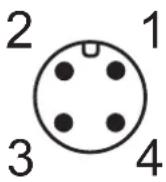 | 2-wire operation (2w) 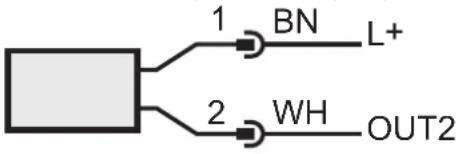 | ||
| 1 BN brown | ||||
| 2 WH white | ||||
| 3 BU blue | ||||
| 4 BK black | ||||
3-wire operation (3w) 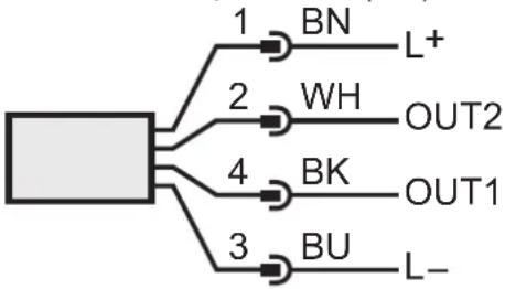 | ||||
| OUT1: communication via IO-Link OUT2: analogue output Colours to DIN EN 60947-5-2 | ||||
| Wiring example | ||||
| (2w) 1 x analogue (3w) 1 x analogue | ||||
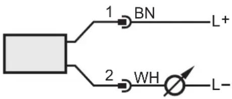 | 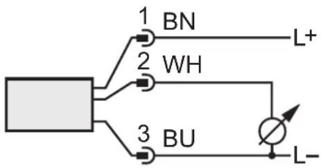 | |||
| (3w) 1 x analogue / 1 x IO-Link (3w) 1 x | IO-Link | |||
 | 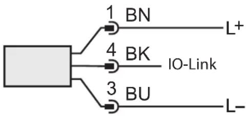 | |||

7 Parameter setting

The unit can be configured via the IO-Link function.
▶ Prepare IO-Link hardware and software for parameter setting.
▶ Connect the unit with e.g. an IO-Link interface ( 7.1) or a programmed memory plug ( 7.2).
▶ Set the parameters.
▶ Put the unit into operation.
The parameters can be set before installation or during operation.

Changing parameters during operation can influence the function of the plant.
▶ Ensure that there will be no malfunctions in your plant.
7.1 Parameter setting via PC
For parameter setting, an IO-Link capable software is necessary (e.g. LINERECORDER DEVICE).
IO-Link interfaces from ifm are available for the connection of the unit via the USB interface of a computer → www.ifm.com.
▶ Prepare computer, software and interface.
▶ Connect the unit with the IO-Link interface.
▶ Follow the menu of the IO-Link software.
▶ Set the parameters.
▶ Put the unit into operation.
Adjustable parameters( 7.5).

7.2 Parameter setting via the memory plug
A parameter set can be written to the unit / can be recorded by the unit via a memory plug (ifm storage module) → www.ifm.com.

In order to allow for data to be written from the memory plug to the sensor, the sensor must have the factory setting.

If the sensor has been configured, the memory plug records the parameter set which can then be transferred to other sensors of the same type.
▶ Load a suitable parameter set (e.g. from a PC or from a sensor of the same type) to the memory plug.
▶ Connect the memory plug between sensor and socket.
Sensor with factory setting: When voltage is supplied, the parameter set is transferred from the memory plug to the sensor.
Sensor with changed settings: When voltage is supplied, the memory plug records the sensor's parameter set.
▶ Remove the memory plug.
▶ Put the unit into operation.
Adjustable parameters ( 7.5).
You can find more information about the memory plug in the corresponding technical documentation → www.ifm.com.
7.3 Teach offset with the teach button
An external teach button (E30425) allows for a zero-point calibration (calibration offset). The current measured value is taken as internal zero point if it lies within a range of +/- 3% of the final value of the measuring range.

For connection information see the E30425 data sheet If a teach button is connected, no IO-Link communication is possible
▶ Integrate the teach button between the installed sensor and the supply cable.
▶ Maintain the plant pressure constantly at zero (configurable range = +/- 3% of the measuring span).
▶ Press the button for > 2 ... < 10 s.
When voltage is supplied, the LED in the button flashes at 2 Hz and configures the zero point (calibration offset).
In case of a fault, the LED flashes at 8 Hz.
7.3.1 Scale analogue value
| ▶ Select [ASP2] and set the value at which 4 mA is provided.▶ Select [AEP2] and set the value at which 20 mA is provided. Minimum distance between ASP2 and AEP2 = 20 % of the measuring span (scaling factor 5). | [ASP2][AEP2] |
7.3.2 Select the standard unit of measurement (option)
| ▶ Select [uni.P] and set the unit of measurement:[bAr] / [mbar] / [MPA] / [kPA] / [PSI] / [mWS] / [inH2O]The selectable units of measurement depend on the respective unit. | [uni] |
7.4 User settings (optional)
7.4.1 Set damping for the analogue output
| ▶ Select [dAA] and set the damping constant (rise time 10...90 %) in seconds. Setting range: 0.000...4.000 s.[IMAGE] Damping [dAA] only influences the analogue output / analogue signal path. | [dAA] |
7.4.2 Set damping for the switching signal
| ▶ Select [dAP] and set the damping constant in seconds (t value 63 %). Setting range: 0.000...4.000 s. | [dAP] |
| Damping [dAP] influences the process data flow (IO-Link communication). |

7.4.3 Zero-point calibration
| ▶ Select[cof]Compared to the real measured value, the internal measured value (operating value of the sensor) is shifted.• Teach range: - 3...+ 3 % of the measuring span. | [cof] |

Setting to zero is made with the command "Teach COF".
[coF] is reset with the command "Reset COF".
7.5 List of the parameters
| Parameter Function | |
| ASP2 | Analogue start pointMeasured value at which 4 mA is provided. |
| AEP2 | Analogue end pointMeasured value at which 20 mA is provided.Minimum distance between ASP and AEP = 20 % of the measuring span. |
| Lo Minimum value memory for system pressure. | |
| Hi Maximum value memory for system pressure. | |
| tcoF | Zero-point calibration (calibration offset)Compared to the real measured value, the internal measured value (operating value of the sensor) is shifted.• Teach range: - 3...+ 3 % of the measuring span. |
| dAA | Damping for the analogue outputPressure peaks of short duration or high frequency can be filtered out using this function. |
| dAP Damping of the process value (only applies to IO-Link evaluation) | |
| uni Standard unit of measurement for system pressure. | |
8 Operation
After power on, the unit is in the Run mode (= normal operating mode). It carries out its measurement and evaluation functions and provides output signals according to the set parameters.
Further technical data

Further technical data and scale drawing at www.ifm.com.
UK
More information at www.ifm.com
- Contents
- Preliminary note
- Symbols used
- Safety instructions
- Functions and features
- Applications
- Function
- IO-Link
- Set-up via IO-Link
- Scalable measuring range
- Process data via IO-Link
- Defined state in case of a fault
- Operating modes
- 2-wire operation
- 3-wire operation
- Analogue function
- Installation
- G1A Aseptoflex Vario adaptation (PM17xx)
- Use in hygienic areas to 3A
- Use in hygienic areas to EHEDG
- Ventilation diaphragm with protective cover
- Function ventilation diaphragm
- Orientation of the filter cover
- Filter cover
- Electrical connection
- Parameter setting
- Parameter setting via PC
- Parameter setting via the memory plug
- Teach offset with the teach button
- Scale analogue value
- Select the standard unit of measurement (option)
- User settings (optional)
- Set damping for the analogue output
- Set damping for the switching signal
- Zero-point calibration
- List of the parameters
- Operation
- Further technical data
Brand : IFM
Model : PY2006
Category : Sensor