
E61439 - Encoder IFM - Free user manual and instructions
Find the device manual for free E61439 IFM in PDF.


| Product Type | Draw-wire mechanism for encoders |
| Intended Use | Conversion of linear movement into rotary movement for distance or displacement measurement and position detection |
| Compatible Encoders | IFM RU3100 series (and others via appropriate coupling) |
| Wire Material | Stainless steel measuring wire |
| Maximum Pull-out Length | Not to be exceeded; refer to product data sheet |
| Installation Orientation | Measuring wire outlet facing downwards to prevent liquid ingress |
| Transport Lock | Remove only just before mounting |
| Wire Guidance | Vertical alignment recommended; avoid bending or sharp edges |
| Mounting Position | Recommended: straight pulling direction; use idler pulley if needed |
| Non-recommended Position | Wire entry facing upwards; wire outlet rotated >3° |
| Environmental Protection | Protect from humidity, chemical liquids, extreme temperatures, vibrations, shocks |
| Care Instructions | Do not oil or grease the measuring wire; avoid squeezing or bending |
| Safety Precautions | Do not open housing; do not let wire snap uncontrolled; ensure machine is stationary |
| Personal Injury Risk | Tensioned wire may cause injury; secure wire to measured object |
| Installation Personnel | Only qualified and authorized personnel |
| Initial Setup | Disconnect power; ensure machine stands still during installation |
| Documents | Full technical data and approvals via QR code or www.ifm.com |
| Manual Language | English (original); translations available on request |
Frequently Asked Questions - E61439 IFM
User questions about E61439 IFM
0 question about this device. Answer the ones you know or ask your own.
Ask a new question about this device
Download the instructions for your Encoder in PDF format for free! Find your manual E61439 - IFM and take your electronic device back in hand. On this page are published all the documents necessary for the use of your device. E61439 by IFM.
USER MANUAL E61439 IFM
Installation instructions Draw-wire mechanism for encoders
UK
80284578/01 06/2022
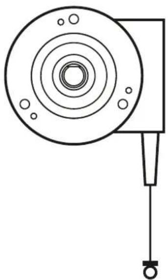
natural_image
Pure technical line drawing of a mechanical component with concentric circles and a vertical rod (no text or symbols)Contents
1 Preliminary note ....3
2 Safety instructions ....3
2.1 Symbols used ....3
3 Functions and features ....4
4 Installation....4
4.1 Generel structure of the device ....5
4.2 Application examples with encoder RU3100 ....5
4.2.1 Installation with draw-wire E61442, E61443 and E61444 ....5
4.2.2 Installation with draw-wire E61440 6
4.2.3 Installation with draw-wire E61441 6
4.2.4 Installation with draw-wire E61439 7
4.3 Installation of the draw-wire mechanism 8
4.4 Draw-wire mechanism 8
4.4.1 Avoid damage to the wire 9
4.5 Wire guide....10
4.6 Special mounting conditions ....10
4.6.1 Recommended mounting position 10
4.6.2 Non recommended installation position 11
1 Preliminary note
You will find instructions, technical data, approvals and further information using the QR code on the unit / packaging or at www.ifm.com.
2 Safety instructions
- The device described is a subcomponent for integration into a system.
- The manufacturer is responsible for the safety of the system.
-
The system manufacturer undertakes to perform a risk assessment and to create a documentation in accordance with legal and normative requirements to be provided to the operator and user of the system. This documentation must contain all necessary information and safety instructions for the operator, the user and, if applicable, for any service personnel authorised by the manufacturer of the system.
-
Read this document before setting up the product and keep it during the entire service life.
- The product must be suitable for the corresponding applications and environmental conditions without any restrictions.
- Only use the product for its intended purpose (→ Functions and features).
- If the operating instructions or the technical data are not adhered to, personal injury and/or damage to property may occur.
- The manufacturer assumes no liability or warranty for any consequences caused by tampering with the product or incorrect use by the operator.
- Installation, electrical connection, set-up, programming, configuration, operation and maintenance of the product must be carried out by personnel qualified and authorised for the respective activity.
- Protect units and cables against damage.
2.1 Symbols used
▶ Instruction
Reaction, result
[...] Designation of keys, buttons or indications
→ Cross-reference

Important note
Non-compliance may result in malfunction or interference.
3 Functions and features
The draw-wire mechanism is installed on an encoder. Via the wire travel, linear movement is converted into rotary movement. The unit is for example used for distance or displacement measurement and for position detection.
4 Installation

This product is a precision measuring device. Therefore it has to be handled with care by trained staff. The following warnings apply to influences outside the limit values indicated in the product data sheet.
▶ Disconnect power.
▶ Ensure that the machine stands still.
▶ Do not start the drive during installation.
▶ Do not hit the shaft; do not use a file or similar tool on the shaft.
Damage to the encoder can be caused by:
• too high forces on the shaft
- humidity and chemical liquids (do not connect any cables oriented upwards)
• extreme temperatures
• too high vibrations and shocks
- short circuit or too high an operating voltage
- impact, shock or any other physical forces
4.1 General structure of the device

1: Encoder
2: Coupling
3: Draw-wire mechanism
4.2 Application examples with encoder RU3100
4.2.1 Installation with draw-wire E61442, E61443 and E61444

natural_image
Technical line drawing of an electric motor assembly showing internal components and exploded view (no text or labels)4.2.2 Installation with draw-wire E61440
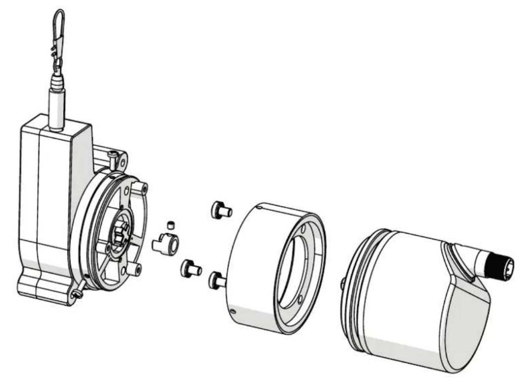
natural_image
Technical line drawing of a mechanical assembly showing exploded and assembled views (no text or symbols)4.2.3 Installation with draw-wire E61441

natural_image
Technical line drawing of a mechanical assembly showing exploded view and assembled view (no text or symbols)4.2.4 Installation with draw-wire E61439

natural_image
Technical line drawing of a mechanical assembly showing exploded and assembled views (no text or symbols)UK
4.3 Installation of the draw-wire mechanism
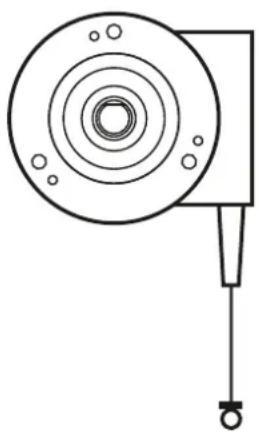
▶ Install the unit so that any damage to or contamination of the measuring wire is prevented.
▶ Install the unit so that the measuring wire outlet faces downwards.
This prevents the penetration of liquids.
natural_image
Pure technical line drawing of a mechanical component with concentric circles and a vertical rod (no text or symbols)4.4 Draw-wire mechanism
▶ Remove the transport lock of the measuring wire only just before mounting.

When using draw-wire mechanisms, ensure that any danger for people or damage to machines is excluded in case of malfunction or a failure of the sensor.
4.4.1 Avoid damage to the wire
▶ Do not squeeze or bend the measuring wire.
▶ Avoid damage to the measuring wire due to sharp edges.
▶ Only draw out the measuring wire using the bracket intended for this purpose (e.g. ring buckle).
▶ Do not oil or grease the measuring wire.

CAUTION!
Non-intended use of the measuring wire may lead to injuries.
▶ Do not open the housing (prestressing of the measuring wire in the housing).
▶ Do not wrap the measuring wire around unprotected parts of bodies.
▶ Do not let the measuring wire snap or contract into the housing without control.
▶ Do not draw out the measuring wire beyond the maximum pull-out length.
▶ Protect the measuring wire against mechanical damage during mounting.
▶ Protect the wire fixture against unintentional release.
4.5 Wire guide

Tensioned measuring wires may present a risk of injury to the operating personnel.
▶ Fix the measuring wire to the measured object.
▶ Wire fixture via ring, thread, eyelet or hook.
▶ Guide the measuring wire vertically.
| For optimum wire guide, mount the wire fixture at the end of the measuring wire so that it can move freely. | 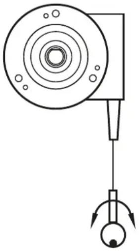 |
4.6 Special mounting conditions
4.6.1 Recommended mounting position
| ▶ If there is a risk of ice formation on the measuring wire, use an idler pulley to break the ice. |  |
| ▶ Ensure a straight pulling direction of the measuring wire. If necessary, use an idler pulley. | 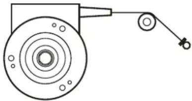 |
4.6.2 Non recommended installation position
| ▶ Do not mount the wire entry facing upwards in order to avoid ingress of water. |   |
| ▶ A wire outlet rotated by >3° will lead to malfunction of the wire rope and significant wear on the wire entry after a short period of operation. | 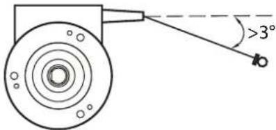 |
- Contents
- Preliminary note
- Safety instructions
- Symbols used
- Functions and features
- Installation
- General structure of the device
- Application examples with encoder RU3100
- Installation with draw-wire E61442, E61443 and E61444
- Installation with draw-wire E61440
- Installation with draw-wire E61441
- Installation with draw-wire E61439
- Installation of the draw-wire mechanism
- Draw-wire mechanism
- Avoid damage to the wire
- CAUTION!
- Wire guide
- Special mounting conditions
- Recommended mounting position
- Non recommended installation position
Brand : IFM
Model : E61439
Category : Encoder