
AL1373 - Processor IFM - Free user manual and instructions
Find the device manual for free AL1373 IFM in PDF.


| Product Type | IO-Link Master with POWERLINK Interface |
| Model | AL1373 |
| Manufacturer | ifm electronic gmbh |
| IO-Link Ports | 8 (Class A) |
| Fieldbus Interface | POWERLINK (Controlled Node) |
| IoT Interface | Ethernet (RJ45 via M12), REST API, MQTT, WebSocket |
| Supply Voltage | 24 V DC (20...30 V SELV/PELV) |
| Power Consumption | Typically 4 W (detailed not specified) |
| Housing Material | Stainless steel (suitable for food industry) |
| Protection Rating | IP 65 / IP 66 / IP 67 / IP 69K (when properly connected) |
| Dimensions (W x H x D) | Approx. 60 x 120 x 30 mm (based on typical ifm masters) |
| Weight | Approx. 200 g (estimated) |
| Operating Temperature | -25...70 °C (based on typical ifm devices) |
| Digital Inputs | 8 (type 2 per EN 61131-2, on pin 2 of each port) |
| LED Indicators | Status, Ethernet, Voltage Supply, IoT, IO-Link, Digital Inputs |
| Configuration Tools | ifm moneo suite, LR DEVICE, IoT Core Visualizer, POWERLINK software |
| Cyber Security | TLS encryption, password-protected access, authentication |
| Mounting | Flat surface, M5 screws (tightening torque 1.8 Nm) |
| Electrical Connection | M12 connectors (L-coded for power, D-coded for Ethernet) |
| Firmware Update | Via configuration tools or IoT Core interface |
| Standards Compliance | IO-Link 1.0/1.1, IEC 61010-1, UL1310 Class 2, EN 61076-2-101 |
Frequently Asked Questions - AL1373 IFM
/firmware/factoryreset. After reset, all parameters return to default values.User questions about AL1373 IFM
0 question about this device. Answer the ones you know or ask your own.
Ask a new question about this device
Download the instructions for your Processor in PDF format for free! Find your manual AL1373 - IFM and take your electronic device back in hand. On this page are published all the documents necessary for the use of your device. AL1373 by IFM.
USER MANUAL AL1373 IFM
Operating instructions
IO-Link master with Powerlink interface
AL1373
Contents
1 Preliminary note 4
1.1 Symbols used.... 4
1.2 Warnings used 4
1.3 Change history 4
2 Safety instructions 5
2.1 Cyber security 5
2.2 Safety symbols on the unit 5
3 Intended use 6
4 Function 7
4.1 IO-Link 7
4.1.1 IO-Link supply 7
4.2 Parameter setting 7
4.3 Powerlink 7
4.4 ifm IoT Core 7
4.5 Visual indication 8
4.6 Digital inputs.... 8
5 Installation 9
5.1 Install device.... 9
6 Electrical connection 10
6.1 Overview 10
6.2 General wiring information 10
6.2.1 General notes on wiring.... 10
6.3 Feldbus ports 11
6.4 IoT port 11
6.5 IO-Link ports (Class A) 11
6.5.1 Connecting IO-Link devices (Class A).... 12
6.5.2 Connecting IO-Link devices (Class B).... 12
6.6 Ground connection.... 12
6.7 Voltage supply 13
7 Operating and display elements.... 14
7.1 LEDs 14
7.1.1 Status 14
7.1.2 Ethernet 15
7.1.3 Voltage supply 15
7.1.4 IoT 15
7.1.5 IO-Link ports (Class A) 15
8 Set-up.... 16
9 Settings 17
9.1 Configuration tools 17
9.1.1 Supported configuration tools 17
9.1.2 Getting started.... 17
9.1.3 IoT interface 17
9.1.4 Fieldbus interface 19
9.1.5 Ports 20
9.1.6 Info 21
9.1.7 Firmware 21
9.1.8 IO-Link devices 22
9.2 ifm IoT Core 23
9.2.1 ifm IoT Core: General information 23
9.2.2 Getting started 25
9.2.3 General functions 26
9.2.4 IoT 30
9.2.5 Fieldbus 33
9.2.6 Ports 34
9.2.7 IO-Link devices 39
9.2.8 Gateway 41
9.2.9 Notifications 42
9.2.10 WebSocket support.... 47
9.2.11 MQTT support 48
9.2.12 ifm IoT Core Visualizer 53
9.3 Powerlink 59
9.3.1 General information.... 59
9.3.2 Installing the XDD file 59
9.3.3 Gateway 59
9.3.4 Ports 60
9.3.5 IO-Link devices 61
9.3.6 Process data 64
9.3.7 Events 67
10 Maintenance, repair and disposal 69
10.1 Cleaning the housing surface....69
11 Appendix 70
11.1 ifm IoT Core 70
11.1.1 Profiles 70
11.1.2 Types 70
11.1.3 Services 70
11.2 Powerlink 79
11.2.1 Object directory 79
1 Preliminary note
You will find instructions, technical data, approvals and further information using the QR code on the unit / packaging or at www.ifm.com.
1.1 Symbols used
√ Requirement
Instructions
Reaction, result
[...] Designation of keys, buttons or indications
→ Cross-reference

Important note
Non-compliance may result in malfunction or interference.

Information
Supplementary note
1.2 Warnings used

ATTENTION
Warning of damage to property

CAUTION
Warning of personal injury
▷ Slight reversible injuries may result.
WARNING
Warning of serious personal injury
▶ Death or serious irreversible injuries may result.
1.3 Change history
| Version Subject Date | |
| 00 New creation of the document 01 / 2021 |
2 Safety instructions
- The unit described is a subcomponent for integration into a system.
– The system architect is responsible for the safety of the system.
- The system creator undertakes to perform a risk assessment and to create documentation in accordance with legal and normative requirements to be provided to the operator and user of the system. This documentation must contain all necessary information and safety instructions for the operator, the user and, if applicable, for any service personnel authorised by the architect of the system.
- Read this document before setting up the product and keep it during the entire service life.
- The product must be suitable for the corresponding applications and environmental conditions without any restrictions.
- Only use the product for its intended purpose (→ Intended use).
- If the operating instructions or the technical data are not adhered to, personal injury and/or damage to property may occur.
- The manufacturer assumes no liability or warranty for any consequences caused by tampering with the product or incorrect use by the operator.
- Installation, electrical connection, set-up, operation and maintenance of the product must be carried out by qualified personnel authorised by the machine operator.
- Protect units and cables against damage.
2.1 Cyber security
ATTENTION
Device operation in an unprotected network environment.
▷ Unauthorised read or write access to data is possible.
▷ Unauthorised manipulation of the device function is possible.
▶ Restrict access to authorised users (e.g. password-protected access).
▶ Choose a safe method to connect with the device (e. g. VPN).
▶ Use encrypted data transmission (e. g. https / TLS).
2.2 Safety symbols on the unit

Observe instructions in chapter → Electrical connection!
3 Intended use
The unit may only be used for the following purposes:
- IO-Link master for configuration, management and operation of IO-Link devices
- Gateway between IO-Link devices and a higher-level control system
The device is designed for use without a control cabinet in the food industry.
4 Function
4.1 IO-Link
The unit offers the following IO-Link functions:
• IO-Link master (IO-Link revision 1.0 and 1.1)
- 8 IO-Link ports (Class A) for connection to IO-Link devices
- Provision of the process data of the connected IO-Link devices for monitoring applications (moneo Suite, LR SMARTOBSERVER, LR Agent)
4.1.1 IO-Link supply
The device offers 8 for IO-Link devices. Every supply provides short circuit monitoring.
The ports X01...X08 are IO-Link ports (Class A).
The device ensures fire protection for connected IO-Link devices by providing an energy-limited circuit at the IO-Link ports (according to IEC 61010-1 and Class 2 according to UL1310).
4.2 Parameter setting
The device can be configured with the following options:
- Configuration tools (ifm moneo suite, moneo configure SA, LR DEVICE)
- ifm IoT Core (REST API, ifm IoT Core Visualizer)
• Powerlink projection software
4.3 Powerlink
The device offers the following Powerlink functions:
• Device profile: Controlled Node (CN)
• Device description: XDD file
• Supported network protocols: UDP
- Support:
- Multiplexing
- Multi ASnd
4.4 ifm IoT Core
- Mapping of the data, events and services of the device to an object model (ifm IoT Core)
- Integration of the device in IoT applications
- Access to ifm IoT Core:
- REST-API
– Browser-based interface (IoT Core Visualizer)
• Cyber security functions - Secure data transmission via encrypted connection (Secure Layer Transport - TLS)
– Access protection via authentication
- Supported protocols: HTTP(S), TCP, JSON, MQTT, Websockets
4.5 Visual indication
The device displays the following indications:
- Status and error indication of the gateway and the system
- Status and activity indication of the Ethernet connection
- Status display of the voltage supply
- Status, error and short circuit/overload indication of the sensor ports
4.6 Digital inputs
The ports X01...X08 each have an additional digital input (type 2 according to EN 61131-2). The digital inputs are on pin 2.
The digital inputs are supplied via US. They refer to the potential of US (pin 3).
5 Installation
5.1 Install device

▶ Disconnect the power of the machine before installation.
▶ Use a flat mounting surface for installation.
▶ Please observe the maximum tightening torque.
▶ Fasten the module onto the mounting surface using M5 screws and washers (tightening torque: 1.8 Nm).
6 Electrical connection
6.1 Overview
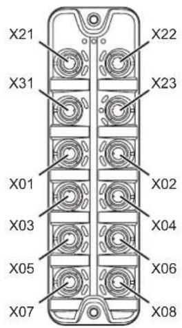
X21 Ethernet port 1 (Powerlink)
X22: Ethernet port 2 (Powerlink)
X23: IoT port
X31: Power IN - power supply
X01: IO-Link port Class A:
X02: IO-Link port Class A:
X03: IO-Link port Class A:
X04: IO-Link port Class A:
X05: IO-Link port Class A:
X06: IO-Link port Class A:
X07: IO-Link port Class A:
X08: IO-Link port Class A:
6.2 General wiring information
The unit must be connected by a qualified electrician.
▶ Observe the national and international regulations for the installation of electrical equipment.
The unit is only suitable for operation using SELV/PELV voltages.
▶ Take information about IO-Link configuration into consideration!
This device contains components that may be damaged or destroyed by electrostatic discharge (ESD).
▶ Please observe the required precautions against electrostatic discharge!
By means of basic insulation according to EN61010-1, the circuits are isolated from each other and from device surfaces that could be touched (secondary circuit with V DC maximum, supplied from mains circuit up to 300 V overvoltage category II).
By means of basic insulation according to EN61010-1, the communication interfaces are separated from each other and from device surfaces that could be touched (secondary circuit with V DC maximum, supplied from mains circuit up to 300 V overvoltage category II). They are designed for network environment 0 according to IEC TR62102).
6.2.1 General notes on wiring
The M12 connection parts in the device comply with the ingress resistance requirements of the standard EN 61076-2-101. For compliance with the protection rating, only cables certified according to this standard may be used. The system architect undertakes to ensure the ingress resistance of cables they have cut to length.
Carry out the fitting according to the indications of the cable manufacturer. Maximum permissible tightening torque: 0.8 Nm.
During installation, place the M12 connector vertically so that the coupling nut will not damage the thread.
▶ Provide cables with a strain relief depending on the mounting conditions to avoid excessive strain on the installation points and the M12 connections.
▶ Ensure correct fit and proper assembly of the M12 connection parts. If these instructions are not complied with, the specified protection rating cannot be guaranteed.
▶ Cover unused sockets with M12 protective caps (art. no.:E12542).
For UL applications:
To connect the master and the IO-Link devices, only use UL-certified cables belonging to category CYJV or PVVA with a minimum temperature of 80 °C (75 °C in case of a maximum ambient temperature of 40 °C).
6.3 Feldbus ports

natural_image
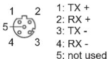
Technical line drawing of a mechanical component with multiple circular features and mounting holes (no text or symbols)The device is connected to the Powerlinknetwork via the Powerlinkports (e.g. Powerlinkcontrol, additional Powerlinkdevice).
▶ Connect the device to the Powerlink network via the X21, X22 ports.
For connection, use M12 connectors (with at least protection rating: IP 65 / IP 66 / IP 67 / IP 69K).
Wiring:

6.4 IoT port
natural_image
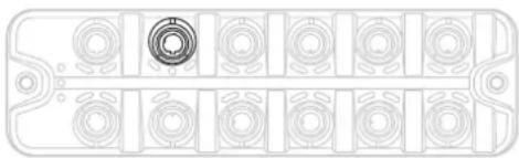
Technical line drawing of a mechanical component with multiple circular features and a central bore (no text or symbols)The IoT port connects the device to an IT network (e.g. laptop with configuration tool, monitoring software or IoT-enabled software).
▶ Connect the devic to the IT network via port X23.
For connection, use M12 connectors (with at least protection rating: IP 65 / IP 66 / IP 67 / IP 69K).
Wiring:
6.5 IO-Link ports (Class A)

natural_image
Technical diagram of a mechanical component with multiple circular features and mounting holes (no text or symbols)IO-Link devices are connected to the unit via the IO-Link ports (sensors, actuators).
The IO-Link ports meet the requirements of the IO-Link specifications 1.0 to 1.1.2.
Wiring information:
- The connected IO-Link devices must be supplied exclusively via the IO-Link master.
- The ports have an additional digital input (type 2, according to IEC 61131-2).
Wiring:

1: Sensor supply (US) L+
2: Digital input
3: Sensor supply (US) L-
4: C/Q IO-Link
5: not used
6.5.1 Connecting IO-Link devices (Class A)
Wiring information:
- The connected IO-Link devices must be supplied exclusively via the IO-Link master.
Connect the IO-Link devices with the ports X01...X08. Maximum cable length per port: 20 m
For connection, use M12 connectors (with at least protection rating: IP 65 / IP 66 / IP 67 / IP 69K).
6.5.2 Connecting IO-Link devices (Class B)
Wiring information:
- The connection of IO-Link devices (Class B) requires the supply with an additional auxiliary voltage UA. Feeding is done with the help of a Y-connection cable ( accessories).

CAUTION
Non-compliance with the electrical separation of the circuits
▷ Risk of fire
▶ Ensure that the external supply UA is electrically separated from the power circuit of the unit by basic insulation (according to IEC 61010-1, secondary current circuit with max. 30 V DC, derived from mains circuit up to 300 V of overvoltage category II).
▶ Ensure that the IO-Link devices and the connection technology support the electrical separation.
- When connecting an IO-Link device (Class B), the additional digital input at pin 2 of the port is not available.
▶ Connect IO-Link devices to ports X01...X08 via Y-connection cable.
▶ Connect Y cabes to the supplyvoltage 24 V DC (20...30 V SELV/PELV)
For connection, use M12 connectors (with at least protection rating: IP 65 / IP 66 / IP 67 / IP 69K).
6.6 Ground connection
The FE potential is connected to the following points of the device:

natural_image
Front view of a rectangular electronic component with multiple circular slots and a central hole (no text or symbols)• upper mounting lug of the housing

To ensure the protection of the device against electrical interference and to ensure the safe function of the device, the housing has to be connected to the GND of the installation using the shortest possible route.
▶ Ground the unit via the mounting screw of the upper mounting lugs.
6.7 Voltage supply
The unit is connected to the power supply via the Power-IN port.

natural_image
Technical line drawing of a mechanical component with multiple circular features and a central circular feature (no text or symbols)▶ Disconnect power!
Connect the device via port X31 to 24 V DC (20...30 V SELV/PELV; according to IEC 61010-1, secondary circuit with max. 30 V DC, supplied from main circuit up to 300 V of overvoltage category).
▶ Use an L-coded M12 connector (minimum protection type: VARIABLE).

Recommended max. cable length: 25 m.
In case of cables that are longer than 25 m, take the voltage drop and the necessary minimum supply voltage of 20 V into consideration!
Wiring:

1: + 24 V DC (US)
2: not used
3: GND (US)
4: not used
7 Operating and display elements
7.1 LEDs

1: Status: RDY
2: Status: BE
3: Status: component placement side
4: Powerlink: LNK
5: Powerlink: ACT
6: IoT: LNK
7: IoT: IoT
8: IoT: ACT
9: IO-Link:
10: IO-Link: DI
11: Power In: US
7.1.1 Status
| LED Description Colour State Description | ||||
| RDY Gateway status green off Gateway | not active | or restarts | ||
| flashes (5 Hz) Gateway: Error | ||||
| flashes (200 ms on, 800 ms off) | Gateway: Firmware update running | |||
| on Gateway: OK | ||||
| BE Network status red off Bus Failure: Error | ||||
| on Bus Failure: no error | ||||
| component placement side | Powerlink status green off Bus state: Status "NOT_ACTIVE" or "INITIALISATION" | |||
7.1.2 Ethernet
| LED Description Colour State Description | ||||
| LNK Status of the connection green off no Ethernet connection | ||||
| on Ethernet connection established | ||||
| ACT Status of the data transmission | yellow off no data transmission | |||
| flashes Data transmission | ||||
7.1.3 Voltage supply
| LED Description Colour State Description | ||||
| US Status | of the voltage supply green off | no supply | voltage is applied or the | applied voltageis too low |
| on Supply voltage applied | plied | |||
7.1.4 IoT
| LED Description Colour State Description | ||||
| LNK Status of the connection green off no Ethernet connection | ||||
| on Ethernet connection established | ||||
| ACT Status of the data transmission | yellow off no data transmission | |||
| flashes Data transmission | ||||
| IoT Device identification green flashes Device identification active | ||||
7.1.5 IO-Link ports (Class A)
| LED Description Colour State Description | ||||
| e | Status of the IO-Link port yellow off Port mode DI / DO: pin 4 (C/Q) = OFF | |||
| on Port mode DI / DO: | Pin 4 (C/Q) = ON | |||
| green flashes (1 Hz) Port mode IO-Link: no IO-Link device found | ||||
| flashes (5 Hz) Port mode IO-Link: Status “PREOPERATE” | ||||
| on Port mode IO-Link: Status “OPERATE” | ||||
| red flashes (1.2 Hz) Port configuration error or short circuit / overload on US | ||||
| on Transmission error | ||||
| DI | Status of the digital input (pin 2) | yellow off Digital input: Pin 2 = OFF | ||
8 Set-up
▶ Install the unit correctly.
▶ Establish a correct electrical connection with the device.
Once connected to the supply voltage, the unit will start.
The LEDs show status and error conditions.
▷ The unit is ready for operation.
The device can be configured.
9 Settings
9.1 Configuration tools
9.1.1 Supported configuration tools
The device can be configured with the following configuration tools:
- LR DEVICE
- ifm moneo suite
- ifm moneo configure (SA)
▶ Install the required configuration tool.
▶ Activate the licences required for operation.
The configuration tool can be used to set the parameters of the unit.
9.1.2 Getting started
Requirements:
√ The configuration tool is correctly installed on the laptop / PC.
√ The laptop / PC is connected to the IoT port of the unit.
▶ Start the configuration tool.
▶ Scan the network for devices.
The configuration tool recognises the unit.
▶ Optional: Adapt the IP settings of the device.
The configuration tool can access IO-Link masters and the connected IO-Link devices.
9.1.3 IoT interface
The device is connected to the IT network via the IoT interface.
IoT: Configuring IP settings
For communication with the IT network, the IP parameters of the IoT interface must be configured.
▶ Select [IoT] menu.
| Parameter Description Value range Access | |||
| DHCP Enable / disable the D | HCP client • Static IP: DHCP client disabled | IP parameters are set by the user • DHCP DHCP client enabled; IP parameters are set by the network's DHCP server. | rw^1 |
| IP address IP address of the | IoT interface e.g. 192.168.100.1 (default) | rw | ^2 |
| Subnet mask Subnet mask of | the Ethernet network e.g. 255.255.255.0 | (default) rw | ^2 |
| Default gateway IP address | IP address of the network gateway | e.g. 0.0.0.0 (default) | rw^2 |
| MAC address | MAC address of the IoT interface | ro^3 | |
^1 read and write
^2 read and write; can only be changed if DHCP client is enabled
^3 read only
▶ Save the changes on the device.
IoT: Configuring security mode
The unit provides a security mode. The security mode makes it possible to protect access to IO-Link masters and connected IO-Link devices from the IT network. When security mode is activated, the following restrictions apply:
- Access only by authentication (password protection)
- Access only via encrypted connection (TLS - Transport Layer Security)

The security mode only protects access and data transmission via the IoT interface.
The user name administrator cannot be changed.
The security mode can be enabled without setting the password at the same time. The next time the unit is accessed, the configuration tool requires the password to be set.
After entering the correct password, the user has unrestricted access to the IO-Link master and the connected IO-Link devices. The password is requested again when the current configuration tool session has ended (e.g. after a restart).
To configure the security mode:
▶ Select [IoT] menu.
| Parameter Description Value range Access | |||
| Security mode HTTPS Enabling / disabling security mode • Disabled: Security mode disabled• Enabled: Security mode enabled | rw^1 | ||
| Security password Password for authenticationNote: The set password is not displayed. | wo^2 | ||
^1 read and write
^2 write only
▶ Save the changes on the device.
IoT: Configuring access rights
The access rights define which control instance may read or write the parameters, process data and event / diagnostic messages.
▶ Select [IoT] menu.
| Parameter Description Value range Access | |||
| Access Rights Access rights on the IO-Link master • Fieldbus + IoT (default):– Fieldus and ifm IoT Core have read and write access rights to parameters and process data– Fieldbus and ifm IoT Core have read access rights to events/alarms• Fieldbus + IoT (read only):– Fieldbus has read and write access rights to parameters and process data– Fieldbus has read access rights to events/alarms– ifm IoT Core only has read access rights to parameters, process data and events/alarms• IoT only:– ifm IoT Core has read and write access rights to parameters and process data– IoT has read access rights to events/alarms– Fieldbus has no access rights | rw^1 | ||
^1 read and write
▶ Save the changes on the device.
IoT: Configuring the interface to the monitoring software
For optional transmission of process data to monitoring software moneo, LR AGENT or LR SMARTOBSERVER, the interface must be configured accordingly.
▶ Select [IoT] menu.
| Parameter Description Value range Access | |||
| IP address Moneo, LR Agent or SMARTOBSERVER | IP address of moneo, LR AGENT or LR SMARTOBSERVER | 0.0.0.0...255.255.255.255 (default) | rw^1 |
| Port Moneo, LR Agent or SMARTOBSERVER | Number of the moneo port, LR AGENT or LR SMARTOBSERVER to which the process data is sent | 0...35100 (default)...65535 | rw^1 |
| Interval Moneo, LR Agent or SMARTOBSERVER | Cycle time for the transfer of the process data to moneo, LR AGENT or LR SMARTOBSERVER (value in ms) | Off: no transmission(default)500: 500 ms...2147483647: 2147483647 ms | rw^1 |
| Application tag Source identifier of the IO-Link master in the structure of the LR AGENT or LR SMARTOBSERVER (String32) | AL1373 (default) rw | 1 | |
^1 read and write
▶ Save the changes on the device.
After changing the parameters [IP address Moneo, LR Agent or SMARTOBSERVER] or [Application Tag], it may take up to 20 seconds until the device will establish a TCP connection again.
To prevent the delay:
▶ Restart the device.
9.1.4 Fieldbus interface
Fieldbus: Configuring the interface
▶ Select [Fieldbus] menu.
| Parameter Description Value range Access | |||
| IP address IP address of the fieldbus interface e.g. 192168100139 ro | ^1 | ||
| Subnet mask Subnet mask of the fieldbus network e.g. 255.255.255.0 ro | ^1 | ||
| Default gateway IP address IP address of the network gateway e.g. 192168100254 ro | ^1 | ||
| Host name | Powerlink Hostname | e.g. AL1x7x | rw^2 |
| MAC address | MAC address of the fieldbus interface of the IO-Link master | e.g. 00:02:01:0f:C8:8F | ro^1 |
| Fieldbus firmware | Fieldbus firmware of the IO-Link master | e.g. | ro^1 |
| nodeID | Powerlink node identifier of the unit | • 1: 1 (default)...• 239: 239 | rw^2 |
| installationLocation | Installation location of the unit | e.g. Plant3 | rw^2 |
^1 read only
^2 read and write
▶ Save the changes on the device.
9.1.5 Ports
Ports: Setting the data transmission to the monitoring software
▶ Select the [Port n] menu (n: 1...8).
| Parameter Description Value range Access | |||
| Port n: Transmission to Moneo, LR Agent or SMAR-TOBSERVER | Enable / disable transmission of the process data of the connected sensors to moneo, LR AGENT or LR SMAR-TOBSERVER | • Disabled: Process data not transferred • Enabled: Process data transmitted | rw1 |
^1 read and write
▶ Save the changes on the device.
Ports: Setting the operating mode Pin 4 (US)
▶ Select the [Port n] menu (n: 1...8).
| Parameter Description Value range Access | ||
| Port n: Mode Pin4 US Operating mode of Pin 4 (C/Q) of the port | • Disabled: Port disabled• DI: Digital input• DO: Digital output• IO-Link: IO-Link process data | rw ^1 |
^1 read and write
▶ Save the changes on the device.
Ports: Setting validation and data storage
▶ Select the [Port n] menu (n: 1...8).
| Parameter Description Value range Access | |||
| Port n: Validation / Data Storage | Validation of the connected IO-Link devices and automatic recovery of the parameter sets of the IO-Link device | No check and clear:No compatibility checkNo backup / restore of parameter valuesType compatible V1.0 device:Compatibility check on IO-Link standard V1.0No backup / restore of parameter valuesType compatible V1.1 deviceCompatibility check on IO-Link standard V1.1No backup / restore of parameter valuesType compatible V1.1 device with Backup + Restore:Compatibility check on IO-Link standard V1.1Automatic storage of the parameter values; Changes are savedAutomatic recovery of the parameter values when connecting an identical IO-Link device with factory settingsType compatible V1.1 device with RestoreCompatibility check on IO-Link standard V1.1No storage of the parameter valuesAutomatic recovery of the parameter values when connecting an identical IO-Link device with factory settings | rw ^1 |
| Parameter Description Value range Access | ||
| Port n: Vendor ID Vendor ID of the IO-Link device to be validated against | e.g. 310: ifm electronic gmbh rw | ^1 |
| Port n: Device ID Device ID of the IO-Link device to be validated against | e.g. 1129: TCC501 (ifm temperature sensor) | rw ^1 |
1 read and write; Parameter only available if operating mode pin 4 (US) = IO-Link and IO-Link device is connected to port
▶ Save the changes on the device.
Ports: Setting the cycle time
▶ Select the [Port n] menu (n: 1...8).
| Parameter Description Value range Access | |||
| Port n: Cycle time actual Current cycle time between the IO-Link master and the IO-Link device (value in μs) | • 0: best possible cycle time...• 132800: 132800 μs | ro ^1 | |
| Port n: Cycle time preset Cycle time between the IO-Link master and the IO-Link device (value in μs) | • 0: The IO-Link master automatically sets the best possible cycle time• 1: 1 μs...• 132800: 132800 μs | rw ^2 | |
| Port n: Bit rate Transmission rate between the IO-Link master and the IO-Link device | • COM1: 4.8 kbaud• COM2: 38-4 kbaud• COM3: 230.4kbaud | ro ^1 |
^1 read only; Parameter only available if operating mode pin 4 (US) = IO-Link and IO-Link device is connected to port
^2 read and write; Parameter only available if operating mode pin 4 (US) = IO-Link and IO-Link device is connected to port
▶ Save the changes on the device.
9.1.6 Info
Info: Displaying the device information
▶ Select [Info] menu.
| Parameter Description Value | range Access | ||
| Product code Article number | AL1373 ro | ^1 | |
| Device family Device family | IO-Link master | ro | ^1 |
| Vendor | Manufacturer | ifm electronic gmbh | ro ^1 |
| SW revision | Firmware version | e.g. AL1x7x_cn_pl_v3.3.40 | ro ^1 |
| HW revision | Hardware revision | e.g. AB | ro ^1 |
| Bootloader revision | Bootloader version | e.g. AL1xxx_bl_f7_v1.2.0 | ro ^1 |
| Serial number | Serial number | e.g. 0002043100003 | ro ^1 |
| Fieldbus type | Fieldbus | Powerlink | ro ^1 |
^1 read only
9.1.7 Firmware
Firmware: Showing the firmware version
▶ Select [Firmware] menu.
| Parameter Description Value range Access | |||
| Version | Firmware version | e.g. AL1x7x_cn_pl_v3.3.40 | ro ^1 |
^1 read only
Firmware: Resetting the device
Only available with LR DEVICE
▶ Select [Firmware] menu.
▶ Click on [Factory Reset].
The device will be reset to the factory settings.
▷ All parameters are set to their default values.
Firmware: Rebooting the device
Only available with LR DEVICE
▶ Select [Firmware] menu.
▶ Click on [Reboot].
The device will be restarted.
▷ All set parameter values will be retained.
9.1.8 IO-Link devices
The unit supports access to connected IO-Link devices (sensors, actuators) with the configuration tools.
Requirements:
√ The IO-Link master is correctly mounted and electrically connected.
√ The IO-Link device is correctly connected to the IO-Link port of the device.
√ The configuration tool is connected to network.
√ Operating mode Pin 4 (US) of the IO-Link port is "IO-Link" (→ Ports: Setting the operating mode Pin 4 (US) □ 20).
√ IoT has read and write rights to the device (→ IoT: Configuring access rights ☐ 18).
▶ Update the IODD library of the configuration tool.
▶ Scan the network for devices.
The configuration tool detects the IO-Link master.
▶ Click on the IO-Link master found.
The configuration tool displays a detailed view of the IO-Link master.
The configuration tool recognises the connected IO-Link device.
▶ Click on the IO-Link device.
▷ A detailed view of the IO-Link device appears.
The detailed view shows the current parameter values of the IO-Link device.
▶ Configure the IO-Link device.
▶ Store the changed configuration of the IO-Link device.
9.2 ifm IoT Core
9.2.1 ifm IoT Core: General information
The device has the ifm IoT Core. The ifm IoT Core represents the functionality of a device. Each device is represented by a number of objects, services and events. The elements of the ifm IoT Core are arranged in a JSON object in a hierarchical tree structure. The ifm IoT Core makes these elements available to the outside world via standard interfaces. This allows the user and other devices to access data (parameters, process data, events) and functions (services) of the ifm IoT Core.
Accessing the ifm IoT Core
An element of the ifm IoT Core is accessed via its address (e.g. root/port1/pin2). The address is composed of the path leading to the element (root/port1) and the identifier of the element (pin2).
The user can access the ifm IoT Core via HTTP requests. The following methods are supported:
GET method
Access: reading
Syntax of the request:
http://ip/datapoint/service
| Parameter Description | |
| ip IP address of the IoT | interface |
| data_point Data point which is to be accessed | |
| service Service | |
Syntax of the response:
{
    "cid": id,
    "data": {"value": resp_data},
    "code": diag_code
}
| Parameter Description | |
| id Correlation ID for the | assignment of request and reply |
| resp_data Value of the data point; depending on the data type of the data point | |
| diag_code | Diagnostic code Diagnostic codes (→ 25) |
Example: GET request
- Request:
http://192.168.0.250/devicetag/applicationtag/getdata
- Response:
{
    "cid": -1,
    "data": {"value":"AL1373"},
    "code": 200
}
POST method
Access: reading, writing
Syntax of the request:
{
    "code": "code_id",
    "cid": id,
    "adr": "data_point/service",
    "data": {req_data},
    "auth": {"user": "usr_id", "passwd": "password"}
}
| Field Parameter Description | ||
| code code_id Service class | request: Requesttransaction: Transactionevent: event | |
| cid id Correlation ID for the assignment in pairs of request and return identifier freely assignable by the user | ||
| adr data_point Data point of the element tree to be accessed | ||
| service | service to be performed ( Services || 70) | |
| data ^1 | req_data Data sent to the ifm IoT Core (e.g. new values); Syntax depending on the service | |
| auth ^2 | usr_id User name (BASE64 coded); Default: administrator | |
| password Passwort (BASE64-coded) | ||
1 optional; only required for services that send data to the ifm IoT Core (e.g. setdata)
^2 optional; only required if security mode is activated
Syntax of the response:
{
    "cid": id,
    "data": {resp_data},
    "code": diag_code
}
| Field Parameter Description | ||
| cid id | Correlation ID for the assignment of request and return (→ Request) | |
| data1 | resp_data Values returned by the ifm IoT Core; Syntax depending on the service | |
| code diag_code | Diagnostic code (→ Diagnostic codes 125) | |
1 optional; only available for services that receive data from the ifm IoT Core (e.g. getdata)
Device-specific error codes are output in the event of faulty acyclic access to connected IO-Link devices.
Syntax of the response in the event of incorrect access:
{
    "cid": id,
    "error": err_code,
    "code": diag_code
}
| Field Parameter Description | ||
| cid id | Correlation ID for the assignment of request and return (→ Request) | |
| error err_code | device-specific error code (→ IO Device Description (IODD) of the IO-Link device) | |
| code diag. code | Diagnostic code (→ Diagnostic codes □ 25) | |
Example: POST request
- Request:
{
    "code":"request",
    "cid":-1,
    "adr":"devicetag/applicationtag/getdata"
}
- Response:
{
    "cid": -1,
    "data": {"value":"VARIABLE_LINK"},
    "code": 200
}
Diagnostic codes
| Code Text Description | |
| 200 OK Request successfully processed | |
| 230 OK but needs reboot Request successfully processed The IO-Link master must be rebooted | |
| 231 OK but block request not finished Request successfully pro | processed blockwise request, but not fin-ished |
| 233 IP settings (of IoT-Port) have been updated. Ap-plication needs to reload device. Wait at least 1 second before reloading the device. | The IP settings have been successfully changed, IO-Link mas-ter will be reloaded; wait for at least 1 second |
| 400 Bad request Invalid request | |
| 401 Unauthorized Non authorised request | |
| 403 Forbidden Forbidden request | |
| 500 Internal Server Error Internal fault; detailed information in | the "error" field |
| 503 Service Unavailable Service not available (e.g. IO-Link port in wrong operating mode; no IO-Link device on IO-Link port) | |
| 507 Insufficient Storage The | internal memory for notifications is full (max. 16 kB) |
| 530 The requested data is invalid Invalid process data | |
| 531 IO-Link Error Error | in IO-Link master / IO-Link device; detailed information in the "error" field |
| 532 PLC connected Error Error | when writing data because IO-Link master is still connect-ed to fieldbus PLC |
9.2.2 Getting started
To register the device description of the VARIABLE_AL1330:
▶ Send the following POST request to the ifm IoT Core: {"code":"request", "cid):-1, "adr":"gettree"}
▷ ifm IoT Core returns the device description as a structured JSON object.
▶ Identify all substructures and the data points contained therein in the tree structure of the JSON object.
▶ Identify the applicable services for the access to substructures and the data points contained therein.
9.2.3 General functions
The device has the type "device" ( Types ☐ 70). The following services can be applied to the root element of the device tree:
| Service Description | |
| ../gettree Provide the complete tree for subtree of the device description (JSON) | |
| ../getidentity Read identification information of the device | |
| ../getdatamulti Reading several elements sequentially | |
| ../getelementinfo Reading detailed information of an element | |
| ../getsubscriberlist Print a list of all active notification subscriptions | |
| ../querytree Search device description for specific elements | |
The following services can be applied to elements of the type data depending on its access rights:
| Service Description | |
| ../getdata Reading the value of the element | |
| ../setdata Write the value of the element |
Example: Reading properties of an element
Task: Determine the data type and value range of the accessrights parameter.
Solution: Read the properties of the element iotsetup/accessrights of the getelementinfo service. The fields type (data type) and valuation (range of values) contain the required information.
- Request:
{
    "code":"request",
    "cid":4711,
    "adr":"getelementinfo",
    "data":{"adr":"iotsetup/accessrights"}
}
- Response:
{
    "cid":4711,
    "data":{
    "identifier":"accessrights",
    "type":"data",
    "uid":null,
    "profiles":["parameter"],
    "format":{
    "type":"enum",
    "namespace":"json",
    "encoding":"integer",
    "valuation":{
    "valuelist":{
    "0":"Fieldbus + IoT",
    "1":"Fieldbus + IoT (read-only)",
    "3":"IoT only"}
    }
    }
},
"code":200
}
The accessrights parameter has the data type ENUM with the valid values "Fieldbus + IoT", "Fieldbus + IoT (read only)" and "IoT only".
Example: Outputting the subtree
Task: Output all direct sub-elements of the node firmware.
Solution: Use the service gettree to output the required subtree (root node: firmware, sub-levels to be shown: 1)
- Request:
{
    "code": "request",
    "cid": 4711,
    "adr": "gettree",
    "data": {"adr": "firmware", "level": 1}
}
- Response:
{
    "cid":4711,
    "data":{
    "identifier":"firmware",
    "type":"structure",
    "profiles":["software","software/uploadablesoftware"],
    "subs":[
    {"identifier":"version","type":"data","profiles":["parameter"],
    "format":{"type":"string","namespace":"json","encoding":"UTF-8"}},
    {"identifier":"type","type":"data",
    "format":{"type":"string","namespace":"json","encoding":"UTF-8"}},
    {"identifier":"install","type":"service"},
    {"identifier":"factoryreset","type":"service"},
    {"identifier":"signal","type":"service"},
    {"identifier":"container","type":"data",
    "format":{"type":"binary","namespace":"json","encoding":"base64"}}},
    {"identifier":"reboot","type":"service"}
    ]
    },
    "code":200
}
Example: Changing a parameter value
Task: The Application Tag parameter of the unit is to be written with the value "Do not use". The new value is only supposed to be valid until the next reboot of the unit.
Solution: Write the new value of the applicationspecifictag element with the setdata service. To keep the new value only until the next restart of the unit, pass on the duration option with the uptime value.
- Request:
{
    "code": "request",
    "cid": 4711,
    "adr": "/devicetag/applicationtag/setdata",
    "data": {"duration": "uptime", "newvalue": "Do not use"}
}
- Response:
{
    "cid":4711,
    "code":200,
}
Example: Reading several elements sequentially
Task: The following current values are to be read by the IO-Link master. Temperature, serial number
Solution: Read the current parameter values using the getdatamult (data point temperature service: / processdatamaster/temperature; Data point serial number: /deviceinfo/serialnumber)
- Request:
{
    "code": "request",
    "cid": 4711,
    "adr": "/getdatamulti",
    "data": {"datatosend": [
    "/processdatamaster/temperature",
    "/deviceinfo/serialnumber"]
    }
}
- Response:
{
    "cid":4711,
    "data":{
    "processdatamaster/temperature":{"code":200,"data":44},
    "deviceinfo/serialnumber":{"code":200,"data":"000174210147"}},
    "code":200
}
Example: Browsing device description
Task: List all elements with the designation "status" and the profile "runcontrol".
Solution: Use the service querytree to browse the device description with the parameters "status" (name) and "runcorntrol" (profile)
- Request:
{
    "cid":4711,
    "code":"request",
    "adr":"querytree",
    "data":{"profile":"runcontrol","name":"status"}
}
- Response:
{
    "cid":4711,
    "data":{"adrList":[
    "device/connections/mqttConnection/status",
    "device/connections/mqttConnection/mqttCmdChannel/status"]},
    "code":200
}
DNS support
The ifm IoT Core supports the Domain Name System (DNS) service for the name resolution of IP addresses. The user can use the corresponding host name instead of the concrete IP address in the request. DNS can be used both for addressing the IoT core and for addressing network participants.
Example: Using DNS support
Example 1: gettree
Synonymous requests:
- http://192.168.23.70:8080/gettree
- http://example.org:8080/gettree
Example 2: subscribe
Synonymous requests:
- with IP address:
{
    "cid":11,
    "code":10,
    "adr":"setasync/datachanged/subscribe",
    "data":{
    "datatosend":["setasync"],
    "callback":"192.168.23.70:8080/dump"
}
- with host name:
{
    "cid":11,
    "code":10,
    "adr":"setasync/datachanged/subscribe",
    "data":{
    "datatosend":["setasync"],
    "callback":"http://example.com:8080/dump"
}
9.2.4 IoT
IoT: Configuring access rights
Substructure: iotesetup
Available data points:
| Name Description Access | ||
| .../accessrights Access rights on the | IO-Link master rw | 1 |
^1 read and write
IoT: Configuring IP settings
Substructure: iotsetup/network
Available data points:
| Name Description Access | ||
| ../dhcp Activate / deactivate DHCP mode rw | 1 | |
| ../ipaddress IP address of the IoT interface rw | 1 | |
| ../subnetmask Subnet mask of the network segment rw | 1 | |
| ../ipdefaultgateway IP address of the network gateway rw | 1 | |
^1 read and write
Applicable services:
| Name Description | |
| ../setblock write all data points of the | substructure blockwise |

Write the data points of the substructure only with the setblock service!
IoT: Configuring security mode
The unit provides a security mode. The security mode makes it possible to protect access to IO-Link masters and connected IO-Link devices from the IT network. When security mode is activated, the following restrictions apply:
- Access only by authentication (password protection)
- Access only via encrypted connection (TLS - Transport Layer Security)

The security mode only protects access and data transmission via the IoT interface.
The user name administrator cannot be changed.
The set password cannot be read with getdata.
The current status of the security mode can be read with the getidentity service ( Service: getidentity ☐ 72).
For the authentication, the user must additionally provide the POST requests with a valid user name and password in the field "auth". The user name and the password are shown as Base64-coded character strings.
The following requests can be done if the security mode is enabled, also without authentication:
• /getidentity
• /deviceinfo/vendor/getdata
• /deviceinfo/productcode/getdata
Substructure: iotsetup
Available data points:
| Name Description Access | ||
| ../security/securitymode Enabling / disabling security mode rw | 1 | |
| ../security/password Password for authentication (Base64 coded) wo | 2 | |
^1 read and write
^2 write only

Valid character set for the Base64 coding / decoding of the password: UTF-8
Online tool for coding / decoding: www.base64encode.org
Example: Activating security mode
Task: The security mode of the IoT interface is to be activated. The valid password is to be set to "password" (BASE64-coded: cGFzc3dvcmQ=).
Solution: Activate the security mode via the data point iotsetup/security/securitymode. Write the required password to the data point iotsetup/security/password.
Activating security mode
- Request:
{
    "code": "request",
    "cid": -1,
    "adr": "/iotsetup/security/securitymode/setdata",
    "data": {"newvalue":"1"}
}
- Response:
{
    "cid": -1,
    "code": 200
}
Setting the password
- Request:
{
    "code": "request",
    "cid": -1,
    "adr": "/iotsetup/security/password/setdata",
    "data": {"newvalue": "cGFzc3dvcmQ="}
}
- Response:
{
    "cid": -1,
    "code": 200
}
Example: Request with authentication
Task: The temperature of the IO-Link master is to be read. The security function is enabled (current password: password).
Solution: Read the data point processdatamaster/temperature. The request must be sent using https. The user name and the password are transferred as a Base64-coded character string ("administrator" = "YWRtaW5pc3RyYXRvcg==", "password" = "cGFzc3dvcmQ=")
- Request:
{
    "code": "request",
    "cid": -1,
    "adr": "processdatamaster/temperature/getdata",
    "auth": {"user": "YWRtaW5pc3RyYXRvcg==", "passwd": "cGFzc3dvcmQ="}}
}
- Response:
{
    "cid": -1,
    "data": {"value": 37},
    "code": 200
}
Example: Resetting the password
Task: The existing password is to be reset.
Solution: To reset a password, disable the security mode. To disable it, enter the user name and the password (the fields "user" and "passwd").
- Request:
{
    "code": "request",
    "cid": -1,
    "adr": "iotsetup/security/securitymode/setdata",
    "data": {"newvalue": 0},
    "auth": {"user": "YWRtaW5pc3RyYXRvcg==", "passwd": "SW9UNG1mbQ=="}
}
- Response:
{
    "cid": -1,
    "code": 200
}
IoT: interface to moneo, configuring LR AGENT and LR SMARTOBSERVER
Substructure: iotsetup
Available data points:
| Name Description Access | ||
| ../smobip IP address of moneo, LR | AGENT or LR SMARTOBSERVER rw | 1 |
| ../smobport Number of the moneo port, LR | AGENT or LR SMARTOBSERVER to which the process data is sent | rw 1 |
| ../smobinterval Cycle time for the transfer of the process data to moneo, LR | AGENT or LR SMARTOBSERVER (value in ms) | rw 1 |
^1 read and write
Substructure: devicetag
Available data points:
| Name Description Access | ||
| ../applicationtag Designation of the | O-Link master in moneo, LR AGENT or LR SMARTOB-SERVER | rw ^1 |
^1 read and write

32 bytes are available on the IO-Link master for storing the applicationtag parameter. If the memory range is exceeded, the IO-Link master will abort the write process and return the diagnostic code 400.
When writing the applicationtag parameter, note the different memory requirements of the individual UTF-8 characters (characters 0-127: 1 byte per character; character >127: more than 1 byte per character).
9.2.5 Fieldbus
Fieldbus: Configuring the POWERLINK interface
Substructure: fieldbussetup
Available data points:
| Name Description Access | ||
| ../nodeid Node ID of the IO-Link master | aster in fieldbus project• 1: Node ID 1...• 239: Node ID 239 | rw ^1 |
| ../installationlocation Designation for | place of installation (freely selectable, max. 20 characters) rw | ^1 |
| ../connectionstatus Status of the connection to thenetwork• 0: not connected• 1: connected | network | ro ^2 |
| ../hostname Name of themaster in the fieldbus project rw | master | 1 |
| ../fieldbusfirmware Firmware version of the IO-Link master ro | of the IO-Link master ro | 2 |
| ../network/ipaddress IP address of the fieldbus interface ro | IP address of the fieldbus interface ro | 2 |
| ../network/subnetmask Subnet mask of the network segment ro | Subnet mask of the network segment ro | 2 |
| ../network/ipdefaultaddress IP address of the network gateway ro | IP address of the network gateway ro | 2 |
| ../network/macaddress MAC address of the fieldbus interface ro | MAC address of the fieldbus interface ro | 2 |
^1 read and write
^2 read only
9.2.6 Ports
Ports: Setting the operating mode Pin 4 (US)
Substructure: iolinkmaster/port[n] (n: 1...8)
Available data points:
| Name | Description Access | |
| ../mode | Operating mode Pin 4 (US) of the port | rw^1 |
| ../mastercycletime_preset | Cycle time of the data transmission on the port (value in μs) | rw^1 |
| ../mastercycletime_actual | current cycle time of the data transmission on the port (value in μs) | ro^2 |
| ../comspeed | Data transfer rate of the port | ro^2 |
1 read and write; can only be changed if no connection to the fieldbus controller is active
^2 read only
Ports: Configuring the device validation and data storage
Substructure: iolinkmaster/port[n] (n: 1...8)
| Name Description Access | ||
| ../validation_datastorage_mode | Behaviour of the port when connecting a new IO_Link device | rw^1 |
| ../validation_vendorid | IO-Link ID of the manufacturer that is to be validated | rw^1 |
| ../validation_deviceid | IO-Link ID of the equipment to be validated | rw^1 |
| ../datastorage | Structure for port data storage | rw^1 |
| ../datastorage/maxsize Maximum size | of the data storage content (in bytes) ro | 2 |
| ../datastorage/chunksize | Size of a data segment (in bytes) | ro^2 |
| ../datastorage/size | Size of the data storage content (in bytes) | ro^2 |
^1 read and write; can only be changed if no connection to the fieldbus controller is active
^2 read only
Applicable services:
| Name | Description |
| ../validation_useconnecteddevice | Validate the IO-Link device |
| ../datastorage/getblobdata | Reading the content of the data storage area |
| ../datastorage/stream_set | Transfer an individual data segment |
| ../datastorage/start_stream_set | Start sequential transmission of several data segments |
Example: Cloning the data memory of an IO-Link port
Task: The data memory of port 2 of IO-Link master 1 is to be cloned to IO-Link master 2.
Solution: The cloning consists of 2 steps. In the first step, the data memory of the port is read by IO-Link master 1. In the second step, the read data is stored in the data memory of the port of IO-Link master 2.
Read data memory
▶ Read segment size of the data storage (h = number of bytes)
{
    "code": "request",
    "cid": -1,
    "adr": "/iolinkmaster/port[2]/datastorage/chunksize/getdata"
}
Example: h = 256
▶ Read total size of the data storage (g = number of bytes)
{
    "code": "request",
    "cid": -1,
    "adr": "/iolinkmaster/port[2]/datastorage/size/getdata"
}
Example: g = 550
▶ Calculate the number of reading steps n: n = first integer value for which applies: g < n*h
Example: n=3, da 550 < 3*256
Read the data storage segment by segment ("pos" indicates the byte offset at which the read process starts with the length "length").
{
    "code": "request",
    "cid": -1,
    "adr": "/iolinkmaster/port[2]/datastorage/getblobdata",
    "data": {"pos": 0, "length": h}
}
{
    "code": "request",
    "cid": -1,
    "adr": "/iolinkmaster/port[2]/datastorage/getblobdata",
    "data": {"pos": h, "length": h}
}
{
    "code": "request",
    "cid": -1,
    "adr": "/iolinkmaster/port[2]/datastorage/getblobdata",
    "data": {"pos": 2 * h, "length": h}
}
...
{
    "code": "request",
    "cid": -1,
    "adr": "/iolinkmaster/port[2]/datastorage/getblobdata",
    "data": {"pos": n * h, "length": h}
}
Example:
1st reading order: pos = 0, length = 256
2nd reading order: pos = 256, length = 256
3rd Read command: pos = 512, length = 256
Each segment is returned as a BASE64-encoded string.
▶ Connect segments (concatenate).
Restore data memory
▶ Determine the size of the backed-up data storage content (n = number of bytes).
Example: n = 550
▶ Read segment size (s = number of bytes)
{
    "code": "request",
    "cid": -1,
    "adr": "/iolinkmaster/port[1]/datastorage/chunksize/getdata"
}
Example: s = 256
▶ Start writing the data storage string segment by segment ("size" = size of the read data storage)
{
    "code": "request",
    "cid": -1,
    "adr": "/iolinkmaster/port[1]/datastorage/start_stream_set",
    "data": {"size": n}
}
Example: size = 550
▶ Transmit data storage string segment by segment ("value" = string value with length s)
{
    "code": "request",
    "cid": -1,
    "adr": "/iolinkmaster/port[1]/datastorage/stream_set",
    "data": {"value": "aWZtfgIAAABBTDF4NXhfY25faXRfdDIuMi43Nw..."}
}
Ports: Configuring the data transfer to LR AGENT / LR SMARTOBSERVER
Substructure: iolinkmaster/port[n] (n: 1...8)
| Name Description Access | ||
| ../senddatatosmob Send process data to LR AGENT or LR SMARTOBSERVER rw | 1 | |
^1 read and write
Ports: Reading / writing process data
Substructure: iolinkmaster/port[n] (n: 1...8)
Available data points:
| Name Description Access | ||
| ../pin2in Digital input (pin 2) ro | 1 | |
| ../iolinkdevice/pdin Input data (pin 4) ro | 1 | |
| ../iolinkdevice/pdout Output data (pin 4) rw | 2 |
^1 read only
^2 read and write; can only be changed if no connection to the fieldbus controller is active
Example: Reading an IO-Link process value (operating mode "IO-Link")
Task: Read the current measured value of the ifm temperature sensor TN2531 at port 2.
Solution: Read the value of the pdin data point.
- Request:
{
    "code":"request",
    "cid":4711,
    "adr":"/iolinkmaster/port[2]/iolinkdevice/pdin/getdata"
}
- Response:
{
    "cid":4711,
    "data":{"value":"03C9"},
    "code":200
}
The return value is displayed in hexadecimal format. The return value is given in hexadecimal format. Besides the temperature value the return value comprises additional information ( IO Device Description (IODD) of the sensor). The temperature value is shown in bits 2 to 15.
0x03C9 = 0b1111001001
Temperature value: 0b11110010 = 242
This means that The current temperature value is 24.2 °C.
Example: Writing an IO-Link process value
Task: The buzzer of the DV2500 at port 2 is to be switched on. The DV2500 operates in On/Off mode.
Solution: Write the value of the pdout data point. The IODD of the DV2500 shows the structure of the process value (e.g. LED activity). The buzzer is switched via bit 40 of the process value (OFF = 0, ON = 1).
Process sequence:
-
Read the current process value Example: Reading an IO-Link process value (operating mode "IO-Link") ( ☐ 37).
-
Set bit 40 of the read value to 1.
-
Write new process value.
Example:
Read process value:
0x0000 0000 004D = 0b0000 0000 0000 0000 0000 0000 0000 0000 0000 0100 1101
New process value:
0b0000 0001 0000 0000 0000 0000 0000 0000 0000 0000 0100 1101 = 0x0100 0000 004D
- Request:
{
    "code":"request",
    "cid":10,
    "adr":"iolinkmaster/port[2]/iolinkdevice/pdout/setdata",
    "data":{"newvalue":"01000000004D"}
}
- Response:
{
    "cid":10,
    "code":200
}
Example: Reading the digital input value (operating mode "DI")
Task: The digital input value of the IO-Link device at port 2 (pin 4) is to be read. The operating mode of the IO-Link port is "Digital Input (DI)".
Solution: Write the process value of the pdin data point. The process value is returned as a hexadecimal value with a length of 1 byte (OFF = "00", ON = "01").
- Request:
{
    "code":"request",
    "cid":10,
    "adr":"iolinkmaster/port[2]/iolinkdevice/pdin/getdata"
}
- Response:
{
    "cid":10,
    "data":{"value":"00"},
    "code":200
}
Example: Writing the digital output value (operating mode "DO")
Task: The digital input value of the IO-Link device at port 2 (pin 4) is to be read. The operating mode of the IO-Link port is "Digital Input (DI)".
Solution: Write the process value of the pdin data point. The process value is returned as a hexadecimal value with a length of 1 byte (OFF = "00", ON = "01").
- Request:
{
    "code": "request",
    "cid": 10,
    "adr": "iolinkmaster/port[2]/iolinkdevice/pdin/getdata"
}
- Response:
{
    "cid":10,
    "data":{"value":"00"},
    "code":200
}
Ports: Reading port events
A port event contains information about events on the IO-Link port (e.g. IO-Link device connected or disconnected, change of the operating mode of the port).
A port event is displayed as a value in hexadecimal format. The value is structured as follows:
| Byte 2 Byte 1 | Byte 0 | |
| Connection reserved | Device |
Legend:
- Connection Connection status 1 byte • 0x00: No IO-Link device connected
- 0x01: IO-Link device connected and in OPERATE state
- Device IO-Link device status 1 byte • 0x01: Port activated, but no device connected
- 0x02: Port activated and in "IO-Link" operating mode
- 0x03: Port activated and in "DI" or "DO" operating mode
Substructure: iolinkmaster/port[n] (n: 1...8)
Available data points:
| Name Description Access | ||
| ../portevent Port event ro | 1 |
^1 read only
9.2.7 IO-Link devices
IO-Link devices: Accessing parameters
The ifm IoT Core supports access to the parameters of connected IO-Link devices via the IT network using ISDU (Index Service Data Unit). Each parameter can be addressed via its ISDU index and ISDU subindex ( IODD of the IO-Link device). If access to the IO-Link device is faulty, the ISDU error code will also be output in the response ( IODD of the IO-Link device).
Substructure: iolinkmaster/port[n]/iolinkdevice (n: 1...8)
Applicable services:
| Name Description | |
| ../iolreadacyclic Read a parameter of an IO-Link device (acyclic) | |
| ../iolwriteacyclic Write a parameter of an IO-Link device (acyclic) | |
When using the validation level "Type compatible V1.1 Device with Backup + Restore":
After changing a parameter via ISDU write access, the user must end the parameter setting process with the "ParamDownloadStore" system command and activate the data storage mechanism on the IO-Link device.
▶ Set the SystemCommand object (ISDU index: 0x0002) to the value 0x05 (command "ParamDownloadStore") via acyclic ISDU write access.
The parameter setting process is finished.
The data storage mechanism on IO-Link device will be activated.
The IO-Link device synchronises changed parameter values with data storage of the IO-Link master.
Example: Reading a parameter value of an IO-Link device
Task: Reading the serial number of the ifm temperature sensor TN2531 at port 2.
Solution: Read the serial number with the iolreadacyclic service from the IO-Link device (index: 21, sub-index: 0)
- Request:
{
    "code": "request",
    "cid": 4711,
    "adr": "/iolinkmaster/port[2]/iolinkdevice/iolreadacyclic",
    "data": {"index": 21, "subindex": 0}
}
- Response:
{
    "cid":4711,
    "data":{"value":"4730323134323830373130"},
    "code":200
}
The returned value is displayed in hexadecimal format. Converting the HEX value to a STRING value results in: G0214280710.
Example: Writing a parameter value of an IO-Link device
Task: Setting the output configuration OUT1 of the ifm temperature sensor TN2531 at port 2 to the value "Hnc / hysteresis function, normally closed".
Solution: Set the parameter [ou1] of the sensor with the service iolwriteacyclic to the value 4. The parameter can be accessed via IO-Link Index 580, Subindex 0 ( IO-Link description of the sensor).
- Request:
{
    "code":"request",
    "cid":4711,
    "adr":"/iolinkmaster/port[2]/iolinkdevice/iolwriteacyclic",
    "data":{"index":580,"subindex":0,"value":"34"}
}
The value must be passed in hexadecimal format. Converting the STRING value to a HEX value results in: 34.
- Response:
{
    "cid":4711,
    "code":200
}
IO-Link devices: Reading and writing device information
Substructure: iolinkmaster/port[n]/iolinkdevice (n: 1...8)
Available data points:
| Name Description Access | ||
| ../status Status of the connected IO-Link device ro | 1 | |
| ../vendorid IO-Link ID of the manufacturer ro | 1 | |
| ../deviceid IO-Link ID of the IO-Link device ro | 1 | |
| ../productname Product name of the IO-Link device ro | 1 | |
| ../serial Serial number of the IO-Link device ro | 1 | |
| ../applicationspecifictag Device-specific identification (application tag) rw | 2 | |
^1 read only
^2 read and write
IO-Link devices: Reading IO-Link events
The unit supports IO-Link events. IO-Link events are event and error messages. IO-Link events can be generated in the IO-Link master and in the connected IO-Link devices. IO-Link events generated in the IO-Link devices are forwarded to the IO-Link master and stored there.
An IO-Link event message has the following structure:
| Instance | IO-Link Event Qualifier: Trigger | 1 byte | 0x00: unknown0x01: PL (Physical Layer)0x02: DL (Data Layer)0x03: AL (Application Layer)0x04: APPL (Application) |
| Mode | IO-Link event Qualifier: Event trigger | 1 byte | 0x40: one-time event or warning (single shot)0xC0: Error disappeared0x80: Error appeared |
| Type | IO-Link Event Qualifier: Event category | 1 byte | 0x10: Notification0x20: Warning0x30: Error |
| Validity | Validity of the process data | 1 byte | 0x00: valid0x40: not valid |
| Source | IO-Link Event Qualifier: Event source | 1 byte | 0x00: IO-Link device0xFF: IO-Link master |
| Event Code | IO-Link event code (bytes are swapped!) | 2 bytes | IO-Link specification |
Substructure: iolinkmaster/port[n]/iolinkdevice (n: 1...8)
Available data points:
| Name Description Access | ||
| ../iolinkevent | IO-Link event of the IO-Link device | ro ^1 |
^1 read only; Parameter only available if operating mode pin 4 (US) = IO-Link and IO-Link device is connected to port
9.2.8 Gateway
Gateway: Resetting, rebooting and localising the device
Substructure: firmware
Applicable services:
| Name Description | |
| ../factoryreset Reset the IO-Link master to factory settings | |
| ../reboot Reboot the IO-Link master | |
| ../signal Trigger the flashing of the status LEDs | |
Gateway: Reading device information
Substructure: deviceinfo
Available data points:
| Name Description Access | ||
| ../productcode Article number ro | 1 | |
| ../vendor Manufacturer ro | 1 | |
| ../devicefamily Device family ro | 1 | |
| ../hwrevision Hardware revision ro | 1 | |
| ../serialnumber Serial number ro | 1 | |
| ../swrevision | Firmware version | ro 1 |
| ../bootloaderrevision | Bootloader version | ro 1 |
| ../extensionrevision | Firmware and bootloader version | ro 1 |
| ../fieldbustype | Fieldbus | ro 1 |
1 read only
Gateway: Reading status and diagnostic information
Substructure: processdatamaster
Available data points:
| Name Description Access | ||
| ../temperature | Temperature of the IO-Link master (vallue in °C) | ro ^1 |
| ../voltage | Present voltage value of the supply voltage US (value in mV) | ro ^1 |
| ../current | Present current value of the sensor supply US (value in mA) | ro ^1 |
| ../supervisionstatus | Status of the device supply US | ro ^1 |
1 read only
9.2.9 Notifications
The ifm IoT Core offers the possibility to send event or time controlled notifications.
Notifications can be transmitted using the following protocols:
- HTTP (Hypertext Transfer Protocol)
• MQTT (Message Queuing Telemetry Transport)
• TCP (Transmission Control Protocol) - WS (Web Sockets)
Notifications can be transmitted in the following formats:
- JSON
- CSV
Notifications are set up with the subscribe service (→ Service: subscribe ☐ 77).
Active notifications can be changed with the subscribe service (→ Service: subscribe ☐ 77).
All active notifications can be displayed with the getsubscriberlist service (→ Service: getsubscriberlist □ 72).
Information about an active notification can be displayed with the getsubscriptioninfo service (→ Service: getsubscriptioninfo 73).
Active notifications can be unsubscribed using the unsubscribe service ( Service: unsubscribe ☐ 78).
Event-controlled notifications
All data points that have the attribute datachanged can serve as triggers for event-controlled notifications. If the value of the subscribed data point changes, a notification will be sent with the selected information.
Available data points:
| Name |
| firmware/type/datachanged |
| iolinkmater/port[n]/portevent/datachanged |
| iolinkmaster/port[n]/iolinkdevice/iolinkevent/datachanged |
| connections/mqttconnection/status/datachanged |
| connections/mqttconnection/status/preset/datachange |
| connections/mqttconnection/mqttsetup/qos/datachanged |
| connections/mqttconnection/mqttcmdchannel/status/preset/datachanged |
| connections/mqttconnection/mqttcmdchannel/status/datachanged |
| connections/mqttconnection/mqttcmdchannel/mqttcmdchannelsetup/brokerip/datachanged |
| connections/mqttconnection/mqttcmdchannel/mqttcmdchannelsetup/cmdtopic/datachanged |
| connections/mqttconnection/mqttcmdchannel/mqttcmdchannelsetup/defaultreplytopic/datachanged |
| connections/mqttconnection/mqttcmdchannel/mqttcmdchannelsetup/brokerport/datachanged |
Applicable services:
| Name Description | |
| ../subscribe Subsrscibe to notifications | |
| ../unsubscribe Unsubscribing from notifications | |
| ../getsubscriptioninfo Display information about notifications |
Time-controlled notifications
The ifm IoT Core offers 2 counters that serve as triggers for time-controlled notifications. If the counter value reaches a multiple of the set interval time, a notification will be sent with the selected information.
Substructure: timer[1...2]
Available data points:
| Name Description | Access | |
| ../counter/datachanged current counter valuee.g. 235 | ro ^1 | |
| ../intervall Interval time of the counter (in ms)• 50: 50 ms...• 2147483647: 2147483647 ms | rw ^2 |
^1 read only
^2 read and write
Applicable services:
| Name Description | |
| ../subscribe Subsrscibe to notifications | |
| ../unsubscribe Unsubscribing from notifications | |
| ../getsubscriptioninfo Display information about notifications |
Example: Subscribing to notifications
Task: Every 0.5 seconds, the current values of the following parameters are to be sent regularly to a network server with the IP address 192.168.0.4/temp.
• cyclic IO-Link input data of the IO-Link device at IO-Link Port 2
- Operating temperature of the IO-Link master.

The following options are additionally available:
via WebSockets (ws://): Example: Using WebSockets (→ Example: Using WebSockets □ 47)
via MQTT (mqtt://): Example: Configuring the MQTT command channel (→ Example: Configuring the MQTT command channel □ 50)
Solution:
▶ Subscribe to the required data using the subscribe service.
- Request:
{
    "code": "request",
    "cid": 4711,
    "adr": "/timer[1]/counter/datachanged/subscribe",
    "data": {
    "callback": "http://192.168.0.4:80/temp",
    "datatosend": [
    "/iolinkmaster/port[2]/iolinkdevice/pdin",
    "/processdatamaster/temperature"
    }
}
▶ Set the timer to 500 ms.
- Request:
{
    "code": "request",
    "cid": 4712,
    "adr": "/timer[1]/interval/setdata",
    "data": {
    "newvalue": 500
    }
}
- Response:
{
    "cid":4712,
    "code":200
}
- Notification (Format: JSON)
{
    "code": "event",
    "cid": 4711,
    "adr": "",
    "data": {
    "eventno": "6317",
    "srcurl": "/timer[1]/counter/datachanged",
    "payload": {
    "/timer[1]/counter": {"code": 200, "data": 1},
    "/processdatamaster/temperature": {"code": 200, "data": 39},
    "/iolinkmaster/port[2]/iolinkdevice/pdin": {"code": 200, "data": "03B0"}
    }
    }
}
Example: Changing a notification
Task: The existing sbscription is to be changed ( Example: Subscribing to notifications ☐ 44). Instead of the temperature of the IO-Link master, the operating voltage applied is to be transmitted.
Solution: Overwrite the existing subscription. For this purpose, the parameter values for "cid" and "callback" in the request must be the same as those of the existing subscription.
- Request:
{
    "code": "request",
    "cid": 4711,
    "adr": "/timer[1]/counter/datachanged/subscribe",
    "data": {
    "callback": "http://192.168.0.4:80/temp",
    "datatosend": [
    "/iolinkmaster/port[2]/iolinkdevice/pdin",
    "/processdatamaster/voltage"
    }
}
Example: Subscribing to a notification in CSV format
Task: Every 2 seconds, the current values of the following parameters are to be sent to a network server with the IP address 192.168.0.4
• cyclic IO-Link input data of the IO-Link device at port 2
- Operating temperature of the IO-Link master.
The data should be transmitted in CSV format (comma separator).
Solution:
▶ Use the subscribe service to subscribe to the required data and set the output format to "csv0".

Data in CSV format can only be sent via TCP connection.
- Request:
{
    "code": "request",
    "cid": 1,
    "adr": "/timer[1]/counter/datachanged/subscribe",
    "callback": "tcp://192.168.50.59:1883/topic",
    "codec": "csv0",
    "data": {
    "datatosend": [
    "/iolinkmaster/port[2]/iolinkdevice/pdin",
    "/processdatamaster/temperature"]
    }
}
▶ Set the interval of the timer to 2 seconds:
- Request:
{
    "code": "request",
    "cid": 4712,
    "adr": "/timer[1]/interval/setdata",
    "data": {"newvalue": 2000}
}
The cyclically sent notification has the following structure:
/timer[1]/counter/datachanged,6317,200,1,200,39,200,03B0
Example: Unsubscribing from a notification
Task: The existing subscription Example: Subscribing to notifications ( □ 44) is to be deleted.
Solution: Use the unsubscribe service to delete the subscription. For this purpose, the value of the parameter "callback" in the request must be equal to the value of the existing subscription.
- Request:
{
    "code": "request",
    "cid": 4711,
    "adr": "/timer[1]/counter/datachanged/unsubscribe",
    "data": {
    "callback": "http://192.168.0.4:80/temp"
    }
}
Example: checking a notification
Task: Display information about the existing subscription Example: Subscribing to notifications ( ☐ 44).
Solution: Use the service getsubscriptioninfo and the parameter values cid, "adr" and "callback" of the existing subscription to retrieve the information.
- Request:
{
    "code": "request",
    "cid": 4711,
    "adr": "/timer[1]/counter/datachanged/getsubscriptioninfo",
    "data": {
    "callback": "http://192.168.0.4:80/temp"
    }
}
- Response:
{
    "code": "request",
    "cid": 4711,
    "data": {
    "callback": "http://192.168.0.4:80/temp",
    "datatosend": [
    "/iolinkmaster/port[2]/iolinkdevice/productname",
    "/iolinkmaster/port[2]/iolinkdevice/pdin",
    "/processdatamaster/temperature"]
    }
}
9.2.10 WebSocket support
The ifm IoT Core supports communication via WebSocket protocol. With WebSockets, the user can establish a full-duplex communication channel via a TCP connection.
WebSockets can be used for the following services:
- subscribe
- unsubscribe

Maximum number of simultaneous WebSocket connections: 8 Fail-safe WebSocket connections (wss://) are not supported.
To transmit notifications via a WebSocket connection:
Establish WebSocket a connection (e.g. "ws://192.168.0.55:80/websocket")
- Option 1: without parameter "callback"
▶ Send a subscribe/unsusbribe request without "callback" parameter.
▷ ifm IoT-Core sends notifications about existing WebSocket connections.
- Option 2: with parameter "callback"
▶ send subscribe/unsubscribe requests with "callback" parameter ("ws://myTopic").
ifm IoT-Core sends notifications about existing WebSocket connections to the myTopic topic.
Example: Using WebSockets
Task: The current values of the following parameters are to be sent regularly to the myTopic data sink via an existing WebSocket connection:
- Product name of the IO-Link device at IO-Link port 2
• cyclic IO-Link input data of the IO-Link device at IO-Link Port 2 - Operating temperature of the IO-Link master.
Solution: Subscribe to the required data using the subscribe service.
- Request:
{
    "code": "request",
    "cid": 4711,
    "adr": "/timer[1]/counter/datachanged/subscribe",
    "data": {
    "callback": "ws://myTopic",
    "datatosend": [
    "/iolinkmaster/port[2]/iolinkdevice/productname",
    "/iolinkmaster/port[2]/iolinkdevice/pdin",
    "/processdatamaster/temperature"
    }
}
If the notifications are to be transmitted via the existing WebSocket connection, but without a special data sink, the callback parameter is not required.
- Request:
{
    "code": "request",
    "cid": 4711,
    "adr": "/timer[1]/counter/datachanged/subscribe",
    "data": {
    "datatosend": [
    "/iolinkmaster/port[2]/iolinkdevice/productname",
    "/iolinkmaster/port[2]/iolinkdevice/pdin",
    "/processdatamaster/temperature"]
    }
}
9.2.11 MQTT support
The ifm IoT Core supports the MQTT protocol. MQTT allows a client to communicate with the ifm IoT Core via a broker to request and receive data. The ifm IoT Core can publish data via an MQTT connection.
To enable MQTT communication, the user must perform the following sub-steps:
▶ Activate MQTT command channel.
▶ Optional: Set Quality of Service (QoS).
▶ Set the IP address and port number of the MQTT broker.
▶ Set topic.
▶ Set standard response topic.
The command channel is created with the selected properties.
The user can publish on the topic with the ifm IoT Core.
▶ MQTT clients can subscribe to the topic.
Configuring the MQTT connection
The following status diagram shows the influence of the start, stop and reset services on the status of an MQTT connection:

flowchart
graph TD
    init((init)) -->|reset| running["running stopped"]
    running -->|stop| error((error))
    error -->|stopstart / rese| init
    run -.->|stop| error
    run -.->|stopstart| init
    init -.->|start / reset start stop / reset| init
After the [init] state has been successful, the connection automatically changes to the [running] state. The connection automatically switches to the [error] state if at least one of the following events occurs: no MQTT broker available

Maximum number of simultaneous MQTT connections: 10
Substructure: connections/mqttConnection
| Name Description Access | ||
| ../type Type of the connection (MQTT) ro | 1 | |
| ../status global status of the MQTT connection ro | 1 | |
| ../status/preset Presetting of the status of the MQTT connection• running (default) | ro1 | |
| ../MQTTSetup Substructure for general MQTT settings w | ||
| ../MQTTSetup/QoS Quality of Service (QoS) of the MQTT connection• 0: QoS Level 0 -PUBLISH (without confirmation) (default)• 1: QoS Level 1 -PUBLISH > PUBREC (one-time confirmation)• 2: QoS Level 2 - PUBLISH > PUBREC > PUBREL > PUBCOMP (double confirmation) | rw2 | |
| ../MQTTSetup/version MQTT version | ro | 1 |
1 read only
^2 read and write
Applicable services:
| Name | Description |
| ../status/start | Start MQTT connection |
| ../status/stop | Stop MQTT connection |
| ../status/reset | Reset MQTT connection |
Configuring the MQTT command channel

Ensure that the MQTT broker can be reached and that the selected port of the MQTT broker is enabled for data transmission.
Wildcards "+" and "#" in topic names are not supported.
Substructure: connections/mqttConnection/mqttCmdChannel
| Name Description Access | ||
| ../type Type of the command channel• mqtt: MQTT (default) | ro ^1 | |
| ../status Status of the command channel | ro | ^1 |
| ../status/preset Presetting of the status of the command channel• running: Status [running] (default) | ro ^1 | |
| ../mqttCmdChannelSetup Substructure for the settings of the command channel w | ||
| ../mqttCmdChannelSetup/brokerIP IP address of the MQTT broker rw | ^2 | |
| ../mqttCmdChannelSetup/broker-Port | Port number of the MQTT broker rw | ^2 |
| ../mqttCmdChannelSetup/cmd-Topic | Designation of the MQTT topic rw | ^2 |
| ../mqttCmdChannelSetup/defaultReplyTopic | Standard response topic rw | ^2 |
^1 read only
^2 read and write
Applicable services:
| Name Description | |
| ../status/start Start the MQTT command channel | |
| ../status/stop Stop the MQTT command channel | |
| ../status/reset Reseit the MQTT command channel | |
Example: Configuring the MQTT command channel
Task: Configuring and activating the MQTT command channel (IP address of the MQTT broker): 192.168.82.100, port: 1883, topic: abc, standard response topic: xyz, Quality of Service: Level 2)
Solution:
▶ Check whether MQTT broker can be reached and the port has been released.
▶ Activate command channel
- Request:
{
    "code": "request",
    "cid": 4711,
    "adr": "/connections/mqttConnection/mqttCmdChannel/status/start"
}
▶ Set the IP address of the MQTT broker.
- Request:
{
    "code": "request",
    "cid": 4712,
    "adr": "/connections/mqttConnection/mqttCmdChannel/mqttCmdChannelSetup/brokerIP/setdata",
    "data": {"192.168.82.100"}
}
▶ Set the port number of the MQTT broker.
- Request:
{
    "code": "request",
    "cid": 4713,
    "adr": "/connections/mqttConnection/mqttCmdChannel/mqttCmdChannelSetup/brokerPort/setdata",
    "data": {"1883"}
}
▶ Set the topic.
- Request:
{
    "code": "request",
    "cid": 4714,
    "adr": "/connections/mqttConnection/mqttCmdChannel/mqttCmdChannelSetup/cmdTopic/setdata",
    "data": {"abc"}
}
▶ Set standard response topic.
- Request:
{
    "code": "request",
    "cid": 4715,
    "adr": "/connections/mqttConnection/mqttCmdChannel/mqttCmdChannelSetup/defaultReplyTopic/setdata",
    "data": {"xyz"}
}
▶ Set the Quality of Service.
- Request:
{
    "code": "request",
    "cid": 4716,
    "adr": "/connections/mqttConnection/MQTTSetup/QoS/setdata",
    "data": {"QoS2"}
}
Example: Publishing the temperature to an MQTT broker
Task: Publish the temperature of the IO-Link master to an MQTT broker (IP address of the MQTT broker: 192.168.82.100, port: 1883, topic: abc).
Solution:
- Request:
{
    "code": "request",
    "cid": 1,
    "adr": "/timer[1]/counter/datachanged/subscribe",
    "data": {
    "callback": "mqtt://192.168.82.100:1883/abc",
    "datatosend": ["processdatamaster/temperature"}
    }
}
- Response:
{
    "cid": -1,
    "code": 200
}
9.2.12 ifm IoT Core Visualizer
The ifm IoT Core Visualizer provides a graphical user interface to access data and services of the ifm IoT Core.
Starting the ifm IoT Core Visualizer
To start the ifm IoT Core Visualizer:
Requirements:
√ The IO-Link master is connected to the IT network via the IoT port.
√ Subnetwork
▶ Start web browser.
▶ Enter the address of the ifm IoT Core Visualizer: http://ipadress/web/subscribe (z. B. http://192.168.178.1/web/subscribe)
The browser shows the ifm IoT Core Visualizer:

The navigation menu gives the user access to the following functions:
- [Notification]: Creating, managing and deleting notifications
- [Elements]: Searching for elements in the device description
- [Parameter]: Configuring the IO-Link master
• [Processdata]: Accessing process data - Update: Updating the firmware
Managing notifications
The menu page gives access to the following functions:
- Creating notifications
• Showing active notifications - Deleting notifications (single, all)
Requirements:
√ The ifm IoT Core Visualizer has been started.
▶ Click on [Notification].
The menu page for managing notifications appears.
The menu page shows all active notifications.
Creating a new notification
A wizard is used to register new notifications.
Requirements:
√ The [Notification] menu page is open
▶ Click on [+] on the right side of the table.
The wizard for the creation of notifications appears.
![00-02-01-0f-c8-92 - online Notification | Elements | Parameter | Processdata | Update | Add Subscription Events Event Please choose one event, you want to subscribe to. Search for ... identifier of data element to subscribe to it counter 00-02-01-0f-c8-92/timer[1]/counter/datachanged counter 00-02-01-0f-c8-92/timer[2]/counter/datachanged preset 00-02-01-0f-c8-92/connections/mqttconnection/status/preset/datachanged status 00-02-01-0f-c8-92/connections/mqttconnection/status/datachanged CANCEL NEXT >](/content/2026/05/932881/images/3c9ac86c00cbe8f3c72bdfadcd4e326c34bc6f053ad753c1b25923d8a339145e.jpg)
▶ Use the wizard to enter the required notification parameters step by step.
The wizard generates a notification.
The created notification is displayed in the table.

For cyclical notifications via timer[1] or timer[2], set the interval time of the corresponding timer.
Deleting a notification
To delete an active IODD:
Requirements:
√ The [Notification] menu page is open
√ At least one notification is active.
▶ Click on the [x] symbol in the [Unsubscribe] column.
The selected notification will be deleted (unsubscribe).
Searching for elements in the device description
The [Elements] menu page allows to search the device description for elements with specific properties (type, profile, name) and to output the results.
Requirements:
√ The ifm IoT Core Visualizer has been started.
▶ Click on [Elements].
The menu page to search for elements appears.
The input mask appears.
![00-02-01-0f-c8-92 - online Notification | Elements | Parameter | Processdata | Update | Search for ... identifier getdatamulti profile service type Processdatamaster Deviceinfo Timer[1] Timer[2] lotsetup Fieldbussetup Connections lolinkmaster Firmware Devicetag 00-02-01-0f-c8-92 getidentity 00-02-01-0f-c8-92/getidentity type: service profiles: undefined Copy URL gettree 00-02-01-0f-c8-92/gettree type: service profiles: undefined Copy URL querytree 00-02-01-0f-c8-92/querytree type: service profiles: undefined Copy URL getsubscriberlist 00-02-01-0f-c8-92/getsubscriberlist type: service profiles: undefined Copy URL](/content/2026/05/932881/images/15f10ab4c869ffb912115fdeda8c0bc61de2d66d8bdc40b39cdba809273d1646.jpg)
▶ Select the search criteria of the required element in the selection lists [identifier], [profile] and [type].
▶ Click on [Search for ...].
The ifmIoT Core Visualizer searches the device description for elements with the selected search criteria.
The result list shows all elements found.
Configuring the IO-Link master
The [Parameter] menu page allows to configure the IO-Link master.
Available options:
- Reading and writing individual parameters
- Backup and restore the current configuration of the machine.
Requirements:
√ The ifm IoT Core Visualizer has been started.
▶ Click on [Parameter].
The menu page shows the available parameters of the IO-Link master.
▷ Current parameter values are displayed.
▶ Optional: Click on ○ next to an element to manually update the process value.
![00-02-01-0f-c8-92 - online Notification | Elements | Parameter | Processdata | Update | Deviceinfo Timer[1] Timer[2] IoTsetup Fieldbussetup Connections Iolinkmaster Firmware Devicetag k iotsetup accessrights IoT only Type: erum Namespace: json Encoding: integer Valuation: valuelis: 0: fieldbus + lot 1: fieldbus + lot (read- only) 3: lot only Copy URL network macaddress 00:02:01:0F:C8:92 Type: string Namespace: json Encoding: utf-6 Copy URL ipaddress 169.254.1.200 Type: string Namespace: json Encoding: utf-6 Valuation: minlength: 7 maxlength: 15 Copy URL subnetmask 255.255.0.0 Type: string Namespace: json Copy URL](/content/2026/05/932881/images/a22c338d921fad71a4bb40390e3c08566f2c8529ebe525477322a9ee555e7514.jpg)
To change a parameter:
▶ Navigate to the desired parameter in the device description.
▶ Changing the parameter value
▶ Click on, to save the change on the IO-Link master.
The changed parameter value is active.
▶ Optional: Repeat the procedure to change further parameter values.
Accessing process data
The [Processdata] menu page makes it possible to read and write the process data of the IO-Link master and the connected IO-Link devices
Requirements:
√ The ifm IoT Core Visualizer has been started.
▶ Click on [Processdata].
▷ Menu page shows the substructures of the device description that contain process data and events.
The current process values are displayed.
![00-02-01-0f-c8-92 - online Notification | Elements | Parameter | Processdata | Update | Polling: Polling interval in seconds: 15 Refresh all Processdatamaster Timer[1] Timer[2] Fieldbussetup Iolinkmaster Port[1] Port[2] Port[3] Port[4] iolinkmaster port[1] portevent 000100 Type: string Namespace: json Encoding: hexstring Copy URL iolinkdevice vendorid Type: number Namespace: json Encoding: integer Valuation: min: 0 max: 65535 Copy URL deviceid Type: number Namespace: json Copy URL](/content/2026/05/932881/images/932176025ee570b7b8bc81af6acfb12d908cd465690e0350a98ff506a6ac055a.jpg)
▶ Optional: Activate the [Polling] option and change the update interval.
The process values will be updated with the set interval.
▶ Optional: Click on ○ next to an element to manually update the process value.
To change the value of a process date:
▶ Navigate to the required process date in the device description.
▶ Change the process value.
▶ Click on, to save the change on the IO-Link master.
Changes are saved on the IO-Link master.
The changed process value is active.
▶ Optional: Repeat the procedure to change further process values.
Updating the firmware
The [Update] menu page allows you to update the firmware of the IO-Link master:
Requirements:
√ The ifm IoT Core Visualizer has been started.
▶ Click on [Update].
▷ Menu page displays information about the current firmware version.

▶ Click on [Load software file] and select a new firmware file (*.bin).
▶ Click on [Update] to start the update process.
The firmware of the IO-Link master will be updated.
The area shows the progress of the update process.
▷ After successful update: The IO-Link master restarts automatically.
9.3 Powerlink
9.3.1 General information
The object directory of the device includes the following areas:
| Index area Description | |
| 0x1000 - 0x1FFF Communication Profile Area | |
| 0x2000 – 0x2FFF Manufacturer Specific Profile Area |
Detailed description of the supported objects: Object directory ( ☐ 79)
A Powerlink cycle consists of an isochronous and an asynchronous phase.
In the isochronous phase, time-critical data is exchanged between the nodes in the network. A request-response mechanism is used for this (PReq: PollRequest; PRes: PollResponse) to transmit process data objects (PDO). The user must configure the content of TxPDO Configuring TxPDO ( ☐ 65) and RxPDO Configuring RxPDO ( ☐ 66).
The device supports the following PDOs:
- TxPDO: Powerlink Device > Powerlink Master
- RxPDO: Powerlink Master > Powerlink Device
In the asynchronous phase, non-time-critical data is exchanged between the nodes in the network (ASnd: Asynchronous Send). The following options are available for acyclic access to Service Data Objects (SDO):
- SDO access via ASnd
- SDO access via UDP
9.3.2 Installing the XDD file
To map the device in a Powerlink project planning software, ifm electronic provides an XDD file. The XDD (XML Device Description) describes the parameters, events and services of the device.

For instructions on how to install the XDD file: → User manual of the projection software
▶ Download the XDD file (www.ifm.com).
▶ Launch the Powerlink projection software.
▶ Install the XDD file of the device.
The Powerlink projection software can access the data and functions of the device.
9.3.3 Gateway
Configuring access rights
The access rights define which control instance may read or write the parameters, process data and event / diagnostic messages.
| Function Object Access | ||
| Set access rights | 0x2F03: CurrentUseCase_U16 (→ | 101) | SDO |
Configuring the Powerlink interface
The Powerlink interface of the device can be configured via the following objects:
| Parameter / function Object Access | ||
| Setting the cycle time | 0x1006: NMT_CycleLen_U32 (→ □ 80) | SDO |
| Host name | 0x1F9A: NMT_HostName_VSTR (→ □ 88) | SDO |
| Setting the installation location | 0x2E03: InstallationLocation_VSTR (→ □ 101) | SDO |
| Setting a new NodeID | 0x2F04: NewNodeID_U8 (→ □ 101) | SDO |

Note on setting the cycle time:
When setting a value outside the valid value range, the cycle time will be set automatically set to 0.
▶ Observe the valid value range!
Reading device information
The following objects contain device and identification information:
| Parameter / function Object Access | ||
| Device type | 0x1000: NMT_DeviceType_U32 (→ 79) | SDO |
| Device Name | 0x1008: NMT_ManufactDevName_VS (→ 80) | SDO |
| Hardware revision | 0x1009: NMT_ManufactHwVers_VS (→ 80) | SDO |
| Software revision | 0x100A: NMT_ManufactSwVers_VS (→ 81) | SDO |
| Identification information | 0x1018: NMT_IdentityObject_REC (→ 81) | SDO |
| Article number | 0x2E00: OrderNumber_VSTR (→ 100) | SDO |
| Date of production | 0x2E01: ManufacturingDate_VSTR (→ 100) | SDO |
| QA date | 0x2E02: QSDate_VSTR (→ 100) | SDO |
| Uptime | 0x2F00: Timestamp_U64 (→ 101) | SDO |
Resetting the device
The user can reset the unit to its factory settings via the Powerlink network.
| Function Object Access | ||
| Resetting the device | 0x2F01: ResetToFactory_U16 (→ 101) | SDO |
Using the localisation function
To signal the location of the unit in an installation, the user can use the localisation service (flashing of the status LEDs of the unit).
| Function Object Access | ||
| Activating the localisation function | 0x2F02: DeviceLocalization_U8 (→ □ 101) | SDO |
9.3.4 Ports
Configuring the ports
A port configuration includes the following parameters:
- Operating mode
- Cyle time
- Validation / Data Storage
- VendorID
- Device ID
Each port is configured via a separate object.
Access to port configuration via the following objects:
| Function Object Access | ||
| Port 1: Port configuration | 0x2801: IOLConfigurationPort1 (→ 95) | SDO |
| Port 2: Port configuration | 0x2811: IOLConfigurationPort2 (→ 96) | SDO |
| Port 3: Port configuration | 0x2821: IOLConfigurationPort3 (→ 96) | SDO |
| Port 4: Port configuration | 0x2831: IOLConfigurationPort4 (→ 97) | SDO |
| Port 5: Port configuration | 0x2841: IOLConfigurationPort5 (→ 97) | SDO |
| Port 6: Port configuration | 0x2851: IOLConfigurationPort6 (→ 97) | SDO |
| Port 7: Port configuration | 0x2861: IOLConfigurationPort7 (→ 97) | SDO |
| Port 8: Port configuration | 0x2871: IOLConfigurationPort8 (→ 97) | SDO |
To change the process data of a port:
▶ Select the object of the required port.
Setting the values of the subindices 0x01...0x05 as required.
▶ Set subindex 0x06 to value 0xFF.
The set port configuration will be written to the IO-Link master.
Read index 0x06 to determine the status of the write process.
The changed port configuration is active.
Setting fail-safe values for outputs
Fail-safe values can be defined for digital outputs and IO-Link output data at pin 4. If the connection to the fieldbus level is interrupted, the device will write the defined fail-safe values to the outputs. The fail-safe values can be set separately for each port.
Access is possible via the following objects:
| Function Object Access | ||
| Port 1: Configuration of fail-safe values | 0x2803: IOLFailsafePort1 (→ ↗ 99) | SDO |
| Port 2: Configuration of fail-safe values | 0x2813: IOLFailsafePort2 (→ □ 99) | SDO |
| Port 3: Configuration of fail-safe values | 0x2823: IOLFailsafePort3 (→ □ 99) | SDO |
| Port 4: Configuration of fail-safe values | 0x2833: IOLFailsafePort4 (→ □ 100) | SDO |
| Port 5: Configuration of fail-safe values | 0x2843: IOLFailsafePort5 (→ □ 100) | SDO |
| Port 6: Configuration of fail-safe values | 0x2853: IOLFailsafePort6 (→ □ 100) | SDO |
| Port 7: Configuration of fail-safe values | 0x2863: IOLFailsafePort7 (→ ↗ 100) | SDO |
| Port 8: Configuration of fail-safe values | 0x2873: IOLFailsafePort8 (→ □ 100) | SDO |
9.3.5 IO-Link devices
Accessing parameters of the IO-Link devices
The unit supports access to the parameters of connected IO-Link devices via the Powerlink network using ISDU (Index Service Data Unit). Each parameter can be addressed via its ISDU index and ISDU subindex (IO Device Description (IODD) of the IO-Link device).
Access is possible via the following objects:
| Function Object Access | ||
| Port 1: Accessing IO-Link devices | 0x2800: IOLParamRWPort1 (→ 1 93) | SDO |
| Port 2: Accessing IO-Link devices | 0x2810: IOLParamRWPort2 (→ 95) | SDO |
| Port 3: Accessing IO-Link devices | 0x2820: IOLParamRWPort3 (→ ☐ 95) | SDO |
| Port 4: Accessing IO-Link devices | 0x2830: IOLParamRWPort4 (→ ☐ 95) | SDO |
| Port 5: Accessing IO-Link devices | 0x2840: IOLParamRWPort5 (→ ☐ 95) | SDO |
| Port 6: Accessing IO-Link devices | 0x2850: IOLParamRWPort6 (→ ☐ 95) | SDO |
| Port 7: Accessing IO-Link devices | 0x2860: IOLParamRWPort7 (→ ☐ 95) | SDO |
| Port 8: Accessing IO-Link devices | 0x2870: IOLParamRWPort8 (→ ☐ 95) | SDO |

Acyclic access via ISDU can take up to 5 s.
The IO-Link master can only process one access per port via ISDU. If another request is started during an active request, the IO-Link master will respond with an error message.
▶ Read the response object to query the current access status of the port.
Principle of the acyclic command processing:
- Start command request: Write object / subindex 0x01
– Command type (read / write)
– Index / sub-index of the parameter
– Length of the data to be transmitted (write command only)
– Data (write command only)
-
Optional: Check the status of the command request: Read object / subindex 0x02
-
Status == 0xFF: Request is still being processed, repeat step 2
- Status == 0x00 (write command): Request successfully processed, no return data available
- Status == 0x01 (read command): Request successfully processed, return data available
- Status == 0x02: Error, no return data available
-
Status == 0x03: Error, return data available
-
Optional: Read diagnostic codes: Read object / subindex 0x03
-
IO-Link Error Code (→ IODD of the IO-Link device)
-
Additional Code (→ IODD of the IO-Link Device)
-
Read return data: Read object / subindex 0x04
-
Status from index 0x02 (for assignment)
– Current parameter value - IO-Link Error Code (→ IODD of the IO-Link device)
- Additional Code (→ IODD of the IO-Link Device)
When using the validation level "Type compatible V1.1 Device with Backup + Restore":
After changing a parameter via ISDU write access, the user must end the parameter setting process with the "ParamDownloadStore" system command and activate the data storage mechanism on the IO-Link device.
▶ Set the SystemCommand object (ISDU index: 0x0002) to the value 0x05 (command "ParamDownloadStore") via acyclic ISDU write access.
The parameter setting process is finished.
The data storage mechanism on IO-Link device will be activated.
The IO-Link device synchronises changed parameter values with data storage of the IO-Link master.
Example: Acyclic reading of parameters
Task: The output configuration OUT 2 of the ifm temperature sensor TCC501 is to be read. The sensor is connected to port 2 of the device.
Solution: Read the output configuration (Index: 590, sub-index: 0) via SDO on object 0x2810
▶ Start command request: Write subindex 0x01 of object 0x2810 via SDO as follows:
| Byte 0 0x0 Command "Read" | |
| Byte 1 0x4E Index (LSB) | |
| Byte 2 0x02 Index (MSB) | |
| Byte 3 0x00 Sub-index |
▶ Check the status of the command request: Read subindex 0x02 of object 0x2810 via SDO
▷ If subindex 0x02 == 0x01: Request successfully processed, return data available
▷ If subindex 0x02 == 0x02: Error occurred, no return data available
▷ If subindex 0x02 == 0x03: Error occurred, return data available
Read return data: Read subindex 0x04 of object 0x2810 via SDO
| Byte 0 0x01 | Processing status (→ subindex 0x02) | |
| Byte 1 0x00 reserved | ||
| Byte 2 0x00 IO-Link Error Code | ||
| Byte 3 0x00 IO-Link Additional Code | ||
| Byte 4 0x01 Length of the returned data (number of bytes) | ||
| Byte 5 0x0A read parameter value | ||
The read parameter value 0x0A (= 10) means: Output configuration [OUT 2] = [InEG / analogue signal 20...4 mA] (→ IODD of the TCC501).
Example: Acyclic writing of parameters
Task: The output configuration [OUT 2] of the ifm temperature sensor TCC501 is to be deactivated. The sensor is connected to port 2 of the device.
Solution: Set the output configuration (Index: 590, subindex: 0) via SDO to object 0x2810 ato the value 0x10 (= [OFF / Output Off]).
▶ Start command request: Write subindex 0x01 of object 0x2810 via SDO as follows:
| Byte 0 0x01 | Command "Write" |
| Byte 1 0x4E | Index (LSB) |
| Byte 2 0x02 | Index (MSB) |
| Byte 3 0x00 | Sub-index |
| Byte 4 0x01 | Lenth of the data to be written (number of bytes) |
| Byte 5 0x10 | New parameter value |
▶ Check the status of the command request: Read subindex 0x02 of object 0x2810 via SDO
▷ If subindex 0x02 == 0x00: Change of parameter value was successful
▷ If subindex 0x02 == 0x02: An error has occurred Read the IO-Link error code and the additional code in subindex 0x04
▷ If subindex 0x02 == 0x03: An error has occurred Read error code in subindex 0x04
Read return data: Read subindex 0x04 of object 0x2810 via SDO
| Byte 0 0x00 | Processing status (→ subindex 0x02) | |
| Byte 1 0x00 | reserved | |
| Byte 2 0xXX | IO-Link error code | (IO-Link specification) |
| Byte 3 0xYY | Additional code | (IO-Link specification) |
Setting information parameters of the connected IO-Link devices
An object contains the following information about the IO-Link device connected to the port:
- Port status
- Min. supported cycle time
- IO-Link revision
- Vendor ID
- Device ID
- Serial number
- Product name
• Length of the process data (outputs)
• Length of the process data (inputs)
There is a separate object for each port.
Access is possible via the following objects:
| Function Object Access | ||
| Port 1: IO-Link device information | 0x2802: IOLInformationPort1 (→ I' 97) | SDO |
| Port 2: IO-Link device information | 0x2812: IOLInformationPort2 (→ ☐ 98) | SDO |
| Port 3: IO-Link device information | 0x2822: IOLInformationPort3 (→ I' 98) | SDO |
| Port 4: IO-Link device information | 0x2832: IOLInformationPort4 (→ I' 98) | SDO |
| Port 5: IO-Link device information | 0x2842: IOLInformationPort5 (→ ☐ 98) | SDO |
| Port 6: IO-Link device information | 0x2852: IOLInformationPort6 (→ ☐ 99) | SDO |
| Port 7: IO-Link device information | 0x2862: IOLInformationPort7 (→ ☐ 99) | SDO |
| Port 8: IO-Link device information | 0x2872: IOLInformationPort8 (→ ☐ 99) | SDO |
9.3.6 Process data
The process data of the ports are mapped cyclically to the following objects:
| Data Object Access | ||
| Digital inputs - pin 2 | 0x2400: PD_Pin2 (→ □ 90) | SDO, PDO |
| Input data - pin 4 (operating mode: “IO-Link” and “DI”) | 0x2700: PD_InPort1 (→ □ 92)0x2710: PD_InPort2 (→ □ 92)0x2720: PD_InPort3 (→ □ 92)0x2730: PD_InPort4 (→ □ 92)0x2740: PD_InPort5 (→ □ 93)0x2750: PD_InPort6 (→ □ 93)0x2760: PD_InPort7 (→ □ 93)0x2770: PD_InPort8 (→ □ 93) | SDO, PDO |
| Output data - pin 4 (operating mode: “IO-Link” and “DO”) | 0x2300: PD_OutPort1 (→ □ 89)0x2310: PD_OutPort2 (→ □ 89)0x2320: PD_OutPort3 (→ □ 89)0x2330: PD_OutPort4 (→ □ 89)0x2340: PD_OutPort5 (→ □ 89)0x2350: PD_OutPort6 (→ □ 90)0x2360: PD_OutPort7 (→ □ 90)0x2370: PD_OutPort8 (→ □ 90) | SDO, PDO |
In addition, the unit cyclically generates status and diagnostic information about the process data in the Port Qualifier Information (PQI).
The PQIs are mapped to the following objects:
| Data Object Access | ||
| Port Qualifier Information (PQI) | 0x2500: PD_PQIPort1 (→ □ 90)0x2510: PD_PQIPort2 (→ □ 91)0x2520: PD_PQIPort3 (→ □ 91)0x2530: PD_PQIPort4 (→ □ 91)0x2540: PD_PQIPort5 (→ □ 91)0x2550: PD_PQIPort6 (→ □ 91)0x2560: PD_PQIPort7 (→ □ 92)0x2570: PD_PQIPort8 (→ □ 92) | SDO, PDO |
The PQI is input data.
Evaluate the PQI byte to obtain information on the validity of the process data and the connection status of the IO-Link devices.
Configuring TxPDO
TxPDO are used for the cyclical transmission of process data from the Controlled Node (AL1373) to the Managing Node (Powerlink Master).
The device provides 1 TxPDO.
The following objects can be mapped into the TxPDO:
- Digital inputs – pin 2
- Input data - pin 4 (operating mode "IO-Link" and "DI")
• Port Qualifier Information (PQI)
The TxPDO can be configured via the following objects:
| Contents Object | |
| TxPDO communication parameters | 0x1800: PDO_TxCommParam_00h_REC (→ 83) |
| TxPDO mapping parameters | 0x1A00: PDO_TxMappParam_00h_AU64 (→ 83) |

ifm electronic recommends configuring the TxPDO via the Automation Studio configuration software instead of via the objects 0x1800 and 0x1A00.
The configuration of the TxPDO includes the following steps:
- Object 0x1800: Set the communication parameters of the TxPDO
Set the receiver (set NodeID of the Managing Node)
- Object 0x1A00: Map the content of the objects in TxPDO
The assignment of the process data to be transmitted to the TxPDO is done via index and subindex of the corresponding object. In addition, the number of bytes and the start position (offset) in the TxPDO must be specified.
A mapping entry in object 0x1A00 comprises 64 bits and has the following structure:
| Byte 12...15 Byte 8... | 11 Byte 4...7 Byte 0...3 | ||
| Length Offset Sub-index Index | |||
Example: Configuring TxPDO
Task: The following process data is to be transmitted cyclically from the device to the Powerlink control:
• Digital input (pin 4) of port 1
- 8 bytes IO-Link input data (pin 4) of port 2
• Digital inputs (pin 2) of ports 3 and 4 - Port Qualifier Information (PQI) of the ports 1...4
Solution: Configure TxPDO.
Requirements:
√ Ports 1...4 are configured according to the specifications.
√ IO-Link devices / sensors are configured accordingly.
√ IO-Link devices / sensors are connected with the port 1...4.
▶ Set object 0x1A00 / subindex 0x00 to 0x00.
The current TxPDO mapping will be deleted.
▶ Set the subindices of the object 0x1A00 as follows:
| Sub-index Value Description | |
| 0x01 0x0001 0000 00 01 2700 Digital input - pin 4 | |
| 0x02 0x0004 0001 00 01 2710 IO-Link input data - pin 4 (bytes 0...3) of port 2 | |
| 0x03 0x0004 0005 00 02 2710 IO-Link input data - pin 4 (bytes 4...7) of port 2 | |
| 0x04 0x0002 0009 00 01 2400 Digital inputs - pin 2 of ports 3 and 4 | |
| 0x05 0x0001 000B 00 01 2500 Port Qualifier Information (PQI) – port 1 | |
| 0x06 0x0001 000C 00 01 2510 Port Qualifier Information (PQI) – port 2 | |
| 0x07 0x0001 000D 00 01 2520 Port Qualifier Information (PQI) – port 3 | |
| 0x08 0x0001 000E 00 01 2530 Port Qualifier Information (PQI) – port 4 |
▶ Set object 0x1A00 / subindex 0x00 to 0x08.
▷ New TxPDO mapping is activated.
Configuring RxPDO
RxPDO are used to transmit process data from the Managing Node (Powerlink Master) to the Controlled Node (AL1373).
The devices already supports 1 RxPDO.
The data transmitted in the RxPDO can be mapped to the following objects:
- Output data - pin 4 (operating mode "IO-Link" and "DO").
The RxPDO is configured via the following objects:
| Contents Object | |
| RxPDO communication parameters | 0x1400: PDO_RxCommParam_00h_REC (→ 82) |
| RxPDO mapping parameters | 0x1600: PDO_RxMappParam_00h_AU64 (→ 82) |
ifm electronic recommends configuring the RxPDO via the Automation Studio configuration software instead of via the objects 0x1400 and 0x1600.
The configuration of the RxPDO includes the following steps:
-
Object 0x1400: Set the communication parameters of the RxPDO
Set the sender of the RxPDO (NodeID of the Managing Node) -
Object 0x1600: Mapping the content of the RxPDO to objects
The assignment of the process data transmitted in the RxPDO is done via index and subindex of the corresponding object. In addition, the number of bytes and the start position (offset) in the RxPDO must be specified.
A mapping entry in object 0x1600 comprises 64 bits and has the following structure:
| Byte 12...15 Byte 8... | 11 Byte 4...7 Byte 0...3 | ||
| Length Offset Sub-index Index | |||
Example: Configuring RxPDO
Task: The following process data is to be transmitted and output cyclically from the Powerlink control (Managing Node) to the device:
• Digital output (pin 4) of port 1
• 4 bytes IO-Link output data (pin 4) of port 2
The data is to be output to the corresponding devices. The Powerlink control has the NodeID "3".
Solution: Configure RxPDO.
Requirements:
√ Ports 1...2 are configured according to the specifications.
√ IO-Link devices / actuators are configured accordingly.
√ IO-Link devices / actuators are connected to port 1...2.
√ TxPDO of the Powerlink control (Managing Node) is configured according to the requirements.
▶ Set object 0x1400 / subindex 0x01 to value 0x03.
Powerlink control is sender of the RxPDO.
▶ Set object 0x1600 / subindex 0x00 to the value 0x00.
▷ Current RxPDO mapping will be deleted.
▶ Set the subindices of the object 0x1600 as follows:
| Sub-index Contents Description | |
| 0x01 0x0001 0000 00 01 2700 Digital output – pin 4 of the port 1 | 1 |
| 0x02 0x0004 0001 00 01 2710 IO-Link output data - pin 4 (bytes 0...3) of port 2 | |
▶ Set object 0x1600 / subindex 0x00 to value 0x02.
The new RxPDO mapping is active.
Cyclically sent process data will be output on the IO-Link devices / actuators.
9.3.7 Events
The unit supports IO-Link events. IO-Link events are event and error messages. IO-Link events can be generated in the IO-Link master and in the connected IO-Link devices. IO-Link events generated in the IO-Link devices are forwarded to the IO-Link master and stored there.
The following event types exist:
- Error
- Warnings
- Notification
Reading IO-Link events
Access to the IO-Link events via the following object:
| Function Object Access | ||
| Read events | 0x1003: ERR_History_ADOM (→ 79) | SDO |
Each event entry comprises 20 bytes of data containing detailed information on the type, origin and status of the event. In addition, the entry provides the IO-Link event code ( IO-Link specification).
The structure stores a maximum of 254 events. The number of events in the structure is shown in subindex 0x00. The latest event is always stored in subindex 0x01.
To delete all event entries:
▶ Set object 0x1003 / subindex 0x00 to value 0x00.
10 Maintenance, repair and disposal
The operation of the unit is maintenance-free.
▶ Dispose of the device in an environmentally friendly way in accordance with the applicable national regulations when it is no longer used.
10.1 Cleaning the housing surface
Clean the surface of the device when necessary.
▶ Disconnect the device.
▶ Clean the device from dirt using a soft, chemically untreated and dry cloth.
▶ In case of severe soiling, use a damp cloth.
▶ Do not use any caustic cleaning agents for this!
11 Appendix
11.1 ifm IoT Core
11.1.1 Profiles
| Profile Description | |
| blob Binary Large Object | |
| deviceinfo Identification | information of a device |
| devicetag Device-specific | identification |
| iolinkdevice_full IO-Link | device |
| iolinkmaster IO-Link master | |
| network Network | |
| parameter Parameter | |
| processdata Process data | |
| service Service | |
| software Software | |
| software/uploadable-software | upgradeable software |
| timer Counter |
11.1.2 Types
| Type Description | |
| structure Structural element (e.g. a folder in the file system) | |
| service Service that can be addressed from the network | |
| event An event that can be started by the firmware and sends messages. | |
| data | Data point |
| device | Root element a device represents |
11.1.3 Services
Service: factoryreset
Name: factoryreset
Description: The service sets the parameters of the device to the factory settings.
Request ("data" field): none
Return ("data" field): none
Service: getblobdata
Name: getblobdata
Description: The service reads a Binary Large Object (blob).
Request ("data" field):
| Data field | Mandatory field | Data type Description |
| pos mandatory NUMBER | ER Byte position | |
| length mandatory NUMBER | Size of the object (number of bytes) |
Return ("data" field):
| Data field | Mandatory field | Data type Description |
| data mandatory STRING data to be decoded (BASE64 coded) | ||
| crc optional HEX STRING CRC of the data after decoding | ||
| md5 optional HEX STRING MD5 checked sum of the data after decoding | ||
Service: getdata
Name: getdata
Description: The service reads the value of a data point and outputs it.
Request ("data" field): none
Return data ("data" field):
| Parameter | Mandatory field | Data type Description |
| value mandatory STRING Value of the data point | ||
Service: getdatamulti
Name: getdatamulti
Description: The service sequentially reads the values of several data points and provides them. The value and the diagnostic code are provided for each data point.
Request ("data" field):
| Data field | Mandatory field | Data type Description | |
| datatosend | mandatory ARRAY OF STRINGS | List of data points to be requested; Data points must support the getdata service ("datatosend":["url1", "url2", ..., "urlx"]) | |
Return ("data" field):
| Data field | Mandatory field | Data type Description |
| url | mandatory STRING Data point request | |
| code | mandatory INT | Diagnostic code of the request |
| data mandatory STRING Value of the data point | ||
Service: getelementinfo
Name: getelementinfo
Description: The service reads the properties of an element of the IoT tree.
Request ("data" field):
| Parameter | Mandatory field | Data type Description |
| adr | mandatory STRING URL of the element whose properties are to be changed | |
Return ("data" field):
| Parameter | Mandatory field | Data type Description |
| identifier mandatory STRING Identifier of the element | ||
| type mandatory STRING Type of the element | ||
| format optional JSON object Format of the data or of the service content | ||
| uid optional STRING | ||
| profiles optional JSON-AR- | RAY | Element profiles |
| hash optional STRING | ||
Service: getidentity
Name: getidentity
Description: The service reads device information and outputs it.
Request ("data" field): none
Return ("data" field):
| Parameter | Mandatory field | Data type Description |
| iot.* device Device description as JSCN object | ||
| iot.name mandatory STRING Type of the element | ||
| iot.uid | optional STRING | |
| iot.version | mandatory STRING | |
| iot.catalogue | optional ARRAY OF OBJECTS | |
| iot.deviceclass | optional ARRAY OF STRING | |
| iot.serverlist | optional ARRAY OF OBJECTS | |
| device | optional | |
| device.serialnumber | optional | |
| device.hwrevision | optional | |
| device.swrevision | optional | |
| device.custom | optional | |
| security | optional | |
| security.security-mode | optional ENUM shows | if the security mode is activated |
| security.authscheme | optional | ENUM shows |
| security.ispassword-set | optional BOOL shows | whether the password has been set |
| security.activeconnection | optional ENUM connection type currently in usetcp_if: unencrypted http connection at the IoT interface, port 80tls_if: encrypted https connection at the IoT interface, port 443fb_if: unencrypted http connection at the fieldbus interface, port 80 | |
Service: getsubscriberlist
Name: getsubscriberlist
Description: The service provides a list of all active subscriptions.
Request ("data" field): none
Return ("data" field): Array with the following data
| Data field | Mandatory field | Data type Description |
| adr mandatory STRING | Notification trigger | |
| datatosend mandatory | ARRAY OF | List with URLs of the data elements; URLs are comma separated |
| STRINGS | ||
| cid mandatory STRING | ID of the active notification | |
| callbackurl mandatory | STRING Destination address for the notifications | |
| duration mandatory STRING | Activity duration | |
Service: getsubscriptioninfo
Name: getsubscriptioninfo
Description: The service provides information about an active notification (subscribe). The following parameters of the active notification are to be used for the query:
- cid (e.g. 4711)
- adr (e.g. timer[1]/counter/datachanged)
- callback (e.g. http://192.168.82.121:8080/topic)
Request ("data" field):
| Parameter | Mandatory field | Data type Description |
| callback mandatory ST | STRING Destination address of the notifications; complete URL (e.g. http://ipaddress:port/path) | |
Return ("data" field):
| Parameter | Mandatory field | Data type Description |
| subscription mandatory | BOOL Status | of the transferred parameters of the notificationFALSE: Parameter incorrectTRUE: Parameter correct; Notification found |
| datatosend mandatory | STRING List with URLs of the data elements; URLs are comma separated | |
| cid mandatory STRING ID of the active notification | ||
| callbackurl mandatory | STRING Destination address of the notifications | |
Service: gettree
Name: gettree
Description: The service reads the device description of the IO-Link master and outputs it as a JSON object. The output can be limited to a subtree of the device description.
Request ("data" field):
| Parameter | Mandatory field | Data type Description |
| adr optional STRING | Root element of the subtree | |
| level optional STRING | max. level up to which the subtree is output• no entry: all levels will be displayed• 0: do not display sub-elements ("subs")• 1: display sub-elements• 2: display sub-elements up to the 2nd level• 3: display sub-elements up to the 3rd level...• 20: display sub-elements up to the 20th level | |
Return ("data" field)
| Parameter | Mandatory field | Data type Description |
| identifier mandatory STRING Identifier of the root element | ||
| type mandatory STRING Type of the element | ||
| format optional JSON object Format of the data content | ||
| uid optional STRING | ||
| profiles optional JSON array | ||
| subs mandatory JSON array Sub-elements | ||
| hash optional STRING | ||
Service: install
Name: install
Description: The service installs the firmware stored in a memory area of the unit.
Request ("data" field): none
Return ("data" field): none
Service: iolreadacyclic
Service: iolreadacyclic
Description: The service acyclically reads the parameter value of an IO-Link device. It is accessed via IO-Link index and subindex.
Request ("data" field):
| Parameter | Mandatory field | Data type Description |
| index mandatory NUM | BER IO-L | ink index of the parameter |
| subindex | mandatory NUM | MBER IO-Link subindex of the parameter |
Return ("data" field):
| Parameter | Mandatory field | Data type Description |
| value mandatory STR | ING Parameter | value (value in hexadecimal format) |
Service: iolwriteacyclic
Name: iolwriteacyclic
Description: The service acyclically writes the parameter value of an IO-Link device. It is accessed via IO-Link index and subindex.
Request ("data" field):
| Parameter | Mandatory field | Data type Description |
| index mandatory NUM | BER IO-L | ink index of the parameter |
| subindex | mandatory NUM | MBER IO-Link subindex of the parameter |
| value mandatory STR | ING Parameter | value (value in hexadecimal format) |
Return ("data" field): none
Service: querytree
Name: querytree
Description: The service searches a device tree for the criteria profile, type and name and outputs a list with the URLs of the elements found. At least one of the search criteria must be specified. The service can only be executed on the root node of the machine.
Request ("data" field):
| Parameter | Mandatory field | Data type Description |
| profile optional STRING | Profile of the | searched element |
| type optional STRING | Type of the searched element | |
| name optional STRING | Type of the searched element |
Return ("data" field):
| Parameter | Mandatory field | Data type Description |
| urlList mandatory ARRAY | RAY Array with URLs of the found elements; URLs are separated by commas | |
Service: reboot
Name: reboot
Description: The service reboots the device.
Request ("data" field): none
Return ("data" field): none
Service: reset
Name: reset
Description: The service resets a connection to the initialisation state.
Request ("data" field): none
Return ("data" field): none
Service: setblock
Name: setblock
Description: The service simultaneously sets the values of several data points of a structure.
Request ("data" field):
| Parameter | Mandatory field | Data type Description | |
| datatoset mandatory | ARRAY OF | OBJECTS | List of data points and their new values; Data points must support the setdata service |
| consistent optional | BOOL IO-Link subindex of the parameter | ||
Return ("data" field): none
Service: setdata
Name: setdata
Description: The service sets the value of the data point.
Request ("data" field):
| Parameter | Mandatory field | Data type Description |
| newvalue mandatory | STRING New value of the data point | |
| duration optional STRING Duration of value storage | lifetime: Value is saved with IoT Core; Value remains valid even after restart of the deviceuptime: Value is saved until the next restart of the device | |
Return ("data" field): none
Service: signal
Name: signal
Description: The service triggers the flashing of the status LEDs of the unit.
Request ("data" field): none
Return ("data" field): none
Service: start
Name: start
Description: The service starts a connection.
Request ("data" field): none
Return ("data" field): none
Service: start\_stream\_set
Name: start_stream_set
Description: The service starts the sequential transmission of several data fragments.
Request ("data" field):
| Parameter | Mandatory field | Data type Description |
| size mandatory STRING | Overal length | of the data to be transmitted (number of bytes) |
Return ("data" field): none
Service: stop
Name: stop
Description: The servicestops a connection.
Request ("data" field): none
Return ("data" field): none
Service: stream\_set
Name: stream_set
Description: The service transfers a data segment.
Request ("data" field):
| Parameter | Mandatory field | Data type Description |
| value mandatory BIN | (BASE64) Segment of the binary data (BASE64-coded) |
Return ("data" field): none
Service: subscribe
Name: subscribe
Description:
Request ("data" field):
| Parameter | Mandatory field | Data type Description | |
| callback mandatory STRING Destination address for notifications; URL formats:JSON: http://ipaddress:port/pathJSON: ws://pathJSON: mqtt://ipadress:port/topicCSV: tcp://ipaddress:port/path | |||
| datatosend mandatory ARRAY OF STRINGS List with URLs of the data elements; URLs are comma-separated; Elements must support the getdata service | |||
| codec optional STRING Format of the returned data | |||
| duration optional STRING Duration of the notification activitylifetime: Login remains permanently active, even after restarting the unituptime: The login is active until the next reboot of the deviceonce: send only one notification, user must unsubscribe immediately | |||
Return ("data" field): none
Notification format: JSON
{
    "code":"event",
    "cid":4711,
    "adr": "",
    "data":{
    "eventno":"EventNo",
    "srcurl":"SrcURL",
    "payload":{
    "eventurl":{"code":EventStatus,"data":EventData},
    "datapointurl_1":{"code":DataStatus_1,"data":DataValue_1},
    "datapointurl_2":{"code":DataStatus_2,"data":DataValue_2},...
    }
    }
}
Notification format: CSV
SrcURL, EventNo, EventStatus, EventData, DataStatus_1, DataValue_1, DataStatus_2, DataValue_2, ...
• EventNo: Event number
• EventStatus: Status code of the event
- EventData: Event data
- DataStatus_1: Status code of the 1st element in list datatosend
- DataValue_1: Value of the 1st element in list datatosend
- DataStatus_2: Status code of the 2nd element in list datatosend
- SrcURL: Source of the event (data point on which subscribe command was listed)
- DataValue 2: Value of the 2nd element in list datatosend
Service: unsubscribe
Name: unsubscribe
Description: The service deletes an active notification. The values transferred for cid and callback must be the same as for the notification registration (subscribe). If the value "DELETE" is passed in the callback, all active subscriptions will be deleted.
Request ("data" field):
| Parameter | Mandatory field | Data type Description |
| callback mandatory STRING Destination address for notifications; URL formats:JSON: http://ipaddress:port/pathJSON: ws://pathJSON: mqtt://ipadress:port/topicCSV: tcp://ipaddress:port/pathDELETE: all active notifications are deleted | ||
Return ("data" field): none
Service: validation\_useconnecteddevice
Name: validation_useconnecteddevice
Description: The service checks whether the device ID and the vendor ID of the connected IO-Link device match the data points ../validation_vendorid and ../validation_deviceid.
Request ("data" field): none
Return ("data" field): none
11.2 Powerlink
11.2.1 Object directory
0x1000: NMT_DeviceType_U32
| Index Sub | -index Name | Description | Data type / access | |
| 0x1000 - DeviceType | DeviceType | device type UINT32 / | const |
0x1001: ERR_Error Register_U8
| Index Sub-index Name Description | Data type / access | |||
| 0x1001 - ErrorRegister Error register UINT8 / ro | ||||
0x1003: ERR_History_ADOM
| Index Sub | -index Name | Description | Data type / access | |
| 0x1003 - History | History History | ARRAY / - | ||
| 0x00 NumberOf | fEntries Number of entries• 0x00: 0 (default)...• 0xFE: 254 | UINT8 / rw | ||
| 0x01...0xFE ErrorEntry | ErrorEntry | Event record Mapping: Standard Entry ( 179) | DOMAIN / ro |
Mapping: Standard Entry
| Byte | Bit 7 | Bit 6 | Bit 5 | Bit 4 | Bit 3 | Bit 2 | Bit 1 | Bit 0 |
| 0 | Entry Type (LSB) | |||||||
| 1 | Entry Type (MSB) | |||||||
| 2 | Error Type (LSB) | |||||||
| 3 | Error Type (MSB) | |||||||
| 4...11 | Time stamp | |||||||
| 12 | Port No. | |||||||
| 13 | Mode | Type | Source | Instance | ||||
| 14 | IOL Event Code | |||||||
| 15...19 | reserved | |||||||
Legend:
- Entry Type Entry type
2 bytes • Bits 0...11: 0x001: Vendor-specific code
- Bits 12...13: 0x01: Error occurred and active
- Bit 14: 0x1: Emergency Queue
- Bit 15: 0x0: Type = error entry
- Error Type Type of error 2 bytes • 0xFF01: IO-Link event
- 0xFF02: Configuration error
- 0xFF03: Status change: IO-Link device disconnected
- 0xFF04: Status change: IO-Link device connected, but error occurred
- 0xFF05: Status change: IO-Link device connected
- 0xFF06: Mapping error for process data
• Time stamp Timestamp 8 bytes
- Port No. Port number 1 byte • 0x01: Port 1
- 0x02: Port 2
• ... - 0x08: Port 8
- Mode IO-Link Event Qualifier: Event mode 2 bits • 0x1: one-time notification or warning (single shot)
- 0x2: Error disappeared
- 0x3: Error appeared
- Type IO-Link Event Qualifier: Event category 2 bits • 0x1: Notification
- 0x2: Warning
- 0x3: Error
- Source IO-Link Event Qualifier: Event source 1 bit • 0x0: IO-Link device
- 0x1: IO-Link master
- Instance IO-Link Event Qualifier: Event trigger 3 bits - 0x01: PHL (Physical Layer)
- 0x02: DL (Data Layer)
• 0x03: AL (Application Layer)
• 0x04: APPL (Application)
- IOL Event IO-Link Event Code 1 byte → IO-Link specification
Code
0x1006: NMT_CycleLen_U32
| Index | Sub-index | Name | Description | Data type / access |
| 0x1006 | - | CycleLen | Cycle time (value in ms)• 0x00000000: 0 ms...• 0x00001000: 4096 ms (default)...• 0xFFFFFFFF: 4294967295 ms | UINT32 / rw |
0x1008: NMT_ManufactDevName_VS
| Index | Sub-index | Name | Description | Data type / access |
| 0x1008 | - | ManufactDevName | Device Name | STRING / ro |
0x1009: NMT_ManufactHwVers_VS
| Index | Sub-index | Name | Description | Data type / access |
| 0x1009 | - | ManufactHwVers | Hardware revision | STRING / ro |
0x100A: NMT_ManufactSwVers_VS
| Index Sub-index Name Description | Data type / access | |||
| 0x100A - ManufactSwVers | Software revision | e.g. 0x000001 | UINT32 / ro | |
0x1018: NMT_IdentityObject_REC
| Index Sub | -index Name | Description | Data type / access | |
| 0x1018 - IdentityObject | Identification object RECORD / - | |||
| 0x00 NumberOf | Entries Number of entries | • 0x04: 4 (default) | UINT8 / const | |
| 0x01 VendorId | Manufacturer ID | • 0x0069666D: ifm electronic (default) | UINT32 / const | |
| 0x02 ProductCode | Product Code: | • 0x00AA1373: AL1373 | UINT32 / const | |
| 0x03 RevisionNo | Revision number | • 0x00000001: 1 (default) | UINT32 / const | |
| 0x04 SerialNo | Serial number | UINT32 / const | ||
0x1020: CFM_VerifyConfiguration_REC
| Index Sub | -index Name | Description | Data type / access | |
| 0x1020 | - | Verify configuration | Verification of the configuration | REC |
| 0x00 NumberOf | fEntries Number of entries | • 0x02: 2 (default) | UINT8 / ro | |
| 0x01 ConfDate | Date of the last configuration | • 0x00000000: 0 (default) | UINT32 / rw | |
| 0x02 ConfTime | Time of the last configuration | • 0x00000000: 0 (default) | UINT32 / rw |
0x1030: NMT_InterfaceGroup_0h_REC
| Index Sub-index Name Description | Data type / access | |||
| 0x1030 - InterfaceGroup | Interface parameters | RECORD / - | ||
| 0x00 NumberOfEntries Number of entries | • 0x09: 9 (default) | UINT8 / ro | ||
| 0x01 InterfaceIndex Interface index | • 0x0001: 1 | UINT16 / const | ||
| 0x02 InterfaceDescription Interface description | • EPL Cn Interface: Ethernet Powerlink Controlled Node (default) | VSTRING / const | ||
| 0x03 InterfaceType Interface type | • 0x06: Ethernet CSMA/CD (default) | UINT8 / const | ||
| 0x04 InterfaceMtu Interface packet size (value in bytes) | • 1518: 1518 bytes | UINT16 / const | ||
| 0x05 Interface PhysAddress Interface Address (physical) OSTRING / const | ||||
| 0x1030 0x06 InterfaceName Interface name | • eplcn0(default) | VSTRING / ro | ||
0x1300: SDO_SequLayerTimeout_U32
| Index Sub-index Name Description | Data type / access | |||
| 0x1300 - SeqLayerTimeout Timeout for SDO communication | 0x00000064: 100 ms...0x00015000: 86016 ms...0xFFFFFFFF: 4294967295 ms | UINT32 / rw | ||
0x1400: PDO_RxCommParam_00h_REC
| Index Sub | -index Name | Description | Data type / access | |
| 0x1400 - P | DO_RxCommP | Param Receive PDO Comm | munication Parameter RECORD / - | |
| 0x00 | NumberOfEntries | Number of entries• 0x02: 2 (default) | UINT8 / ro | |
| 0x01 | NodeID | Node ID of the transmitter of the RxPDO• 0x00: 0 (default)• 0x01: 1...• 0xEF: 239 | UINT8 / rw | |
| 0x02 | MappingVersion | Mapping version• 0x00: 0 (default)• 0x01: 1...• 0xFF: 255 | UINT8 / rw |
Mapping: Mapping Entry RxPDO
| Bits 47...63 | Bits 32...46 | Bits 24...31 | Bits 16...23 | Bits 0...15 |
| LLLL | OOOO | res. | SS | III |
Legend:
- LLLL Length of the user data (number of bytes) 2 bytes e.g. 0x0004: 4 bytes
- OOOO Byte from which the user data is stored in the RxP-DO (offset) 2 bytes e.g. 0x0008: Byte 8 (offset)
- SS Subindex of the object to which the received user data is to be mapped
- III Index of the object to which the received user data is to be mapped
1 byte • 0x01: Sub-index 0x01
...
- 0x08: Sub-index 0x08
2 bytes • 0x2300: PD_OutPort1 (→ □ 89)
• 0x2310: PD_OutPort2 (→ □ 89)
• 0x2320: PD_OutPort3 (→ | 89)
- 0x2330: PD_OutPort4 (→ □ 89)
• 0x2340: PD_OutPort5 (→ 89)
- 0x2350: PD_OutPort6 (→ □ 90)
• 0x2360: PD_OutPort7 (→ ☐ 90)
- 0x2370: PD_OutPort8 (→ □ 90)
0x1800: PDO_TxCommParam_00h_REC
| Index Sub-index Name Description | Data type / access | |||
| 0x1800 - P | DO_TxCommP | Param Transmit PDO Comm | munication Parameter RECORD / - | |
| 0x00 | NumberOfEntries | Number of entries• 0x02: 2 (default) | UINT8 / ro | |
| 0x01 | NodeID | Node ID of the receiver of the TxPDO• 0x00: 0 (default)• 0x01: 1...• 0xEF: 239 | UINT8 / rw | |
| 0x02 | MappingVersion | Mapping version• 0x00: 0 (default)• 0x01: 1...• 0xFF: 255 | UINT8 / rw | |
- LLLL Length of the user data (number of bytes)
2 bytes e.g. 0x0004: 4 bytes
- OOOO Byte from which the user data is to be stored in the TxP-DO (offset)
2 bytes e.g. 0x0008: Byte 8 (offset)
- SS Sub-index of the object containing the user data 1 byte • 0x01: Sub-index 0x01
- III Index of the object containing the user data 2 bytes
...
• 0x08: Sub-index 0x08
- 0x2400: PD_Pin2 (→ □ 90)
• 0x2500: PD_PQIPort1 (→ | 90)
• 0x2510: PD_PQIPort2 (→ □ 91)
• 0x2520: PD_PQIPort3 (→ □ 91)
• 0x2530: PD_PQIPort4 (→ □ 91)
- 0x2540: PD_PQIPort5 (→ □ 91)
- 0x2550: PD_PQIPort6 (→ □ 91)
• 0x2560: PD_PQIPort7 (→ | 92)
• 0x2570: PD_PQIPort8 (→ □ 92)
- 0x2700: PD_InPort1 (→ □ 92)
• 0x2710: PD_InPort2 (→ □ 92)
- 0x2720: PD_InPort3 (→ □ 92)
• 0x2730: PD_InPort4 (→ □ 92)
• 0x2740: PD_InPort5 (→ | 93)
- 0x2750: PD_InPort6 (→ □ 93)
• 0x2760: PD_InPort7 (→ □ 93)
- 0x2770: PD_InPort8 (→ □ 93)
0x1C0A: DLL_CNCollision_REC
| Index Sub-index Name Description | Data type / access | |||
| 0x1C0A - CNCollision Counter for frame collisions in the network REC | ||||
| 0x00 NumberCount Entries Number of entries• 0x3: 3 (default) | UINT8 / const | |||
| 0x01 CumulativeCnt_U32 Counter reading• 0x0000: 0 (default) | UINT32 / rw | |||
| 0x02 ThresholdCnt_U32 Number of exceeded thresholds• 0x0000: 0 (default) | UINT32 / ro | |||
| 0x03 Threshold_U32 Limit value• 0x000F: 15 (default) | UINT32 / rw | |||
0x1C0B: DLL_CNLossSoC_REC
| Index Sub-index Name Description | Data type / access | |||
| 0x1C0B - CNLossSoC | Counter for losses SoC events REC | |||
| 0x00 NumberCfEntries Number of entries• 0x3: 3 (default) | UINT8 / const | |||
| 0x01 CumulativeCnt_U32 Counter reading• 0x0000: 0 (default) | UINT32 / rw | |||
| 0x02 ThresholdCnt_U32 Number of exceeded thresholds• 0x0000: 0 (default) | UINT32 / ro | |||
| 0x03 Threshold_U32 Limit value• 0x000F: 15 (default) | UINT32 / rw | |||
0x1C0C: DLL_CNLossSoA_REC
| Index Sub | -index Name D | description | Data type / access | |
| 0x1C0C | - | CNLossSoA | Counter for losses SoA events | REC |
| Index Sub-index Name Description | Data type / access | |||
| 0x1C0C 0x00 NumberOfEntries Number of entries | • 0x3: 3 (default) | UINT8 / const | ||
0x1C0D: DLL_CNLossPReq_REC
| Index Sub | -index Name | Description | Data type / access | |
| 0x1C0D - | CNLossPRec | Counter for losses PReq events REC | ||
| 0x00 NumberCf | Entries Number of entries• 0x3: 3 (default) | UINT8 / const | ||
| 0x01 Cumulative | Cnt_U32 Counter reading• 0x0000: 0 (default) | UINT32 / rw | ||
| 0x02 Threshold | Cnt_U32 Number of exceeded thresholds• 0x0000: 0 (default) | UINT32 / ro | ||
| 0x03 Threshold | U32 Limit value• 0x000F: 15 (default) | UINT32 / rw | ||
0x1C0E: DLL_CNSoCJitter_REC
| Index Sub-index Name Description | Data type / access | |||
| 0x1C0E - CNSoCJitter Counter for SoC offset | REC | |||
| 0x00 NumberCfEntries Number of entries• 0x3: 3 (default) | UINT8 / const | |||
| 0x01 CumulativeCnt_U32 Counter reading• 0x0000: 0 (default) | UINT32 / rw | |||
| 0x02 ThresholdCnt_U32 Number of exceeded thresholds• 0x0000: 0 (default) | UINT32 / ro | |||
| 0x03 Threshold_U32 Limit value• 0x000F: 15 (default) | UINT32 / rw | |||
0x1C0F: DLL_CNCRCError_REC
| Index Sub-index Name Description | Data type / access | |||
| 0x1C0F | - | CNCRCError | Checksum error counter | REC |
| 0x00 NumberCf | fEntries Number of entries | • 0x3: 3 (default) | UINT8 / const | |
| 0x01 Cumulative | eCnt_U32 Counter reading | • 0x0000: 0 (default) | UINT32 / rw | |
| 0x02 Threshold | Cnt_U32 Number of exceeded thresholds | • 0x0000: 0 (default) | UINT32 / ro | |
| 0x03 Threshold | _U32 Limit value | • 0x000F: 15 (default) | UINT32 / rw | |
0x1C13: CNSoCJitterRange
| Index Sub-index Name Description | Data type / access | |||
| 0x1C13 - CNSoCJitterRange SoC frame offset area | 0x00000000: 0...0x000007D0: 2000 (default)...0xFFFFFFFF: 68719476735 | UINT32 / rw | ||
0x1C14: CNLossOfSoCTolerance
| Index Sub | -index Name | Description | Data type / access | |
| 0x1C14 - CNLossOfSoCTolerance | SoC frame loss tolerance• 0x00000000: 0...• 0x000186A0: 100000 (default)...• 0xFFFFFFFF: 68719476735 | UINT32 / rw | ||
0x1E40: NWL_IpAddrTable_0h_REC
| Index Sub | -Index Name | Description | Data type / access | |
| 0x1E40 - I | IbAddrTable IP address table REC | |||
| 0x00 NumberCfEntries Number of entries• 0x5: 5 (default) | UINT8 / const | |||
| 0x01 IfIndex In | erface index | • 0x001: (default) | UINT16 / ro | |
| 0x02 Addr IP address of the Powerlink interface:• 192.168.100.1 (default) | IPAD / ro | |||
| 0x03 NetMask Subnet mask• 255.255.255.0 (default) | IPAD / ro | |||
| 0x04 ReasmMaxSize max. size of the IP datagram• 0x000: 0 (default) | UINT16 / ro | |||
| 0x05 DefaultGateway IP address of the network gateway• 192.168.100.254 (default) | IPAD / rw | |||
0x1E4A: NWL_IpGroup_REC
| Index Sub | -index Name D | Description | Data type / access | |
| 0x1E4A | - | IpGroup | Information about IP stack | REC |
| 0x00 NumberC | fEntries Number of entries | • 0x2: 2 (default) | UINT8 / const | |
| 0x01 Forwarding | Enable / disable forwarding | • False: Forwarding disabled (host) (default)• True: Forwarding enabled (router) | BOOL / ro | |
| 0x02 DefaultTTL | Time-to-live value for IP header• 0x40: 64 (default) | • 0x40: 64 (default) | UINT16 / rw |
0x1F81: NMT_NodeAssignment_AU32
| Index Sub-index Name Description | Data type / access | |||
| 0x1F81 - NodeAssignment | Node assignments to the | Powerlink master (managing node) | ARRAY OF U32 / - | |
| 0x00 NumberOf | fEntries Number of entries | • 0x00: 0 (default)...• 0xFE: 254 | UINT8 / rw | |
| 0x01...0xFE Error | rorEntry node number | • 0x00: 0 (default) | UINT32 / rw | |
0x1F82: NMT_FeatureFlags_U32
| Index Sub-index Name Description | Data type / access | |||
| 0x1F82 - FeatureFlags NM T: Feature Flags | • 0x000102E7(default) | UINT32 / const | ||
0x1F83: NMT_EPLVersion_U8
| Index Sub | -index Name | Description | Data type / access | |
| 0x1F83 - EPLVersion NMT: Powerlink version | • 0x20(default) | UINT8 / const | ||
0x1F8C: NMT_CurrNMTState_U8
| Index Sub-index Name Description | Data type / access | |||
| 0x1F8C - CurrNMTState NMT: Current NMT state | • 0x1C(default) | UINT8 / ro | ||
0x1F93: NMT_EPLNodeID_REC
| Index Sub-index Name Description | Data type / access | |||
| 0x1F9E - ResetCmd | NMT: Powerlink NodeID REC | |||
| 0x00 NumberOfEntries Number of entries• 0x02: 2 (default) | UINT8 / const | |||
| 0x01 NodeID NodeID of the device• 0x1(default) | UINT8 / ro | |||
| 0x02 NodeIDByHW_BOOL Setup mode of the NodeID• TRUE (default) | BOOL /ro | |||
0x1F98: NMT_CycleTiming_REC
| Index Sub | -index Name | Description | Data type / access | |
| 0x1F98 - CycleTiming | NMT: Cyle time | RECORD | ||
| 0x00 NumberCf | Entries Number of entries• 0x09: 9 entries (default) | UINT8 / const | ||
| 0x01 IsochrTxM | MaxPayload User data size TxPDO (number of bytes)• 0x05D2: 1490 bytes (default) | UINT16 / const | ||
| Index Sub | -index Name D | Description | Data type / access | |
| 0x1F98 0x02 IsochrRxMax | Payload User data size RxPDO: (number of bytes)• 0x05D2: 1490 bytes (default) | UINT16 / const | ||
0x1F99: NMT_CNBasicEthernetTimeout_U32
| Index Sub-index Name Description | Data type / access | |||
| 0x1F99 - CNBasicEthernet | Time-out | NMT: Controlled Node Timeout• 0x00000000: 0...• 0x004B4C40: 5000000 ns (default)...• 0xFFFFFFFF: 4294967295 | UINT32 / rw | |
0x1F9A: NMT_HostName_VSTR
| Index Sub-index Name Description | Data type / access | |||
| 0x1F9A - HostName | NMT: Host name of the device UINT8 / rw | |||
0x1F9B: NMT_MultipleCycleAssign_AU8
| Index Sub | -index Name | Description | Data type / access | |
| 0x1F9B - | MultipleCycleAssign | NMT: ??? | ARRAY OF | UINT |
| 0x00 NumberOf | Entries Number of entries• 0x00: 0...• 0xFE: 254 (default) | UINT8 / rw | ||
| 0x00...0xFE CycleNo | Cycle number• 0x00: 0 (default)...• 0xFF: 254 | UINT8 / rw |
0x1F9E: NMT_ResetCmd_U8
| Index Sub-index Name Description | Data type / access | ||
| 0x1F9E - ResetCmd NMT: | Reset command UINT8 / rw | ||
0x2300: PD_OutPort1
| Index Sub-index Name Description | Data type / access | |||
| 0x2300 - PD_OutPort1 Port 1: Process data – outputs (pin 4) RECORD / - | ||||
| 0x00 NumberCfEntries Number of entries• 0x08: 8 entries (default) | UINT8 / ro | |||
| 0x01 Port1Output1 Output data – bytes 0...3 UINT32 / rw | ||||
| 0x02 Port1Output2 Output data – bytes 4...7 UINT32 / rw | ||||
| 0x03 Port1Output3 Output data – bytes 8...11 UINT32 / rw | ||||
| 0x04 Port1Output4 Output data – bytes 12...15 UINT32 / rw | ||||
| 0x05 Port1Output5 Output data – bytes 16...19 UINT32 / rw | ||||
| 0x06 Port1Output6 Output data – bytes 20...23 UINT32 / rw | ||||
| 0x07 Port1Output7 Output data – bytes 24...27 UINT32 / rw | ||||
| 0x08 Port1Output8 Output data – bytes 28...31 UINT32 / rw | ||||
0x2310: PD_OutPort2
| Index Sub | -index Name | Description | Data type / access | |
| 0x2310 - P | D_OutPort2 Port | 2: Process data – outputs (pin 4) RECORD / - | ||
| 0x00...0x08 | Structure and content: 0x2300: PD_OutPort1 (→ □ 89) | |||
0x2320: PD_OutPort3
| Index Sub | -index Name | Description | Data type / access | |
| 0x2320 - P | D_OutPort3 Port | 3: Process data – outputs (pin 4) RECORD / - | ||
| 0x00...0x08 | Structure and content: 0x2300: PD_OutPort1 (→ 11 89) |
0x2330: PD_OutPort4
| Index Sub | -Index Name D | description | Data type / access | |
| 0x2330 - P | D_OutPort4 Port 4: Process data – outputs (pin 4) RECORD / - | |||
| 0x00...0x08 | Structure and content: 0x2300: PD_OutPort1 (→ ☐ 89) | |||
0x2340: PD_OutPort5
| Index Sub | -index Name | Description | Data type / access | |
| 0x2340 - P | D_OutPort5 Port | 5: Process data – outputs (pin 4) RECORD / - | ||
| 0x00...0x08 | Structure and content: 0x2300: PD_OutPort1 (→ □ 89) |
0x2350: PD_OutPort6
| Index Sub | -index Name | Description | Data type / access | |
| 0x2350 - P | D_OutPort6 Port | 6: Process data – outputs (pin 4) RECORD / - | ||
| 0x00...0x08 | Structure and content: 0x2300: PD_OutPort1 (→ □ 89) |
0x2360: PD_OutPort7
| Index Sub | -index Name | Description | Data type / access | |
| 0x2360 - P | D_OutPort7 Port | 7: Process data – outputs (pin 4) RECORD / - | ||
| 0x00...0x08 | Structure and content: 0x2300: PD_OutPort1 (→ □ 89) |
0x2370: PD_OutPort8
| Index Sub | -index Name | Description | Data type / access | |
| 0x2370 - P | D_OutPort8 Port | 8: Process data – outputs (pin 4) RECORD / - | ||
| 0x00...0x08 | Structure and content: 0x2300: PD_OutPort1 (→ 11 89) | |||
0x2400: PD_Pin2
| Index Sub | -Index Name | Description | Data type / access | |
| 0x2400 - P | D_Pin2 Process | data – digital inputs (pin 2)Mapping: PD_Pin2 ( ☐ 90) | 2) | UINT16 / ro |
Mapping: PD_Pin2
| Byte Bit 7 | Bit 6 Bit 5 Bit 4 Bit 3 Bit 2 | Bit 1 Bit 0 | |||||
| n Port 8: | DI2 Port 7: DI2 Port 6: DI2 | Port 5: DI2 Port 4: DI2 Port 3: DI2 Port 2: DI2 Port 1: DI2 | |||||
| n+1 reserved | |||||||
Legend:
• DI2
Digital input pin 2: Digital input signal level pin 2
1 bit
• 0: LOW
• 1: HIGH
0x2500: PD_PQIPort1
| Index Sub | -index Name D | Description | Data type / access | |
| 0x2500 - P | D_PQIPort1 | Port 1: Port Qualifier Information (PQI)Mapping: Port Qualifier Information ( 19 90) | UINT8 / ro | |
Mapping: Port Qualifier Information
| Byte Bit 7 | Bit 6 Bit 5 Bit 4 | Bit 3 Bit 2 | Bit 1 Bit 0 | |||||
| n | DE | DA | DI4 | DI2 | MOUT | MIN | PVO | PVI |
Legend:
• PVI
Port validity input: Validity of the input data
1 bit
• 0: not valid
• 1: valid
- PVO Port validity output: Validity of the output data 1 bit • 0: not valid
• 1: valid - MIN Input Mappign State: shows whether process data of the port is mapped in TxPDO
1 bit • 0: not mapped
• 1: mapped - MOUT Output Mapping State: shows whether process data of the port is mapped in RxPDO
1 bit • 0: not mapped
• 1: mapped - DI2 Digital input pin 2: Digital input signal level (pin 2) 1 bit • 0: LOW
• 1: HIGH - DI4 Digital input pin 4: Digital input signal level (pin 4) 1 bit • 0: LOW
• 1: HIGH - DA Device available: shows if the IO-Link device has been detected and if the IO-Link device is in the "PREOPRATE" or in the "OPERATE" state
1 bit • 0: other states
• 1: device detected and in "OPERATE" state - DE Device error: shows whether error or warning 1 bit • 0: no error
• 1: error (validation error, short circuit, etc.)
0x2510: PD_PQIPort2
| Index Sub-index Name Description | Data type / access | |||
| 0x2510 - PD_PQIPort2 | Port 2: Port Qualifier Information (PQI)Mapping: Port Qualifier Information ( 19 90) | UINT8 / ro | ||
0x2520: PD_PQIPort3
| Index Sub | -index Name D | Description | Data type / access | |
| 0x2520 - P | D_PQIPort3 | Port 3: Port Qualifier Information (PQI)Mapping: Port Qualifier Information ( ☐ 90) | UINT8 / ro | |
0x2530: PD_PQIPort4
| Index Sub | -index Name D | Description | Data type / access | |
| 0x2530 - P | D_PQIPort4 | Port 4: Port Qualifier Information (PQI)Mapping: Port Qualifier Information ( 90) | UINT8 / ro | |
0x2540: PD_PQIPort5
| Index Sub | -index Name D | Description | Data type / access | |
| 0x2540 - P | D_PQIPort5 | Port 5: Port Qualifier Information (PQI)Mapping: Port Qualifier Information ( ☐ 90) | UINT8 / ro | |
0x2550: PD_PQIPort6
| Index Sub | -index Name D | Description | Data type / access | |
| 0x2550 - P | D_PQIPort6 | Port 6: Port Qualifier Information (PQI)Mapping: Port Qualifier Information ( ☐ 90) | UINT8 / ro | |
0x2560: PD_PQIPort7
| Index Sub-index Name Description | Data type / access | |||
| 0x2560 - PD_PQIPort7 Port 7: Port Qualifier Information (PQI)Mapping: Port Qualifier Information ( ☐ 90) | UINT8 / ro | |||
0x2570: PD_PQIPort8
| Index Sub | -index Name | Description | Data type / access | |
| 0x2570 - P | D_PQIPort8 | Port 8: Port Qualifier Information (PQI)Mapping: Port Qualifier Information ( 19 90) | UINT8 / ro |
0x2700: PD_InPort1
| Index Sub-index Name Description | Data type / access | |||
| 0x2700 - PD_InPort1 Port | 1: Process data - inputs (pin 4) RECORD / - | |||
| 0x00 NumberCfEntries Number of entries• 0x08: 8 | UINT8 / const | |||
| 0x01 Port1Input | t1 Input data – bytes 0...3 | UINT32 / ro | ||
| 0x02 Port1Input | t2 Input data – bytes 4...7 | UINT32 / ro | ||
| 0x03 Port1Input | t3 Input data – bytes 8... | 11 UINT32 / ro | ||
| 0x04 Port1Input | t4 Input data – bytes 12... | 15 UINT32 / ro | ||
| 0x05 Port1Input | t5 Input data – bytes 16... | 19 UINT32 / ro | ||
| 0x06 Port1Input | t6 Input data – bytes 20... | 23 UINT32 / ro | ||
| 0x07 Port1Input | t7 Input data – bytes 24... | 27 UINT32 / ro | ||
| 0x08 Port1Input | t8 Input data – bytes 28... | 31 UINT32 / ro | ||
0x2710: PD_InPort2
| Index Sub | -index Name | Description | Data type / access | |
| 0x2710 - P | D_InPort2 Port | 2: Process data - inputs (pin 4) RECORD / - | ||
| 0x00...0x08 | Structure and content: 0x2700: PD_InPort1 (→ ☐ 92) |
0x2720: PD_InPort3
| Index Sub | -index Name | Description | Data type / access | |
| 0x2720 - P | D_InPort3 Port | 3: Process data - inputs (pin 4) RECORD / - | ||
| 0x00...0x08 | Structure and content: 0x2700: PD_InPort1 ( ☐ 92) |
0x2730: PD_InPort4
| Index Sub | -index Name D | description | Data type / access | |
| 0x2730 - P | D_InPort4 Port | 4: Process data - inputs (pin 4) RECORD / - | ||
| 0x00...0x08 | Structure and content: 0x2700: PD_InPort1 (→ ☐ 92) |
0x2740: PD_InPort5
| Index Sub | -index Name | Description | Data type / access | |
| 0x2740 - P | D_InPort5 Port | 5: Process data - inputs (pin 4) RECORD / - | ||
| 0x00...0x08 | Structure and content: 0x2700: PD_InPort1 ( ☐ 92) |
0x2750: PD_InPort6
| Index Sub | -index Name | Description | Data type / access | |
| 0x2750 - P | D_InPort6 Port | 6: Process data - inputs (pin 4) RECORD / - | ||
| 0x00...0x08 | Structure and content: 0x2700: PD_InPort1 ( □ 92) |
0x2760: PD_InPort7
| Index Sub | -index Name D | description | Data type / access | |
| 0x2760 - P | D_InPort7 Port | 7: Process data - inputs (pin 4) RECORD / - | ||
| 0x00...0x08 | Structure and content: 0x2700: PD_InPort1 ( 192) |
0x2770: PD_InPort8
| Index Sub | -Index Name | Description | Data type / access | |
| 0x2770 - P | D_InPort8 Port | 8: Process data - inputs (pin 4) RECORD / - | ||
| 0x00...0x08 | Structure and content: 0x2700: PD_InPort1 ( 192) |
0x2800: IOLParamRWPort1
| Index Sub-index Name Description | Data type / access | |||
| 0x2800 - IOLParamRWPort1 Port 1: Acyclic access to IO-Link device RECORD | ||||
Legend:
• Status Processing status
1 byte • 0x00: Command processed, no errors, no return data
- 0x01: Command processed, no errors, return data available
- 0x02: Command processed, error, no return data
- 0x03: Command processed, error, return data available
- 0xFF: Command is still being executed
- ErrorCode Error code
2 bytes • 0x0000...0xFFFF
0x1234
- 0x12: IO-Link Error Code
- 0x34: Additional Code
Mapping: Commands
| Byte Contents | |
| 0 Command code | |
| 1 Index (LSB) | |
| 2 Index (MSB) | |
| 3 Sub-index | |
| 4 Length | |
| 5...m Data |
Legend:
- Command command 1 byte • 0x00: Get code
- 0x01: Write
- Index ISDU index of the parameter (IO-Link device) 0x1234:
2 byte · 0x0000
- 0x34 = index (LSB)
- 0xFFFF
- 0x12 = index (MSB)
- Sub-index ISDU sub-index of the parameter (IO-Link device) 1 byte • 00
- 0xFF
- Length Number of bytes in "Data" (only for "write" command) 1 byte • 0x00: 0 bytes
- 0xE8: 232 bytes
• Data Data sent to the IO-Link device (only for "write" command)
n bytes Pro byte: • 0x00...0xFF
Mapping: Response
| Byte Contents | |
| 0 | Status |
| 1 reserved | |
| 2...3 | ErrorCode |
| 4 | DataLength |
| 5...m Data | |
Legend:
- Status Status code (mirrored from sub-index 0x02)
1 byte • 0x00: Command processed, no errors, no return data
- 0x01: Command processed, no errors, return data available
- 0x02: Command processed, error, no return data
- 0x03: Command processed, error, return data available
- ErrorCode Error code
2 bytes 0x0000...0xFFFF
0x1234
• 0x12: IO-Link Error Code
• 0x34: Additional Code
- DataLength Number of bytes in "Data" (only for "read" command)
1 byte · 0x00: 0 bytes
...
- 0xE8: 232 bytes
• Data Return data (only for "read" command)
n bytes per byte:
- 0x00...0xFF
0x2810: IOLParamRWPort2
| Index Sub | -index Name | Description | Data type / access | |
| 0x2810 - IOLParamRWPort | t2 Port 2: Acyclic access to IO-Link device RECORD | |||
| 0x00...0x04 | Structure and content: 0x2800: IOLParamRWPort1 (→ □ 93) | |||
0x2820: IOLParamRWPort3
| Index Sub | -index Name | Description | Data type / access | |
| 0x2820 - IOLParamRWPort3 Port 3: Acyclic access to IO-Link device RECORD | ||||
0x2830: IOLParamRWPort4
| Index Sub | -index Name | Description | Data type / access | |
| 0x2830 - IOLParamRWPort4 Port 4: Acyclic access to IO-Link device RECORD | ||||
0x2840: IOLParamRWPort5
| Index Sub | -Index Name | Description | Data type / access | |
| 0x2840 - IOLParamRWPort5 Port 5: Acyclic access to IO-Link device RECORD | ||||
0x2850: IOLParamRWPort6
| Index Sub | -index Name D | Description | Data type / access | |
| 0x2850 - IOLParamRWPort6 Port 6: Acyclic access to IO-Link device RECORD | ||||
0x2860: IOLParamRWPort7
| Index Sub | -index Name | Description | Data type / access | |
| 0x2860 - IOLParamRWPort | t7 Port 7: Acyclic access | to IO-Link device RECORD | ||
| 0x00...0x04 | Structure and content: 0x2800: IOLParamRWPort1 (→ ☐ 93) | |||
0x2870: IOLParamRWPort8
| Index Sub | -index Name | Description | Data type / access | |
| 0x2870 - IOLParamRWPort | t8 Port 8: Acyclic access to IO-Link device RECORD | |||
| 0x00...0x04 | Structure and content: 0x2800: IOLParamRWPort1 (→ □ 93) | |||
0x2801: IOLConfigurationPort1
| Index Sub-index Name Description | Data type / access | |||
| 0x2801 - IOLConfiguration | Port1 Port 1: Port configuration RECORD / - | |||
| 0x2801 0x00 NumberOfEntries Number of entries | 0x06: 6 entries | UINT8 / const. | ||
0x2811: IOLConfigurationPort2
| Index Sub | -index Name | Description | Data type / access | |
| 0x2811 - IOLConfiguration | Port2 Port 2: Port configuration RECORD | |||
| 0x00...0x06 | Structure and content: 0x2801: IOLConfigurationPort1 (→ ↓ 95) | |||
0x2821: IOLConfigurationPort3
| Index Sub | -index Name | Description | Data type / access | |
| 0x2821 - IOLConfiguration | Port3 Port 3: Port configuration RECORD | |||
| 0x00...0x06 | Structure and content: 0x2801: IOLConfigurationPort1 (→ 1) 95) | |||
0x2831: IOLConfigurationPort4
| Index Sub | -index Name | Description | Data type / access | |
| 0x2831 - IOLConfiguration | Port4 Port 4: Port configuration RECORD | |||
| 0x00...0x06 | Structure and content: 0x2801: IOLConfigurationPort1 (→ ☐ 95) | |||
0x2841: IOLConfigurationPort5
| Index Sub | -index Name | Description | Data type / access | |
| 0x2841 - IOLConfiguration | Port5 Port 5: Port configuration RECORD | |||
| 0x00...0x06 | Structure and content: 0x2801: IOLConfigurationPort1 (→ □ 95) | |||
0x2851: IOLConfigurationPort6
| Index Sub | -index Name | Description | Data type / access | |
| 0x2851 - IOLConfiguration | Port6 Port 6: Port configuration RECORD | |||
| 0x00...0x06 | Structure and content: 0x2801: IOLConfigurationPort1 (→ In 95) | |||
0x2861: IOLConfigurationPort7
| Index Sub | -Index Name | Description | Data type / access | |
| 0x2861 - IOLConfiguration | Port7 Port 7: Port configuration RECORD | |||
| 0x00...0x06 | Structure and content: 0x2801: IOLConfigurationPort1 (→ 195) | |||
0x2871: IOLConfigurationPort8
| Index Sub | -index Name D | Description | Data type / access | |
| 0x2871 - IOLConfiguration | Port8 Port 8: Port configuration RECORD | |||
| 0x00...0x06 | Structure and content: 0x2801: IOLConfigurationPort1 (→ 95) | |||
0x2802: IOLInformationPort1
| Index Sub-index Name Description | Data type / access | ||||
| 0x2802 - IOLInformationPort1 Port 1: IO-Link information RECORD | |||||
| 0x00 NumberCfEntries Number of entries• 0x0B: 11 entries | UINT8 / const | ||||
| 0x2802 0x01 PortStatus Status information of the port | UINT8 / ro | ||||
| 0x00: Inactive - port deactivated0x01: Digital input0x02: Digital output0x03: IO-Link, in “OPERATE2 mode0x04: IO-Link, no device connected0x05: General error0x06: Error: wrong vendor ID0x07: Error: wrong device ID0x08: Error: wrong IO-Link revision0x09: Error: Invalid cycle time0x0A: Error: Invalid process data length (inputs)0x0B: Error: Invalid process data length (outputs)0x0C: Error: Short circuit0x0D: Error: Low voltage | |||||
| 0x02 MinCycle Time shortest cycle time of the IO-Link devices UINT8 / ro | |||||
| 0x03 IOLRevision IO-Link revision of the IO-Link device UINT8 / ro | |||||
| 0x04 VendorID VendoID of the IO-Link device UINT16 / ro | |||||
| 0x05 DeviceID Device ID of the IO-Link device UINT32 / ro | |||||
| 0x06 SerialNum Serial number of the IO-Link device STRING / ro | |||||
| 0x07 ProdName Product name of the IO-Link device STRING / ro | |||||
| 0x0A PDLengthOut Current length of the process data (outputs) | UINT8 / ro | ||||
| 0x0B PDLengthIn Current length of the process data (inputs) | UINT8 / ro | ||||
0x2812: IOLInformationPort2
| Index Sub | -Index Name D | description | Data type / access | |
| 0x2812 | - | IOLInformationPort2 | Port 2: IO-Link information | RECORD |
| 0x00...0x0B | Structure and content: 0x2802: IOLInformationPort1 (→ | 97) | |||
0x2822: IOLInformationPort3
| Index Sub | -index Name D | description | Data type / access | |
| 0x2822 | - | IOLInformationPort3 | Port 3: IO-Link information | RECORD |
| 0x00...0x0B | Structure and content: 0x2802: IOLInformationPort1 (→ ☑ 97) | |||
0x2832: IOLInformationPort4
| Index Sub | -index Name | Description | Data type / access | |
| 0x2832 | - | IOLInformationPort4 | Port 4: IO-Link information | RECORD |
| 0x00...0x0B | Structure and content: 0x2802: IOLInformationPort1 (→ ☐ 97) | |||
0x2842: IOLInformationPort5
| Index Sub | -index Name | Description | Data type / access | |
| 0x2842 | - | IOLInformationPort5 | Port 5: IO-Link information | RECORD |
| 0x00...0x0B | Structure and content: 0x2802: IOLInformationPort1 (→ ☐ 97) | |||
0x2852: IOLInformationPort6
| Index Sub | -index Name | Description | Data type / access | |
| 0x2852 - IOLInformationPort6 Port 6: IO-Link information RECORD | ||||
0x2862: IOLInformationPort7
| Index Sub | -index Name | Description | Data type / access | |
| 0x2862 - IOLInformationPort7 Port 7: IO-Link information RECORD | ||||
0x2872: IOLInformationPort8
| Index Sub | -index Name | Description | Data type / access | |
| 0x2872 - IOLInformationPort8 Port 8: IO-Link information RECORD | ||||
0x2803: IOLFailsafePort1
| Index Sub | -Index Name | Description | Data type / access | |
| 0x2803 - I | OLFailsafePort1 | Port 1: Configuration of fail-safe values RECORD | ||
| 0x00 NumberC | fEntries Number of entries | • 0x02: 2 entries | UINT8 / const | |
| 0x01 Select Sel | lect fail-safe mode and fail-safe values• 0x00: deactivated• 0x01: hold data• 0x02: set to 0• 0x03: preset pattern | UN-SIGNED8 / rw | ||
| 0x02 Pattern By | byte pattern as fail-safe value (only valid if sub-index 0x01 = 0x03); depending on the length of the output data; superfluous bits will not be transmitted; missing bits are filled with "0• e.g. 0x0204 | OSTRING / rw | ||
0x2813: IOLFailsafePort2
| Index Sub | -index Name D | Description | Data type / access | |
| 0x2813 - IOLFailsafePort2 | Port 2: Configuration of fail-safe values RECORD | |||
| 0x00...0x02 | Structure and content: 0x2803: IOLFailsafePort1 (→ ☐ 99) | |||
0x2823: IOLFailsafePort3
| Index Sub | -index Name D | Description | Data type / access | |
| 0x2823 - IOLFailsafePort3 | Port 3: Configuration of fail-safe values RECORD | |||
| 0x00...0x02 | Structure and content: 0x2803: IOLFailsafePort1 (→ ☐ 99) | |||
0x2833: IOLFailsafePort4
| Index Sub | -index Name D | Description | Data type / access | |
| 0x2833 - IOLFailsafePort4 | Port 4: Configuration of fail-safe values RECORD | |||
| 0x00...0x02 | Structure and content: 0x2803: IOLFailsafePort1 (→ □ 99) | |||
0x2843: IOLFailsafePort5
| Index Sub-index Name Description | Data type / access | ||
| 0x2843 - IOLFailsafePort5 | Port 5: Configuration of fail-safe values RECORD | ||
| 0x00...0x02 | Structure and content: 0x2803: IOLFailsafePort1 (→ □ 99) | ||
0x2853: IOLFailsafePort6
| Index Sub | -index Name D | description | Data type / access | |
| 0x2853 - IOLFailsafePort6 | Port 6: Configuration of fail-safe values RECORD | |||
| 0x00...0x02 | Structure and content: 0x2803: IOLFailsafePort1 (→ |1 99) | |||
0x2863: IOLFailsafePort7
| Index Sub | -Index Name D | description | Data type / access | |
| 0x2863 - IOLFailsafePort7 | Port 7: Configuration of fail-safe values RECORD | |||
| 0x00...0x02 | Structure and content: 0x2803: IOLFailsafePort1 (→ | | 99) | |||
0x2873: IOLFailsafePort8
| Index Sub | -index Name D | Description | Data type / access | |
| 0x2873 - IOLFailsafePort8 | Port 8: Configuration of fail-safe values RECORD | |||
| 0x00...0x02 | Structure and content: 0x2803: IOLFailsafePort1 (→ | | 99) | |||
0x2E00: OrderNumber_VSTR
| Index Sub-index Name Description | Data type / access | |||
| 0x2E00 - OrderNumber article number of the device | VARIABLE: | VSTRING / const | ||
0x2E01: ManufacturingDate_VSTR
| Index Sub-index Name Description | Data type / access | |||
| 0x2E01 - ManufacturingDate Date of manufacture of the unit VSTRING / | const | |||
0x2E02: QSDate_VSTR
| Index Sub | -index Name D | description | Data type / access | |
| 0x2E02 - | QSDate QA date | VSTRING / | const. |
0x2E03: InstallationLocation_VSTR
| Index Sub | -index Name | Description | Data type / access | |
| 0x2E03 - I | InstallationLocation | Installation location of the unit (max. 20 characters) VSTRING / | rw |
0x2F00: Timestamp_U64
| Index Sub-index Name Description | Data type / access | ||
| 0x2F00 - Time stamp Operating time of the unit in ns (ms granularity) UINT64 / ro | |||
0x2F01: ResetToFactory_U16
| Index Sub-index Name Description | Data type / access | |||
| 0x2F01 - ResetToFactory | Reset device to factory settings | 0xA500: Resetting the device0xA501: Rebooting the deviceotherw.: no action | UINT16 / where | |
0x2F02: DeviceLocalization_U8
| Index Sub- | -Index Name D | Description | Data type / access | |
| 0x2F02 - | DeviceLocalization | Activate localisation function (flashing function status LEDs)• 0x00: The status LEDs are flashing.• otherw.: no action | UINT8 / where |
0x2F03: CurrentUseCase_U16
| Index Sub-index Name Description | Data type / access | |||
| 0x2F03 - CurrentUseCase | Access rights to device | read:0x00: Powerlink + IoT0x01: Powerlink + IoT (read only)0x03: IoT onlywrite:0xA500: Powerlink + IoT0xA501: Powerlink + IoT (read only)0xA503: IoT only | UINT16 / rw | |
0x2F04: NewNodeID_U8
| Index Sub-index Name Description | Data type / access | |||
| 0x2F04 - NewNodeID Change the Powerlink NodeID of the machine• 0x01: NodeID 1...• 0xEF: NodeID 239 | UINT8 / rw | |||
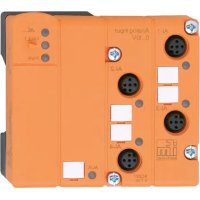
- Contents
- Powerlink 59
- Maintenance, repair and disposal 69
- Cleaning the housing surface....69
- Appendix 70
- Powerlink 79
- Preliminary note
- Symbols used
- Warnings used
- ATTENTION
- CAUTION
- WARNING
- Change history
- Safety instructions
- Cyber security
- Safety symbols on the unit
- Intended use
- Function
- IO-Link
- IO-Link supply
- Parameter setting
- Powerlink
- ifm IoT Core
- Visual indication
- Digital inputs
- Installation
- Install device
- Electrical connection
- Overview
- General wiring information
- General notes on wiring
- Feldbus ports
- IoT port
- IO-Link ports (Class A)
- Connecting IO-Link devices (Class A)
- Connecting IO-Link devices (Class B)
- Ground connection
- Voltage supply
- Operating and display elements
- LEDs
- Status
- Ethernet
- Voltage supply
- IoT
- IO-Link ports (Class A)
- Set-up
- Settings
- Configuration tools
- Supported configuration tools
- Getting started
- Requirements:
- IoT interface
- IoT: Configuring IP settings
- IoT: Configuring security mode
- IoT: Configuring access rights
- IoT: Configuring the interface to the monitoring software
- Fieldbus interface
- Fieldbus: Configuring the interface
- Ports
- Ports: Setting the data transmission to the monitoring software
- Ports: Setting the operating mode Pin 4 (US)
- Ports: Setting validation and data storage
- Ports: Setting the cycle time
- Info
- Info: Displaying the device information
- Firmware
- Firmware: Showing the firmware version
- Firmware: Resetting the device
- Firmware: Rebooting the device
- IO-Link devices
- ifm IoT Core
- ifm IoT Core: General information
- Accessing the ifm IoT Core
- GET method
- Example: GET request
- POST method
- Example: POST request
- Diagnostic codes
- Getting started
- General functions
- Example: Reading properties of an element
- Example: Outputting the subtree
- Example: Changing a parameter value
- Example: Reading several elements sequentially
- Example: Browsing device description
- DNS support
- Example: Using DNS support
- Example 2: subscribe
- IoT
- Example: Activating security mode
- Activating security mode
- Setting the password
- Example: Request with authentication
- Example: Resetting the password
- IoT: interface to moneo, configuring LR AGENT and LR SMARTOBSERVER
- Fieldbus
- Fieldbus: Configuring the POWERLINK interface
- Ports
- Ports: Configuring the device validation and data storage
- Example: Cloning the data memory of an IO-Link port
- Read data memory
- Restore data memory
- Ports: Configuring the data transfer to LR AGENT / LR SMARTOBSERVER
- Ports: Reading / writing process data
- Example: Reading an IO-Link process value (operating mode "IO-Link")
- Example: Writing an IO-Link process value
- Example: Reading the digital input value (operating mode "DI")
- Example: Writing the digital output value (operating mode "DO")
- Ports: Reading port events
- IO-Link devices
- IO-Link devices: Accessing parameters
- Example: Reading a parameter value of an IO-Link device
- Example: Writing a parameter value of an IO-Link device
- IO-Link devices: Reading and writing device information
- IO-Link devices: Reading IO-Link events
- Gateway
- Gateway: Resetting, rebooting and localising the device
- Gateway: Reading device information
- Gateway: Reading status and diagnostic information
- Notifications
- Event-controlled notifications
- Time-controlled notifications
- Example: Subscribing to notifications
- Solution:
- Example: Changing a notification
- Example: Subscribing to a notification in CSV format
- Example: Unsubscribing from a notification
- Example: checking a notification
- WebSocket support
- Example: Using WebSockets
- MQTT support
- Configuring the MQTT connection
- Configuring the MQTT command channel
- Example: Configuring the MQTT command channel
- Example: Publishing the temperature to an MQTT broker
- ifm IoT Core Visualizer
- Starting the ifm IoT Core Visualizer
- Managing notifications
- Creating a new notification
- Deleting a notification
- Searching for elements in the device description
- Configuring the IO-Link master
- Accessing process data
- Updating the firmware
- Powerlink
- General information
- Installing the XDD file
- Gateway
- Configuring access rights
- Configuring the Powerlink interface
- Reading device information
- Resetting the device
- Using the localisation function
- Ports
- Configuring the ports
- Setting fail-safe values for outputs
- IO-Link devices
- Accessing parameters of the IO-Link devices
- Example: Acyclic reading of parameters
- Example: Acyclic writing of parameters
- Setting information parameters of the connected IO-Link devices
- Process data
- Configuring TxPDO
- Example: Configuring TxPDO
- Solution: Configure TxPDO.
- Configuring RxPDO
- Example: Configuring RxPDO
- Events
- Reading IO-Link events
- Maintenance, repair and disposal
- Cleaning the housing surface
- Appendix
- ifm IoT Core
- Profiles
- Types
- Services
- Service: factoryreset
- Service: getblobdata
- Service: getdata
- Service: getdatamulti
- Service: getelementinfo
- Service: getidentity
- Service: getsubscriberlist
- Service: getsubscriptioninfo
- Service: gettree
- Service: install
- Service: iolreadacyclic
- Service: iolwriteacyclic
- Service: querytree
- Service: reboot
- Service: reset
- Service: setblock
- Service: setdata
- Service: signal
- Service: start
- Service: start\_stream\_set
- Service: stop
- Service: stream\_set
- Service: subscribe
- Service: unsubscribe
- Service: validation\_useconnecteddevice
- Powerlink
- Object directory
- Legend:
Brand : IFM
Model : AL1373
Category : Processor