
ERX-3500 - Elliptical bike Toorx - Free user manual and instructions
Find the device manual for free ERX-3500 Toorx in PDF.


| Product Type | Elliptical Trainer |
| Brand | Toorx |
| Model | ERX-3500 |
| Dimensions (L x W x H) | Approx. 150 x 70 x 170 cm |
| Net Weight | Approx. 60 kg |
| Max User Weight | 120 kg |
| Power Supply | Battery operated (2x AA, not included) |
| Display Type | LCD with time, distance, speed, calories, pulse |
| Resistance System | Magnetic, adjustable (8 levels) |
| Flywheel Weight | 8 kg |
| Pedal Material | Anti-slip plastic with adjustable straps |
| Handlebars | Fixed and moving, with pulse sensors |
| Transport Wheels | Yes, front wheels for easy movement |
| Leveling Feet | Yes, adjustable for stability |
| Programs | 12 preset programs + manual mode |
| Heart Rate Monitor | Hand grip sensors |
| Maintenance | Keep clean, lubricate moving parts every 3 months |
| Safety Key | Emergency stop with magnetic tether |
| Spare Parts Availability | Contact Toorx customer service or authorized dealers |
| Warranty | 2 years for parts, 1 year for labor |
Frequently Asked Questions - ERX-3500 Toorx
User questions about ERX-3500 Toorx
0 question about this device. Answer the ones you know or ask your own.
Ask a new question about this device
Download the instructions for your Elliptical bike in PDF format for free! Find your manual ERX-3500 - Toorx and take your electronic device back in hand. On this page are published all the documents necessary for the use of your device. ERX-3500 by Toorx.
USER MANUAL ERX-3500 Toorx
natural_image
Exterior view of a modern stationary exercise machine (no text or symbols visible)iConsole App Manual

www.toorx.it/iconsole
ERX3500

natural_image
Simple line drawing of a triangle with an open book symbol inside, no text or labels present.CHECK LIST (CONTENTS OF PACKAGE):
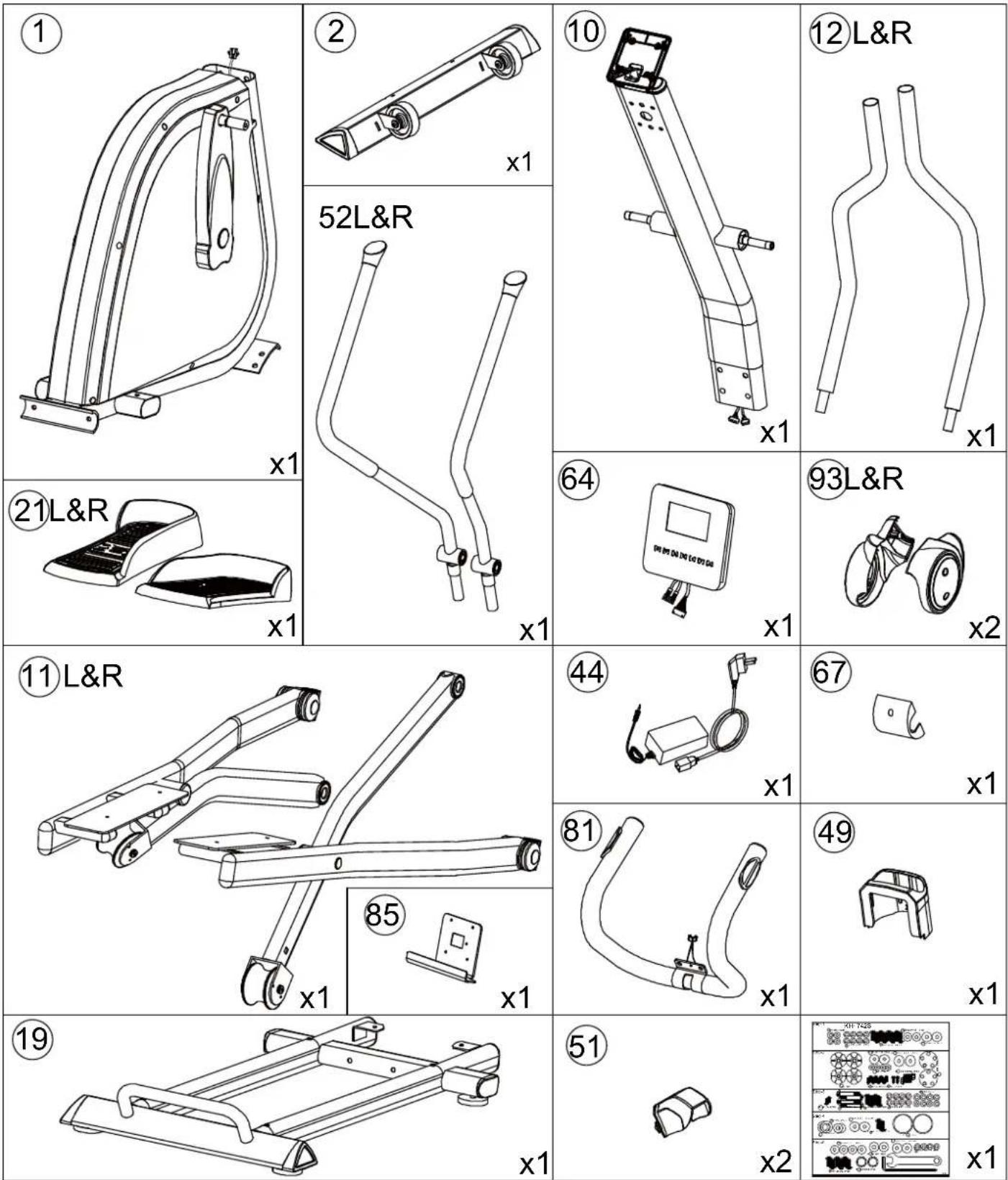
Exploded drawing:
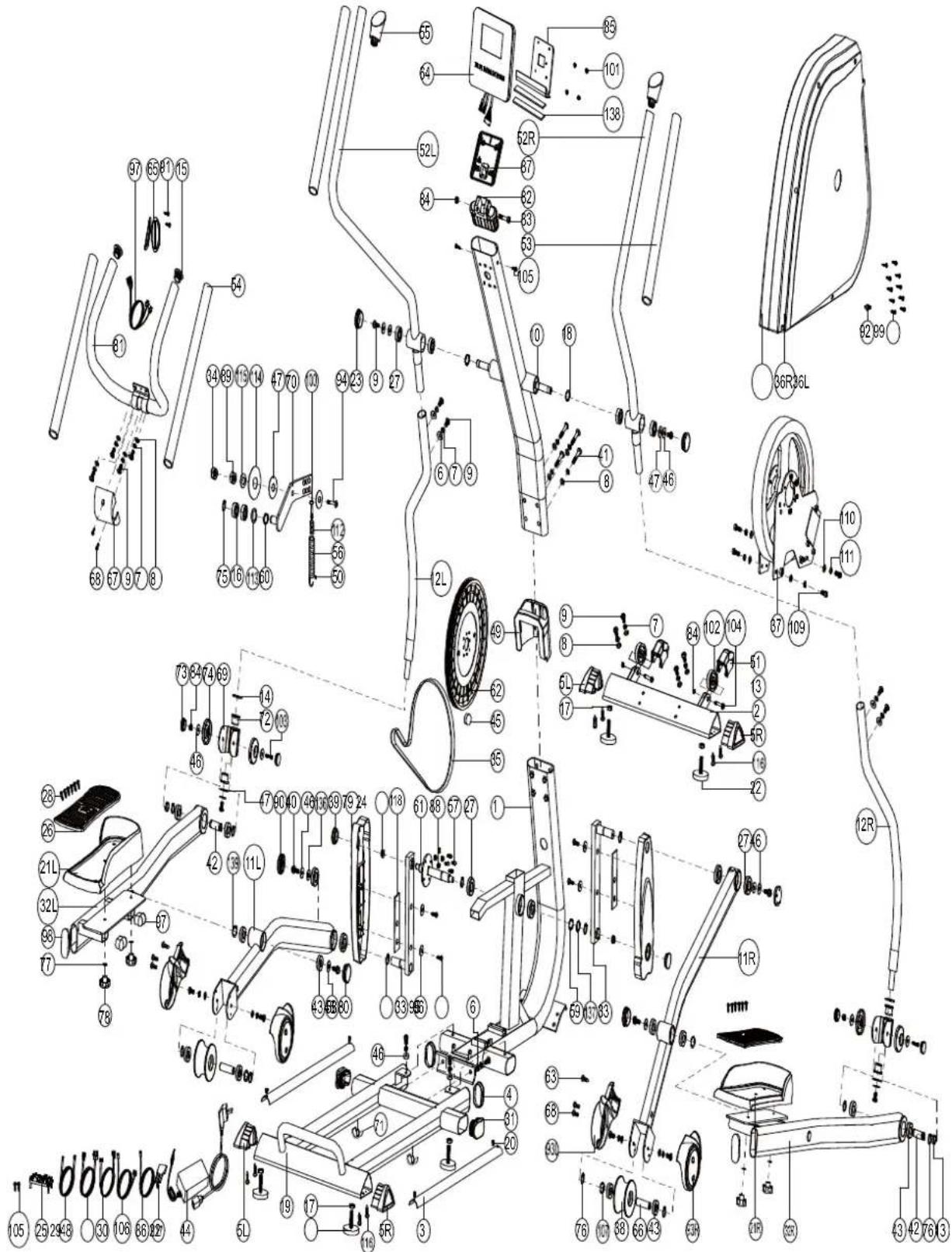
Part List:
| Part NO. | Description Material Specification QTY | |||
| 1 Main frame 1 | ||||
| 2 Front stabilizer 1 | ||||
| 3 Sliding beam guiding plate Q235A R19.1*681*1.5T 2 | ||||
| 4 Oval cap P.E. 40*60*11L | 2 | |||
| 5L | Tri-angle cap(left) | PE | 95.7*57.2*51.3 | 2 |
| 5R | Tri-angle cap(right) | PE | 95.7*57.2*51.3 | 2 |
| 6 | Curved washer | Q235A | D22xD8.5x1.5T | 6 |
| 7 | Spring washer | 70# | D15.4 XD8.2x2T | 24 |
| 8 | Flat washer | Q235A | D16*D8.5*1.2T | 16 |
| 9 | Allen bolt | 35# | M8x1.25x20L,8.8 | 22 |
| 10 Handlebar post 1 | ||||
| 11L | Supporting tube for left pedal | 1 | ||
| 11R | Supporting tube for right pedal | 1 | ||
| 12L | Supporting tube for left movable handlebar | 1 | ||
| 12R | Supporting tube for right movable handlebar | 1 | ||
| 13 | Spacer | NL66 | D21*D17.1*5T | 2 |
| 14 | Waved washer | 65Mn | D26*D19.5*0.3T | 2 |
| 15 | Mushroom cap | PVC | D1 1/4"*29L | 2 |
| 16 | Bearing | GCr15 | #99502 | 2 |
| 17 | Hex nut Q235A | M10*1.5*8T | 6 | |
| 18 | Plastic washer | NL66 | D29*D20*0.9T | 2 |
| 19 | Sliding beam welding set | 1 | ||
| 20 | Bolt | Q235A | M6*1*15L | 4 |
| 21L | Left pedal | PP | 410.7*173.9*70 | 1 |
| 21R | Right pedal | PP | 410.7*173.9*70 | 1 |
| 22 | Adjustable round wheel | Q235A | D38*M10*1.5 | 6 |
| 23 | Round cap | PE | D50x15L | 2 |
| 24 | Anti-loose nut | 35# | M10*1.25*7T | 2 |
| 25 | Control board | EMS2500-A01 | 1 | |
| 26 | Pedal pad | TPU45+HIPS | 354.9*134.5*9 | 2 |
| 27 | Bearing | #6004ZZ | 10 | |
| 28 | Screw | 10# | ST4*1.41*14L | 12 |
| 29 | Upper computer cable | 1000L | 1 | |
| 30 | Lower computer cable | 450L | 1 | |
| 31 | Cap | PE | 40*80*33 | 2 |
| 32L | Bracket for left pedal | 1 | ||
| 32R | Bracket for right pedal | 1 | ||
| 33 | Crank welding set 2 | |||
| 34 | Nut Q235A M8*1.25*8T 1 | |||
| 35 | Poly belt 450 PJ6 1 | |||
| 36L | Left chain cover | PS | 698.8*597*71.9 | 1 |
| 36R | Right chain cover | PS | 698.8*597*67.5 | 1 |
| 37 | Magnetic system | D265*86 | 1 | |
| 38 | Wheel | PU | D87.2*55L | 2 |
| 39 | Side cap | PVC | D36x14 | 2 |
| 40 | Hex bolt | 35# | M8*1.25*20L | 6 |
| 41 | Allen bolt | 35# | M8*1.25*50L,8.8 | 4 |
| 42 | Axle | Q235A D17*48L | 2 | |
| 43 | Bearing | GCr15 | #6003ZZ | 12 |
| 44 | Adaptor | Output: 26V,2.3A | 1 | |
| 45 | Round magnet | M02 | 1 | |
| 46 | Flat washer | Q235A | D25*D8.5*2T | 14 |
| 47 | Plastic washer | NL66 | D10*D24*0.4T | 6 |
| 48 | Connection cable | 500L | 1 | |
| 49 | Upper protective cover | HIPS | 137.1*121*73.4 | 1 |
| 50 Plastic cover | PVC | D3*30L | 1 | |
| 51 | Wheel cover | PP | 93.2*64.7*62 | 2 |
| 52L | Left movable handlebar | 1 | ||
| 52R Right movable handlebar | 1 | |||
| 53 | Foam NBR | D30x3Tx680L | 2 | |
| 54 | Foam NBR | D30x3Tx530L | 2 | |
| 55 | Handlebar cap | PVC | 95.8*50.8 | 2 |
| 56 | Spring | 72A# | D3*D19*67L 1 | |
| 57 | Hex bolt | 35# | M6x1.0x15L, 8.8 | 4 |
| 58 | C ring | 65Mn | D22.5*D18.5*1.2T | 4 |
| 59 | Waved washer | 65Mn | D27*D20.3*0.5T | 1 |
| 60 | Waved washer | 65Mn | D21xD16.2x0.3T | 1 |
| 61 | Crank axle welding set | 1 | ||
| 62 | Belt wheel | NL+ fiber | D305x19.5 | 1 |
| 63 | Screw | 10# | ST4*1.41*15L | 2 |
| 64 | Computer | SE-1699-31 | 1 | |
| 65 | Handle pulse | PE18 | 2 | |
| 66 | Axle of wheel | 35# | D17*61.2L | 2 |
| 67 | Protective cover | ABS | 100*81*40.8 | 1 |
| 69 Universal joint 2 | ||||
| 70 Idle wheel fixing plate 1 | ||||
| 71 Buffer SBR R23x35x43 2 | ||||
| 72 | Bushing | D19.15x(D25.6x32)x L(17+3) | 4 | |
| 73 | Side cap | PVC | D29.1*13L | 4 |
| 74 | Axle cover | PE6070 | D60*13.5L | 4 |
| 75 C ring 65Mn S-16(1T) | 1 | |||
| 76 C ring 65Mn S-17(1T) | 8 | |||
| 77 | Flat washer | Q235A | D14xD6.5x0.8T | 4 |
| 78 | Club knob ABS+CU | D40*M6*12 | 4 | |
| 79 | Crank cover | PS | 339*102.6*29.9 | 2 |
| 80 Round side cap PE | D45*15 | 2 | ||
| 81 | Handle bar welding set | 1 | ||
| 82 | Computer fixing plate | ABS | 120*40*70 | 1 |
| 83 | Screw | 35# | M8*1.25*45L 1 | |
| 84 | Nut | Q235A | M8*1.25*8T | 5 |
| 85 | Computer fixing plate | Q235A | 220*120*3T | 1 |
| 86 | Sensor cable | 250L | 1 | |
| 87 | Computer fixing bracket | ABS | 120*110*2.5T | 1 |
| 88 | Nut | Q235A | M6x1.0x6T | 4 |
| 89 | Hex nut | Q235A | M8*1.25*6T | 2 |
| 90 | Axle cover | PVC | D46*14.8 | 2 |
| 91 | Screw | Q235A | ST4x25L | 2 |
| 92 | Pin | ABS | D6*26.5*7.7 | 1 |
| 93L | Rear axle cover (left) | PS | 155*119.7*52.5 | 2 |
| 93R | Rear axle cover (right) | PS | 155*119.7*55.5 | 2 |
| 94 | Allen bolt | 35# | M8x1.25x30L ,8.8 | 1 |
| 95 | Screw | 10# | ST4*1.41*15L | 4 |
| 96 | Flat washer | Q235A | D15*D5.2*1.0T | 4 |
| 97 | Handle pulse cable | 700L | 2 | |
| 98 | Oval side cap | PE | 30*70*10.5 | 6 |
| 99 | Screw | 10# | ST4.2x1.4x20L | 10 |
| 100 | Allen bolt | 35# | M8*1.25*50L,8.8 | 1 |
| 101 | Bolt | 10# | M5*0.8*15L,8.8 | 4 |
| 102 | Wheel | PP | D65*24 | 2 |
| 103 | Screw | 35# | M8*1.25*75L,8.8 | 2 |
| 104 Allen bolt Q235A M8*1.25*40L,8.8 2 | |||
| 105 Screw 10# ST4.2x1.4x15L 4 |
| Part NO. | Description Material Specification QTY | |||
| 106 Electric cable 700L 1 | ||||
| 107 | Waved washer | 65Mn | D22xD17x0.3T 10 | |
| 109 Screw 35# | M6*1.0*15L,8.8 4 | |||
| 110 | Flat washer | Q235A | D13*D6.5*1.0T | 4 |
| 111 Spring washer 70# | D10.5*D6.1*1.3T 4 | |||
| 112 Nut | Fe D15*13L | 1 | ||
| 113 | Flat washer | Q235A | D24*D16*1.5T | 1 |
| 114 | Flat washer | Q235A | D50*D10*3T | 1 |
| 115 | Flat washer | Q235A | D28*D8.5*3T | 1 |
| 116 Screw 10# | ST4*1.41*12L 8 | |||
| 117 | Bolt | Q235A | M5*0.8*10L | 1 |
| 118 | Buffer | NBR | 20*90*1.7T | 2 |
| 136 | Buffer | PVC | D27*D8.2*2.5T | 2 |
| 137 | Flat washer | Q235A | D26*D21*1.5T | 1 |
| 138 | Buffer | EVA | 219*15*2T | 2 |
| 139 Spring washer NL66 | D27*D18*1.0T 2 | |||
| \ | Allen spanner 35# M6, 8.8 | 1 | ||
| \ | Spanner | Q235A | 139*5T | 1 |
STEP 1

1) Assemble the sliding beam welding set (19) to the main frame (1) by using the curved washer (6), the spring washer (7), the Allen bolt (9) and the flat washer (46).
2) Assemble the front stabilizer (2) to the main frame (1) by using the spring washer (7), the flat washer (8) and the Allen bolt (9).
3) Mount the wheel cover (51) to the wheel. And you can adjust the proper height by turning the wheel of foot cap.
STEP 2

1) Assemble the supporting tube (11L & 11R) to the crank welding set (33) by using the buffer (136), the flat washer (46), the hex bolt (40). Then assemble the axle cover (90) on the two outside as the fig. 2-1.
2) Assemble the pedal (21L & 21R) to the supporting tube (11L & 11R) by using the flat washer (77) and the club knob (78) as the fig. 2-2.
3) Assemble the rear axle cover (93L & 93R) to the supporting tube (11L & 11R) by using the screw (63), and the bolt (68) as the fig. 2-3.
STEP 3


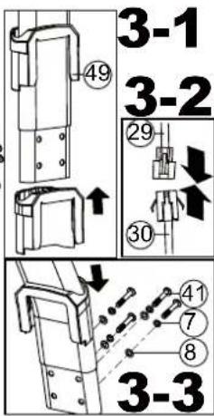

1) Suggest assembling this step by two persons.
2) First, lift up the upper protective cover (49) as fig. 3-1. Then connect computer cable (29 & 30) as fig.3-2.
3) Insert the handlebar post (10) on the main frame and tighten it by using the flat washer (8), the spring washer (7) and the Allen bolt (41). Place down the upper protective cover (49) and make it tight on the main frame as fig.3-3.
4) Assemble the handlebar welding set (81) to the handlebar post (10) by using the flat washer (8), the spring washer (7), and the Allen bolt (9) as fig.3-4.
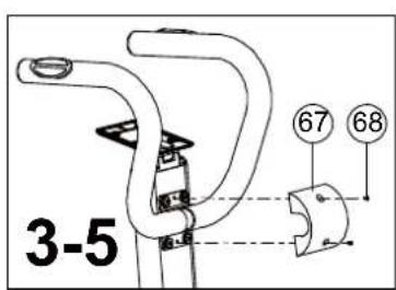
5) Assemble the protective cover (67) by using the bolt (68) as fig.3-5.
STEP 4
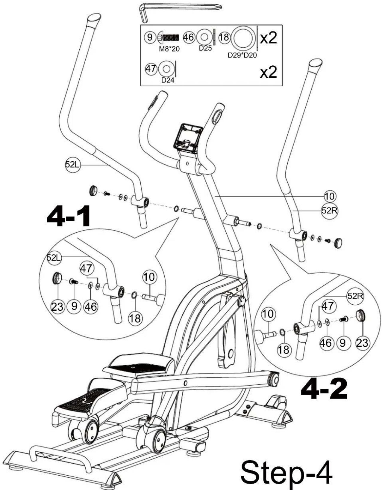
4) Assemble the left and right movable handlebar (52L&52R) on the handlebar post tube (10) by using the Allen bolt (9), the flat washer (46), the plastic washer (47) and the plastic washer (18). Then assemble the round side cap (23) on the two outside.
STEP 5
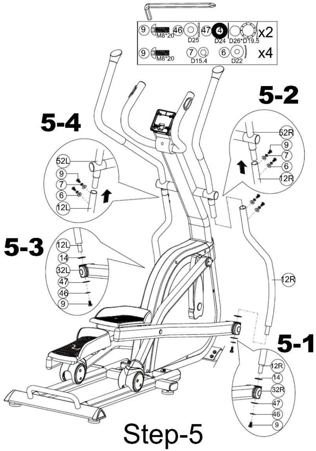
1) Assemble the left and right movable supporting tube (12L & 12R) to the bracket for pedal (32L & 32R) by using the Allen bolt (9), the flat washer (46), the plastic washer (47) and the waved washer (14) as fig. 5-1 & fig. 5-3.
2) Assemble the left and right movable handlebar (52L&52R) to the movable supporting tube (12L & 12R) by using the curved washer (6), the spring washer (7), and the Allen bolt (9) as fig. 5-2 & fig. 5-4.
STEP 6

1) Connect the upper computer cable (29) and the handle pulse cable (65) with the computer (64), then fix the computer (64) on the computer fixing plate (85)&the handlebar post &by using the bolt (101).
2) Connect the adaptor (44) to the adaptor input on the front of the bike.
INSTRUCTION MANUAL FOR COMPUTER
【BUTTON FUNCTION】
| UP To make upward adjustment or increase training resistance. | |
| DOWN To make downward adjustment or decrease training resistance. | |
| ENTER To confirm all settings. | |
| START/ STOP To start or stop workout. | |
| RESET To reset current settings or press to have monitor switching to initial training mode for renew selection. | |
| RECOVERY To test heart rate recovery status. | |
| BODY FAT To test body fat%.Press “BODY FAT” and hold for 2 seconds to modify user data (SEX/ AGE/ HEIGHT & WEIGHT) in standby mode. |
【DISPLAY FUNCTION】
| TIME | Count up - TIME will count up from 00:00 to maximum of 99:59 when there's no target time preset. Each increment is 01:00 minute.Count down - TIME will count down from preset target time to 00:00.Each preset increment or decrement is 01:00 minute with available range between 01:00 to 99:00. |
| SPEED Current training speed with maximum of 99.9 KM/H or 99.9 ML/H. | |
| RPM Rotation Per Minute with available range from 0~15 to 999. | |
| DISTANCE | Accumulation of total distance from 00:00 up to 99.99 KM or 99.99 ML. Use UP/ DOWN key to preset target distance with each upward adjustment of 0.1 KM or 0.1 ML. |
| CALORIES | Accumulation of total calories consumption during training from 0 to maximum of 9999 calories. (This data is a rough guide for comparison of different exercise sessions which cannot be used in medical treatments.) |
| PULSE User may set up target pulse from 0~30 to 230. Console system will have buzzer beeping as a cue when user's actual heart rate exceeds preset target value during workout. | |
| WATTS | Current workout watts with available range from 0 to 999. |
1.1 Plug in adaptor to power on console, system will have buzzer beeping as a cue.
1.2 LCD will have all segments displaying for two seconds along with "78.0" (wheel diameter), "E" (EU), and "K" (KM) for one second.

(2)USER PROFILE SET UP -
2.1 Use UP (☐) and DOWN (▼) key to select a user profile from U1\~U4, press "ENTER" to confirm when a user profile is selected.
2.2APress "ENTER" each time when value's determined for SEX, AGE, HEIGHT, and WEIGHT settings and all entered data will be saved in user profile U1\~U4.
(3)PROGRAM SELECTING –
3-1 Programs display on LCD as MANUALA12 PROGRAMSAH.R.C.AWATTAUSER→→→→
PROGRAMAMANUAL in sequence.→
3-2 Use UP (☐) and DOWN (▼) key to select a program and press "ENTER" to confirm when selection is determined.

(4) MANUAL -
4-1 Select "M" and use UP (☐) and DOWN (▼) key to adjust resistance level; press "ENTER" when value is determined.
4-2 Resistance level can be readjusted during workout.
4-3 LEVEL column will switch and display WATT value after three seconds of no resistance adjustment.
4-4 Use UP (☐) and DOWN (A) key for TIME, DISTANCE, CALORIES, and PULSE settings. Press ▼ "ENTER" each time when value's determined.
4-5 Press "START" and start pedaling. RPM & PULSE bars will display values accordingly.
4-6 Press "STOP" to pause exercise and all exercise values will be saved.
4-7 Press "RESET" and return to program selecting.

(5) 12 PROGRAMS -
5-1 Use UP (⊥) and DOWN (▼) key to select a program from P1 to P12 and press "ENTER" to confirm after selection's determined.
5-2 LCD will display corresponding flashing graphic to the program user selects.
5-3 Use UP (☐) and DOWN (▼) key to adjust resistance level and TIME; press "ENTER" each time when value's determined and press "START" to start workout.
5-4 Resistance level can be readjusted during workout.
5-5 LEVEL column will switch and display WATT value after three seconds of no resistance adjustment.

(6) H.R.C. -
6-1 Use UP (☐) and DOWN (▼) key to select 55%, 75%, 90%, or TARGET.
6-2 The heart rate value will be calculated automatically according to the AGE value user inputs and will be shown in the alphanumeric column in flashing text.
6-3 When user selects "TARGET", use UP (☐) and DOWN (▼) key to set value between 30\~230 and press "ENTER" to confirm when value's determined.
6-4 Use UP (☐) and DOWN (A) key to set TIME and press "ENTER" to start workout.

(7) USER PROGRAM -
7-1 Use UP ( ) and DOWN ( ) key to create user's desired program, press "ENTER" when each chart value's determined.
7-2 Press "ENTER" and hold for 2 seconds and skip to TIME setting.
7-3 Press "START" and user may start pedaling.

(8) WATT -
8-1 WATT default value 120 will be displayed in the alphanumeric column in flashing text waiting for an adjustment.
8-2 Use UP (☐) and DOWN (A) key to adjust WATT and TIME values.
8-3 Press "START" to start exercise.
8-4 WATT LEVEL will be adjusted automatically according to user's actual RPM input value.
8-5 WATT LEVEL can be readjusted manually during workout.

(9) BODY FAT -
9-1 This function is valid after user stops pedaling (or press "STOP").
9-2 A continuous RPM signal input is required during BODY FAT test.
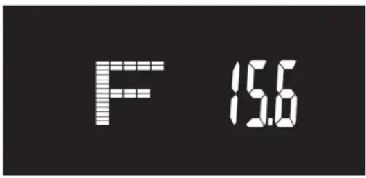
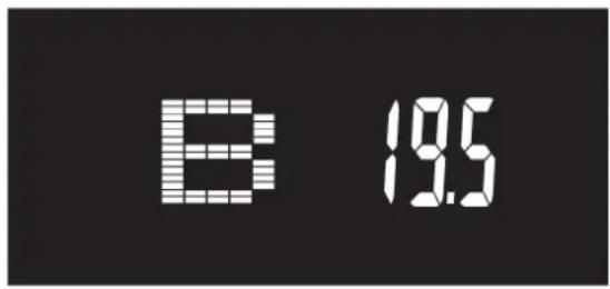
9-3 Press "BODY FAT", console system will display "UX" for two seconds and start the body fat measurement process and will show results of FAT% and BMI on screen 8 seconds later.
9-4 Press "BODY FAT" and hold for two seconds to enter user profile to reset SEX, AGE, HEIGHT, and WEIGHT. Press "ENTER" to start body fat measurement process.
9-5 If LCD displays following messages:
"E-1"- When there's no heart rate signal input detected; or "E-4" - When FAT% result exceeds 5\~50 and BMI result exceeds 5\~50.
(10) RECOVERY -
10-1 RECOVERY function is valid when there's a heart rate value input detected (during exercise or after user presses "STOP").
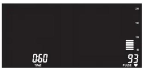
10-2 Press "RECOVERY" and LCD will display TIME "0:60" counting down with user's actual heart rate value showing in the PULSE column.
10-3 When TIME reaches to "0:00", LCD will have result "FX" (X=1\~6) displaying in the alphanumeric section.
10-4 Press "RECOVERY" again and return to previous mode during or after RECOVERY test's occurred; LCD will continue displaying user's actual heart rate value on screen.

APP:


Download on the App Store

- This console has been built in Bluetooth 4.0 module for APP function.
- Once console is connected to smart device via Bluetooth, the console will power off.
Noted:
- After 4 minutes without pedaling or pulse input, console will enter into power saving mode. Press any key may wake the console up.
- If console operation or display abnormally, please Power-off and restart it.

Garlando
GARLANDO SPA
Via Regione Piemonte, 32 - Zona Industriale D1
15068 - Pozzolo Formigaro (AL) - Italy
contact@toorxprofessional.it
www.toorxprofessional.it

Brand : Toorx
Model : ERX-3500
Category : Elliptical bike