
Thunder Sports MUDRZRDK - Audio MTX Audio - Free user manual and instructions
Find the device manual for free Thunder Sports MUDRZRDK MTX Audio in PDF.


| Product Type | Audio System Kit (Dash Kit + Media Controller + Speakers) |
| Brand | MTX Audio |
| Model | Thunder Sports MUDRZRDK (Dash Kit) with AWMC3 and RZRPOD65 |
| Display | 3" Full Color TFT Display |
| Tuner | AM / FM / WB with SiriusXM-Ready |
| Bluetooth | Audio Streaming (A2DP) |
| Amplifier Power | Internal 4 x 50 Watts Peak |
| Power Supply | 12V DC (10.8-15.6V allowable) |
| Fuse Rating | 20A |
| Weather Resistance (Media Controller) | IP66 – Dust and Water Resistant |
| Speaker Power Handling (RMS) | 65 Watts per Speaker |
| Speaker Peak Power | 130 Watts per Speaker |
| Speaker Sensitivity | 95 dB (2.83V/1m) |
| Speaker Frequency Response | 85 Hz – 22 kHz |
| Speaker Impedance | 4 Ohms |
| Audio Inputs | AUX, USB, Bluetooth, SiriusXM (Tuner required) |
| Audio Outputs | 2 Sets of Preouts (Front/Rear) |
| Vehicle Compatibility | Polaris RZR XP / XP4 1000 (2014+), Turbo (2016+), 900/900S/1000S (2015+) |
| Installation (Speakers) | No cutting or drilling required |
| Included Components | Dash Kit, Media Controller, Pair of Speakers, Mounting Hardware |
| Mounting Hole (Media Controller) | 3 inches (77 mm) diameter |
Frequently Asked Questions - Thunder Sports MUDRZRDK MTX Audio
User questions about Thunder Sports MUDRZRDK MTX Audio
0 question about this device. Answer the ones you know or ask your own.
Ask a new question about this device
Download the instructions for your Audio in PDF format for free! Find your manual Thunder Sports MUDRZRDK - MTX Audio and take your electronic device back in hand. On this page are published all the documents necessary for the use of your device. Thunder Sports MUDRZRDK by MTX Audio.
USER MANUAL Thunder Sports MUDRZRDK MTX Audio
OWNER'S MANUAL
MUDRZRDK
POLARIS® RZR® DASH KIT
[FOR USE WITH MTX WET-MC3 HEAD UNIT]
IMPORTANT NOTICE
If you have any questions regarding wire routing in a vehicle, please contact MTX Technical Support at 1-800-225-5689.
When connecting power and ground wires ensure that the red power wire is fused at the point where it is connected to the vehicle's battery. Failure to do so can result in damage to the vehicle if a short circuit develops between the vehicle connection point and the product.
PRODUCT INFORMATION
| Model # |
| Serial # |
| Dealer's Name |
| Date of Purchase |
IN THE BOX
- Dash Kit
- Allen Wrench
• (2) Shoulder Head Bolts
• (2) Speed Clips
• (4) Mounting Nuts
INSTALLATION TOOLS
The following is a list of suggested tools needed for installation:
- Torx - T40
• 5.5mm Nut Driver or Socket Wrench
• Pry Tool or Small Flat Blade
INTRODUCTION
Thank you for purchasing this Polaris® RZR® Dash Kit designed for the MTX Audio WET-MC3 Bluetooth all-weather head unit. This easy to install dash kit is the perfect OEM fit solution for your Polaris® RZR®. Congratulations and enjoy the ultimate audio experience with MTX!
FITS THE FOLLOWING VEHICLES
• RZR® XP / XP4 1000 (2014 and up)
• RZR® XP / XP4 Turbo (2016 and up)
- RZR® XP / XP4 900 (2015 and up. Must purchase storage pocket from Polaris® for a 2014 and up RZR® XP / XP4 1000 to utilize this dash kit on the 2015 and up RZR® XP / XP4 900 models.)
SPECIFICATIONS

INSTALLATION
Step 1 - Release the two quick locks to remove the hood from the vehicle.

Step 2 - Lift up the hood and slide towards the front of the vehicle.

Step 3 - Remove the two (2) T40 screws holding down the top dash cover.

Step 4 - Lift and pull back the top dash cover to release the clips holding it in place. Unplug the gauge and switches making sure not to damage the vehicle and ignition wiring. Make note to remember what connector is associated with each specific switch.

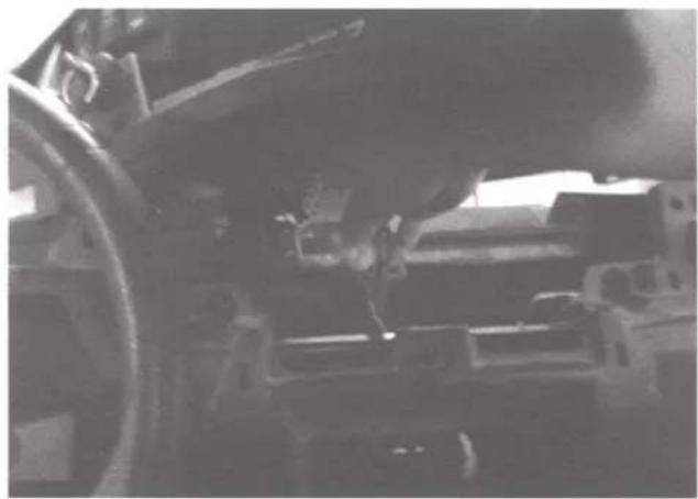
Step 5 - Remove the Torx head screw from the dash pocket brace. After this is removed the plastic dash pocket can be pulled out of the dash.

Step 6 - Remove the center pocket after it has been disconnected from the brace.

Step 7 - Turn the center pocket upside down to access the protective cover pins. Pry the two pins loose using a pry tool to remove the cover.
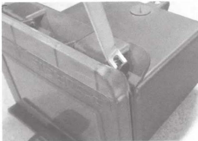
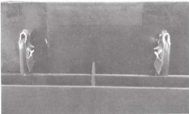
Step 8 - Slide the two included speed clips onto the rear of the dash piece.

Make sure the speed clips are orientated according to the picture below.
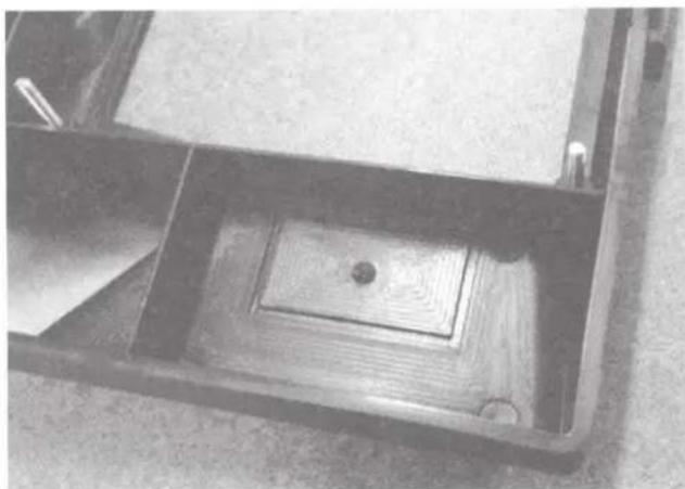
Step 9 - This dash kit also offers additional space to mount up to two rocker panel switches for accessories. On the rear of the dash kit, grooves are provided to give you proper location and size for mounting additional switches.
Step 10 - Before mounting the source unit to the dash kit, make sure that the trim bezel that is included with the source unit is NOT attached. If it is attached, it will need to be removed. It will NOT be used.
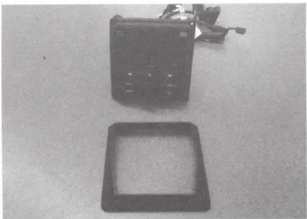
Step 11 - Attach the source unit to the rear of the dash kit using the included nuts.

Step 12 - One of the circular knockout panels on the rear of the pocket will need to be removed to provide an access hole to route wiring from the source unit to the vehicle.

Step 13 - Attach the dash kit to the center pocket by first inserting the wiring into the pocket. Connect the wiring to the source unit and feed the wiring out of the rear of the pocket hole that was cut. Place the dash kit onto the front of the pocket.

Step 14 - Insert the tab on top of the dash kit into the slot on the pocket.

Step 15 - Once the dash kit is locked in, use the two included shoulder bolts to attach the bottom of the dash kit to the pocket.

NOTE: Make sure the speed clips used in Step 8 are lined up correctly or the bolts will not be able to be tightened.
Step 16 - Slide the dash kit, source unit and wiring back into the dash.
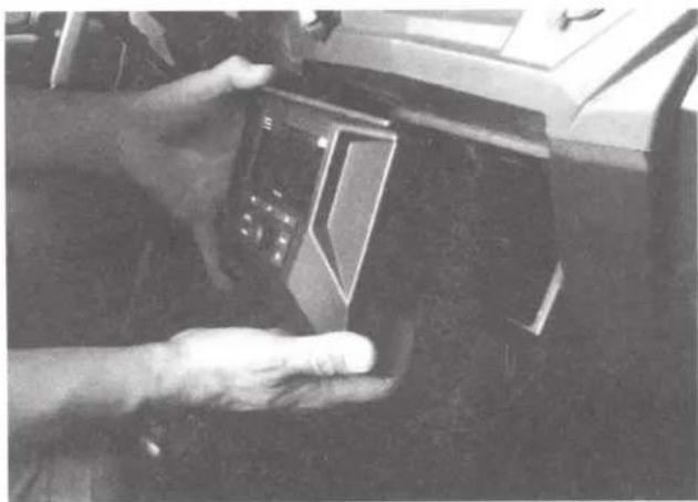
Step 17 - Reattach the rear support bracket to the pocket. Once rear brace is secure, the dash kit is installed and the vehicle can be put back together.

© 2016 Mitek Corporation. All rights reserved. MTX, Mud Nation, and Let's Do Something Dirty are trademarks of Mitek Corporation. All other trademarks are property of their respective owners. Designed and Engineered in the U.S.A.
Due to continual product development, all specifications are subject to change without notice.
MTX Audio, 4545 East Baseline Rd. Phoenix, AZ 85042 U.S.A. 1-800-225-5689
MTX005499 RevA 6/16 • 21A10514 • AW0015315

AWMC3
ALL-WEATHER MEDIA CONTROLLER WITH 3" DISPLAY
OWNER'S MANUAL

Made for
iPhone

Bluetooth™
((Siriusxm))
IMPORTANT NOTICE
If you have any questions regarding wire routing in a vehicle, please contact MTX Technical Support at 1-800-225-5689.
When connecting power and ground wires ensure that the red power wire is fused at the point where it is connected to the vehicle's battery. Failure to do so can result in damage to the vehicle if a short circuit develops between the vehicle connection point and the product.
PRODUCT INFORMATION
Model #
Serial #
Dealer's Name
Date of Purchase ____
IN THE BOX
• All-Weather Media Controller
- Mounting Plate
• U-Shape Mounting Bracket
• (4) M3.5 x 30MM Machine Screws
• (4) M4 Hex Nuts
INTRODUCTION
Thank you for purchasing this MTX Audio all-weather media controller that is designed to work with most Bluetooth enabled devices including iPhone® and Android® smartphones and tablets. This easy to install and use head unit is capable of transforming your Bluetooth enabled mobile device into the center of your vehicle's audio system. Congratulations and enjoy the ultimate audio experience with MTX!
FEATURES
• 3" Full Color TFT Display
SiriusXM-Ready™ (SiriusXM Connect Vehicle Tuner and Subscription Sold Separately)
• AM / FM / WB Tuner
- Bluetooth Audio Streaming
• Internal 4 x 50 Watt Power Amplifier
- AUX Input
- USB Charging
- iPhone® - Unit Will Charge and Play Music Through USB
- Android® - Unit Will Charge, but Will Not Play Music Through USB
- Unit Will Play Music and Display Album Artwork Using a USB Memory Stick (.mp3)
• Weather Resistant (IP66)
- Selectable EQ
• 2 Sets of Preouts (Front / Rear)
- Backlit Control Buttons
![graph TD A["Power / Speaker Connector"] --> B["FUSE 20A"] A --> C["SXM (SiriusXM Connect Tuner Sold Separately)"] A --> D["Black"] A --> E["AUX In"] A --> F["Grey"] A --> G["Line Out (Front)"] A --> H["Brown"] A --> I["Line Out (Rear)"] A --> J["Antenna"] A --> K["DIN"] A --> L["USB"]](/content/2026/05/932418/images/a1469c5f66898e4c1aa5f13d150c0271409ce458391eb4dda670f5617a03e206.jpg)
POWER AND SPEAKER CONNECTION
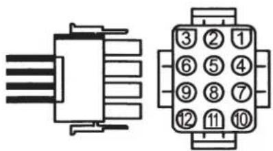
| Pin # | Wire Color | Wire Definition |
| 11 | White / Black | Front Left Speaker (-) |
| 12 | White | Front Left Speaker (+) |
| 6 | Green / Black | Rear Left Speaker (-) |
| 1 | Green | Rear Left Speaker (+) |
| 5 | Grey | Front Right Speaker (+) |
| 4 | Grey / Black | Front Right Speaker (-) |
| 9 | Purple | Rear Right Speaker (+) |
| 8 | Purple / Black | Rear Right Speaker (-) |
| 2 | Blue | Remote Output |
| 7 | ||
| 10 | Yellow | Battery (Fuse 20A) |
| 3 | Black | Ground |
INSTALLATION
Mounting (Using Mounting Plate)
To mount the unit, find a flat surface with adequate clearance behind it that provides enough room for the unit and all it's necessary wiring.
- Once a mounting location has been determined, cut a circular hole 3" (77mm) in diameter.
- After the hole is cut, slide the unit and wiring through the hole. A piece of self adhesive EVA foam is supplied in order to create a water resistant seal. This may be placed on the back side of the unit if desired.
- Slide the mounting plate over the backside of the unit and secure with the supplied screws.
- Press on the trim bezel to the front side of the unit.
- Plug in all wiring harnesses and cables. Refer to the wiring diagram for wire harness connection types.

Mounting (Using U Shape Bracket)
To mount the unit, find a flat surface with adequate clearance behind it that provides enough room for the unit and all it's necessary wiring.
- Once a mounting location has been determined, cut a circular hole 3" (77mm) in diameter.
- After the hole is cut, slide the unit and wiring through the hole. A piece of self adhesive EVA foam is supplied in order to create a water resistant seal. This may be placed on the back side of the unit if desired.
- Slide the U bracket over the two studs on the back of the unit. Tighten down with supplied nuts.
- Press on the trim bezel to the front side of the unit.
- Plug in all wiring harnesses and cables. Refer to the wiring diagram for wire harness connection types.

INSTALLATION
Mounting (Using Optional Vehicle Specific Dash Mount Kit - Sold Separately)
The unit will be mounted to each vehicle differently. Make sure to following the vehicle specific directions that were included with the dash kit.
- Slide the two included speed clips onto the rear of the dash kit.
- The dash kit may include additional space to mount rocker panel switches for accessories. On the rear of the dash kit, grooves will be provided to give proper location and size for mounting additional switches.
- Before mounting the source unit to the dash kit, make sure that the trim bezel that is included with the source unit is NOT attached. If it is attached, it will need to be removed. It will NOT be used.
- Attach the source unit to the rear of the dash kit using the included nuts.


CONTROLS
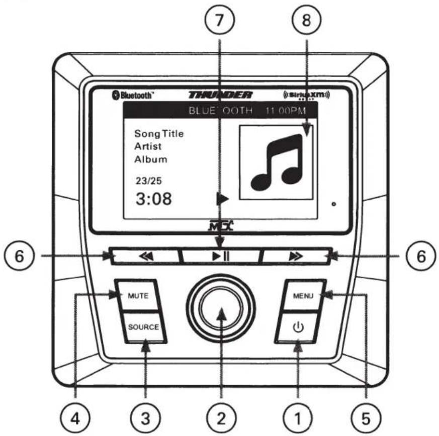
- Power Button (⏻) - This push button (On / Off) supplies power to the head unit.
- Volume / Function Control Knob - Rotate knob to set values and control volume. Press and hold knob for 3 seconds to access EQ menu and confirm function values.
- Source Button - This push button switches between audio sources. Use the Function Control Knob (2) to change and confirm selections.
- Mute Button - This push button mutes the audio.
- Menu Button - This push button accesses the Radio / Bluetooth / Sirius XM settings. Hold the Menu button to access the General settings. Tap the Menu button while in a menu to exit the current menu.
- Previous / Next Buttons ( «/ » ) - These push buttons switch between the previous and next tracks and radio stations.
- Play / Pause Button (▶II) - This push button will play and pause the audio. While in FM / AM / Sirius XM mode, the push button will access the FM1 / FM2 / FM3 / AM1 / AM2 / SXM1 / SXM2 / SXM3 bands.
- LCD Display
GENERAL OPERATIONS
Switching On and Off
Press Power Button (①) to turn the device On. Hold Power Button (②) to turn the device Off.
Operating Mode
Press Source Button to switch between radio reception (AM / FM / WB / SXM), audio input (AUX), USB and Bluetooth audio streaming (BT MUSIC). Rotate the VOL knob to change selections and press VOL knob to enter operating mode.
Volume
Rotate VOL knob to set the volume.
Sound Settings
Hold VOL knob for 3 seconds to enter EQ.
EQ options:
- Rotate VOL knob to select a between a variety of preset modes (Custom, Classic, Jazz, Rock, Pop, Optimal). In Custom mode, press the VOL knob to select the frequency band (it will be highlighted). Rotate the knob to adjust the level, to the desired amount. Too much boost will cause distortion.
- Press Menu Button to confirm.
Mute
Press the Mute Button to mute the audio output. Press the mute button again to unmute the audio.
General Setting
- Hold Menu Button for 2 seconds to access the General Settings.
- Rotate VOL knob to the option to be selected. Press the VOL knob to enter.
-
Clock Mode - Rotate VOL knob to switch between 12H and 24H. Press VOL knob to confirm.
-
Clock Adjust - Hours and Minutes can be selected by rotating the VOL knob. Pressing the VOL knob will select the HR or MIN and the value can then be changed by rotating the knob. Pressing the knob will confirm the setting. Press the Menu Button to exit from clock settings.
-
Back Light - Rotate VOL knob to Back Light. Press VOL knob to enter. Rotate VOL knob right to switch between Low / Mid / High / Auto lighting.
-
Fade and Balance - Rotate VOL knob to Fade or Balance and press to confirm. Rotate VOL knob to adjust. Pressing the VOL knob a second time confirms setting and switches to the other setting (fade/balance). Rotating the knob adjusts the second setting. Press the Menu Button to exit.
-
EQ - Press VOL knob. Rotate VOL knob to EQ Setup. Press VOL knob to enter. Rotate VOL knob to select a variety of preset modes. Press VOL knob to confirm. Press the Menu Button to exit the EQ setup.
-
Version - Rotate VOL knob to Version. Press VOL knob to view the current DECODE Version and MCU Version.
-
Factory Reset - Rotate VOL knob to Factory Reset. Press VOL knob to select. Rotate to YES or NO. Press VOL knob on YES to reset to factory default.
- Press the Menu Button to exit General Menu.

RADIO FUNCTIONS
Selecting Radio Band
- Press Source Button and rotate VOL knob.
- Press VOL knob to select radio band.
- Select FM or AM band.

Automatic or Manual Search Frequencies
- Press and hold the Previous / Next Buttons ( « / » ) to start automatic station search. The search stops when a station is found.
- Press the Previous / Next Buttons ( «/» ) briefly to change the frequency until the desired frequency is set.
Storing Frequencies (6 Presets per FM/AM Band)
- Press Menu Button to enter FM Settings. Rotate VOL knob to select Save Presets. Press the VOL knob to confirm. A list of presets will be shown. Rotate VOL knob to the desired preset. Press the VOL knob to enter the preset.
Note: Press Play / Pause Button (▶II) to select FM1 / FM2 / FM3 or AM1 / AM2.

Recalling Frequencies
- Press Menu Button to enter FM Settings. Rotate VOL knob to select Presets.
- Press the VOL knob. A list of presets will be displayed.
- Rotate the VOL knob to the desired preset. Press the VOL knob to switch to the selected preset.
- FM Band - Press Menu Button, and rotate to FM band. Press VOL knob to select. FM1, FM2, FM3 or AM1, AM2 will be displayed. Rotate the VOL knob to the desired selection and press the VOL knob to select.
- Auto Store - Press Menu Button and rotate to Auto Store. Press VOL knob to select. The radio will scan and save the 6 strongest stations into the preset memory.
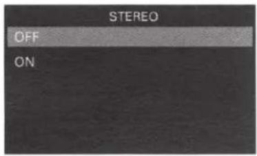
- Stereo - Press Menu Button and rotate to Stereo. Press VOL knob to select. On / Off will be displayed to turn stereo tuning ON or OFF.
RADIO FUNCTIONS
Local
- Press Menu Button to enter FM Settings.
- Press VOL knob and rotate to select Local.
- Press VOL knob and rotate to select Local ON / OFF.
Note: Only stations with good reception quality will be played under the Local setting.
Select USA / Europe Area Frequencies
- Press Menu Button to enter FM Settings.
- Press VOL knob and rotate to select Radio Region.
- Press VOL knob and rotate to select USA / Europe Frequencies.
SiriusXM® OPERATION
Only SiriusXM® brings you more of what you love to listen to, all in one place. Get over 140 channels, including commercial-free music plus the best sports, news, talk, comedy and entertainment. Welcome to the world of satellite radio. A SiriusXM Vehicle Tuner and Subscription are required. For more information, visit www.siriusxm.com.
After installing your SiriusXM Connect Vehicle Tuner and antenna, power on your AWMC3 and select SiriusXM mode. You should be able to hear the SiriusXM preview channel on Channel 1. If you cannot hear the preview channel, please check the installation instructions to make sure your SiriusXM Connect tuner is properly installed.
After you can hear the preview channel, tune to Channel 0 to find the Radio ID of your tuner. In addition, the Radio ID is located on the bottom of the SiriusXM Connect Vehicle Tuner and its packaging. You will need this number to activate your subscription. Write the number down for reference.
Note: the SiriusXM Radio ID does not include the letters I, O, S or F.
In the USA, you can activate online or by calling SiriusXM Listener care:
- Visit www.siriusxm.com/activatenow
• Call SiriusXM Listener Care at 1-866-635-2349
For Canadian Subscriptions, please contact:
- Visit www.siriusxm.ca/activatexm
• Call XM customer Care at 1-877-438-9677

SiriusXM® OPERATION
Selecting SiriusXM
- Press the Source Button and rotate VOL knob.
- Press VOL knob to select SXM mode.
Note: If there is no SiriusXM Tuner connected this mode will be skipped. Please connect your
SiriusXM Tuner to the SiriusXM port located at the back of the unit.
Manual Channel Selection
Press the Previous / Next Buttons ( « / » ) briefly to change the channel until the desired channel is set.
Rapid Channel Browsing
Press and hold the Previous / Next Buttons ( « / » ) buttons to enter Rapid Channel Browsing mode. When the button is released, the LCD will show the information of the last channel. The current channel will automatically play after 3 seconds.
Direct Tuning
Hold the Play / Pause Button (▶II) for 3 seconds. Rotate the VOL knob to enter each station digit.
After all 3 digits are input, the radio will directly tune to the desired station.
Category List
To access the Category Selection mode, press the Menu Button to enter SXM Settings. Select
Category List. Rotate the VOL knob to select a desired category.
| SXM SETTINGS | |
| CATEGORY LIST | |
| PRESETS | > |
| SAVE PRESETS | > |
| LOCK MATURE CHANNELS | OFF |
| MANAGE LOCK CODE | > |
Band of Presets Selection
In SiriusXM mode, short press the Play / Pause Button (▶II) to change the band of presets. The current band of presets will change in the following order: SXM1 – SXM2 – SXM3. Each band can hold up to six preset channels, for a total of eighteen preset channels.
User Reset
In SiriusXM mode, press the Menu Button and rotate the VOL knob to scroll down to SXM FACTORY DEFAULT. Press the VOL knob to confirm in the SXM Setup menu. This will restore the product to the factory default condition. This includes, but is not limited to Last Channel Tuned, Restore Presets/ Favorites to Factory Settings, etc. This will not affect any of the other AWMC3 settings, only the Sirius XM settings and presets.
Add Preset Channel
In SiriusXM mode, press the Menu Button to enter SXM Setup menu. Rotate the VOL knob to SAVE PRESETS and press the knob to confirm. Six preset channels per band can be stored in the Preset Menu, for a total of eighteen preset channels. Rotate the VOL knob to select the desired stored preset number (1-6) and press the knob to confirm. The SXM main interface will return and display 1/2/3/4/5/6 on the screen.
Recall Preset Channel
In SiriusXM mode, the preset channels can be stored. Press the Menu Button to enter SXM Settings menu. Rotate the VOL knob to PRESETS and press the knob to recall the channel.
SiriusXM® OPERATION
Parental Control
SiriusXM channels can be locked, and will need a pass code to access. The default code is "5220". If the pass code is forgotten, simply run the SXM Factory Default to reset the pass code.
GUIDE ON HOW TO ENTER THE CODE USING THE VOLUME BUTTON:
When the first character is flashing, turn the rotary knob to select number 5 and press to enter. When the second character flashes, use the same operation to select the rest of the characters "2", "2", "0". Press the rotary knob to confirm.
Temporary Unlock
A locked channel can be temporarily unlocked by entering the lock code. When tuning to a locked channel, a prompt will appear giving the option to enter the lock code. Entering the lock code will unlock all locked channels until the head unit is powered off. Once powered back on, all locked channels will return to their previous locked state.
To Change the Code
A custom lock code can be created by accessing Manage Lock Code in the SXM Settings menu.
Pressing the VOL knob will start this process. The current code will be requested to allow a new code to be created that will lock or unlock channels.
Troubleshooting
| Advisory Name | Recommended Description |
| Check Antenna | The radio has detected a fault with the SiriusXM antenna. The antenna cable may be either disconnected or damaged.Verify that the antenna cable is connected to the SiriusXM Connect Vehicle Tuner.Inspect the antenna cable for damage and kinks. Replace the antenna if the cable is damaged.SiriusXM products are available at your local car audio retailer or online at www.shop.siriusxm.com. |
| Check Tuner | The radio is having difficulty communicating with the SiriusXM Connect Vehicle Tuner. The tuner may be disconnected or damaged.Verify that the SiriusXM Connect Vehicle Tuner cable is securely connected to the radio. |
| No Signal | The SiriusXM Connect Vehicle Tuner is having difficulty receiving the SiriusXM satellite signal.Verify that your vehicle is outdoors with a clear view of the sky.Verify that the SiriusXM magnetic mount antenna is mounted on a metal surface on the outside of the vehicle.Move the SiriusXM antenna away from any obstructions.Inspect the antenna cable for damage and kinks.Consult the SiriusXM Connect Vehicle tuner installation manual for more information on antenna installation. Replace the antenna if the cable is damaged. SiriusXM products are available at your local car audio retailer or online at www.shop.siriusxm.com. |
SiriusXM® OPERATION
Troubleshooting (cont)
| Subscription Updated | The radio has detected a change in your SiriusXM subscription status. Press any button to clear the message.In the U.S.A., visit www.siriusxm.com or call 1-866-635-2349 if you have questions about your subscription. In Canada, visit www.siriusxm.ca or call 1-877-438-9677 if you have questions about your subscription. |
| Channel Unavailable | The channel that you have requested is not a valid SiriusXM channel or the channel that you were listening to is no longer available. You may also see this message briefly when first connecting a new SiriusXM Connect Vehicle tuner.Visit www.siriusxm.com for more information about the SiriusXM channel lineup. |
| Channel Unsubscribed | The channel that you have requested is not included in your SiriusXM subscription package or the channel that you were listening to is no longer included in your SiriusXM subscription package.In the U.S.A., visit www.siriusxm.com or call 1-866-635-2349 if you have questions about your subscription package or would like to subscribe to this channel. In Canada, visit www.siriusxm.ca or call 1-877-438-9677. |
| Channel Locked | The channel that you have requested is Locked by the radio Parental Control feature. See the section on Parental Control, page 11 for more information on the Parental Control feature and how to access locked channels. |
| No Content | TuneScan is not available. Perform the operation with another preset channel. |
BLUETOOTH AUDIO STREAMING
This unit supports Bluetooth for wireless music streaming from Bluetooth enabled devices including iPhone ® and Android ® smartphones and tablets.
- Turn on the Bluetooth feature of the mobile device. Scan for available Bluetooth devices within range. Select "MTX-MC3". (Please refer to the mobile device's instruction manual for Bluetooth Pairing).
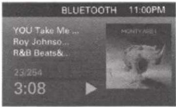
- After successfully pairing, connect the mobile device to the AWMC3 via Bluetooth. A Bluetooth logo will appear on the phone menu screen and show "CONNECT" "BT MUSIC" on the device LCD display.
- If the mobile device is "A2DP" format compatible, music playback can be controlled with the mobile device.
Play / Pause
Press Play / Pause Button (▶II) to play music. Press Play / Pause Button (▶II) to pause, and press again to continue playback.
Skip Track
Press the Previous / Next Buttons ( « / » ) to play the previous / next song stored in mobile device.
Apple Control
If an approved Apple ® device, iPhone ® 5S and up, is connected through Bluetooth, the Menu Button will allow selection of the music / artist / playlists on the phone. Rotating the VOL knob will adjust the highlighted selection. pressing the VOL knob will confirm the selection.
USB Mode
When a USB memory stick or approved Apple ® device is connected through USB, it will automatically change source and start playing the audio on the device. Pressing the Menu Button will allow control of the file browser on the USB memory stick or approved Apple ® device. When using a USB memory stick, press the Menu Button a second time to access a full directory. Album art will display if included in the file. Repeat and Shuffle functions are also selectable by pressing the Menu Button.
SPECIFICATIONS
Tuner FM
| Frequency Range | 87.5 - 107.9 MHz (America) |
| 87.5 - 108 MHz (Europe) | |
| Channel Step | 200 kHz (America) |
| 50 kHz (Europe) | |
| Sensitivity | 2.8 μV |
| Stereo Separation | 30dB |
| Signal to Noise Ratio | 50dB |
Tuner AM
| Frequency Range | 530 - 1710 KHz (America) |
| 522 - 1620 KHz (Europe) | |
| Usable Sensitivity | 32dB |
Tuner WB
| Frequency Range | 162.4 - 162.55 MHz |
Line-Out
| Output | 2V |
| Impedance | 10k Ohm |
General
| Power Supply | 12V DC (10.8-15.6V allowable) |
| Speaker Impedance | 2 - 8 ohm |
| Output Power | 50W x 4CH |
| Fuse | 20A |
Note: Specification and the design are subject to possible modification without notice due to improvements.
This equipment has been tested and found to comply with the limits for a Class B digital device, pursuant to Part 15 of the FCC rules. These limits are designed to provide reasonable protection against harmful interference in a residential installation. This equipment generates, uses, and can radiate radio frequency energy and, if not installed and used in accordance with the instructions, may cause harmful interference to radio communications. However, this is no guarantee that interference will not occur in a particular installation. If this equipment does cause harmful interference to radio or television reception, which can be determined by turning the equipment off and on, you are encouraged to try to correct the interference by one or more of the following measures:
- Reorient or relocate the receiving antenna.
- Increase the separation between the equipment and receiver.
- Connect the equipment to an outlet on a different circuit than the one to which the receiver is connected.
- Consult the dealer or an experienced radio/TV technician for help.
Changes or modifications not expressly approved by Mitek Corporation could void the user's authority to operate this equipment. This device complies with part 15 of the FCC Rules. Operation is subject to the following two conditions: (1) This device may not cause harmful interference, and (2) this device must accept any interference received, including interference that may cause undesired operation
© 2017 Mitek Corporation. All rights reserved. MTX is a trademark of Mitek Corporation. Designed and Engineered in the U.S.A. Sirius, XM and all related marks and logos are trademarks of Sirius XM Radio, Inc. All rights reserved. All other trademarks cited herein are the property of their respective owners.
Due to continual product development, all specifications are subject to change without notice.
MTX Audio, 4545 East Baseline Rd. Phoenix, AZ 85042 U.S.A. 1-800-225-5689
OWNER'S MANUAL
RZRPOD65
POLARIS® RZR® DASH SPEAKERS
IMPORTANT NOTICE
If you have any questions regarding wire routing in a vehicle, please contact MTX Technical Support at 1-800-225-5689.
When connecting power and ground wires ensure that the red power wire is fused at the point where it is connected to the vehicle's battery. Failure to do so can result in damage to the vehicle if a short circuit develops between the vehicle connection point and the product.
PRODUCT INFORMATION
| Model # |
| Serial # |
| Dealer's Name |
| Date of Purchase |
IN THE BOX
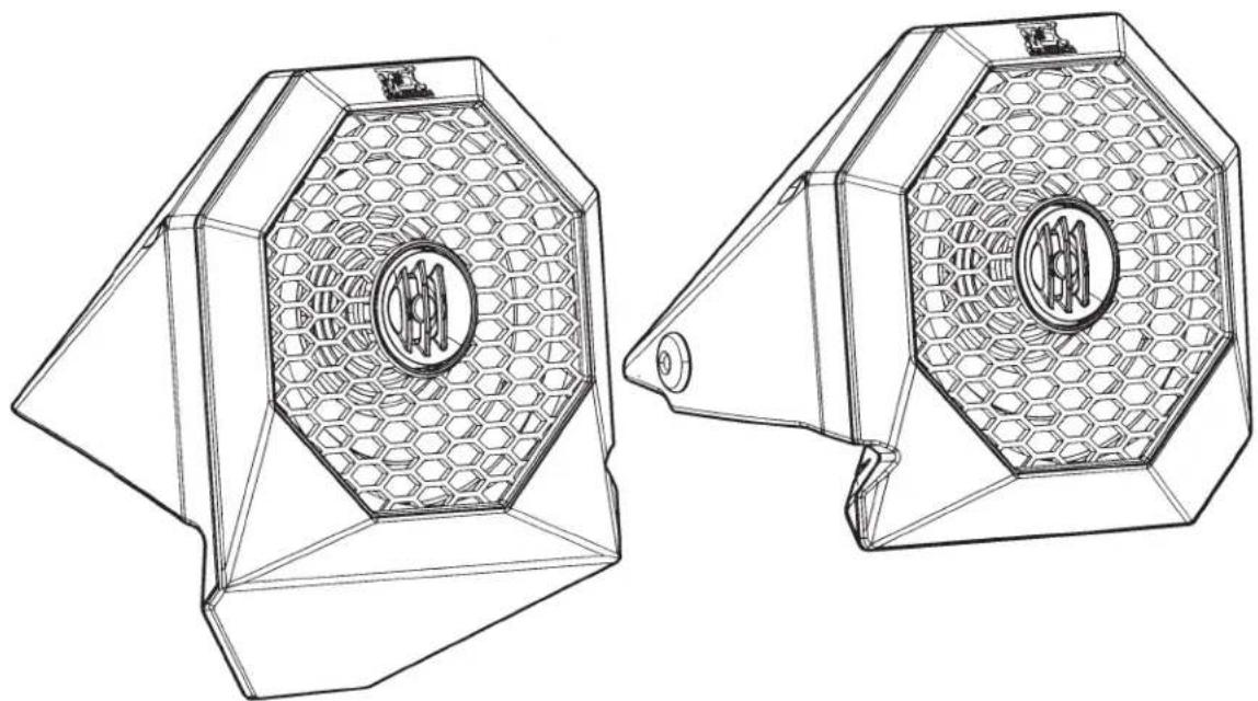
• Dash Speakers (Left and Right Enclosures)
• 15" (38.1cm) of Speaker Wire Extending from Each Enclosure
• (2) Brackets, Left and Right
• (4) M4-0.7 x 10mm Screw
• (6) pcs 3M Double Sided Tape
• (4) M4 Washers
ADDITIONAL ACCESSORIES NEEDED AND NOT INCLUDED
• 14-16 AWG Speaker Wire for Connection to Amplifier
INSTALLATION TOOLS
The following is a list of suggested tools needed for installation:
- Torx - T40
• 15mm Wrench or Socket
INTRODUCTION
Thank you for purchasing the MTX Audio 6" 2-way coaxial weatherproof dash speakers designed for the Polaris® RZR®. These easy to install dash speakers are the perfect OEM fit solution for your Polaris® RZR®. Congratulations and enjoy the ultimate audio experience with MTX!
FITS THE FOLLOWING VEHICLES
• RZR® XP / XP4 1000 (2014 and Up)
• RZR® XP / XP4 TURBO (2016 and Up)
• RZR® 900 / 900S / 1000S (2015 and Up)
• RZR® 4 900 EPS (2015 and Up)
FEATURES
• All Weather Construction with UV Inhibitor
- Custom Fit for RZR® Dashboard
• No Cutting or Drilling Required
- Won't Interfere with Aftermarket Cage
SPECIFICATIONS
• RMS Power Handling: 65-Watts
• Peak Power Handling: 130-Watts
• Sensitivity (2.83V/1m): 95dB
• Sensitivity (1W/1m): 90.7dB
• Frequency Response: 85Hz - 22kHz
- Impedance: 4Ω
INSTALLATION
Step 1 - Release the two quick locks to remove the hood from the vehicle.

Step 2 - Lift up the hood and slide towards the front of the vehicle.
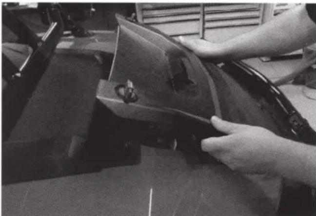
Step 3 - Remove the two (2) T40 screws holding down the top dash cover.
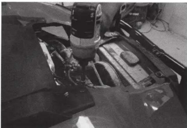
Step 4 - Lift and pull back the top dash cover to release the clips holding it in place. Unplug the gauge and switches making sure not to damage the vehicle and ignition wiring. Make note to remember what connector is associated with each specific switch.


Step 5 - Wipe the bottom surface of enclosure with isopropyl alcohol. Adhere the double sided 3M tape strips to the bottom of enclosure per locations shown in the picture. Do not remove the backing yet.

Step 6 - Place the left and right pods in their perspective locations. Wiring will be orientated toward the center of the machine. The left pod is slightly larger than the right pod. Run the wire through the small opening between the body panel and the roll cage. Make sure to not pinch or damage the wire. The wire can be reached from the inside of the body panel through the dash cover opening.

Step 7 - Connect the wires to your amplifier ensuring correct polarity positive-to-positive (+/+) and negative-to-negative (-/-). The wires included use a male and female bullet connector for a quick and solid connection. Use corresponding bullet connectors for the best connection. Test to make sure the amplifier connections are solid before bolting the enclosures on to the vehicle.
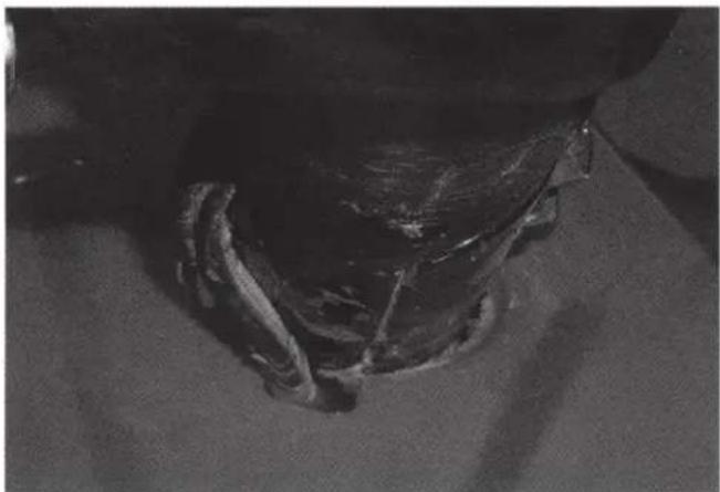
Step 8 - Remove the 15mm bolts from the roll cage on both right and left front roll cage junctions. Take the RZRPOD65 and the bracket and align the bracket mounting holes to the roll cage junction. The 15mm bolts that were removed will hold the bracket tight to the roll cage. The enclosures will sit within the front corners of the dash.
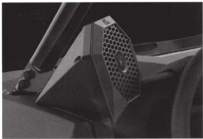
Step 9 - Securely attach the brackets to the enclosure using the provided M4 Screws. Using isopropyl alcohol, wipe any areas of the dash surface that will make contact with the speaker enclosures. Remove the tape backing. Align the bracket holes with the holes in the roll cage and press the enclosure into place. Replace the 15mm bolts in the roll cage, making sure to place the provided M4 washers between the mounting bracket and roll cage. Tighten the 15mm bolts into the roll cage per the manufacturer specified torque (Torque spec 40 ft-lbs.).

Step 10 - Replace all the parts and screws that have been removed and return the vehicle to its original assembled condition.

© 2016 Mitek Corporation. All rights reserved. MTX is a trademark of Mitek Corporation. All other trademarks are property of their respective owners. Designed and Engineered in the U.S.A.
Due to continual product development, all specifications are subject to change without notice.
MTX Audio, 4545 East Baseline Rd. Phoenix, AZ 85042 U.S.A. 1-800-225-5689
MTX005481 RevB 6/16 • 21A10519 • AW0015329
- IMPORTANT NOTICE
- PRODUCT INFORMATION
- IN THE BOX
- INSTALLATION TOOLS
- INTRODUCTION
- FITS THE FOLLOWING VEHICLES
- SPECIFICATIONS
- INSTALLATION
- FEATURES
- MOUNTING (USING MOUNTING PLATE)
- MOUNTING (USING U SHAPE BRACKET)
- MOUNTING (USING OPTIONAL VEHICLE SPECIFIC DASH MOUNT KIT - SOLD SEPARATELY)
- CONTROLS
- GENERAL OPERATIONS
- SWITCHING ON AND OFF
- OPERATING MODE
- VOLUME
- SOUND SETTINGS
- MUTE
- GENERAL SETTING
- RADIO FUNCTIONS
- SELECTING RADIO BAND
- AUTOMATIC OR MANUAL SEARCH FREQUENCIES
- STORING FREQUENCIES (6 PRESETS PER FM/AM BAND)
- RECALLING FREQUENCIES
- LOCAL
- SELECT USA / EUROPE AREA FREQUENCIES
- SIRIUSXM® OPERATION
- SELECTING SIRIUSXM
- MANUAL CHANNEL SELECTION
- RAPID CHANNEL BROWSING
- DIRECT TUNING
- CATEGORY LIST
- BAND OF PRESETS SELECTION
- USER RESET
- ADD PRESET CHANNEL
- RECALL PRESET CHANNEL
- PARENTAL CONTROL
- TEMPORARY UNLOCK
- TO CHANGE THE CODE
- TROUBLESHOOTING (CONT)
- BLUETOOTH AUDIO STREAMING
- PLAY / PAUSE
- SKIP TRACK
- APPLE CONTROL
- USB MODE
- ADDITIONAL ACCESSORIES NEEDED AND NOT INCLUDED
Brand : MTX Audio
Model : Thunder Sports MUDRZRDK
Category : Audio