
MBTA8250D - Subwoofer Bazooka - Free user manual and instructions
Find the device manual for free MBTA8250D Bazooka in PDF.


| Product Type | Subwoofer |
| Brand | Bazooka |
| Model | MBTA8250D |
| Speaker Size | 8 inches |
| Impedance | 4 ohms |
| Power Handling (RMS) | 250 watts |
| Peak Power Handling | 500 watts |
| Frequency Response | 30 Hz - 200 Hz |
| Sensitivity | 90 dB |
| Enclosure Type | Bass tube |
| Amplifier | Not included (passive subwoofer) |
| Mounting Depth | 5.5 inches |
| Overall Dimensions (Diameter x Length) | 10.5 x 18 inches |
| Weight | 15 lbs |
| Connector Type | Spring-loaded terminals |
| Color | Black carpet |
| Material | MDF and carpet |
| Recommended Enclosure Volume | 1.0 cubic feet |
| Maintenance | Wipe with dry cloth; avoid moisture |
| Safety | Keep away from heat sources; secure during transport |
| Spare Parts / Repairability | Contact Bazooka support for parts |
Frequently Asked Questions - MBTA8250D Bazooka
User questions about MBTA8250D Bazooka
0 question about this device. Answer the ones you know or ask your own.
Ask a new question about this device
Download the instructions for your Subwoofer in PDF format for free! Find your manual MBTA8250D - Bazooka and take your electronic device back in hand. On this page are published all the documents necessary for the use of your device. MBTA8250D by Bazooka.
USER MANUAL MBTA8250D Bazooka
natural_image
Technical line drawing of a mechanical component with multiple circular parts and internal features (no text or symbols)Installation Manual
Dear Friend,
Thank you for selecting Bazooka® subwoofer speaker systems for your stereo system. Today, the Bazooka represents Bazooka Mobile Audio's continued commitment to efficiency and design. An innovative manufacturing process developed by SAS® for the Bazooka provides consumers with state-of-the-art speaker system design.
At SAS, we take pride in manufacturing the most revolutionary bass speaker systems ever created, featuring our patented Bass Tubes ^® enclosure design, and we hope you will take pride in owning them.
Several years ago, we realized that efficiency was the wave of the future in Autosound, so we made a commitment to design, manufacture, and deliver the most efficient speaker systems possible.
Today we market our patented speaker systems worldwide and the high quality of the Bazooka brand is well respected by consumers and dealers of all nationalities.
When properly installed, Bazooka subwoofer speaker systems will give you years of clean uninterrupted sound reproduction. Therefore, I urge you to take a few minutes of your time to review this instruction booklet. It was designed to give you a better understanding of our products and to explain how to apply them properly.
Thank you again for choosing Bazookas. Our early commitment to quality has made them the product of choice, and I am sure you will agree that you have made the right one! Enjoy!

JON C. JORDAN
President
SAS/BAZOOKA
CONTENTS
HELPFUL HINTS BEFORE YOU BEGIN PG 4
VEHICLE PLACEMENT RECOMMENDATIONS PG 5-6
MOUNTING THE BAZOOKA PG 7-9
WIRING DIAGRAMS PG 10-11
SPECIFICATIONS PG 12&15
FEATURES PG 13-14
WIRING PG 16-20
TROUBLESHOOTING PG 21-22
WARRANTY PG 24-25
HELPFUL HINTS—BEFORE YOU BEGIN
Please take time to read through this manual and plan out your installation before you begin!
Locate an area in the rear of the vehicle where you would like to place the Bazooka speaker systems. The location you have selected must meet the following requirements in order for the Bazooka to be properly installed in the vehicle:
1) The woofer (grill end) should be facing into a corner. (See vehicle placement recommendations on pg. 5-6)
2) Ideally, there should be 2 to 4 inches between the woofer and the corner it is pointing into.
3) The mounting area should be carefully checked to be sure that the mounting screws will not damage the gas tank, electrical wiring, fuel lines, or the spare tire during the mounting of the strap bases.
4) The strap mounting bases should be screwed securely to a rigid surface that is part of, or anchored to, the structure of the vehicle.
VEHICLE PLACEMENT RECOMMENDATIONS
TRUCK INSTALLATION
tube size is exaggerated for emphasis

natural_image
Top-down technical line drawing of a car interior showing structural components and exhaust flow (no text or symbols)HATCHBACK INSTALLATION
tube size is exaggerated for emphasis

natural_image
Top-down line drawing of a car showing front, rear, side, and top views (no text or symbols)SEDAN INSTALLATION
tube size is exaggerated for emphasis

natural_image
Top-down line drawing of a car showing internal structural components (no text or symbols)BOAT PLACEMENT RECOMMENDATIONS
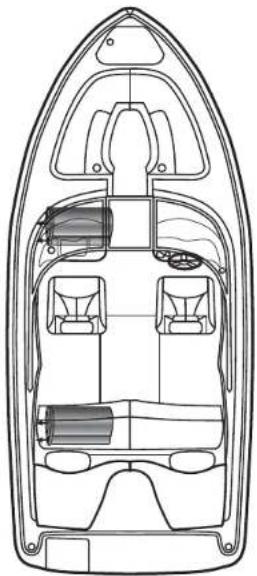
natural_image
Top-down line drawing of a boat interior layout with seating and compartments (no text or labels)BOW RIDER/SKI BOAT
tube size is exaggerated for emphasis
• Under passenger console
• Under seat storage compartment

natural_image
Top-down schematic of a boat interior layout showing seating, compartments, and structural elements (no text or labels)SPORT YACHT
tube size is exaggerated for emphasis
• Under bed storage compartment
• Under seat storage compartment
MOUNTING THE BAZOOKA
Figure 1
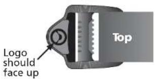
- With the topside of the buckle facing up (see figure 1), lace the strap through the mounting base as illustrated in figure 2

flowchart
graph LR
    A["Block 1"] --> B["Block 2"]
    B --> C["Flow Direction"]
    C --> D["Arrow Up"]
    C --> E["Arrow Down"]
    D --> F["Loop Back"]
    E --> F
    style A fill:#f9f,stroke:#333
    style B fill:#f9f,stroke:#333
    style C fill:#f9f,stroke:#333
    style D fill:#f9f,stroke:#333
    style E fill:#f9f,stroke:#333
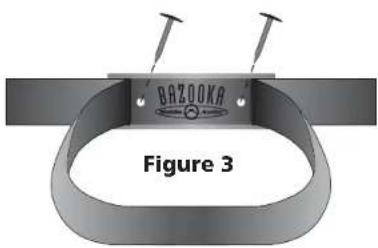
- After the strap is completely laced through the mounting base, make a loop with the strap, where it runs across the middle of the base as illustrated in figure 3. This loop is necessary to access the two mounting holes in the base.

natural_image
Diagram of a film reel with a central leaf and directional arrow, no text or symbols presentFigure 4
- Place each mounting base under the Bass Tubes ^® enclosure so that the apex at the bottom of the tube sits inside the mounting base as in figure 4.

- Move the bases so that they are spaced approximately 3" from each end of the enclosure as illustrated in figure 5.
- Remove the Bass Tubes® enclosure without moving the mounting bases and set it aside.
- Screw each mounting base securely in place with screws provided as illustrated in figure 3.

- Remove any slack in the strap by feeding it out of the mounting base on the loose end of the strap opposite the buckle.
- Place the Bass Tubes® enclosure on the mounting bases and fasten the buckles as illustrated in figure 7. The strap should loop through the buckle and be tightened securely by holding the strap in place with one hand and pulling the loose end away from the buckle, but against the cabinet.

Technical Note:
Due to the jarring and shifting that can occur in a vehicle, the mounting straps may stretch or loosen. We recommend that you check the straps regularly to assure that your Bass Tubes® enclosure is mounted securely in place.
A100 WIRING DIAGRAM

NOTE:
REMOVE AUTO TURN-ON LOOP TO USE ORANGEREMOTE WIRE FOR NORMAL REMOTE TURN-ON
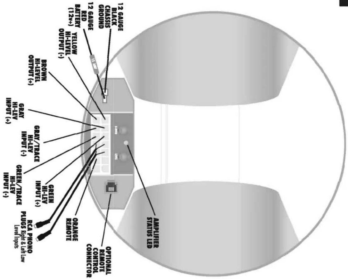
A200 WIRING DIAGRAM
AMPLIFIED TUBE SPECIFICATIONS
| BTA6100 | BTA8100 | BTA10100 | BTA6200 | BTA8200 | BTA10200 | CS8A5 | |
| Wooler Size | 6.5" | 8" | 10" | 6.5" | 8" | 10" | 8" |
| Voice Coil Size | 1.5" high power./high temp. | 1.5" high power./high temp. | 1.5" high power./high temp. | 1.5" high power./high temp. | 1.5" high power./high temp. | 1.5" high power./high temp. | 1" high power./high temp. |
| Magnet Size | 13 oz. | 15 oz. | 28 oz. | 20 oz. | 28 oz. | 28 oz. | 28 oz. |
| Frequency response* | 39-85 lcz. | 39-85 lcz. | 39-85 lcz. | 39-250 lcz. | 39-250 lcz. | 39-250 lcz. | sub 20-100lcz/Hi-pass 106-20khz |
| Efficiency** | 103 dB* | 105 dB* | 107 dB* | 100 dB* | 102 dB* | 104 dB* | 105 dB* |
| Power Handling | 100 watts | 100 watts | 100 watts | 200 watts | 200 watts | 200 watts | sub 100w x 1/hi-pass 25w x 4 |
| Dimensions | 18.125" x 6.75" x 8" | 18.125" x 8.5" x 10" | 20.875" x 10.3" x 12.2" | 18.325" x 6.75" x 8" | 18.325" x 8.5" x 10" | 21.7" x 10.3" x 12.2" | 18.325" x 8.5" x 10" |
| Weight | 12 lbs. | 14 lbs. | 24 lbs. | 15 lbs. | 20 lbs. | 25 lbs. | 20 lbs. |
| Impedance | 2 ohms DVC | 2 ohms DVC | 2 ohms DVC | 4 ohms | 4 ohms | 4 ohms | 2 ohms DVC |
PASSIVE TUBE SPECIFICATIONS
| BT6014/6018 | BT8014/8018 | BT1014/1018 | BT6024DVC/6028DVC | BT8024DVC/8028DVC | BT1024DVC/1028DVC | BT1214 | BT1224DVC | |
| Wooler Size | 6.5" | 8" | 10" | 6.5" | 8" | 10" | 12" | 12" |
| Voice Coil Size | 1.5" high power./high temp. | 2" high power./high temp. | 2" high power./high temp. | 1.5" high power./high temp. | 2" high power./high temp. | 2" high power./high temp. | 2" high power./high temp. | 2" high power./high temp. |
| Magnet Size | 20 oz. | 28 oz. | 28 oz. | 28 oz. | 36 oz. | 36 oz. | 36 oz. | 36 oz. |
| Frequency response* | 39-1500 hz. | 39-1500 hz. | 39-1000 hz. | 39-1500 hz. | 39-1500 hz. | 39-1000 hz. | 30-1000 hz. | 30-1000 hz. |
| Efficiency** | 100 dB* | 102 dB* | 104 dB* | 100 dB* | 102 dB* | 104 dB* | 106dB* | 106dB* |
| Power Handling | 6-100 watts/channel | 6-150 watts/channel | 6-200 watts/channel | 6-150 watts/channel | 6-200 watts/channel | 6-250 watts/channel | 6-250 watts/channel | 6-300 watts/channel |
| Dimensions | 18" x 6.75" x 8" | 18" x 8.5" x 10" | 20.75" x 10.3" x 12.2" | 18" x 6.75" x 8" | 18" x 8.5" x 10" | 20.75" x 10.3" x 12.2" | 22.5" x12.1" x14.4" | 22.5" x12.1" x14.4" |
| Weight | 11 lbs. | 15.5 lbs. | 23 lbs. | 13 lbs. | 19 lbs. | 26 lbs. | 28lbs. | 30lbs. |
| Impedance | 4 ohms/8 ohms | 4 ohms/8 ohms | 4 ohms/8 ohms | 4 ohms/8 ohms | 4 ohms/8 ohms | 4 ohms/8 ohms | 4 ohms | 4 ohms |
| MODEL FEATURES | ||||||
| BT6014/6018 | BT8014/6018 | BT1014/1018 | BT1214 | BTA6100 | BTA8100 | |
| Feature | ||||||
| Patented Bass Tube® enclosure design | X | X | X | X | X | X |
| Optimized for corner loading | X | X | X | X | X | X |
| Whiter resistant endstore | X | X | X | X | X | X |
| Fks in all vehicles | X | X | X | X | X | X |
| Upgrades every 12 well sound system | X | X | X | X | X | X |
| Perfect for leased vehicles | X | X | X | X | X | X |
| Hams audio quality sound | X | X | X | X | X | X |
| New and improved cosmetics | X | X | X | X | X | X |
| Dual voice coil inputs | ||||||
| Large oversized edge roll | ||||||
| Overseed torque and motor structure | ||||||
| Built-in 100 well mono amplifier | X | X | ||||
| Built-in 200 well motor mono amplifier | ||||||
| Nose reicking balanced input circuit | X | X | X | |||
| Fixed 85 h2 18 dB subwoofer crossover | X | X | X | |||
| Variable 60 - 250 Hz subwoofer crossover | ||||||
| Built-in 12/8 subsonic filter at 35 Hz | X | X | X | |||
| Optional remote level control | X | X | X | |||
| Optional remote crossover control | ||||||
| Optional Universal Mounting System | X | X | X | X | X | X |
| Jet black point finish | X | X | X | X | X | X |
| Platinum colored binding posts | X | X | X | X | ||
| One year warranty | X | X | X | X | X | X |
| Salt bag and LTI certified for 5 years | ||||||
| Whiterproof workers | ||||||
| Weather resistant vetro reinforced mounting straps | ||||||
| X | X | X | X | X | X | |||||||
| X | X | X | X | X | X | |||||||
| X | X | X | X | X | X | |||||||
| X | X | X | X | X | X | |||||||
| X | X | X | X | X | X | |||||||
| X | X | X | X | X | X | X | X | X | X | X | X | X |
| X | X | X | X | X | X | |||||||
| X | X | X | X | X | X | X | ||||||
| X | X | X | X | X | X | X | X | X | X | X | X | X |
| X | X | X | X | X | ||||||||
| X | X | X | X | X | X | X | ||||||
| X | X | X | X | X | X | X | ||||||
| X | X | X | X | X | X | X | ||||||
| X | X | X | X | X | ||||||||
| X | X | |||||||||||
| X | X | X | X | X | X | X | ||||||
| X | X | X | X | X | ||||||||
| X | X | |||||||||||
| X | X | X | X | |||||||||
| X | X | X | X | |||||||||
| X | X | X | X | |||||||||
| X | X | X | X | X | X | X | X | X | X | X | X | X |
| X | X | X | X | X | X | X | X | X | X | X | X | X |
| X | X | X | X | X | X | X | X | X | X | X | X | X |
| X | X | X | X | X | X | X | X | X | X | X | X | X |
| X | X | x | X | X | X | X | X | X | X | X | X | X |
| X | X | X | X | X | X | X | X | X | X | X | X | X |
| X | X | X | X | X | X | X | X | X | BTA8200 | BT1024DVC/102BDVC | ||
| MBTA10200 | MBTAB200 | MBTA10100 | MBTAB100 | MBT1014 | MBT8014 | MBT8014 | MBT10200 | MBT8014 | BTA6200 | BT1224DVC | ||
MARINE TUBE SPECIFICATIONS
| MBT8014MBT1014MBTA8100MBTA10100MBTA8200MBTA10200 | ||||||
| Woofer Size 8" 10" 8" 10" 8" 10" | ||||||
| Voice Coil Size | 1.5" high power./high temp. | 1.5" high power./high temp. | 1.5" high power/high temp | 1.5" high power./high temp. | 1.5" high power./high temp. | 1.5" high power./high temp. |
| Magnet Size | 28 oz. | 28 oz. | 15 oz. | 28 oz. | 28 oz. | 28 oz. |
| Frequency response* | 39-1500 hz. | 39-1000 hz. | 39-85 hz. | 39-85 hz. | 39-250 hz. | 39-250 hz. |
| Efficiency** | 102 dB* | 104 dB* | 105 dB* | 107 dB* | 102 dB* | 104 dB* |
| Power Handling | 6-150 watts/channel | 6-200 watts/channel | 100 watts | 100 watts | 200 watts | 200 watts |
| Dimensions | 18" x 8.5" x 10" | 20.75" x 10.3" x 12.2" | 18.125"x8.5"x10" | 20.875"x10.3"x12.2" | 18.325" x 8.5" x 10" | 21.1" x 10.3" x 12.2" |
| Weight | 15.5 lbs. | 23 lbs. | 14 lbs. | 24 lbs. | 20 lbs. | 25 lbs. |
| Impedance | 4 ohms | 4 ohms | 2 ohms DVC | 2 ohms DVC | 4 ohms | 4 ohms |
* The built in crossover limits the frequency response of the Amplified Bazooka.
** The efficiency levels of all Bazooka subwoofer speaker systems are measured in the typical environment: In the low bass region with one watt of power.
AMPLIFIED MODELS:
(BTA6100, BTA8100, BTA10100, BTA6200, BTA8200, BTA10100, MBTA8100, MBTA10100, MBTA8200, MBTA10200)
DO NOT substitute the fuse included with the Amplified Bazooka subwoofer with anything other than the SAME fast blow current rated fuse. Substitution or deletion will void the product's warranty and may cause damage to your car or the amplifier.
SHOULD I USE HIGH OR LOW LEVEL INPUTS?
If the source unit has only speaker outputs, use the high-level inputs of the Amplified Bazooka subwoofer. If the source unit has both high and low level outputs, we recommend using the high level inputs over the low level inputs, due to the configuration of the Amplified Bazooka subwoofer's balanced input circuit. Not all head units, even those that promise high output voltage in their marketing materials, indeed have high-voltage RCA outputs. Because of this, Bazooka Mobile Audio recommends using the speaker level inputs when in doubt—they will always provide sufficient drive level to the amplifier. PLEASE NOTE THAT THE WIRING IN A FACTORY STEREO MAY NOT BE ELECTRICALLY IN PHASE EVEN WHEN YOU HAVE MADE THE PROPER CONNECTIONS.
Take the time after you make your wire connections to run through the quick phase check procedure in the "AM I IN PHASE?" section at the end of this manual, and NEVER USE BOTH high and low-level inputs at the same time!
INPUT SIGNAL CONNECTIONS
High-Level Inputs:
If the source unit has both front and rear speaker outputs, use only one set of speaker outputs for the high-level input of the Amplified Bazooka. Connect the GREEN wire from the 14-pin Molex plug of the Amplified Bazooka subwoofer to the source units left (+) positive speaker output. Connect the GREEN W/BLACK stripe wire of the plug to the source units left (-) negative speaker output. Connect the GRAY wire of the plug to the source units right (+) positive speaker output. Connect the GRAY W/BLACK stripe wire of the plug to the source units right (-) negative speaker output. When using high-level inputs, take the time after you make all wiring connections to run through the AM I IN PHASE
procedure at the end of this manual to confirm that your inputs are in correct electrical phase and the proper bass response is being produced.
Low-Level Inputs:
If your source unit only has low-level RCA phono jack output, use only the low-level inputs of the Amplified Bazooka. Connect the low-level RCA phono jack inputs of the Amplified Bazooka subwoofer to the source with a shielded RCA patch cord. To avoid possible noise problems, be sure to run the patch cord away from all power wires and factory wire harnesses. When using the low-level inputs DO NOT make any connections to the Green and Gray high-level input wires of the Amplified Bazooka subwoofer and make sure these wires are insulated to avoid the possibility of a short circuit.
POWER WIRE (All Models)
The power wire must be fused and connected directly to the positive terminal of the battery to provide a power source with a low voltage drop and low noise. Do not make the power connection at the fuse block or any point other than the battery. Improper power sources can reduce output and cause distortion.
The fuse holder should be connected to the battery's positive terminal. The fuse is designed to prevent fire or damage to your car, should the battery wire short to ground. Wait to insert the fuse into its holder until all wire connections have been made.
If it is necessary to lengthen the battery wire, add the required length between the amplifier and the fuse holder, not the fuse holder and the battery. If you need to extend the battery wire, use 16 gauge or larger for all A100, and 12 gauge or larger for all A200 models. It is best to use as short a wire as possible. Be sure you DO NOT run the power wire next to the input cables of the amplifier this will induce noise. Avoid running the power wire near the radio's antenna or power leads, or near sensitive equipment or harnesses. The power wire carries substantial currents and could induce noise.
GROUND WIRE (All Models)
The ground wire must be connected directly to the vehicle chassis near the amplifier. We do not recommend extending the ground wire in any installation, as this can cause unwanted ground loops. The ground point in the car should be a piece of chassis metal that is part of or welded to the main body of the vehicle. Painted surfaces should be scraped or sanded clean to expose the bare metal before the ground lug is bolted down. (Cover the bare metal area with paint
or grease after you finish mounting the ground wire to prevent rust.)
REMOTE TURN ON OPTIONS
OPTION ONE:
When you are using this option with all amplified Bass Tubes ^® models: For the most versatility the Orange Remote Turn On Wire should be connected to the source unit's "Accessory", "Auto-Antenna" or "Remote" lead -- any of which will supply 12 Volts positive when the source is turned on.
OPTION TWO:
When you are using this option with all BTA100 AND MBTA100: If the source does not have an Auto-Antenna lead (or if the Auto-Antenna goes down during tape operation), you can connect the Amplified Bazookas' Remote Turn On Wire to an accessory or ignition point at the vehicle fuse block. In this configuration, the Amplified Bazooka subwoofer will be on whenever the ignition is on. This method may allow noise or turn-on-and-off transients to become amplified when the source unit is not in use, and therefore is a less desirable than option one. Locate the Auto/Off Jumper Loop located on the wiring harness; SAS ships the Amplified Bazooka subwoofer with this Jumper in the ON Position. The Quick Disconnect YELLOW On/Off Jumper Loop must be plugged into the harness.
The built-in crossover on the Amplified Bazooka subwoofer is an 18 dB per octave electronic low pass filter, it has a 60 Hz to 250 Hz variable crossover point. Select the crossover point that you feel best fits your system design. Set the potentiometer labeled XOVER to the point you selected, 60 Hz being all the way to the left (counterclockwise) and 250 Hz being all the way to the right (clockwise). When you have set the crossover, proceed to the next step.
PHASE SWITCH (All A100 MODELS ONLY)
When one of the High-level Input channels is out of phase electrically with the other High-level Input channel, your Amplified Bazooka subwoofer will sound as if it has little or no output and any output that is produced may sound distorted. If you suspect that your Amplified Bazooka subwoofer is out of phase, use the AM I IN PHASE procedure to diagnose and correct the Amplified Bazooka subwoofer output, and proper bass response will be produced.
To correct this situation, simply flip the phase switch on the Amplified Bazooka. When the input signal is in correct electrical phase, the level of bass output will be greatest when the balance control of the radio is set to the center position.
SETTING THE LEVEL (ALL A200 MODELS ONLY)
Locate the potentiometer labeled LEVEL. This is the level control. Start with the level control turned all the way to the left (counterclockwise). The bass should be off or very low at this point. Turn up your head unit until the sound from the existing speakers starts to clip or distort. This is the point in your system where you will get maximum volume with the least amount of distortion. With the head unit at this point, turn the level gain control up slowly until the bass volume blends well with the existing high frequency speakers. This should be the proper setting for the level gain control. Now that the level is set, you may want to go back to the x-over control and adjust the x-over point by ear to meet the desired sonic quality of your system design.
LED POWER INDICATOR
If power, ground and remote are connected properly, the LED light will illuminate.
WHITE = OFF
If you find you like to change the level of bass depending on what you are listening to and want an easy way to make this possible, you can purchase an optional Remote Level Control.
All A200 MODELS
Remote Bass Control and Crossover (RBCM-RS):
If you find you like to vary the crossover point in addition to changing the level of bass depending on what you are listening to and want an easy way to make this possible, you can purchase an optional Remote Level and Crossover Control.
These Remote Controls are accessories that are available from your Bazooka dealer or directly from Bazooka. Be sure to check out other optional accessories for your Bazooka at
PASSIVE MODELS
natural_image
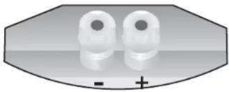
Two identical white circular objects with a plus sign below, enclosed in an octagonal frame (no text or symbols on the objects)(BT6014/6018, BT8014/8018, BT1014/1018, MBT8014, MBT1014 ONLY)
On the back of all Bazooka passive single voice coil models you will find a terminal cup with two 5-way platinum colored binding posts, red being positive and black being negative. Hook the positive speaker output from your amplifier to the red positive terminal of the Bazooka. Hook the negative speaker output from your amplifier to the black negative terminal. Repeat these steps for each Bazooka used.

natural_image
Diagram of four identical lightbulb-shaped components with plus and minus signs, no text or symbols present(BT6024DVC/6028DVC, BT8024DVC/8028DVC, BT1024DVC/1028DVC)
On the back of all Bazooka dual voice coil passive models you will find a terminal cup with four 5-way platinum colored binding posts, red being positive and black being negative. Hook the positive speaker output from your amplifier to the red positive terminal of the Bazooka. Hook the negative speaker output from your amplifier to the black negative terminal. Repeat these steps for each Bazooka used.
TROUBLESHOOTING
Am I In Phase?
If your inputs are out of phase and you turn the balance control of your radio all the way to one side, right or left, the bass output from the Bazooka® will increase. When you bring the balance control back to the center position the bass level will drop. This confirms that one of your input channels is wired out of phase with the other.
When one of the Amplified Bazooka's High-level Input channels is out of phase electrically with the other High-level Input channel, your Bazooka will sound as if it has little or no output and any output that is produced may sound distorted. If you suspect that your Bazooka is out of phase, use the AM I IN PHASE procedure to diagnose and correct the Bazookas' output, and proper bass response will be produced. channels is wired out of phase with the other. To correct this situation, simply flip the phase switch on the amplified Bazooka ^6 . When the input signal is in correct electrical phase, the level of bass output will be greatest when the balance control of the radio is set to the center position.
Do You Have A Phase Problem?
If the bass response in your application appears to be lower then you expected or sounds muffled and or distorted, you may be experiencing Phase Cancellation.
Phase Cancellation
When two speakers in the same frequency range produce sound waves that are inverted from one another or 180^ out of phase, the sound waves will cancel each other out to some degree. This effect will be heard as a drop in the output level and/or a muffled or muddy quality in the Bass Response. The source of this Phase Cancellation can be at any point in the signal path. The obvious cause of this problem would be a speaker connection that was reversed in polarity, but that is not always the case. Sometimes amplifier channels will shift phase 180^ for no good reason, or a signal processor could have a setting for phase that has been set incorrectly or the
source material could just be recorded in error. Also speaker placement and the acoustics of the listening environment can effect the phase. No matter what or where the cause is located, the solution is an easy one.
PHASE CORRECTING PROCEDURE
Disconnect all but one Bazooka ^® from your system. Be sure that any loose wire connections are insulated to avoid the chance of short-circuiting any of the electronic equipment. Listen to the system and take note of the level of the Bass Response. Connect the next Bazooka ^® and compare the level of the combined output to that of the single unit. If the Bass Response increases, the Phasing is correct and you can repeat this process on the next Bazooka. If the level of the Bass Response drops, the Phasing is incorrect and you should reverse the speaker connections to this Bazooka ^® and compare again. In short to INCREASE IS GOOD, to DECREASE IS BAD! Using this method, any number of Bazooka ^® subwoofers can be kept in absolute phase.
PRACTICE SAFE LISTENING
Continuous exposure to high volumes of sound may cause permanent hearing loss. High-powered auto sound systems are capable of producing sounds well over 130 dB. Even short periods of play at high volume levels can impair your ability to hear necessary traffic sounds and may constitute a hazard. Please use common sense and practice SAFE LISTENING!
LIMITED WARRANTY (UNITED STATES)
Southern Audio Services, Inc., warrants all products to be free from defects in material and workmanship for a period of one (1) year from the date of purchase.
In the event the product is not as warranted, SAS' sole obligation shall be to repair or replace the defective product at SAS' option: SAS limits its obligation under any implied warranties under state laws to a period not to exceed the limited warranty period. SAS and its authorized BAZOOKA® dealers specifically disclaim liability for any incidental or consequential damages. Some states to not allow limitations on how long an implied warranty lasts, and some states do not allow the exclusion or limitation of incidental or consequential damages, so the above limitation or exclusions may not apply to you. This warranty gives you specific legal rights, and you may have other rights, which vary from state to state.
What is covered:
This warranty covers all defects in materials or workmanship (parts and labor) in the product.
What is not covered:
This warranty does not cover the following:
- Damages occurring during shipment of the product to SAS for repair (claims must be presented to the carrier).
- Damages caused by accident, abuse, negligence, misuse or improper operation or installation.
- Damages caused by an act of God, including without limitation, fire, flood, storms, or other acts of nature.
- Any product, which has a serial number, defaced, altered, modified, or removed.
- Any product that has been altered or modified without SAS' consent.
How to obtain warranty services:
- You are responsible for delivery of the product to an authorized BAZ®OKA dealer or contact SAS at 1-800-THE TUBE for a Return Authorization number. The Return Authorization number must be clearly written on the outside of the box. Freight must be prepaid to SAS. Warranty replacement parts will be returned freight prepaid. The entire enclosure may be returned for warranty service, but return will be freight collect.
- You must provide proof of the date of purchase of the product. If proof of purchase is not provided, original date of manufacture will be used to determine warranty period.
- You must package the product securely to avoid damage during shipment.
- After acquiring a Return Authorization number, ship to the address below.
PLEASE RETURN THIS PORTION IMMEDIATELY
MODEL#
SERIAL#
PURCHASE DATE
DEALER PURCHASED FROM
DEALER ADDRESS
TELEPHONE
PURCHASERS NAME
STREET ADDRESS
CITY
STATE ZIP
TELEPHONE

natural_image
Three parallel horizontal black lines on white background (no text or symbols)
SOUTHERN AUDIO SERVICES, INC.
14763 FLORIDA BLVD.
BATON ROUGE, LA 70819
HERE
PLACE STAMP
- CONTENTS
- HELPFUL HINTS—BEFORE YOU BEGIN
- Please take time to read through this manual and plan out your installation before you begin!
- VEHICLE PLACEMENT RECOMMENDATIONS
- BOAT PLACEMENT RECOMMENDATIONS
- MOUNTING THE BAZOOKA
- Technical Note:
- NOTE:
- AMPLIFIED MODELS:
- (BTA6100, BTA8100, BTA10100, BTA6200, BTA8200, BTA10100, MBTA8100, MBTA10100, MBTA8200, MBTA10200)
- SHOULD I USE HIGH OR LOW LEVEL INPUTS?
- INPUT SIGNAL CONNECTIONS
- High-Level Inputs:
- Low-Level Inputs:
- POWER WIRE (All Models)
- GROUND WIRE (All Models)
- REMOTE TURN ON OPTIONS
- OPTION ONE:
- OPTION TWO:
- PHASE SWITCH (All A100 MODELS ONLY)
- SETTING THE LEVEL (ALL A200 MODELS ONLY)
- LED POWER INDICATOR
- All A200 MODELS
- Remote Bass Control and Crossover (RBCM-RS):
- PASSIVE MODELS
- (BT6014/6018, BT8014/8018, BT1014/1018, MBT8014, MBT1014 ONLY)
- (BT6024DVC/6028DVC, BT8024DVC/8028DVC, BT1024DVC/1028DVC)
- TROUBLESHOOTING
- Am I In Phase?
- Do You Have A Phase Problem?
- Phase Cancellation
- PHASE CORRECTING PROCEDURE
- PRACTICE SAFE LISTENING
- LIMITED WARRANTY (UNITED STATES)
- What is covered:
- What is not covered:
- How to obtain warranty services:
- PLEASE RETURN THIS PORTION IMMEDIATELY
Brand : Bazooka
Model : MBTA8250D
Category : Subwoofer