PD-6607 - Uncategorized Posiflex - Free user manual and instructions
Find the device manual for free PD-6607 Posiflex in PDF.


| Product Type | POS Terminal |
| Brand | Posiflex |
| Model | PD-6607 |
| Display Size | 15 inches (diagonal) |
| Touch Technology | Projected Capacitive Touch |
| Resolution | 1024 x 768 (XGA) |
| Processor | Intel Celeron J1900 (Quad-Core, 2.0 GHz) |
| RAM | 4 GB DDR3L (expandable to 8 GB) |
| Storage | 64 GB SSD |
| Operating System | Windows 10 IoT Enterprise |
| Dimensions (W x H x D) | 370 x 295 x 45 mm |
| Weight | 2.8 kg |
| Power Supply | 12V DC, 3A (external adapter) |
| Operating Temperature | 0°C to 40°C |
| Interfaces | 2 x USB 2.0, 2 x USB 3.0, 1 x RJ45 LAN, 2 x COM, 1 x VGA, 1 x HDMI |
| Brightness | 250 cd/m² |
| Touch Points | 10-point multi-touch |
| Fanless Design | Yes |
| Mounting | VESA 75 x 75 mm |
| IP Rating (front) | IP54 |
| Warranty | 2 years |
Frequently Asked Questions - PD-6607 Posiflex
User questions about PD-6607 Posiflex
0 question about this device. Answer the ones you know or ask your own.
Ask a new question about this device
Download the instructions for your Uncategorized in PDF format for free! Find your manual PD-6607 - Posiflex and take your electronic device back in hand. On this page are published all the documents necessary for the use of your device. PD-6607 by Posiflex.
USER MANUAL PD-6607 Posiflex
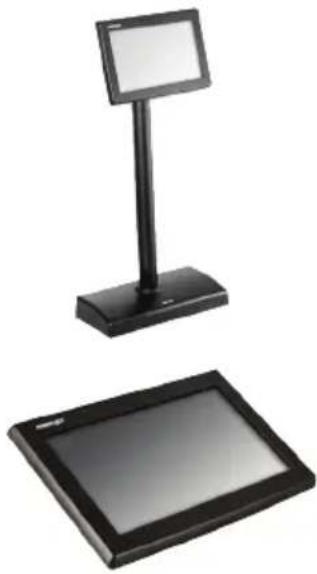
Customer Display User Manual
natural_image
Two black electronic display stand devices, one with a top screen and the other a flat screen (no text or symbols visible)Package Contents
√ 7" PD-6X07R/ PD-6X07R-AR/ PD-6X07U / PD-6X07U-AR customer display (x 1)
√ Stand base for PD-6207 series only (x 1)
√ RS-232 cable for PD-6X07R/ PD-6X07R-AR only (x 1)
√ USB cable for PD-6X07U/ PD-6X07U-AR only (x 1)
√ Mounting kits (x 1)
√ User manual (x 1)
√ Information CD (x 1)
Product Features
Among PD-6X07 series, PD-6X07R/ PD-6X07U are models which support multiple languages, including English, Traditional Chinese, Simplified Chinese and Japanese; PD-6X07R-AR/ PD-6X07U-AR are models with Arabic language support.
7" Graphical customer line display
▶ TFT LCD panel
20 x2, 20 x4, 30 x4 characters support
Adjustable font and background color
JPEG graphics display support
Command emulations support : ADM, Aedex, ESC/POS, Futaba, Noritake, UTC
Compatibility with Posiflex terminals
| Display Model | Posiflex POS model |
| PD-6207R/ PD-6207R-AR/PD-6207U/ PD-6207U-AR | Any Posiflex terminal |
| PD-6307R/ PD-6307R-AR/PD-6307U/ PD-6307U-AR | 15”/17” KS series terminals |
| PD-6507R/ PD-6507R-AR/PD-6507U/ PD-6507U-AR | HS series terminals |
| PD-6607R/ PD-6607R-AR/PD-6607U/ PD-6607U-AR | XT series terminals |
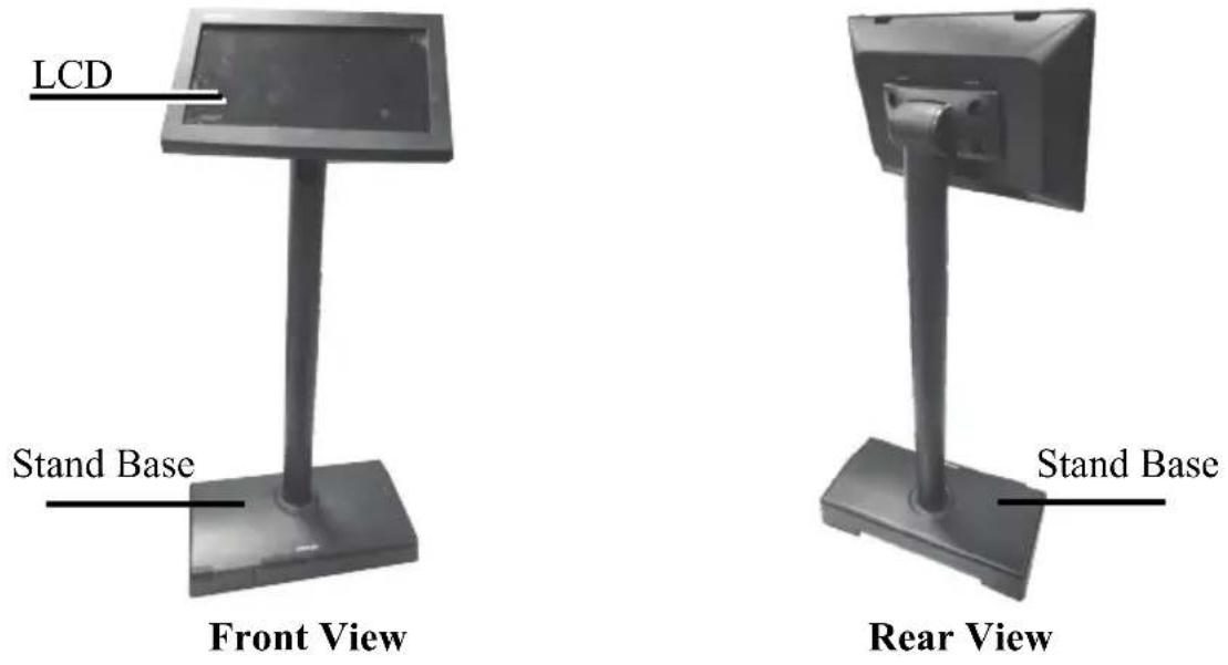
Views of the PD-6X07 Series
PD-6207 Series
PD-6307 Series
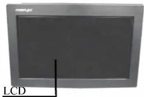
Front View
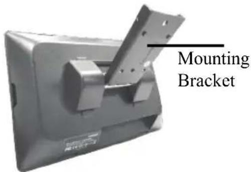
Rear View
PD-6507 Series
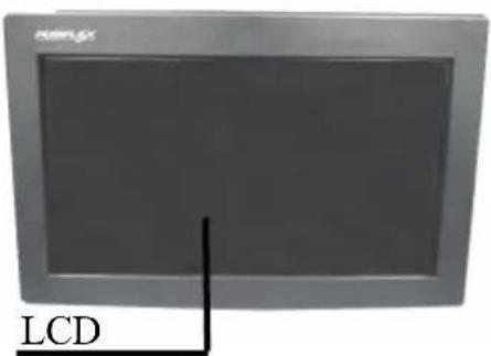
Front View
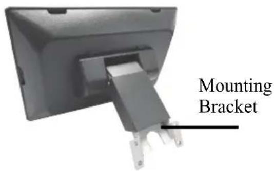
Rear View
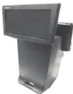
PD-6607 Series
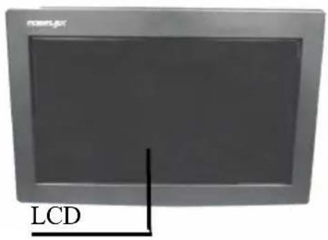
Front View
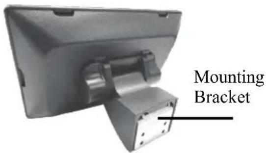
Rear View
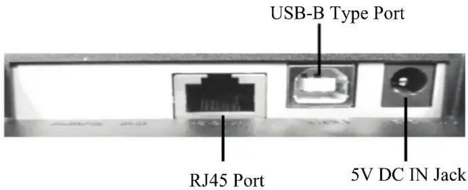
View of I/O Interface of PD-6X07R/ PD-6X07R-AR
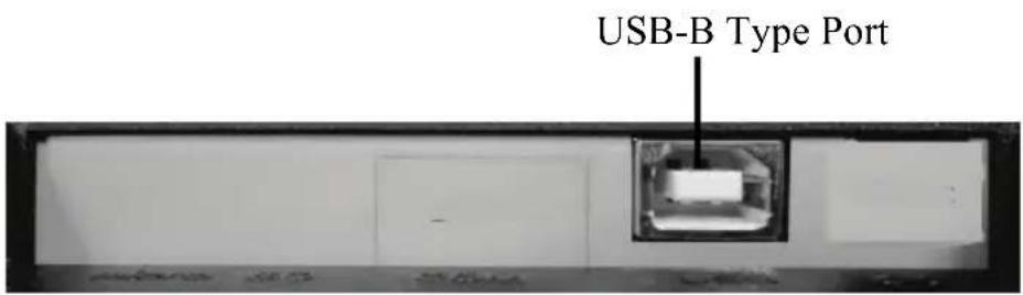
View of I/O Interface of PD-6X07U/ PD-6X07U-AR
Mounting PD-6207 Series onto POS Terminal
Please follow the below instructions to install PD-6207 series customer display onto your POS terminal. During installation, do NOT power ON the terminal. In the example, XT-3000 POS terminal will be used to demonstrate how to complete the installation.
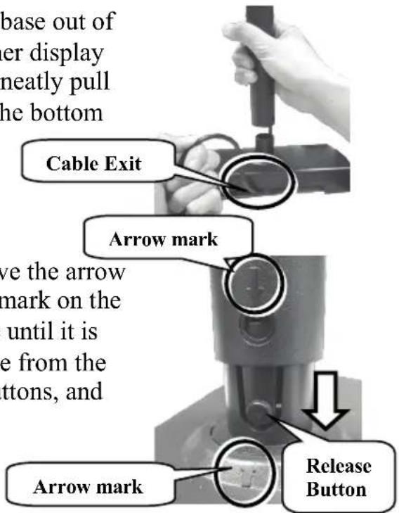
- Take the customer display and stand base out of the package. While lifting the customer display with one hand holding onto the tube, neatly pull the extra cable through cable exit at the bottom of the stand base.
-
To join the tube to the stand base, have the arrow of the tube point towards the similar mark on the stand base. Then, push down the tube until it is locked into place. (To release the tube from the stand base, hold down two release buttons, and then twist and pull up the tube.)
-
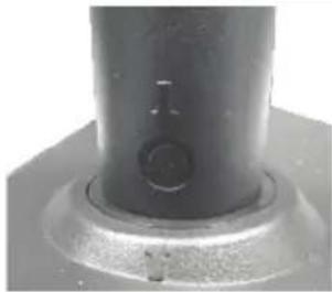
Make sure the tube is well inserted to the stand base.
natural_image
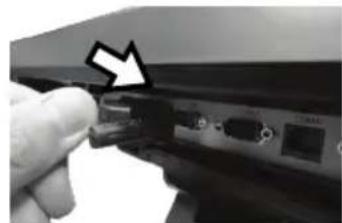
Close-up of a mechanical component with a cylindrical shaft and flange (no visible text or symbols)- Connect USB or RS-232 cable to the POS terminal. If you are the PD-6207R/ PD-6207R-AR user, take RS-232 converter cable and then attach DB9 connector to the DB9 COM port of your terminal. For PD-6207U/ PD-6207U-AR models, please insert USB Type-A connector of USB cable into USB port of your terminal.
natural_image
Close-up of a hand inserting a USB into a device panel with an arrow pointing to the component (no visible text or symbols)PD-6207R/PD-6207R-AR
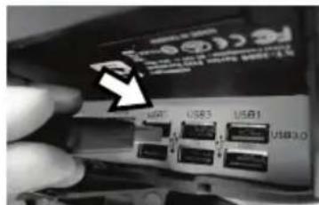
PD-6207U/PD-6207U-AR
- Make sure the other end of USB or RS-232 cable is well connected to the customer display.
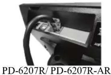
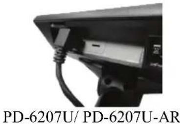
- The installation of PD-6207R/ PD-6207R-AR/PD-6207U/ PD-6207U-AR is completed.
natural_image
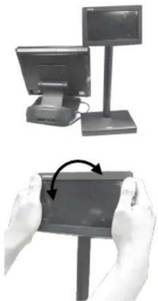
Two-panel image showing a desktop monitor and a tablet device being held, with hands performing a rotation (no text or symbols visible)- Tilt up and down the customer display in the direction shown by the arrow. Please do not press on the LCD panel while adjusting the titling angle.
Mounting PD-6307 Series onto 15"/17" KS series Terminal
The following section will give instructions on how to mount PD-6307 series customer display onto 15"/17" KS series POS terminal. During installation, do NOT power ON the terminal. In the example, KS-7515 POS terminal will be used to demonstrate how to complete the installation.
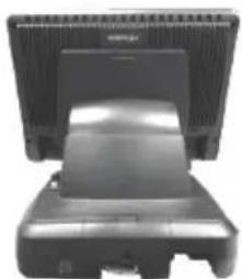
- Position your terminal with its rear facing towards you.
natural_image
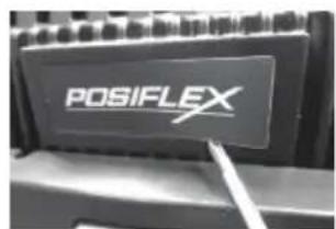
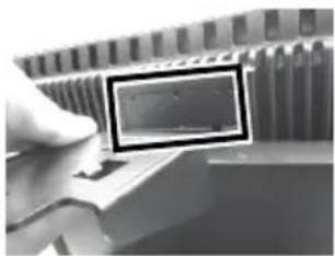
Front view of a computer monitor with a flat screen and a black cover (no visible text or symbols)- Locate the "Posiflex" sticker at the rear of the terminal. Use a pin tool to tear off the sticker which is used to cover the screw holes.
- Take L type mounting bracket out of the package. Align the four screw holes of the mounting bracket with the hole pattern at the back of the terminal.
- Insert four #6-32-12L fixing screws into the screw holes and then tighten the screws to secure the mounting bracket.
- Lay the customer display on a flat surface with its screen facing downwards.
- While holding the customer display steady with one hand, pull the monitor bracket upright.
- Lift the customer display to align three screw holes of its own bracket to those on the bracket attached to the terminal using the alignment dots.
natural_image
Close-up of a hand holding a small rectangular object with a dark border, next to a row of electronic components (no visible text or symbols)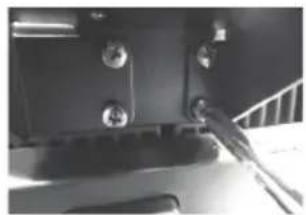
natural_image
Close-up of a mechanical component with bolts and a cable, no visible text or symbols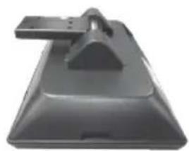
natural_image
Exterior view of a black plastic mechanical component with a triangular handle and rectangular base (no text or symbols visible)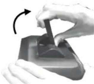
natural_image
Close-up of hands using a handheld device to press or adjust a component, with an arrow indicating rotation (no text or symbols visible)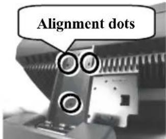
- Insert three #6-32-6L fixing screws into the screw holes, and then tighten them to well attach two brackets.
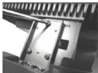
natural_image
Close-up of a mechanical assembly with metallic components and bolts (no visible text or symbols)- Make sure the customer display is well mounted onto your terminal. .
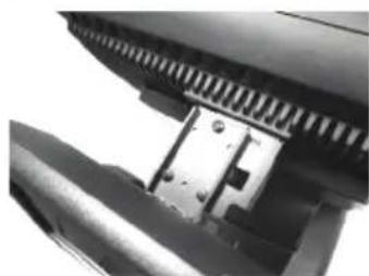
natural_image
Close-up of a mechanical component with textured surfaces and a metallic bracket (no visible text or symbols)- Connect USB or RS-232 cable to the POS terminal. If you are the PD-6307R/ PD-6307R-AR user, take the RS-232 cable to attach DB9 connector to the DB9 COM port in the bottom I/O compartment of your terminal. For the PD-6307U/ PD-6307U-AR models, insert the USB Type-A connector to the USB port of the terminal.
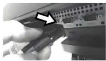
natural_image
Close-up of a hand holding a USB cable next to an electronic device (no visible text or symbols)PD-6307R/ PD-6307R-AR
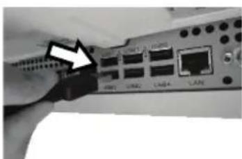
natural_image
Close-up of a network switch interface with labeled ports (no readable text or symbols)PD-6307U/ PD-6307U-AR
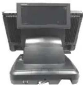
- Position the terminal with its rear facing towards you.
natural_image
Front view of a desktop computer with monitor and keyboard (no visible text or symbols)- Connect USB or RS-232 cable to the customer display.
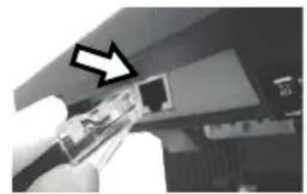
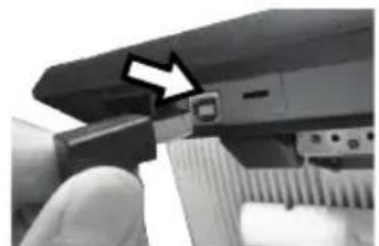
If you are the PD-6307R/ PD-6307R-AR user, plug the RJ-45 connector of RS-232 cable into the RJ-45 port of the customer display.
For PD-6307U/ PD-6307U-AR models, have the USB Type-B connector of USB cable attached to the USB port of your customer display.
natural_image
Close-up of a gloved hand holding a transparent plastic electronic component with an arrow pointing to it (no visible text or symbols)PD-6307R/ PD-6307R-AR
natural_image
Close-up of a computer monitor with an arrow pointing to the screen (no visible text or symbols)PD-6307U/ PD-6307U-AR
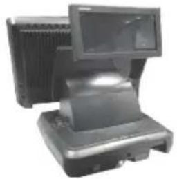
- The installation of PD-6307R/ PD-6307R-AR/PD-6307U/ PD-6307U-AR is completed.
natural_image
Exterior view of a desktop computer with monitor and keyboard (no visible text or symbols)- Tilt the customer display in the direction shown by the arrow in the figure. Please do not press on the LCD panel while adjusting the tilt angle.
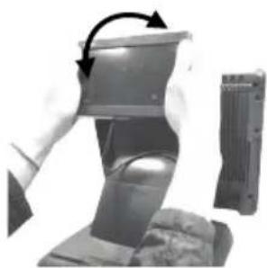
natural_image
Mechanical assembly showing a piston-like component being lifted by an arrow, with a separate side view of a cylindrical housing (no text or symbols visible)Mounting PD-6507 Series onto HS series Terminal
Please go through below instructions to install PD-6507 series customer display onto Posiflex HS series terminals. During installation, do NOT power ON the terminal. In the example, HS-2208E POS terminal will be used to demonstrate how to complete the installation.
- Lay your POS terminal on a flat surface with its rear facing towards you.
natural_image
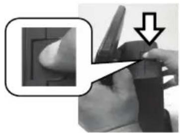
Exterior view of a modern office building (no signage)- Press down the release tab of top I/O interface cover.
natural_image
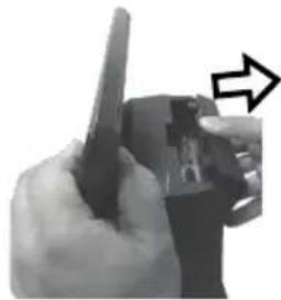
Close-up of a hand holding a small object with a downward arrow, no visible text or symbols- Pull the top I/O cover in the direction shown by the arrow in the figure to remove the cover.
natural_image
Close-up of a hand holding a pen, with an arrow pointing to the pen tip (no visible text or symbols)- Position the customer display on a flat surface. While keeping it steady with one hands, pull the rear mounting bracket upright as shown in the figure.
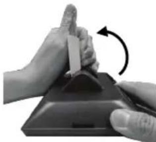
natural_image
Close-up of hands performing a finger manipulation on a device (no text or symbols visible)- Lift the customer display up to align the four screw holes of the mounting bracket with the holes in the top I/O interface compartment of your POS as shown in the figure.
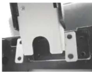
natural_image
Close-up of a mechanical component with a white bracket and mounting holes (no visible text or symbols)- Insert four #6-32-8L fixing screws into the screw holes and tighten them to secure the mounting bracket.
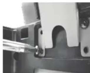
natural_image
Close-up of a mechanical component with a U-shaped cut and mounting holes (no visible text or symbols)- Make sure the customer display is well secured to the terminal.
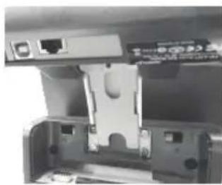
natural_image
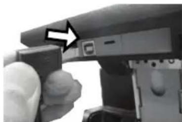
Close-up of a mechanical or electronic component with internal components and ports (no visible text or symbols)- Connect the USB or RS-232 cable to the customer display. If you are the PD-6507R/ PD-6507R-AR user, plug the RJ-45 connector of RS-232 cable with the label describing “To PD” into the RJ-45 port of your customer display. For PD-6507U/ PD-6507U-AR models, plug USB Type-B connector of USB cable into the USB port of the customer display.
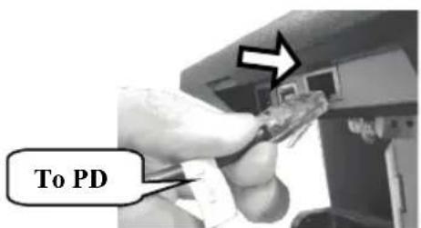
PD-6507R/ PD-6507R-AR
natural_image
Close-up of a hand holding a device with an arrow pointing to a button (no visible text or symbols)PD-6507U/ PD-6507U-AR
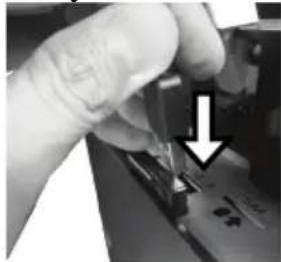
- Connect the USB or RS-232 cable to the POS terminal. If you are the PD-6507R/ PD-6507R-AR user, attach the RJ-50 connector of RS-232 cable with the label describing "To Host" to the RJ-50 COM port in the top I/O compartment of your terminal. For PD-6507U/ PD-6507U-AR models, plug USB Type-A connector of USB cable into the USB port of your terminal.
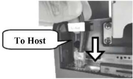
PD-6507R/ PD-6507R-AR
natural_image
Close-up of a hand inserting a small electronic component into a device (no visible text or symbols)PD-6507U/PD-6507U-AR
- Break the release tab of the top I/O interface cover.
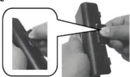
natural_image
Close-up of hands adjusting a black mechanical component with a close-up inset showing the detail (no text or symbols visible)- Align the two wedge tabs of the top I/O cover with two wedged portion of the top I/O compartment of the terminal.
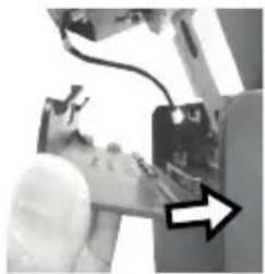
natural_image
Close-up of a hand holding an electronic device with a cable and a black arrow pointing to it (no visible text or symbols)- To keep the cable organized, tuck the extra cable into the I/O compartment and thread the cable through the cable exit as shown in the figure.
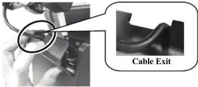
- Push the back cover into place.
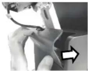
natural_image
Close-up of a hand holding a small metallic object with a curved line, next to a white arrow pointing right (no text or symbols visible)- The installation of PD-6507R/ PD-6507R-AR/PD-6507U/ PD-6507U-AR is completed.
natural_image
Exterior view of a modern office building (no signage)- Tilt the display up or down in the direction shown by the arrow. Please do not press on the LCD panel while setting up the tilting angle.
natural_image
Person in gloves holding a black plastic container with an arrow indicating rotation (no text or symbols visible)Mounting PD-6607 Series onto XT Series Terminal
The following steps are provided to guide you through the process of installing PD-6607 series customer display to XT series terminals with Gen 7E/8E base. During installation, do NOT power ON the terminal. In the following demonstration, XT-5415 POS terminal with Gen 7E base stand will be used to show how to complete the installation. You are able to apply similar cable-routing rules while dealing with XT series terminals with Gen 8E base.
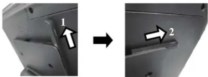
- Positon your terminal with its rear facing toward you. At the edges of the base stand bracket are located two shorter horizontal rails (2) (3) and two longer vertical rails (1) (4), which are used to hold your cable into place.
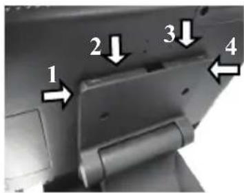
- Release the rail from the base.
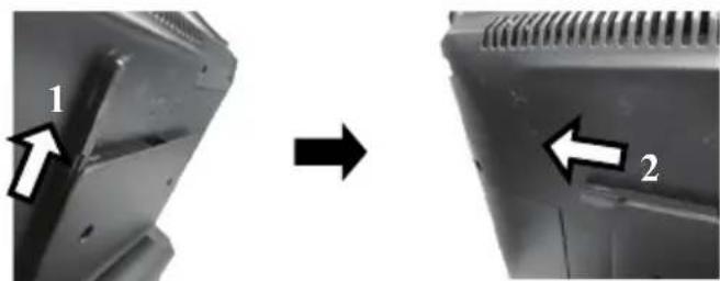
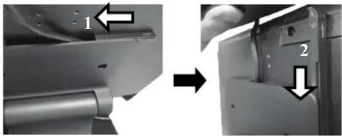
To run the cable through the cable passage on the left, according to the sequence number, first remove the longer rail and then the shorter one from the base stand by sliding them in the direction shown by the arrow
natural_image
Close-up of a mechanical component before and after transformation, showing two directional arrows (1 and 2) indicating movement or change.Or, if you prefer to thread the cable through the cable passage on the right side, first remove the longer rail and then shorter one from the base stand according to the sequence number.
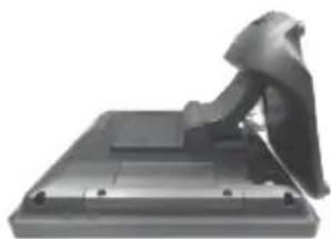
- Position your terminal with its screen facing downwards.
natural_image
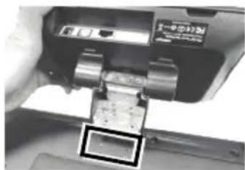
Exterior view of a modern office building (no signage)- Take the customer display out of the package box. Align the four fixing screw holes on its mounting bracket with the hole pattern at the rear of the terminal as shown in the figure.
natural_image
Close-up of a mechanical device with a highlighted component (no visible text or symbols)-
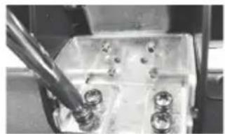
Insert four #6-32-10L screws into the screws holes and then tighten them to secure the mounting bracket.
-
Have your system sit upright with its rear facing toward you.
natural_image
Close-up of a mechanical component with a metal rod inserted, showing bolts and nuts (no visible text or symbols)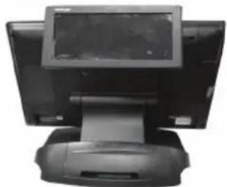
natural_image
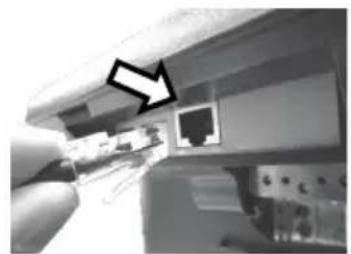
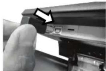
Front view of a desktop computer monitor with a screen and base (no visible text or symbols)- Connect USB or RS-232 cable to the customer display. If you are the PD-6607R/ PD-6607R-AR user, take RS-232 cable to plug the RJ-45 connector into the RJ-45 port of the customer display. For PD-6607U/ PD-6607U-AR models, please attach the USB Type-B connector of USB cable to the USB port of the customer display.
natural_image
Close-up of a hand inserting a USB into a device (no visible text or symbols)PD-6607R/ PD-6607R-AR
natural_image
Close-up of a hand pressing a button on a device (no visible text or symbols)PD-6607U/ PD-6607U-AR
- Tuck the extra cable into cable passages. Please also reserve the enough cable needed for tilting the customer display. In the example, the cable is routed through the cable passage on the right side.
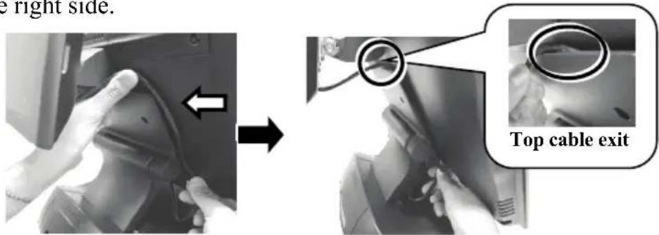
- Push the rails back to the base.
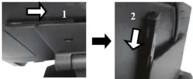
If the cable is threaded through the cable passage on the right, by following the sequence number, first slide the shorter rail horizontally and then longer one vertically into place in the direction shown by the arrow to fix your cable into place.
Alternatively, if you intend to lock the cable into the cable passage on the left, according to to the sequence number, first slide the shorter rail and then longer one into place in the direction shown by the arrow.
natural_image
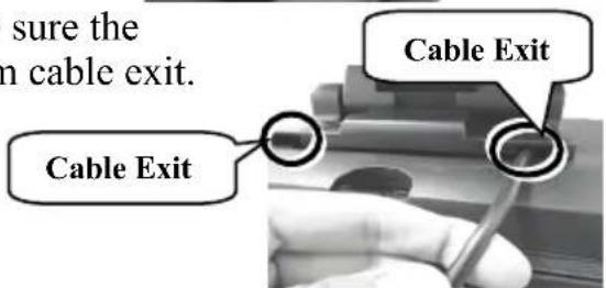
Two-step diagram showing a device before and after transformation, with arrows indicating direction (no text or symbols present)- After the rails are sild back, make sure the cable can be pull out of the bottom cable exit.
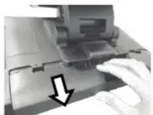
- Remove the cover for the bottom I/O compartment.
natural_image
Close-up of a hand pressing down on a mechanical device with a downward arrow indicating compression (no text or symbols visible)- Connect USB or RS-232 cable to the POS terminal.
If you are the PD-6607R/ PD-6607R-AR user, have DB9 connector of RS-232 cable attached to the DB9 COM port at the bottom I/O plate of your terminal.
For PD-6607U/ PD-6607U-AR models, connect the USB Type-A connector of USB cable to the USB port of your terminal.
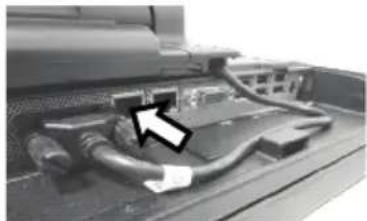
natural_image
Close-up of a computer monitor with cable and ventilation ducts (no visible text or symbols)PD-6607R/PD-6607R-AR
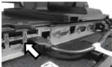
natural_image
Close-up of a mechanical or electronic component with visible connectors and cables (no text or symbols)PD-6607U/ PD-6607U-AR
-
After tucking the extra cable into the bottom I/O compartment, push back the cover to close the compartment.
-
The installation of PD-6607R/ PD-6607R-AR/PD-6607U/ PD-6607U-AR is completed.
-
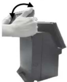
Tilt the customer display up and down in the direction shown by the arrow in the figure. While setting up the tilting angle, please be careful not to press on the LCD panel.
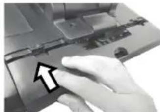
natural_image
Close-up of a hand pressing down on a laptop keyboard (no visible text or symbols)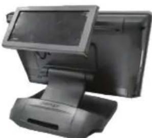
natural_image
Front view of a black electronic POS terminal with a screen and base (no visible text or symbols)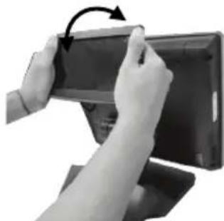
natural_image
Close-up of hands holding a tablet device with a curved arrow indicating rotation (no text or symbols visible)Activating Power to Serial Ports for PD-6X07R/PD-6X07R-AR via BIOS
To ensure PD-6X07R/ PD-6X07R-AR is able to extract power out of the RS-232 ports of the Posiflex terminals, it is significant to utilize BIOS to manually enable the power output to the serial port which the customer display is connected to before the PD-6X07R/ PD-6X07R-AR could start up. However, if the customer display you are using is not manufactured by Posiflex, it is strongly suggested to deactivate the power to RS-232 port of your terminal in preventing the customer display from being damaged.
Please go through the below instructions to activate the power output via BIOS settings for PD-6X07R/ PD-6X07R-AR. Also, the POS terminal has to be completely shut down before you intend to connect the cable into the serial port of the terminal.
- Make sure that PD-6X07R/ PD-6X07R-AR is well connected to the Posiflex terminals using the RS-232 cable.
- Press the power button of the POS to power on the terminal. During the boot process, hit F2 key to access BIOS setting.
- Use arrow keys to check the setting of the particular serial port used by PD-6X07R/ PD-6X07R-AR. If it is set to be disabled, hit Enter key to enable the serial port.
- Switch to Exit tab and select Exit Saving Changes option. Choose Yes in Setup Confirmation message box to save your configurations.
- After rebooting your POS, make sure PD-6X07R/ PD-6X07R-AR is successfully initiated.
Powering ON/OFF PD-6X07 Series
Instead of using an external power supply, PD-6X07 series customer displays primarily depend on Posiflex POS terminals as primary power sources. In such a case, the customer display will be automatically initiated when the terminal is powered up, and shut down immediately after you power the POS off.
For PD-6X07R/ PD-6X07R-AR models, please do first follow what is specified in the previous section, Activating Power to Serial Port for PD-6X07R/ PD-6X07R-AR via BIOS, to ensure that the power output to the customer display is actually activated.
Power ON the PD-6X07 Series
Press the power button of the POS terminal to power on your terminal. Few seconds later the customer display will be initiated.
Power OFF the PD-6X07 Series
After you follow the standard shutdown procedure to power off the POS terminal, the customer display will be turned off accordingly.
Installing the Virtual COM Driver for PD-6X07U/PD-6X07U-AR only
Refer to the following steps to install the driver for PD-6X07U/PD-6X07U-AR models.
-
Connect the USB cable of PD-6X07U/ PD-6X07U-AR to your POS terminal.
-
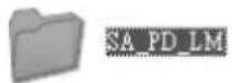
Locate the SA_PD_LM folder from the "Drivers" folder in the Local Disk (C:) of your POS terminal
-
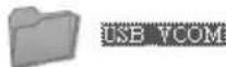
Double click the USB_VCOM folder.
-
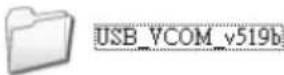
Double click the USB_VCOM_v519bx folder.
-
In the folder, double click the PDF file with the filename of USB VCOM Drivers Installing Guide to open it.
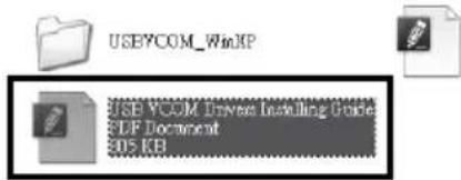
- Then, refer to the following instructions to complete the installation.
Setting up the PD-6X07 Series Customer Display
POS Graphics Display Tool is a helpful tool designed to assist PD-6X07 series users in managing the customer display settings according to your personal preference. To start with the tool, you will need to access the executable file, GraphicsDisplay_Setup Tool.exe, under the directory C:\Drivers\ SA_PD_LM\ GraphicsDisplay_Setup Tool. As for the more detailed instructions on the operation of the tool, please refer to the file named by PD6X07 Setup Tool Guide.pdf in the same directory.
Before using the tool to configure the display, ensure that you have installed the Microsoft .NET Framework 3.5 or above. Also, to avoid users from damaging the main board of the display, it is highly recommended that the configuration is implemented by professional technicians.
Specifications
| PD-6X07R/ PD-6X07R-AR | PD-6X07U/ PD-6X07U-AR | |
| Display | ||
| Display Type | 7" TFT LCD | |
| Number of Characters | 40 characters x 12 rows max. for Alphanumerical characters (PD-6X07R/ PD-6X07R-AR/PD-6X07U/ PD-6X07U-AR)20 characters x 12 rows max. for Chinese characters (PD-6X07R/ PD-6X07U) | |
| Dot Matrix /Resolution | 800 x 480 display resolution | |
| Display Color | Font : Red / Green / Blue / Yellow / Orange / White / BlackBackground : Black / White / Blue | |
| Multimedia Support | JPEG graphics support | |
| Interface | RS232 | USB |
| Power Supply | Powered by standard COM ports | Powered by standard USB ports |
| Mechanical | ||
| Total Height | 471 mm ( PD-6207 series)124 mm ( PD-6307 series/ PD-6507 series/ PD-6607 series) | |
| Total Width | 221.5 mm ( PD-6207 series)188 mm ( PD-6307 series/ PD-6507 series/ PD-6607 series) | |
| Total Depth | 188 mm ( PD-6207 series)52 mm ( PD-6307 series)55 mm ( PD-6507 series)80 mm ( PD-6607 series) | |
※ The product information and specifications are subject to change without prior notice. To get the detailed information on PD-6X07R/ PD-6X07R-AR/ PD-6X07U/ PD-6X07U-AR, please check this model from Posiflex Global Website (http://www.posiflex.com/en-global/Download/download).
- Customer Display User Manual
- Package Contents
- Product Features
- Views of the PD-6X07 Series
- Mounting PD-6207 Series onto POS Terminal
- Mounting PD-6307 Series onto 15"/17" KS series Terminal
- Mounting PD-6507 Series onto HS series Terminal
- Mounting PD-6607 Series onto XT Series Terminal
- Activating Power to Serial Ports for PD-6X07R/PD-6X07R-AR via BIOS
- Powering ON/OFF PD-6X07 Series
- Installing the Virtual COM Driver for PD-6X07U/PD-6X07U-AR only
- Setting up the PD-6X07 Series Customer Display
Brand : Posiflex
Model : PD-6607
Category : Uncategorized