CDX-10 - Electronic lock Dormakaba - Free user manual and instructions
Find the device manual for free CDX-10 Dormakaba in PDF.


| Product Type | Electronic Keypad Door Lock |
| Brand | Dormakaba |
| Model | CDX-10 |
| Dimensions (Exterior) | Approx. 2.8 x 4.7 x 1.2 inches (71 x 119 x 30 mm) |
| Dimensions (Interior) | Approx. 2.8 x 4.7 x 1.2 inches (71 x 119 x 30 mm) |
| Weight | Approx. 2.2 lbs (1.0 kg) |
| Power Supply | 4 x AA Alkaline Batteries (DC 6V) |
| Battery Life | Up to 12 months (based on 10 operations/day) |
| Low Battery Warning | Visual and audible indicator |
| Keypad Type | Backlit Illuminated Keypad |
| User Capacity | Up to 100 user codes |
| Code Length | 4-10 digits |
| Operating Temperature | -4°F to 122°F (-20°C to 50°C) |
| Finish | Satin Nickel / Matte Black |
| Backset / Door Thickness | 2-3/8" or 2-3/4" backset; fits 1-3/8" to 2" doors |
| Functions | Keyless entry, auto-lock, privacy mode, temporary codes |
| Security | Anti-pick, anti-bump, ANSI/BHMA Grade 2 certified |
| Maintenance | Clean with soft dry cloth; avoid harsh chemicals |
| Spare Parts | Batteries, mounting screws, strike plate available |
| Repairability | User-replaceable batteries; professional service for electronics |
| Warranty | Limited Lifetime Mechanical; 1 Year Electronics |
| Certifications | FCC, IC, UL, ANSI/BHMA |
| Package Contents | Exterior assembly, interior assembly, strike, latch, screws, manual |
Frequently Asked Questions - CDX-10 Dormakaba
User questions about CDX-10 Dormakaba
0 question about this device. Answer the ones you know or ask your own.
Ask a new question about this device
Download the instructions for your Electronic lock in PDF format for free! Find your manual CDX-10 - Dormakaba and take your electronic device back in hand. On this page are published all the documents necessary for the use of your device. CDX-10 by Dormakaba.
USER MANUAL CDX-10 Dormakaba
INSTALLATION & OPERATING INSTRUCTIONS
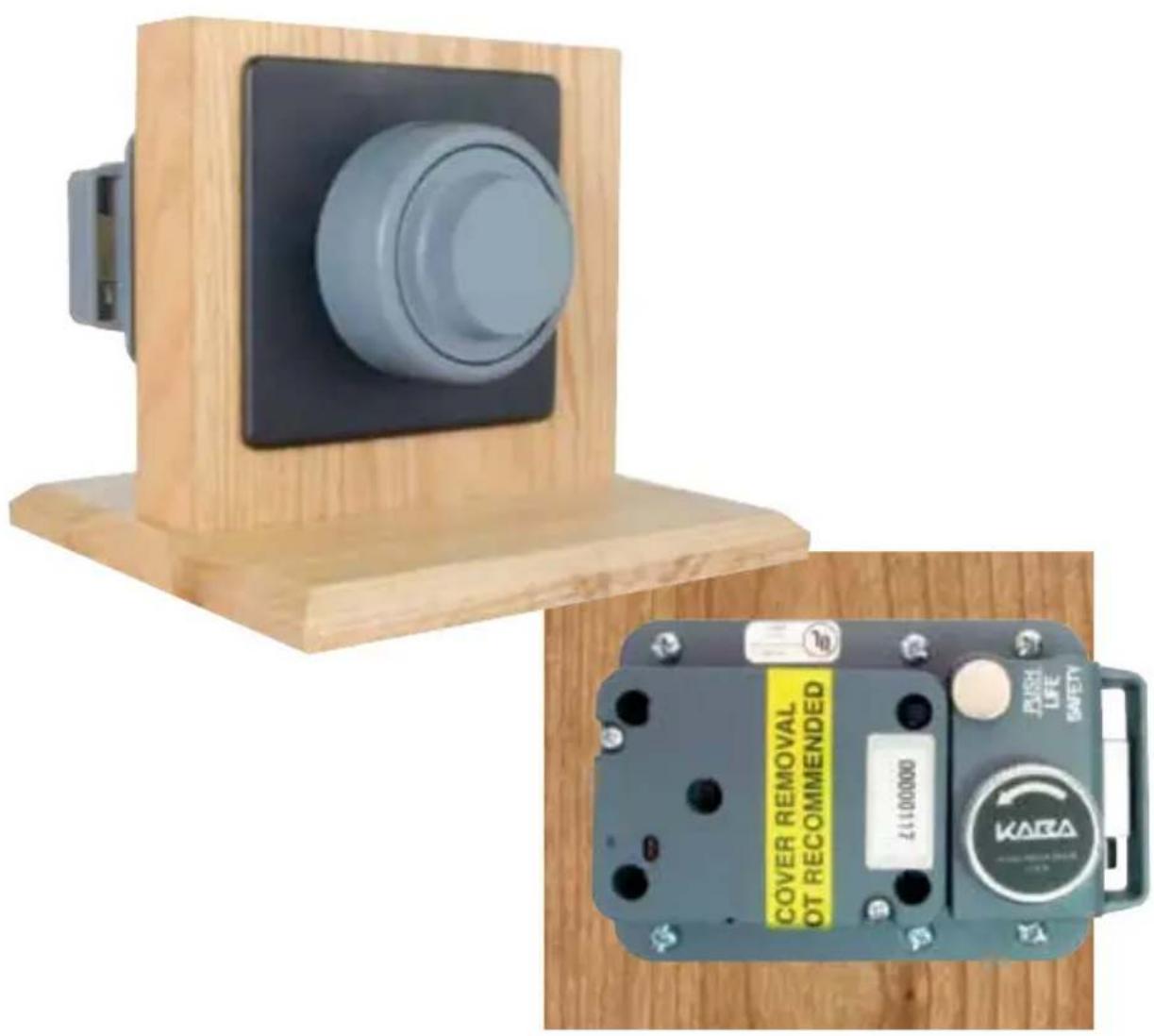
Table of Contents
INTRODUCTION....4
CDX-10 OPERATING INSTRUCTIONS....4
TO OPEN FROM OUTSIDE....4
TO OPEN FROM INSIDE....5
LIFE SAFETY OPERATION.... 5
CDX-10 INSTALLATION....6
BASIC TOOLS NEEDED....6
INSTALLATION KIT CONTENTS.... 7
CDX-10 PARTS FOR INSTALLATION 8
STRIKE INSTALLATION....9
TEMPLATE 9
DEAD BOLT INSTALLATION....9
DIAL RING INSTALLATION.... 10
CUSTOM TUBE AND SPINDLE CUTTING....10
INSTALLATION COMPLETION....10
Technical Support: 1-800-950-4744
INTRODUCTION
The combination door unit can be added to the X-10 lock to form the CDX-10. This adaptation allows you to have access control on any door.
CDX-10 OPERATING INSTRUCTIONS
NOTE: Read all instructions carefully before attempting to INSTALL and operate your CDX-10 Lock Assembly.
The specific instructions for operating the X-10 Combination Lock itself are found in the “Operating Instructions” booklet for the X-10 Type 1F Lock (P/N 539.0512) which is enclosed in this Operating/Installation Instruction Kit.
Please refer also to the Model CDX-10 Lock System drawing (P/N 524.021) for lock nomenclature which is also included in this kit.
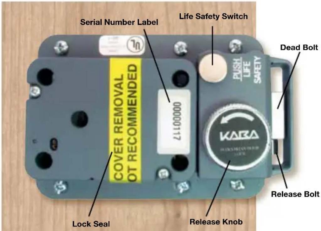
OPENING THE CDX-10
NOTE: When closing the CDX-10, the dead bolt will not extend until the release bolt hits the door strike as the door closes.
TO OPEN THE CDX-10 FROM THE OUTSIDE
- Dial the combination per the instructions in the X-10 "Operating Instructions" booklet.
- Turn the dial to the right (clockwise) to withdraw the lock bolt and pull the dead bolt (Extension Bolt) with it.
TO OPEN THE CDX-10 FROM THE INSIDE
- Turn the release knob to the left (counterclockwise) to withdraw the dead bolt.
The Life Safety Feature (Bolt Stop Assembly) is provided to prevent someone from unintentionally extending the lock bolt.
TO ACTIVATE THE LIFE SAFETY FEATURE
- Turn the dial to the right (clockwise) to withdraw the lock bolt and also the dead bolt (Extension Bolt).
NOTE: The life safety switch can only be depressed while the lock bolt is withdrawn.
- Depress the life safety switch, located by the LIFE SAFETY label on the dead bolt, until it latches.
ATTENTION: To ensure engagement of the life safety switch, fully rotate the release knob counterclockwise and hold in that position. Then depress the life safety switch.
Once the Life Safety Feature is activated, the life safety switch blocks the lock bolt and prevents the dead bolt from latching when the door is closed.
TO DEACTIVATE THE LIFE SAFETY FEATURE
- Pull the life safety switch outward to release the bolt stop.
CDX-10 Installation Instructions
Please read all instructions carefully before you install and use your CDX-10 Lock Assembly. This will help you avoid unnecessary costs and concerns resulting from improper installation.
BASIC TOOLS NEEDED
- Medium Phillip's screwdriver (#1/#2).
- Standard hacksaw (32 teeth/inch).
- Small flat file.
- Small vise or a Port-A-Vise (Harbor Freight P4742).
- Drill bits: No. 25, 11/32", 1/2".
- Electric hand drill.
- 3/32" hex key.
- 11/32" Nut driver.
Recommended but not required:
- Torque screwdriver (30 inch-pound capacity).
NOTE: See Table Of Recommended Torques For The Various X-10 Lock Screws (Page 1, Installation Instructions For the X-10 Type 1F High Security Electronic Lock).
INSTALLATION KIT CONTENTS

- Rubber Vise Clamp
- Saw Blade (52 teeth/inch)
- Saw Handle
- Tube Deburr Stone
- Outer Tube
- Inner Tube
- Lock Case Mounting Screws (Two sets; 4 each, English and Metric)
- Stick-on Cable Guides (3)
- Zebra Connector & Zebra Connector Housing*
- Lubricant (Lubriplate)
- Dial Hub Locating Gauge
- Hex Key (5/64")
- Spindle Screw
*The Zebra Connector and Zebra Connector Housing are assembled at the factory but may come apart during shipment.
-
CDX-10 to door mounting screws, pan head #10 x 1.25, Type AB (2) - not shown.
-
Dial ring to exterior mounting plate mounting screws, pan head #8-32 x 5/16 (2) (Packaged with exterior mounting plate - used with exterior mounting plate) not shown.
-
CDX-10 exterior mounting plate attaching screws, pan head #10-32 X 1.25 (4). (Packaged with exterior mounting plate) - not shown.
CDX-10 PARTS FOR INSTALLATION
- CDX-10 Dead bolt lock assembly
- CDX-10 Base hardplate
- Dial hub assembly
- Strike Kit (1 of 4 Types: 1, 2, 3 or 9; Strike #9 is shown in photo with screws)
- Spindle
- Dial ring assembly
- Exterior mounting plate cover
- Exterior mounting plate

STRIKE INSTALLATION
- Refer to the enclosed Strike Information Sheet for your specific strike mounting details.
- Mount the strike on the door jamb at a convenient height above the floor. This should not exceed 47 inches from the floor to the center of the strike.
- Make sure the strike is mounted so its bolt opening is parallel to the face of the door and positioned to allow for the bolt elevation from the face of the door. REFER TO THE "INSTALLATION DETAIL TEMPLATE". Please note that the 7/8" dimension includes the 0.125" thick hardplate.
TEMPLATE
An “INSTALLATION DETAIL TEMPLATE” with dimensional information is included in this kit. An actual size, cardboard, cut-out template is also included for your convenience.
DEAD BOLT INSTALLATION
- Use the center of the strike as a reference to position the cardboard TEMPLATE on the door.
NOTE: The door must be ajar and free to swing while positioning the template to the strike and the door.
- Fit the strike opening of the template over the strike (i.e., center the strike in the opening) and tape the template to the door.
- Center punch all hole positions onto the door.
- Drill the 1/2" diameter spindle hole through the door.
- Drill the two (2) CDX-10 attaching screw holes nearest the strike opening (No. 25 drill, 0.149" diameter). Drill holes only 1.25" deep. DO NOT
DRILL THROUGH.
-
Drill the other four (4) CDX-10 attaching screw holes (11/32" drill, 0.344" diameter) through the door. The Exterior Mounting Plate posts will extend into these holes from the opposite side of the door.
-
Install the inner cable tube onto the X-10 lock case. Refer to the "Installation Instructions for the X-10 Type 1F High Security Electronic Lock."
-
Remove the protective padding from the end of the cables.
-
Place the outer tube over the cable and onto the tube retainer on the back of the lock case with the flared end toward the lock case.
-
Place the 3.5 X 5 x 1/8" hardplate against the back of the CDX-10 base.
-
Feed the cable and outer tube through the 1/2" hole in the door while positioning the CDX-10 and hardplate against the door. Insert the two (2) #10 screws nearest the strike opening to attach the CDX-10 and hardplate to the door.
-
Position the Exterior (Dial ring) Mounting Plate and insert the four (4) #10-32 x 1.25 pan head machine screws. Longer or shorter screws may be required depending on door thickness as follows:
DOOR THICKNESS: SCREW LENGTH:
1.25 1.00
1.375 - 1.75 1.25 (PROVIDED)
1.875 - 2.00 1.50
2.125 - 2.50 2.00
2.625 - 3.00 2.50
3.125 - 3.50 3.00
3.625 - 4.00 3.50
4.125 - 4.50 4.00
DIAL RING INSTALLATION
-
Place the exterior (dial ring) mounting plate cover over the exterior (dial ring) mounting plate and mount the dial ring using the two #8-32 x 5/16 machined screws that are provided.
-
Refer to the section on installation of the dial ring in the "INSTALLATION INSTRUCTIONS FOR THE X-10 TYPE 1F HIGH SECURITY ELECTRONIC LOCK" booklet for additional dial ring installation instructions.
CUSTOM CUTTING TUBES AND SPINDLE
- Refer to the sections for cutting tubes and for cutting the spindle in the "INSTALLATION INSTRUCTIONS FOR THE X-10 TYPE 1F HIGH SECURITY ELECTRONIC LOCK" booklet for detailed instructions needed to cut the tubes and spindle to fit your specific installation.
INSTALLATION COMPLETION INSTRUCTIONS
- Continue to follow the instructions in the "INSTALLATION INSTRUCTIONS FOR THE X-10 TYPE 1F HIGH SECURITY ELECTRONIC LOCK" booklet for the remainder of the lock installation. Please note that when those instructions refer to the lock case assembly, the installer should consider that as meaning the CDX-10 unit.
DO NOT REMOVE THE X-10 LOCK CASE FROM THE CD BASE.
NOTICE: The information in this manual is subject to change without notice and does not represent a commitment on the part of Kaba Mas. Kaba Mas shall not be liable for technical errors or omissions contained herein; nor for incidental or consequential damages resulting from the furnishing, performance or use of this material.
© 2012 - 2015 Kaba Mas
X-10 is a Trademark of Kaba Mas
All rights reserved.
KARA®
MAS
Kaba Mas LLC
749 W. Short Street, Lexington, KY 40508 USA
Phone: (859) 253-4744 • FAX: (859) 255-2655
Technical Support: (800) 950-4744
www.kaba-mas.com
- INSTALLATION & OPERATING INSTRUCTIONS
- Table of Contents
- INTRODUCTION....4
- CDX-10 OPERATING INSTRUCTIONS....4
- CDX-10 INSTALLATION....6
- INTRODUCTION
- CDX-10 OPERATING INSTRUCTIONS
- OPENING THE CDX-10
- TO OPEN THE CDX-10 FROM THE OUTSIDE
- TO OPEN THE CDX-10 FROM THE INSIDE
- TO ACTIVATE THE LIFE SAFETY FEATURE
- TO DEACTIVATE THE LIFE SAFETY FEATURE
- CDX-10 Installation Instructions
- BASIC TOOLS NEEDED
- Recommended but not required:
- INSTALLATION KIT CONTENTS
- CDX-10 PARTS FOR INSTALLATION
- STRIKE INSTALLATION
- TEMPLATE
- DEAD BOLT INSTALLATION
- DRILL THROUGH.
- DOOR THICKNESS: SCREW LENGTH:
- DIAL RING INSTALLATION
- CUSTOM CUTTING TUBES AND SPINDLE
- INSTALLATION COMPLETION INSTRUCTIONS
Brand : Dormakaba
Model : CDX-10
Category : Electronic lock