ES96 - Electronic lock Dormakaba - Free user manual and instructions
Find the device manual for free ES96 Dormakaba in PDF.


| Product Type | Electronic Lock |
| Brand | Dormakaba |
| Model | ES96 |
| Dimensions (H x W x D) | Approx. 150 mm x 50 mm x 30 mm |
| Weight | Approx. 1.2 kg |
| Power Supply | 4 x AA batteries (6V DC) |
| Battery Life | Up to 1 year (typical usage) |
| Low Battery Warning | Audible and visual indicator |
| Key Override | Mechanical key included |
| User Capacity | Up to 100 user codes |
| Locking Mechanism | Motorized deadbolt |
| Compatibility | Standard wooden and metal doors (thickness 35-60 mm) |
| Mounting Type | Surface mount or mortise (depending on kit) |
| Operating Temperature | -20°C to +60°C |
| IP Rating | IP54 (dust and splash water protected) |
| Main Functions | Keypad entry, remote access (optional), audit trail, passage mode |
| Security Features | Anti-tamper alarm, auto-lock, encryption |
| Maintenance | Clean with dry cloth; check battery annually |
| Spare Parts Available | Batteries, screws, faceplate, key override kit |
| Repairability | Modular design; user-replaceable battery and keypad |
Frequently Asked Questions - ES96 Dormakaba
User questions about ES96 Dormakaba
0 question about this device. Answer the ones you know or ask your own.
Ask a new question about this device
Download the instructions for your Electronic lock in PDF format for free! Find your manual ES96 - Dormakaba and take your electronic device back in hand. On this page are published all the documents necessary for the use of your device. ES96 by Dormakaba.
USER MANUAL ES96 Dormakaba
| Standard Parts: |
| Insert |
| Deadbolt Keeper |
| Deadbolt Plug |
| Deadlatch Ramp (Auxiliary Bolt Bracket) |
| Keeper Sliding Shims: 1/16" (1.5mm) and 1/8" (3.0mm) |
| A Centerline Latch Faceplate and an Offset Latch Faceplate are provided. Both are: 4-7/8" x 1-1/4" (123.8mm x 31.8mm) |
| Trim Plate |
| 12VDC or 12 to 24VAC Cable Connector |
| 24VDC Cable Connector |
| Anti-Tamper Security Screws (2x 12-24) and Bit |
| Mounting Tab Kit (2x tabs, 4x shims and 5x 12-24 screws) |
| Inductive Kickback Suppressor - MOV |
| Accessories: |
| 96LM Latch Monitor : 08116660 |
| UL 294 Performance Ratings: |
| Access Control Line Security : Level I |
| Destructive Attack : Level I |
| Endurance : Level IV |
| Standby Power : Level I |
The ES96F fail secure locking mechanism shall only be installed where allowed by the local authority having jurisdiction and shall not impair the operation of the panic hardware or intended operation of the emergency exit.
Wiring Instructions
Use the appropriate wire harness supplied.
12V for 12VDC & 12-24VAC*
24V for 24VDC only
Attach the red wire to (+) positive of the power supply.
Attach the black wire to the (-) negative of the power supply.
If using AC power, polarity is not observed.
To meet BHMA A156.31, install the MOV provided across the positive and negative wires or terminals of the harness. The MOV is not polarity sensitive.
NOTE: If a suppression diode is required for access control, observe proper polarity.
Latch Monitor Wires
Black = Common (C)
Blue = Normally Closed (NC)
Orange = Normally Open (NO)
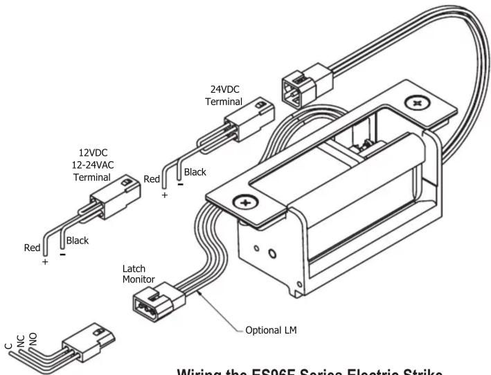
Wiring the ES96F Series Electric Strike
Model ES96F must be connected to a compatible UL Listed Burglary or Access Control Power Supply.
Frame Prep Dimensions
| MEASUREMENT | FRACTIONAL INCHES | DECIMAL INCHES | METRIC mm |
| A 1-1/4" 1.250 31 | 75 | ||
| B 4-7/8" 4.875 12 | 3.83 | ||
| C 3-3/8" 3.375 85 | 73 | ||
| D F + 1-7/16" F | + 1.438 F + 36.51 | ||
| E 3/8" 0.375 9.53 | |||
| F 3/16"* 0.188* 4.76* | |||
| G -11/16" 1.688 | 42.86 | ||
| X Vertical Centre Line of Door Lock and Mounting Face Plate** | |||
| K 4-1/8" 4.125 10 | 4.78 | ||
| M 12-24 N/A | N/A | ||
| Z 3-5/16" 3.3 | 15 84.14 | ||

NOTE: Specifications subject to change without notice.
* Dimension F is measured from face of mounting tab to face of frame.
** Dimension X on the drawing is determined by the vertical centerline of the door. If the latch incorporates a deadlocking pin additional steps will be necessary to ensure proper operation of the deadlocking pin. Measure the thickness of the deadlocking pin and add this thickness to Dimension X to relocate the vertical centerline an appropriate distance on the frame.
Special Features
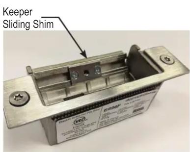
Horizontal Adjustment: If there is play in the door when closed; the keeper shims may be used to minimize play.

Trim Plate: This can be used in case the frame cutout is bigger than required.
For Cutting ANSI Prep Frames
- Place the folded template square to the frame. Horizontally align holes marked on the template with the mounting holes in frame.

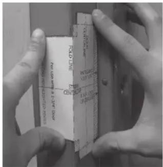
- Peel adhesive backing and paste the folded template square to the frame.

- Carefully cut the frame inside the un-shaded area marked on the template. Install strike per installation instructions ISF2


Deadbolt Plug
Cylindrical


Deadbolt Plug: If the lock set doesn't have a deadbolt, then replace deadbolt keeper with deadbolt plug.
NOTE: Deadlatch Ramp also acts as a Keeper stop, so don't forget to insert it for centerline cylindrical lock applications.
For Cutting Frames without ANSI Prep
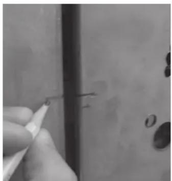
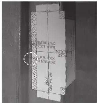
- Mark the horizontal Lock Body Centerline on the door. Close the door and transfer the Lock Body Centerline to the frame.
If the door isn't flush to the frame in the closed position, mark the depth of the closed door on the frame. Measure half of the door thickness back toward the door stop and mark the vertical Door Centerline on the frame.
- Horizontally align the proper Template Lock Centerline with the Lock Body Centerline marked on the frame. Peel adhesive backing and paste the folded template square to the frame.
If the door isn't flush to the frame when closed, tear the template at the fold line. Align the faceplate portion vertically with the Door Centerline and match the template Lock Centerline with the Lock Body Centerline marked on the frame. Carefully paste the front portion of the template on face of frame to align with the faceplate portion.
- Carefully cut the frame inside the un-shaded area marked on the template. Follow Mounting Tab Installation Instructions.



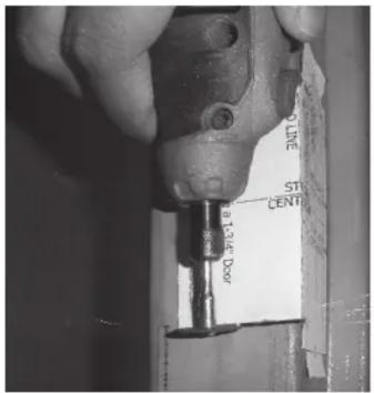

a) Fasten the mounting tabs to the faceplate of the strike, selecting the appropriate shims for the installation.
b) Using the assembled strike and tabs as a template, place against the frame and mark the mounting hole locations. Remove and drill a 3/16" hole in frame for each mounting tab and countersink the frame.
c) Remove the tabs from the faceplate and install in the frame using the 12-24 x 3/8" machine screws supplied. Tabs are plated and drilled and tapped for this purpose.
d) Install strike per page 4 mounting instructions.
Strike Mounting Instruction
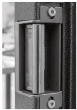
- Mount the strike into the frame without the faceplate. Tighten the mounting screws just enough to hold the strike in place; you may need to slide it up-down for adjustment.
Adjust Deadbolt Keeper:
First, extend the deadbolt and move the door so that deadbolt touches the keeper.
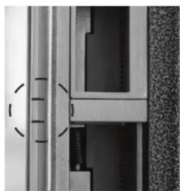
Mark deadbolt limit lines on strike keeper.
Then, open the door and retract the deadbolt. Adjust the deadbolt keeper position so that it aligns with deadbolt limit lines marked on keeper. Move the strike up-down if needed.
Adjust Deadlatch Ramp:
First, move the door towards the strike so that the deadlatch touches the keeper.
Mark deadlatch limit lines on keeper.
Then, open the door. Adjust the deadlatch ramp so that it aligns with deadlatch limit lines marked on keeper.
Adjust Plug-in Latch Monitor (Accessory):
First, move the door towards the strike so that the latch touches the keeper.
Mark latch limit lines on keeper.
Then, open the door. Mount the Latch Monitor on the strike housing so that it is between the latch limit lines marked on keeper.
-
Mark strike position on the frame.
-
Peel the adhesive backing from tape on the back side of the appropriate faceplate. Remove the strike mounting screws. Hold the strike in position as marked on frame.
Carefully position the faceplate onto the strike and secure to the frame.




Brand : Dormakaba
Model : ES96
Category : Electronic lock