
FREE-E - Solar panel DIMPLEX - Free user manual and instructions
Find the device manual for free FREE-E DIMPLEX in PDF.


| Product Type | Solar PV Energy Diverter for Water Heating |
| Brand | Dimplex |
| Model | Free-E (Master Module: DOMM 056849, Meter: DOEE 054722) |
| Dimensions (Master Module) | 316 x 279 x 110 mm |
| Weight (Master Module) | 3.7 kg |
| Dimensions (Meter) | 231 x 125 x 48 mm |
| Weight (Meter) | 0.201 kg |
| Power Supply | 230 V ~ 240 V, 50 Hz, single phase |
| Nominal Power | 3 kW (max load 3 kW, min load 150 W) |
| Efficiency | Up to 98.2% |
| Main Functions | Diverts surplus PV energy to immersion heater; monitors import/export; timed boost; LCD display shows diverted power; RF communication between modules |
| Safety Features | Software alarm, thermal protection, overload protection, soft start, CE approved |
| Wireless Technology | Dimplex GFSK at 868 MHz, 4 channels; WiFi IEEE 802.11 b/g/n (Master only) |
| Operating Temperature | -20°C to +45°C |
| Operating Humidity | Up to 85% non-condensing |
| Maintenance | Clean fan and ventilation grids with vacuum cleaner; disconnect AC and wait 5 minutes before cleaning |
| Spare Parts / Repairability | No user-serviceable parts; repair only by qualified personnel; routine fan cleaning only |
| Warranty | 3 years from date of purchase |
| Certification | CE, EMC compliant, Low Voltage Directive, R&TTE |
| Intended Use | Domestic and light commercial; must be installed indoors by qualified electrician |
Frequently Asked Questions - FREE-E DIMPLEX
User questions about FREE-E DIMPLEX
0 question about this device. Answer the ones you know or ask your own.
Ask a new question about this device
Download the instructions for your Solar panel in PDF format for free! Find your manual FREE-E - DIMPLEX and take your electronic device back in hand. On this page are published all the documents necessary for the use of your device. FREE-E by DIMPLEX.
USER MANUAL FREE-E DIMPLEX
Free-E Installation Manual
Heat water for free with solar PV.
Contents
-
Manual Information 5
-
Safety Information 7
2.1 Legionella Warning 7
2.2 General Safety Guidelines 7
2.3 General Maintenance Guidelines 7
2.4 Electrical Safety Guidelines 8
2.5 Legal 9
2.6 Intended Use 9
- Free-E Overview - How it Works 10
3.1 Key Features 12
3.2 Installation Manual Overview 13
3.3 Scope of Delivery 14
3.4 Location and Explanation of Labels 15
- Installation Information 16
4.1 Dimensions and Clearance 16
4.2 Mounting Instructions 17
4.3 Electrical Information 20
4.3.1 Free-E Master Module (IGBT Board) Connections 21
4.3.2 Free-E Meter Connections 22
4.3.3 Installing the CT Clamp 23
4.3.4 Using an External Control 24
4.3.5 LED Status Information 24
4.3.6 Schematic Information 25
4.4 User Interface Settings and Commissioning 27
5 Appendices 31
6 Consumer Information 42
1. Manual Information
Warnings and Icons Used

Electrical Warnings
Indicates any hazard of an electrical nature.

General Warnings
Indicates a general warning against actions which could result in damage to the system or personal injury to the installer and/or user.

Information
Indicates tips and advice for the smooth operation of the system.
THIS MANUAL REFERS TO THE FOLLOWING PRODUCTS;
Free-E Meter (certified as part number: 054722)
Free-E (certified as part number: 056849)

Retain This Manual For Information
The instructions and maintenance information included in this manual are important for the correct installation and use of Dimplex Free-E. Please ensure that you retain this manual for reference.
THIS MANUAL IS INTENDED FOR QUALIFIED ELECTRICIANS ONLY
This manual is intended for electricians installing Dimplex Free-E systems.
All electricians must have prior knowledge regarding the installation of Dimplex Free-E systems, and must be competent to install the system safely and successfully.
Electricians must have knowledge of any local or national standards, codes or regulations that may apply, as well as safe methods of practice. Dimplex accept no responsibility for compliance with these codes and regulations on the part of the installer.
All electrical installations must be carried out in accordance with local and national standards and regulations, including BS 7671 for UK installations.
The specifications and information supplied in this manual may be subject to change without notice at the discretion of Dimplex. All attempts have been made to ensure that this document is complete and that the information supplied is correct at the time of publication, however Dimplex will assume no responsibility for damages (including consequential and indirect / accidental damages) resulting from reliance on the information presented in this document.
The Free-E and Free-E meter contain no serviceable parts, with the exception of routine cleaning of the fan.
Repair should not be attempted by unqualified persons.
2. Safety Information
2.1 Legionella Warning
Legionella bacteria can be found in natural water sources in low concentrations. At this level it will not pose a risk to human health, however the nature of domestic hot water storage tanks or boilers may allow the bacteria to reproduce if the water is left stagnant for a long time.
Under normal circumstances, the frequent use of the hot water tank will protect against the growth of bacteria, however if the tank will be left unused for a prolonged period, for example, if you are going on holiday, it is highly recommended to ensure that any boiler controls are set to heat the water to 60^ C+ at least once per week to protect against Legionella.
2.2 General Safety Guidelines
This appliance is not intended for use by persons (including children) with reduced physical, sensory or mental capabilities, or lack of experience and knowledge, unless they have been given supervision or instruction regarding the use of the appliance by a person responsible for their safety.
Children should be supervised to ensure that they do not play with the appliance.
All information regarding clearances required for this product and how it should be mounted and fixed are provided in section 4 of this manual.
The Free-E has a software generated alarm which prevents it from running when an error has occurred.
2.3 General Maintenance Guidelines
Regular maintenance of the Free-E ensures a long operating life and optimal efficiency.
The Free-E fan and ventilation grids should be cleaned periodically using a vacuum cleaner.
The following procedure should be followed;
- Disconnect the Free-E on the AC side
- Wait 5 minutes until the residual voltage has been drained and the fan is no longer turning
- Gently clean the top and bottom ventilation grids with a vacuum cleaner
Never use cleaning agents containing sand, soda, acid or chloride, as these can damage the casing of the Free-E.
The LCD display screen should be wiped clean with a soft, dry cloth.
2.4 Electrical Safety Guidelines
The Free-E is suitable for indoor installation only. If the system is installed in an area with high ambient temperatures, greater clearance should be given around the fan vents. Please check the diagrams provided in section 4.1 for dimensions and clearance information.
Before removing the cover of any appliance, please ensure that all electrical circuits are isolated to prevent electrical shocks.
Means for disconnection from the supply mains is incorporated into the fixed wiring of the Free-E in accordance with national wiring regulations.
This device must be installed in accordance with national wiring regulations.
This device is suitable for mains connection only (230V. 1P&N, 50 Hz) and is not suitable for operation with an electrical generator or power modulator, due to possible effects on the electrical supply. Any attempt to do so will void warranty.
Ensure that regulations specified by the local electricity supplier have been adhered to.
Ensure the incoming power supply and distribution board are suitably rated.
The local wiring regulations should always be adhered to, paying particular attention to the mixing of low voltage and extra low voltage cabling.
Ensure that no moisture reaches the inside of the Free-E during installation, as water ingress may cause severe damage. Do not open the Free-E when a high level of humidity is present, and always ensure that the area of installation is dry.
When using electrical devices, there is always a risk of fire or explosion.
To prevent this from occurring please ensure that;
- The Free-E system is not installed close to any flammable materials - The Free-E system is not installed in any areas with potential for explosion.
2.5 Legal
The construction and design of the Free-E complies with all relevant EU directives.
2.6 Intended Use
This product is designed to redistribute energy generated by a PV system to an immersion heater, that would otherwise have been exported to the grid, and is intended for domestic and light commercial use only. Any other use beyond that intended by the manufacturer is prohibited. This requires the user to abide by the manufacturer's product information. Please refrain from tampering with or altering the device.

WARNING
THE AC AND DC CABLES HAVE HIGH VOLTAGES AND POSE A RISK OF ELECTRIC SHOCK OR EVEN DEATH. ONLY CONNECT THE FREE-E SYSTEM AS SHOWN IN THIS MANUAL.
3. Free-E Overview - How it Works
When PV panels generate electricity, the production is initially consumed by electrical appliances or devices in the household that are creating a demand for energy. If the household does not consume all of the energy produced by the PV panels, the surplus energy will be sent to the grid.
The Free-E uses this surplus photovoltaic energy instead to heat the water in a household water tank, and therefore prevent this energy from going to waste. The Free-E is up to 98.2% efficient when using unused (otherwise exported) solar PV electricity to an electrical water heating device. This maximizes the consumption of self-generated solar power and minimizes the cost of buying energy for domestic hot water. It can be retrospectively fitted to homes already with solar PV and a hot water cylinder.
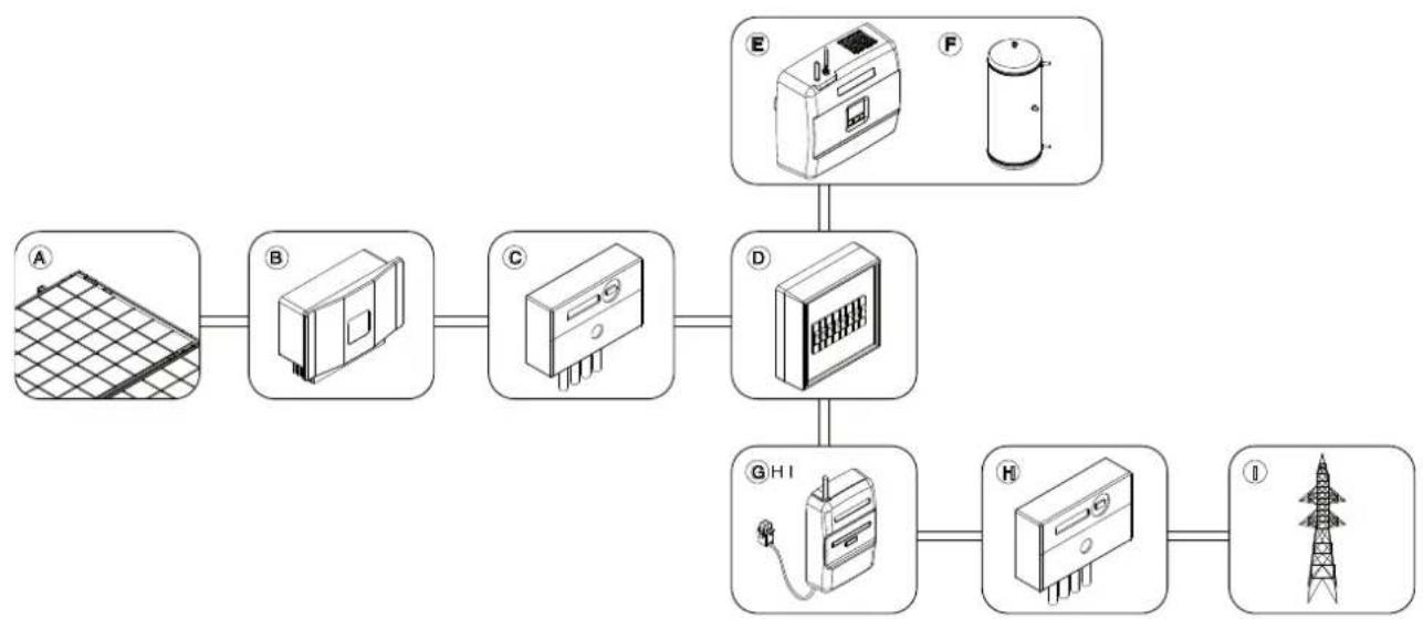
flowchart
graph TD
    A["Grid Grid"] --> B["Battery"]
    B --> C["Cooling Unit"]
    C --> D["Refrigerator"]
    D --> E["Water Heater"]
    E --> F["Cylinder"]
    F --> G["Tower Tower"]
| Position | Description |
| A | PV Panels |
| B | Inverter |
| C | PV Solar Electricity Meter |
| D | Distribution Box |
| E | Free-E |
| F | Domestic Hot Water Cylinder |
| G | Free-E Meter and CT Clamp(s) |
| H | Import / Export Electricity Meter |
| I | Grid |
The amount of hot water that can be generated and stored each day is dependent upon the capacity of the PV array installed and the size of the hot water storage cylinder.
During the summer months when there is more sunlight, more PV energy will be available.
To ensure maximum efficiency of the system, a large enough cylinder must be sized to store the volume of hot water that could be generated by the system.
| PV Array Size | Watts | 1000 | 2000 | 3000 | 4000 |
| Panels | 4 | 8 | 12 | 16 | |
| Volume of hot water generated daily during summer months (60 °C) | litres | 45 | 90 | 135 | 180 |
| Annual volume of hot water generated on an average day throughout the year (60 °C) | litres | 25 | 50 | 75 | 100 |
3.1 Key Features
- Uses excess energy produced by your PV system to heat water.
- Monitors and adjusts the power imported and exported to the grid, ensuring that the exported power remains at virtually zero when the PV system is producing enough energy to cover the demand for domestic electricity and hot water.
- Monitors and adjusts the power imported and exported to the grid, ensuring that the exported power remains at virtually zero when the PV system is producing enoughy energy to cover the demand for domestic electricity and hot water.
- Timed boost function available, which can be set for multiple days of the week.
- Back-lit LCD display with different Light OFF times available, which displays information about the operating mode, settings and more.
- The current imported, exported and diverted power level can be viewed.
- Compatible with most existing immersion heaters and underfloor heating systems.
- Internal software alarm system, thermal protection, overload protection and soft start option - all of which prevent damage to the system and give you peace of mind.
- Approved CE product.
- 3 Year Warranty.
3.2 Installation Manual Overview
Before you begin;
- Read this manual thoroughly
- Check the scope of delivery
- Check safety information
- Ensure that you have access to any required tools or equipment (e.g drills, cable)
1
2
3
Check dimensions and clearance information.
Ensure that the location for the installation is appropriate. See section 4.1.
Mount the devices, make the electrical connections then check that all are fitted securely, screws closed tightly, casings closed, etc. See Section 4.3
Switch on the Free-E, then follow the step by step commissioning procedure provided on the user interface.
Installation Complete!
See User Manual for further information.
3.3 Scope of Delivery
Please ensure that your installation pack is complete and free from damage on delivery. Dimplex will not accept responsibility for any components that are missing or damaged but not reported when the package is first inspected. Note: Accessories are delivered in two small plastic bags, one inside the Free-E Meter box and one inside the Free-E Master box.
If it is necessary to return your pack to us, please use the original packaging.
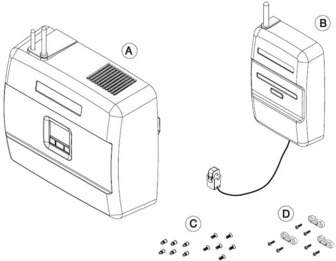
| Position | Description |
| A | Free-E Master Module |
| B | Free-E Meter and CT Clamp (clip on) |
| C | Screw Pack (6x Screws, 6x Wall Plugs) |
| D | 3x Strain Relief Clamps, 6x Screws |

INSTRUCTIONS INCLUDED IN FREE-E PACKAGING
1x User Manual, 1x Installation Manual
PLEASE READ INSTRUCTIONS CAREFULLY BEFORE INSTALLATION INSTRUCTIONS MUST BE RETAINED BY END USER FOR REFERENCE AFTER INSTALLATION
3.4 Location and Explanation of Labels
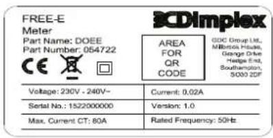
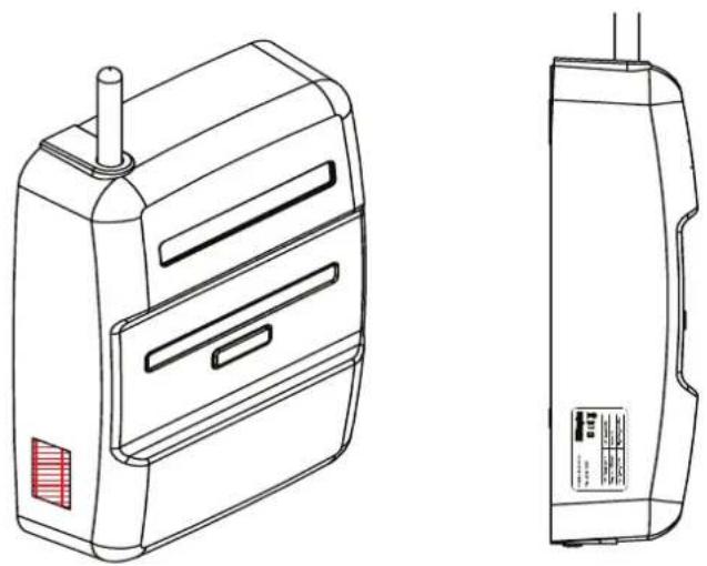
The rating labels given to the Free-E master module and the Free-E meter are located externally on the bottom of the casing, and display the following information as standard;
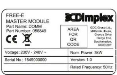
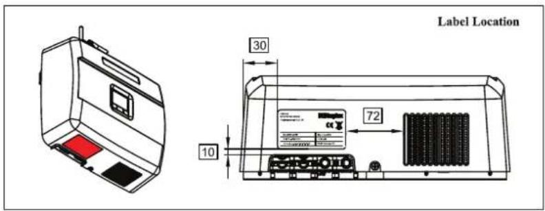
natural_image
Technical line drawing of a device with front and side views, no visible text or symbolsBoth labels contain;
- Nominal voltage
- Serial Number
- Nominal Current
- Version
-Rated Frequency
The master module label also contains the Free-E meter label contains the maximum CT current. For more information about the Free-E, please see the technical specifications sheet included in the appendices section of this manual.
4. Installation Information
4.1 Dimensions and Clearance
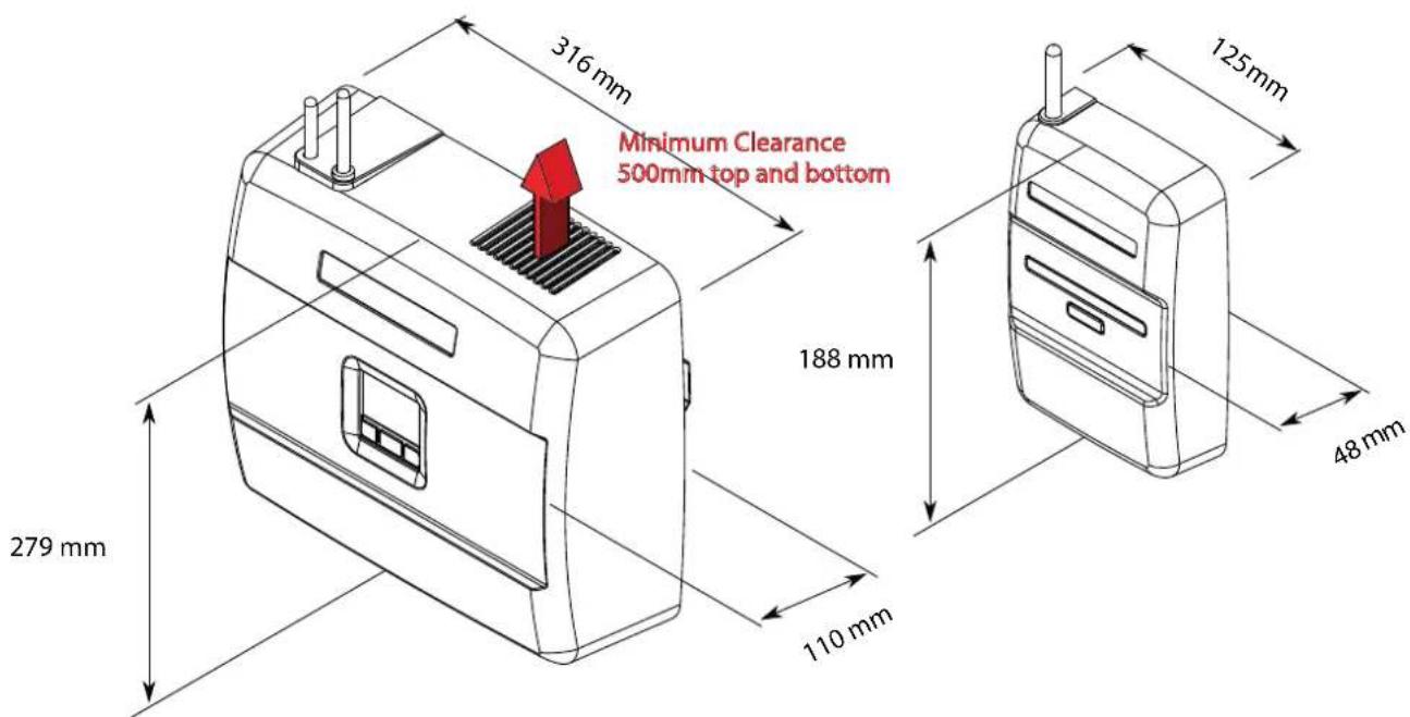
- Because the Free-E (for simplicity, in this manual, the Free-E Master Module is often referred to as the Free-E) contains fan components, it requires space to allow proper air circulation when in use.
- The vent openings in the Free-E casing must not be blocked or covered under any circumstances.
- The minimum clearance dimensions for the fan vents are shown below, along with other key dimensions for the product.
- The Free-E and Free-E meter must be installed indoors and are wall-mountable devices. It is recommended that the devices are installed close to a mains supply to ensure ease of installation.
When selecting a location for the Free-E and Free-E meter installation, proximity to the mains supply, accessibility of the immersion heater supply cable, accessibility of a 16A MCB / 13A fused outlet for the Free-E and 5A fused outlet for the Free-E meter, user access and visibility of the control panel, cables access and ventilation clearances should all be taken into consideration.
4.2 Mounting Instructions
Before installing the Free-E, please ensure that you have observed the following requirements for mounting and fixing;
- Ensure that the wall you have chosen to support the Free-E is stable and can support the weight and size of the box (see Technical Specifications)
- Ensure that enough clearance space is left to allow access for cables
- The user interface of the Free-E should be easily accessible
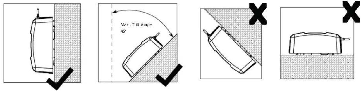
- The Free-E should be installed upright where possible
- The maximum tilting angle for the Free-E is 45^
- Do not install the Free-E tilting forwards
- All cable connection areas should be facing downwards
- Do not install the Free-E horizontally
- The ambient temperature in the area of installation must be below 45°C
- Do not install the Free-E in an area where it will be exposed to direct sunlight
- Due to the inclusion of a fan in the Free-E design, the product may emit a low level of operational noise. Please ensure that the Free-E is not fitted in close proximity to bedrooms or any areas where noise emissions may cause an issue.
- The Free-E is supplied with a pack of screws and wall plugs, which are to be used in the mounting of the product.
For walls which are not standard block walls, e.g. stud walls, special fasteners may be required which are not provided by Dimplex. Please ensure that the fixing method is appropriate for the wall material which the devices are being mounted to.
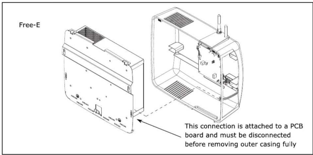
To mount the device on a wall, the outer casing should first be removed by removing the screw at the bottom on the Free-E and sliding the casing up and off.
Because it is necessary to remove the casing of the Free-E and Free-E meter prior to wall-mounting, please ensure that you read the following instructions carefully before attempting to mount the devices.
Inside the Free-E, an electrical board is screwed to the outer casing, however there is an electrical wire connection which also connects the board to the main Free-E body, through a slot in the lower left hand side of the metal enclosure. When removing the outer casing, this connection MUST be disconnected from the main Free-E body to prevent damage. Two similar connections are present in the Free-E Meter, and must be disconnected in the same way before removal of the casing. See diagrams below for more information.
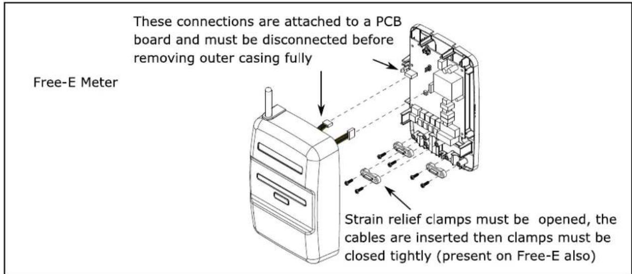
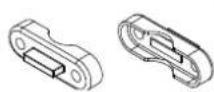
NOTE: Depending on the cable size being used, the strain relief clamps may need to be flipped over to ensure a tight fit. The strain relief clamps are designed to be fitted in either configuration.
Next, the screws should be fitted to the wall using the wall plugs provided. The Free-E and Free-E meter are mounted on these screws. The back plate of the Free- meter is marked with dimensions to help you to measure the required locations for the screws and wall plugs. Diagrams showing approximate dimensions for mounting screw locations for both devices are given below.
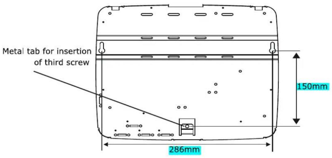
To secure the Free-E, another screw should be fitted through the holed metal tab on the back plate, and into the wall, again using the provided wall plugs.
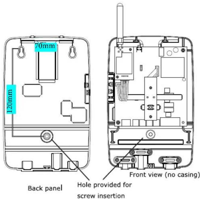
All electrical connections should be made before replacing the casing on both devices. Please see the wiring diagrams and electrical information in this manual for details.
4.3 Electrical Information
The electrical connections required for the installation of the Dimplex Free-E should only be made by persons qualified to do so (see warnings on page 5).
The installation will require removing the casing of the devices involved and should not be attempted by inexperienced persons as there is a risk of electrocution if carried out without the proper precautions.
The Free-E system consists of the Free-E master module and the Free-E meter. To install the system, the necessary electrical wiring connections must be made, and then the commissioning procedure must be carried out using the user interface on the Free-E. The Free-E comes supplied with all the required electrical connectors (see 3.3 Scope of Delivery).
All connections for the Free-E system are single-phase, and immersions / external heaters should not exceed a load of 3kW.

BEFORE OPENING THE DEVICES, ENSURE THAT ALL CIRCUITS ARE ISOLATED. ENSURE THAT THE INTERNAL COMPONENTS DO NOT GET WET DURING INSTALLATION.

IF POWER IS BEING DIVERTED TO A LOAD OTHER THAN AN IMMERSION HEATER, THE LOAD MUST ALSO BE A SIMPLE RESISTIVE LOAD. THIS WILL INCLUDE, FOR EXAMPLE, UNDERFLOOR HEATING, BUT DOES NOT INCLUDE LOADS CONTAINING ELECTRICAL COMPONENTS, E.G. FANS THE LOAD MUST BE ≤3KW AND SHOULD ALSO NOT INCLUDE ANY TIMER FUNCTIONS TO PREVENT DAMAGE FROM THE FREE-E OUTPUT CONTROL.

WHEN REPLACING ANY SCREWS IN THE DEVICES, WHETHER INTERNAL OR EXTERNAL, PLEASE ENSURE THAT ALL ITEMS ARE FIXED SECURELY, AS POOR CONNECTION OR UNPROTECTED COMPONENTS COULD RESULT IN FIRE, INJURY OR DAMAGE TO THE FREE-E OR FREE-E METER.
To maximise the amount of energy the water cylinder can store, it is recommended to increase the immersion thermostat setting to 60^ C. The stored hot water temperature could vary daily depending upon the PV energy available. It is the installers responsibility to consider installing a thermostatic mixer value to stop hot water from scaulding
| Option | Schematic Title |
| Single Heater Or Underfloor Heating (UFH) | Schematic 1 (a,b,c,d) |
The table above provides information about which schematic should be followed.
All of the required schematics are included in this manual in the appendices section.
The Free-E system is simple to install. Both the master module and the Free-E meter have only one cable access point, located at the bottom of each device.
4.3.1 Free-E Master Module (IGBT Board) Connections
The Free-E master module connectors are shown in the diagram below. To make connections to the Free-E, the screws must be loosened, wires must be inserted and then screws must be retightened correctly to ensure that there are no loose connections.
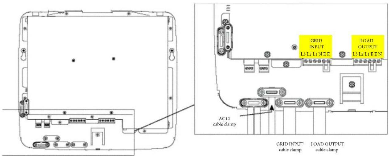
The diagram above shows the 'GRID' and 'LOAD' connections for the Free-E master module. The 'GRID' connections are the Free-E input connections (L3, L2, L1, N, E, E), while the 'LOAD' connections are the Free-E output connections (L3, L2, L1, E, E, N).
Warning: For safety reasons do not remove the two pre-existing earth links on the GRID and LOAD connectors.
Full schematics for the wiring of the Free-E are included in the Appendices section of this manual.
4.3.2 Free-E Meter Connections
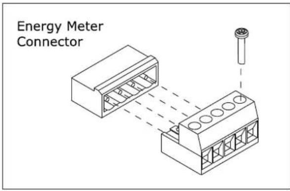
The Free-E meter connector is shown in the diagram above. To make connections to the Free-E meter, the screws must be loosened, wires must be inserted and then screws must be retightened correctly to ensure that there are no loose connections.
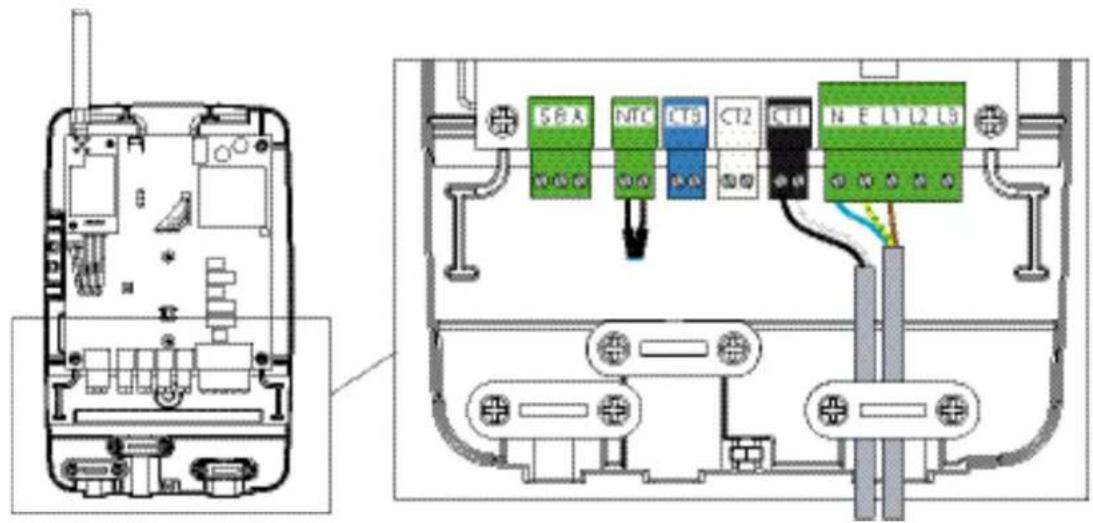
The diagram above shows the connections for the Free-E meter.
4.3.3 Installing the CT Clamp
flowchart
graph TD
    A["CT Energy Meter"] --> B["Earth"]
    B --> C["Neutral"]
    C --> D["DHW Cylinder & Immersion Heater"]
    D --> E["Mains Supply"]
    E --> F["CT Clamp Cable"]
    F --> G["Main to Motor"]
    G --> H["RCD OFF"]
    H --> I["RCD OFF"]
    I --> J["Ground"]
    style A fill:#f9f,stroke:#333
    style D fill:#bbf,stroke:#333
    style F fill:#dfd,stroke:#333
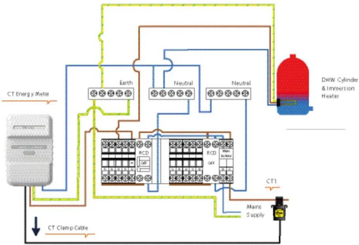
When installing the Dimplex Electricity Meter, it is vital that the CT clamp are installed in the correct configuration, as shown above in the illustration and in the flow chart below;

flowchart
graph LR
    A["Distribution Board"] <--> B["CT1"]
    B --> C["Grid Input"]

For safety reasons, the clamp must always be installed inside the distribution box/enclosure
The labels shown on the CT clamps shows the orientation in which each clamp must be fitted for the Free-E system to function correctly.
- The CT1 clamp must be fitted to the live cable running from the mains electricity meter to the distribution board.
Please ensure that the clamp is closed correctly and is secure in its position.
4.3.4 Using an External Control
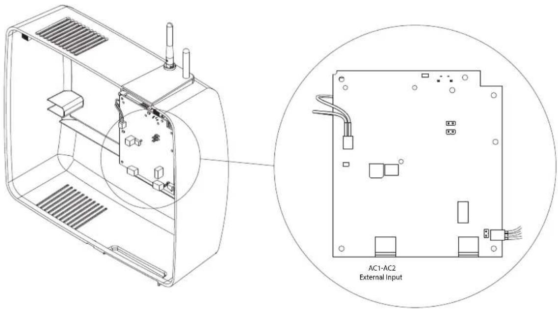
The Free-E unit has an external control input function which allows external devices such as timers and thermostats to force the Free-E output to its fully ON state.
This means that the mains supply will be switched so that it travels directly through the Free-E to the heating load when the external control input is active.
When any AC signal source between 24V\~ and 240V\~ is connected to the 2 pin connector (AC1-AC2 external input shown in the image below), the load is driven fully ON.
When the external control voltage isn't present at pins AC1, AC2 the Free-E unit will return to its normal operating mode.
The wiring to the external control input can be installed at time of first install after or can be added retrospectively.
4.3.5 Schematic Information
When installing the Free-E, it is extremely important to ensure that you have selected the correct wiring schematic for the desired system configuration.
The single heater option should be used where one immersion output is required, e.g. for a standard domestic hot water cylinder.
Single and Dual Tariff schematic options are provided where this is possible. See Appendices 5.3 to 5.6 for full schematics for the wiring of the Free-E.
4.3.6 LED Status Information
| Status LED Blinking Pattern | Details | |
| Mains detected OK | 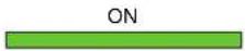 | Green LED ON |
| Mains restarting | ON ON ON ON OFF OFF OFF OFF OFF OFF | Green LED ON for 3 seconds, flashes off for 0.5 seconds |
| Link status establ ished | ON ON ON ON OFF OFF OFF OFF OFF OFF | Green LED ON for 3 seconds, flashes off for 0.5 seconds |
| Link status re-establishing connection |  OFF OFF OFF OFF OFF OFF | Amber LED ON for 3 seconds, flashes off for 0.5 seconds |
| Link status not established - default at power ON |  OFF OFF | Red LED ON |
| Link status connection lost |  OFF OFF OFF OFF OFF OFF | Red LED ON for 3 seconds, flashes off for 0.5 seconds |

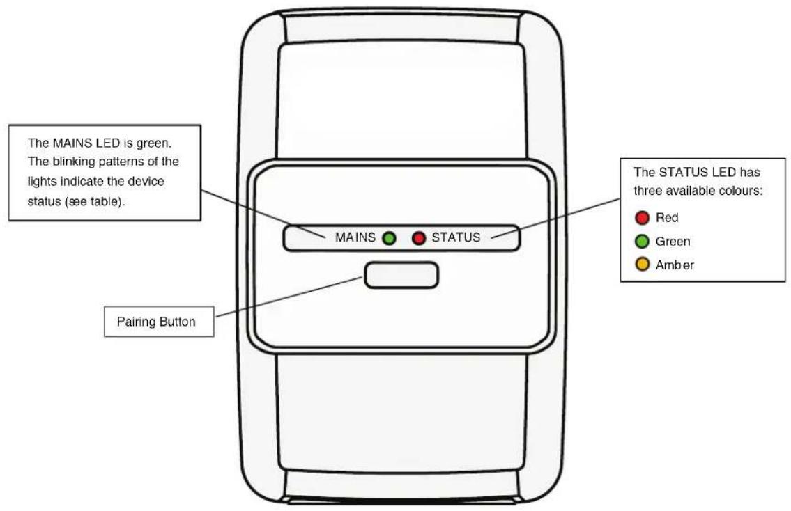
The table above shows the LED blinking pattern on the Free-E meter for each connection status.
The Free-E meter has one Mains LED, which indicates the mains power connection status, and one Status LED, which indicates the communications connection status.
The Mains LED can be in either of two states - a flashing green LED indicates that the Free-E meter has been restarted at the mains, and a solid green LED indicates that the mains connection has been established correctly.
The Status LED can have various states, as it is a tri-colour LED and can display signals in red, amber or green. For the Status LED, a flashing green LED indicates a correctly established connection; a flashing amber LED indicates that the Free-E meter is trying to re-establish a lost connection, and a flashing red LED indicates that the unit has failed to re-establish a connection after 60 seconds.
On the initial installation of the Free-E meter, before there has been a prior connection established, the Status LED will show as a solid red LED. This is the default out-of-box state.
Pairing LED Blinking Patterns
When pairing the Free-E meter to the Free-E during the commissioning routine, Status LED will follow the pattern of flashing amber, however the LED will flash more quickly (every 0.2 seconds rather than 3 seconds then 0.5 seconds).
When pairing is successful, the Status LED will turn green for 3 seconds. If pairing fails, the Status LED will turn amber for 3 seconds.
When the pairing state is finished, the Status LED will return to indicating the communications connection status.
4.4 User Interface Settings and Commissioning
Once the master module and Free-E meter have been fixed in place, electrical connections have been made and the CT clamps have been positioned, the parameters for the system must be set and the commissioning routine completed.
When the Free-E is started up initially, the commissioning routine will begin. If changes need to be made to the commissioning / set-up of the Free-E at a later date, a factory reset will need to be carried out. The steps to carry out this procedure are described in the User Manual.
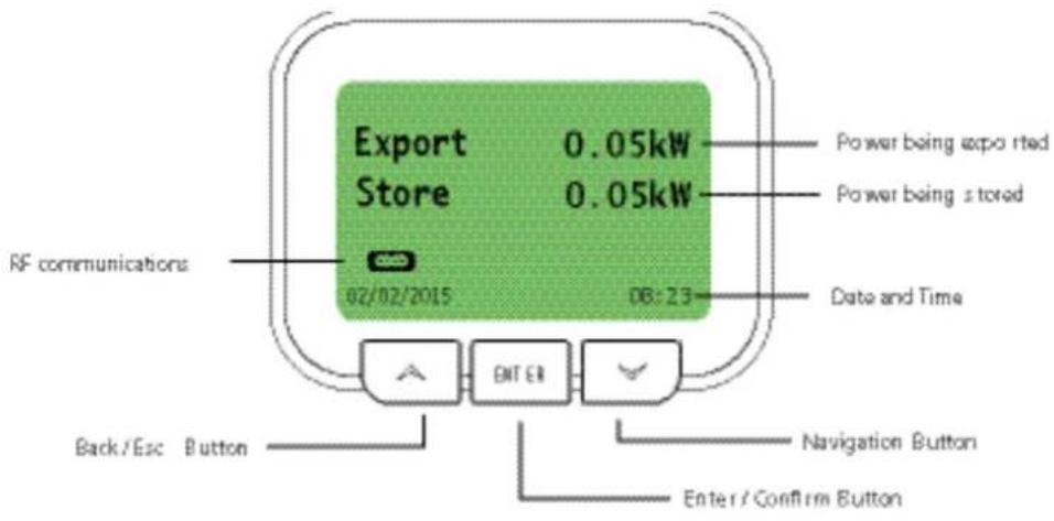
The enter button is used to access the advanced settings menu from the main menu once the Free-E is commissioned (see User Manual for details). It is also the confirmation button for selections made on the user interface.
The left / back button is used to escape from menus or selections.
All navigation up / down through the menus on the user interface will be carried out by using the down / right button. This button allows scrolling down through the displayed options, and when the end of the menu is reached, continuing to press the down / next button will return the user to the top of the menu.
The screen shown above in is the default screen saver on the Free-E user interface. It displays the current energy being diverted in watts, the percentage load diversion (percentage of electricity generated being sent to the domestic hot water cylinder from the Free-E), the current date and time, and icons for the connectivity status, which are;
RF Communication
Displays when the Free-E meter is communicating with the master module, over RF link.
4.4.1 Commissioning the Free-E
When you first start up the Free-E for the first time, or carry out a factory reset, commissioning mode will begin automatically.
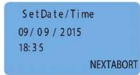
The first screen is the Set Date-Time screen pictured below. The Set Date-Time screen enables you to set the current date and time. This can be modified later by the end user.
Pairing Devices
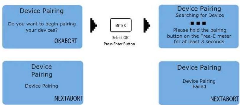
Once the set day-time screen is complete, the device pairing screen will appear.
To continue the commissioning routine by pairing your Free-E with your Free-E meter, select OK, then hold the pairing button on the Free-E meter for 3 seconds (see section 4.3.6).
The Free-E will detect the Free-E meter and will display a confirmation message when complete. This usually takes around 20 seconds.
flowchart
graph LR
    A["Device Pairing\nDo you want to begin pairing your devices?\nOKABORT"] --> B["ENTER\nSelect OK\nPress Enter Button"]
    C["Device Pairing\nSearching for Device\nPlease hold the pairing button on the Free-E meter for at least 3 seconds"] --> B
    D["Device Pairing\nDevice Pairing\nNEXTABORT"] --> B
    E["Device Pairing\nDevice Pairing\nFailed\nNEXTABORT"] --> B
If for some reason the devices do not pair correctly, an error screen will appear to say that pairing has failed. If this should occur, please select Retry and repeat the process, or consult the troubleshooting section if the problem continues.
Select RF Channel
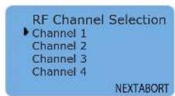
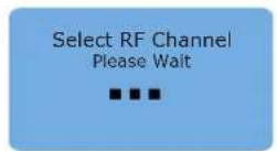
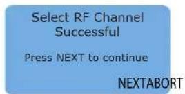
For most installations, there is no need to change the RF channel from the default selection (Channel 1).
If you have difficulty pairing the device, experience problematic interference or have more than one Free-E system installed, you can return to this screen via the user interface after the commissioning procedure to try using a different channel. Please see the user manual for information on how to access the RF channel selection after commissioning.
Load Connection and Schematics
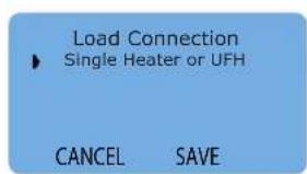
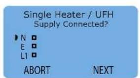
The next step is to choose the load connection schematic. This screen relates to the schematic diagrams provided in the back of this manual, and is dependent upon which type of immersion output has been selected for the installation.
Once you have selected your load connection type, the screen will display various connection checks which must be confirmed for each set-up. These screens provide a checklist as a reminder to check that all the correct connections have been made. Do not confirm that the connections have been made if you are unsure - physically check all connections when carrying out this step.
CT Direction Check
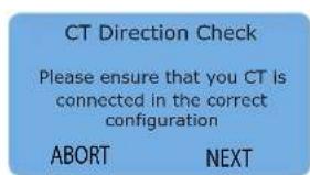
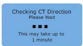
Next the CT direction check will be displayed, and will ask you to confirm that the CT clamp is connected in the right direction.
Ensure that the CT clamp is connected correctly by checking that it is facing in the direction shown in section 4.3.3 then select Next to continue. The software will automatically check the clamp position for you.
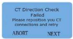
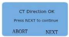
Ensure the Free-E unit is being presented with a real load e.g if a DHW tank is full with hot water, the thermostat may be open and the Free-E unit will be presented with an open circuit.
If the CT clamp is connected in the wrong position, the screen will display an error message and will request that you reposition the clamp before retrying the automated check. If the CT check is successful, the confirmation screen will be displayed.
If the screen continues to show an error message after the clamp has been repositioned and checked, it is possible that the clamp or connection could be faulty. Please see the troubleshooting section of this manual for details.
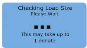
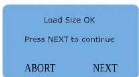
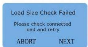
Once the CT check has been completed, the load size check will begin automatically. You should see the messages below on screen while the test is running and then to confirm whether or not it was successful.
Once the load size direction check has been completed, the commissioning procedure is finished and you should see a confirmation screen (shown below), then the Free-E will default to the main user menu. The Free-E is now commissioned and ready for use.

4.4.2 Using External Control Inputs
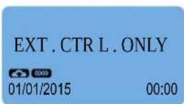
If you are using an external input to the AC1-AC2 connections, it is still necessary to commission the Free-E. Simply commission the system as usual, then make the connections to AC1-AC2 as shown in the appropriate wiring diagram/schematic, and you should see the screen shown below.
5 Appendices
5.1 Appendix 1 - Technical Specifications - Energy Meter
5.2 Appendix 2 - Technical Specifications - Free-E
5.3 Appendix 3 - Schematic 1a
5.4 Appendix 4 - Schematic 1b
5.5 Appendix 5 - Schematic 1c
5.6 Appendix 6 - Schematic 1d
5.1 Appendix 1 - Technical Specifications - Energy Meter
| Ordering Codes | DOEE 054722 | |
| Voltage / Current | Input Voltage RangeVoltage Accuracy +/- 1%Voltage Resolution 0.1 VoltCurrent Measurement Range 0.1 to 80ACurrent AccuracyCurrent Resolution | 100V to 255V AC, 50/60Hz1.6A~4A +/-1.5% 4A~ 80A +/-1%0.01A |
| kWh, PF, kVAh | kWh AccuracykWh ResolutionPower Factor AccuracyPower Factor ResolutionkVAh AccuracykVAh Resolution | +/- 1%0.01 kWh+/- 1%0.01+/- 1%0.01 kVAh |
| Certification | CertificationMetering Standard | CEClass 1 (Accuracy only) |
| Wireless Technology | Radio TechnologyRadio FrequencyChannelsMax Tx PowerRx SensitivityData Rate | Dimplex GFSK868 MHz ISM Band4 Channels (1 - 4)+13dBm-105dBm@25Kbpsup to 25 kbits/sec |
| Wireless Range | Indoor RangeOutdoor Range | up to 50mup to 300m (direct line of sight) |
| Rated input power | Power Consumption | 1 Watt |
| Physical | Dimensions (LxWxH)WeightMountingEnclosureOperating TemperatureOperating Humidity | 231 x 125 x 48 mm0.201 kgWall Mounting FlangesV0 Polycarbonate-20°C to +45°Cup to 85% (non-condensing) |
5.2 Appendix 2 - Technical Specifications - Free-E
| Ordering Codes | DOMM 054739 | |
| Voltage / Current | Input Voltage RangeMaximum continuous AC output current at 210 V 14.2A +/-1%Maximum continuous AC output current at 230 V 13.0A +/-1%Maximum continuous AC output current at 254 V 11.8A +/-1%Maximum output over current protectionMaximum input overvoltage protection 260 VacCooling conceptElectrical Forced Air ConvectionRelay output ratingsRange of output power factorNominal Power factorExternal Input voltage rangePeak Free-E efficiency | 215V to 255Vac, 50/60Hz16A.... 250Vac0.9x ... 1.00.9924 - 230Vac98.2% |
| Wireless Technology | Radio Technology Dimplex GFSKRadio Frequency 868 MHz ISM BandChannels 4 Channels (1-4)Max Tx Power +13dBmRx Sensitivity -105dBm@25KbpsWiFi IEEE 802.11 b/g/n | |
| Wireless Range Indoor | Range up to 50mOutdoor Range up to 300m (direct line of sight) | |
| Standby Power | Power Consumption | 10 Watt |
| Physical | Dimensions (LxWxH)WeightMountingEnclosureOperating TemperatureOperating Humidity | 316 x 279 x 110 mm3.7kgWall Mounting FlangesV0 Polycarbonate-20°C to +45°Cup to 85% (non-condensing) |
| Certifications | CE | Fully EMC Compliant |
5.3 Appendix 3
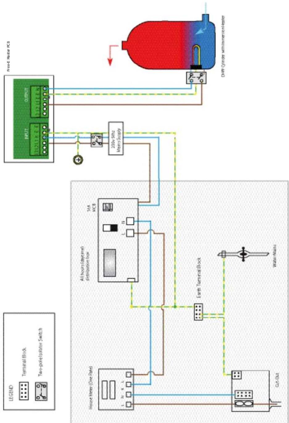
Schematic 1a - Single Heater / UFH (Single Tariff)
flowchart
graph TD
    A["House Meter (One Plate)"] --> B["All hours (daytime) distribution box"]
    B --> C["14A MCE"]
    C --> D["230V SiHz Alarms Supply"]
    D --> E["OUTPUT"]
    E --> F["Free-E Master PCB"]
    G["OHW Cylinder with Inversion Heater"] --> H["Water Main"]
    I["Cut-Out"] --> J["Ground"]
    K["Terminal Block"] --> L["Switch"]
    M["Two-pole Isolator Switch"] --> N["Switch"]
    O["Ground"] --> P["Water Main"]
    Q["Ground"] --> R["Water Main"]
    S["Ground"] --> T["Water Main"]
    U["Ground"] --> V["Water Main"]
Operation
The immersion heater element is wired to output connections N, E and L1 via a double pole isolation switch. Input connections N, E and L1 are also wired using a (separate) double pole isolation switch.
The DHW cylinder/immersion is charged with available excess power until the thermostat set point is reached, causing it to open. Once the thermostat is open, the diverted electricity will begin to be exported rather than diverted to the immersion. The Free-E will display the "STORE FULL" message on the main screen until the set point is no longer being reached (i.e. until one of the thermostats closes again). Once the thermostat is closed, the available excess power will resume diversion to the immersion.
Important!
- Minimum load: 150W
- Maximum load: 3.0kW
- Minimum cable size: 1.5mm ^2 , Recommended: 2.5mm ^2 .
- Must be a simple resistive load without electronic controls
5.4 Appendix 4
Schematic 1b - Single Heater / UFH (Single Tariff) with External Input Control
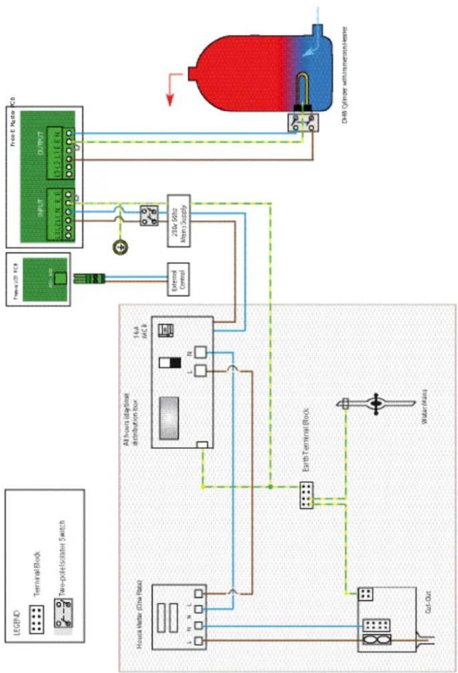
flowchart
graph TD
    A["Two-poleIsolator Switch"] --> B["Terminal Block"]
    B --> C["Housa Meter (One Rate)"]
    C --> D["All hours (day/night) distribution box"]
    D --> E["16A MCB"]
    E --> F["Exterior Control"]
    F --> G["230V 50Hz Main Supply"]
    G --> H["Free-E Motor PCB"]
    H --> I["DHW Cylinder with transmicristor heater"]
    I --> J["Water Main"]
    J --> K["Cut-Out"]
    K --> L["Ground"]
Operation
The immersion heater element is wired to output connections N, E and L1 via a double pole isolation switch.
Input connections N, E and L1 are also wired using a (separate) double pole isolation switch.
The DHW cylinder/immersion is charged with available excess power until the thermostat set point is reached, causing it to open. Once the thermostat is open, the generated electricity will begin to be exported rather than diverted to the immersion. The Free-E will display the "STORE FULL" message on the main screen until the set point is no longer being reached (i.e. until one of the thermostats closes again). Once the thermostat is closed, the available excess power will resume diversion to the immersion.
Important!
- Minimum load: 150W
- Maximum load: 3.0kW
- Minimum cable size: 1.5mm ^2 , Recommended: 2.5mm ^2 .
- Must be a simple resistive load without electronic controls
5.5 Appendix 5
Schematic 1c - Single Heater with Dual Tariff (Economy 7)
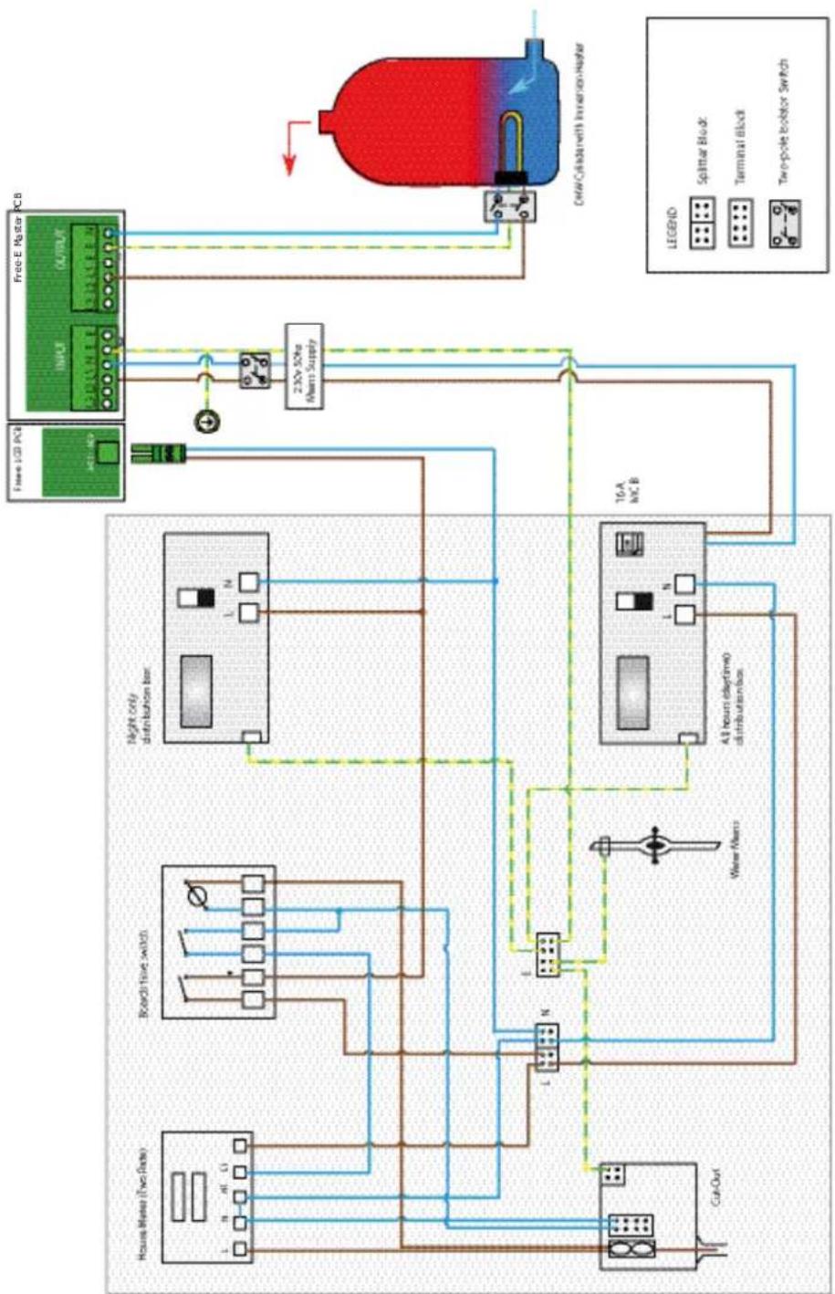
flowchart
graph TD
    A["House Mather (Two Rats)"] --> B["Board Tave switch"]
    B --> C["Night only distribution box"]
    C --> D["16A hC.B"]
    D --> E["All hours (daytime) distribution box"]
    E --> F["Cut-Out"]
    F --> G["Water Mears"]
    G --> H["2.30V 50Hz Mears Supply"]
    H --> I["Free-E Master PCB"]
    I --> J["INPUT"]
    I --> K["OUTPUT"]
    J --> L["2.30V 50Hz Mears Supply"]
    K --> L
    L --> M["CHW Cylinder with Inversion Hadar"]
    style A fill:#f9f,stroke:#333
    style B fill:#ccf,stroke:#333
    style C fill:#cfc,stroke:#333
    style D fill:#fcc,stroke:#333
    style E fill:#cff,stroke:#333
    style F fill:#ffc,stroke:#333
    style G fill:#cfc,stroke:#333
    style H fill:#fcc,stroke:#333
    style I fill:#cfc,stroke:#333
    style J fill:#fcc,stroke:#333
    style K fill:#fcc,stroke:#333
    style L fill:#ffc,stroke:#333
    style M fill:#fcc,stroke:#333
Operation
In this dual tariff set up, the immersion heater element is wired to output connections N, E and L1 via a double pole isolation switch. Input connections N, E and L1 are also wired using a (separate) double pole isolation switch.
The external control input AC1-AC2 is used to connect the necessary electricity meters to regulate the peak/off-peak electricity periods, thus allowing the end user to benefit from off-peak tariff rates when available.
The DHW cylinder/immersion is charged with available excess power until the thermostat set point is reached, causing it to open. Once the thermostat is open, the generated electricity will begin to be exported rather than diverted to the immersion. The Free-E will display the "STORE FULL" message on the main screen until the set point is no longer being reached (i.e. until one of the thermostats closes again). Once the thermostat is closed, the available excess power will resume diversion to the immersion.
Important!
- Minimum load: 150W
- Maximum load: 3.0kW
- Minimum cable size: 1.5mm², Recommended: 2.5mm².
- Must be a simple resistive load without electronic controls
5.6 Appendix 6
Schematic 1d - Dual Tariff with Dual Meters (Off-Peak)
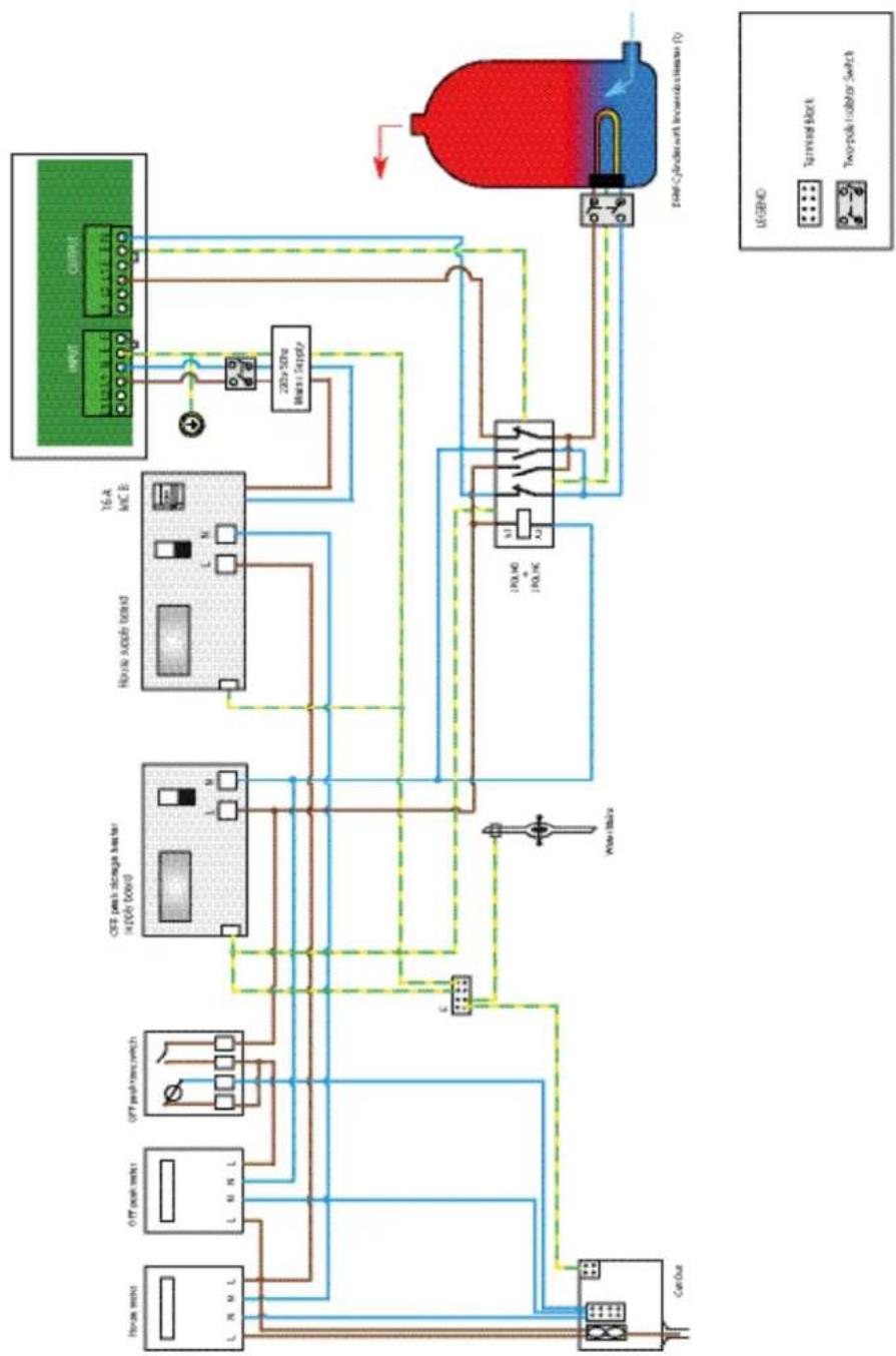
flowchart
graph TD
    A["House motor"] --> B["ON/OFF peak switch"]
    C["Off peak switch"] --> D["ON/OFF peak storage heater supply board"]
    E["House supply board"] --> F["16A inC B"]
    G["200x50Hz blade supply"] --> H["INPUT"]
    H --> I["CURRENT"]
    J["DRM Cylinder with Inverter heater (F)"] --> K["Ground"]
    L["Can/Out"] --> M["Power transformer"]
    N["Water transformer"] --> O["18A HD + 18A INC"]
    P["Tankwell block"] --> Q["LED indicators"]
    R["Two-pole isolator Switch"] --> S["LED indicators"]
Operation
In this dual tariff set up, the immersion heater element is wired to output connections N, E and L1 via a double pole isolation switch. Input connections N, E and L1 are also wired using a (separate) double pole isolation switch.
The external control input AC1-AC2 is used to connect the necessary electricity meters to regulate the peak/off-peak electricity periods, thus allowing the end user to benefit from off-peak tariff rates when available.
The DHW cylinder/immersion is charged with available excess power until the thermostat set point is reached, causing it to open. Once the thermostat is open, the generated electricity will begin to be exported rather than diverted to the immersion. The Free-E will display the "STORE FULL" message on the main screen until the set point is no longer being reached (i.e. until one of the thermostats closes again). Once the thermostat is closed, the available excess power will resume diversion to the immersion.
Important!
- Minimum load: 150W
- Maximum load: 3.0kW
- Minimum cable size: 1.5mm², Recommended: 2.5mm².
- Must be a simple resistive load without electronic controls
6 Consumer Information
6.1 Compliance Information
The Dimplex Free-E complies with the applicable EU directives;
EC Directives:
Low voltage directive 2006/95/EC
EMC directive 2004/108/EC
Radio and Telecommunications Terminal Equipment Directive (1999/5/EC)
Restriction of Hazardous Substances Directive (2011/65/EU)
WEEE Directive
Applied Standards:
ISEN 55014-1: 2006 + A1:2009
ISEN 55014-2: 1997+ A1:2001 + A2:2008
ISEN 55022: 2010
ISEN 61000-3-2: 2006 + A1:2009 + A2:2009
ISEN 61000-3-3: 2008
ISEN 60335-1-2012
6.2 After Sales Service
Your product is guaranteed for 3 years from the date of purchase. Within this period we undertake to repair orreplace this product free of charge (subject to availability) provided it has been installed and operated in accordance with these instructions. Your rights under this guarantee are additional to your statutory rights, which in turn are not affected by this guarantee.
Should you require 24hr sales service you should contact our customer services help desk on 0844 879 3588. It would assist us if you can quote the model number, date of purchase and nature of fault at the time of your call. Please do not return a faulty product to us in the first instance, as this may result in loss or damage and delay in providing you with a satisfactory service.
- Free-E Installation Manual
- Contents
- Manual Information
- Warnings and Icons Used
- Electrical Warnings
- General Warnings
- Information
- THIS MANUAL REFERS TO THE FOLLOWING PRODUCTS;
- Retain This Manual For Information
- THIS MANUAL IS INTENDED FOR QUALIFIED ELECTRICIANS ONLY
- Safety Information
- Legionella Warning
- General Safety Guidelines
- General Maintenance Guidelines
- Electrical Safety Guidelines
- Legal
- Intended Use
- WARNING
- Free-E Overview - How it Works
- Key Features
- Installation Manual Overview
- Scope of Delivery
- INSTRUCTIONS INCLUDED IN FREE-E PACKAGING
- Location and Explanation of Labels
- Installation Information
- Dimensions and Clearance
- Mounting Instructions
- Because it is necessary to remove the casing of the Free-E and Free-E meter prior to wall-mounting, please ensure that you read the following instructions carefully before attempting to mount the devices.
- Electrical Information
- Free-E Master Module (IGBT Board) Connections
- Warning: For safety reasons do not remove the two pre-existing earth links on the GRID and LOAD connectors.
- Free-E Meter Connections
- Installing the CT Clamp
- Using an External Control
- Schematic Information
- LED Status Information
- Pairing LED Blinking Patterns
- User Interface Settings and Commissioning
- Commissioning the Free-E
- Pairing Devices
- Select RF Channel
- Load Connection and Schematics
- CT Direction Check
- Ensure the Free-E unit is being presented with a real load e.g if a DHW tank is full with hot water, the thermostat may be open and the Free-E unit will be presented with an open circuit.
- Using External Control Inputs
- Appendices
- Appendix 1 - Technical Specifications - Energy Meter
- Appendix 2 - Technical Specifications - Free-E
- Appendix 3
- Operation
- Important!
- Appendix 4
- Appendix 5
- Appendix 6
- Consumer Information
- Compliance Information
- After Sales Service
Brand : DIMPLEX
Model : FREE-E
Category : Solar panel