FMB122 - Gps Teltonika - Free user manual and instructions
Find the device manual for free FMB122 Teltonika in PDF.


| Product Type | GSM/GNSS/BLE Terminal (Vehicle Telematics) |
| Model | FMB122 |
| Dimensions (L x W x H) | 65 x 56.6 x 20.6 mm |
| Weight | 55 g |
| Power Supply Input | 10 - 30 V DC (overvoltage protection) |
| Back-up Battery | 170 mAh Li-Ion, 3.7 V (0.63 Wh) |
| Power Consumption (Nominal) | < 34 mA at 12 V (no load) |
| Cellular Technology | GSM/GPRS Quad-band 850/900/1800/1900 MHz |
| GNSS Support | GPS, GLONASS, Galileo, BeiDou, SBAS, QZSS, DGPS, AGPS |
| Digital Inputs | 3 (DIN1, DIN2, DIN3) |
| Digital Outputs | 2 (DOUT1, DOUT2, Open Collector, max 0.5 A) |
| Analog Inputs | 2 (AIN1, AIN2/DIN3, 0-30 V) |
| Interfaces | Micro-USB, Bluetooth 4.0 + LE, 1-Wire, CAN Adapter input |
| SIM Slots | Dual SIM |
| Internal Memory | 128 MB flash |
| Operating Temperature | -40 °C to +85 °C (without battery) |
| Ingress Protection | IP41 |
| Maintenance | Keep dry; clean with soft cloth; avoid moisture and dust |
| Safety | SELV power source; use only qualified personnel; avoid water; battery must not be replaced incorrectly |
| Spare Parts and Repairability | Battery (6-month warranty); SIM card; repair by Teltonika after warranty |
| Warranty | 24 months (battery: 6 months) |
Frequently Asked Questions - FMB122 Teltonika
User questions about FMB122 Teltonika
0 question about this device. Answer the ones you know or ask your own.
Ask a new question about this device
Download the instructions for your Gps in PDF format for free! Find your manual FMB122 - Teltonika and take your electronic device back in hand. On this page are published all the documents necessary for the use of your device. FMB122 by Teltonika.
USER MANUAL FMB122 Teltonika
Dual-SIM tracker with external GNSS antenna
Quick Manual v1.6
TELTONIKA
Table of Contents
Know your device....3
Pinout....4
Wiring scheme....5
Set up your device....6
How to insert SIM card and connect the battery....6
PC Connection (Windows)....7
How to install USB drivers (Windows)....7
Configuration (Windows) 7
Quick SMS configuration....9
Mounting recommendations....10
LED indications....11
Characteristics.... 11
Basic characteristics 11
Electrical characteristics....13
Safety information....14
Certification and Approvals 15
Warranty 16
Warranty Disclaimer....16
TELTONIKA
Know your device
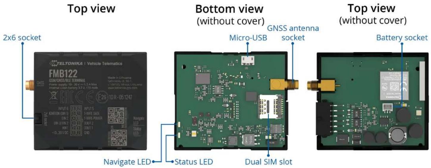
Figure 1 FMB122 device view
TELTONIKA
Pinout
Table 1 FMB122 2x6 socket pinout
| PIN NUMBER | PIN NAME | DESCRIPTION |
| 1 | VCC (10-30) V DC (+) | Power supply (+10-30 V DC). |
| 2 AIN 1 | Analog input, channel 1. Input range: 0-30 V DC. | |
| 3 AIN 2 / DIN 3 | Analog input, channel 2. Input range: 0-30 V DC / Digital input, channel 3. | |
| 4 DIN 2 Digital input, channel 2. | ||
| 5 DIN 1 Digital input, channel 1. | ||
| 6 INPUT 6 TX EXT (LVCAN - TX). | ||
| 7 | GND (-) | Ground pin. (10-30) V DC (—) |
| 8 DOUT 1 | Digital output, channel 1. Open collector output. Max. 0,5 A DC | |
| 9 DOUT 2 | Digital output, channel 1. Open collector output. Max. 0,5 A DC | |
| 10 | 1WIRE POWER | +3,8 V output for 1-Wire devices. |
| 11 | 1WIRE DATA | Data for 1-Wire devices. |
| 12 | INPUT 5 | RX EXT (LVCAN - RX). |
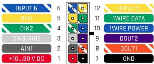
Figure 2 FMB122 2x6 socket pinout
TELTONIKA
Wiring scheme
flowchart
graph TD
    A["STARTER"] --> B["FUEL GAUGE"]
    B --> C["ALARM BUTTON"]
    C --> D["IGNITION DETECTION"]
    D --> E["RELAY 87a 86 30"]
    E --> F["ANALOG LLS SENSOR"]
    F --> G["POWER SUPPLY 10 - 30V DC"]
    G --> H["MULTIPLE TEMPERATURE SENSORS"]
    H --> I["IBUTTON"]
    I --> J["ALL-CAN300 LV-CAN200 CAN-CONTROL"]
    J --> K["INPUT 6 DIN1 DIN2 DIN3/AIN2 AIN1 +10...30 V DC"]
    K --> L["12 INPUT 5 11 10 9 8 7"]
    L --> M["1WIRE DATA 1WIRE POWER DOUT2 DOUT1 GND"]
    M --> N["BUZZER"]
    M --> O["LED LIGHTS"]
    N --> P["MULTIPLE TEMPERATURE SENSORS"]
    O --> Q["IBUTTON"]
    style A fill:#f9f,stroke:#333
    style B fill:#ccf,stroke:#333
    style C fill:#cfc,stroke:#333
    style D fill:#fcc,stroke:#333
    style E fill:#ffc,stroke:#333
    style F fill:#cfc,stroke:#333
    style G fill:#fcc,stroke:#333
    style H fill:#cfc,stroke:#333
    style I fill:#fcc,stroke:#333
    style J fill:#cfc,stroke:#333
    style K fill:#cfc,stroke:#333
    style L fill:#cfc,stroke:#333
    style M fill:#cfc,stroke:#333
    style N fill:#fcc,stroke:#333
    style O fill:#fcc,stroke:#333
    style P fill:#fcc,stroke:#333
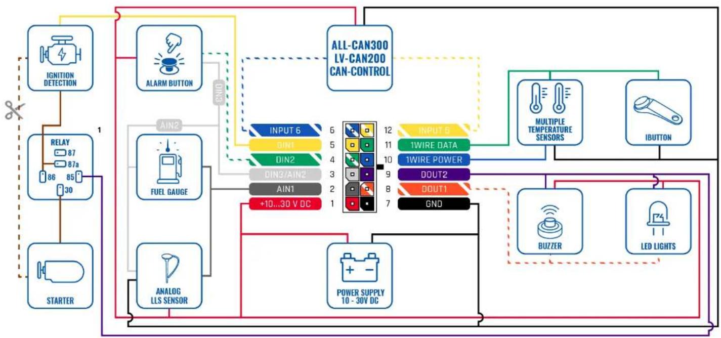
Figure 3 FMB122 Wiring scheme
TELTONIKA
Set up your device
How to insert SIM card and connect the battery
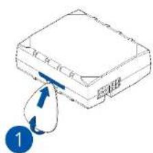
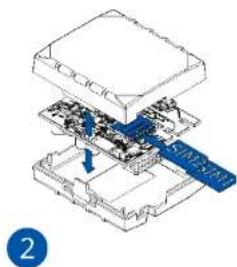
- Gently remove FMB122 cover using plastic pry tool from both sides.
- Insert SIM card as shown with PIN request disabled or read our Wiki how to enter it later in Teltonka Configurator. Make sure that SIM card cut-off corner is pointing outward from slot. SIM slot 1 is closer to PCB, SIM slot 2 is the top one.
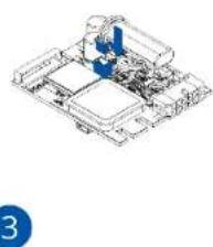
- Connect battery as shown to device. Position the battery in place where it does not obstruct other components.
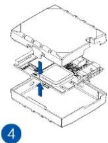
- After configuration, see "PC Connection (Windows)", attach device cover back.
natural_image
Diagram of a device with a blue arrow pointing to a component, labeled with number 1 (no text or symbols on the diagram itself)Figure 4 Cover removal
natural_image
Isometric diagram of a device's internal components with a blue arrow indicating a specific area (no text or symbols present)Figure 7 SIM card insert
natural_image
Isometric technical drawing of a mechanical assembly with no visible text or symbolsFigure 5 Battery connection
natural_image
Isometric technical diagram of a layered mechanical assembly with no visible text or symbolsFigure 6 Attaching cover back
TELTONIKA
PC Connection (Windows)
- Power-up FMB122 with DC voltage (10 - 30 V) power supply using supplied power cable. LED's should start blinking, see "LED indications".
- Connect device to computer using Micro-USB cable or Bluetooth connection:
• Using Micro-USB cable
- You will need to install USB drivers, see "How to install USB drivers (Windows)"
• Using Bluetooth
- FMB122 Bluetooth is enabled by default. Turn on Bluetooth on your PC, then select Add Bluetooth or other device > Bluetooth. Choose your device named - "FMBxxx_last_7_imei_digits", without LE in the end. Enter default password 5555, press Connect and then select Done.
- You are now ready to use the device on your computer.
How to install USB drivers (Windows)
- Please download COM port drivers from here.
- Extract and run TeltonikaCOMDriver.exe.
- Click Next in driver installation window.
- In the following window click Install button.
Setup will continue installing the driver and eventually the confirmation window will appear. Click Finish to complete the setup.
Configuration (Windows)
At first FMB122 device will have default factory settings set. These settings should be changed according to the user's needs. Main configuration can be performed via Teltonika Configurator software. Get the latest Configurator version from here. Configurator operates on Microsoft Windows OS and uses prerequisite MS .NET Framework. Make sure you have the correct version installed.
Table 2 MS .NET requirements
| MS .NET REQUIREMENTS | |||
| Operating system | MS .NET Framework version | Version Links | |
| Windows Vista Windows 7 Windows 8.1 Windows 10 | MS .NET Framework 4.6.2 | 32 and 64 bit | www.microsoft.com |
Downloaded Configurator will be in compressed archive. Extract it and launch Configurator.exe. After launch software language can be changed by clicking 📄 in the right bottom corner (Figure 8 Language selection).
TELTONIKA
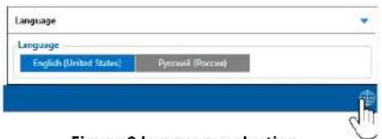
Figure 8 Language selection
Configuration process begins by pressing on connected device (Figure 9 Device connected via USB).
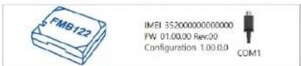
Figure 9 Device connected via USB
After connection to Configurator Status window will be displayed (Figure 10 Configurator Status window).
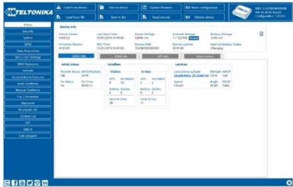
Figure 10 Configurator Status window
Various Status window tabs display information about GNSS, GSM, I/O, Maintenance and etc. FMB122 has one user editable profile, which can be loaded and saved to the device. After any modification of configuration the changes need to be saved to device using Save to device button. Main buttons offer following functionality:
- Load from device – loads configuration from device.
- Save to device – saves configuration to device.
- Load from file - loads configuration from file.
- Save to file - saves configuration to file.
- Update firmware – updates firmware on device.
- Read records – reads records from the device.
- Reboot device – restarts device.
- Reset configuration – sets device configuration to default.
Most important configurator section is GPRS – where all your server and GPRS settings can be configured and Data Acquisition – where data acquiring parameters can be configured.
More details about FMB122 configuration using Configurator can be found in our Wiki.
TELTONIKA
Quick SMS configuration
Default configuration has optimal parameters present to ensure best performance of track quality and data usage.
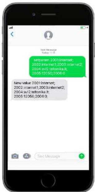
Quickly set up your device by sending this SMS command to it:
" setparam 2001:APN;2002:APN_username;2003:APN_password;2004:Domain;2005:Port;2006:0"
Note: Before SMS text, two space symbols should be inserted.
GPRS settings:
• 2001 - APN
• 2002 – APN username (if there are no APN username, empty field should be left)
• 2003 – APN password (if there are no APN password, empty field should be left)
Server settings:
• 2004 - Domain
• 2005 - Port
• 2006 – Data sending protocol (0 – TCP, 1 – UDP)
Default configuration settings
Movement and ignition detection:

Vehicle movement will be detected by accelerometer

Ignition will be detected by vehicle power voltage between 13,2 - 30 V
Device makes a record On Moving if one of these events happen:

300 seconds passes

Vehicle turns 10 degrees

Vehicle drives 100 meters

Speed difference between last coordinate and current position is greater than 10 km/h
Device makes a record On Stop if:

1 hour passes while vehicle is stationary and ignition is off
Records sending to server:

If device has made a record it is sent to the server every 120 seconds
After successful SMS configuration, FMB122 device will synchronize time and update records to configured server. Time intervals and default I/O elements can be changed by using Teltonika Configurator or SMS parameters.
TELTONIKA
Mounting recommendations
- Connecting wires
- Wires should be connected while the module is not plugged in.
- Wires should be fastened to stable wires or other non-moving parts. Any heat emitting and/or moving objects should be kept away from the wires.
- There should be no exposed wires. If factory isolation was removed while connecting the wires, the isolation material should be applied.
- If the wires are placed in the exterior or in places where they can be damaged or exposed to heat, humidity, dirt, etc., additional isolation should be applied and the wires should not be loose.
- Wires cannot be connected to the board computers or control units.
- Connecting power source
- Be sure that after the car computer goes to sleep mode, power might be still available on the power wires.
Depending on the car model, this may happen in 5 to 30 minutes period.
- When the module is connected, measure the voltage again to make sure it did not decrease.
- It is recommended to connect to the main power cable in the fuse box.
- 3 A, 125 V external fuse shall be used.
- Connecting ignition wire
- Be sure to check if it is a real ignition wire i. e. power does not disappear after starting the engine.
- Check if this is not an ACC wire (when key is in the first position, most of the vehicle electronics are available).
- Check if power is still available when you turn off any of vehicles devices.
- Ignition is connected to the ignition relay output. As alternative, any other relay, which has power output when ignition is on, may be chosen.
- Connecting ground wire
- Ground wire is connected to the vehicle frame or metal parts that are fixed to the frame.
- If the wire is fixed with the bolt, the loop must be connected to the end of the wire.
- For better contact scrub paint from the spot where loop is going to be connected.
TELTONIKA
LED indications
Table 3 Navigation LED indications
| BEHAVIOUR MEANING | |
| Permanently switched on GNSS signal is not received | |
| Blinking every second | Normal mode, GNSS is working |
| Off | GNSS is turned off because:Device is not working or Device is in sleep mode |
| Blinking fast constantly | Device firmware is being flashed |
Table 4 Status LED indications
| BEHAVIOUR MEANING | |
| Blinking every second Normal mode | |
| Blinking every two seconds Sleep mode | |
| Blinking fast for a short time Modem activity | |
| Off | Device is not working or Device is in boot mode |
Characteristics
Basic characteristics
Table 5 Basic characteristics
| MODULE | |
| Name Teltonika TM2500 | |
| Technology | GSM/GPRS/GNSS/BLUETOOTH |
| GNSS | |
| GNSS | GPS, GLONASS, GALILEO, BEIDOU, SBAS, QZSS, DGPS, AGPS |
| Receiver 33 channel | |
| Tracking sensitivity -165 dBM | |
| Accuracy < 3 m | |
| Hot start < 1 s | |
| Warm start < 25 s | |
| Cold start < 35 s | |
| CELLULAR | |
| Technology GSM | |
| 2G bands | Quad-band 850 / 900 / 1800 / 1900 MHz |
| Data transfer | GPRS Multi-Slot Class 12 (up to 240 kbps), GPRS Mobile Station Class B |
| Data support | SMS (text/data) |
TELTONIKA
POWER
| Input voltage range | 10-30 V DC with overvoltage protection |
| Back-up battery | 170 mAh Li-Ion battery 3.7 V (0.63 Wh) |
| Internal fuse 3 A, 125 V | |
| Power consumption | At 12V < 6 mA (Ultra Deep Sleep)At 12V < 8 mA (Deep Sleep)At 12V < 11 mA (Online Deep Sleep)At 12V < 19 mA (GPS Sleep)At 12V < 34 mA (nominal no load)At 12V < 1.5 A Max. (with full Load/Peak) |
BLUETOOTH
| Specification | 4.0 + LETemperature and Humidity sensor,Headset, OBDII dongle, Inateck BarcodeScanner, Universal BLE sensors support |
| Supported peripherals |
INTERFACE
| Digital Inputs 3 | |
| Digital Outputs | 2 |
| Analog Inputs | 2 |
| CAN Adapter inputs | 1 |
| 1-Wire | 1 |
| GNSS antenna | External (MMCX connector) |
| GSM antenna | Internal High Gain |
| USB | 2.0 Micro-USB |
| LED indication 2 status LED lights | |
| SIM | Dual SIM |
| Memory 128MB internal flash memory | |
PHYSICAL SPECIFICATION
| Dimensions | 65 x 56,6 x 20,6 mm (L x W x H) |
| Weight | 55 g |
OPERATING ENVIRONMENT
| Operating temperature (without battery) | -40 °C to +85 °C |
| Storage temperature (without battery) | -40 °C to +85 °C |
| Operating humidity | 5% to 95% non-condensing |
| Ingress Protection Rating | IP41 |
| Battery charge temperature | 0 °C to +45 °C |
| Battery discharge temperature | -20 °C to +60 °C |
| Battery storage temperature | -20 °C to +45 °C for 1 month-20 °C to +35 °C for 6 months |
FEATURES
| Sensors | AccelerometerGreen Driving, Over Speeding detection,Jamming detection, GNSS Fuel Counter,DOUT Control Via Call, Excessive Idling detection, Immobilizer, iButton Read Notification, Unplug detection, Towing detection, Crash detection, Auto Geofence, Manual Geofence, Trip |
| Scenarios | |
| Sleep modes | GPS Sleep, Online Deep Sleep, Deep Sleep, Ultra Deep SleepFOTA Web, FOTA, Teltonika Configurator (USB, Bluetooth), FMBT mobile application (Configuration) |
| Configuration and firmware update | |
| SMS | Configuration, Events, DOUT control, Debug |
| GPRS commands | Configuration, DOUT control, Debug |
| Time Synchronization | GPS, NITZ, NTP |
| Fuel monitoring | LLS (Analog), LV-CAN200, ALL-CAN300,OBDII dongle, CAN-CONTROL |
| Ignition detection | Digital Input 1, Accelerometer, External Power Voltage, Engine RPM (CAN Adapters, OBDII dongle) |
TELTONIKA
Electrical characteristics
Table 6 Electrical characteristics
| CHARACTERISTIC DESCRIPTION | VALUE | |||
| MIN. | TYP. | MAX. | UNIT | |
| SUPPLY VOLTAGE | ||||
| Supply Voltage (Recommended Operating Conditions) | +10 | +30 V | ||
| DIGITAL OUTPUT (OPEN DRAIN GRADE) | ||||
| Drain current (Digital Output OFF) | 120 | μA | ||
| Drain current (Digital Output ON, Recommended Operating Conditions) | 0.1 | 0.5 A | ||
| Static Drain-Source resistance (Digital Output ON) | 400 | 600 mΩ | ||
| DIGITAL INPUT | ||||
| Input resistance (DIN1) | 47 | kΩ | ||
| Input resistance (DIN2) | 51.7 | kΩ | ||
| Input resistance (DIN3) | 150 | kΩ | ||
| Input voltage (Recommended Operating Conditions) | 0 | Supply voltage | V | |
| Input Voltage threshold (DIN1) | 7.5 | V | ||
| Input Voltage threshold (DIN2) | 2.5 | V | ||
| Input Voltage threshold (DIN3) | 2.5 | V | ||
| ANALOG INPUT | ||||
| Input voltage (Recommended Operating Conditions), Range 1 | 0 | +10 | V | |
| Input resistance, Range 1 | 38.45 | kΩ | ||
| Measurement error on 12V, Range 1 | 0.9 | % | ||
| Additional error on 12 V, Range 1 | 108 | mV | ||
| Measurement error on 30 V, Range 1 | 0.33 | % | ||
| Additional error on 30 V, Range 1 | 88 | mV | ||
| Input Voltage (Recommended Operating Conditions), Range 2 | 0 | +30 | V | |
| Input resistance, Range 2 | 150 | kΩ | ||
| Measurement error on 12 V, Range 2 | 0.9 | % | ||
| Additional error on 12 V, Range 2 | 108 | mV | ||
| Measurement error on 30 V, Range 2 | 0.33 | % | ||
| Additional error on 30 V, Range 2 | 88 | mV | ||
| OUTPUT SUPPLY VOLTAGE 1-WIRE | ||||
| Supply voltage | +4.5 | +4.7 | V | |
| Output inner resistance | 7 | Ω | ||
| Output current ( U_out > 3.0 V) | 30 | mA | ||
| Short circuit current ( U_out = 0 ) | 75 | mA | ||
TELTONIKA
Safety information
This message contains information on how to operate FMB122 safely. By following these requirements and recommendations, you will avoid dangerous situations. You must read these instructions carefully and follow them strictly before operating the device!
- The device uses SELV limited power source. The nominal voltage is +12 V DC. The allowed voltage range is +10...+30 V DC.
- To avoid mechanical damage, it is advised to transport the device in an impact-proof package. Before usage, the device should be placed so that its LED indicators are visible. They show the status of device operation.
- When connecting the 2x6 connector wires to the vehicle, the appropriate jumpers of the vehicle power supply should be disconnected.
- Before unmounting the device from the vehicle, the 2x6 connector must be disconnected. The device is designed to be mounted in a zone of limited access, which is inaccessible to the operator. All related devices must meet the requirements of EN 62368-1 standard. The device FMB122 is not designed as a navigational device for boats.

Do not disassemble the device. If the device is damaged, the power supply cables are not isolated or the isolation is damaged, DO NOT touch the device before unplugging the power supply.

All wireless data transferring devices produce interference that may affect other devices which are placed nearby.
The device must be connected only by qualified personnel.
The device must be firmly fastened in a predefined location.
The programming must be performed using a PC with autonomic power supply.
Installation and/or handling during a lightning storm is prohibited.
The device is susceptible to water and humidity.
Risk of explosion if battery is replaced by an incorrect type. Dispose of used batteries according to the instructions.
Battery should not be disposed of with general household waste. Bring damaged or worn-out batteries to your local recycling center or dispose them to battery recycle bin found in stores.
TELTONIKA
Certification and Approvals
FMB122 EAC
FMB122 REACH
• FMB122 Declaration of IMEI assignment
• FMB122 CE / RED
FMB122 E-Mark
• FMB122 RoHS
• FMB122 Declaration of device operation temperature

This sign on the package means that it is necessary to read the User's Manual before your start using the device. Full User's Manual version can be found in our Wiki.

This sign on the package means that all used electronic and electric equipment should not be mixed with general household waste.

Hereby, Teltonika declare under our sole responsibility that the above described product is in conformity with the relevant Community harmonization: European Directive 2014/53/EU (RED).
TELTONIKA
Warranty
TELTONIKA guarantees its products to be free of any manufacturing defects for a period of 24 months. With additional agreement we can agree on a different warranty period, for more detailed information please contact our sales manager.
Contact us teltonika.lt/company/contacts
All batteries carry a reduced 6 month warranty period.
If a product should fail within this specific warranty time, the product can be:
- Repaired
- Replaced with a new product
- Replaced with an equivalent repaired product fulfilling the same functionality
- TELTONIKA can also repair products that are out of warranty at an agreed cost.
Warranty Disclaimer
TELTONIKA PRODUCTS ARE INTENDED TO BE USED BY PERSONS WITH TRAINING AND EXPERIENCE. ANY OTHER USE RENDERS THE LIMITED WARRANTIES EXPRESSED HEREIN AND ALL IMPLIED WARRANTIES NULL AND VOID AND SAME ARE HEREBY EXCLUDED. ALSO EXCLUDED FROM THIS LIMITED WARRANTY ARE ANY AND ALL INCIDENTAL OR CONSEQUENTIAL DAMAGES INCLUDING BUT NOT LIMITED TO, LOSS OF USE OR REVENUE, LOSS OF TIME, INCONVENIENCE OR ANY OTHER ECONOMIC LOSS.
More information can be found at teltonika.lt/warranty-repair
- Quick Manual v1.6
- TELTONIKA
- Table of Contents
- Know your device
- Pinout
- Set up your device
- How to insert SIM card and connect the battery
- PC Connection (Windows)
- How to install USB drivers (Windows)
- Configuration (Windows)
- Quick SMS configuration
- Default configuration settings
- Mounting recommendations
- - Connecting wires
- - Connecting power source
- - Connecting ignition wire
- - Connecting ground wire
- LED indications
- Characteristics
- Basic characteristics
- Electrical characteristics
- Safety information
- Certification and Approvals
- Warranty
- All batteries carry a reduced 6 month warranty period.
- Warranty Disclaimer
Brand : Teltonika
Model : FMB122
Category : Gps