
P3400 - Generator BRIGGS & STRATTON - Free user manual and instructions
Find the device manual for free P3400 BRIGGS & STRATTON in PDF.


| Product Type | Portable Inverter Generator |
| Brand | Briggs & Stratton |
| Model | P3400 |
| Rated Wattage | 2,800 W |
| Starting Wattage | 3,400 W |
| AC Output | 230 V, 12.2 A, 50 Hz, Single Phase |
| DC Output | 12 V, 5 A (60 W max) |
| USB Output | 5 V, 2.1 A (combined) |
| Engine Displacement | 171 cc |
| Fuel Type | Unleaded gasoline (min 91 RON, up to 10% ethanol) |
| Fuel Capacity | 4.0 L (1.0 US gal) |
| Oil Capacity | 0.4 L (13.5 oz) |
| Oil Type | SAE 30, 10W30, 5W30, or Vanguard 15W50 synthetic (depending on temperature) |
| Spark Plug Gap | 0.6 - 0.7 mm |
| Sound Pressure (at 7 m) | 78 dBA |
| Control Panel Features | Statstation LCD (load monitor, hour meter, maintenance reminder), QPT switch, circuit breakers, CO shutdown indicator, parallel operation port |
| Safety Features | Carbon monoxide shutdown system, low oil shutdown, overload protection, circuit breakers |
| Parallel Operation | Yes (with optional parallel kit; combined max 5100 W with two P3400) |
| Recoil Start | Manual recoil starter with choke |
| Maintenance Requirements | Oil change every 100 hours, air cleaner service every 50 hours, spark plug annually |
| Warranty | 36 months consumer use, 12 months commercial |
Frequently Asked Questions - P3400 BRIGGS & STRATTON
User questions about P3400 BRIGGS & STRATTON
0 question about this device. Answer the ones you know or ask your own.
Ask a new question about this device
Download the instructions for your Generator in PDF format for free! Find your manual P3400 - BRIGGS & STRATTON and take your electronic device back in hand. On this page are published all the documents necessary for the use of your device. P3400 by BRIGGS & STRATTON.
USER MANUAL P3400 BRIGGS & STRATTON
Outdoor Portable Generator
Operator's Manual
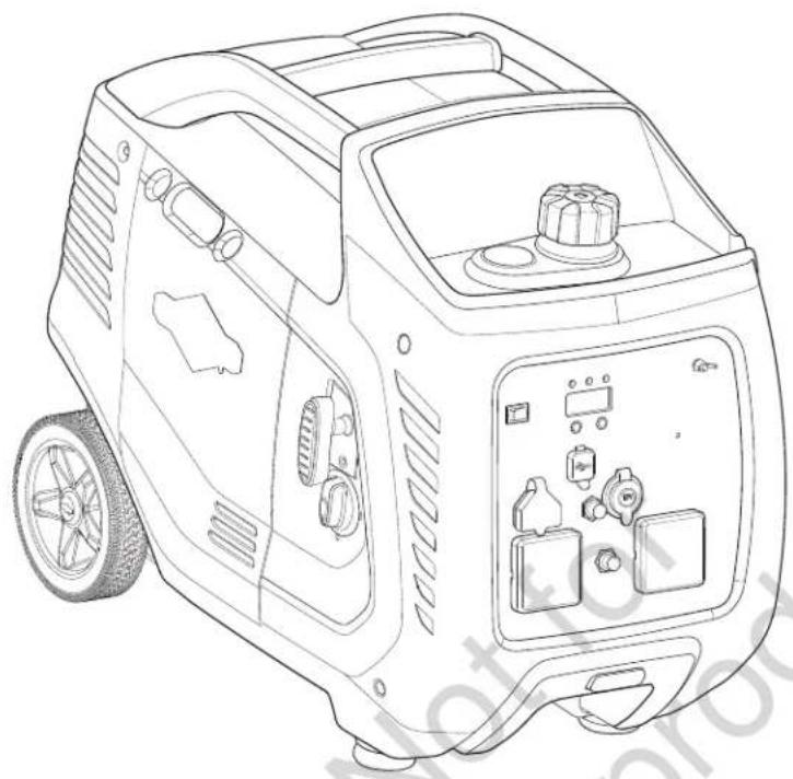
natural_image
Line drawing of a portable electricity generator with control panel and buttons (no text or symbols)
Model Number ____
Revision ____
Serial Number ____
Date Purchased ____
Copyright © 2020. Briggs & Stratton Corporation
Milwaukee, WI, USA. All rights reserved.
1800-356-632 (AUS) or 0800-484-282 (NZ)
BRIGGSandSTRATTON.com.au
Table of Contents
Equipment Description....2
Features and Controls .... 4
Operation....6
Maintenance....11
Storage 14
Troubleshooting/Specifications ..... 15
Warranty 16
Symbols and Meanings
| Signal Meaning | |
| DANGER | Indicates a hazard which, if not avoided, will result in death or serious injury. |
| WARNING | Indicates a hazard which, if not avoided, could result in death or serious injury. |
| CAUTION | Indicates a hazard which, if not avoided, could result in minor or moderate injury. |
| NOTICE | Indicates information considered important, but not hazard-related. |
| Symbol | Name Explanation | |
 | Safety Alert Symbol | Indicates a potential personal injury hazard. |
 | Operator's Manual | Failure to follow warnings, instructions and operator's manual could result in death or serious injury. |
 | Toxic Fumes | Engine exhaust contains carbon monoxide, a poisonous gas that could kill you in minutes. You cannot smell it or see it. |
 | Fire | Fuel and its vapors are extremely flammable which could cause burns or fire resulting in death or serious injury.Engine exhaust could cause fire resulting in death or serious injury. |
 | Electric Shock | Generator could cause electrical shock resulting in death or serious injury. |
 | Hot Surface | Muffler could cause burns or resulting in serious injury. |
Equipment Description

Read this manual carefully and become familiar with your outdoor generator. Know its applications, its limitations, and any hazards involved. Save these original instructions for future reference.
The outdoor generator is an engine-driven, revolving field, alternating and direct current (AC & DC) generator. It was designed to supply electrical power for operating compatible electrical lighting, appliances, tools and motor loads. The generator's revolving field is driven by a single-cylinder engine.
The portable generator can be used to power outdoor items using an extension cord or to restore home power using a transfer switch. A transfer switch is a separate device installed by a licensed electrician that allows the portable generator to be cord connected, using the receptacle, directly into your home's electrical system. Install a manual transfer switch as soon as possible if generator will be used to provide home power restoration.
The generator is not intended to supply systems that are legally required, for serious life safety or health hazards, or where lack of power hampers rescue of fire-fighting operations.
Every effort has been made to ensure that the information in this manual is both accurate and current. However, the manufacturer reserves the right to change, alter or otherwise improve the generator and this documentation at any time without prior notice.
NOTICE If you have questions about intended use, contact an authorized service dealer. This equipment is designed to be used with Briggs & Stratton® authorized parts only.
System Ground
The generator has a system ground that connects the generator frame components to the ground terminals on the AC output receptacles. The generator neutral is floating, which means that the AC stator winding is isolated from the grounding fastener and the AC receptacle ground pins. Electrical devices, such as RCD, requiring a grounded neutral may not operate properly from this generator. Earthing of the generator is not required.
Special Requirements
There may be regulations, local codes, or ordinances that apply to the intended use of the generator. Please consult a qualified electrician, electrical inspector, or the local agency having jurisdiction.
This generator is not intended to be used at a construction site.
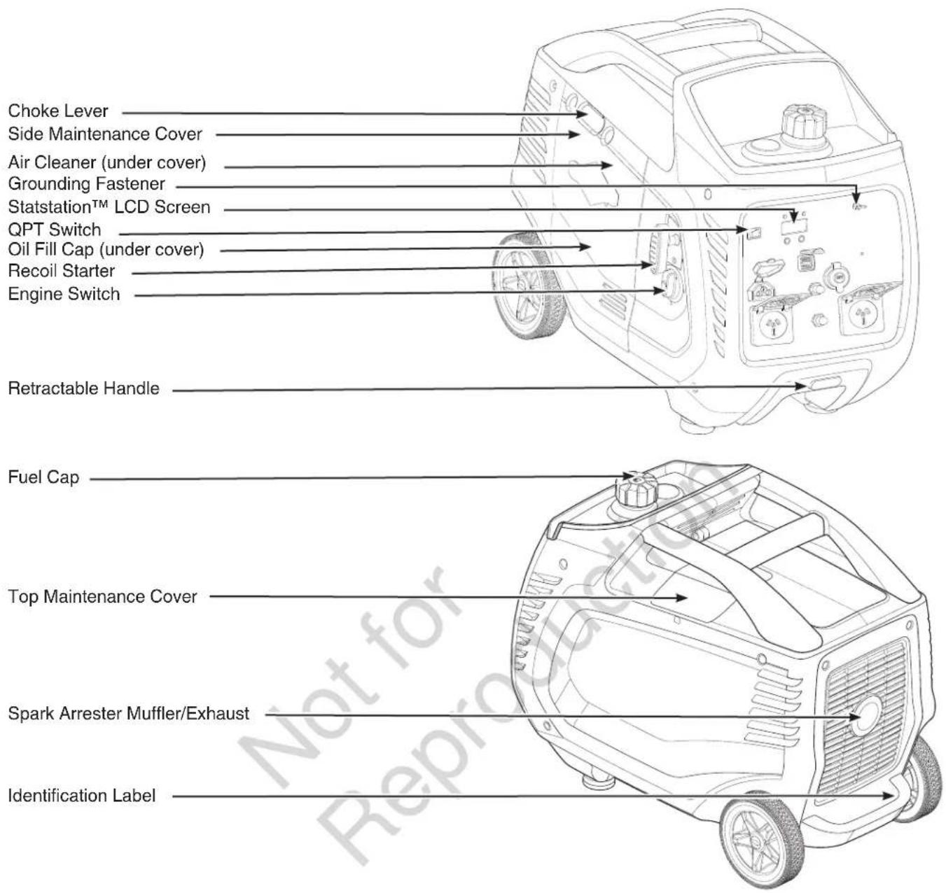
Air Cleaner — Filters engine intake air.
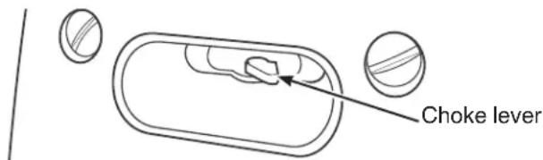
Choke Lever — Used when starting a cold engine.
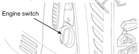
Engine Switch — Set this switch to ON (I) before using recoil starter. Set switch to OFF (0) to stop engine. Also turns fuel valve on and off.
Fuel Cap — Add unleaded fuel here.
Grounding Fastener — Consult your local agency having jurisdiction for grounding requirements in your area.
Identification Label — Provides model and serial number of generator.
Oil Fill Cap — Check, add and drain engine oil here.
QPT™ (QUIET POWER TECHNOLOGY™) Switch — Use this button to turn the QPT on and off.
Recoil Starter — Used to start the engine manually.
Retractable Handle — Press button and pull handle out to move generator. Press button to push handle back in.
Side Maintenance Cover — Remove to gain access to the air cleaner and oil service.
Spark Arrester Muffler/Exhaust — Lowers engine noise and is equipped with a spark arrester screen.
Statstation™ LCD Screen — Built in LCD screen to monitor certain features on the generator. See STATSTATION™.
Top Maintenance Cover — Remove to gain access to the spark plug.
Compare the illustrations with your generator to familiarize yourself with the locations of various controls and product warnings.
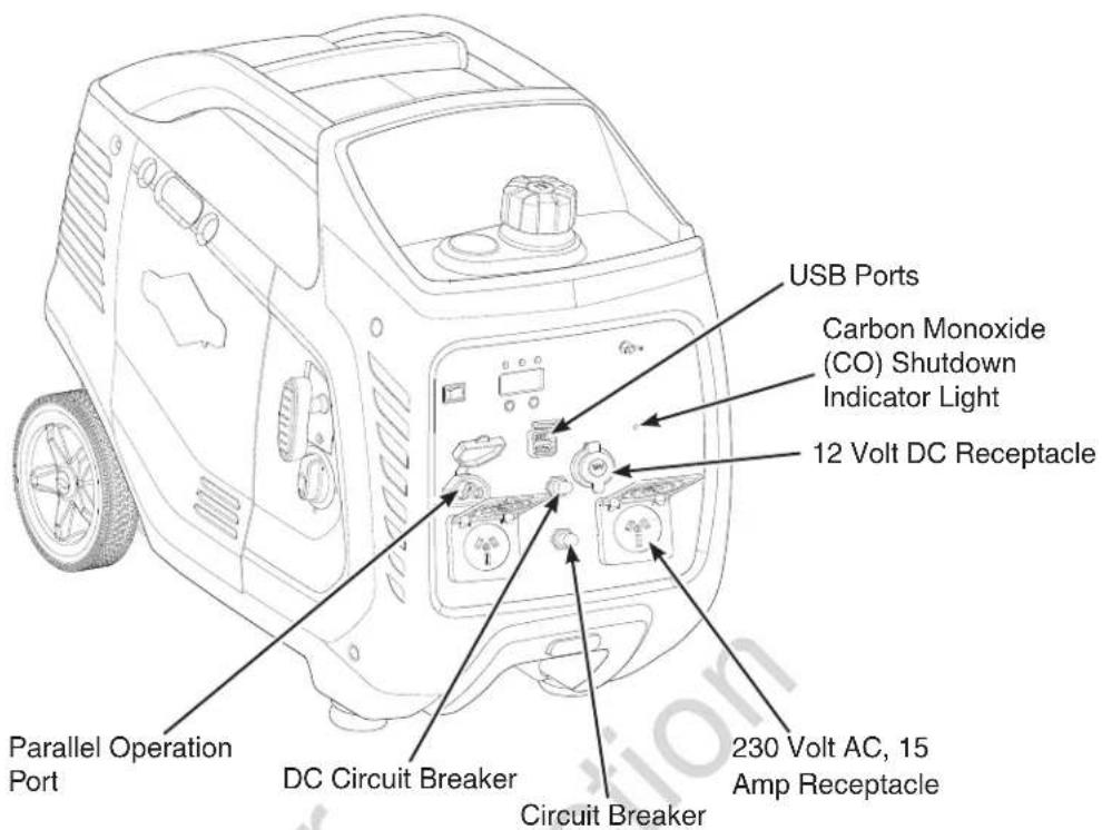
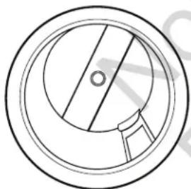
12 Volt DC Receptacle — Use this receptacle to supply power for 12 Volt DC accessories that are rated 60 watts (5 Amp) or less. This receptacle is protected by a push to reset circuit breaker.
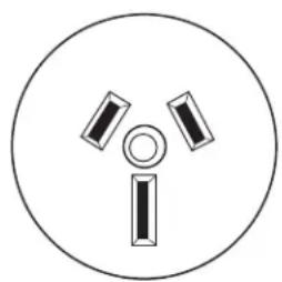
230 Volt AC, 15 Amp Receptacle — May be used to supply electrical power for the operation of 230 Volt AC, 15 Amp, single phase, 50 Hz electrical, lighting, appliance, tool, and motor loads.
Carbon Monoxide (CO) Shutdown Indicator Light — Indicates the engine shutdown due to carbon monoxide accumulation around the generator or a CO shutdown system fault occurred.
Circuit Breaker — A "push to reset" circuit breaker is provided to protect the generator against electrical overload.
DC Circuit Breaker — The 12 Volt DC receptacle is provided with a "push to reset" circuit breaker to protect the generator against electrical overload.
Parallel Operation Port — Use this port with optional parallel operation kit to connect and combine the output of two generators.
USB Ports — Use ports to recharge most USB powered devices.
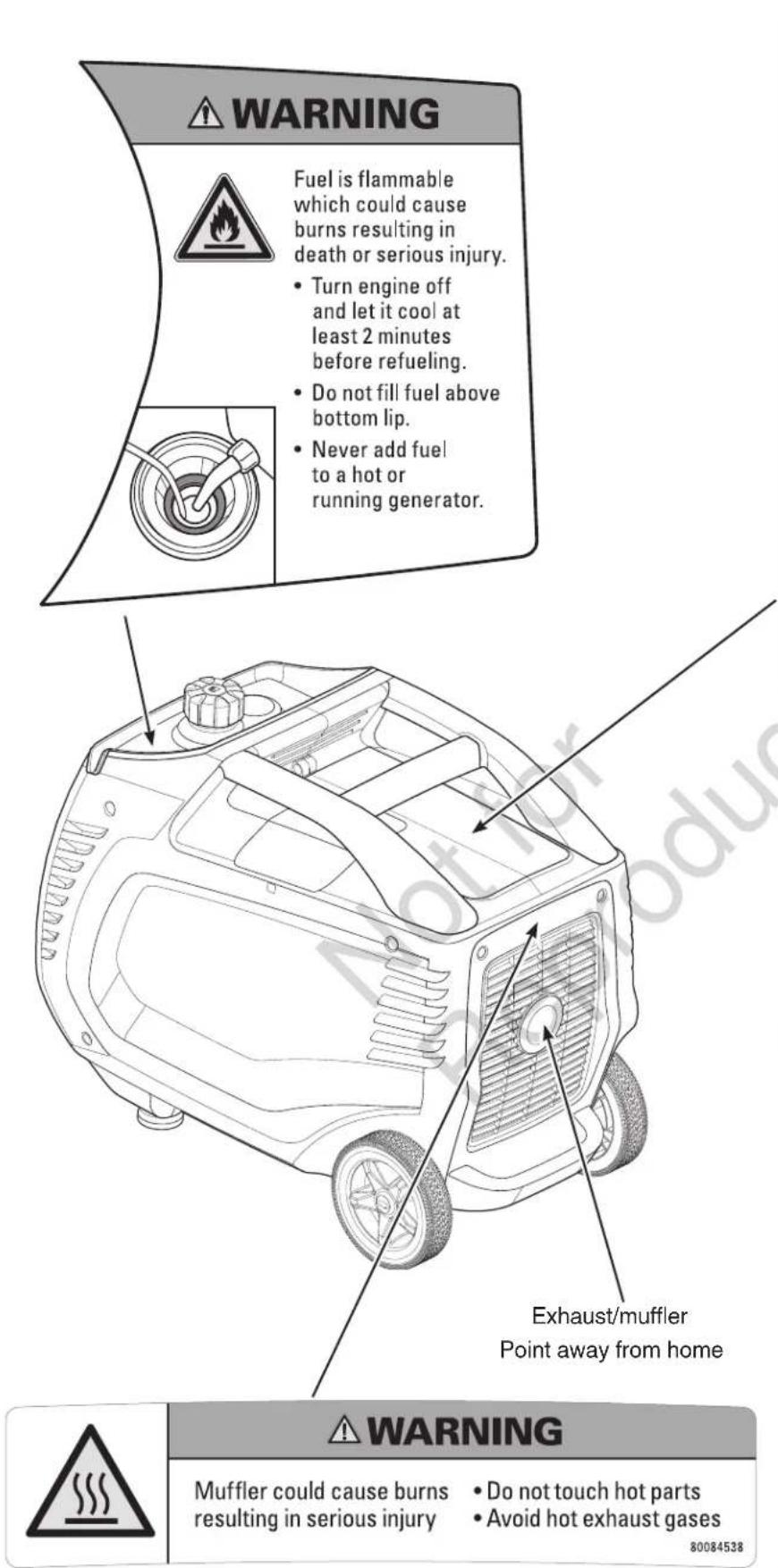
 | Point engine exhaust away from all homes |  |
| WARNING | ||
 | Failure to follow warnings, instructions and operator's manual could result in death or serious injury. | |
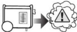
 | Engine exhaust contains carbon monoxide, a poisonous gas that could kill you in minutes.You CANNOT smell it, see it, or taste it.Operate this product ONLY outside, at least 6.1 m away from windows, doors, and vents.Tampering with the CO Shutoff System could cause Carbon Monoxide poisoning. Install Carbon Monoxide alarms inside home. | |
 | Generator could cause electrical shock.Do not run indoors to avoid wet conditions.Do not run in rain or wet weather.The output of this generating set is potentially lethal. The set shall not be connected to a fixed electrical installation by fixed wiring except by an appropriately licensed person. | |
 | Hot exhaust gases could cause fires.Keep at least 1.5m clearance from any combustibles or structures, including overhead. | |
 | AUTOMATIC SHUTOFF - YOU MUST: | |
| Move generator to an open, outdoor area. Point exhaust away from homes. Don't run generator in enclosed areas (e.g. not in house or garage). Air out premises (e.g. open windows and doors) before reoccupying. | ||
 | (6.1 m) MIN. | |
 |  | |
 | [6KSH] | Move to fresh air and get medical help if sick, dizzy or weak.80084449 |
Operation
Step 1: Safe Location
Before starting the portable generator there are two equally important safety concerns regarding carbon monoxide poisoning and fire that must be addressed.
Operation Location to Reduce the Risk of Carbon Monoxide Poisoning
The engine exhaust of all fossil fuel burning equipment, such as a portable generator, contains carbon monoxide, a poisonous gas that could kill you in minutes. You cannot smell it, see it, or taste it. Even if you do not smell exhaust fumes, you could still be exposed to carbon monoxide gas.
By law it is required in many states to have a carbon monoxide alarm in operating condition in your home. A carbon monoxide alarm is an electronic device that detects hazardous levels of carbon monoxide. When there is a buildup of carbon monoxide, the alarm will alert the occupants by flashing visual indicator light and alarm. Smoke alarms cannot detect carbon monoxide gas.
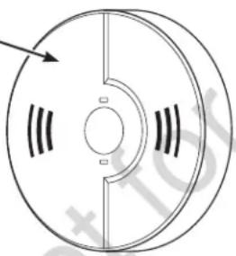
Carbon Monoxide Alarm(s).
Install carbon monoxide alarm inside your home. Without working carbon monoxide alarms, you will not realize you are getting sick and dying from carbon monoxide poisoning.
natural_image
Technical line drawing of a circular mechanical component with internal slots and a central hub (no text or symbols)
WARNING! Engine exhaust contains carbon monoxide, a poisonous gas that could kill you in minutes. You cannot smell it, see it, or taste it.
Even if you do not smell exhaust fumes, you could still be exposed to carbon monoxide gas.
- Operate portable generator only outdoors, at least 6.1 m (20 ft.) from occupied spaces with exhaust pointed away to reduce the risk of carbon monoxide accumulating.
- Install battery-operated carbon monoxide alarms or plug-in carbon monoxide alarms with battery back-up according to the manufacturer's instructions. Smoke alarms cannot detect carbon monoxide gas.
- Do not run portable generator inside homes, garages, basements, crawlspaces, sheds, or other partially-enclosed spaces even if using fans or opening doors and windows for ventilation. Carbon monoxide can quickly build up in these spaces and can linger for hours, even after this product has shut off.
If you start to feel sick, dizzy, weak, or your homes carbon monoxide alarm sounds while using this product, get to fresh air right away. Call emergency services. You may have carbon monoxide poisoning.
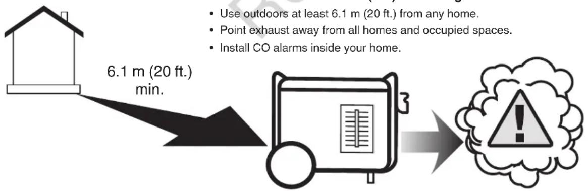
Prevent Carbon Monoxide (CO) Poisoning
- Use outdoors at least 6.1 m (20 ft.) from any home.
- Point exhaust away from all homes and occupied spaces.
• Install CO alarms inside your home.
flowchart
graph LR
    A["House at 6.1 m (20 ft.) min."] --> B["Firebox with warning label"]
    B --> C["Warning: Use outdoors at least 6.1 m (20 ft.) from any home.<br>Point exhaust away from all homes and occupied spaces.<br>Install CO alarms inside your home."]
To better educate yourself about all carbon monoxide risks, go to www.takeyourgeneratoroutside.com.
Operation Location to Reduce the Risk of Fire

WARNING! Exhaust heat/gases could ignite combustibles, structures or damage fuel tank causing a fire, resulting in death or serious injury.
- Portable generator must be at least 1.5 m (5 ft.) from any structure, overhang, trees, shrubs, or vegetation over 30.5 cm (12 in.) in height.
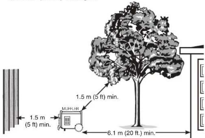
- Do not place portable generator under a deck or other type of structure that may confine airflow. Smoke alarm(s) must be installed and maintained indoors according to the manufacturer's instructions/recommendations.
• Carbon monoxide alarms cannot detect smoke. - Do not place portable generator in manner other than shown.
Step 2: Oil and Fuel
- Move generator outdoors to a flat, level surface.
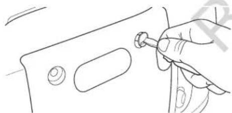
- Loosen the two maintenance cover screws and remove the side maintenance cover.
natural_image
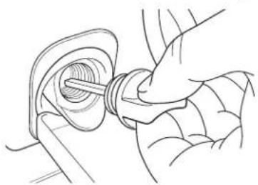
Line drawing of a hand holding a small tool with a knob, next to a metal bracket (no text or symbols)- Clean area around oil fill and remove yellow oil fill cap.
natural_image
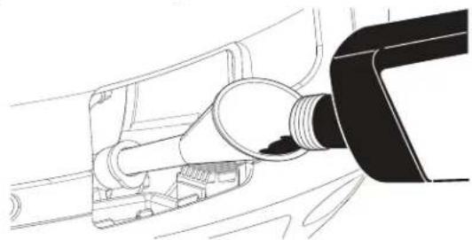
Line drawing of a hand inserting a plug into a mechanical component (no text or symbols)- Using an oil funnel, slowly pour contents of oil bottle into oil fill opening. Checking oil level frequently, fill to point of overflowing.
natural_image
Line drawing of a fuel nozzle connecting a car's side panel (no text or symbols)NOTICE Pause to permit oil to settle. DO NOT overfill.
- Replace and fully tighten oil fill cap.
- Replace the side maintenance cover and hand tighten the two maintenance cover screws.
Low Oil Indicator

The low oil indicator system is designed to prevent engine damage caused by not enough engine oil. If the engine oil level drops below a preset level, the yellow LED low oil indicator light comes on and an oil switch will stop the engine. If the engine stops or the yellow LED low oil indicator light comes on when you pull the recoil handle, check the engine oil level.
Fuel must meet these requirements:
- Clean, fresh, unleaded fuel with a minimum of 91 RON (87 octane/87 AKI).
• Gasoline with an ethanol content up to 10% is acceptable.
E10 E15
NOTICE Do not mix oil in fuel or modify engine to run on alternate fuels. Use of unapproved fuels could damage engine and will not be covered under warranty.
See High Altitude for 1524 m (5,000 ft.) and above.

WARNING! Fuel and its vapors are extremely flammable which could cause burns or fire resulting in death or serious injury.
- Do not refuel during operation.
- Do not smoke during refueling.
- Turn engine off and let it cool at least 2 minutes before removing fuel cap.
- Fill fuel tank outdoors. Keep fuel away from sparks, open flames, pilot lights, heat, and other ignition sources. Check fuel lines, tank, cap and fittings frequently for cracks or leaks. Replace if necessary.
-
Slowly remove fuel cap to relieve pressure in tank.
-
Slowly add unleaded fuel to red fuel level indicator in fuel tank. Be careful not to fill above the indicator. This allows adequate space for fuel expansion.
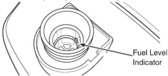
- Install fuel cap and let any spilled fuel evaporate before starting engine.
High Altitude
At altitudes over 1524 m (5,000 ft.), a minimum 89 RON (85 octane/85 AKI) fuel is acceptable. To remain emissions compliant, high altitude adjustment is required. Operation without this adjustment will cause decreased performance, increased fuel consumption, and increased emissions.
See an authorized Briggs & Stratton dealer for high altitude adjustment information. Operation of the engine at altitudes below 762 m (2,500 ft.) with the high altitude kit is not recommended.
Transporting
When transporting equipment, turn engine switch to off position. Do not tip engine or equipment at an angle which causes fuel to spill.
Step 3: Generator Start Up
Turn off all electrical loads connected to the generator. Use the following start instructions:
- Make sure unit is outdoors on a level surface.
NOTICE Failure to operate the unit on a level surface may cause the unit to shut down.
- Turn the engine switch to the ON (I) position.
- Push choke lever to CHOKE (I) position.
-
Grasp recoil handle and pull slowly until slight resistance is felt. Then pull rapidly to start engine.
-
If engine starts, proceed to step 6.
- If engine fails to start, proceed to step 5.

WARNING! Starter cord kickback (rapid retraction) will pull hand and arm toward engine faster than you can let go which could cause broken bones,
fractures, bruises, or sprains resulting in serious injury.
- When starting engine, pull cord slowly until resistance is felt and then pull rapidly to avoid kickback.
-
NEVER start or stop engine with electrical devices plugged in and turned on.
-
Move choke lever to half choke position, and pull recoil handle twice.
- If engine fails to start, repeat steps 3 thru 4.
- Slowly move choke lever to RUN (1) position. If engine falters, move choke lever to half choke position until engine runs smoothly, and then to RUN (1) position.
NOTICE If engine floods, move choke lever to RUN (1) position and crank until engine starts.
NOTICE If engine starts after 2 pulls but fails to run, or if unit shuts down during operation, make sure unit is on a level surface and check for proper oil level in crankcase. This unit is equipped with a low oil protection device. If so, oil must be at proper level for engine to start.
Step 4: Connecting Electrical Loads
To Restore Home Power Using a Transfer Switch
Connections to your home's electrical system must use a manual transfer switch installed by a qualified electrician. The connection must isolate the generator power from the utility power and comply with all applicable laws and electrical codes.
To Restore Power Using Extension Cords
Generator may only be loaded up to rated power under the rated conditions as shown on unit data tag. Reduce load when using generator outside of rated conditions.
Use only high quality, well-insulated extension cables in accordance with IEC 60245-4 with the generator's 230 Volt AC outlets. Inspect extension cables before each use. Check that all extension cables are suitably rated and are not damaged. When using extension cords under 40^ , the total length of cords for a cross section of 1.5mm^2 should not exceed 60m or for a cross section of 2.5mm^2 should not exceed 100m .

WARNING! Damaged or overloaded extension cords could overheat, arc, and burn resulting in death or serious injury.
- Electrical equipment, including cables and plug connections, should not be defective.
- Install carbon monoxide alarm(s).
- When operating generator with extension cords, make sure it is located in an open, outdoor area, at least 6.1 m from occupied spaces with exhaust pointed away.
- Extension cords running directly into home, powering indoor items IS NOT RECOMMENDED.

WARNING! Engine exhaust contains carbon monoxide, a poisonous gas that could kill you in minutes. You cannot smell it, see it, or taste it.
Even if you do not smell exhaust fumes, you could still be exposed to carbon monoxide gas.
- Extension cords running directly into the home increase your risk of carbon monoxide poisoning through openings.
- If an extension cord running directly into the home is used to power indoor items, the operator recognizes that this increases the risk of CO poisoning to people inside the home and assumes that risk.
- Install a manual transfer switch as soon as possible if generator will be used to provide home power restoration.
5 Volt DC USB Ports
The combined maximum current available for the USB ports is 2.1 Amps at 5 Volts. The USB port allows you to recharge most USB powered devices with a USB charging cable (not included).
NOTICE For maximum output, use the bottom USB port.
NOTICE For charging ITE (Information Technology Equipment) only.
12 Volt DC Receptacle
The maximum current available for the 12 Volt DC receptacle is 5 Amps. A DC circuit breaker protects this receptacle from overloads. If an overload occurs, the circuit breaker will trip (push button pops out). Wait a few minutes and push the button in to reset the circuit breaker.
natural_image
Simple line drawing of a circular mechanical component with a central hole and a side slot (no text or symbols)230 Volt AC, 15 Amp Receptacles
These receptacles are protected against overload by an internal overload system.
Use receptacles to operate 230 Volt AC, single-phase, 50 Hz electrical loads requiring up to 2,800 watts (2.8 kW) at 12.2 Amps of current. Use cord sets that are rated for 230 Volt AC loads at 15 Amps (or greater).
natural_image
Simple circular diagram with three vertical bars and a central circle, no text or symbols present.Output Indicator OK!
The green LED output indicator light comes on when the generator is operating normally. It indicates that the generator is producing power at the receptacles.
Overload Alarm
The red LED overload alarm light comes on and cuts power to the receptacles if you overload the generator. The green output indicator light will also go off. If the generator was overloaded, you must turn off and unplug all electrical loads, press the "Reset" button on the generator control panel and then plug in and restart electrical loads one at a time to continue in normal operating mode.
Parallel Operation
Two Briggs & Stratton inverter generators can be run in parallel with a Briggs & Stratton parallel operation kit (optional equipment). When running in parallel, the total output of power is shown in chart.
| Models Maximum Output |
| P2400 & P2400 3300 Watts |
| P2400 & P3400 4200 Watts |
| P3400 & P3400 5100 Watts |
NOTICE Total electrical load connected to the parallel kit must not exceed the maximum output.
See the parallel operation kits instruction sheet for detailed instructions on installation and operation of the connected generators.
NOTICE
- Turn electrical loads OFF and disconnect from both generators.
- The QPT switch must be in the same position on both generators.
- Connect the parallel cables to both generators before starting the engines. See instruction sheet supplied with parallel kit.
- Start engine on one of the inverter generators according to Generator Start Up.
- Once the green LED output indicator light on the first generators is steady, start second generator.
- Connect and turn on electrical loads to the parallel panel receptacles.
- DO NOT disconnect parallel cables after engines have been started.
- Shut down engines as described in Generator Shutdown.
QPT (QUIET POWER TECHNOLOGY)
This feature is designed to greatly improve fuel economy. When QPT is on, engine speed increases as loads are connected, and decreases as loads are removed.
When QPT is off, engine will run at full governed speed.
STATSTATION™
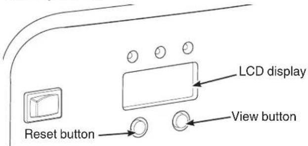
The control panel has a built in LCD display to monitor the following features:
- Load Monitor (Total Generator Load)
• Hour Meter (Total Generator Hours) - Maintenance Reminder (Engine Maintenance)
Load Monitor
The load monitor measures the output wattage (generator load) of all the generator receptacles and will display the percentage of total generator load.
Hour Meter
The LCD on the control panel also has a built in hour meter that displays and records how many hours your generator has run (up to 999.9).
Maintenance Reminder
The LCD on the control panel also has a built in maintenance reminder to alert you to change air filter, change oil, and change spark plug. The LCD display will flash both the load percentage and the hour display every 50 hours for the different maintenance intervals. See Maintenance Schedule for different maintenance intervals. Pressing the "View" button will toggle between the flashing load percentage and the flashing hour display. Once maintenance has been performed, you must push and hold the "View" button on the control panel for a minimum of 3 seconds to stop the display from flashing and return it to normal operation.
Generator Capacity
To make sure your generator can supply enough running watts and starting watts for the items you will power at the same time, follow these three simple steps:
- Select the items you will power at the same time. See following list for typical wattages.
| Tool or Appliance | Running Watts* | Starting Watts** |
| Light Bulb - 75 Watt | 75 | - |
| Refrigerator/Freezer | 550 | 1350 |
| Window AC - 10,000 BTU | 1000 | 2100 |
| Microwave Oven - 1000 Watt | 1000 | - |
| Plasma Television - 50” | 500 | - |
| Laptop | 250 | - |
* Typical wattages listed are approximate only. Check tool or appliance for actual wattage.
** The momentary electrical current the generator can provide to start electric motors, per Briggs & Stratton standard 628K. It does not represent the power required to continuously run electrical loads. It is the maximum current that can momentarily be supplied when starting a motor, multiplied by the generator's rated voltage.
- Total the running watts. This is the amount of power your generator must produce to keep your items running. See following example:
Example
Tool or Appliance Running Watts Starting Watts
| Window AC - 10000 BTU | 1000 | 2100 |
| Refrigerator/Freezer | 550 | 1350 |
| Plasma Television | 500 | — |
| Light (75 Watts) | 75 | — |
| 2125 Total Running Watts | 2100 Highest Starting Watts |
Total running watts = 2125
Highest starting watts = 2100
Total generator watts required = 4225
- Estimate the starting watts you will need. Because not all motors start at the same time, total starting wattage can be estimated by adding only the item with the highest additional starting watts requirements to the total running watts from step 2.
Power Management
To manage generator power, sequentially add loads as follows:
- With nothing connected to generator, start the engine outdoors.
- Plug in and turn on the first load, preferably the largest load you have.
- Permit the generator output to stabilize (engine runs smoothly and attached device operates properly).
- Plug in and turn on the next load.
- Again, permit the generator to stabilize.
- Repeat steps 4 and 5 for each additional load.
Never add more loads than the generator capacity. Take special care to consider starting watts in generator capacity.
Carbon Monoxide (CO) Shutdown System
Automatically shuts down the engine when harmful levels of carbon monoxide accumulate around the generator or a CO shutdown system fault occurs. After shutdown, the indicator light will blink for at least five minutes per the chart below.
The CO shutdown system DOES NOT replace carbon monoxide alarms. Install battery-powered carbon monoxide alarm(s) in your home. Do not run generator in enclosed areas.
| Color/Pattern | Description |
Red .. ..  | Carbon monoxide accumulated around generator. Move generator to an open, outdoor area 6.1 m (20 ft.) from occupied spaces with exhaust pointed away. Automatic shutoff is an indication generator was improperly located. Air out premises (e.g. open windows and doors) before reoccupying.If you start to feel sick, dizzy, weak, or your homes carbon monoxide alarm sounds while using this product, get to fresh air right away. Call emergency services. You may have carbon monoxide poisoning. |
| Blue . . . | CO shutdown system fault occurred*. See Briggs & Stratton authorized service dealer. |
*Blue light will blink for five seconds at the startup of generator to show the CO shutdown system is functioning properly.
Step 5: Generator Shutdown
- Turn off and unplug all electrical loads from generator panel receptacles. Never stop engine with electrical devices plugged in and turned on.
- Let engine run at no-load for one minute to stabilize internal temperatures of engine and generator.
- Turn engine switch to the off position.
Maintenance
Maintenance Schedule
Follow the hourly or calendar intervals, whichever occurs first. More frequent service is required when operating in adverse conditions noted below.
| Every 8 Hours or Daily |
| • Clean debris |
| • Check engine oil level |
| First Month or 10 Hours |
| • Change engine oil |
| Every 50 Hours or 3 Months |
| • Clean engine air cleaner1 |
| Every 100 Hours or 6 Months |
| • Change engine oil1 |
| • Service spark plug |
| • Inspect muffler and spark arrester1,2 |
| • Clean fuel sediment cup2 |
1 Service more often under dirty or dusty conditions.
* See any authorized dealer for service.
General Recommendations
Regular maintenance will improve the performance and extend the life of the generator. See any Briggs & Stratton Authorized Service Dealer for maintenance and service.
The generator's warranty does not cover items that have been subjected to operator abuse or negligence. To receive full value from the warranty, the operator must maintain the generator as instructed in this manual.
All service and adjustments should be made at least once each season. A new spark plug and clean air filter assure proper fuel-air mixture and help your engine run better and last longer. Follow requirements in Maintenance Schedule.
Emissions Control
Maintenance, replacement, or repair of the emissions control devices and systems may be performed by any non-road engine repair establishment or individual.
However, to obtain "no charge" emissions control service, the work must be performed by a factory authorized dealer. See Emissions Warranty.
The emissions control system for carbureted engines is EM (Engine Modifications). The emissions control systems for engines with electronic fuel injection are ECM (Engine Control Module), MPI (Multi Port Injection), and if equipped an O2S (Oxygen Sensor).
- Generator is equipped with a G-trim engine.
Cleaning
Daily or before use, look around and underneath the generator for signs of oil or fuel leaks. Clean any accumulated debris. Keep area around muffler free from any debris.
- Use a soft bristle brush to loosen caked on dirt or oil.
- Use a damp cloth to wipe exterior surfaces clean.
NOTICE Improper treatment of generator could damage it and shorten its life. Do not expose generator to excessive moisture, dust, dirt, or corrosive vapors. Do not insert any objects through cooling slots.
Engine Maintenance
Oil Recommendations
We recommend the use of Briggs & Stratton Warranty Certified oils for best performance. Other high-quality detergent oils are acceptable if classified for service SF, SG, SH, SJ or higher. Do not use special additives.
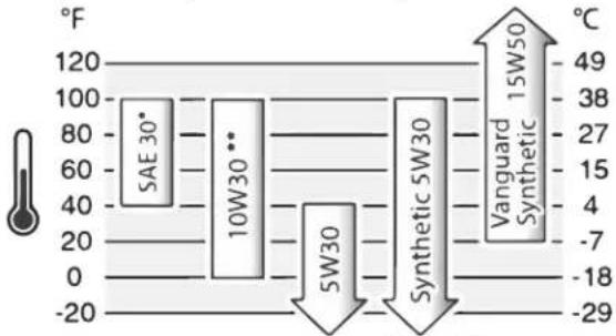
Outdoor temperatures determine the proper oil viscosity for the engine. Use the chart to select the best viscosity for the outdoor temperature range expected. Engines on most outdoor power equipment operate well with 5W30 Synthetic oil. For equipment operated in hot temperatures, Vanguard® 15W50 Synthetic oil provides the best protection.
other
| Material | Temperature (°C) | | :--- | :--- | | SAE 30* | 49 | | 10W30** | 38 | | 5W30 | 27 | | 5W30 | 15 | | 5W30 | 4 | | Vanguard | -7 | | Synthetic | -18 | | Synthetic | -29 |* Below 4°C (40°F) the use of SAE 30 will result in hard starting.
** Above 27°C (80°F) the use of 10W30 may cause increased oil consumption. Check oil level more frequently.
Checking/Adding Engine Oil
Oil level should be checked prior to each use or at least every 8 hours of operation. Keep oil level maintained.
- Make sure generator is on a level surface.
- Loosen the two maintenance cover screws and remove the side maintenance cover.
natural_image
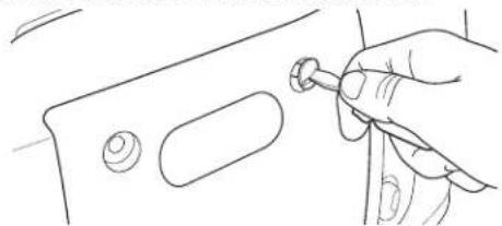
Line drawing of a hand holding a small tool with a knob, next to a panel (no text or symbols)- Clean area around oil fill, remove oil fill cap and check oil level.
natural_image
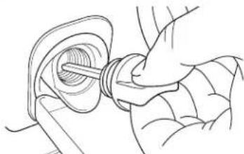
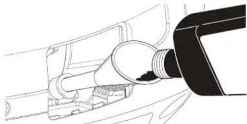
Line drawing of a hand inserting a screw into a circular component (no text or symbols)- If needed, slowly pour oil into oil fill opening to the point of overflowing.
natural_image
Line drawing of a fuel nozzle connecting a pipe into a car (no text or symbols)- Replace and tighten oil fill cap.
NOTICE Do not attempt to crank or start engine before it has been properly serviced with recommended oil. This could result in an engine failure.
- Reinstall the side maintenance cover and hand tighten the cover screws.
⚠️ CAUTION Avoid prolonged or repeated skin contact with used motor oil. Used motor oil has been shown to cause skin cancer in certain laboratory animals. Thoroughly wash exposed areas with soap and water.
KEEP OUT OF REACH OF CHILDREN. DON'T POLLUTE. CONSERVE RESOURCES. RETURN USED OIL TO COLLECTION CENTERS.
Changing Engine Oil
If you are using your generator under extremely dirty or dusty conditions, or in extremely hot weather, change the oil more often.
Change the oil while the engine is still warm from running, as follows:
- Make sure unit is on a level surface.
- Drain fuel tank by running generator until fuel tank is empty.
- Remove cover over the oil fill area.
- Clean area around oil fill and remove oil fill cap.
- Tip your generator to drain oil from oil fill into a suitable container making sure you tip your unit toward the oil filler neck. When crankcase is empty, return generator to upright position.
- Using an oil funnel, slowly pour recommended oil (about 0.4 l (13.5 oz.)) into oil fill opening. Checking oil level frequently, fill to point of overflowing.
NOTICE Pause to permit oil to settle. DO NOT overfill.
- Replace and tighten oil fill cap.
- Wipe up any spilled oil.
- Replace cover over oil fill area.
Service Air Cleaner

WARNING! Fuel and its vapors are extremely flammable which could cause burns or fire resulting in death or serious injury.
- Do not start and run engine with air filter removed.
Your engine will not run properly and may be damaged if you run it with a dirty air cleaner. Service more often if operating under dirty or dusty conditions.
- Loosen the side maintenance cover screws and remove the side maintenance cover.
- Loosen air cleaner cover screw (A) and remove air cleaner cover (B).
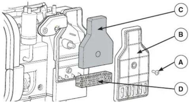
- Carefully remove foam air cleaner (C) by pulling it out towards you.
- Carefully remove pre-filter (D) by pulling it out towards you.
- Wash foam air cleaner and breather filter in liquid detergent and water only. Squeeze dry in a clean cloth.
- SATURATE foam air cleaner in clean engine oil and squeeze in a clean cloth to remove excess oil.
- Reinstall clean or new foam air cleaner inside base.
- Reinstall clean or new breather filter inside base.
- Reinstall the air cleaner cover and tighten screw.
- Reinstall the side maintenance cover and hand tighten the cover screws.
Service Spark Plug
Changing the spark plug will help your engine to start easier and run better.
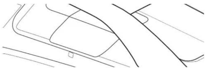
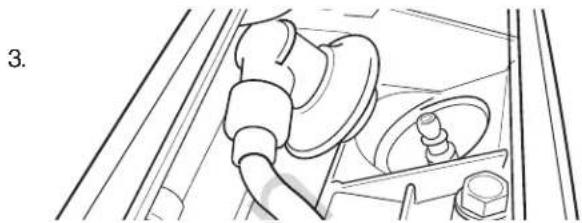
- Push in on tab with screwdriver and remove top maintenance cover.
natural_image
Line drawing of a car's rear suspension and steering wheel (no text or symbols)- Clean area around spark plug and remove spark plug boot.
natural_image
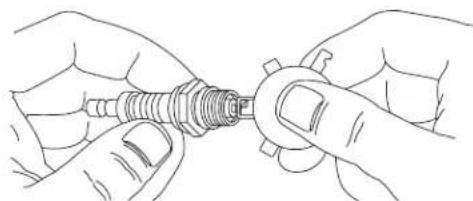
Line drawing of a car interior showing steering wheel and dashboard (no text or symbols)Remove spark plug and inspect spark plug.
-
Replace spark plug if electrodes are pitted, burned or porcelain is cracked. Use the recommended replacement spark plug. See Common Service Parts.
-
Check electrode gap with wire feeler gauge and reset spark plug gap to recommended gap if necessary (see Specifications).
natural_image
Line drawing of two hands holding a mechanical component (no text or symbols)-
Install spark plug and tighten firmly. Reinstall spark plug boot.
-
Reinstall top maintenance cover.
Inspect Muffler and Spark Arrester
The engine exhaust muffler has a spark arrester screen. Inspect the muffler for cracks, corrosion, or other damage. Inspect spark arrester screen for damage or carbon blockage. Clean if carbon blockage is found or replace if damaged. If replacement parts are required, make sure to use only original equipment replacement parts.

WARNING! Contact with muffler area could cause burns resulting in serious injury.
- Do not touch hot parts.
Clean or replace spark arrester as follows:
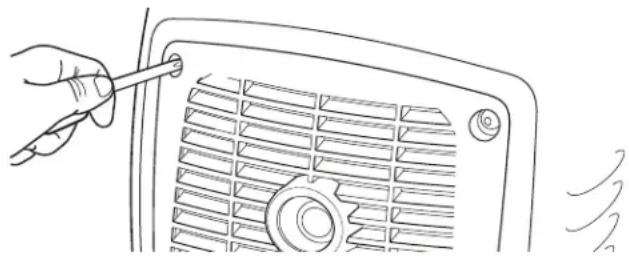
- Loosen back cover screws and remove cover.
natural_image
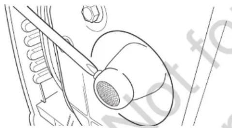
Line drawing of a hand holding a pointer inserted into a fan grille (no text or symbols)- Remove screw that attaches spark arrester screen to muffler. Remove spark arrester screen.
natural_image
Technical line drawing of a mechanical assembly with a tool and component (no text or symbols)-
Obtain a replacement screen. See Common Service Parts.
-
Reattach screen to muffler. Reattach back cover.
Common Service Parts
Air Cleaner 84003886
Spark Plug 84003884
Engine Oil Bottle 100028
Synthetic Oil Bottle 100074
Spark Arrester 703189
Contact an authorized service dealer or BRIGGSandSTRATTON.com for a full list of parts and diagrams.
Storage
If storing the unit for more than 30 days, use the following guidelines to prepare it for storage.
Long Term Storage Instructions
- Clean the generator as outlined in Cleaning.
- Change engine oil while engine is still warm, drain oil from crankcase. Refill with recommended grade. See Changing Engine Oil.
- Treat or drain fuel from generator as fuel can become stale when stored over 30 days.
Each time you fill the container with fuel, add STA-BIL 360°® PROTECTION™ to the fuel as specified by the manufacturer's instructions. This keeps fuel fresh and decreases fuel-related problems or contamination in the fuel system.
It is not necessary to drain fuel from the engine when STABIL 360°® PROTECTION™ is added as instructed. Before storage, turn the engine ON for 2 minutes to move the fuel and stabilizer through the fuel system.
If fuel in the engine has not been treated with STA-BIL 360°® PROTECTION™, it must be drained into an approved container. Then run the engine until it stops from lack of fuel.

WARNING! Fuel and its vapors are extremely flammable and explosive which could cause burns, fire or explosion resulting in death or
serious injury.
- When storing fuel or equipment with fuel in tank, store away from furnaces, stoves, water heaters, clothes dryers or other appliances that have pilot light or other ignition source because they could ignite fuel vapors.
- When draining fuel, turn generator engine off and let it cool at least 2 minutes before removing fuel cap. Loosen cap slowly to relieve pressure in tank. Drain fuel tank outdoors. Keep fuel away from sparks, open flames, pilot lights, heat, and other ignition sources.
-
Check fuel lines, tank, cap and fittings frequently for cracks or leaks. Replace if necessary.
-
Turn the engine switch to the off position.
-
Store generator in clean, dry area and cover with a suitable protective cover that does not retain moisture.

WARNING! Storage covers could cause a fire resulting in death or serious injury.
- Do not place a storage cover over a hot or running generator. Let equipment cool for a sufficient time before placing the cover on the equipment.
| Problem Cause Correction | ||
| Engine is running, but no AC output is available. | 1. One of the circuit breakers is open.2. Poor connection or defective cord set.3. Connected device is bad.4. Red LED light is steady. Generator is overloaded or overheated. | 1. Reset circuit breaker.2. Check and repair.3. Connect another device that is in good condition.4. See Generator Capacity. Press MAIN RESET button on control panel. |
| Engine runs well at no-load but “bogs down” when loads are connected. | 1. Generator is overloaded. | 1. See Generator Capacity. |
| Engine will not start; starts and runs rough or shuts down when running. | 1. Engine switch is in off position.2. Low oil indicator light comes on. Low oil level.3. Dirty air cleaner.4. Out of fuel.5. Spark plug wire not connected to spark plug.6. Flooded with fuel. | 1. Turn engine switch to on position.2. Fill crankcase to proper level or place generator on level surface.3. Clean or replace air cleaner.4. Fill fuel tank.5. Connect wire to spark plug.6. Wait 5 minutes and re-crank engine. |
| Engine shuts down and CO shutdown system LED blinks red (•• ••). | 1. Generator improperly located. | 1. Move generator to an open, outdoor area. Air out premises (e.g. open windows and doors) before reoccupying. See Carbon Monoxide (CO) Shutdown System. |
For all other issues, see a Briggs & Stratton authorized dealer.
Specifications
Rated Wattage ^* 2,800
Starting Wattage ^** 3,400
Current at 230 Volts AC....12.2 Amps
Current at 12 Volts DC....5.0 Amps
Current at 5 Volts DC....2.1 Amps
Frequency....50 Hz
Phase .... Single Phase
Displacement 171 cc (10.44 cu. in.)
Spark Plug Gap 0.6-0.7 mm (0.024-0.028 in.)
Fuel Capacity 4.0 Liters (1.0 U.S. Gallons)
Oil Capacity ....0.4 Liters (13.5 Ounces)
Sound Pressure @ 7 m§....78 dBA
BRIGGS & STRATTON PRODUCTS WARRANTY POLICY
Limited Warranty
Briggs & Stratton warrants that, during the warranty period specified below, it will repair or replace, free of charge, any part that is defective in material or workmanship or both. Transportation charges on product submitted for repair or replacement under this warranty must be borne by purchaser. This warranty is effective for and is subject to the time periods and conditions stated below. For warranty service, find the nearest Authorized Service Dealer in our dealer locator map at www.briggsandstratton.com. The purchaser must contact the Authorized Service Dealer, and then make the product available to the Authorized Service Dealer for inspection and testing.
There is no other express warranty. Implied warranties, including those of merchantability and fitness for a particular purpose, are limited to the warranty period listed below, or to the extent permitted by law. Liability for incidental or consequential damages are excluded to the extent exclusion is permitted by law. Some states or countries do not allow limitations on how long an implied warranty lasts, and some states or countries do not allow the exclusion or limitation of incidental or consequential damages, so the above limitation and exclusion may not apply to you. This warranty gives you specific legal rights and you may also have other rights which vary from state to state or country to country.**
WARRANTY PERIOD
Consumer Use Commercial Use
36 months ▲ 12 months
▲ Battery (if equipped) 3 months consumer use, none commercial use.
** In Australia - Our goods come with guarantees that cannot be excluded under the Australian Consumer Law. You are entitled to a replacement or refund for a major failure and for compensation for any other reasonably foreseeable loss or damage. You are also entitled to have the goods repaired or replaced if the goods fail to be of acceptable quality and the failure does not amount to a major failure. For warranty service, find the nearest Authorized Service Dealer in our dealer locator map at BRIGGSandSTRATTON.COM, or by calling 1300 274 447, or by emailing or writing to salesenquires@briggsandstratton.com.au, Briggs & Stratton Australia Pty Ltd, 1 Moorebank Avenue, NSW, Australia, 2170.
The warranty period begins on the date of purchase by the first retail or commercial consumer. "Consumer use" means personal residential household use by a retail consumer. "Commercial use" means all other uses, including use for commercial, income producing or rental purposes. Once a product has experienced commercial use, it shall thereafter be considered as a commercial use product for purposes of this warranty.
Save your proof of purchase receipt. If you do not provide proof of the initial purchase date at the time warranty service is requested, the manufacturing date of the product will be used to determine the warranty period. Product registration is not required to obtain warranty service on Briggs & Stratton products.
ABOUT YOUR WARRANTY
Warranty service is available only through Briggs & Stratton Authorized Service Dealers. Most warranty repairs are handled routinely, but sometimes requests for warranty service may not be appropriate. This warranty covers only defects in materials or workmanship. It does not cover damage caused by improper use or abuse, improper maintenance or repair, normal wear and tear, or stale or unapproved fuel.
Improper Use and Abuse - The proper, intended use of this product is described in the Operator's Manual. Using the product in a way not described in the Operator's Manual or using the product after it has been damaged will not be covered under this warranty. Warranty coverage will also not be provided if the serial number on the product has been removed or the product has been altered or modified in any way, or if the product has evidence of abuse such as impact damage or water/chemical corrosion damage.
Improper Maintenance or Repair - This product must be maintained according to the procedures and schedules provided in the Operator's Manual, and serviced or repaired using genuine Briggs & Stratton parts or equivalent. Damage caused by lack of maintenance or use of non-original parts is not covered by warranty.
Normal Wear and Tear - Like most mechanical devices, your unit is subject to wear even when properly maintained. This warranty does not cover repairs when normal use has exhausted the life of a part or the equipment. Maintenance and wear items such as filters, belts, cutting blades, and brake pads (except engine brake pads) are not covered by warranty due to wear characteristics alone, unless the cause is due to defects in material or workmanship.
Stale or Unapproved Fuel - In order to function correctly, this product requires fresh fuel that conforms to the criteria specified in the Operator's Manual. Engine or equipment damage caused by stale fuel or the use of unapproved fuels (such as E15 or E85 ethanol blends) is not covered by warranty.
Other Exclusions - This warranty excludes damage due to accident, abuse, modifications, alterations, improper servicing, freezing or chemical deterioration. Attachments or accessories that were not originally packaged with the product are also excluded. There is no warranty coverage on equipment used for primary power in place of utility power or on equipment used in life support applications. This warranty does not include used, reconditioned, second-hand, or demonstration equipment or engines. This warranty also excludes failures due to acts of God and other force majeure events beyond the manufacturer's control.
80088366EN (Rev. A)
- Outdoor Portable Generator
- Operator's Manual
- Table of Contents
- Equipment Description
- System Ground
- Special Requirements
- Operation
- Step 1: Safe Location
- Operation Location to Reduce the Risk of Carbon Monoxide Poisoning
- Carbon Monoxide Alarm(s).
- Prevent Carbon Monoxide (CO) Poisoning
- Operation Location to Reduce the Risk of Fire
- Step 2: Oil and Fuel
- Low Oil Indicator
- E10 E15
- High Altitude
- Transporting
- Step 3: Generator Start Up
- Step 4: Connecting Electrical Loads
- To Restore Home Power Using a Transfer Switch
- To Restore Power Using Extension Cords
- Volt DC USB Ports
- Volt DC Receptacle
- Volt AC, 15 Amp Receptacles
- Output Indicator OK!
- Overload Alarm
- Parallel Operation
- NOTICE
- QPT (QUIET POWER TECHNOLOGY)
- STATSTATION™
- Load Monitor
- Hour Meter
- Maintenance Reminder
- Generator Capacity
- Example
- Power Management
- Carbon Monoxide (CO) Shutdown System
- Step 5: Generator Shutdown
- Maintenance
- Maintenance Schedule
- General Recommendations
- Emissions Control
- Cleaning
- Engine Maintenance
- Oil Recommendations
- Checking/Adding Engine Oil
- Changing Engine Oil
- Service Air Cleaner
- Service Spark Plug
- Inspect Muffler and Spark Arrester
- Clean or replace spark arrester as follows:
- Common Service Parts
- Storage
- Long Term Storage Instructions
- Specifications
- BRIGGS & STRATTON PRODUCTS WARRANTY POLICY
- Limited Warranty
- WARRANTY PERIOD
- Consumer Use Commercial Use
- ABOUT YOUR WARRANTY
Brand : BRIGGS & STRATTON
Model : P3400
Category : Generator