
EziSalt - Home Appliances ZODIAC - Free user manual and instructions
Find the device manual for free EziSalt ZODIAC in PDF.


| Product Type | Salt-based water softener / chlorinator |
| Brand | Zodiac |
| Model | EziSalt |
| Intended Use | Residential water treatment |
| Dimensions (approx.) | 45 x 30 x 25 cm (17.7 x 11.8 x 9.8 in) |
| Weight (approx.) | 12 kg (26.5 lb) |
| Power Supply | 230 V / 50 Hz, 10 A |
| Maximum Flow Rate | 1.5 m³/h (6.6 GPM) |
| Salt Capacity | 25 kg (55 lb) |
| Control Interface | Digital display with push buttons |
| Regeneration Mode | Automatic, time-based or demand-initiated |
| Functions | Water softening, reduced scale buildup, improved lathering |
| Maintenance | Periodic salt refill, annual cleaning of brine tank |
| Cleaning | Wipe exterior with damp cloth; do not use abrasive cleaners |
| Safety Features | Overload protection, salt level monitoring, bypass valve |
| Spare Parts Available | Resin, valves, seals, control board, brine well |
| Repairability | Modular design; parts replaceable by qualified technician |
| Certifications | CE, WQA (Water Quality Association) |
| Warranty | 2 years limited |
Frequently Asked Questions - EziSalt ZODIAC
User questions about EziSalt ZODIAC
0 question about this device. Answer the ones you know or ask your own.
Ask a new question about this device
Download the instructions for your Home Appliances in PDF format for free! Find your manual EziSalt - ZODIAC and take your electronic device back in hand. On this page are published all the documents necessary for the use of your device. EziSalt by ZODIAC.
USER MANUAL EziSalt ZODIAC
EziSalt Saltwater Chlorinator
WARNING
FOR YOUR SAFETY - This product must be installed and serviced by a qualified installer in accordance with the latest enforced version of AS/NZ 3000 and any other applicable local installation codes. Before installing this product, read and follow all warning notices and instructions that accompany this product. Failure to follow warning notices and instructions may result in property damage, personal injury, or death. Improper installation and/or operation will void the warranty.
Improper installation and/or operation can create unwanted electrical hazard which can cause serious injury, property damage, or death.

For full warranty terms and conditions and to register your warranty, simply visit www.zodiac.com.au/warranty and complete your details. Or scan the QR code and be taken directly to the registration page
Record your Equipment details here for quick reference:
Model No.: ____
Serial No.:
Refer to the following websites for information on warranty and service in your country:
• Australia, NZ, Asia and Sth Pacific go to www.zodiac.com.au
EQUIPMENT INFORMATION RECORD
DATE OF INSTALLATION
INSTALLER INFORMATION
INITIAL PRESSURE GAUGE READING (WITH CLEAN FILTER)
PUMP MODEL HORSEPOWER
FILTER MODEL
CONTROL PANEL MODEL SERIAL NUMBER
NOTES:
Table of Contents
Section 1. Important Safety Instructions.....4
Section 2. System Overview....6
2.1 Contents....6
2.2 Specifications 6
2.3 Dimensions....6
2.4 Materials and Tools 6
Section 3. Plumbing....7
Section 4. Install Controller .... 8
4.1 Mount the Bracket....8
4.2 Electrical Connections....8
Section 5. Prepare and Balance the Pool .... 10
5.1 Water Chemistry Table....10
Section 6. Operation....10
6.1 User Interface Overview....10
6.2 Initial start-Up 11
Section 7. Installing and Assigning Equipment .... 12
7.1 Filter Pump....12
7.2 Aux/Lights....12
7.3 Programming/ Timers....14
7.4 Reversing 15
7.5 Slave Mode 16
Section 8. Help Menu....16
Section 9. Inspecting and Cleaning the Electrode.... 17
Section 10. Winterizing....17
10.1 Reopening the Pool....17
Section 11. General Maintenance....18
11.1 Cell Maintenance....18
11.2 Maintenance Schedule....18
Section 12. Troubleshooting....19
Section 1. Important Safety Instructions
READ AND FOLLOW ALL INSTRUCTIONS
All electrical work must be performed by a qualified installer and conform to all national, state, and local codes. When installing and using this electrical equipment, basic safety precautions should always be followed, including the following:
DANGER
To reduce the risk of severe injury or death, do not remove the suction fittings of your spa or hot tub. Never operate a spa or hot tub if the suction fittings are broken or missing. Never replace a suction fitting with one rated less than the flow rate marked on the equipment assembly.
WARNING
Prolonged immersion in hot water may induce hyperthermia. Hyperthermia occurs when the internal temperature of the body reaches a level several degrees above the normal body temperature of 37° C. The symptoms of hyperthermia include dizziness, fainting, drowsiness, lethargy, and an increase in the internal temperature of the body. The effects of hyperthermia include: 1) unawareness of impending danger; 2) failure to perceive heat; 3) failure to recognize the need to exit spa; 4) physical inability to exit spa; 5) fetal damage in pregnant women; 6) unconsciousness resulting in a danger of drowning.
WARNING
To Reduce the Risk of Injury -
a) The water in a spa should never exceed 40° C. Water temperatures should remain between 38° C and 40° C. The water in a spa should never exceed 40° C. Water temperatures between 38° C and 40° C are considered safe for a healthy adult. Lower water temperatures are recommended for young children and when spa use exceeds 10 minutes.
b) Since excessive water temperatures have a high potential for causing fetal damage during the early months of pregnancy, pregnant or possibly pregnant women should limit spa water temperatures to 38° C. Before entering a spa or hot tub, the user should measure the water temperature with an accurate thermometer since the tolerance of water temperature-regulating devices varies.
d) The use of alcohol, drugs, or medication before or during spa or hot tub use may lead to unconsciousness with the possibility of drowning.
e) Obese persons and persons with a history of heart disease, low or high blood pressure, circulatory system problems, or diabetes should consult a physician before using a spa.
f) Persons using medication should consult a physician before using a spa or hot tub since some medication may induce drowsiness while other medication may affect heart rate, blood pressure, and circulation.
WARNING
Risk of electric shock - Install the controller at least 3.5 metres from the inside wall of the pool and/or hot tub using non-metallic plumbing.
Children should not use spas or hot tubs without adult supervision.
Do not use spas or hot tubs unless all suction guards are installed to prevent body and hair entrapment.
People using medications and/or having an adverse medical history should consult a physician before using a spa or hot tub.
WARNING
To avoid injury ensure that you use this control system to control only packaged pool/spa heaters which have built-in operating and high limit controls to limit water temperature for pool/spa applications. This device should not be relied upon as a safety limit control.
WARNING
People with infectious diseases should not use a spa or hot tub.
To avoid injury, exercise care when entering or exiting the spa or hot tub.
Do not use drugs or alcohol before or during the use of a spa or hot tub to avoid unconsciousness and possible drowning.
Before entering a spa or hot tub, measure the water temperature with an accurate thermometer.
Do not use a spa or hot tub immediately following strenuous exercise.
Prolonged immersion in a spa or hot tub may be injurious to your health.
Do not permit any electric appliance (such as a light, telephone, radio, or television) within 3.5 metres of a spa or hot tub.
The use of alcohol, drugs or medication can greatly increase the risk of fatal hyperthermia in hot tubs and spas.
Water temperature in excess of 38° C may be hazardous to your health.
WARNING
A terminal bar marked "GROUND" is provided within the controller. To reduce the risk of electrical shock which can cause serious injury or death, connect this terminal bar to the grounding terminal of your electric service or supply panel with a continuous copper conductor having green insulation and one that is equivalent in size to the circuit conductors supplying this equipment in accordance with AS/NZ 3000 - 2007. In addition, where required, bonding should be extended in accordance with AS/NZ 3000 - 2007 to any metal ladders, water pipes, or other metal within 3.5 m of the pool/spa.

Attention Installer: Install to provide drainage of compartment for electrical components.
SAVE THESE INSTRUCTIONS
Section 2. System Overview
2.1 Contents
Before starting, check that you have the correct parts as indicated in Table 1. If any parts are missing or incorrect, please call your local distributor or technical support at 1300 763 021 for assistance.
2.1.1 Salt Chlorinator System

| EziSalt Saltwater Chlorinator |
| a. Controller |
| b. Wall Mount Bracket |
| c. Wall Mount Screws ∅7 mm (X2) |
| d. Wall Mount Anchor (X2) |
| e. Electrolytic Cell |
| f. Screw Barrel Unions (X2) |
| g. 40mm Glue On Adapter (X2) |
Table 1. Salt Chlorinator System Contents
2.2 Specifications
2.2.1 Salt Chlorinator System
| EziSalt 24 EziSalt 40 | ||
| Nominal chlorine production 24 g/h 40 g/h | ||
| Nominal output amps 5.0 A 7.2 A | ||
| Required salt level 4000ppm | ||
| Power supply voltage 240 VAC - 50 Hz | ||
| Electric power 200 W | ||
| Protection index IP43 | ||
| Flow through the cell | Min. 80 Lpm | |
| Operating water temperature | 10°C - 40°C | |
Table 2. Salt Chlorinator System Specifications
2.3 Dimensions
2.3.1 Controller

Figure 1. Controller Dimensions
2.3.2 Cell

Figure 2. Electrolytic Cell Dimensions
2.4 Materials and Tools
2.4.1 Controller
Tools Needed for Installation
- Power Drill
- 7 mm Drill Bit - Hammer Drill Bit (only necessary to drill into brick or concrete)
- Pencil or Marking Pen
- Flat Head Screwdriver
- Pozidiv Screwdriver
- Small Flathead or Slotted Screwdriver
2.4.2 Cell
Tools Needed for Installation
- PVC Cutter
- PVC Cement
- Pencil or Marking Pen
- Check Valve
- 40 mm PVC Pipe
Section 3. Plumbing
The cell must be plumbed in a position that is accessible for maintenance and within 2 meters of the controller. The cell should be the last piece of equipment in the circulation system. The cell must be installed horizontally, level and with correct flow orientation, see Figure 3.
- If you intend to plumb the cell on a bypass, the bypass must be equipped with Isolation valves, see Figure 3.
- Plumb the cell inlet and outlet on vertical lengths of 40 mm PVC pipe. The cell inlet and outlet ports are 11.5 cm apart, see Figure 2. The inlet of the cell is on the side closest to the electrical lead, see Figure 4.
- Put the unions onto the inlet and outlet pipes, see Figure 4.
- Glue the adapters directly onto the pipes.
- Ensure the o-rings are seated properly on the adapters.
- Secure the cell to the plumbing by tightening the unions hand tight. DO NOT OVERTIGHTEN.
- Double check cell orientation. The cell inlet is closest to the cell electrical lead.

Figure 3. Plumbing Cell Only
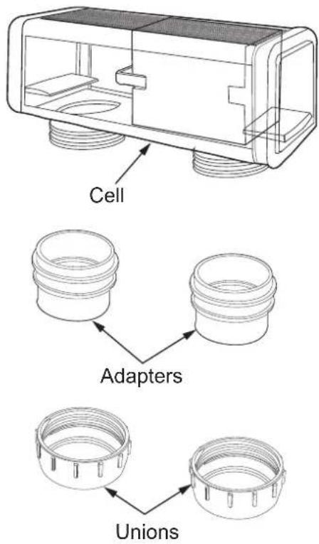
Figure 4. CellPlumbingAssembly
WARNING
- The cell must be installed horizontally and level. Improper installation can lead to gas build up which could result in equipment damage or serious injury.
- The cell must be the last piece of equipment on the return line, see Figure 3.
- It is recommended in all installations that the cell is installed on a bypass equipped with isolation valves, see Figure 3.
- In order to avoid load loss, installing the cell on a bypass is MANDATORY if system flow rated exceeds 300 Lpm, see Figure 3.
- If installing on a bypass, use a downstream check valve instead of a manual valve to prevent improper back flow into the cell.
Section 4. Install Controller
The controller should be located at or near the equipment pad, at least 3.5 metres or more away from the inside wall of the pool/spa, 1.5 metres off the ground, and within 2 meters of the cell. All national, state, and local codes are applicable.
4.1 Mount the Bracket
- Determine the controller location.
- Use the enclosed bracket to mark the mounting surface through the screw holes.
- Drill surface with 7 mm bit.
- Install the included wall anchors.
- Hang bracket using the included screws.
- Hang the controller on the wall bracket and slide to the right to secure in place.
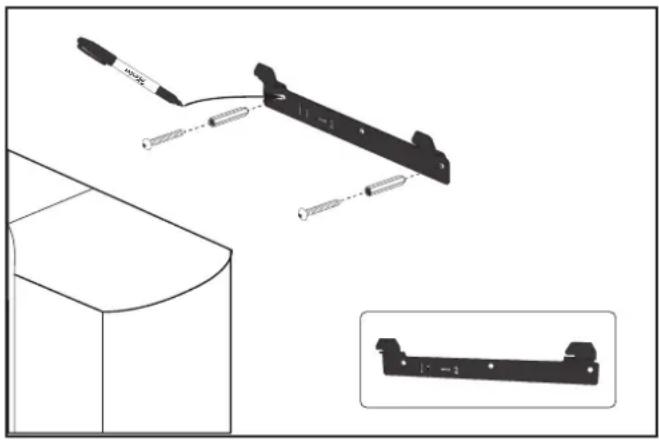
Figure 5. Controller Mount
4.2 Electrical Connections
WARNING
FOR YOUR SAFETY: This product must be serviced by a professional pool/spa service technician as described on the front cover of this manual. The procedures in this manual must be followed exactly. Failure to follow warning notices and instructions may result in property damage, serious injury, or death. Improper installation and/or operation will void the warranty.
The controller must be permanently powered by connection to a 30 mA residential circuit breaker.
4.2.1 Controller Enclosure Wiring
- Wire low voltage connections on the low voltage side of the enclosure, see Figure 7.
- Wire high voltage connections on the high voltage side of the enclosure, see Figure 7.
- Use the internal labels (low voltage - yellow, high voltage - orange) to identify connection points.
- Use the cable ties provided to secure internal wiring to the controller frame.
- Pass cables through the appropriately labeled strain relief ports. It may be necessary to pierce the strain relief grommet prior to passing the cables through it.
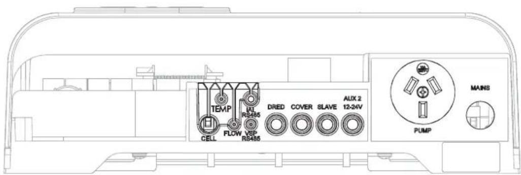
Figure 6. Controller Connection Ports
| NAME TYPE | FUNCTION | |
| SENS Input Not Used | ||
| PUMP Input Not Used | ||
| CELL Output Connection of the electrolysis | cell | |
| UI Output Connection of the user interface | ||
| TEMP Input Not Used | ||
| Flow Input Not Used | ||
| iAL RS485 Input Not Used | ||
| VSP RS485 Output Not Used | ||
| DRED Input DRED Function (Demand Response Enabled Device) – for Australia only | ||
| COVER | Input | Pool cover contact – lower the chlorine production(dry contact: cover open = open contact/cover closed = closed contact) |
| SLAVE | Input Not Used | |
| AUX 2 12-24V | Output | Light control function - turn OFF/ON, timer and color selection(Light relay box code required. Use Part # WW000222.) |
| AUX 1 230V | Output Not Used | |
| PUMP 230V | Output 230 V | Power supply for the filtration pump Maximum 8A |
| MAINS | Input Device | power supply 230 VAC – 50Hz |
Table 3. Controller Wiring Positions
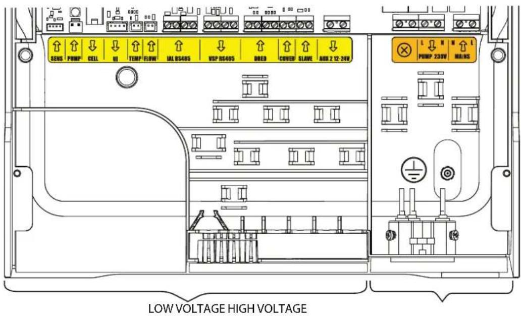
Figure 7. Controller Wiring
Section 5. Prepare and Balance the Pool
5.1 Water Chemistry Table
Test and maintain correct water balance throughout the season, according to the table.
| Free Chlorine | pH Total Alkalinity (ppm) | Calcium Hardness (ppm) | Cyanuric Acid (ppm) | Salt Level (ppm) | Metal | |
| Australian Standard | 1 -3 7.2 - 7.8 | 60 - 200 | 100 - 400 *** | up to 50 4000 | - 7000 x | |
| Ideal range 1 | -3 7.4 80 - 140 90 | 300 up to 50 4000 | at 27°C < 0.10 ppm | |||
| To Increase Add chlorine or increase equipment output | Add buffer or soda ash (sodium carbonate) | Add sodium bicarbonate | Add calcium chloride | Add cyanuric acid | Add salt or minerals ** | x |
| To Decrease | Add muriatic acid | Add muriatic acid or dry acid | Partially drain and refill pool* | Partially drain and refill pool* | Use 'Metal Remover' | |
| In Season Testing Frequency | Weekly | Weekly | Weekly | Weekly | Monthly | Monthly |
* Fill pool with water from the mains water supply. Do not use rain water or well water.
** Do not add salt directly into the skimmer. Do not initiate electrolysis until salt has fully dissolved.
*** Reading is True Calcium Hardness, not Total Hardness.
Table 4. Water Chemistry
Section 6. Operation
6.1 User Interface Overview
CAUTION
To avoid to avoid risk of serious damage to the equipment and/or electrocution which could result in serious injury or death, ensure that all salt added to the pool has completely dissolved before activating the chlorination function of your system.
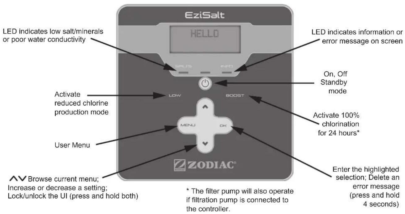
Figure 8. Controller User Interface
6.2 Initial start-Up
The following setting must be configured at the initial start up of the device. Settings can be changed or updated at a later time using the general menu, details can be found in Section 7.
From factory, the chlorination is set at 50 %. It can be set between 0 and 100 % in 10 % increments from the “main screen” by pressing ▲▼. The set value is valid until the next modification.
6.2.1 System Power
- Press ⏻ to enter Standby mode.
- Press in to start chlorination and filtration.
- Press and hold ⏻ for 3 seconds to turn the controller off.
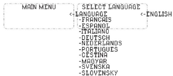
6.2.2 Language
- Press .MENU
- Use to select "Language" then press OK.
- Use to browse language the options.
- Press to make a selection.
6.2.3 Set Clock
- Press MENU.
- Use to select "Programming" then press OK.
- Use to select "Clock" then press OK.
- Use to set hour then press . OK
- Use to set minutes then press . OK
NOTE: Press and hold or to increment time by 10.
- Press to exit.

7.2.1 Assign Lights
1. Press  2. Use   3. Use   4. Use   5. Use   6. Use 7. Press
  7.2.2 White Light Operation
1. Press MENU. 2. Use to select "Aux/Light" then press . OK 3. Use to select "Aux 2/Light" then press . OK 4. Use to select "On", "Off", or "Set Timers", then press ____. 5. Press to exit. 7.2.3 Color Light Operation
1. Press MENU. 2. Use to select "Aux/Light" then press . OK 3. Use to select "Aux 2/Light" then press . OK 4. Use to select desired color, "Off", "On" or "Define Color", then press OK. 5. If "Define Color" selected, use to select desired color then press OK. 6. Press to exit.  NOTE: Colour sequence is relevant for Zodiac colour lights only. If other manufacturers lights are installed the colour selection will vary7.3 Programming/ Timers
The controller has two internal operating timers. The timers are used to define the length of time for the filter pump to operate, and the length of time for the Salt Water Chlorinator (SWC) to produce chlorine. This offers the user the advantage of running their variable speed pump longer at lower flow rates, without having the chlorinator producing the whole time. In order to complete the timer program, it is necessary to enter and validate both ON and OFF times. If no timer is set, the filtration and / or chlorination will run continuously The filtration operating times must be sufficient to correctly treat the water.Example - single speed pump:
In Season filtration time: 8-10 hours per day. Off Season filtration time: 4-5 hours per day. Example - variable speed pump (when running at lower speeds): In Season filtration time: 12-14 hours per day In Season SWC time: 8-10 hours per day Off Season filtration time: 10-12 hours per day Off Season SWC time: 4-5 hours per day Once validated, The SWC will adopt the same timers as the filtration pump. The chlorination time must be equal or shorter than the filtration time. The device will not accept a SWC timer longer than or outside the programmed filtration time.7.3.1 Reset Timers
1. Press MENU 2. Use to select "Programming" then press OK. 3. Use to select "Reset Timers" then press . OK The selected timers will be reset to 00:00.7.3.2 Operation With an External Timer
In order for the controller to operate with an external timer. All controller programs must be cleared and the device must be on. After the connection to the external timer is made, turn the controller off then back on again.7.3.3 Filter Pump Programming
1. Press MENU 2. Use to select "Programming" then press OK. 3. Use to select "Filter Pump" then press . OK 4. Use to select "Pump Timer 1" or "Pump Timer 2" then press OK. 5. Use to select the hour for the filtration on time then press OK. 6. Use to select the minutes for the filtration on time then press OK. 7. Use to select the hour for the filtration off time then press OK. 8. Use to select the minutes for the filtration off time then press OK. 9. Press to exit.  10. When a filtration program has been confirmed the letter "P" is displayed on the top right of the screen.  Manual activation of the device (pressing ⏻) takes priority over the timer. If no filter pump is connected, the controller will only start chlorination. If a filter pump has been connected the filter pump will start along with chlorination. All programs will still be valid and will resume normal operation the next cycle.7.3.4 Salt Water Chlorinator (SWC) Programming
If a filtration program has been set, the chlorination program will be identical to the filtration program(s) by default. They can be changed, however the chlorination program(s) cannot be activated outside of the filtration Program(s) for safety reasons. 1. Press MENU 2. Use to select "Programming" then press OK. 3. Use to select "SWC" then press . OK 4. Use to select "SWC Timer 1" or "SWC Timer 2" then press OK. 5. Use to select the hour for the SWC on time then press OK. 6. Use to select the minutes for the SWC on time then press OK. 7. Use to select the hour for the SWC off time then press OK. 8. Use to select the minutes for the SWC off time then press OK. 9. Press to exit.  The "T" symbol is displayed in the upper right hand corner of the LCD display on the home screen if the programming is valid. The "P" symbol is displayed in the upper right-hand corner of the LCD display on the home screen if a valid filter pump and chlorinator program has been set. 7.3.5 AUX/Lights Programming
1. Press MENU 2. Use to select "Programming" then press OK. 3. Use to select "AUX/Lights" then press . OK 4. Use to select "AUX 2 Timer" then press OK. 5. Use to select the hour for the AUX on time then press OK. 6. Use to select the minutes for the AUX on time then press OK. 7. Use to select the hour for the AUX off time then press OK. 8. Use to select the minutes for the AUX off time then press OK. 9. Press to exit. 7.4 Reversing
IMPORTANT
Adjusting your cell reversal times will result in voiding of warranty. You must consult with Zodiac on 1300 763 021 or your local pool care professional before making any adjustments. The chlorinator uses a smart polarity reversal system. Periodic polarity reversal will prevent scaling of the cell plates. The time between each reversal is factory set at 5 hours. This setting is optimal for most water conditions. However, Depending on the calcium hardness of the water, you may need to adjust the reversal time. More calcium in the water will require less time between reversals. Water with less calcium can be given more time between reversals. Shorter reversal times will cause more wear of your cell plates. The polarity reversal interval can be adjusted from 2 to 8 hours in 1-hour steps. 1. Press 2. Use to select "Reversing" then press 3. Use to select set hours then press.    4. Press to exit.  During reversal, chlorination is stopped for a few minutes. No message is displayed on the screen. Normal operation will resume after the reversal.7.5 Slave Mode
NOTE: It is not recommended to use Slave Mode unless you have experience with multiple control devices operating your pool. Slave mode is applicable when the chlorinator is connected to a third-party control device that uses a chlorine/sanitiser sensor (such as an ORP sensor). When in slave mode the chlorinator passes control of turning chlorine production on/off to the third party controller. NOTE: Slave mode is not used when connected to a general pool automation controller such as AquaLink. It only applies to an external controller that commands sanitiser output. To enable this function, the third party controller must be connected to the “slave” connection point in the low voltage raceway see Table 5 and Figure 10 for wiring detail. Boost and Low modes will remain operational from the controller. However, SWC programs will be deactivated. Chlorination output will be maintained at 100%. 1. Connect the external controller at the slave connection point in the low voltage raceway see Table 3 and Figure 7 for wiring details. 2. Press MENU. 3. Use to select "Slave Mode" then press OK. 4. Use to select "YES" or "NO" then press . OK 5. Press to exit.  Slave mode only controls the chlorination. Filtration pump, AUX, lights and other functions are still valid. Pressing 📍 All take priority over Slave mode. LOW / COVER / BOOST modes takes priority over Slave modeSection 8. Help Menu
The chlorinator will automatically notify you of any problems by displaying error messages. To help with the understanding of these messages, the controller has a troubleshooting assistance menu which gives the meanings and the action to take to solve the problem. 1. Press .MENU 2. Use to select "Help Menu" then press . OK 3. Use to select the error message then press OK 4. The display will automatically scroll through a certain number of suggested solutions to explain what to do. Once automatic scrolling is complete, the chlorinator automatically returns to the "Troubleshooting" menu. 5. Press MENU to exit.Section 9. Inspecting and Cleaning the Electrode
In areas that experience calcium hardness the cell electrode will benefit from cleaning. 1. Switch off the filter pump and chlorine generator, close necessary valves and unplug the cell terminal cap. 2. Unscrew the cell from the barrel unions and invert the cell so it is upside down with the cell ports facing up and pour an appropriate amount of cell cleaning solution to cover the cell plates. 3. We recommend using Zodiac Salt Chlorinator Cell Cleaner to clean the electrode. However, you can mix your own by carefully adding one (1) part of Hydrochloric (Muriatic) acid to ten (10) parts water. Stronger solutions will shorten terminal life. 4. Allow the cleaning solution to dissolve the calcium deposits for about 10 minutes. NOTE: Dispose of the cleaning solution at an approved Council Depot and never into storm water or sewage drains. 5. Rinse out the cell with tap water and refi t onto the barrel unions screwing them on fi rmly (ensure that the o'rings are seated correctly). 6. Reset valves and switches. 7. Turn pump and controller on. 8. Confir rm chlorine output and settings on the power pack. Timer programs will be automatically retained.  Figure 10. Cleaning the ElectrodeSection 10. Winterizing
Active winterizing leaves the filter pump and chlorinator running during the winter. However the colder the water temperature the greater the wear and tear on the cell, it is recommended to reduce output and/or your filtration times as temperature drops. If temperatures drop below 10° C, the chlorination cell should be reduced as much as possible. Passive winterization calls for the pool to be shut down. Water levels will need to be lowered and the piping will need to be drained. The cell electrode can be left in place with isolation valves open.10.1 Reopening the Pool
Required actions: 1. Adjust the water level (too much or too little) 2. Check the water parameters. 3. TAC/TH/pH/Salinity/Chlorine/Stabilizing Agent/Copper/Metals. 4. Adjust the parameters to obtain a balanced, healthy pool, see Section 5. 5. Check the condition of the equipment (pump, fi Iter, chlorinator, electrolytic cell). 6. Where necessary, check the sensors, clean if needed and re-calibrate. 7. Once the salt level has reached the required level of 4000ppm and has dissolved in the water, restart the salt chlorinator.Section 11. General Maintenance
If the supply cord is damaged, it must be replaced by Zodiac ,its service agent or a similarly qualified person in order to avoid a hazard. WARNING
Operating the chlorinator with less than 3000 ppm of dissolved salt in the water may cause damage to the cell and will void the warranty. Never start the chlorinator, until the correct quantity of salt has been added and dissolved in your pool water.11.1 Cell Maintenance
Your EziSalt Saltwater Chlorinator has an automatic cleaning feature, that under normal conditions, will keep the cell plates clear of deposits of salt and calcium. The cell has a negative charge sensor that monitors the flow and salt levels of the water. This sensor is designed to be fail safe. As it is negative charge deposits of calcium or other debris that may be deposited on it, causing an indication of low salt or no flow condition. Should a low salt condition be indicated, have your salt level checked at your local pool shop. If the low salt condition persists, or a no flow condition is indicated when the supply pump is operating, you may need to manually clean your EziSalt Saltwater Chlorinator Cell. See Section 9 for cleaning instructions.11.2 Maintenance Schedule
The EziSalt Saltwater Chlorinator incorporates moving parts and withstands high velocity water with chemicals in it. Some of these parts will wear in the normal course of use and require regular checks and maintenance. Performing these checks and maintenance will identify parts that have worn and require repair/replacement before further serious damage is sustained. A small amount of regular care and attention to your pool equipment will help ensure long life and trouble free performance. To protect against extremes of temperature, your unit is vented to allow expensive electronics to cool. Ants and some insects are often attracted to the warmer, dry environment inside the enclosure. We recommend that, with power turned off, you spray a surface insecticide on the surfaces surrounding the control to prevent ant and insect ingress. Repeat every three months or as necessary. NOTE: Regular maintenance is important to ensure long life and trouble free performance of your pool equipment. If unable to perform the maintenance yourself, contact your local pool professional to request assistance with the maintenance.| Timing Maintenance | Check Service Action If Required | |
| Weekly or sooner | Check Cell for calcium buildup | Soak electrode in mixture of 10 parts water to 1 part acid. Use a soft brush only if required. |
| Check water chemistry | Balance pH in pool and adjust output of unit to ensure satisfactory production of chlorine. | |
| Check cable connections to Cell Ensure no water contact is occurring with pins. | ||
| Every Three Months | Check Cell connections for leaks | Isolate Pump, turn power off, clean and grease O rings or replace if necessary |
| Check for insects/ants | Spray a surface insecticide on the surfaces around the unit to prevent ant and insect ingress | |
| Every Six Months Check chlorine levels and pump operating hours | Adjust timer and output depending on demand for current season. | |
| Turn controller off, use an insect spray and spray onto walls around controller. Do not spay directly into unit. | ||
Section 12. Troubleshooting
When there is an error condition, a message is displayed on the screen and the "INFO" LED flashes. To clear an error message after the condition is resolved: \- Press and hold for 4 seconds. When an error is linked to conductivity (low conductivity) the “SALTS” LED is ON. When the error situation is corrected, the error message and LED illumination ends automatically.| Message | Possible Cause | Solution |
| NO FLOWCHECK PUMP("INFO" indicator lit during the production timers) | Filter pump failure.Filter and/or the skimmer(s) are dirty.By-pass valve(s) closed. | Check the pump, the filter, the skimmer(s), and the by-pass valve(s). Clean them if necessary.Check the wire connections (flow switch). |
| CHECK OUTPUT ▶ Cell power cord disconnected or not properly connected to the cell or inside the device.Cell plates worn, calcified or out of order.Internal electronic problem in the control box following an external electric incident. | Switch off the chlorinator ("Power" button) and switch off the power supply to the control box, then check that all the wires are properly connected (mains power supply, cell, etc.).Clean cell plates. See Section 9 for cleaning instructions.Replace the cell. | |
| LOW CONDUCTIVITY("SALTS" indicator lit) | For models with a temp sensor this error can be caused by low conductivity.Lack of salt < 4000 ppm due to water loss or dilution (filter backwash, water renewal, rain, leaks, etc.).Can vary depending on the temperature and age of the cell. The voltage across the cell terminals varies in time.Cell calcified, worn, or out of order. | Check water temperature.Check the condition of the cell plates.Measure the salt concentration in the pool water using a sal tester or a test strip, then add salt to the pool to keep the level at 4000 ppm. If you do not know the salt level or how to test it, contact your retailer.Is the salt level is correct? |
| OVER HEAT("INFO" indicator lit) | The temperature inside the control box is too high, chlorination is slowed (>85°C) then stopped (>90°C) if the temperature does not fall back down in order to protect the electric circuits. | If the box is installed outdoors, protect it from direct sunlightChlorination will automatically resume once the temperature has fallen back down.Issue at the controller. |
| NONE(Chlorine production not visible at the cell plates) | Chlorination is in a reversing period.Chlorination is set at less than 100% and is paused. | Wait and observe, chlorination should resume. |
- EZISALT SALTWATER CHLORINATOR
- WARNING
- EQUIPMENT INFORMATION RECORD
- TABLE OF CONTENTS
- SECTION 1. IMPORTANT SAFETY INSTRUCTIONS.....4
- SECTION 2. SYSTEM OVERVIEW....6
- SECTION 3. PLUMBING....7
- SECTION 4. INSTALL CONTROLLER .... 8
- SECTION 5. PREPARE AND BALANCE THE POOL .... 10
- 5.1 WATER CHEMISTRY TABLE....10
- SECTION 6. OPERATION....10
- SECTION 7. INSTALLING AND ASSIGNING EQUIPMENT .... 12
- SECTION 8. HELP MENU....16
- SECTION 9. INSPECTING AND CLEANING THE ELECTRODE.... 17
- SECTION 10. WINTERIZING....17
- 10.1 REOPENING THE POOL....17
- SECTION 11. GENERAL MAINTENANCE....18
- SECTION 12. TROUBLESHOOTING....19
- SECTION 1. IMPORTANT SAFETY INSTRUCTIONS
- READ AND FOLLOW ALL INSTRUCTIONS
- DANGER
- TO REDUCE THE RISK OF INJURY
- SAVE THESE INSTRUCTIONS
- SECTION 2. SYSTEM OVERVIEW
- 2.1 CONTENTS
- 2.2 SPECIFICATIONS
- 2.3 DIMENSIONS
- 2.4 MATERIALS AND TOOLS
- 2.4.1 CONTROLLER
- TOOLS NEEDED FOR INSTALLATION
- 2.4.2 CELL
- SECTION 3. PLUMBING
- SECTION 4. INSTALL CONTROLLER
- 4.1 MOUNT THE BRACKET
- 4.2 ELECTRICAL CONNECTIONS
- 4.2.1 CONTROLLER ENCLOSURE WIRING
- SECTION 5. PREPARE AND BALANCE THE POOL
- 5.1 WATER CHEMISTRY TABLE
- SECTION 6. OPERATION
- 6.1 USER INTERFACE OVERVIEW
- CAUTION
- 6.2 INITIAL START-UP
- 6.2.1 SYSTEM POWER
- 6.2.2 LANGUAGE
- 6.2.3 SET CLOCK
- 6.2.4 BOOST MODE
- PRESS
- 6.2.5 LOW MODE
- 6.2.6 COVER MODE
- 6.2.7 LOCKING THE CONTROLLER
- SECTION 7. INSTALLING AND ASSIGNING EQUIPMENT
- 7.1 FILTER PUMP
- 7.1.1 QUICK CLEAN
- 7.2 AUX/LIGHTS
- 7.2.1 ASSIGN LIGHTS
- 7.2.2 WHITE LIGHT OPERATION
- 7.2.3 COLOR LIGHT OPERATION
- 7.3 PROGRAMMING/ TIMERS
- EXAMPLE - SINGLE SPEED PUMP
- 7.3.1 RESET TIMERS
- 7.3.2 OPERATION WITH AN EXTERNAL TIMER
- 7.3.3 FILTER PUMP PROGRAMMING
- 7.3.4 SALT WATER CHLORINATOR (SWC) PROGRAMMING
- 7.3.5 AUX/LIGHTS PROGRAMMING
- 7.4 REVERSING
- IMPORTANT
- 7.5 SLAVE MODE
- SECTION 8. HELP MENU
- SECTION 9. INSPECTING AND CLEANING THE ELECTRODE
- SECTION 10. WINTERIZING
- 10.1 REOPENING THE POOL
- SECTION 11. GENERAL MAINTENANCE
- 11.1 CELL MAINTENANCE
- 11.2 MAINTENANCE SCHEDULE
- SECTION 12. TROUBLESHOOTING
Brand : ZODIAC
Model : EziSalt
Category : Home Appliances